Periodic maintenance and inspection is required on all pumps to insure proper operation. Unit must be clear of debris and sediment. Inspect for leaks and loose bolts. Failure to do so voids warranty.
Multistage Centrifugal PumpsVertical Inline ModelsRefer to pump manual 1808-634-00 for General Operating and Safety Instructions.
All units are for use with non-flammable, non-abrasive liquids compatible with pump component materials.
IMPORTANT: Not for use with petroleum based liquids.
INSTALLATION
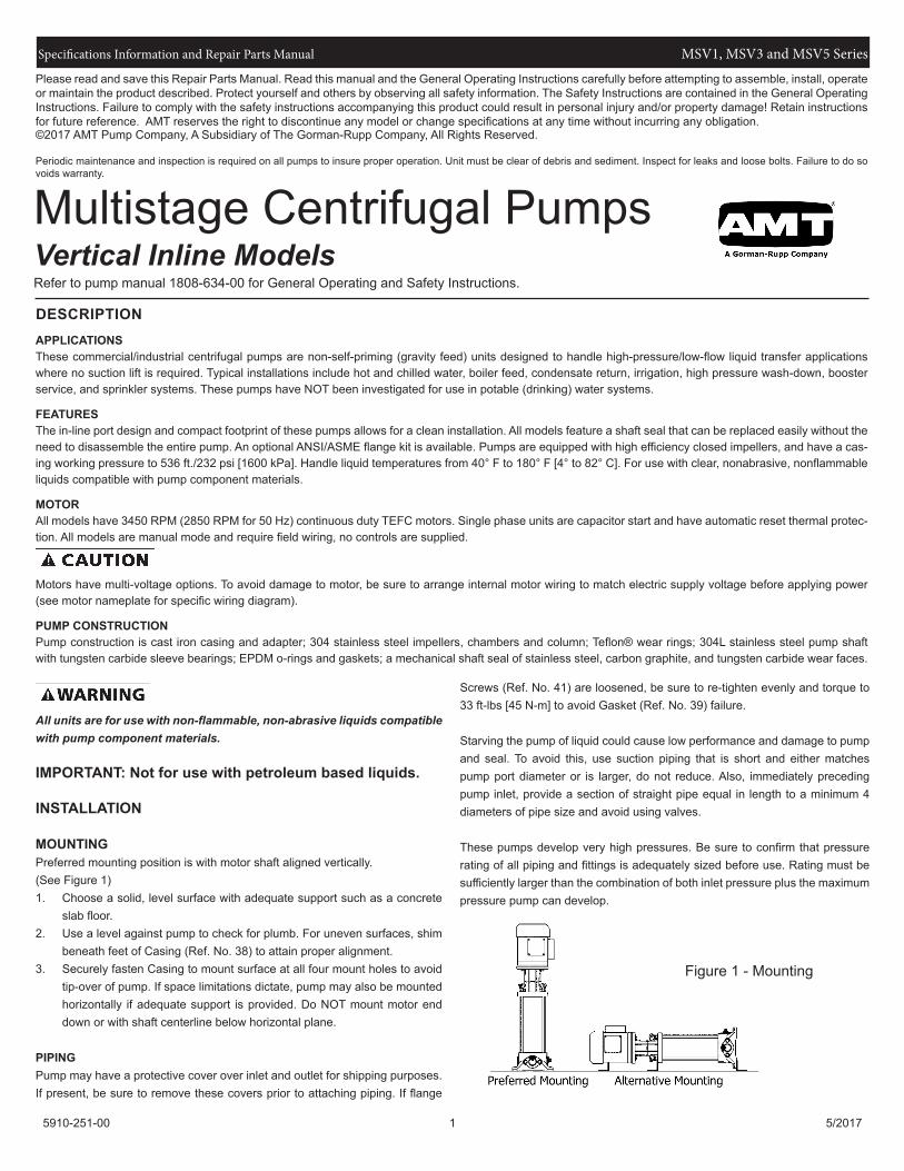
MOUNTINGPreferred mounting position is with motor shaft aligned vertically.(See Figure 1)1. Choose a solid, level surface with adequate support such as a concrete
slab floor.2. Use a level against pump to check for plumb. For uneven surfaces, shim
beneath feet of Casing (Ref. No. 38) to attain proper alignment.3. Securely fasten Casing to mount surface at all four mount holes to avoid
tip-over of pump. If space limitations dictate, pump may also be mounted horizontally if adequate support is provided. Do NOT mount motor end down or with shaft centerline below horizontal plane.
PIPINGPump may have a protective cover over inlet and outlet for shipping purposes. If present, be sure to remove these covers prior to attaching piping. If flange
Screws (Ref. No. 41) are loosened, be sure to re-tighten evenly and torque to 33 ft-lbs [45 N-m] to avoid Gasket (Ref. No. 39) failure.
Starving the pump of liquid could cause low performance and damage to pump and seal. To avoid this, use suction piping that is short and either matches pump port diameter or is larger, do not reduce. Also, immediately preceding pump inlet, provide a section of straight pipe equal in length to a minimum 4 diameters of pipe size and avoid using valves.
These pumps develop very high pressures. Be sure to confirm that pressure rating of all piping and fittings is adequately sized before use. Rating must be sufficiently larger than the combination of both inlet pressure plus the maximum pressure pump can develop.
DESCRIPTIONAPPLICATIONSThese commercial/industrial centrifugal pumps are non-self-priming (gravity feed) units designed to handle high-pressure/low-flow liquid transfer applications where no suction lift is required. Typical installations include hot and chilled water, boiler feed, condensate return, irrigation, high pressure wash-down, booster service, and sprinkler systems. These pumps have NOT been investigated for use in potable (drinking) water systems.
FEATURESThe in-line port design and compact footprint of these pumps allows for a clean installation. All models feature a shaft seal that can be replaced easily without the need to disassemble the entire pump. An optional ANSI/ASME flange kit is available. Pumps are equipped with high efficiency closed impellers, and have a cas-ing working pressure to 536 ft./232 psi [1600 kPa]. Handle liquid temperatures from 40° F to 180° F [4° to 82° C]. For use with clear, nonabrasive, nonflammable liquids compatible with pump component materials.
MOTORAll models have 3450 RPM (2850 RPM for 50 Hz) continuous duty TEFC motors. Single phase units are capacitor start and have automatic reset thermal protec-tion. All models are manual mode and require field wiring, no controls are supplied.
Motors have multi-voltage options. To avoid damage to motor, be sure to arrange internal motor wiring to match electric supply voltage before applying power (see motor nameplate for specific wiring diagram).
PUMP CONSTRUCTIONPump construction is cast iron casing and adapter; 304 stainless steel impellers, chambers and column; Teflon® wear rings; 304L stainless steel pump shaft with tungsten carbide sleeve bearings; EPDM o-rings and gaskets; a mechanical shaft seal of stainless steel, carbon graphite, and tungsten carbide wear faces.
Figure 1 - Mounting
Specifications Information and Repair Parts Manual MSV1, MSV3 and MSV5 Series
5910-251-00 2 5/2017
Piping and/or pipe fittings with an insufficient pressure rating may burst and cause personal injury and/or property damage.
MAXIMUM INLET PRESSURE“1” Series2 to 25 ...................................................................... 335 ft./145 psi [1000 kPa]27 stage ................................................................... 500 ft./217 psi [1500 kPa]
“3” Series2 to 15 ...................................................................... 335 ft./145 psi [1000 kPa]17 to 25 .................................................................... 500 ft./217 psi [1500 kPa]
“5” Series2 to 9 ........................................................................ 335 ft./145 psi [1000 kPa]10 to 29 .................................................................... 500 ft./217 psi [1500 kPa]
If system pressure has potential to exceed number listed above, then a check valve is required on discharge side of pump. This will ensure that proper inlet pressure is maintained when pump shuts off.
MAXIMUM OUTLET PRESSUREIf system pressure in excess of 536 ft./232 psi [1600 kPa] is possible, then it is necessary to provide means to prevent this. Examples include a bypass valve or pressure switch on discharge of pump set at or below this number.
OPERATION
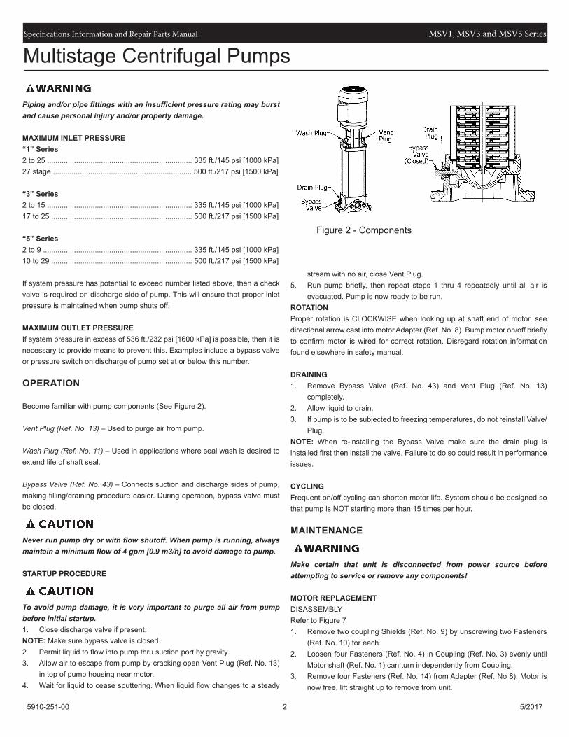
Become familiar with pump components (See Figure 2).
Vent Plug (Ref. No. 13) – Used to purge air from pump.
Wash Plug (Ref. No. 11) – Used in applications where seal wash is desired to extend life of shaft seal.
Bypass Valve (Ref. No. 43) – Connects suction and discharge sides of pump, making filling/draining procedure easier. During operation, bypass valve must be closed.
Never run pump dry or with flow shutoff. When pump is running, always maintain a minimum flow of 4 gpm [0.9 m3/h] to avoid damage to pump.
STARTUP PROCEDURE
To avoid pump damage, it is very important to purge all air from pump before initial startup.1. Close discharge valve if present.NOTE: Make sure bypass valve is closed.2. Permit liquid to flow into pump thru suction port by gravity.3. Allow air to escape from pump by cracking open Vent Plug (Ref. No. 13)
in top of pump housing near motor.4. Wait for liquid to cease sputtering. When liquid flow changes to a steady
stream with no air, close Vent Plug.5. Run pump briefly, then repeat steps 1 thru 4 repeatedly until all air is
evacuated. Pump is now ready to be run.ROTATIONProper rotation is CLOCKWISE when looking up at shaft end of motor, see directional arrow cast into motor Adapter (Ref. No. 8). Bump motor on/off briefly to confirm motor is wired for correct rotation. Disregard rotation information found elsewhere in safety manual.
completely.2. Allow liquid to drain.3. If pump is to be subjected to freezing temperatures, do not reinstall Valve/
Plug.NOTE: When re-installing the Bypass Valve make sure the drain plug is installed first then install the valve. Failure to do so could result in performance issues.
CYCLINGFrequent on/off cycling can shorten motor life. System should be designed so that pump is NOT starting more than 15 times per hour.
MAINTENANCE
Make certain that unit is disconnected from power source before attempting to service or remove any components!
MOTOR REPLACEMENTDISASSEMBLYRefer to Figure 71. Remove two coupling Shields (Ref. No. 9) by unscrewing two Fasteners
(Ref. No. 10) for each.2. Loosen four Fasteners (Ref. No. 4) in Coupling (Ref. No. 3) evenly until
Motor shaft (Ref. No. 1) can turn independently from Coupling.3. Remove four Fasteners (Ref. No. 14) from Adapter (Ref. No 8). Motor is
now free, lift straight up to remove from unit.
Figure 2 - Components
Multistage Centrifugal Pumps
Specifications Information and Repair Parts Manual MSV1, MSV3 and MSV5 Series
5910-251-00 3 5/2017
REASSEMBLY1. Remove key (if present) from new Motor shaft and discard.2. Wipe any protective film from Motor end bell and shaft, be sure they are
clean.3. Carefully guide Motor shaft into Coupling while setting new Motor into
place.4. Reinstall four Fasteners thru Adapter. Tighten evenly and in diagonal
pattern, then torque to the following specifications:3/8..................................................................................17 ft-lbs. [23 N-m]1/2..................................................................................30 ft-lbs. [41 N-m]
5. Locate shaft keyway in center of Coupling (See Figure 3) and maintain this position, then snug up Fasteners evenly. Check gap between coupling halves to be sure it remains even on both sides. Torque Fasteners to the following specifications.M6 .....................10 ft-lbs. [14 N-m]M8 .....................23 ft-lbs. [31 N-m] M10....................46 ft-lbs. [62 N-m]
6. Rotate pump Shaft by hand. If binding or rubbing is found, loosen Coupling and readjust position.
7. Reattach Shields and proceed to Startup Procedure section.
SHAFT SEAL REPLACEMENTDISASSEMBLYRefer to Figure 7.1. Remove Motor (see Motor Replacement section). 2. Remove Coupling (Ref. No. 3) and Rod (Ref. No. 2) by unthreading
Screws (Ref. No. 4).3. Loosen, but do not remove set screws in Shaft Seal Assembly (Ref. No.
7).4. Unscrew Shaft Seal Assembly in a counter-clockwise direction, then
carefully lift off of Shaft (Ref. No. 21).
REASSEMBLY
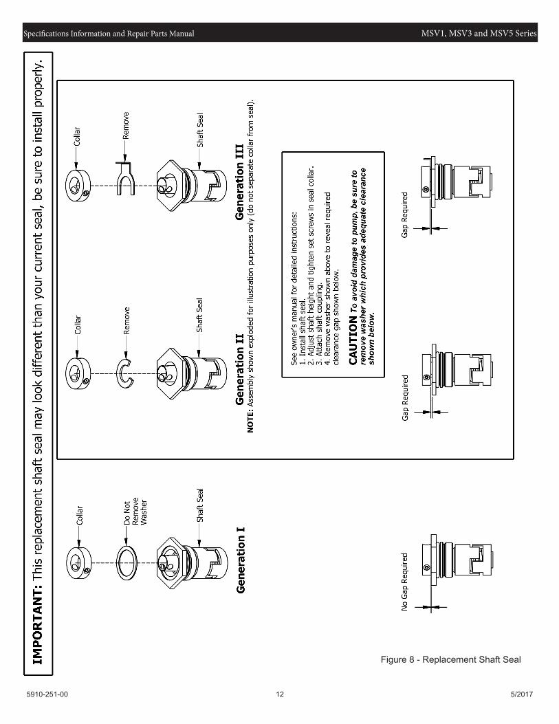
IMPORTANT: Pump Shaft may have been gouged from set screws. Before installing new Shaft Seal Assembly, smooth-over these gouges with a light grit emery cloth to prevent damage to new seal.1. Once shaft is free of burrs, lubricate Shaft and o-ring cavity in Adapter
(Ref. No. 8) with soapy water.2. Carefully slide new Shaft Seal Assembly onto Shaft, then tighten in
clockwise direction and torque to 26 ft-lbs [35 N-m].3. Mark or otherwise note shaft height. Lift shaft as high as it will go, then
lower it back down ½ the total distance. Maintain this position while evenly tightening 3 set screws in seal collar and torque each to 2 ft-lbs. [2.5 N-m].
4. Place Rod thru Shaft, then reinstall Coupling and screws but do NOT tighten.
5. Proceed to Reassembly under Motor Replacement section.
PUMP OVERHAUL/INSPECTION
To inspect condition of pump internals, proceed as follows:
NOTE: To facilitate overhaul, a handy holding device can be made easily. Take a short piece of 2×4 lumber and on the narrow side, drill a 1/2” diameter blind hole 3” deep. Place block into bench vice with hole facing up to receive pump shaft after step 5 (see Figure 4).
DISASSEMBLY1. Proceed to Disassembly under Shaft Seal Replacement.2. Remove 4 Fastener sets (Ref. Nos. 15 & 16).3. Lift Adapter (Ref. No. 8) from pump, use a soft mallet to break loose
if necessary. NOTE: Inspect o-ring groove in Adapter after o-ring is removed. Rust/pitting in this region may cause leaks, be sure to clean or replace Adapter entirely if damage is excessive.
4. Remove wave Spring (Ref. No. 18) from Adapter. NOTE: Inspect wave Spring for cracks and replace if found.
5. Pump internals can now be removed all at once. Use pump Shaft (Ref. No. 21) as a handle and gently lift the entire assembly out. If stage-1 Volute (Ref. No. 38) stays behind, it can be removed and inspected later.
Figure 3 - Coupling Alignment
Figure 4 - Inspection
Multistage Centrifugal Pumps
Specifications Information and Repair Parts Manual MSV1, MSV3 and MSV5 Series
5910-251-00 4 5/2017
IMPORTANT: Stainless steel components deform easily, be careful to avoid damaging pump components during disassembly.6. Unscrew Hex Nut (Ref. No. 37) from pump Shaft in a counter-clockwise
direction and remove along with Sleeve Cup (Ref. No. 35).7. Lift Volute (if still present) and Impeller (Ref. No. 26) from stack and set
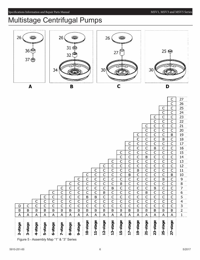
aside.IMPORTANT: Take note of sequence parts are arranged in and direction they are facing, number and mark if necessary (see Figure 6 & 7).8. Lift next Volute/Crossover (Ref. No. 34), Inner Bearing (Ref. No. 32), and
Impeller from stack.NOTE: Inspect Inner and Outer Bearings for wear. If grooves can be seen or felt, replace both bearings as a set.9. Use a large straight blade screwdriver to carefully pry Cap (Ref. No. 28)
from Crossover to free Wear Ring (Ref. No. 29).NOTE: Inspect for wear by placing Wear Ring over nose of Impeller and noting clearance between two diameters. If fit is not snug, replace Wear Ring.10. Repeat Steps 7 and& 8 for each stage (some stages have no bearings)NOTE: Inspect Shaft (Ref. No. 21) for grooves, replace if splines are worn. 11. Lift Cylinder (Ref. No. 20) from Casing (Ref. No. 39), use a soft mallet to
break loose if necessary.NOTE: Inspect o-ring groove in Casing after o-ring is removed. Rust/pitting in this region may cause leaks, be sure to clean or replace Casing entirely if damage is excessive.12. If stage-1 Volute (Ref. No. 38) remains in Casing, now is the time to
remove it. Gently pry loose with a straight blade screwdriver, being careful to avoid bending it.
13. Unscrew 2 fasteners (Ref. No. 42).14. Use a straight blade screwdriver to pry pipe Flange (Ref. No. 41) loose.15. Use a putty knife to scrape off old Gasket (Ref. No. 40) from Flange and
Casing.
REASSEMBLY1. Always use new Gaskets (Ref. No. 40) when reassembling. Attach pipe
Flanges (Ref. No. 41) with Fasteners (Ref. No. 42). Tighten evenly and torque to 33 ft-lbs [45 N-m].
2. Place new O-ring (Ref. No. 19) into cleaned groove of Casing (Ref. No. 39), be sure to lubricate with soapy water or suitable material.
3. Place stage-1 Volute (Ref. No. 38) back into Casing (Ref. No. 39) making sure it is seated properly.
4. Carefully guide Cylinder (Ref. No. 20) back into Casing and press down.IMPORTANT: If Cylinder does not fully seat, O-ring may be pinched. If this occurs, lift Cylinder back out and try stretching O-ring. Be sure components are adequately lubricated and have not been damaged. Repeat process until end of Cylinder bottoms on Casing.5. Reassemble Impellers (Ref. No 26), Crossovers (Ref. No. 34), etc. onto
pump Shaft (Ref. No. 21) in same order they were removed (see Figure 6 & 7) and torque Hex Nut w/Nyloc (Ref. No. 37) to 13 ft-lbs [18 N-m]
IMPORTANT: NEVER reuse Hex Nut w/Nyloc, ALWAYS replace with new unused one.6. Take Impeller/Crossover stack by Shaft and lower into pump until properly
seated.7. Place new O-ring (Ref. No. 19) into cleaned groove of Adapter (Ref. No.
8), be sure to lubricate with soapy water or suitable material.
8. Install wave Spring (Ref. No. 18) with ends pointed towards Adapter. With wave Spring seated on proper landing in Adapter, carefully guide Adapter onto pump and press down.
IMPORTANT: If Adapter does not fully seat, O-ring may be pinched. If this occurs, lift Cylinder back out and try stretching O-ring. Be sure components are adequately lubricated and have not been damaged. Repeat process until Adapter bottoms on end of Cylinder.9. Reinstall Fasteners (Ref. Nos. 15 & 16) onto Staybolts (Ref. No. 17) and
tighten diagonally.10. Proceed to Reassembly portion of Shaft Seal Replacement.
Multistage Centrifugal Pumps
Specifications Information and Repair Parts Manual MSV1, MSV3 and MSV5 Series
5910-251-00 5 5/2017
Problem Possible Cause(s) Corrective ActionThe pump does not run 1. No power at motor. 1. Check for voltage at motor terminal box. If
no voltage at motor; check feeder panel for tripped circuits and reset.
2. The Fuses are blown. 2. Replace fuses. 3. Motor starer overloads are burned or
have tripped out.3. Check for voltage on line and load side for
starter. Consult certified electrician. 4. The motor is defective 4. Replace motor.The pump runs but at reduced capacity, low discharge pressure or does not deliver
1. Wrong Rotation 1. Check wiring for proper connections.
2. Pump is air locked 2. Turn pump off, purge the air from the pump via the vent plug. NOTE: May take multiple attempts to vent all air from the pump.
Make sure the bypass valve is closed and installed correctly.
3. The pump inlet pressure is too low. 3. Check inlet conditions. 4. The pump draws air. 4. Check inlet conditions.
Turn pump off, purge the air from the pump via the vent plug. NOTE: May take multiple attempts to vent all air from the pump.Make sure the bypass valve is closed and installed correctly.
5. Strainers, check valves or foot valves are clogged
5. Remove strainer, screen or valve and inspect. Clean and replace.
6. Incorrect drain plug installed. 6. If the proper drain plug that was supplied with the pump originally was replaced with standard plug, water will recirculate inter-nally. Replace with Proper plug.
7. High friction loss in line 7. Remove kinks and elbows, reduce length 8. Discharge head too high 8. Lower end of discharge line. 9. Clogged impeller 9. Remove clog 10. Worn/damaged impeller 10. Replace parts as requiredLeakage in shaft seal 1. The shaft seal is defective 1. Replace the shaft seal.Noise 1. Cavitation 1. Check the inlet conditions. 2. The pump does not rotate freely. 2. Check for frictional resistance as a result
of incorrect pump shaft position. Adjust the pump shaft per manual instructions.
3. Strainers, check valves or foot valves are clogged
3. Remove strainer, screen or valve and inspect. Clean and replace.
Multistage Centrifugal Pumps
Specifications Information and Repair Parts Manual MSV1, MSV3 and MSV5 Series
5910-251-00 6 5/2017
Multistage Centrifugal Pumps
Figure 5 - Assembly Map “1” & “3” Series
Specifications Information and Repair Parts Manual MSV1, MSV3 and MSV5 Series
5910-251-00 7 5/2017
Multistage Centrifugal Pumps
Figure 6 - Assembly Map “5” Series
Specifications Information and Repair Parts Manual MSV1, MSV3 and MSV5 Series
5910-251-00 8 5/2017
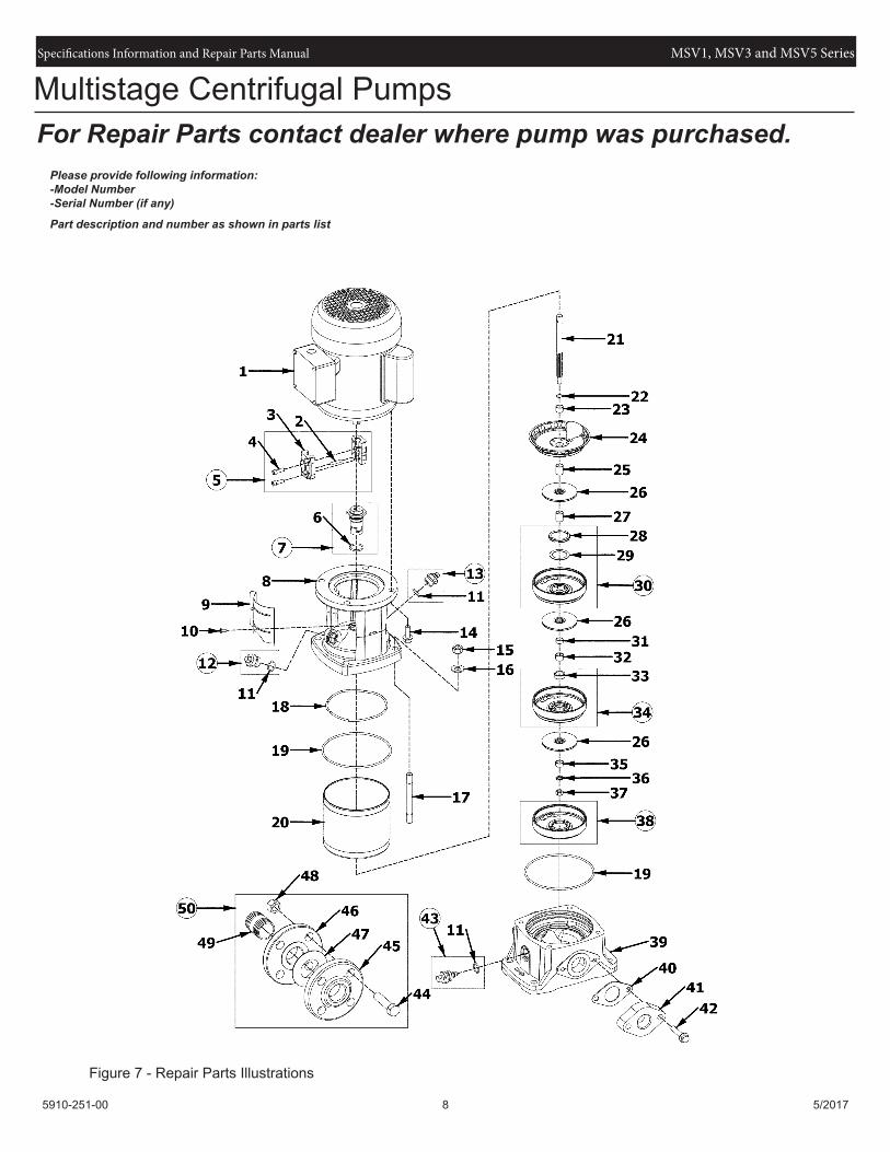
For Repair Parts contact dealer where pump was purchased.Please provide following information:-Model Number-Serial Number (if any)
Part description and number as shown in parts list
Figure 7 - Repair Parts Illustrations
Multistage Centrifugal Pumps
Specifications Information and Repair Parts Manual MSV1, MSV3 and MSV5 Series
5910-251-00 9 5/2017
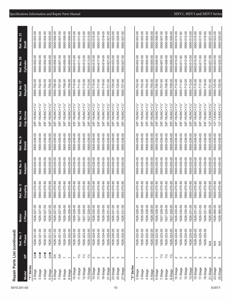
Repair Parts ListRef. Part Number for Models:No. Description “1” Series “3” Series “5” Series Qty.1 Motor See Page 9 See Page 9 See Page 10 12 Rod 5900-072-00 5900-072-00 5900-072-00 13 Coupling Incl. w/Ref 5 Incl. w/Ref 5 Incl. w/Ref 5 24 Socket Head Cap Screw - ISO Class 12.9 * Incl. w/Ref 5 * Incl. w/Ref 5 * Incl. w/Ref 5 45 Coupling Kit (ncludes Ref. Nos. 2, 3, 4) See Page 9 See Page 9 See Page 10 16 O-ring - EPDM * M2.65×22.4 * M2.65×22.4 * M2.65×22.4 17 Shaft Seal - EPDM, Carbon, Tungsten Carbide (Includes Ref. No. 6) 5900-300-00 5900-300-00 5900-300-00 18 Adapter See Page 9 See Page 9 See Page 10 19 Shield See Page 9 See Page 9 See Page 10 2
10 Pan Head Machine Screw * M4-0.7×8 * M4-0.7×8 * M4-0.7×8 411 O-ring - EPDM * M2.4×17.8 * M2.4×17.8 * M2.4×17.8 312 Wash Plug Assembly (Includes Ref. No. 11) 5900-044-90 5900-044-90 5900-044-90 113 Vent Plug Assembly (Includes Ref. No. 11) 5900-044-90 5900-044-90 5900-044-90 114 Hex Head Cap Screw - SAE Grade 5 * See Page 9 See Page 9 See Page 10 415 Hex Nut - ASTM Class A2-70 * M12-1.75 * M12-1.75 * M12-1.75 416 Flat Washer - SS * M12 * M12 * M12 417 Staybolt (multiple lengths) See Page 9 See Page 9 See Page 10 418 Spring 5900-036-00 5900-036-00 5900-036-00 119 O-ring - EPDM * M3.5×138 * M3.5×138 * M3.5×138 220 Cylinder (multiple lengths) See Page 9 See Page 9 See Page 10 121 Shaft (multiple lengths) See Page 9 See Page 9 See Page 10 122 Retaining Ring 5900-090-00 5900-090-00 5900-090-00 123 Collar 5900-086-00 5900-086-00 5900-086-00 124 Top Plate Weldment w/Crossover (Standard) 5900-172-00 5900-172-00 5930-172-00 1