DRIVE DIRECTIVE FOR TUNNEL EXECUTION IN MANIPUR REGION (NORTH-EAST ) INDIA By Mr. Pradeep Goswami Chief Geologist, Coastal Projects Ltd. Manipur Presented in Jiribam-Tupul(Manipur) New BG Line, North-East Frontier Railway P. Goswami
Transcript
DRIVE DIRECTIVE FOR TUNNEL
EXECUTION IN MANIPUR REGION
(NORTH-EAST ) INDIA
By
Mr. Pradeep Goswami Chief Geologist, Coastal Projects Ltd. Manipur
Presented in Jiribam-Tupul(Manipur) New BG Line,
North-East Frontier Railway
P. Goswami
Introduction The NATM method has been developed basically in
Austria so its name make use of providing flexible primary lining in shape of shotcrete, wire mesh, rock bolts ,lattice girder. In case of weaker rock mass the use of pipe forepole/pipe roofing is also restricted for crown support which in turn lead to less over break as well as ensure safety during the execution. The main aspect of the approach is dynamic design based on rock mass classification as well as the in situ deformation observed. Hence more economical use of the tunnel support system along with the rational approach of execution.
P. Goswami
The name New Austrian Tunneling method (NATM) is a misnomer as it is not a method of tunneling but a strategy for tunneling which does has a considerable uniformity and sequence. The NATM is based on philosophy of ‘Building as you go’ approach with the following caution. “Not too stiff, nor too flexible Not too early, nor too late”. The NATM accomplishes tunnel stabilization by controlled stress release. The surrounding rock is thereby transformed from a complex load system to a self-supporting structure together with the installed support elements, provided that the detrimental loosening, resulting in a substantial loss of strength, is avoided.
P. Goswami
Cont… The self stabilization by controlled stress release is
achieved by the introduction of the so called “semi-Rigid Lining” i.e. systematic rock bolting with the application of shotcrete lining. On one side, this offers a certain degree of immediate support, and the flexibility to allow stress release through radical deformation on the other hand. The development of shear stress in shotcrete lining in ached roof is thus reduced to minimum.
P. Goswami
History of NATM The term New Austrian Tunneling Method
Popularly Known as NATM got its name from Salzburg (Austria). It was first used by Mr. Rabcewicz in 1962. It got world wise recognition in1964. This method has been evolved as a result of experience gained in Austrian Alpine tunneling condition. The first use of NATM in soft ground tunneling is done in Frankfurt metro in 1969. The basic aim of NATM is for getting stable and economic tunnel support systems. This method has been very useful in complex diversified geological condition where forecasting of the rock mass is difficult due to rapidly changing geology.
P. Goswami
The Basic principles of NATM I. Mobilization rock mass strength
II. Shotcrete protection to preserve the load-carrying capacity of the rock mass,
III. Monitoring the deformation of the excavated rock mass.
IV. Providing flexibility but active supports, and
V. Closing of invert to form a load-bearing support ring to control deformation of the rock mass.
P. Goswami
Rock support system based on Rock Classification
NATM Support Elements Fore Poling Drilling Loading Blasting Mucking Scaling/Chipping Face Sealing Wire Mesh Steel Rib/Lattice Shotcrete Systematic Rock Bolting
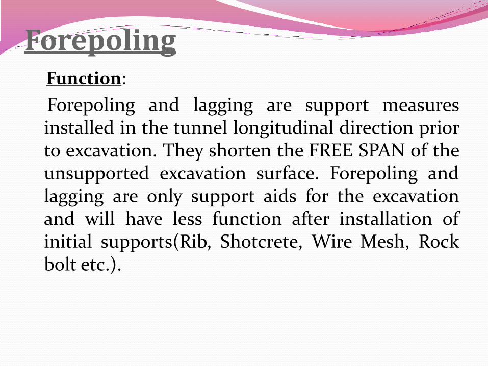
Forepoling Function:
Forepoling and lagging are support measures installed in the tunnel longitudinal direction prior to excavation. They shorten the FREE SPAN of the unsupported excavation surface. Forepoling and lagging are only support aids for the excavation and will have less function after installation of initial supports(Rib, Shotcrete, Wire Mesh, Rock bolt etc.).
Forepoling Driving Method
Start drilling out of the center with two booms. Prepare Grouting Equipment now. As soon as the gap between the booms is as big that the bucket will fit in, go up with the loaded forepole bars at the basket and start installing them, after you have filled up the Drilled-holes with the grout. As soon as one boom is finished with drilling for Forepoling it will switch over immediately to drill blasting holes. The second boom will push forpoling bars into the deepest depth as possible into the hole, if necessary, than it will switch over also to drilling for blasting. Amount and depth of the needed holes find in present site instruction and follow instructions strictly.
Fixing of Forepoling
P. Goswami
Types of Forepoling Pipes (Diameter 1¼ - 1¾ inch)
Rods ( Diameter around 32mm)
Self drilling bolts
Channel Forepoling
P. Goswami
Three different methods of forepoling can be mentioned- 1. Sub- horizontal jet grouting method
2. Spiling method
3. Pipe roof method
Forepoling is generally employed under the following conditions :
- The existence of shallow overburden above the
tunnel
- The need to restrict ground surface settlement
- Poor ground conditions
P. Goswami
The Jet grouting method Jet grouting is used in especially difficult conditions
where both weak soils and thin over burden occur. Jet grouting is normally used in sandy or gravel formations. It should be noted that jet grouted, reinforced column and a drilled or driven pipe ( pipe roof method) work as a beam, while treated soil in the spiling method makes the structure function as an arch.
P. Goswami
The Spiling Method The Spiling method consists of four different parts: - Drilled steel pipe - Grout inside the pipes and in voids outside - Treated ground by permeation or fracture grouting - Steel arch supports
P. Goswami
Drilling for Blasting Both booms start drilling profile out of the top centre,
one left, and one right down to knee hole. After finished Profile Line start again on the Top centre drilling from inside to out side horizontal for open up ASAP gap for basket. Then finish middle and lower part including Cut. Meanwhile drilling Lower Point, the bottom area needs to be cleaned out by hand. After that drill bottom-line. Make sure that all holes are cleaned nicely to have easy charging after. Depths of drilling holes find into present site instruction and follow instruction strictly.
P. Goswami
Drilling in Progress
P. Goswami
Charging Start charging face at least 15 minutes after start
drilling out a safe position. Charging should be done always from the top to bottom (above booms, about safety reasons) charging upto 2m heights should be done always in safety distance to drilling boom. Take blasting cord with in the basket and correct detonator straight after hole is finished charged. As soon as charging out of the basket is done prepare ignition-cable and correct electrical dets. Wheel-loader and Dumper trucks have to be organized before blasting and placed inside Tunnel.
P. Goswami
Explosive Loading in Progress
P. Goswami
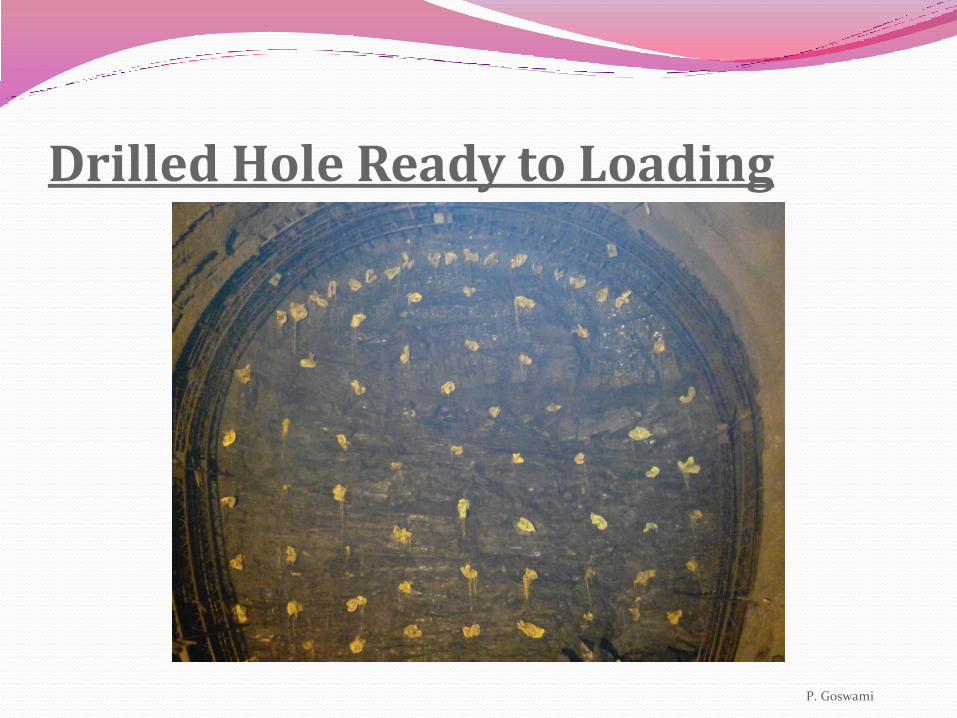
Drilled Hole Ready to Loading
P. Goswami
Mucking Important during mucking is to have enough Dump Truck
running, so that there is no delay in between mucking itself while waiting for Trucks. Truck has to be as close as possible to Muck Pile(Max.10m) waiting trucks have to be placed close to loading bay to guaranty that the replacing of unloaded and loaded truck is possible meanwhile the wheel-loader is loading itself at Muck Pile. Mucking has to be not lower than the bottom plate of last lattice girder. Latest after 50% of mucking time it needs to organize the shotcrete robot and the shotcrete itself, so that the robot is connect and transits miller is standing behind robot close to the face when the excavator, after scaling, is leaving the face.
P. Goswami
Mucking in Progress
P. Goswami
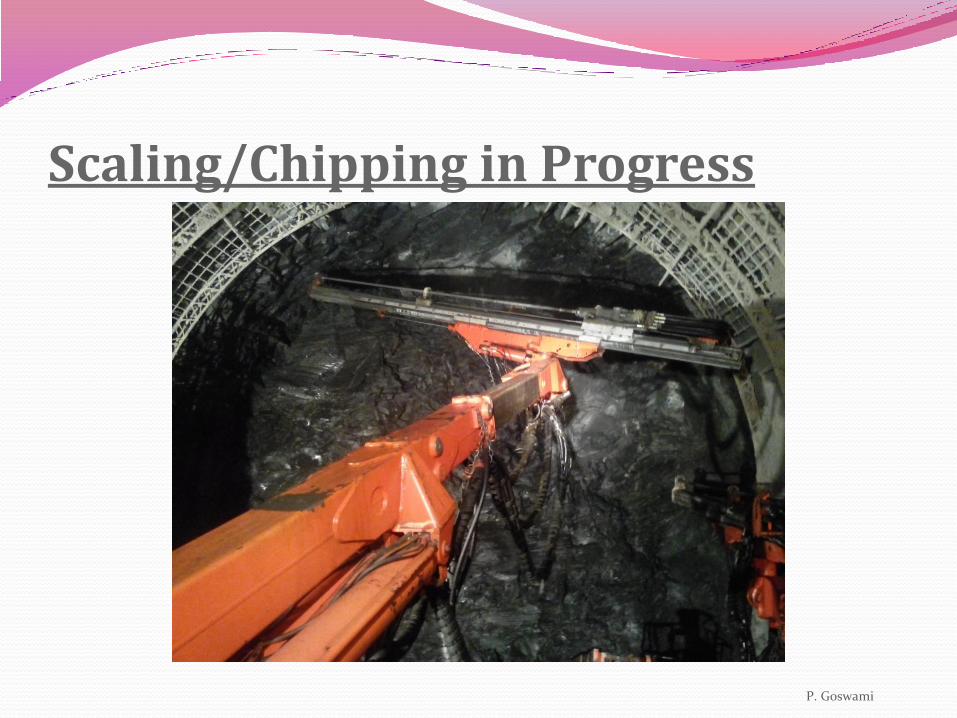
Scaling/Chipping The Excavator is standing more or less close to the
face. As soon as the wheel-loader is moving out, it’s going in and start scaling loose rocks down from the face and preparing the rough profile so that there is no “under-profile”. Then preparing also a rough stand for the robot and if necessary a small drainage etc.
P. Goswami
Scaling/Chipping in Progress
P. Goswami
Pre Shotcrete/Face sealing First the profile and the after needs to be washed down so
that there will be a good connection between rock and shotcrete. Areas where are over break situations should be sparyed first with a thin layer(max 10 cm). The shotcrete needs to be sprayed from the bottom upwards to have a good abutment for upper shotcrete. After a while it needs to go back to “over Break” area for the next thin layer. Two third of the face needs to be sprayed I between as face support. Pre shotcrete has to finish at least 80% of the total needed shotcrete, preparing the rough profile as much as possible, so that after wire mesh and lattice girder the second shotcrete is more or less only the final polishing. Maximum thickness of shotcrete read out of present site instruction.
P. Goswami
Face recently opened sealed with Shotcrete
P. Goswami
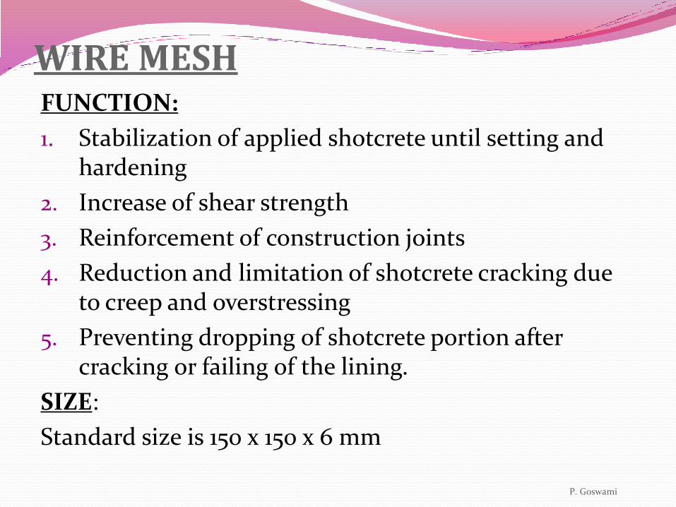
WIRE MESH FUNCTION:
1. Stabilization of applied shotcrete until setting and hardening
2. Increase of shear strength
3. Reinforcement of construction joints
4. Reduction and limitation of shotcrete cracking due to creep and overstressing
5. Preventing dropping of shotcrete portion after cracking or failing of the lining.
SIZE:
Standard size is 150 x 150 x 6 mm
P. Goswami
Wire mesh placing method Place wire mesh at the bottom of left hand profile and
connect with overlapping from last wire mesh. Lift up Jumbo Basket and bring it into the finally position. Press it close to the rock and tie it with 2 mm wire at the overlapping. Do the same with the right hand profile. Last wire mesh needs to be installed on top with overlapping of three squares to left and right hand wire mesh. Don’t wire up the three units in between, just at the overlapping area!! Wire mesh needs to be movable during the installing of the lattice girder.
P. Goswami
Wire Mesh
P. Goswami
Wire Mesh Fixing
P. Goswami
Method of Placing Lattice Girder Lift up the LG by basket and chain around two meter
and drop it against the face. Release chain install “T-Piece” at basket and lift up LG exactly to centerline check correct heights by supervisor. Install immediately spacers in Top-shoulder and bottom area hold these position by basket and right-hand shoulder area should hold in present position by right-hand boom. Now bring the left-hand shoulder with left-hand boom into the position given by the supervisor. Measure from the marked centerline at face the needed space between centerline and left-hand bottom plate of L.G.(3.03m).
P. Goswami
Bring bottom plate to exact position and secure it with stones, timber etc. elevation is not relevant at this moment. Still hold the position by basket and now left-hand shoulder area should hold correct position by left-hand boom. Now bring the right-hand shoulder with right-hand boom into the position given by surveyor.
Measure from the marked centerline at face the needed space between centerline and right-hand bottom plate of L.G.(3.03m). Bring bottom plate to exact position and secure it with stones, timber etc. elevation is not relevant at this moment. Connect the wiremesh at LG, tie the spacers to the wiremesh .
P. Goswami
Lattice Girder
P. Goswami
Functions of Lattice Girder 1. Steel Rib/Lattice Girder Composite structure of
lattice girder and concrete confined to load distribution.
2. Carrying of “Green” shotcrete.
3. Profile control
4. Support for forepoling
P. Goswami
SECOND SHOTCRETE Start spraying at the bottom area of previous lattice
girder move in direction to new lattice girder to secure the girder at bottom area first. Spray around 1m high, than switch over to other side of Lattice Girder and do the same over there. Without doing these, the possible overloading with shotcrete at one side,will push the whole Lattice Girder out of direction. Now spray the area of the old LG and old overlapping first to secure the new Wiremesh. After that do the same with the area at new LG.ter the LG is covered nicely with shotcrete spray the profile from one side bottom to another side bottom, so that the wiremesh is covered with shotcrete max. 3 m inside. Make sure that the thickness of shotcrete is as written in present site instruction. P. Goswami
FUNCTIONS OF SECOND SHOTCRETE
1. As sealing Shotcrete:
Avoids first loosening of the surrounding ground.
Closes joints and prevents fall-downs; so activating the rock arch.
Seals the surrounding ground (air sensitive grounds).
2. As main shotcrete (carrying member)
To carry the load introduced by the ground in the lining (mainly normal forces, no bending moments if tunnel shape optimal).
P. Goswami
Shotcreteing in Progress
Rock Bolting Mark the position of rockbolts with spraypoint. Start
drilling from the top down, so that the basket is able to work above the boom, as soon as the first hole is drilled. Depend on what kind of rockbolt needs to be installed carry on like explained below -
Types of Rock Bolts SN-Bolt: Fill up the holes with a stiff grout. Install the rockbolt by hand or by
boom. Install the plate and screw the nut on by hand. SDR-Bolts: Install the Rockbolt at the Boom and drill it in the full length, after
that pull back 5 cm to make sure that the grout is able to squeeze out of the drill bit. Disconnect SDR FROM hammer and do the next SDR the same way. Now you have to close the gap around the installed SDR (empty cement bag etc.) so that no Grout is flowing out. Than Grouting Crew is connecting Grout hose to SDR and is pumping in the Grout into the SDR until Grout is flowing out through the “cement bag”. Then place and tie the Nut by spanner. Now pump again until the Grout will squeeze out between Rock and Plate.
SYSTEMATIC ROCK BOLTING ANCHOR MORTAR:
1. Rock bolts must be fully grouted(except expansion bolts)
2. Behavior of the anchor mortar is of significance:
Its ultimate strength must not be reduced to any great extent as result of displacements, affecting the mortar during the setting time.
The quality of the mortar influence considerably the success of the anchoring system.
MORTAR TYPES:
Special anchor mortar with expanding agent
Cement – sand mixture(1:2)
Net Cement (for injection bolts)
DIRECTION OF ROCK BOLTS
In general the direction of rock bolts shall be radial, i.e.
perpendicular to the lining (±10 degrees). It may deviate from the general radial direction to cope with unfavorable bedding, etc.
P. Goswami
Systematic Rock Bolting In Progress with Rocket Boomer
Drive Direction for 1.00M Pull Sr. No. Item Works Duration Remarks
1 Fore Poling 1 Hour
2 Drilling For Blasting
1 Hour
3 Charging, Blasting & Defuming
1 Hour and 40 Minutes
Wheel-loader & Dump Trucks have to be organized before blasting & placed inside Tunnel.
4 Mucking 3 Hour Latest after 50% of Mucking Time it needs to organize the shotcrtete Robot and the shotcrete itself, so that the robot is connect and the Mix Truck is standing behind Robot close to the Face when the Excavator, after scaling , is leaving the face.
5 Scaling 20 Minutes
6 Pre Shotcrete/Face
Scaling
1 Hour As soon as the Pre shotcrete is running wire mesh and Lattice Girder has to be prepared and placed close to the face, needed equipment (Jumbo) has to be arranged as close as possible to Plugbox.
7 Wire Mesh 30 Minutes Don’t wire up the three unites in between, just at the overlapping area! Wire mesh needs to be movable during the installing of the lattice girder.
8 Lattice Girder 1 Hour Meanwhile the lattice girder will set up into right position make sure that the robot is waiting close to the switchbox & Mixtruck with shotcrete is inside tunnel.
9 Second Shotcrete 30 Minutes During spraying the second layer of shotcrete prepare Rockbolts, Plates etc. and place everything close to Face. Make sure that the Equipment like Grout pump and Jumbo is as close as possible to the switchbox, ready to be connected.
10 Rock Bolting 45 Minutes
Total Duration 10 Hr. 45 Min.
TIME CYCLE PATHS
Start at Point one the Next cycle!! These directives has to be seen more as Guide Line than as
Directive. It shows the standard Cycle in standard conditions. Depends on different rock conditions and other circumstances it may change into other priorities of doing the cycle. In the summary of experience it will help to set up a system in doing tunnel the NEW AUSTRIAN TUNNELING METHOD.