21
NIST/NSLS-II BEAMLINES 7-ID-1 & 7-ID-2 (SST) COMMISSIONING PLAN February 7, 2018 NSLSII-7ID-PLN-001 REV 1
NIST/NSLS-II BEAMLINES 7-ID-1 & 7-ID-2 (SST) COMMISSIONING PLAN
February 7, 2018
NSLSII-7ID-PLN-001
REV 1
ii National Synchrotron Light Source II
ii
NIST/NSLS-II BEAMLINES7-ID-1& 7-ID-2 (SST) COMMISSIONING PLAN
February 7, 2018
PREPARED BY:
1/31/2018
X Cherno JayeCherno JayeSST-1 Lead Beamline ScientistSigned by: Jaye, Cherno
1/30/2018
X Conan WeilandConan WeilandSST-2 Lead Beamline ScientistSigned by: Weiland, Conan
APPROVED BY:
2/7/2018
X paul zschackPaul ZschackPhoton Science Division DirectorSigned by: Zschack, Paul

iii National Synchrotron Light Source II
iii
REVISION HISTORY
REVISION DESCRIPTION DATE
1 First Issue 07FEB2018
Acronyms
CSS Control System Studio
DCM Double Crystal Monochromator
DM Diagnostic Module
DS Downstream
EEI Electrical Equipment Inspection
EPS Equipment Protection System
ESH Environment, Safety and Health
ESR Experiment Safety Review
FE Front End
FOE First Optical Enclosure
FLUKA FluktuierendeKaskade (Monte Carlo simulation software)
FM Fixed Mask
FS Fluorescent Screen
ID Insertion Device
IRR Instrument Readiness Review
Ln nth Mirror on Tender Branch
Mn nth Mirror on Soft Branch
NSLS-II National Synchrotron Light Source II
PASS Proposal, Allocation, Safety, and Scheduling
PBS Pink Beam Stop
PDS Photon Delivery System
PGM Plane Grating Monochromator
PPS Personnel Protection System
PSH Photon Shutter
PSD Photon Science Division
RC Radiation Control
SAF Safety Approval Form
SR Synchrotron Radiation
SST Spectroscopy Soft and Tender
US Upstream
WBS White Beam Stop
iv National Synchrotron Light Source II
iv
Table of Contents
1. OVERVIEW..................................................................................................................................................................................1
2. SHIELDING..................................................................................................................................................................................2
3. APPROVAL OF COMMISSIONING ACTIVITY.....................................................................................................................2
4 ADDITION OF EQUIPMENT TO EXPERIMENTAL STATIONS........................................................................................3
5. SST BEAMLINE COMMISSIONING.....................................................................................................................................3
5.1 Phase I – Technical Commissioning.......................................................................................................................3
5.1.1 SST Beamline Commissioning Without Beam......................................................................................................6
5.1.2 SST Beamline Commissioning With Beam............................................................................................................8
5.2 Phase II – Scientific Commissioning.....................................................................................................................13
6 END OF COMMISSIONING: TRANSITION TO OPERATIONS......................................................................................14
7 REFERENCES...........................................................................................................................................................................14
Appendix: SST Beamline Layout Diagram..........................................................................................................................16

1 National Synchrotron Light Source II
1
BEAMLINE COMMISSIONING TEAM
Cherno Jaye (SST-1 Lead Beamline Scientist)
Conan Weiland (SST-2 Lead Beamline Scientist)
Daniel Fischer (SST Authorized Beamline Staff)
Joseph Woicik (SST Authorized Beamline Staff)
Nick Quackenbush (SST Authorized Beamline Staff)
Eliot Gann (SST Authorized Beamline Staff)
1. OVERVIEW
The NSLSII SST (Spectroscopy Soft and Tender) 07-ID Beamline complex consists of an inboard Tender
branch, an outboard Soft branch and a Transfer branch from the Soft to the Tender experimental stations. The purpose of this plan is to outline the actions needed to commission the NSLS-II SST (07-ID) Beamline from the first optical enclosure (FOE) to the NEXAFS (Soft branch) and HAXPES (Tender branch) experimental stations. Once the readiness process is complete and authorization to begin commissioning the beamline is received, the technical commissioning will proceed. The commissioning of the SST Beamline will be carried out in two separate phases. The first phase, the technical phase, will be carried out initially in close collaboration with the RC and ESH staff until it is deemed safe to operate in normal operations and will involve delivery of the beam to the FOE and beamline components for the purpose of radiation survey; alignment and conditioning of FOE and beamline components (vacuum and optics), calibration of beamline optics and testing of electronic components at low ring current. This will also include the comprehensive radiation survey to be performed at
a ring current of 125 mA with the photon beam in the monochromators. The latter stage of this phase will involve delivery of the beam to the beamline optics, HAXPES and NEXAFS experimental stations for the purpose of calibration, characterization and optimization in preparation of normal operations.
The second phase, the science phase, will focus on commissioning, in sequence, all the capabilities of the SST complex. This [latter] phase will also include guest-assisted commissioning of science experiments. The science commissioning plan will be provided separately.

2 National Synchrotron Light Source II
2
The scope of this plan includes managing specific technical commissioning activities for the SST beamline.
2. SHIELDING
Ray tracing (PD-SST-RAYT-0001) and computer simulation reports indicate that 07-ID is sufficiently shielded for the maximum planned stored electron beam current of 500 mA. All the ray traces have been completed in accordance with Synchrotron and Bremsstrahlung Ray Trace Procedure (PS-C-XFD-PRC-008) and Insertion Device Front End Ray Tracing Procedure (PS-C-ASD-PRC-147) and top-off safety analyzed (NSLSII-TOS-RPT-016). There is one Pb primary Bremsstrahlung shielding and a W primary Bremsstrahlung stop within the 7-ID FOE. The FOE also has two secondary Bremsstrahlung shields designed according to NSLS-II guidelines. The secondary [gas] Bremsstrahlung analysis was performed using FLUKA calculations, and it showed that the secondary shields are adequate at 500 mA ring current with an additional 5 cm Pb secondary Bremsstrahlung shield located just downstream of the FOE Downstream Panel. The first 5 and 3 m sections of the Tender and Soft pink beam transport pipes, respectively, DS of the FOE are also shielded with 8 mm lead. However, a small section of the beampipe just US of the PGM [on the Soft branch] is shielded with extra SS as shown by Synchrotron scattering analysis using STAC8. All bellows from the FOE to the precision slits and the bellows immediate DS and US of the DCM [on the Tender branch] are covered with SS for extra shielding. The summary of both simulations, are provided in 07-ID SST Beamline Radiation Shielding Analysis (Tech Note 275).
3. APPROVAL OF COMMISSIONING ACTIVITY
A formal approval from the PSD Director will be required to begin any commissioning activity. Prior to this, a commissioning SAF for the beamline will have been submitted to and approved by the ESH Manager. An approved commissioning SAF willneed to be in place for the beamline to be enabled and the beamline enabling is managed in accordance with Enabling Beamlines for Operations (PS-C-XFD-PRC-003), which outlines the process for enabling the beamline safety shutter and for handing the control of the shutter to the beamline staff. The process is carried out in coordination with the Operations, ESH and Beamline Staff. A checklist is used to ensure systems (PPS and safety system configuration control) are ready and that staff is prepared to begin operations. The commissioning SAF outlining the activities to be performed during the commissioning process and a work plan for a safe and efficient way to carry them out will need to be generated in accordance with Experiment Safety Review (PS-C-ESH-PRC-039) which contains the definition of scope, identification of hazards and controls, and review and approval of requirements for all the commissioning activities. The SAF will contain the list of equipment and materials that will be used, the personnel authorized to participate in the commissioning and any controls that will be placed on the beamline such as a current limit and/or

3 National Synchrotron Light Source II
3
gap limit. This commissioning approval process authorizes the commissioning team for specific tasks to ensure a set of commissioning activities carried out step-by-step with a set of “Hold Points”. The commissioning activities will be reviewed on a weekly basis to determine if a new commissioning SAF is required or not. This not only provides the flexibility in the commissioning process, but also that the work is periodically reviewed and that the necessary controls are placed on the commissioning activitiesduring commissioning.
4 ADDITION OF EQUIPMENT TO EXPERIMENTAL STATIONS
Additional experimental modules may be installed at the experimental station as commissioning moves from technical to scientific, and the focus is shifted to optimizing the photon beam and preparing experimental station instrumentation for the expected scientific program and will be done so in accordance with the NSLS-II Process Description: Review Process for Facility Additions and Modifications (PS-C-CMD-PLN-001), which defines the process for determining the type and extent of reviews needed; and will be reviewed through the ESR process, in accordance with Experiment Safety Review (PS-C-ESH-PRC-039). This system allows for the treatment of the experimental stations as experiment areas and provides an electronic mechanism to gather the information needed to define and review the list of equipment and materials in that area. It contains fields for entry of the equipment and materials to be used, task analyses, control requirement definition, and for ESH review and approval and the approach will be documented according to the NSLS-II Process Description: Review Process for Facility Additions and Modifications (PS-C-CMD-PLN-001).
5. SST BEAMLINE COMMISSIONING
The commissioning of the SST Beamline will be carried out in two separate phases. The first phase, the technical phase, will involve the verification and testing of allthe beamline systems (radiation shielding/safety, PPS, EPS, vacuum, utilities, photon delivery, data acquisition and electrical/electronic), alignment and beam-conditioning of the beamline components for radiation survey procedures; calibration of beamline optics and characterization and optimization of the the beamline. The second phase, the science phase, will focus on commissioning, in sequence, all the capabilities of the SST complex. This latter phase will also include guest-assisted commissioning of science experiments. We anticipate that carrying out science experiments before the next capability is commissioned will enable early science. This plan will outline the first phase only.
5.1 Phase I – Technical Commissioning
The SST Technical Commissioning Plan will proceed upon successful completion of the SST IRR and receipt of authorization/approval from the PSD Director to initiate commissioning of the SST beamline. The planned activities will be tailored according to:
1. The ring schedule as shown in Table 1.

4 National Synchrotron Light Source II
4
2. Our ability to temporarily mitigate any minor radiation leaks should there be any. This requires implementation of the necessary [radiation] safety guidelines.
Table 1: Accelerator Operation Schedule The commissioning plan of the SST Beamline is based on this schedule.
Accelerator Operation Start End Duration (days)
Commissioning/Studies 2-17-2018 2-19-2018 2
Commissioning/Studies 3-11-2018 3-13-2018 2
Commissioning/Studies 3-31-2018 4-2-2018 2
The initial part of the commissioning will be geared towards radiation surveys during accelerator studies time. The surveys will involve Gas Bremsstrahlung (GB) and Synchrotron [white, pink, and monochromatic] beam radiation (SR) on beamline fixed and moveable components as outlined in the 7-ID Radiation Survey Procedure (NSLSII-7ID-PRC-001). These radiation surveys shall initially be carried out at low ring currents and a succession of successful radiation surveys will allow increasing the ring current stepwise to 125 mA with the goal to obtain authorization to operate the beamline at full ring current for the purpose of beamline optics commissioning, beam characterization and experimental station commissioning. However, in order to execute the Radiation Survey Procedure, we would need to perform a coarse alignment of the beamline optics to ensure that the beam can properly propagate to the various scattering targets and optics. The details of this alignment procedure are described in Table 2 below. The alignment shall be performed in close coordination with the radiation survey team and paused for periodic surveys as necessary. Detailed steps of the radiation survey can be found in the 7-ID Radiation Survey Procedure (NSLSII-7ID-PRC-001).
Before opening the FE shutter to get the beam to the FOE during the technical commissioning, the following will be carried out:
1. Verification of Beamline Vacuum System, Water Flow System, EPS, Radiation Safety/Shielding; Verification and Testing of the integrity of the beamline Electronics (including EEI and grounding) systems, Data Acquisition and Component Motions (Axes
Functionality of Mirrors, DMs, Monochromators, Slits and Experimental station components).
Then at low ring current, we expect to achieve the following:
2. Coarse Alignment of beamline components for Radiation Survey around the FOE and experimental floor.
3. Fine Alignment of Beamline Vacuum Components (Experimental stations) and Optics (Mirrors, DMs, Monochromators, Slits)

5 National Synchrotron Light Source II
5
4. Beam conditioning of Beamline Vacuum Components (Experimental stations) and Optics (Mirrors, DMs, Monochromators, Slits)
5. Test Measurements of Beamline Optics (Mirrors, DMs, Monochromators, Slits)
6. Calibration of Beamline Optics (Mirrors, DMs, Monochromators, Slits)
7. Stability check of Beamline Vacuum Components (Experimental stations) and Optics (Mirrors, DMs, Monochromators, Slits)
For the individual components (in bold above), during the commissioning, we plan to carry out thefollowing commissioning activities.

6 National Synchrotron Light Source II
6
5.1.1 SST Beamline Commissioning Without Beam
A. Beamline Vacuum System
1. Verify that all vacuum pumps and gauges are functional.
2. Pump down and leak check each vacuum section.
3. Verify vacuum readout are integrated into the EPS system.
4. Verify that the CSS vacuum screen is functional.
B. Water Flow System
1. Verify water flow in cooling system for mirrors, slits, diagnostics and monochromators using flow switches integrated into the EPS system.
2. Verify that the CSS utilities screen is functional.
C. EPS
1. Verify the functionality of the EPS system in response to vacuum failures, by simulating trip signals from the vacuum gauge controller
2. Verify the functionality of the EPS system in response to insufficient water flow on water-cooled components
3. Verify the functionality of the EPS system in response to temperature faults on water-cooled components
D. Radiation Safety
1. Verify that all radiation safety (thermal and radiation shielding) components are all installed
E. PPS
1. Test photon shutters and verify that the PPS system is functional
2. Verify the functionality of the PPS system in response to insufficient water flow on water-cooled radiation components
3. Verify the functionality of the PPS system in response to temperature faults on water-cooled radiation components
F. Electrical/Electronics System
1. Verify that all electrical/electronic equipment are EEI'd and grounded as needed
2. Careful testing of all the beamlineelectronics for signal measurements
G. Data Acquisition System
1. Test all the cameras that are viewing various beam visualization screens
2. Test data collection and handling

7 National Synchrotron Light Source II
7
H. Photon Delivery System
1. Monochromators:
a. Verify that all the axes of the DCM are functional
Bragg, second-crystal offset, second-crystal pitch, and second-crystal roll
b. Verify that all the axes of the PGM are functional
Mirror Pitch, Grating Pitch, Mirror Translation, Grating Translation
c. Verify the functionality of the CSS screen
2. Diagnostic Modules (In-flange Slits, YAG FS, Intensity Monitors, Pink Beam Stop (for DM1)):
a. Verify that the axes of the DMs are functional and move them into nominal position
b. Verify diagnostic cameras are aligned and in focus based on screen references
c. Verify the functionality of the CSS screen
3. Mirrors:
a. Verify that the axes of the mirrors are functional
b. Verify the functionality of the CSS screen
4. Precision Slit C:
a. Verify that the axes of the slit are functional
b. Verify the functionality of the CSS screen
5. Experimental Stations:
a. Verify that the motor axes of all the experimental stations are functional
b. Verify that the detectors are properly installed
8 National Synchrotron Light Source II
8
5.1.2 SST Beamline Commissioning With Beam
A. Coarse Alignment of Beamline Components
Alignment of the optics and delivery of the beam to various optics and scatter targets of the beamline will be carried out.
Purpose: To perform comprehensive radiation survey of the beamline.
The mirrors will be aligned such that the beam hits a sacrificial spot (near the edge) of the mirror.
All the optics will be retracted initially.
The diagnostic modules (equipped with fluorescent screens, photodiodes and/or meshes) located downstream of each optic will be used to insert and align the optics along the beam as needed.
B. Radiation Survey
General survey of the beamline area according to 7-ID Radiation Survey Procedure NSLSII-7ID-PRC-001 will be carried out. The radiation Survey Procedure was developed in according to NSLS-II Beamlines Radiation Safety Commissioning Plan (PS-C-XFD-PRC-004) which provides the guidelines for the steps needed to control the radiological hazards and the Hold Points for safety reviews prior to progressing to the subsequent commissioning step.
Purpose: To ensure the integrity of the radiation shielding and enclosures and gain approval to operate at normal X-ray beam operations.
Before the start of the survey, ensure that both IDs are wide open gap, all mirrors retracted, all Photon Shutters closed, FE Slits wide open. Set up barricade posting in the area for radiation survey.
Shutters 1, 2, 4, 5, 6 and 7 will be used as hold points while the beamline area is surveyed at low ring current (< 10 mA) for the scatter scenarios in the table below.
Note: In place of shutter 6, a beam stop made of 0.75” thick stainless steel blank flange had been installed on the DS port of ion pump IP25 and will be under configuration control.
9 National Synchrotron Light Source II
9
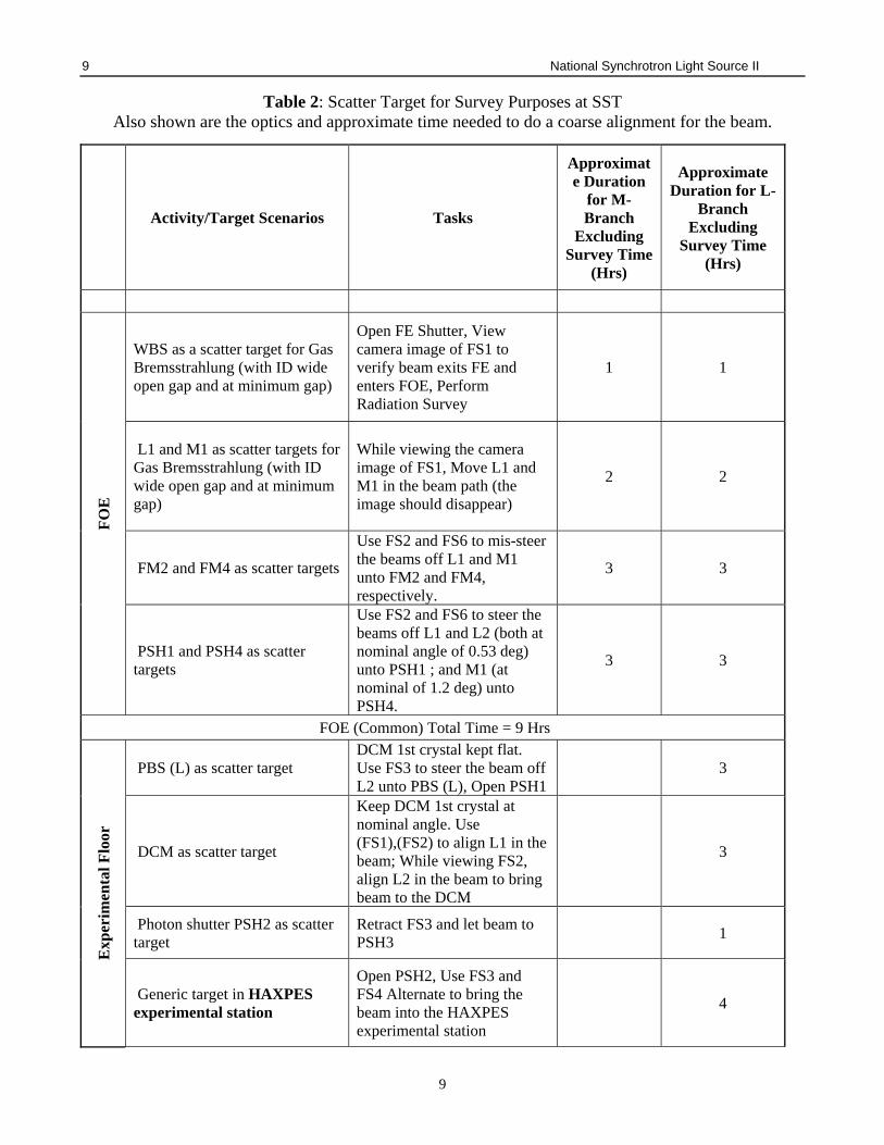
Table 2: Scatter Target for Survey Purposes at SST Also shown are the optics and approximate time needed to do a coarse alignment for the beam.
Activity/Target Scenarios Tasks
Approximate Duration
for M-Branch
Excluding Survey Time
(Hrs)
Approximate Duration for L-
Branch Excluding
Survey Time (Hrs)
FO
E
WBS as a scatter target for Gas Bremsstrahlung (with ID wide open gap and at minimum gap)
Open FE Shutter, View camera image of FS1 to verify beam exits FE and enters FOE, Perform Radiation Survey
1 1
L1 and M1 as scatter targets for Gas Bremsstrahlung (with ID wide open gap and at minimum gap)
While viewing the camera image of FS1, Move L1 and M1 in the beam path (the image should disappear)
2 2
FM2 and FM4 as scatter targets
Use FS2 and FS6 to mis-steer the beams off L1 and M1 unto FM2 and FM4, respectively.
3 3
PSH1 and PSH4 as scatter targets
Use FS2 and FS6 to steer the beams off L1 and L2 (both at nominal angle of 0.53 deg) unto PSH1 ; and M1 (at nominal of 1.2 deg) unto PSH4.
3 3
FOE (Common) Total Time = 9 Hrs
Exp
erim
enta
l Flo
or
PBS (L) as scatter target DCM 1st crystal kept flat. Use FS3 to steer the beam off L2 unto PBS (L), Open PSH1
3
DCM as scatter target
Keep DCM 1st crystal at nominal angle. Use (FS1),(FS2) to align L1 in the beam; While viewing FS2, align L2 in the beam to bring beam to the DCM
3
Photon shutter PSH2 as scatter target
Retract FS3 and let beam to PSH3
1
Generic target in HAXPES experimental station
Open PSH2, Use FS3 and FS4 Alternate to bring the beam into the HAXPES experimental station
4
10 National Synchrotron Light Source II
10
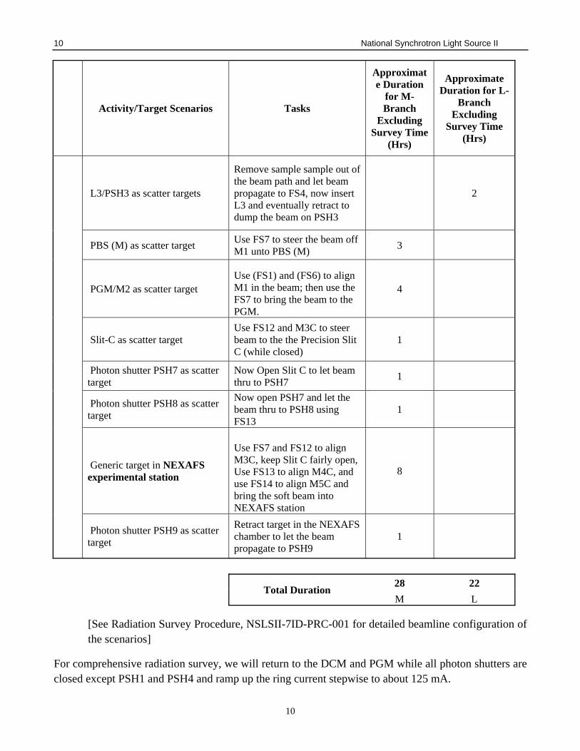
Activity/Target Scenarios Tasks
Approximate Duration
for M-Branch
Excluding Survey Time
(Hrs)
Approximate Duration for L-
Branch Excluding
Survey Time (Hrs)
L3/PSH3 as scatter targets
Remove sample sample out of the beam path and let beam propagate to FS4, now insert L3 and eventually retract to dump the beam on PSH3
2
PBS (M) as scatter target Use FS7 to steer the beam off M1 unto PBS (M)
3
PGM/M2 as scatter target Use (FS1) and (FS6) to align M1 in the beam; then use the FS7 to bring the beam to the PGM.
4
Slit-C as scatter target Use FS12 and M3C to steer beam to the the Precision Slit C (while closed)
1
Photon shutter PSH7 as scatter target
Now Open Slit C to let beam thru to PSH7
1
Photon shutter PSH8 as scatter target
Now open PSH7 and let the beam thru to PSH8 using FS13
1
Generic target in NEXAFS experimental station
Use FS7 and FS12 to align M3C, keep Slit C fairly open, Use FS13 to align M4C, and use FS14 to align M5C and bring the soft beam into NEXAFS station
8
Photon shutter PSH9 as scatter target
Retract target in the NEXAFS chamber to let the beam propagate to PSH9
1
Total Duration 28 22
M L
[See Radiation Survey Procedure, NSLSII-7ID-PRC-001 for detailed beamline configuration of the scenarios]
For comprehensive radiation survey, we will return to the DCM and PGM while all photon shutters are closed except PSH1 and PSH4 and ramp up the ring current stepwise to about 125 mA.

11 National Synchrotron Light Source II
11
C. Finer Alignment/Beam Conditioning/Test Measurements/Calibration
After successfully delivering the beam to the NEXAFS and HAXPES experimental stations; and execution of the radiation survey plan, more precise alignment including some beam conditioning followed by test measurements and energy calibration will be performed.
Purpose: To demonstrate and document an overall baseline performance and calibration (look-up table) of the photon delivery system.
1. Monochromators
a. PGM Energy Calibration at 200 - 1700 eV
a.1 Position the mirrors M1, M3C, M4C and M5C such that they are set to the gold stripe.
a.2 Set M1 to the nominal angle of 1.2º; M3C, M4C and M5C to 1.5º.
a.3 Position the HOPG sample in the NEXAFS chamber in the beam path.
a.4 Select the 250 lines/mm grating of the PGM and perform an energy scan around the C K-edge and monitor and plot the absorption as a function of energy.
a.5 Calibrate the energy of the PGM according to C K-edge and repeat for the Ti foil, TiO2 powder at the TiL- and O K-edges.
a.6 Now select the 600 lines/mm grating of the PGM and perform an energy scan around the O K- and TiL-edges for the Ti foil and TiO2 powder, and Cu L-edge for the Cu foil.
a.7 Verify that the TiL and O K energies are consistent for the two gratings. Repeat Ti L, O K and Cu L edges with selection of the 1200 lines/mm grating and verify that the three energies are consistent between the two gratings.
b. DCMEnergyCalibrationat2200‐7500eV
b.1 Set L2A to gold stripe.
b.2 Get beam to DCM.
b.3 In HAXPES chamber, place a Ti calibration foil between on sample bar and perform an energy scan around the TiK-edge and monitor the absorption as a function of energy. Calibrate the DCM angles according to the K-edge positions.
b.4 With the DCM calibrated against the TiK-edge, repeat above with Fe.
b.5 Calibrate the L1 and L2A angles and set to nominal angle and repeat above for L2A set to the Ni stripe. Compare cut-of energies and re-calibrate angles as needed.
2. Mirrors
a. Align the mirrors and perform beam conditioning while monitoring the vacuum readout.
b. Perform an extensive test (Angular, positional alignment vs. energy) of 4 mirrors (M1, M3C, M4C and M5C) for calibration.

12 National Synchrotron Light Source II
12
c. Change to the nickel stripe in M1 and do an energy scan around the Ti-edge on the Ti foil and TiO2 powder using the 1200 lines/mm grating and determine cut-off energy and compare to the expected cut-off value.
d. Change gold and repeat.
e. Repeat for M3C, M4C and M5C.
D. Characterization and Optimization
Upon completion of energy calibration, characterization and optimization of the photon delivery system will be performed. This will involve a very careful determination and optimization of beam spot size, position, flux, and reproducibility.
Purpose: Demonstrate and document the energy reproducibility and achieve optimized configuration for normal X-ray beam operation.
1. Monochromators
a. DCM Bragg angle reproducibility
b. Tune (111) crystals Bragg angle with energy and optimize at DM1 at estimated max intensity energy.
c. Optimize beam on FS4.
d. [Calibration Refinement if time allows].
e. PGM Energy Reproducibility - verify the energy reproducibility by repeating the following:
e.1 M1, M3C, M4C and M5C set to the gold stripe.
e.2 Set M1 to the nominal angle of 1.2º; M3C, M4C and M5C to 1.5º.
e.3 Position the HOPG sample in the NEXAFS chamber in the beam path.
e.4 Select the 250 lines/mm grating of the PGM and perform an energy scan around the C K-edge.
e.5 Calibrate the energy of the PGM according to C K-edge and repeat for the Ti foil, TiO2 powder at the TiL- and O K-edges.
e.6 Now select the 600 lines/mm grating of the PGM and perform an energy scan around the O K- and TiL-edges for the Ti foil and TiO2 powder, and Cu L-edge for the Cu foil.
e.7 Verify that the TiL and O K energies are consistent between the 250 and 600 lines/mm gratings. Repeat Ti L, O K and Cu L edges with selection of the 1200 lines/mm grating and verify that the three energies are consistent between the two gratings.

13 National Synchrotron Light Source II
13
2. Precision Slit C
Beam conditioning, test measurements and calibration of Precision Slit C to establish proper procedures for identifying the beam size, position, intensity, and energy resolution with different slit size.
3. Diagnostic Modules (In-flange Slits, YAG FS, Intensity Monitors, Pink Beam Stop (for DM1))
a. Perform beam conditioning, characterization of 3 DMs (DM3, DM7 and DM8) to establish proper procedures for identifying the beam size, position, intensity
4. Mirrors
a. Perform beam conditioning of the mirrors (M1, M3C, M4C and M5C).
a.1 Expose the beam to a sacrificial portion of the mirrors and observe the vacuum.
a.2 Close the upstream valves should the pressure rise too quickly to the vacuum warning levels
a.3 Let vacuum stabilize before opening valves/exposing the mirrors to the beam
b. Characterization (Angular, positional alignment vs. Beam size and position) of 4 mirrors (M1, M3C, M4C and M5C).
b.1 At fixed energy, vary the angle of the mirror and measure the beam size and position using the in-flange slits of the diagnostic modules. Repeat for different position of the mirror.
5. Experimental station
a. Perform beam conditioning of the NEXAFS experimental station and determination of beam spot size, position at the station.
b. Verify that the beam is reasonably stable, energy calibrated and reproducible.
c. Verify that M1, M3C, M4C and M5C are set to the gold stripe.
d. Set M1 to the nominal angle of 1.2º; M3C, M4C and M5C to 1.5º.
e. Position the HOPG sample in the NEXAFS chamber in the beam path.
f. Select the 250 lines/mm grating of the PGM and perform an energy scan around the C K-edge.
Below, we provide references which describe in more detail the steps involved in the radiation/technical commissioning with beam.
5.2 Phase II – Scientific Commissioning
The second phase, the science phase which is not part of the scope of this document, will focus on commissioning, in sequence, all the capabilities of the SST complex. This phase will also include
14 National Synchrotron Light Source II
14
guest-assisted commissioning of science experiments. The commissioning plan for this phase will be provided in a separate document.
6 END OF COMMISSIONING: TRANSITION TO OPERATIONS
Commissioning ends when the beamline has shown, through the execution of the procedures and surveys outline in the commissioning plan above, that:
(1) it meets the NSLS-II Shielding Policy,
(2) the radiation leakage or scatter is controlled to as low as reasonably achievable,
(3) the photon beam is prepared for User Operations,
(4) the beamline control system is ready for data collection, and
(5) the necessary authorizations for beginning operations have been obtained.
Prior to the beamlines commencing User Operations, the process outlined in Beamline User Readiness (PS-C-XFD-PRC-030)will be completed.
The safety of ongoing beamline operations will be managed with the Experiment Safety Review (PS-C-ESH-PRC-039) system. A Cognizant Space Manager will be assigned to the area and will have the responsibility of assuring that the system is current and accurate.
Individual experiments will be managed with the electronic SAF section of PASS. Users will identify the materials and equipment they wish to bring along with a task analysis describing how those items will be used. An iterative review between the User, Beamline, and ESH Staff results in a final approval with clear indication of requirements.The SAF process combined with the ESR safety envelope provides the basis needed to assure ongoing control of beamline operation and changes. No additional readiness reviews are expected for the 7-ID beamline at this time.
7 REFERENCES
1. PS-C-XFD-PRC-008, Synchrotron and Bremsstrahlung Ray Trace Procedure
2. PS-C-ASD-PRC-147, Insertion Device Front End Ray Tracing Procedure
3. NSLSII-TOS-RPT-016, Beamline 7-ID (SST) Top-Off Radiation Safety Analysis
4. Tech Note 275, Preliminary 07-ID SST Beamline Radiation Shielding Analysis
5. PS-C-XFD-PRC-003,Enabling Beamlines for Operations
6. PS-C-ESH-PRC-039, Experiment Safety Review

15 National Synchrotron Light Source II
15
7. PS-C-CMD-PLN-001, NSLS-II Process Description: Review Process for Facility Additions and
Modifications
8. NSLSII-7ID-PRC-001, Beamline 7-ID Radiation Survey Procedure
9. PS-C-XFD-PRC-004, NSLS-II Beamlines Radiation Safety Commissioning Plan
10. PS-C-XFD-PRC-030, Beamline User Readiness
16 National Synchrotron Light Source II
16
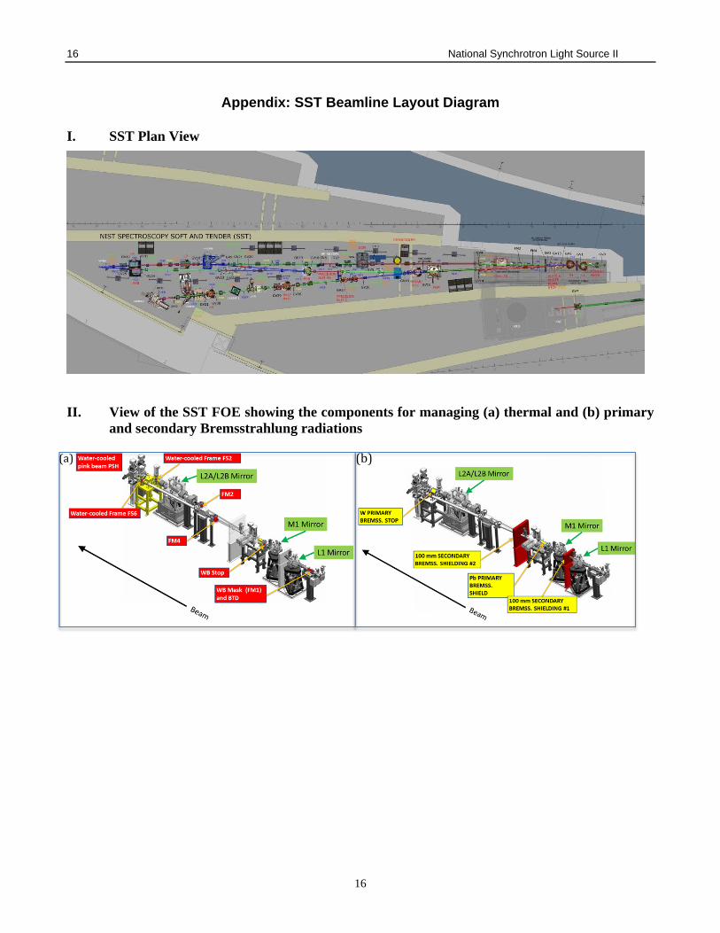
Appendix: SST Beamline Layout Diagram
I. SST Plan View
II. View of the SST FOE showing the components for managing (a) thermal and (b) primary
and secondary Bremsstrahlung radiations
(a) (b)
17 National Synchrotron Light Source II
17
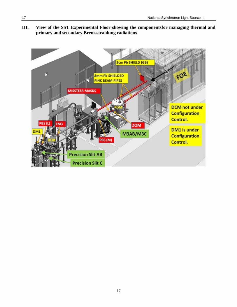
III. View of the SST Experimental Floor showing the componentsfor managing thermal and primary and secondary Bremsstrahlung radiations


