108
MPW-1 TDM Pseudowire Access Gateway MP-4100 Version 2.0 INSTALLATION AND OPERATION MANUAL The Access Company

MPW-1TDM Pseudowire Access Gateway
MP-4100 Version 2.0
INSTA
LLATIO
N A
ND
O
PER
ATIO
N M
AN
UA
L
The Access Company


MPW-1 TDM Pseudowire Access Gateway
MP-4100 Version 2.0
Installation and Operation Manual
Notice
This manual contains information that is proprietary to RAD Data Communications Ltd. ("RAD"). No part of this publication may be reproduced in any form whatsoever without prior written approval by RAD Data Communications.
Right, title and interest, all information, copyrights, patents, know-how, trade secrets and other intellectual property or other proprietary rights relating to this manual and to the MPW-1 and any software components contained therein are proprietary products of RAD protected under international copyright law and shall be and remain solely with RAD.
The MPW-1 product name is owned by RAD. No right, license, or interest to such trademark is granted hereunder, and you agree that no such right, license, or interest shall be asserted by you with respect to such trademark. The RAD name, logo, logotype, and the terms EtherAccess, TDMoIP and TDMoIP Driven, and the product names Optimux and IPmux, are registered trademarks of RAD Data Communications Ltd. All other trademarks are the property of their respective holders.
You shall not copy, reverse compile or reverse assemble all or any portion of the Manual or the MPW-1. You are prohibited from, and shall not, directly or indirectly, develop, market, distribute, license, or sell any product that supports substantially similar functionality as the MPW-1, based on or derived in any way from the MPW-1. Your undertaking in this paragraph shall survive the termination of this Agreement.
This Agreement is effective upon your opening of the MPW-1 package and shall continue until terminated. RAD may terminate this Agreement upon the breach by you of any term hereof. Upon such termination by RAD, you agree to return to RAD the MPW-1 and all copies and portions thereof.
For further information contact RAD at the address below or contact your local distributor.
International Headquarters RAD Data Communications Ltd.
24 Raoul Wallenberg Street Tel Aviv 69719, Israel Tel: 972-3-6458181 Fax: 972-3-6498250, 6474436 E-mail: [email protected]
North America Headquarters RAD Data Communications Inc.
900 Corporate Drive Mahwah, NJ 07430, USA Tel: (201) 5291100, Toll free: 1-800-4447234 Fax: (201) 5295777 E-mail: [email protected]
© 2007–2008 RAD Data Communications Ltd. Publication No. 464-202-12/08


MPW-1 MP-4100 Ver. 2.0 1
Quick Start Guide
If you are familiar with the MPW-1 modules, use this guide to prepare it for operation.
SFPs installed on MPW-1 modules may be equipped with a laser diode. In such cases, a label with the laser class and other warnings as applicable will be attached near the optical transmitter. The laser warning symbol may be also attached.
For your safety:
• Before turning on the equipment, make sure that the fiber optic cable is intact and is connected to the optical transmitter.
• Do not use broken or unterminated fiber-optic cables/connectors.
• Do not look straight at the laser beam, and do not look directly into the optical connectors while the module is operating.
• Do not attempt to adjust the laser drive current.
• The use of optical instruments with this product will increase eye hazard. Laser power up to 1 mW could be collected by an optical instrument.
• Use of controls or adjustment or performing procedures other than those specified herein may result in hazardous radiation exposure.
ATTENTION: The laser beam may be invisible!
Preparations for Operation
1. If necessary, install the prescribed SFPs in the MPW-1 SFP sockets.
2. Insert the module in the assigned I/O slot.
3. Refer to the site installation plan, identify the cables intended for connection to the MPW-1 connectors, and connect the cables as explained below.
Connecting Cables to Ethernet Ports
To connect cables to the optical Ethernet ports:
1. Connect each prescribed cable to the corresponding MPW-1 connector, ETH1, ETH2 or ETH3. When two fibers are used, pay attention to connector polarity: the transmitter output is at left-hand side.
Connecting Cables to Electrical Ethernet Ports
To connect cables to the MPW-1 electrical Ethernet ports:
1. Connect the prescribed cable to the corresponding connector, ETH1, ETH2, or ETH3.
Warning

Quick Start Guide Installation and Operation Manual
2 MPW-1 MP-4100 Ver. 2.0
Configuring Physical Layer Parameters
Configuring Internal DS1 Ports Physical Layer Parameters
For the supervision terminal, use the Configuration > Physical Layer > I/O screen.
Parameter Values Parameter Values
Port Number 1 to 8 Wait to Restore 0 to 999 seconds
Administrative
Status
DOWN
UP
Cross Connect DS0 (framed modes only)
DS1
Name Up to 32 alphanumeric
characters
Destination Slot
(DS1 cross-connect
mode only)
CL
IO-1 to IO-10
Redundancy NONE
DUAL CABLE P.TX
Destination Port
(DS1 cross-connect
mode only)
E1 or T1 external or internal
ports: 1 to 8
DS1 ports: 1 to 8
STM-1 PDH ports: 1 to 63 for
OC-3 PDH ports: 1 to 84
Primary
(when Redundancy
is DUAL CABLE P.TX)
YES
NO
Framing FRAMED
UNFRAMED
Redundant Slot
(when Redundancy
is DUAL CABLE P.TX)
CL
I/O-1 to I/O-10
Signaling NO
YES
Redundant Port
(when Redundancy
is DUAL CABLE P.TX)
E1 or T1 external or internal
ports: 1 to 8
DS1 ports: 1 to 8
STM-1 PDH ports: 1 to 63 for
OC-3 PDH ports: 1 to 84
Configuring Internal DS1 Port Timeslot Utilization
For framed internal DS1 ports using the DS0 cross-connect mode, configure timeslot assignment (including timeslots using split assignment).
For the supervision terminal, use the last item, Time Slot Assignment, on the Configuration > Physical Layer > I/O screen of the desired MPW-1 internal DS1 port, or use the Configuration > System > TS Assignment screen in accordance with the information appearing in the Megaplex-4100 Installation and Operation Manual.

Installation and Operation Manual Quick Start Guide
MPW-1 MP-4100 Ver. 2.0 3
Configuring Ethernet Ports Physical Layer Parameters
For the supervision terminal, use the Configuration > Physical Layer > I/O screen.
Parameter Values Parameter Values
Port Number 1 to 3
All Ports
Auto Negotiation ENABLE
DISABLE
Administrative
Status
DOWN
UP
Max. Capability
Advertised
(autonegotiation
enabled)
10Mbps half duplex
10Mbps full duplex
100Mbps half duplex
100Mbps full duplex
Name Up to 32 alphanumeric
characters
Speed & Duplex
(autonegotiation
disabled)
10Mbps half duplex
10Mbps full duplex
100Mbps half duplex
100Mbps full duplex
Configuring the General Router Parameters
For the supervision terminal, use the Configuration > Applications > Router > Interface screen.
Parameter Values
Default Gateway Valid IP address in the subnet of one of the router
interfaces, in dotted-quad notation
ARP Aging Time 300 to 1000000 sec
Configuring the Router Interfaces
For the supervision terminal, use the Configuration > Applications > Router screen.
Parameter Values Parameter Values
Number 1 to 100 Slot I/O-1 to I/O-10
CL-A and CL-B
Name Up to 32 alphanumeric characters Port I/O modules with Ethernet ports: ETH
port (ETH-1, ETH-2 or ETH-3)
CL.1/GbE modules: GbE-1 and GbE-2
CL.1/155GbE modules: GbE-1, GbE-2,
and VCG1 to VCG8
IP address Valid IP address in dotted-quad
notation
VLAN Tagging DISABLE
ENABLE
IP Mask Valid IP subnet mask in dotted-quad
notation
VLAN ID 1 to 4094
Quick Start Guide Installation and Operation Manual
4 MPW-1 MP-4100 Ver. 2.0
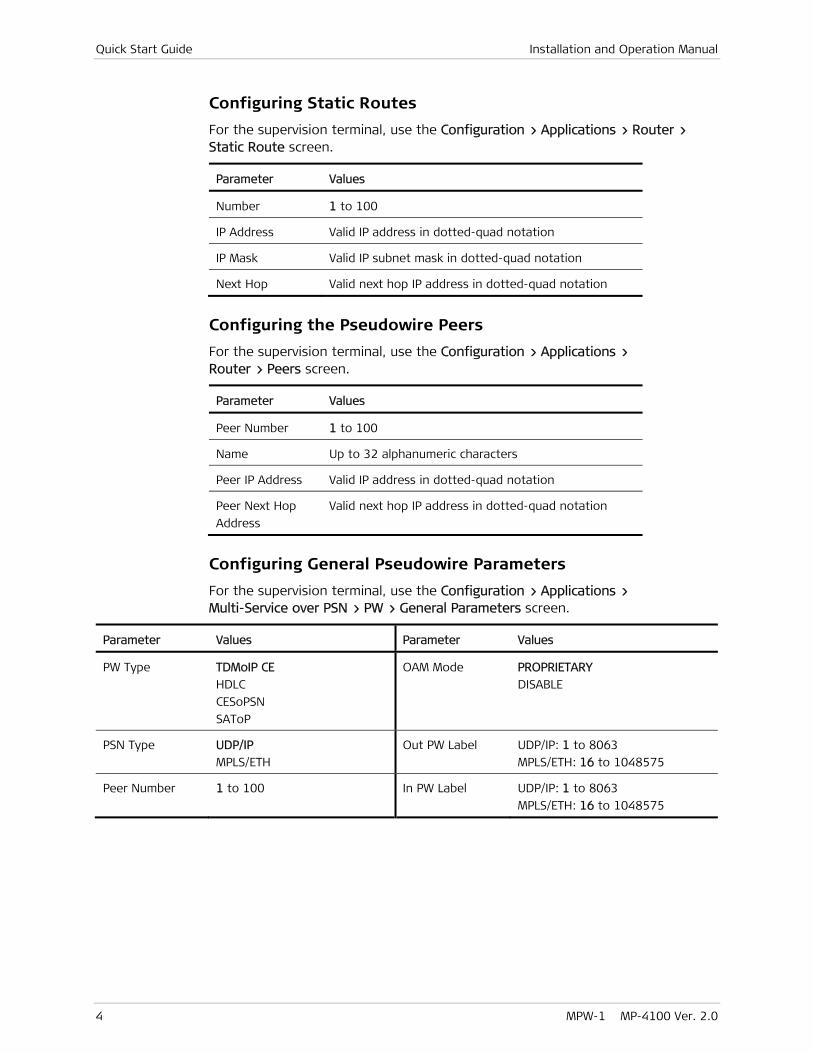
Configuring Static Routes
For the supervision terminal, use the Configuration > Applications > Router > Static Route screen.
Parameter Values
Number 1 to 100
IP Address Valid IP address in dotted-quad notation
IP Mask Valid IP subnet mask in dotted-quad notation
Next Hop Valid next hop IP address in dotted-quad notation
Configuring the Pseudowire Peers
For the supervision terminal, use the Configuration > Applications > Router > Peers screen.
Parameter Values
Peer Number 1 to 100
Name Up to 32 alphanumeric characters
Peer IP Address Valid IP address in dotted-quad notation
Peer Next Hop
Address
Valid next hop IP address in dotted-quad notation
Configuring General Pseudowire Parameters
For the supervision terminal, use the Configuration > Applications > Multi-Service over PSN > PW > General Parameters screen.
Parameter Values Parameter Values
PW Type TDMoIP CE
HDLC
CESoPSN
SAToP
OAM Mode PROPRIETARY
DISABLE
PSN Type UDP/IP
MPLS/ETH
Out PW Label UDP/IP: 1 to 8063
MPLS/ETH: 16 to 1048575
Peer Number 1 to 100 In PW Label UDP/IP: 1 to 8063
MPLS/ETH: 16 to 1048575
Installation and Operation Manual Quick Start Guide
MPW-1 MP-4100 Ver. 2.0 5
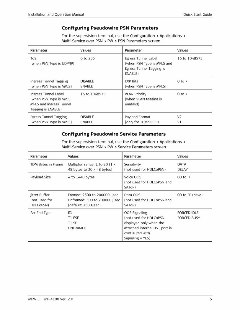
Configuring Pseudowire PSN Parameters
For the supervision terminal, use the Configuration > Applications > Multi-Service over PSN > PW > PSN Parameters screen.
Parameter Values Parameter Values
ToS
(when PSN Type is UDP/IP)
0 to 255 Egress Tunnel Label
(when PSN Type is MPLS and
Egress Tunnel Tagging is
ENABLE)
16 to 1048575
Ingress Tunnel Tagging
(when PSN Type is MPLS)
DISABLE
ENABLE
EXP Bits
(when PSN Type is MPLS)
0 to 7
Ingress Tunnel Label
(when PSN Type is MPLS
MPLS and Ingress Tunnel
Tagging is ENABLE)
16 to 1048575 VLAN Priority
(when VLAN tagging is
enabled)
0 to 7
Egress Tunnel Tagging
(when PSN Type is MPLS)
DISABLE
ENABLE
Payload Format
(only for TDMoIP CE)
V2
V1
Configuring Pseudowire Service Parameters
For the supervision terminal, use the Configuration > Applications > Multi-Service over PSN > PW > Service Parameters screen.
Parameter Values Parameter Values
TDM Bytes in Frame Multiplier range: 1 to 30 (1 ×
48 bytes to 30 × 48 bytes)
Sensitivity
(not used for HDLCoPSN)
DATA
DELAY
Payload Size 4 to 1440 bytes Voice OOS
(not used for HDLCoPSN and
SAToP)
00 to FF
Jitter Buffer
(not used for
HDLCoPSN)
Framed: 2500 to 200000 μsec
Unframed: 500 to 200000 μsec
(default: 2500μsec)
Data OOS
(not used for HDLCoPSN and
SAToP)
00 to FF (hexa)
Far End Type E1
T1 ESF
T1 SF
UNFRAMED
OOS Signaling
(not used for HDLCoPSN;
displayed only when the
attached internal DS1 port is
configured with
Signaling = YES)
FORCED IDLE
FORCED BUSY

Quick Start Guide Installation and Operation Manual
6 MPW-1 MP-4100 Ver. 2.0
Configuring Attachment Circuit Parameters
For the supervision terminal, use the Configuration > Applications > Multi-Service over PSN > PW > Service Parameters > Attachment Circuit screen.
Parameter Values
Slot IO-1 to IO-10
Int DS1 Number 1 to 8
Time Slots See below
Selecting Timeslots Connected to a Pseudowire
For each pseudowire connected to an internal DS1 port using the DS0 cross-connect mode, configure timeslot assignment.
For the supervision terminal, use the Configuration > Applications > Multi-Service over PSN > PW > Service Parameters > Time Slots screen.
Configuring Pseudowires as System Timing References
1. For the supervision terminal, use the Configuration > System > Clock Source > Recovered screen to specify the pseudowire that can be used as system timing references.
Parameter Values Parameter Values
Slot I/O-1 to I/O-10 Administrative
Status
DOWN
UP
Type ADAPTIVE Source Quality STRATUM 1 (not supported)
STRATUM 2 (not supported)
STRATUM 3
STRATUM 3E
STRATUM 4
ID 1 to 20 Network Type Type B
Type A
PW Number 1 to 640
2. Use the Configuration > System > Clock Source screen to include the required pseudowires as timing reference sources, in accordance with the information appearing in the Megaplex-4100 Installation and Operation Manual.

MPW-1 MP-4100 Ver. 2.0 i
Contents
Chapter 1. Introduction
1.1 Overview.................................................................................................................... 1-1 Product Options ...................................................................................................... 1-1 Applications ............................................................................................................ 1-2 Features ................................................................................................................. 1-4
1.2 Physical Description ................................................................................................... 1-7 1.3 Functional Description ................................................................................................ 1-8
TDM Subsystem ...................................................................................................... 1-9 TDM and Signaling Bus Interfaces ....................................................................... 1-9 TDM Cross-Connect Matrix .................................................................................. 1-9 Internal DS1 Ports ............................................................................................ 1-10
Pseudowire Cross-Connect Matrix ......................................................................... 1-11 Packet Processing Subsystem ................................................................................ 1-11
TDMoPSN Processing ........................................................................................ 1-12 HDLCoPSN Processing ...................................................................................... 1-13 SAToPSN Processing ......................................................................................... 1-13 CESoPSN Processing ......................................................................................... 1-14 Jitter Buffer Functions ...................................................................................... 1-14 Adaptive Timing ............................................................................................... 1-15 OAM Protocol ................................................................................................... 1-16 PSN Configuration Parameters .......................................................................... 1-17
Ethernet Subsystem .............................................................................................. 1-17 External Ethernet Ports .................................................................................... 1-17 Ethernet Layer 2 Switch Capabilities ................................................................. 1-19 Ethernet Termination and Processing ............................................................... 1-20
Controlling Pseudowire Routing ............................................................................. 1-20 Redundancy .......................................................................................................... 1-21
Redundancy via PSN only .................................................................................. 1-22 Redundancy via PSN and TDM (E1) Networks .................................................... 1-23
Application Guidelines ........................................................................................... 1-23 Bandwidth Utilization Considerations ................................................................ 1-23 Determining UDP Port Numbers Used by Pseudowires ....................................... 1-25
MPW-1 Timing Subsystem ..................................................................................... 1-26 MPW-1 Local Management Subsystem ................................................................... 1-26 MPW-1 Diagnostic Functions ................................................................................. 1-26
1.4 Technical Specifications ............................................................................................ 1-27
Chapter 2. Installation
2.1 Installing the Module .................................................................................................. 2-1 Preparations for Installation .................................................................................... 2-1
Installing an SFP ................................................................................................. 2-2 Replacing an SFP ................................................................................................ 2-3
Module Installation Procedure ................................................................................. 2-3 2.2 Connecting to MPW-1 Modules ................................................................................... 2-4
Connecting User’s Equipment to MPW-1 Ethernet Ports ........................................... 2-4 Connecting Users’ Equipment to Electrical Ethernet Ports ........................................ 2-4

Table of Contents Installation and Operation Manual
ii MPW-1 MP-4100 Ver. 2.0
Chapter 3. Configuration
3.1 Normal Indications ..................................................................................................... 3-3 3.2 Default Settings ......................................................................................................... 3-3 3.3 Putting a New MPW-1 Module in Service ..................................................................... 3-7
Adding an MPW-1 to Megaplex-4100 Database ....................................................... 3-7 Configuring the Internal DS1 Ports .......................................................................... 3-7
Configuring Physical Layer Parameters of Internal DS1 Ports ............................... 3-7 Redundancy Configuration Guidelines ............................................................... 3-10 Configuring Internal DS1 Port Timeslot Utilization ............................................. 3-11 Configuring Internal DS1 Port Connections ........................................................ 3-12
Configuring Physical Layer Parameters of Ethernet Ports ....................................... 3-12 3.4 Configuring Pseudowire Services .............................................................................. 3-14
Configuring the Router Function to Support Pseudowire Services .......................... 3-14 Configuring the General Router Parameters ...................................................... 3-15 Configuring Router Interfaces ........................................................................... 3-16 Configuring Static Routes ................................................................................. 3-18 Configuring the Pseudowire Peers .................................................................... 3-19
Pseudowire Parameters Configuration Sequence ................................................... 3-20 Preliminary Configuration Steps ........................................................................ 3-21 Configuring General Pseudowire Parameters ..................................................... 3-21 Configuring Pseudowire PSN Parameters ........................................................... 3-23 Configuring Pseudowire Service Parameters and Attachment Circuit Parameters 3-26 Selecting Internal DS1 Timeslots Connected to a Pseudowire ............................ 3-29
Configuring Fault Propagation for MPW-1 Modules ................................................ 3-30 3.5 Configuring Pseudowires as System Timing References ............................................. 3-31 3.6 Viewing Ethernet Flows Associated with Pseudowires ............................................... 3-33
Chapter 4. Troubleshooting and Diagnostics
4.1 Monitoring Performance ............................................................................................. 4-1 Monitoring Ethernet Ports ....................................................................................... 4-2 Monitoring Pseudowire Services .............................................................................. 4-6
Displaying Pseudowire Status Data ..................................................................... 4-6 Displaying Pseudowire Diagnostic Statistics ........................................................ 4-7 Displaying Pseudowire Transmission Statistics .................................................. 4-10
Monitoring Internal DS1 Port Status ...................................................................... 4-11 Monitoring the Timing Source Status ..................................................................... 4-11
4.2 Detecting Configuration Errors ................................................................................. 4-13 4.3 Handling Alarms ....................................................................................................... 4-16 4.4 Troubleshooting ....................................................................................................... 4-18 4.5 Diagnostic Functions ................................................................................................ 4-19
Local Loopback on Selected Internal DS1 Port Timeslots ........................................ 4-19 Remote Loopback on Selected Internal DS1 Port Timeslots .................................... 4-21 Ping Test .............................................................................................................. 4-22
4.6 Technical Support .................................................................................................... 4-23

MPW-1 MP-4100 Ver. 2.0 Overview 1-1
Chapter 1
Introduction
1.1 Overview
This manual describes the technical characteristics, applications, installation and operation of the MPW-1 pseudowire access gateway I/O module for the Megaplex-4100 Next Generation Multiservice Access Node.
MPW-1 operates as a pseudowire server for TDM traffic (E1, T1, SHDSL, ISDN, high-speed and low-speed data, voice) received via the internal Megaplex-4100 TDM buses from other I/O modules installed in the same chassis. MPW-1 performs the following tasks:
• Interfacing to the Megaplex-4100 internal TDM buses (equivalent capacity of 256 timeslots, or eight 2.048 Mbps streams).
• Conversion between TDM and pseudowire packet formats. The conversion parameters are controlled by defining pseudowires (see Megaplex-4100 Installation and Operation Manual for details), and can be optimized for the specific end-user’s equipment and the application requirements.
• Forwarding the pseudowire packet streams, either directly to a PSN (through the MPW-1 external Fast Ethernet ports, or via its internal Fast Ethernet ports), for forwarding over any bridge port within the Megaplex-4100 (refer to the Megaplex-4100 Installation and Operation Manual for details). Each pseudowire can be forwarded to the desired endpoint through the packet-switched network. Both UDP/IP and MPLS/ETH networks are supported. The user can also specify forwarding and priority/quality of service parameters.
Installing a MPW-1 module enhances Megaplex-4100 capabilities and services by enabling the transport of legacy TDM traffic from other modules over Ethernet, IP, and MPLS packet-switched networks (PSNs), even when the Megaplex-4100 is not equipped with CL modules with GbE ports. MPW-1 supports the TDMoIP, CESoPSN, SAToP and HDLCoPSN pseudowire protocols.
For details regarding the integration of MPW-1 modules in Megaplex-4100 systems and systems applications, refer to the Megaplex-4100 Installation and Operation Manual.
Product Options
MPW-1 is a pseudowire access gateway module with two types of ports:
• Internal TDM (DS1) ports, for TDM traffic from the internal TDM buses of the Megaplex-4100
• Internal and external Fast Ethernet ports, for the packetized data streams.
Chapter 1 Introduction Installation and Operation Manual
1-2 Overview MPW-1 MP-4100 Ver. 2.0
MPW-1 is offered in two models with similar characteristics, which differ only in the type of interfaces supported by the external Fast Ethernet ports:
• MPW-1/UTP: has three 10/100BASE-TX interfaces terminated in RJ-45 connectors
• MPW-1/SFP: has three sockets for Fast Ethernet SFP optical transceivers. RAD offers several types of SFPs capable of meeting a wide range of operational requirements.
Applications
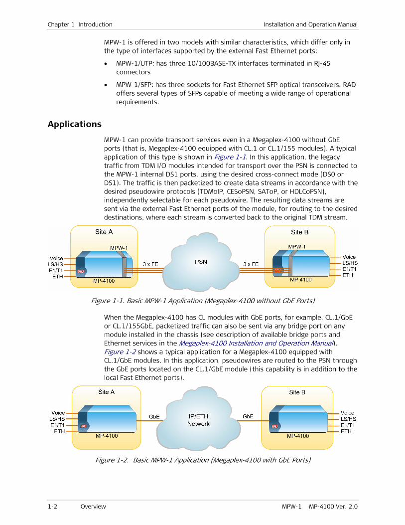
MPW-1 can provide transport services even in a Megaplex-4100 without GbE ports (that is, Megaplex-4100 equipped with CL.1 or CL.1/155 modules). A typical application of this type is shown in Figure 1-1. In this application, the legacy traffic from TDM I/O modules intended for transport over the PSN is connected to the MPW-1 internal DS1 ports, using the desired cross-connect mode (DS0 or DS1). The traffic is then packetized to create data streams in accordance with the desired pseudowire protocols (TDMoIP, CESoPSN, SAToP, or HDLCoPSN), independently selectable for each pseudowire. The resulting data streams are sent via the external Fast Ethernet ports of the module, for routing to the desired destinations, where each stream is converted back to the original TDM stream.
Figure 1-1. Basic MPW-1 Application (Megaplex-4100 without GbE Ports)
When the Megaplex-4100 has CL modules with GbE ports, for example, CL.1/GbE or CL.1/155GbE, packetized traffic can also be sent via any bridge port on any module installed in the chassis (see description of available bridge ports and Ethernet services in the Megaplex-4100 Installation and Operation Manual). Figure 1-2 shows a typical application for a Megaplex-4100 equipped with CL.1/GbE modules. In this application, pseudowires are routed to the PSN through the GbE ports located on the CL.1/GbE module (this capability is in addition to the local Fast Ethernet ports).
Figure 1-2. Basic MPW-1 Application (Megaplex-4100 with GbE Ports)
Installation and Operation Manual Chapter 1 Introduction
MPW-1 MP-4100 Ver. 2.0 Overview 1-3
The application of Figure 1-2 also permits users connected to MPW-1 Ethernet ports access to packet switched networks (PSN), for example, Internet or metropolitan Ethernet networks, via the Megaplex-4100GbE links.
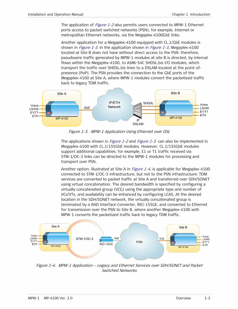
Another application for a Megaplex-4100 equipped with CL.1/GbE modules is shown in Figure 1-3. In the application shown in Figure 1-3, Megaplex-4100 located at Site B does not have without direct access to the PSN: therefore, pseudowire traffic generated by MPW-1 modules at site B is directed, by internal flows within the Megaplex-4100, to ASMi-54C SHDSL.bis I/O modules, which transport the traffic over SHDSL.bis lines to a DSLAM located at the point-of-presence (PoP). The PSN provides the connection to the GbE ports of the Megaplex-4100 at Site A, where MPW-1 modules convert the packetized traffic back to legacy TDM traffic.
Figure 1-3. MPW-1 Application Using Ethernet over DSL
The applications shown in Figure 1-2 and Figure 1-3 can also be implemented in Megaplex-4100 with CL.1/155GbE modules. However, CL.1/155GbE modules support additional capabilities: for example, E1 or T1 traffic received via STM-1/OC-3 links can be directed to the MPW-1 modules for processing and transport over PSN.
Another option, illustrated at Site A in Figure 1-4, is applicable for Megaplex-4100 connected to STM-1/OC-3 infrastructure, but not to the PSN infrastructure: TDM services are converted to packet traffic at Site A and transferred over SDH/SONET using virtual concatenation. The desired bandwidth is specified by configuring a virtually concatenated group (VCG) using the appropriate type and number of VCs/VTs, and availability can be enhanced by configuring LCAS. At the desired location in the SDH/SONET network, the virtually concatenated group is terminated by a RAD Interface Converter, RICi-155GE, and converted to Ethernet for transmission over the PSN to Site B, where another Megaplex-4100 with MPW-1 converts the packetized traffic back to legacy TDM traffic.
Figure 1-4. MPW-1 Application – Legacy and Ethernet Services over SDH/SONET and Packet Switched Networks

Chapter 1 Introduction Installation and Operation Manual
1-4 Overview MPW-1 MP-4100 Ver. 2.0
Features
MPW-1 is a pseudowire server I/O module that provides TDM pseudowire access gateway services over packet-switched networks (Ethernet, IP, and MPLS) for TDM traffic (E1, T1, SHDSL, ISDN, high-speed and low-speed data, voice) received via the Megaplex-4100 TDM buses from other modules. The MPW-1 module has eight independently-configurable internal DS1 ports, each capable of handling 32 timeslots, for a total processing capacity of 256 timeslots (the equivalent of 8 E1, or 2.048 Mbps, streams). Multiple MPW-1 modules can be installed in the Megaplex-4100 chassis, in accordance with the required pseudowire transport capacity.
The MPW-1 module provides pseudowire emulation services over packet-switched networks using the following user-configurable protocols:
• TDMoIP (TDM over IP) in accordance with RFC5087, and TDMoMPLS in accordance with RFC5087 and ITU-T Rec. Y.1413
• HDLCoPSN (HDLC over PSN) in accordance with RFC5087 and RFC4618 (except Clause 5.3 – PPP)
• CESoPSN (structure-aware TDM circuit emulation over PSN) in accordance with RFC5086
• SAToPSN (structure-agnostic TDM over PSN) in accordance with RFC4553
MPW-1 meets the requirements for edge-to-edge simulation of TDM circuits over PSN in accordance with RFC4197, including high-performance adaptive timing recovery capabilities. Pseudowires of all types, except HDLCoPSN, can be selected as timing sources for the Megaplex-4100 nodal timing subsystem.
The number of pseudowires supported by each MPW-1 internal DS1 port depends on the payload framing mode:
• Each framed internal DS1 port can be served by up to 16 pseudowires, where each pseudowire can be separately routed to its desired destination over the PSN, for a total of 128 destinations per module. The total number of pseudowires is up to 640 per Megaplex-4100 chassis.
The actual number of active pseudowires depends on internal DS1 port timeslot assignment (a timeslot can be included in a single pseudowire). An internal cross-connect matrix, similar in capabilities to the cross-connect matrices in other I/O modules, provides full control over timeslot routing from any TDM port within the Megaplex-4100 to the desired pseudowire, independently for each port, using either DS0 or DS1 cross-connect mode.
• An unframed E1 or T1 port is served by a single pseudowire (in this case, only the DS1 cross-connect mode can be used).
Each pseudowire terminated on the MPW-1 can be independently configured to handle the desired type of traffic:
• Transparent transfer of data (unframed E1 streams) using TDMoPSN, or SAToPSN
• Transfer of framed E1 and T1 streams, using TDMoPSN and CESoPSN.
To support voice payload, the signaling information can also be transported. Note that when using CESoPSN, any timeslots carrying signaling information (either channel-associated signaling (CAS), or common-channel signaling
Installation and Operation Manual Chapter 1 Introduction
MPW-1 MP-4100 Ver. 2.0 Overview 1-5
(CCS) such as Signaling Scheme 7 (SS7), ISDN PRI signaling, etc.) can be transparently transferred within the pseudowire, as regular data timeslots.
• Fractional E1 and T1 services, with or without CAS, are supported by means of TDMoPSN. Without CAS, CESoPSN can also be used.
• HDLC traffic can be carried over framed and unframed E1 and T1 using HDLCoPSN. This enables efficient and transparent transfer of Frame Relay traffic.
Packet structure is independently selectable for each pseudowire, for compatibility with the various pseudowire protocols (TDMoPSN, CESoPSN, HDLCoPSN, SAToPSN) and the PSN type (UDP/IP or MPLS/ETH). For maximum flexibility in system applications, the framing format of the pseudowire device at the destination (referred to as a pseudowire peer) can also be taken into account, thus in many cases traffic using the E1 standards can be directed at destinations using the T1 standards, and vice versa.
The pseudowire exit port toward the PSN is also selectable: either via one of the MPW-1 Ethernet ports, or, when Megaplex-4100 is equipped with GbE ports, via any other bridge port (GbE, Fast Ethernet, or VCG) of any module installed in the chassis. The selectable exit ports are configured as router interfaces, where each router interface has its own IP source address, and optionally – its own VLAN (each MPW-1 module supports up 6 interfaces, for a maximum of 100 router interfaces per Megaplex-4100). The user can also specify static routes to control the IP routing.
The internal MPW-1 Ethernet subsystem is based on an Ethernet switch with built-in flow classification engine, and support for VLAN tagging according to IEEE 802.1Q and 802.1p. The Ethernet switch switches traffic among the module Ethernet ports and the pseudowire engine, and, when a CL module with GbE ports is installed in the Megaplex-4100 – also to the Ethernet traffic subsystem of the CL module (for connection via any other bridge port in the Megaplex-4100, via the CL GbE ports to a packet-switched network, or for transmission through the SDH/SONET network via virtually concatenated groups). The internal Ethernet switch also enables connecting MPW-1 Ethernet ports to the Megaplex-4100 management flow.
MPW-1 supports the OAM mechanism for connectivity verification, and pseudowire configuration mismatch prevention. MPW-1 also supports a wide range of performance monitoring statistics to enable analyzing transmission problems and optimizing PSN transmission performance.
To enable optimal handling of pseudowire traffic within the PSN, the following parameters can be configured:
• For Ethernet transport networks: outgoing pseudowire packets are assigned to a dedicated VLAN ID according to 802.1Q and marked for priority using 802.1p bits.
• For IP transport networks: outgoing pseudowire packets are marked for priority using DSCP, ToS, or Diffserv bits. This allows TDMoIP packets to be given the highest priority in IP networks.
• For MPLS transport networks: outgoing pseudowire packets are assigned to a specific MPLS tunnel, and marked for priority using the EXP bits.

Chapter 1 Introduction Installation and Operation Manual
1-6 Overview MPW-1 MP-4100 Ver. 2.0
The proper balance between the PSN throughput and delay is achieved via configurable packet size. A jitter buffer with selectable size compensates for packet delay variation (jitter) of up to 200 msec in the network.
On the TDM side, MPW-1 timing is locked to the Megaplex-4100 nodal timing, because its traffic is synchronously collected from Megaplex-4100 TDM buses, and the received traffic is also deposited on these buses. Each pseudowire has its own adaptive timing recovery mechanism, in accordance with the options listed in RFC4197. The recovered pseudowire clocks can be used as timing reference signals for the nodal Megaplex-4100 timing subsystem, and therefore MPW-1 allows flexible timing distribution.
The MPW-1 module supports 1:1 redundancy protection between internal DS1 ports, and between an internal DS1 port and a user-selected legacy TDM port (E1, T1, SHDSL, PDH, etc.) with redundancy. To minimize traffic when a pseudowire it is not active due to the redundancy mechanism, the pseudowire transmits only OAM packets to ensure connectivity.
The MPW-1 module operating parameters are determined by commands received from the Megaplex-4100 CL module. The CL module can also download new software to the module, when the Megaplex-4100 software is updated.
The module supports comprehensive diagnostics, including power-up self-test, and local and remote loopbacks for each port. Front-panel indicators indicate at a glance the status of Ethernet module ports.

Installation and Operation Manual Chapter 1 Introduction
MPW-1 MP-4100 Ver. 2.0 Physical Description 1-7
1.2 Physical Description
The MPW-1 module occupies one I/O slot in the Megaplex-4100 chassis. Typical panels are shown in Figure 1-5.
Figure 1-5. Typical Module Panels
MPW-1
LASERCLASS
1
ETH1
ETH2
TXRX
ETH3
TXRX
TXRX
ETH1ETH2
LINK ACT
MPW-1
LINK
ETH1
ACT
LINK
ACT
LINK
ACTETH2
ETH3
Module with Ethernet Ports Equipped with
SFPs
Module with Copper Ethernet Ports
The MPW-1 panel includes three Ethernet ports, designated ETH1, ETH2 and ETH3. The ports are equipped either with SFPs, or terminated in RJ-45 connectors.
Each port has its own set of ACT and LINK status indicators, except for the ETH3 port, when equipped with SFP.
The functions of the ETH port status indicator are as follows:
• ACT (yellow): flashes in accordance with the transmit and/or receive activity on the corresponding port
• LINK (green): lights when the link integrity signal is detected by the corresponding port (normal operating condition).

Chapter 1 Introduction Installation and Operation Manual
1-8 Functional Description MPW-1 MP-4100 Ver. 2.0
1.3 Functional Description
Figure 1-6 shows the functional block diagram of the MPW-1 module.
........
LocalManagement
MPW-1
TDMCross-Connect
Matrix
SignalingBus
Interface
TDM BusInterface
TDM
Bus
Sign
alin
g B
us
EthernetSwitchingSubsystem
EthernetTransceiver
EthernetTransceiver
EthernetTransceiver
ETH1
ETH2
ETH3
EthernetTermination
and Processing
Fast Ethernet Traffic Bus
Fast Ethernet Management Bus
Control
Man
agem
ent B
us
Timing andClock Signals
InternalTiming
Generator
InternalClock & TimingSignals
ReferenceClock Clock
Generator
Clock Selection
Recovered RX Clocksfrom Pseudowire AdaptiveTiming Mechanism
...
PseudowireCross-Connect
Matrix
PacketProcessing
DS1Port 1
DS1Port 8
........
Figure 1-6. MPW-1 Functional Block Diagram

Installation and Operation Manual Chapter 1 Introduction
MPW-1 MP-4100 Ver. 2.0 Functional Description 1-9
The MPW-1 module includes the following main subsystems:
• TDM subsystem, including:
Signaling and TDM bus interfaces
TDM cross-connect matrix
Internal DS1 ports
• Pseudowire processing subsystem, including:
Pseudowire cross-connect matrix
Packet processors
• Ethernet subsystem, including:
Layer 2 Ethernet switching subsystem
Ethernet port interfaces (transceivers)
Ethernet termination and processing
• Timing subsystem, including:
Pseudowire recovered clock generator
Internal clock timing generator
• Local management subsystem.
TDM Subsystem
TDM and Signaling Bus Interfaces
The function of these bus interfaces is to connect the MPW-1 module to the TDM and signaling buses of the Megaplex-4100 chassis.
The TDM bus interfaces are used to transfer payload destined to the internal DS1 ports located on the MPW-1 module. The payload is transferred from the Megaplex-4100 buses to the bus side of the cross-connect (routing) matrix of the module, in accordance with the commands received from the CL module.
Pseudowires can also be transfer signaling information (this is necessary to support voice traffic).
TDM Cross-Connect Matrix
The MPW-1 module includes a TDM cross-connect matrix that controls the routing of payload within the module, that is, between the TDM and signaling interfaces and the internal DS1 ports, under the control of the CL module.
Actually, it is the way the TDM cross-connect matrix performs cross-connect operations that creates the internal DS1 ports. The user can select between two cross-connect modes, separately for each internal DS1 port:
• DS0 cross-connect mode – used when it is necessary to control the routing of individual timeslots, and therefore it is relevant only when the internal DS1 port uses the framed mode.
• DS1 cross-connect mode – used when the traffic of the internal DS1 port is handled as a whole. This means that when the port uses the unframed mode,

Chapter 1 Introduction Installation and Operation Manual
1-10 Functional Description MPW-1 MP-4100 Ver. 2.0
all of the 32 timeslots of the port are handled as a single data stream and are transparently connected to another user-selected port. In the framed mode, only the payload timeslots are transparently connected (31 timeslots when connecting to another E1 port, 24 for connecting to a T1 port).
The CL module takes care of all the tasks necessary to enable the MPW-1 TDM cross-connect matrix to perform the desired services in accordance with the cross-connect mode selected for each port, in a way similar to the functions performed by the cross-connect matrix of each I/O module. Therefore, all the routing functions are actually performed on the CL module: the MPW-1 matrix only handles the transfer of payload between the chassis bus side and the internal DS1 ports of the module, in accordance with the instructions received from the CL module.
The result is that when using the DS0 cross-connect mode, the following services are available for the traffic flowing through the module ports:
• Services related to TDM traffic:
Connection of timeslots from I/O or PDH ports of other modules installed in the Megaplex-4100 to the desired MPW-1 internal DS1 port. When signaling support is enabled for the corresponding DS1 port, the matrix also routes the signaling information associated with each voice timeslot in parallel with the timeslot data.
Bypassing timeslots among the MPW-1 internal DS1 ports, or among ports (channels) located on other modules and the internal DS1 ports located on the MPW-1 module.
Unidirectional routing of timeslots, and broadcasting from one timeslot to multiple destinations.
In addition to payload routing, the TDM cross-connect matrix is also used to activate local and remote loopbacks on selected timeslots of the MPW-1 internal DS1 ports.
• Connection of management traffic, to enable inband management via a selected timeslot.
As mentioned above, when using the DS1 cross-connect mode, the whole group of timeslots intended for the corresponding DS1 port is handled as a single stream. Thus, the source port must also use the DS1 cross-connect mode and the same framing mode.
Internal DS1 Ports
The internal DS1 ports are logical ports that provide the linkage between the packet processing subsystem and the TDM subsystem:
• On the TDM side, a DS1 port serves as an endpoint for traffic from the TDM and signaling buses. Each I/O or PDH port in the Megaplex-4100 that will use pseudowires on MPW-1 must be assigned bandwidth (timeslots) on the internal DS1 port, using the standard Megaplex-4100 timeslot assignment procedures.
• On the pseudowire side, a DS1 port serves as the collection point for timeslots to be carried by each pseudowire. Thus, to carry traffic from a specific TDM port by means of a pseudowire, it is necessary to assign the same timeslots on the TDM side and on the pseudowire side. The pseudowire

Installation and Operation Manual Chapter 1 Introduction
MPW-1 MP-4100 Ver. 2.0 Functional Description 1-11
timeslot assignment is made as part of the pseudowire configuration procedure, and it determines the cross-connect operations performed by the pseudowire cross-connect matrix (see below).
MPW-1 has a total of eight internal DS1 ports, each capable of handling 32 64 kbps timeslots. The user can independently configure each internal DS1 port in accordance with the desired operation mode:
• Framed mode, which enables individual handling of each port timeslot, or unframed (all the 32 timeslots of the port handled as a whole, and cross-connected to the same destination port)
• Signaling transfer: enabled or disabled. The MPW-1 module itself does not process signaling information: all the necessary processing is performed under the control of the CL module, either at the source TDM port or within the CL module itself. Therefore, all the Megaplex-4100 signaling processing features, including use of signaling profiles, are also effective for traffic transferred over pseudowires by means of MPW-1 modules (see the Megaplex-4100 Installation and Operation Manual for details).
Pseudowire Cross-Connect Matrix
The pseudowire cross-connect matrix is a timeslot cross-connect matrix similar to the TDM cross-connect matrix, which routes traffic from the internal DS1 ports to the pseudowire packet processors.
The cross-connect operations are configured as part of the attachment circuit parameters for each pseudowire.
Packet Processing Subsystem
The packet processors in the MPW-1 packet processing subsystem perform the functions necessary to convert TDM traffic directed to the MPW-1 internal DS1 ports to packetized traffic for transmission over pseudowires.
The maximum number of pseudowires that can be processed for each DS1 port, provided the port uses the DS0 cross-connect mode, is 16 (only one pseudowire is supported when the port uses the DS1 cross-connect mode).
A pseudowire can process traffic from only one internal DS1 port.
Each pseudowire has a header whose structure depends on the selected PSN type, and includes labels that specify the uniquely specify the pseudowire source and destination, in accordance with the following rules:
• When the PSN type is UDP/IP, the user-specified labels are in the range of 1 to 8063. The pseudowire labels determine the UDP port numbers, as explained in the Determining UDP Port Numbers Used by Pseudowires section
• When the PSN type is MPLS/ETH, the user-specified labels are used as MPLS labels (these labels are always located at the bottom of the MPLS label stack). The allowed range for pseudowire labels is then 16 to 1048575.
Different source and destination labels can be used. In this case, it is necessary to ensure that the source (inbound) label selected at one pseudowire endpoint is
Note
Chapter 1 Introduction Installation and Operation Manual
1-12 Functional Description MPW-1 MP-4100 Ver. 2.0
configured as the destination (outbound) label at the other pseudowire endpoint, and vice versa.
Each pseudowire is handled in accordance with the user-configured PSN parameters (see the PSN Configuration Parameters section), considering the user-selected pseudowire parameters, and the framing and signaling mode of the associated internal DS1 port. The processing details for each pseudowire protocol are presented below.
TDMoPSN Processing
The main functions performed by the packet processor when using the TDMoPSN mode are as follows:
• In the transmit-to-network direction:
Processes the data stream received through the internal DS1 port to generate pseudowires, as specified by the user. When using a framed mode, the user can specify the timeslots to be transported end-to-end.
To prepare a pseudowire, the packet processor extracts segments from the continuous data stream for insertion into the pseudowire payload section.
The size of the pseudowire payload section is specified by the user (n × 48 bytes, where n is 1 to 30):
When operating in a framed mode, the slices are formed by collecting the appropriate timeslots from consecutive frames until the TDM payload section of the packet is filled. Timeslot 0 is never included; timeslot 16 is processed in accordance with the signaling mode.
When operating in the unframed mode, the slices are formed by collecting consecutive bytes from the received DS1 stream until the TDM payload section of the packet is filled.
Adds the overhead necessary to transmit each slice over the packet switched network (either UDP/IP or MPLS/ETH), and builds TDMoIP, respectively TDMoMPLS, packets for transmission to the desired destination. The resulting packets are encapsulated as TDMoPSN over Ethernet, and then sent to the Ethernet switching subsystem of the module.
When signaling transport is enabled and the pseudowire timeslots are defined as voice timeslots, the signaling information associated with the timeslots transported by the pseudowire is also inserted in the packet.
• In the receive-from-network direction:
The TDMoPSN packets retrieved from the received Ethernet frames are stored in a packet buffer. Each pseudowire has its own buffer.
The function of this buffer is to enable the packet processor to read the received packets at the rate of the original data stream of each pseudowire, and thus eliminate jitter in their arrival times. Therefore, this buffer is called jitter buffer.

Installation and Operation Manual Chapter 1 Introduction
MPW-1 MP-4100 Ver. 2.0 Functional Description 1-13
The packet processor recovers the payload carried by the packets and restores the original data stream of the pseudowire, in accordance with the selected framing mode.
When the pseudowire carries only selected timeslots, the payload is reinserted in the appropriate timeslots. Therefore, when several pseudowires carry payloads destined to the same internal DS1 port, all the useful payload is reinserted in the original timeslots, and only the remaining empty timeslots in the internal port frame are filled with a user-selectable idle code.
In a similar way, the signaling information related to the voice timeslots transported by each pseudowire is reinserted in the positions corresponding to the pseudowire timeslots.
Since the TDMoPSN packet structure for framed ports does not depend on the port frame structure, a pseudowire carrying traffic from an E1 port can be directed to a T1 port at the far end, as long as the total number of timeslots does not exceed 24, and the payload type is data (signaling cannot be transferred between E1 and T1 ports).
HDLCoPSN Processing
HDLCoPSN packet processing is similar to the processing of TDMoPSN packets described above, except that the HDLCoPSN protocol is intended to provide port-to-port transport of HDLC-encapsulated traffic, in accordance with RFC4618, for example, Frame Relay or CCS protocols.
For framed ports, the HDLC traffic is carried in specific timeslots (these timeslots are specified during the configuration of a HDLCoPSN pseudowire and are always considered data timeslots).
For HDLCoPSN, it is not necessary to configure the same number of timeslots at the pseudowire end points. The pseudowire bandwidth will be determined by the endpoint with the smaller number of assigned timeslots.
The HDLCoPSN protocol can also handle whole (unframed) E1 streams.
When assembling packets for a HDLC pseudowire, HDLC idle flags are removed, and only the contents of HDLC packets with useful payload are inserted in packets. This results in better bandwidth utilization efficiency. At the receive end, HDLC packet structure is restored and inserted in the restored port data stream. Therefore, HDLC pseudowires can connect only ports with the same framing mode.
SAToPSN Processing
SAToPSN is different from the TDMoPSN and HDLCoPSN protocols, in that it is used to transfer transparently a bit stream at the nominal port rate (2.048 Mbps). Therefore, SAToPSN can be used only when the port uses the unframed mode, and thus only one pseudowire can be configured per port.
SAToPSN packet payload consists of a user-specified number of raw TDM bytes (4 to 1440 bytes), and is treated as data payload.
Note

Chapter 1 Introduction Installation and Operation Manual
1-14 Functional Description MPW-1 MP-4100 Ver. 2.0
The SAToPSN packet overhead is large, and therefore, for efficient bandwidth utilization, the number of raw TDM bytes per packet should be as large as possible.
The receiving end restores the original bit stream, and therefore a SAToPSN pseudowire can only be directed to another unframed E1 port, or to an n×64 kbps protocol (where n must be 32, that is, to a high-speed serial port operating at a rate of 2048 kbps).
CESoPSN Processing
CESoPSN transports raw TDM data, that is, packets are formed by inserting a user-specified number of complete TDM frames (4 to 360 frames) in the packet payload area. Therefore, CESoPSN pseudowires can only be configured on framed ports.
The TDM frames are considered as serial data, even if they carry voice and CAS. Since a CESoPSN pseudowire transports raw TDM frames, a CESoPSN pseudowire can only be directed to another E1 framed port.
Jitter Buffer Functions
The packets of each pseudowire are transmitted by MPW-1 at essentially fixed intervals towards the PSN. The packets are transported by the PSN and arrive to the far end after some delay. Ideally, the PSN transport delay should be constant: in this case, the packets arrive at regular intervals (these intervals are equal to the intervals at which they had been transmitted). However, in reality packets arrive at irregular intervals, because of variations in the network transmission delay. The term Packet Delay Variation (PDV) is used to designate the maximum expected deviation from the nominal arrival time of the packets at the far end device.
The deviations from the nominal transmission delay experienced by packets are referred to as jitter, and the PDV is equal to the expected peak value of the jitter. Note however that nothing prevents the actual delay from exceeding the selected PDV value.
To compensate for deviations from the expected packet arrival time, MPW-1 uses jitter buffers that temporarily store the packets arriving from the PSN (that is, from the far end equipment) before being transmitted to the local TDM equipment, to ensure that the TDM traffic is sent to the TDM side at a constant rate.
For each pseudowire, the jitter buffer must be configured to compensate for the jitter level expected to be introduced by the PSN, that is, the jitter buffer size determines the Packet Delay Variation Tolerance (PDVT).
Two conflicting requirements apply:
• Since packets arriving from the PSN are first stored in the jitter buffer before being transmitted to the TDM side, TDM traffic suffers an additional delay. The added delay time is equal to the jitter buffer size configured by the user.
Note
Note

Installation and Operation Manual Chapter 1 Introduction
MPW-1 MP-4100 Ver. 2.0 Functional Description 1-15
• The jitter buffer is filled by the incoming packets and emptied out to fill the TDM stream. If the PSN jitter exceeds the configured jitter buffer size, underflow/overflow conditions occur, resulting in errors at the TDM side:
A jitter buffer overrun occurs when it receives a burst of packets that exceeds the configured jitter buffer size + packetization delay. When an overrun is detected, MPW-1 clears the jitter buffer, causing an underrun.
A jitter buffer underrun occurs when no packets are received for more than the configured jitter buffer size, or immediately after an overrun.
When the first packet is received, or immediately after an underrun, the buffer is automatically filled with a conditioning pattern up to the PDVT level in order to compensate for the underrun. Then, MPW-1 starts processing the packets and empty out the jitter buffer toward the TDM side.
To minimize the possibility of buffer overflow/underflow events, two conditions must be fulfilled:
• The buffer must have sufficient capacity. For this purpose, the buffer size can be selected by the user in accordance with the expected jitter characteristics, separately for each pseudowire, in the range of 0 to 200 msec.
• The read-out rate must be equal to the average rate at which frames are received from the network. For this purpose, the read-out rate must be continuously adapted to the packet rate, a function performed by the adaptive clock recovery mechanism of each packet processor.
Adaptive Timing
The receive path of each pseudowire must use a clock recovery mechanism to recover a clock signal at the original payload transmit rate used at the far end. This mechanism is referred to as adaptive clock recovery mechanism.
The adaptive clock recovery mechanism estimates the average rate of the payload data received in the frames arriving from the packet-switched network. Assuming that the packet-switched network does not lose data, the average rate at which payload arrives will be equal to the rate at which payload is transmitted by the source.
Generally, lost packets, as well as packets that did not arrive in the correct order, are replaced by special dummy packets. However, for CESoPSN and SAToPSN, packets can be reordered.
The method used to recover the payload clock of a pseudowire is based on monitoring the fill level of the selected pseudowire jitter buffer: the clock recovery mechanism monitors the buffer fill level, and generates a read-out clock signal with adjustable frequency. The frequency of this clock signal is adjusted so as to read frames out of the buffer at a rate that keeps the jitter buffer as near as possible to the half-full mark. This condition can be maintained only when the rate at which frames are loaded into the buffer is equal to the rate at which frames are removed. Therefore, the adaptive clock recovery mechanism actually recovers the original payload transmit clock.
The performance of the clock recovery mechanism can be optimized for the operating environment, by specifying the following parameters:
Note

Chapter 1 Introduction Installation and Operation Manual
1-16 Functional Description MPW-1 MP-4100 Ver. 2.0
• The accuracy of the original timing source, in accordance with the standard SDH/SONET terminology (Stratum 1, 2, 3, 3E, or 4/unknown)
• The type of PSN that transports the traffic: router-based network (for example, UDP/IP) versus switch-based network (for example, MPLS/Ethernet).
• Handling of transient conditions: even after the adaptive clock recovery mechanism reaches a stable state, there may still be temporary changes in the network delay, which may occur on a timescale that does not allow for the mechanism to fully readjust. To provide the best possible user experience, the user can specify how to handle such transient conditions (a capability referred to as delay sensitivity):
By disabling delay sensitivity, performance is optimized for accurate clock recovery. This selection is optimal for data transmission applications.
By enabling delay sensitivity, performance is optimized for constant delay. This selection is optimal for voice transmission applications.
For HDLCoPSN pseudowires, it is not necessary to restore the original data rate, because only useful HDLC payload (extracted from some of the HDLC frames reaching each endpoint) is transferred through the pseudowire, as explained in the HDLCoPSN Processing section. Therefore, the payload, which requires only a fraction of the available bandwidth, can be reinserted in timeslots at the receiving endpoint rate, without requiring any clock adaptation mechanism.
OAM Protocol
The OAM protocol, supported only by packet payload version V2, is used to check for a valid pseudowire connection: this includes checks for compatible configuration parameters at the packet processors at the two endpoints of a pseudowire, and detection of inactive pseudowire status. Therefore, the use of OAM must always be enabled when redundancy is used on MPW-1 modules.
The information regarding the pseudowire state is collected by the continuous, periodic handshake between the two endpoints of a pseudowire, which generates little traffic, but ensures that each endpoint recognizes the connection, and that it is enabled. In case no response is received to OAM packets within a predefined interval (a few tens of seconds), the pseudowire is declared inactive.
When the use of the OAM protocol is enabled, little traffic flows until the connection between the two pseudowire endpoints is established: only after the connection is confirmed by the OAM exchange is transmission at the normal (full) rate started, and the pseudowire starts carrying traffic. In case the connection is lost, the transmitted traffic is again significantly decreased (several packets per second per connection). Therefore, the OAM connectivity check also prevents network flooding in case the connection is lost.
OAM packets sent by MPW-1 are identified in accordance with the source port: the OAM packets run over a UDP port number (see the Determining UDP Port Numbers Used by Pseudowires section) that is assigned only to OAM traffic, but use the VLAN ID and ToS of the originating connection.
Installation and Operation Manual Chapter 1 Introduction
MPW-1 MP-4100 Ver. 2.0 Functional Description 1-17
PSN Configuration Parameters
MPW-1 enables the user to select the PSN type (UDP/IP or MPLS/ETH), and configure the PSN transport parameters.
The PSN parameters, which are reflected in the pseudowire header structure, enable specifying the requested priority or quality of service for pseudowire traffic generated by the MPW-1. The applicable parameters depend on PSN type:
• When the PSN is based on Layer 2 forwarding, the user can specify the VLAN priority (per IEEE 802.1p) for the Ethernet frames carrying pseudowire packets. The priority is always selectable for traffic forwarded through the Megaplex-4100 GbE ports, because for these ports VLAN tagging is always enabled; when using other bridge ports as pseudowire exit ports, it is necessary to enable VLAN tagging in order to request a specific priority.
• When the PSN uses IP routing, the user can specify the Type of Service (ToS) per RFC791; if the PSN supports RFC2474, ToS is interpreted as a DiffServ codepoint per RFC2474.
• When the PSN uses MPLS, the user can specify the EXP bits. In addition, the user can also add ingress and egress tunnel labels, which enable network operators to plan preferential forwarding of pseudowire traffic using the specified tunnel labels.
Another parameter that may be used, for compatibility with older TDMoIP implementations, is the packet payload version, V1 or V2.
Ethernet Subsystem
The MPW-1 Ethernet subsystem, included in the functional block diagram shown in Figure 1-6, includes:
• External Ethernet ports
• Layer 2 Ethernet switching subsystem
• Internal Fast Ethernet data ports, used only when CL.1/GbE or CL.1/155GbE modules are installed in the chassis: each port connects to the Ethernet traffic handling subsystem of one CL module
When neither CL.1/GbE, nor CL.1/155GbE modules, are installed in the Megaplex-4100 chassis, the internal Fast Ethernet ports are not used: in this case, pseudowires can be directed only to the external Ethernet ports of this MPW-1.
• Internal Fast Ethernet management ports, connected to the Megaplex-4100 management subsystem on the CL modules. These ports are always active
• Ethernet termination and processing: provides the interface between the Layer 2 Ethernet switching subsystem and the local TDM cross-connect matrix
External Ethernet Ports
The external Ethernet ports have 10/100 Mbps interfaces capable of auto-negotiation. The user can configure the advertised data rate (10 or 100 Mbps) and operating mode (half-duplex or full-duplex). Alternatively,
Note
Chapter 1 Introduction Installation and Operation Manual
1-18 Functional Description MPW-1 MP-4100 Ver. 2.0
auto-negotiation can be disabled, and the rate and operating mode be directly specified.
The Ethernet ports can be ordered with one of the following types of interfaces:
• 10/100BASE-TX interfaces terminated in RJ-45 connectors. In addition to auto-negotiation, MDI/MDIX polarity and cross-over detection and automatic cross-over correction are also supported. Therefore, these ports can always be connected through a “straight” (point-to-point) cable to any other type of 10/100BASE-T Ethernet port (hub or station).
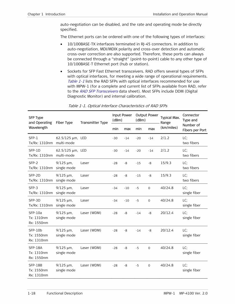
• Sockets for SFP Fast Ethernet transceivers. RAD offers several types of SFPs with optical interfaces, for meeting a wide range of operational requirements. Table 1-1 lists the RAD SFPs with optical interfaces recommended for use with MPW-1 (for a complete and current list of SFPs available from RAD, refer to the RAD SFP Transceivers data sheet). Most SFPs include DDM (Digital Diagnostic Monitor) and internal calibration.
Table 1-1. Optical Interface Characteristics of RAD SFPs
SFP Type
and Operating
Wavelength
Fiber Type Transmitter Type
Input Power
(dBm)
Output Power
(dBm) Typical Max.
Range
(km/miles)
Connector
Type and
Number of
Fibers per Portmin max min max
SFP-1
Tx/Rx: 1310nm
62.5/125 μm,
multi-mode
LED -30 -14 -20 -14 2/1.2 LC;
two fibers
SFP-1D
Tx/Rx: 1310nm
62.5/125 μm,
multi-mode
LED -30 -14 -20 -14 2/1.2 LC;
two fibers
SFP-2
Tx/Rx: 1310nm
9/125 μm,
single mode
Laser -28 -8 -15 -8 15/9.3 LC;
two fibers
SFP-2D
Tx/Rx: 1310nm
9/125 μm,
single mode
Laser -28 -8 -15 -8 15/9.3 LC;
two fibers
SFP-3
Tx/Rx: 1310nm
9/125 μm,
single mode
Laser -34 -10 -5 0 40/24.8 LC;
single fiber
SFP-3D
Tx/Rx: 1310nm
9/125 μm,
single mode
Laser -34 -10 -5 0 40/24.8 LC;
single fiber
SFP-10a
Tx: 1310nm
Rx: 1550nm
9/125 μm,
single mode
Laser (WDM) -28 -8 -14 -8 20/12.4 LC;
single fiber
SFP-10b
Tx: 1550nm
Rx: 1310nm
9/125 μm,
single mode
Laser (WDM) -28 -8 -14 -8 20/12.4 LC;
single fiber
SFP-18A
Tx: 1310nm
Rx: 1550nm
9/125 μm,
single mode
Laser (WDM) -28 -8 -5 0 40/24.8 LC;
single fiber
SFP-18B
Tx: 1550nm
Rx: 1310nm
9/125 μm,
single mode
Laser (WDM) -28 -8 -5 0 40/24.8 LC;
single fiber

Installation and Operation Manual Chapter 1 Introduction
MPW-1 MP-4100 Ver. 2.0 Functional Description 1-19
SFP Type
and Operating
Wavelength
Fiber Type Transmitter Type
Input Power
(dBm)
Output Power
(dBm) Typical Max.
Range
(km/miles)
Connector
Type and
Number of
Fibers per Portmin max min max
SFP-19A
Tx: 1490nm
Rx: 1570nm
9/125 μm,
single mode
Laser (WDM) -30 -8 0 +5 80/49.7 LC;
single fiber
SFP-19B
Tx: 1570nm
Rx: 1490nm
9/125 μm,
single mode
Laser (WDM) -30 -8 0 +5 80/49.7 LC;
two fibers
It is strongly recommended to order MPW-1 with original RAD SFPs installed. This will ensure that prior to shipping, RAD has performed comprehensive functional quality tests on the entire assembled unit, including the SFP devices. RAD cannot guarantee full compliance to product specifications for units using non-RAD SFPs.
Note that RAD also offers Fast Ethernet SFPs with copper interfaces (with RJ-45 connector); however, when copper interfaces are needed, it is more cost-effective to order MPW-1 with 10/100BASE-TX interfaces.
Ethernet Layer 2 Switch Capabilities
The MPW-1 Ethernet switching subsystem fully complies with the IEEE 802.3/Ethernet V.2 standards, and has full VLAN support. The switching subsystem has memory-based switch fabric with true non-blocking switching performance. The subsystem collects a wide range of performance monitoring parameters, which can be read by management.
The switching subsystem ports are used as follows:
• Three ports are connected via transceivers to the external (ETH 1, ETH 2, and ETH 3) ports.
• Two Fast Ethernet ports connect to the CL module:
One Fast Ethernet port is connected to the Ethernet traffic handling subsystem of the CL modules installed in the Megaplex-4100 (only CL.1/GbE and CL.1/155GbE modules include an Ethernet traffic handling section). This connection enables the MPW-1 module to accept Ethernet traffic from other modules installed in the Megaplex-4100; therefore, when Megaplex-4100 uses CL.1 or CL.1/155 modules, only Ethernet traffic from the local MPW-1 Ethernet ports can be processed by the MPW-1.
The second Fast Ethernet port is connected to the management handling section of the CL modules installed in the Megaplex-4100 (this section is available on all CL modules).
One management port, connects to the MPW-1 local management subsystem.
One port connects to the module TDM cross-connect matrix, through the Ethernet termination and processing subsystem.
Note

Chapter 1 Introduction Installation and Operation Manual
1-20 Functional Description MPW-1 MP-4100 Ver. 2.0
Each switching subsystem port is supported by an independent MAC controller that performs all the functions required by the IEEE 802.3 protocol.
The local Ethernet switching subsystem performs classification and switching functions among its ports. The Ethernet switch determines the destination of each frame in accordance with the configured Ethernet flows. The classification of each user network is based on the VLAN ID, or on the port, if no customer-side VLAN ID (C-VLAN) is configured. The switch will directly forward Ethernet traffic carrying locally-terminated pseudowires to local Ethernet ports; any other traffic will be forwarded through the MPW-1 Fast Ethernet data bus to the CL module, for processing by the CL module Ethernet traffic handling subsystem.
Ethernet Termination and Processing
The Ethernet termination and processing function provides an interface between the Ethernet switching subsystem and the local TDM cross-connect matrix: in the transmit direction, the payload received from TDM media is packetized and inserted in Ethernet frames for transmission to the appropriate Ethernet port. The reverse operation is performed for the incoming Ethernet frames.
Controlling Pseudowire Routing
The Megaplex-4100 router function is used to route pseudowire packets generated by the MPW-1 modules installed in the chassis to their destination. It also provides ARP services.
The terms and parameters needed by the Megaplex-4100 router function to support pseudowire routing are explained below:
• Router interfaces: the Megaplex-4100 router function supports up to 100 router interfaces, each assigned a unique index number. Each router interface has its own IP address; you must also specify an IP subnet mask, and the module and port on which interface is located.
For each router interface, you can also enable the use of VLAN tagging and specify a VLAN ID, to enable differentiating the traffic carried by this router. Note that when the router interface is located on a GbE port or a VCG, VLAN tagging is always enabled.
Each MPW-1 supports up to 6 different router interfaces; additional interfaces can be configured on any bridge port in the Megaplex-4100. The IP address of the appropriate interface is automatically inserted as the pseudowire source IP address.
For Megaplex-4100 equipped with CL.1 or CL.1/155 modules, you can define router interfaces only on the Ethernet ports of the same MPW-1 module.
• Pseudowire peers: the pseudowire destination is referred to as the pseudowire peer. Megaplex-4100 supports up to 100 peers, each assigned a unique index number. The index number is then used to specify the pseudowire destination, instead of directly providing the necessary destination information. To configure a peer, it is necessary to provide its IP address, and as an option – the next hop IP address.
Pay attention to the following points:
Note

Installation and Operation Manual Chapter 1 Introduction
MPW-1 MP-4100 Ver. 2.0 Functional Description 1-21
Pseudowires configured on different MPW-1 modules must be configured with different peers, even if the destination address is the same.
Different peers must not have the same destination IP address and the same next hop IP address (at least one of these parameters must be different). Therefore, if it necessary for several pseudowires to reach the same IP address, create separate router interfaces.
• Static routes: to control the paths used to reach the pseudowire destinations, the Megaplex-4100 router function supports the definition of up to 100 static routes, in addition to a default gateway. To ensure that only valid forwarding information is used, the user can configure the ARP aging time.
Within the Megaplex-4100, pseudowires are forwarded to the appropriate exit port (always a router interface) by internal E-line Ethernet flows (an E-line flow is a type of Ethernet logical connection that interconnects two bridge ports).
Megaplex-4100 supports traffic and management flows. MPW-1 bridge ports can also serve the management flow. Unless specifically mentioned otherwise, in this manual the term flow means traffic flow.
Each router interface serves as a bridge port for the pseudowires using it (in addition, each MPW-1 Ethernet port also serves as a bridge port).
Bridge ports which are router interfaces appear in automatically created Ethernet flows. Actually, defining a router interface automatically creates the Ethernet E-line flow needed to internally route the pseudowire from the MPW-1 module to the best suited router interface, considering the specified pseudowire peer.
To help you design the routing information, the following list summarizes the process used to select the router interface to be used for each pseudowire peer:
1. If the peer IP address is in the subnet of a router interface, that interface will always be used.
2. If the peer IP address is not within a router interface subnet, then the router checks if the specified peer next hop address is within the subnet of a router interface. If such a router interface is found, it is selected to serve as the pseudowire exit port.
3. If neither of the previous conditions are fulfilled, the router checks if the specified peer next hop address is specified in a static route that is within the subnet of a router interface.
4. The last priority is to use the router interface that is within the default gateway subnet.
Redundancy
The MPW-1 modules support dual-cable redundancy with parallel transmission (you can find additional details on redundancy schemes supported by Megaplex-4100 in the Megaplex-4100 Installation and Operation Manual). Since traffic is always connected through internal DS1 ports, the redundancy protection is configured on these ports.
Several redundancy protection topologies can be used, as described below.
Note

Chapter 1 Introduction Installation and Operation Manual
1-22 Functional Description MPW-1 MP-4100 Ver. 2.0
Redundancy via PSN only
Figure 1-7 shows a topology which protects TDM traffic carried over PSN against failures in MPW-1 hardware, and in the transmission paths over PSN.
Figure 1-7. MPW-1 Redundancy – Hardware and Transmission Path Protection via PSN
To illustrate the flexibility of the redundancy schemes available for the MPW-1, hardware redundancy is used only at the West side:
• At the West side, two MPW-1 are used, and the redundancy is configured on internal DS1 ports located on different MPW-1 modules
• The East side uses a single MPW-1, and therefore supports only transmission path redundancy. For this mode, redundancy is configured on internal DS1 ports located on the same MPW-1.
• To enable hardware redundancy at the East side, it is necessary to install two MPW-1 modules, same as at the West side.
When MPW-1 external Fast Ethernet ports are directly connected to the PSN, true hardware redundancy is always possible. When MPW-1 connection to the PSN is provided through bridge ports on other modules, true hardware redundancy is available only when redundancy is also enabled on the other modules. For example, when the connection is made via the GbE ports of CL.1/155GbE modules, redundancy for the CL.1/155GbE PSN interface must also be enabled.
For each redundancy pair, the user must first configure the internal DS1 port that will serve as the primary port: the configuration prepared for the primary internal DS1 port is copied to the other port of the pair. In addition, it is necessary to configure pseudowires from each internal DS1 port in the redundancy pair to the desired destinations. Make sure to enable OAM, which is essential to proper operation of the redundancy feature (see the OAM Protocol section).
The pseudowires serving the standby (offline) internal DS1 port carry only OAM packets, which require relatively little bandwidth. When a problem causes switching to standby, the traffic is switched to the standby pseudowires, and the offline pseudowires attempt to transmit OAM packets.
Redundancy switching (flipping) is always revertive: after the failure is corrected, the primary port becomes again the active port.
Upon turn-on, the first port to enter normal operation is selected as the active (online) port of the pair. Thus, if this port is not the primary port, when the primary port starts normal operation flipping occurs and the primary port is selected as the active port.
Note

Installation and Operation Manual Chapter 1 Introduction
MPW-1 MP-4100 Ver. 2.0 Functional Description 1-23
Redundancy via PSN and TDM (E1) Networks
The dual-cable, parallel transmission redundancy mode supported by Megaplex-4100 enables protecting traffic over different media. Therefore, a MPW-1 internal DS1 port can be the redundancy partner of an E1 or PDH port on another I/O, respectively CL, module. This could be used in two ways, depending on the application requirements:
• To add protection for selected E1 links when no TDM transport capacity can be assigned for redundancy, MPW-1 modules may be used to provide the protection over the PSN. For purpose, the E1 port to be protected would be configured as the primary port, and an internal DS1 port of a MPW-1 will be assigned and configured as the protection (offline) port. This ensures that unless a fault occurs, the transmission quality is that available over TDM links, and very little bandwidth is consumed on the PSN.
• When some TDM transport capacity is available, it is possible to add protection for critical traffic carried by means of MPW-1 modules over the PSN, without using the same media (PSN) for protection. In this case, MPW-1 internal DS1 ports are configured as the primary ports, and E1 ports are configured as the protection ports.
Application Guidelines
Bandwidth Utilization Considerations
When selecting parameters for a new pseudowire, one of the critical parameters is the payload size, which is determined by the number of TDM bytes per packet. This parameter affects several important performance aspects:
• Bandwidth utilization: because of the relatively short payload (especially relevant for TDMoPSN and HDLCoPSN), the bandwidth utilization efficiency depends on the overhead that must be transmitted to the network in order to support the transmission of a certain amount of payload.
The overhead depends on the packet structure: for example, for UDP/IP networks the overhead is 50 bytes when using VLANs, and 46 bytes without VLANs
The payload depends on the number of TDM bytes, and varies between 48 to 1440 bytes.
For example, when using the minimum payload size (48 bytes), bandwidth utilization efficiency is around 50%.
• Packetizing delay and the associated delay variance. Bandwidth utilization efficiency increases when using a large payload size per frame. However, there are additional aspects that must be considered when selecting the size of the packet payload:
Packetization time: the packet filling time, which is the time needed to load the payload into an Ethernet frame, increases in direct proportion to the number of bytes in the packet payload. This is particularly significant for pseudowires with few timeslots; for example, a voice channel could be carried by a single-timeslot pseudowire. Considering the nominal filling rate (approximately one byte every 0.125 msec), the time needed to fill a single-timeslot TDMoPSN pseudowire is as follows:

Chapter 1 Introduction Installation and Operation Manual
1-24 Functional Description MPW-1 MP-4100 Ver. 2.0
At 48 TDM bytes per frame: 5.5 msec when signaling is transferred, and 5.9 msec without signaling
At 384 TDM bytes per frame: 44 msec when signaling is transferred, and 47 msec without signaling
Therefore, for pseudowires with a few timeslots, it is recommended to use the minimum payload size (48 bytes).
In general, the TDMoPSN packetization delay is calculated with the following formula:
Packetization delay (ms) = TS
0.125N 47 ××
where N is the selected multiplier, 1 to 30:
N = 48
ebytes/framTDM
and TS is the number of assigned timeslots.
Therefore, before considering any other delays encountered along the end-to-end transmission path, the round-trip (or echo) delay for the voice channel example presented above is 92 msec at 384 TDM bytes per frame (including the additional intrinsic delay of module – see below).
Such long delays may also cause time-out in certain data transmission protocols.
Intrinsic jitter: the transmission of packets to the network is performed at nominally equal intervals (usually, the interval is 1 msec). This means that every 1 msec the packet processor sends to the network all the frames ready for transmission. As a result, the actual payload transmission intervals vary in an apparently random way whose peak value depends on the pseudowire size, an effect called delay variance (or jitter).
For example, a pseudowire with 6 timeslots will fill a 48-byte payload field of an Ethernet frame every 1 msec. If the sending instants are not perfectly synchronized with the filling instants, the sending time will sometimes occur just in time and sometimes will be delayed by 1 msec relative to the ideal, creating a peak delay variance of 1 msec at the transmitting side.
The intrinsic jitter in other cases is lower, therefore the delay variance generated by the MPW-1 modules will not exceed 2 msec.
• Round-trip delay. The round-trip delay for the voice path, in milliseconds, is calculated as follows:
2 × [“Packetization Delay” + “Jitter Buffer Size” + 1] + “PSN Round Trip Delay”
The actual value is within ±2 msec of the calculated value.
Sometimes, it is necessary to evaluate the transmission bandwidth required on the PSN, which also depends on the number of TDM bytes. Use the following formula:
Bandwidth (bps) = [(Frame Overhead (bytes) + TDM Bytes/Frame) × 8] × Frames/Second

Installation and Operation Manual Chapter 1 Introduction
MPW-1 MP-4100 Ver. 2.0 Functional Description 1-25
The frame overhead and the number of TDM bytes per frame have already been presented; the additional parameter is the number of frames per second, which assumes the following values:
• Unframed E1 stream: 5447/N, where N is the multiplier of 48 bytes specified when selecting the number of TDM bytes per frame
• Framed E1 stream: 8000 × k/47N, where k is the number of timeslots assigned to the pseudowire.
Determining UDP Port Numbers Used by Pseudowires
For UDP/IP networks, the pseudowire label determines the source UDP port of a pseudowire (at the other endpoint of the pseudowire, this port number must then be inserted as the destination port). The method used to assign the source UDP port is as follows (unless explicitly stated otherwise, all the numbers are in hexadecimal notation):
• For TDMoIP CE pseudowires using packet payload Version V1:
During normal operation, the source UDP port is given by:
UDP Source Port = Pseudowire Label + 1
This means that during normal operation, the UDP ports numbers are in the range of 0 to 8191 decimal.
While the pseudowire is in the local fail state, the source UDP port changes to:
UDP Source Port = Pseudowire Label + 8000
This means that in the local fail state, the UDP ports numbers are higher than 8000 hexa (32768 decimal).
• For TDMoIP CE pseudowires using packet payload Version V2:
UDP Source Port = Pseudowire Label + 2000
This means that for TDMoIP CE pseudowires, all the UDP ports numbers are higher than 2000 hexa (8192 decimal). This also applies to HDLCoPSN.
When application requirements cause the MPW-1 module to send to the same peer (destination IP address) packets using both payload version V1 and payload version V2, there is a potential for conflict. For example:
When you assign a certain label (for example, Out PW Label is set to 100) to a pseudowire using payload Version V1, the source UDP port is 101
Now, you cannot assign the next label (Out PW Label of 101 in this example) to a pseudowire using payload Version V2, because the resulting source UDP port is also 101
So, it is always necessary to must skip (never use) the pseudowire label next to the label assigned to a pseudowire using payload Version V1, if the next pseudowire uses payload Version V2.
• For CESoPSN and SAToPSN pseudowires using packet payload Version V2:
UDP Source Port = Pseudowire Number + C000
This means that all the UDP ports numbers are higher than C000 hexa (49152 decimal).

Chapter 1 Introduction Installation and Operation Manual
1-26 Functional Description MPW-1 MP-4100 Ver. 2.0
MPW-1 Timing Subsystem
The MPW-1 timing subsystem performs the following main functions:
• Generates the clock and timing signals required by the transmit paths of the module. These signals are locked to the Megaplex-4100 nodal timing.
• Can generate reference clock signals for the nodal Megaplex-4100 timing subsystem, derived from the recovered clock signals of user-selected pseudowires (see the Adaptive Timing section), in accordance with the commands received from the CL module.
MPW-1 Local Management Subsystem
The local management subsystem performs two main functions:
• Controls the operation of the various circuits located on the MPW-1 module in accordance with the commands received from the CL module through the Megaplex-4100 management channel.
• Stores the application software of the MPW-1 module. The software can be updated through the CL module.
• Controls the routing of management traffic through the MPW-1. MPW-1 supports the transfer of management traffic, inband, for both TDM and Ethernet applications:
Inband management through MPW-1 Ethernet ports and associated router interfaces, which are included in the management flow configured by the user on the Megaplex-4100.
One dedicated management timeslot can be assigned on each internal DS1 port operating in a framed mode. This enables extending the management connections, through a pseudowire that carries the management timeslot, to other RAD equipment using inband management over dedicate timeslots. Thus, remote RAD equipment with E1 and T1 interfaces connected through pseudowires to the local Megaplex-4100 can also be managed inband, using a dedicated timeslot, by the same network management system that manages the local Megaplex-4100, for example, RADview.
MPW-1 Diagnostic Functions
The MPW-1 module panel includes indicators that display the status of Ethernet interfaces (see details in Section 1.2).
The MPW-1 module includes the following diagnostic functions:
• Self-test upon power-up
• Local and remote loopbacks on selected timeslots of the internal DS1 port level that can be controlled by the operator using Megaplex-4100 system management
• Ping test, which enable checking the IP connectivity to the pseudowire destination IP address from the MPW-1 packet ports.

Installation and Operation Manual Chapter 1 Introduction
MPW-1 MP-4100 Ver. 2.0 Technical Specifications 1-27
1.4 Technical Specifications
General Function TDM pseudowire access gateway with internal ports
Internal TDM Ports 8 internal DS1 ports, with 32 timeslots per port (258 timeslots total, equivalent to 8×2.048 Mbps)
Internal Packet Ports
Two Fast Ethernet internal ports toward the packet (StarLAN) bus
External Packet Ports
Three 10/100 Mbps ports
Number of Pseudowires
• Up to 16 active pseudowires per Internal DS1 port
• Up to 128 pseudowires per MPW-1
• Up to 640 pseudowires per Megaplex-4100
Pseudowire Protocols
• TDMoIP in accordance with RFC5087
• TDMoMPLS in accordance with RFC5087 and ITU-T Rec. Y.1413
• HDLCoPSN in accordance with RFC5087 and RFC4618 (except Clause 5.3 – PPP)
• CESoPSN in accordance with RFC5086
• SAToPSN in accordance with RFC4553
Packet Switched Network Types
• UDP over IP
• MPLS over ETH
Jitter Buffer Size User-configurable per pseudowire:
• Unframed mode: 0.5 to 200 msec, with 1-μsec granularity
• Framed modes: 2.5 to 200 msec, with 1-μsec granularity
Clock Modes • Based on Megaplex-4100 nodal timing
• Independent adaptive clock recovery mechanisms per pseudowire, recovered clock can serve as Megaplex-4100 nodal timing clock source
Chapter 1 Introduction Installation and Operation Manual
1-28 Technical Specifications MPW-1 MP-4100 Ver. 2.0
Payload Routing Packet Routing • Static routing (up to 100 static routes per Megaplex-4100)
• Up to 6 router interfaces per MPW-1, and up to 100 router interfaces per Megaplex-4100 (each router interface has its own source IP address)
• Up to 100 pseudowire destinations (peers) per Megaplex-4100
Exit Ports • User-defined internal routing (any packet processor to any external Fast Ethernet port), and connection parameters (each pseudowire to any destination)
• For Megaplex-4100 with GbE ports: in accordance with user-defined flows, to any bridge port in Megaplex-4100
Ethernet Interfaces
Number of Ports Three 10/100 Mbps ports (either fiber-optic or copper, in accordance with order)
Data Rate and Mode
10 or 100 Mbps, half- or full-duplex, selected by auto-negotiation or configured by the user
Maximum Frame Size
1600 bytes
Fiber Optic Ports Hot-swappable SFPs
Note: For detailed specifications of the SFP transceivers, see Table 1-1 and RAD SFP Transceivers data sheet. RJ-45 copper interfaces also available as SFPs (model SFP-9F)
Copper Ports
Type 10/100Base-TX
Connector Shielded RJ-45
Note: RJ-45 copper interfaces are also available for MPW-1 with SFP sockets (RAD SFP model SFP-9F)
Indicators (per Ethernet port)
• ACT (yellow): flashes in accordance with the transmit and/or receive activity on the corresponding port
• LINK (green): lights when the link integrity signal is detected by the corresponding port
Diagnostics User-Controlled Port Loopbacks
• Local loopback per selected timeslots on each internal DS1 port
• Remote loopback per selected timeslots on each internal DS1 port
Configuration Programmable via Megaplex-4100 management system

MPW-1 MP-4100 Ver. 2.0 Installing the Module 2-1
Chapter 2
Installation
This Chapter provides installation and setup instructions for MPW-1 modules.
The information presented in this Chapter supplements the general Megaplex-4100 installation, configuration and operation instructions contained in the Megaplex-4100 Installation and Operation Manual.
2.1 Installing the Module
MPW-1 modules may be installed in an operating unit (hot insertion).
Before performing any internal settings, adjustment, maintenance, or repairs, first disconnect all the cables from the module, and then remove the module from the Megaplex enclosure. No internal settings, adjustment, maintenance, and repairs may be performed by either the operator or the user; such activities may be performed only by a skilled technician who is aware of the hazards involved. Always observe standard safety precautions during installation, operation, and maintenance of this product.
The MPW-1 module contains components sensitive to electrostatic discharge (ESD). To prevent ESD damage, always hold the module by its sides, and do not touch the module components or connectors.
To prevent physical damage to the electronic components assembled on the two sides of the module printed circuit boards (PCB) while it is inserted into its chassis slot, support the module while sliding it into position and make sure that its components do not touch the chassis structure, nor other modules.
Preparations for Installation
No preparations are required for MPW-1 modules with RJ-45 copper interfaces.
For MPW-1 modules equipped with SFPs, it may be necessary to install, or replace, SFPs.
MPW-1 modules have three installation positions for SFPs, designated ETH1, ETH2, and ETH3:
• To install an SFP, use the procedure given in the Installing an SFP section.
• To replace an SFP, use the procedure given in the Replacing an SFP section.
Warning
Caution
Caution

Chapter 2 Installation Installation and Operation Manual
2-2 Installing the Module MPW-1 MP-4100 Ver. 2.0
MPW-1 modules equipped with RAD-supplied SFP plug-in modules comply with laser product performance standards set by government agencies for Class 1 laser products. The modules do not emit hazardous light, and the beam is totally enclosed during all operating modes of customer operation and maintenance.
Third-party SFP optical transceivers may be also used, provided they are approved by an internationally recognized regulatory agency, and comply with the national laser safety regulations for Class 1 laser equipment. However, RAD strongly recommends ordering the MPW-1 with RAD SFPs, as this permits full performance testing of the supplied equipment.
MPW-1 modules are shipped with protective covers installed on all the optical connectors. Keep the covers for reuse, to reinstall the cover over the optical connector as soon as the optical cable is disconnected.
SFPs installed on MPW-1 modules may be equipped with a laser diode. In such cases, a label with the laser class and other warnings as applicable will be attached near the optical transmitter. The laser warning symbol may be also attached.
For your safety:
• Before turning on the equipment, make sure that the fiber optic cable is intact and is connected to the optical transmitter.
• Do not use broken or unterminated fiber-optic cables/connectors.
• Do not look straight at the laser beam, and do not look directly into the optical connectors while the module is operating.
• Do not attempt to adjust the laser drive current.
• The use of optical instruments with this product will increase eye hazard. Laser power up to 1 mW could be collected by an optical instrument.
• Use of controls or adjustment or performing procedures other than those specified herein may result in hazardous radiation exposure.
ATTENTION: The laser beam may be invisible!
Installing an SFP
When installing an optical SFP in an operating module, be aware that it may immediately start generating laser radiation.
During the installation of an SFP with optical interfaces, make sure that all the optical connectors are closed by protective caps.
Do not remove the covers until you are ready to connect optical fibers to the connectors. Be aware that when inserting an SFP into a working module, the SFP transmitter may start transmitting as soon as it is inserted.
All the following procedures are illustrated for typical SFPs with optical interfaces. Your SFPs may look different.
Warning
Caution
Note
Warning
Warning
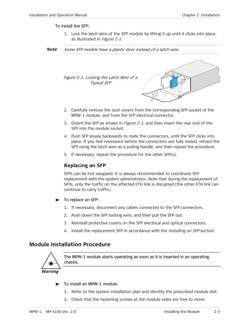
Installation and Operation Manual Chapter 2 Installation
MPW-1 MP-4100 Ver. 2.0 Installing the Module 2-3
To install the SFP:
1. Lock the latch wire of the SFP module by lifting it up until it clicks into place, as illustrated in Figure 2-1.
Some SFP models have a plastic door instead of a latch wire.
Figure 2-1. Locking the Latch Wire of a Typical SFP
2. Carefully remove the dust covers from the corresponding SFP socket of the MPW-1 module, and from the SFP electrical connector.
3. Orient the SFP as shown in Figure 2-1, and then insert the rear end of the SFP into the module socket.
4. Push SFP slowly backwards to mate the connectors, until the SFP clicks into place. If you feel resistance before the connectors are fully mated, retract the SFP using the latch wire as a pulling handle, and then repeat the procedure.
5. If necessary, repeat the procedure for the other SFP(s).
Replacing an SFP
SFPs can be hot-swapped. It is always recommended to coordinate SFP replacement with the system administrator. Note that during the replacement of SFPs, only the traffic on the affected ETH link is disrupted (the other ETH link can continue to carry traffic).
To replace an SFP:
1. If necessary, disconnect any cables connected to the SFP connectors.
2. Push down the SFP locking wire, and then pull the SFP out.
3. Reinstall protective covers on the SFP electrical and optical connectors.
4. Install the replacement SFP in accordance with the Installing an SFP section.
Module Installation Procedure
The MPW-1 module starts operating as soon as it is inserted in an operating chassis.
To install an MPW-1 module:
1. Refer to the system installation plan and identify the prescribed module slot.
2. Check that the fastening screws at the module sides are free to move.
Note
Warning
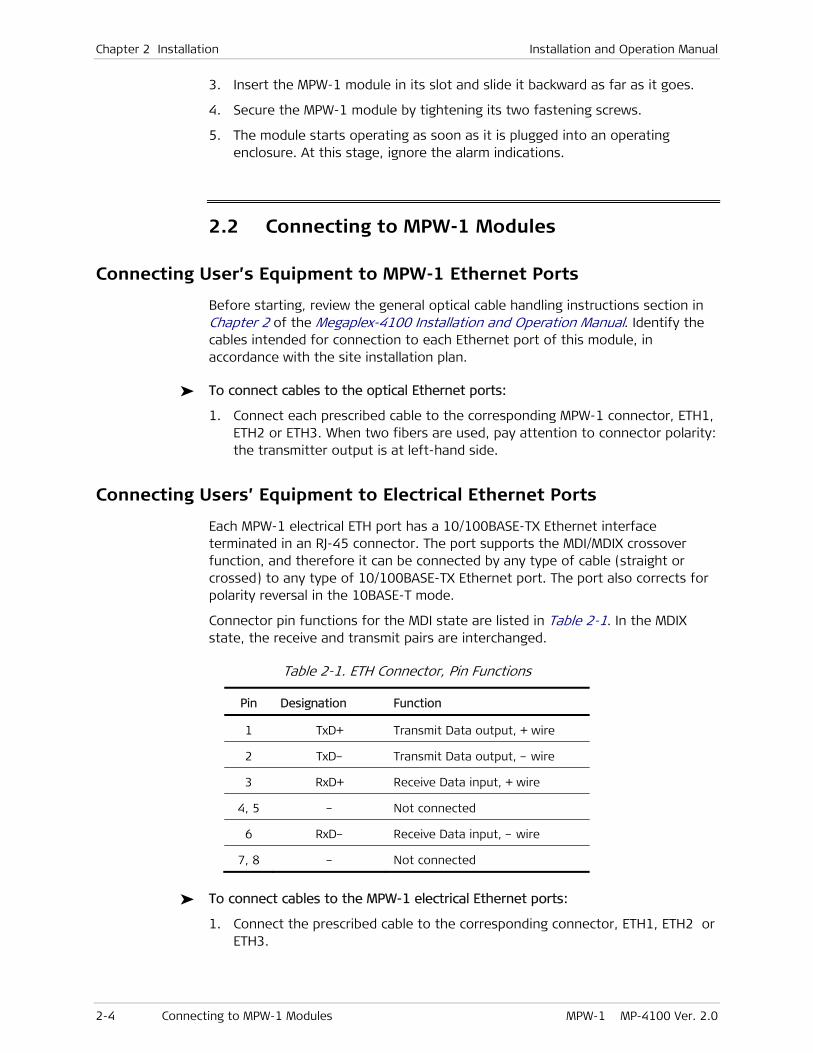
Chapter 2 Installation Installation and Operation Manual
2-4 Connecting to MPW-1 Modules MPW-1 MP-4100 Ver. 2.0
3. Insert the MPW-1 module in its slot and slide it backward as far as it goes.
4. Secure the MPW-1 module by tightening its two fastening screws.
5. The module starts operating as soon as it is plugged into an operating enclosure. At this stage, ignore the alarm indications.
2.2 Connecting to MPW-1 Modules
Connecting User’s Equipment to MPW-1 Ethernet Ports
Before starting, review the general optical cable handling instructions section in Chapter 2 of the Megaplex-4100 Installation and Operation Manual. Identify the cables intended for connection to each Ethernet port of this module, in accordance with the site installation plan.
To connect cables to the optical Ethernet ports:
1. Connect each prescribed cable to the corresponding MPW-1 connector, ETH1, ETH2 or ETH3. When two fibers are used, pay attention to connector polarity: the transmitter output is at left-hand side.
Connecting Users’ Equipment to Electrical Ethernet Ports
Each MPW-1 electrical ETH port has a 10/100BASE-TX Ethernet interface terminated in an RJ-45 connector. The port supports the MDI/MDIX crossover function, and therefore it can be connected by any type of cable (straight or crossed) to any type of 10/100BASE-TX Ethernet port. The port also corrects for polarity reversal in the 10BASE-T mode.
Connector pin functions for the MDI state are listed in Table 2-1. In the MDIX state, the receive and transmit pairs are interchanged.
Table 2-1. ETH Connector, Pin Functions
Pin Designation Function
1 TxD+ Transmit Data output, + wire
2 TxD– Transmit Data output, – wire
3 RxD+ Receive Data input, + wire
4, 5 – Not connected
6 RxD– Receive Data input, – wire
7, 8 – Not connected
To connect cables to the MPW-1 electrical Ethernet ports:
1. Connect the prescribed cable to the corresponding connector, ETH1, ETH2 or ETH3.
MPW-1 MP-4100 Ver. 2.0 Normal Indications 3-1
Chapter 3
Configuration
This Chapter provides specific configuration information for MPW-1 modules.
The configuration activities are performed by means of the management system used to control the Megaplex-4100 unit.
For general instructions, additional configuration procedures, and background information, refer to the Megaplex-4100 Installation and Operation Manual.
• MPW-1 modules provide pseudowire services to the other modules installed in the Megaplex-4100. Therefore, before configuring MPW-1 modules it is recommended to configure the other Megaplex-4100 modules and services. In particular, make sure to configure Ethernet services.
• Make sure to plan ahead the configuration sequence, because Megaplex-4100 databases can be updated only after correctly completing the configuration activities: any sanity error will prevent saving the changes to the database being modified. For example, a common cause of sanity errors that may prevent updating the database is that timeslots have to be assigned to ports of other modules that will be served by the MPW-1 ports.
MPW-1 configuration includes the following types of tasks:
• Tasks needed to configure an MPW-1 module and put it into service. These tasks include enabling the desired module physical ports, configuring their parameters, and configuring the utilization of the module TDM (internal DS1) ports.
• Tasks related to the provisioning of pseudowire services.
• When necessary, modify the system timing reference to use selected pseudowire connections for the Megaplex-4100.
The recommended configuration sequence for each type of task is described below, together with references to the supervision terminal screens used to perform each task.
To configure an MPW-1 module and put it into service (see Section 3.3):
1. If necessary, program (add) an MPW-1 module not yet installed in the Megaplex-4100 chassis to the database.
For the supervision terminal, use Configuration > System > Card Type.
2. Configure the physical layer parameters for the active internal DS1 and Ethernet ports of the MPW-1 module.
For the supervision terminal, use Configuration > Physical Layer > I/O.
3. Configure the utilization of the module TDM ports:
Notes

Chapter 3 Configuration Installation and Operation Manual
3-2 Normal Indications MPW-1 MP-4100 Ver. 2.0
1. For framed internal DS1 ports using the DS0 cross-connect mode: configure the utilization of the individual timeslots, including timeslots using split assignment, for each module port. You can assign timeslots only to ports already configured with Administrative Status set to Up.
For MPW-1 internal DS1 ports using the DS1 cross-connect mode, the connection to another port is configured as part of the port physical layer parameters.
For the supervision terminal, use Configuration > Physical Layer > I/O > TS Assignment, or Configuration > System > TS Assignment.
2. For internal DS1 ports that connect to PDH ports on a CL module with STM-1 or OC-3 links (CL.1/155 or CL.1/155GbE): configure the corresponding PDH port with compatible parameters (in particular, configure a compatible framing mode), and then map the PDH port to the prescribed TU of the specified SDH port.
For the supervision terminal, use Configuration > Logical Ports > CL, and Configuration > System > Mapping, respectively (for instructions, refer to the Megaplex-4100 Installation and Operation Manual).
To configure pseudowire services on the module (see Section 3.4):
1. Configure MPW-1 router parameters (interfaces, associated static routes, default gateway, and ARP aging time).
For the supervision terminal, use Configuration > Applications > Router.
2. Configure the pseudowire peers (destinations).
For the supervision terminal, use Configuration > Applications > Multi-Service over PSN > Peers.
3. Configure the pseudowires terminated at the MPW-1 internal DS1 ports.
For the supervision terminal, use Configuration > Applications > Multi-Service over PSN > PW.
4. If necessary, configure fault propagation for the relevant MPW-1 pseudowires.
For the supervision terminal, use Configuration > System > Fault Propagation (for additional instructions, refer to the Megaplex-4100 Installation and Operation Manual).
To configure pseudowires as system timing reference (see Section 3.5):
1. When necessary, modify the system timing reference to use the recovered clock of an MPW-1 pseudowire as timing reference.
For the supervision terminal, use Configuration > System > Clock Source (for additional information, see also the Megaplex-4100 Installation and Operation Manual).
Note

Installation and Operation Manual Chapter 3 Configuration
MPW-1 MP-4100 Ver. 2.0 Default Settings 3-3
3.1 Normal Indications
The status of each MPW-1 Ethernet port is indicated by a separate set of indicators. After the equipment connected to the module Ethernet ports is operational, the following indications should appear for each active port:
• The LINK indicator lights as long as the port is connected to operational equipment
• The ACT indicator may light continuously, or flash from time to time, in accordance with the transmit and receive activity at the corresponding port.
3.2 Default Settings
Table 3-1 lists the MPW-1 factory-default parameters.
Table 3-1. MPW-1 Factory-Default Parameters
Parameter Description Factory Default Value
Internal DS1 Port – Physical Layer Configuration Parameters
Administrative Status Port administrative status Down
Name Port logical name Empty string
Redundancy Port redundancy mode None
Primary Port function in redundancy pair (relevant when
redundancy is enabled)
None
Redundant Slot Redundancy pair slot (relevant when redundancy is
enabled)
CL
Redundant Port Redundancy pair port (relevant when redundancy is
enabled)
– (no port selected)
Wait to Restore Time, in seconds, following the last redundancy time
switching (flipping) during which alarms are ignored
300
Cross Connect Handling of the data passing through the selected port Framed mode: DS0
Unframed mode: DS1
Destination Slot I/O slot to which data stream is routed (when using DS1
cross-connect mode)
CL
Destination Port Port to which data stream is routed (when using DS1
cross-connect mode)
– (no port selected)
Framing Handling mode of payload flowing through the selected
internal DS1 port
Framed
Signaling Support for signaling information (relevant when using a
framed mode)
No
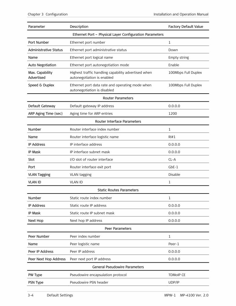
Chapter 3 Configuration Installation and Operation Manual
3-4 Default Settings MPW-1 MP-4100 Ver. 2.0
Parameter Description Factory Default Value
Ethernet Port – Physical Layer Configuration Parameters
Port Number Ethernet port number 1
Administrative Status Ethernet port administrative status Down
Name Ethernet port logical name Empty string
Auto Negotiation Ethernet port autonegotiation mode Enable
Max. Capability
Advertised
Highest traffic handling capability advertised when
autonegotiation is enabled
100Mbps Full Duplex
Speed & Duplex Ethernet port data rate and operating mode when
autonegotiation is disabled
100Mbps Full Duplex
Router Parameters
Default Gateway Default gateway IP address 0.0.0.0
ARP Aging Time (sec) Aging time for ARP entries 1200
Router Interface Parameters
Number Router interface index number 1
Name Router interface logistic name RI#1
IP Address IP interface address 0.0.0.0
IP Mask IP interface subnet mask 0.0.0.0
Slot I/O slot of router interface CL-A
Port Router interface exit port GbE-1
VLAN Tagging VLAN tagging Disable
VLAN ID VLAN ID 1
Static Routes Parameters
Number Static route index number 1
IP Address Static route IP address 0.0.0.0
IP Mask Static route IP subnet mask 0.0.0.0
Next Hop Next hop IP address 0.0.0.0
Peer Parameters
Peer Number Peer index number 1
Name Peer logistic name Peer-1
Peer IP Address Peer IP address 0.0.0.0
Peer Next Hop Address Peer next port IP address 0.0.0.0
General Pseudowire Parameters
PW Type Pseudowire encapsulation protocol TDMoIP CE
PSN Type Pseudowire PSN header UDP/IP

Installation and Operation Manual Chapter 3 Configuration
MPW-1 MP-4100 Ver. 2.0 Default Settings 3-5
Parameter Description Factory Default Value
Peer Number Pseudowire destination index number 1
OAM Mode Pseudowire OAM support Proprietary
Out PW Label UDP/IP: UDP source port number.
MPLS/ETH: outer (tunnel) MPLS label
1
16
In PW Label UDP/IP: UDP destination port number.
MPLS/ETH: inbound MPLS label
1
16
Pseudowire PSN Parameters
ToS Layer 3 priority assigned to the traffic generated by this
pseudowire (relevant only for UDP/IP PSN)
0
Ingress Tunnel Tagging Use of an interworking MPLS label for the receive
(inbound) direction of the pseudowire (relevant only for
MPLS/ETH PSN)
Disable
Ingress Tunnel Label Inbound MPLS label used for the pseudowire (relevant only
for MPLS/ETH PSN)
16
Egress Tunnel Tagging Use of an interworking MPLS label for the transmit
(outbound) direction of the pseudowire (relevant only for
MPLS/ETH PSN)
Disable
Egress Tunnel Label Outbound MPLS label used for the pseudowire (relevant
only for MPLS/ETH PSN)
16
EXP Bits Value of the outbound EXP bits in the pseudowire MPLS
pseudowire header, used to indicate the requested Quality
of Service (relevant only for MPLS/ETH PSN)
0
VLAN Priority Layer 2 priority assigned to the pseudowire traffic when
VLAN Tagging is enabled
0
Payload Format Packet payload format V2
Pseudowire Service Parameters
TDM Bytes in Frame Number of TDM payload bytes (TDM frames for CESoPSN)
inserted in each packet (packet size)
TDMoIP: 1 × 48
CESoPSN: 4
Payload Size TDM payload size 4 to 1440
Jitter Buffer Value of the jitter buffer to be used on this pseudowire 2500
Far End Type Framing used by the equipment at the destination
endpoint
E1
Delay Sensitivity Optimum mode of the clock recovery mechanism Data
Voice OOS Code transmitted during out-of-service periods on
timeslots defined as voice timeslots
00
Data OOS Code transmitted by the port during out-of-service periods
on timeslots defined as data timeslots
00

Chapter 3 Configuration Installation and Operation Manual
3-6 Default Settings MPW-1 MP-4100 Ver. 2.0
Parameter Description Factory Default Value
OOS Signaling State of signaling bits sent to the internal DS1 port
connected to the selected pseudowire during
out-of-service periods
Forced idle
Attachment Circuit Parameters
Slot I/O slot number IO-1
Int-DS1 Number Internal DS1 port of the selected MPW-1 1
Time Slots Pseudowire timeslot assignment – (no timeslot assigned)
Recovered Clock Source Parameters
ID Recovered clock source index number 1
PW Number Pseudowire index number that will be the source with the
selected index number
The first index number
of an existing
pseudowire
Administrative Status Recovered clock source active or not Down
Source Quality Quality of original timing source Stratum 4
Network Type Type of packet switched network used to transport the
pseudowire
Type B
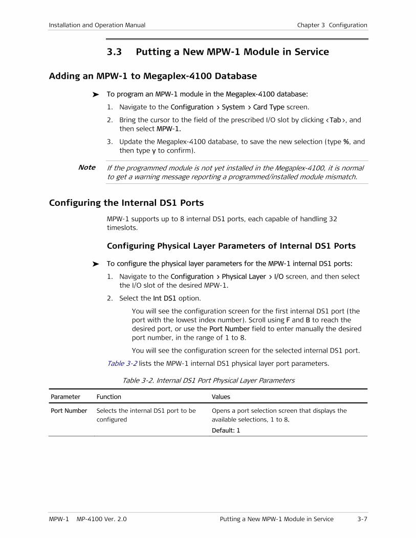
Installation and Operation Manual Chapter 3 Configuration
MPW-1 MP-4100 Ver. 2.0 Putting a New MPW-1 Module in Service 3-7
3.3 Putting a New MPW-1 Module in Service
Adding an MPW-1 to Megaplex-4100 Database
To program an MPW-1 module in the Megaplex-4100 database:
1. Navigate to the Configuration > System > Card Type screen.
2. Bring the cursor to the field of the prescribed I/O slot by clicking <Tab>, and then select MPW-1.
3. Update the Megaplex-4100 database, to save the new selection (type %, and then type y to confirm).
If the programmed module is not yet installed in the Megaplex-4100, it is normal to get a warning message reporting a programmed/installed module mismatch.
Configuring the Internal DS1 Ports
MPW-1 supports up to 8 internal DS1 ports, each capable of handling 32 timeslots.
Configuring Physical Layer Parameters of Internal DS1 Ports
To configure the physical layer parameters for the MPW-1 internal DS1 ports:
1. Navigate to the Configuration > Physical Layer > I/O screen, and then select the I/O slot of the desired MPW-1.
2. Select the Int DS1 option.
You will see the configuration screen for the first internal DS1 port (the port with the lowest index number). Scroll using F and B to reach the desired port, or use the Port Number field to enter manually the desired port number, in the range of 1 to 8.
You will see the configuration screen for the selected internal DS1 port.
Table 3-2 lists the MPW-1 internal DS1 physical layer port parameters.
Table 3-2. Internal DS1 Port Physical Layer Parameters
Parameter Function Values
Port Number Selects the internal DS1 port to be
configured
Opens a port selection screen that displays the
available selections, 1 to 8.
Default: 1
Note
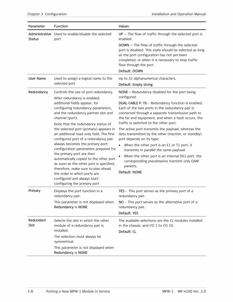
Chapter 3 Configuration Installation and Operation Manual
3-8 Putting a New MPW-1 Module in Service MPW-1 MP-4100 Ver. 2.0
Parameter Function Values
Administrative
Status
Used to enable/disable the selected
port
UP — The flow of traffic through the selected port is
enabled.
DOWN — The flow of traffic through the selected
port is disabled. This state should be selected as long
as the port configuration has not yet been
completed, or when it is necessary to stop traffic
flow through the port.
Default: DOWN
User Name Used to assign a logical name to the
selected port
Up to 32 alphanumerical characters.
Default: Empty string
Redundancy Controls the use of port redundancy.
After redundancy is enabled,
additional fields appear, for
configuring redundancy parameters,
and the redundancy partner slot and
channel (port).
Note that the redundancy status of
the selected port (primary) appears in
an additional read-only field. The first
configured port of a redundancy pair
always becomes the primary port:
configuration parameters prepared for
the primary port are then
automatically copied to the other port
as soon as the other port is specified,
therefore, make sure to plan ahead
the order in which ports are
configured and always start
configuring the primary port
NONE – Redundancy disabled for the port being
configured.
DUAL CABLE P. TX – Redundancy function is enabled.
Each of the two ports in the redundancy pair is
connected through a separate transmission path to
the far end equipment, and when a fault occurs, the
traffic is switched to the other port.
The active port transmits the payload, whereas the
data transmitted by the other (inactive, or standby)
port depends on its type:
• When the other port is an E1 or T1 port, it
transmits in parallel the same payload.
• When the other port is an internal DS1 port, the
corresponding pseudowires transmit only OAM
packets.
Default: NONE
Primary Displays the port function in a
redundancy pair.
This parameter is not displayed when
Redundancy is NONE
YES – This port serves as the primary port of a
redundancy pair.
NO – This port serves as the alternative port of a
redundancy pair.
Default: YES
Redundant
Slot Selects the slot in which the other
module of a redundancy pair is
installed.
The selection must always be
symmetrical.
This parameter is not displayed when
Redundancy is NONE
The available selections are the CL modules installed
in the chassis, and I/O 1 to I/O 10.
Default: CL

Installation and Operation Manual Chapter 3 Configuration
MPW-1 MP-4100 Ver. 2.0 Putting a New MPW-1 Module in Service 3-9
Parameter Function Values
Redundant
Port Selects the other port of a redundancy
pair.
The selection must always be
symmetrical.
This parameter is not displayed when
Redundancy is NONE
The available selections depend on the destination
module and the number of active ports on the other
module:
• 1 to 8 for external and internal E1 or T1 ports
• 1 to 8 for internal_DS1 ports
• 1 to 63 PDH ports on a CL module using STM-1
links.
• 1 to 84 for PDH ports on a CL module using OC-3
links.
Default: – (no port selected)
Wait to
Restore
Specifies the time following the last
redundancy switching (flipping) during
which alarms are ignored.
Therefore, the module starts
evaluating the criteria for redundancy
switching (flipping) only after this
interval expires. This ensures that
another flipping cannot occur before
the specified interval expires
The supported range is 0 to 999 seconds.
Default: 300
Cross Connect Selects the handling of the data
passing through the selected port
DS0 – Enables routing each individual timeslot from
this port to other module ports or pseudowires. This
mode is not supported when using the UNFRAMED
mode.
DS1 – In the UNFRAMED mode, the data stream
handled by this port is transparently connected to
another port or pseudowire.
In the FRAMED mode, only the payload timeslots are
transparently connected.
Default: DS0 for FRAMED mode.
DS1 for UNFRAMED mode
Destination
Slot
Specifies the module (I/O slot) to
which the data stream handled by the
selected port is routed.
This parameter is displayed only when
using the DS1 cross-connect mode
The available selections are the CL modules installed
in the chassis, and I/O modules IO-1 to IO-10.
Default: CL
Destination
Port
Specifies the port to which the data
stream handled by the selected port is
routed.
This parameter is displayed only when
using the DS1 cross-connect mode
The available selections depend on the destination
module and the number of active ports on the other
module:
• 1 to 8 for external and internal E1 or T1 ports
• 1 to 8 for internal_DS1 ports
• 1 to 63 PDH ports on a CL module using STM-1
links.
• 1 to 84 for PDH ports on a CL module using OC-3
links.
Default: – (no port selected)

Chapter 3 Configuration Installation and Operation Manual
3-10 Putting a New MPW-1 Module in Service MPW-1 MP-4100 Ver. 2.0
Parameter Function Values
Framing Selects the handling of the payload
flowing through the selected internal
DS1 port
FRAMED – Enables separate handling of each
individual timeslot. In this mode, it is also possible to
connect to either E1 ports or T1 ports (for T1 ports,
the maximum is 24 timeslots).
UNFRAMED – The port is considered as a whole (all
its timeslots are handled as a single group).
Default: FRAMED
Signaling Specifies whether the selected internal
DS1 port carries signaling information
(for example, channel-associated
signaling).
This parameter is displayed only when
using the FRAMED mode
YES – Port carries signaling information. Use this
selection when port timeslots will be defined as
VOICE timeslots.
NO – No signaling information.
Default: NO
TS Assignment Displays the timeslot assignment
submenu for this port
For instructions, refer to the Configuring Internal DS1 Port Timeslot Utilization section starting on page 3-11
Redundancy Configuration Guidelines
The MPW-1 modules support redundancy for protecting the traffic flowing through each of its internal DS1 ports. The redundancy mode is always revertive, that is, the traffic is automatically switched back to the primary port as soon as it returns to normal operation (except for a delay selected by means of Wait to Restore).
The redundancy partner ports can be located either on the same module, or on another module, in which case it is also possible to use internal (logical) ports of other I/O or CL modules.
When using the redundancy feature, it is necessary to select the same values for the following parameters of the two ports configured as a redundancy pair:
• Framing
• Signaling
• Voice OOS
• Data OOS
• Restoration Time
• Cross-Connect
However, you can select different Wait to Restore times, because the times selected at the two ends should be different.
To save duplication of configuration parameters, all the parameters listed above are selectable only for the primary port. The parameters of the other (alternative) port are automatically copied from the primary port after the configuration of the primary port has been completed and the database has been updated.
The same is true with respect to timeslot assignment: only one port (either the primary or the secondary) must be configured, and the timeslot assignment is automatically copied to the other port.
Note that you can see the automatically changed parameters of the other port as soon as a redundancy partner is specified during the configuration of the primary

Installation and Operation Manual Chapter 3 Configuration
MPW-1 MP-4100 Ver. 2.0 Putting a New MPW-1 Module in Service 3-11
port, but the parameters are actually changed only when the database is updated.
To avoid redundancy configuration errors, use the following procedure:
1. Before starting the configuration of the redundancy parameters, decide which port of the planned redundancy pair is to serve as the primary port, and make sure that the other port does not carry traffic.
You must always start configuring the primary port, and only after this port is fully configured, continue to the redundancy partner of the primary port.
2. Fully configure the port that is to serve as the primary port. After parameters are configured, the redundancy slot, channel (port) and primary status indicator become read-only fields.
In parallel, the parameters of the alternative port are also configured to compatible values.
3. After ending the configuration of the primary port, configure the alternative port. When you open the alternative port configuration screen, you will see read-only fields which display all the preconfigured parameters, and then the list of parameters that can be configured.
4. To change the redundancy assignments, first select None for the Redundancy parameter. This will enable you to reconfigure the system as required.
Configuring Internal DS1 Port Timeslot Utilization
The internal DS1 port provides a connection point between TDM traffic arriving from other modules and the pseudowires supported by MPW-1. Each pseudowire can be connected to only one internal DS1 port.
When an MPW-1 internal DS1 port uses the DS0 cross-connect mode (available when the port uses the Framed mode), it is necessary to connect individual timeslots to the prescribed ports on the other I/O and CL modules, in accordance with the application requirements (this action is referred to as timeslot assignment). To continue the connection over the pseudowire, when you configure the pseudowire you also specify the internal DS1 port timeslots to be collected and processed by it. You can assign timeslots only to internal DS1 ports that have been already configured, and that have their Administrative Status set to Up.
For the supervision terminal, use the last item, Time Slot Assignment, on the Configuration > Physical Layer > I/O screen of the desired MPW-1 internal DS1 port, or use the Configuration > System > TS Assignment screen in accordance with the Megaplex-4100 Installation and Operation Manual.
The connection of timeslots from the internal DS1 port to each local pseudowire is made using the Time Slots item on the Configuration > Applications > Multi-Service over PSN > PW > Service Parameters > Attachment Circuit screen.
Timeslots can be assigned for the following purposes:
• For connection to any other port of an I/O or CL module that uses the DS0 cross-connect mode (for example, framed E1 or T1 ports), or an I/O channel
Note
Note
Chapter 3 Configuration Installation and Operation Manual
3-12 Putting a New MPW-1 Module in Service MPW-1 MP-4100 Ver. 2.0
that supports connection of individual timeslots (for example, a high-speed data module).
For PDH ports, make sure to map the PDH port to the prescribed TU of the CL STM-1 or OC-3 port (for the supervision terminal, use Configuration > System > Mapping, using the instructions appearing in the Megaplex-4100 Installation and Operation Manual).
• For transferring inband management (relevant only for connections to other E1 or T1 ports). Only one management timeslot can be assigned per port
The available timeslot types are the same timeslots described for the Configuration > System > TS Assignment screen in the Megaplex-4100 Installation and Operation Manual.
Note that a timeslot assignment for a connection between two ports is accepted as valid only when it is symmetrical, that is, a suitable timeslot of the destination is also connected to the source port timeslot.
When using redundancy, timeslot assignment can be performed on either the primary or the secondary port, and the timeslot assignment is automatically copied to the redundancy partner of the primary port.
Configuring Internal DS1 Port Connections
An MPW-1 port using the DS1 cross-connect mode can only be connected to another port that uses the DS1 cross-connect mode and the same framing mode (Framed or Unframed).
Note that for ports using the DS1 cross-connect mode, the internal DS1 port bandwidth cannot be split among multiple pseudowires, and therefore the whole port bandwidth must be assigned to only one pseudowire. Although the internal DS1 port bandwidth is equivalent to 32 timeslots, the pseudowire bandwidth depends on the number of timeslots available at the other port:
• For E1 ports: 32 timeslots when using the Unframed mode, or 31 timeslots when using a Framed mode
• For T1 ports: 24 timeslots (possible only in the Framed mode)
The other port is specified as part of the port physical layer parameters. The following selections are supported:
• An external or internal port of another I/O module using the same framing mode
• A PDH port on a CL.1/155 or CL.1/155GbE module (relevant only for the Framed mode). The corresponding PDH must then be mapped to the prescribed TU of an STM-1 or OC-3 port. For the supervision terminal, use Configuration > Logical Ports > CL, and Configuration > System > Mapping, respectively (for instructions, refer to the Megaplex-4100 Installation and Operation Manual).
Configuring Physical Layer Parameters of Ethernet Ports
To configure the physical layer parameters for the MPW-1 Ethernet ports:
1. Navigate to the Configuration > Physical Layer > I/O screen, and then select the I/O slot of the desired MPW-1.

Installation and Operation Manual Chapter 3 Configuration
MPW-1 MP-4100 Ver. 2.0 Putting a New MPW-1 Module in Service 3-13
2. Select the Ethernet ports configuration option, and then select a specific port.
Alternatively, first preconfigure all the ports with the same basic parameters (All Ports option), and then sequentially select each port and change its parameters as required.
Table 3-3 describes the Ethernet port configuration parameters.
Table 3-3. Ethernet Port Physical Layer Configuration Parameters
Parameter Function Values
Port Number The Ethernet port number The available selections are 1 to 3, or All Ports.
Default: 1
Administrative
Status
Used to enable/disable the flow of
traffic through the selected Ethernet
port
DOWN – The flow of traffic is disabled. This
state should be selected as long as the
configuration of the corresponding port has not
yet been completed, or when it is necessary to
stop traffic flow through the port.
UP – The flow of traffic is enabled.
Default: DOWN
User Name Used to enter a logical name for the
selected Ethernet port
Up to 32 alphanumeric characters.
Default: Empty string
Auto Negotiation Controls the use of auto-negotiation for
the selected Ethernet port.
Auto-negotiation is used to select
automatically the mode providing the
highest possible traffic handling
capability
ENABLE – Auto-negotiation is enabled. This is
the normal operation mode.
DISABLE – Auto-negotiation is disabled. This
mode should be used only when the equipment
connected to the port does not support
auto-negotiation.
Default: ENABLE
Max. Capability
Advertised
When Auto Negotiation is ENABLE,
selects the highest traffic handling
capability to be advertised during the
auto-negotiation process. The operating
mode selected as a result of auto-
negotiation cannot exceed the
advertised capability.
When Auto Negotiation is DISABLE, this
parameter is replaced by Speed &
Duplex
The available selections are listed in ascending
order of capabilities:
10Mbps half duplex – Half-duplex operation at
10 Mbps.
10Mbps full duplex – Full-duplex operation at
10 Mbps.
100Mbps half duplex – Half-duplex operation at
100 Mbps.
100Mbps full duplex – Full-duplex operation at
100 Mbps.
Default: 100Mbps full duplex
Speed & Duplex When Auto Negotiation is DISABLE,
selects the data rate and the operating
mode of the selected Ethernet port.
When Auto Negotiation is ENABLE, this
parameter is replaced by Max. Capability
Advertised
Same selections as for the Max. Capability
Advertised parameter.
Default: 100Mbps full duplex

Chapter 3 Configuration Installation and Operation Manual
3-14 Configuring Pseudowire Services MPW-1 MP-4100 Ver. 2.0
3.4 Configuring Pseudowire Services
The pseudowire services enable converting TDM payload to packets and transferring these packets through router interfaces defined in the Megaplex-4100.
The pseudowire services supported by MPW-1 modules are configured by providing two main groups of parameters:
• Routing parameters for the Megaplex-4100 router function
• Pseudowire processing parameters
Defining a router interface creates automatically an Ethernet E-line flow, a type of Ethernet logical connection that interconnects two compatible network interfaces (called bridge ports on supervision terminal screens). Refer to Section 3.6 for a description of Ethernet flows supporting pseudowires.
Configuring the Router Function to Support Pseudowire Services
With respect to MPW-1 modules, the Megaplex-4100 router function is used to route pseudowire packets to their destination (peer). It also provides ARP services.
Each MPW-1 supports up to 6 different router interfaces (additional interfaces can be configured on any bridge port in the Megaplex-4100 – see description of Ethernet services in the Megaplex-4100 Installation and Operation Manual). The IP address of the appropriate interface is automatically inserted as the pseudowire source IP address (the destination IP address is that of the pseudowire peer, as explained in the Configuring the Pseudowire Peers section).
For Megaplex-4100 equipped with CL.1 or CL.1/155 modules, you can define router interfaces only on the Ethernet ports of the same MPW-1 module (only CL modules with GbE interfaces, that is, CL.1/155 or CL.1/155GbE, enable transferring Ethernet traffic between different I/O modules).
To control the paths used to reach the pseudowire destinations, the MPW-1 router supports the definition of up to 100 static routes, in addition to a default gateway. To ensure that only valid forwarding information is used, the user can configure the ARP aging time.
To help you design the routing information, Figure 3-1 summarizes the process used to select the router interface for each pseudowire peer. The priority of the various router interfaces, as determined by the routing process, is as follows:
1. If the peer IP address is in the subnet of a router interface, that interface will always be used.
2. If the peer IP address is not within a router interface subnet, then the router checks if the specified peer next hop address is within the subnet of a router interface.
3. If neither of the previous conditions are fulfilled, the router checks if the specified peer next hop address is specified in a static route that is within the subnet of a router interface.
Note
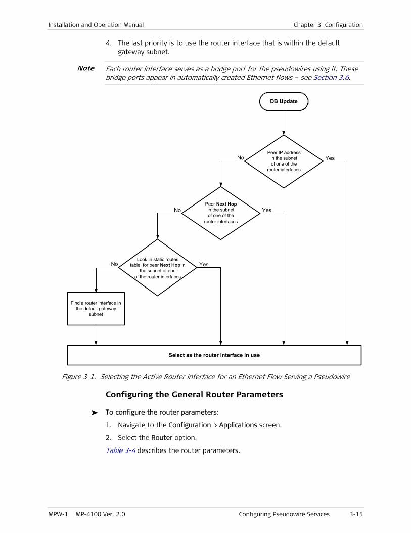
Installation and Operation Manual Chapter 3 Configuration
MPW-1 MP-4100 Ver. 2.0 Configuring Pseudowire Services 3-15
4. The last priority is to use the router interface that is within the default gateway subnet.
Each router interface serves as a bridge port for the pseudowires using it. These bridge ports appear in automatically created Ethernet flows – see Section 3.6.
DB Update
Peer IP addressin the subnetof one of the
router interfaces
No Yes
Peer Next Hopin the subnetof one of the
router interfaces
No
Look in static routestable, for peer Next Hop in
the subnet of oneof the router interfaces
Find a router interface inthe default gateway
subnet
Select as the router interface in use
Yes
YesNo
Figure 3-1. Selecting the Active Router Interface for an Ethernet Flow Serving a Pseudowire
Configuring the General Router Parameters
To configure the router parameters:
1. Navigate to the Configuration > Applications screen.
2. Select the Router option.
Table 3-4 describes the router parameters.
Note

Chapter 3 Configuration Installation and Operation Manual
3-16 Configuring Pseudowire Services MPW-1 MP-4100 Ver. 2.0
Table 3-4. Router Parameters
Parameter Function Values
Interface Displays the router interface
configuration screen
See Table 3-5 below
Static Route Displays the static route
configuration screen
See Table 3-6 below
Default Gateway Specifies the default gateway IP
address (usually an IP router port) to
which the router will send packets
when other routing criteria are not
met (see Figure 3-1).
The default value, 0.0.0.0, means
that no default gateway is defined
Type the desired IP address, using the
dotted-quad format.
Make sure that the IP address is within the
subnet of one of the router interfaces.
Default: 0.0.0.0
ARP Aging Time
(sec)
Selects the aging time for ARP
entries.
If the ARP entry for a given
destination is not refreshed before
the specified interval expires, that
information is deleted from the ARP
table
The allowed range is 300 to 1000000 sec, in
16-sec increments.
If the entered value is not a multiple of 16, the
nearest multiple of 16 not exceeding your entry,
is actually used.
Default: 1200 (20 minutes)
Configuring Router Interfaces
You can configure a total of 100 router interfaces within the Megaplex-4100, but not more than 6 interfaces per MPW-1 module.
To configure router interfaces:
1. Navigate to the Configuration > Applications > Router screen, and then select Interface.
2. Select the desired interface index:
To modify an existing interface, enter its number in the Number field, or scroll using F and B
To define a new interface, select Add. The new interface is automatically assigned the next free number, in the range of 1 to 100.
3. To delete unnecessary interfaces, select Delete (you will be requested to confirm).
Table 3-5 describes the router interface parameters.
Table 3-5. Router Interface Parameters
Parameter Function Values
Number Specifies the index number
representing the router interface
The allowed range is 1 to 100.
Default: 1
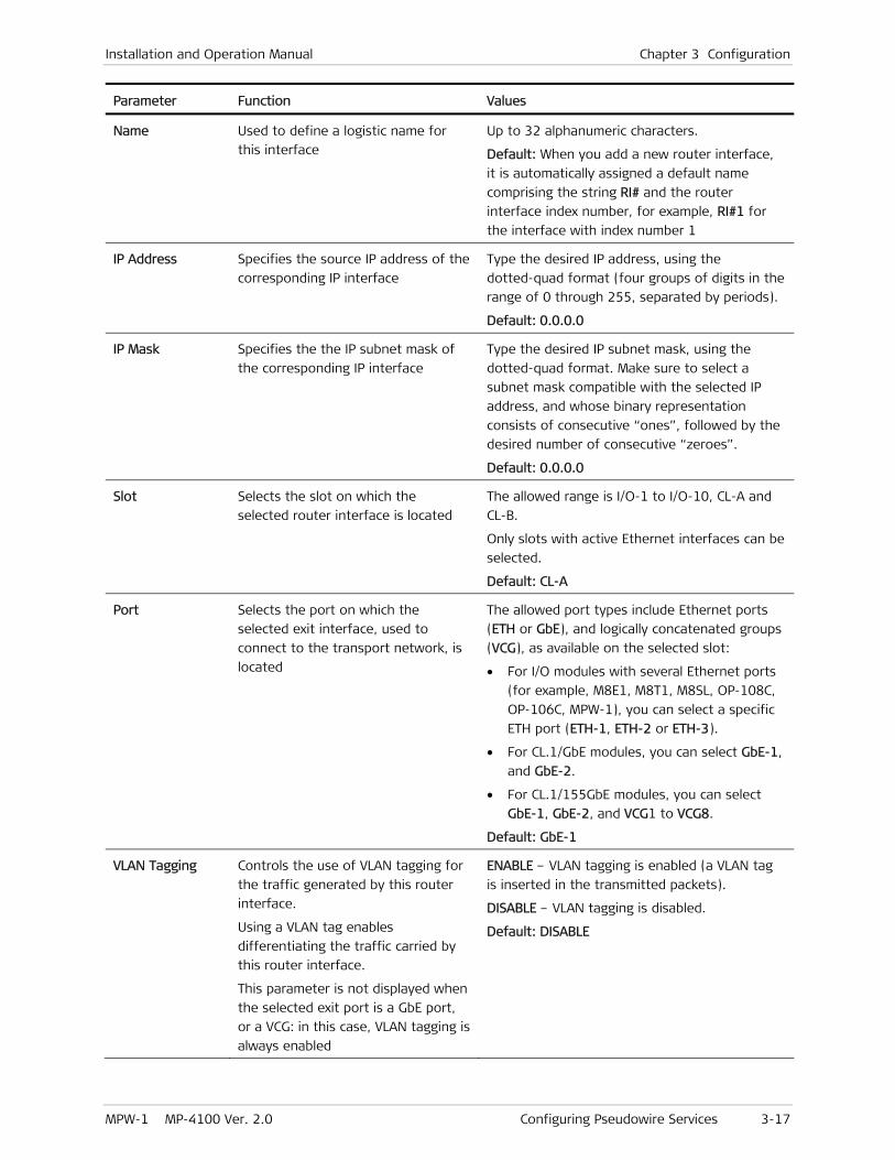
Installation and Operation Manual Chapter 3 Configuration
MPW-1 MP-4100 Ver. 2.0 Configuring Pseudowire Services 3-17
Parameter Function Values
Name Used to define a logistic name for
this interface
Up to 32 alphanumeric characters.
Default: When you add a new router interface,
it is automatically assigned a default name
comprising the string RI# and the router
interface index number, for example, RI#1 for
the interface with index number 1
IP Address Specifies the source IP address of the
corresponding IP interface
Type the desired IP address, using the
dotted-quad format (four groups of digits in the
range of 0 through 255, separated by periods).
Default: 0.0.0.0
IP Mask Specifies the the IP subnet mask of
the corresponding IP interface
Type the desired IP subnet mask, using the
dotted-quad format. Make sure to select a
subnet mask compatible with the selected IP
address, and whose binary representation
consists of consecutive “ones”, followed by the
desired number of consecutive “zeroes”.
Default: 0.0.0.0
Slot Selects the slot on which the
selected router interface is located
The allowed range is I/O-1 to I/O-10, CL-A and
CL-B.
Only slots with active Ethernet interfaces can be
selected.
Default: CL-A
Port Selects the port on which the
selected exit interface, used to
connect to the transport network, is
located
The allowed port types include Ethernet ports
(ETH or GbE), and logically concatenated groups
(VCG), as available on the selected slot:
• For I/O modules with several Ethernet ports
(for example, M8E1, M8T1, M8SL, OP-108C,
OP-106C, MPW-1), you can select a specific
ETH port (ETH-1, ETH-2 or ETH-3).
• For CL.1/GbE modules, you can select GbE-1,
and GbE-2.
• For CL.1/155GbE modules, you can select
GbE-1, GbE-2, and VCG1 to VCG8.
Default: GbE-1
VLAN Tagging Controls the use of VLAN tagging for
the traffic generated by this router
interface.
Using a VLAN tag enables
differentiating the traffic carried by
this router interface.
This parameter is not displayed when
the selected exit port is a GbE port,
or a VCG: in this case, VLAN tagging is
always enabled
ENABLE – VLAN tagging is enabled (a VLAN tag
is inserted in the transmitted packets).
DISABLE – VLAN tagging is disabled.
Default: DISABLE

Chapter 3 Configuration Installation and Operation Manual
3-18 Configuring Pseudowire Services MPW-1 MP-4100 Ver. 2.0
Parameter Function Values
VLAN ID Specifies the VLAN ID inserted in the
packets transmitted through this
router interface.
Using the MEF (Metropolitan Ethernet
Forum) terms, this VLAN ID indicates
the C-VLAN (customer’s edge VLAN).
This parameter is displayed only
when VLAN Tagging is ENABLE
The allowed range is 1 to 4094. The selected
VLAN ID must be unique per router interface,
but can be reused on different interfaces.
0 means that no VLAN ID has been selected.
Default: 1
Configuring Static Routes
You can configure up to 100 static routes in the whole Megaplex-4100.
To configure the static route parameters:
1. Navigate to the Configuration > Applications screen.
2. Select Router, and then select Static Route.
3. Select the desired static route index:
To modify an existing static route, enter its number in the Number field, or scroll using F and B
To define a new static route, select Add. The new static route is automatically assigned the next free number, in the range of 1 to 100.
4. To delete unnecessary static routes, select Delete (you will be requested to confirm).
Table 3-6 describes the static route parameters.
Table 3-6. Static Route Parameters
Parameter Function Values
Number Specifies the index number
representing the static route
The allowed range is 1 to 100.
Default: 1
IP Address Specifies the IP address of the static
route
Type the desired IP address, using the
dotted-quad format (four groups of digits in the
range of 0 through 255, separated by periods).
Default: 0.0.0.0
IP Mask Specifies the IP subnet mask of the
static route
Type the desired IP subnet mask, using the
dotted-quad format. Make sure to select a
subnet mask compatible with the selected IP
address, and whose binary representation
consists of consecutive “ones”, followed by the
desired number of consecutive “zeroes”.
Default: 0.0.0.0

Installation and Operation Manual Chapter 3 Configuration
MPW-1 MP-4100 Ver. 2.0 Configuring Pseudowire Services 3-19
Parameter Function Values
Next Hop Specifies an IP address to which the
packets will be sent, to enable
reaching the destination IP address.
This is usually the address of an IP
router port
Type in the next hop IP address using the
dotted-quad format.
To use the default gateway, leave this field at
the default value, 0.0.0.0.
Default: 0.0.0.0
Configuring the Pseudowire Peers
The peers (the pseudowire destinations) and the associated routing information are defined in a table that can include up to 100 destinations.
Each peer (destination) is assigned a unique index number. The index number is then used to specify the pseudowire destination, instead of directly providing the necessary destination information.
• Pseudowires configured on different MPW-1 modules must be configured with different peers, even if the destination address is the same.
• Different peers must not have the same destination IP address and the same Next Hop IP address (at least one of these parameters must be different). Therefore, if it necessary for several pseudowires to reach the same IP address, create separate router interfaces.
To configure peers parameters:
1. Navigate to the Configuration > Applications > Router screen.
2. Select the Peers option.
3. Select the desired peer index:
To modify an existing peer, enter its number in the Peer Number field, or scroll using F and B
To define a new peer, select Add. The new peer is automatically assigned the next free number, in the range of 1 to 100.
4. To delete unnecessary peers, select Delete (you will be requested to confirm).
Table 3-7 lists the peer parameters.
Table 3-7. Peer Parameters
Parameter Function Values
Peer Number Specifies the index number
representing the peer
The allowed range is 1 to 100.
Default: 1
Name Used to define a logistic name for
this peer
Up to 32 alphanumeric characters..
Default: When you add a new peer, it is
automatically assigned a default name
comprising the string Peer and the peer index
number, for example, Peer-1 for the peer with
index number 1
Note

Chapter 3 Configuration Installation and Operation Manual
3-20 Configuring Pseudowire Services MPW-1 MP-4100 Ver. 2.0
Parameter Function Values
Peer IP Address Specifies the IP address of the
peer
Enter the desired IP address in the dotted-quad
format.
Default: 0.0.0.0
Peer Next Hop
Address
Specifies the IP address of the
next port to which packets
directed to the selected peer will
be sent.
You need to specify a next hop IP
address only when the peer IP
address is not within the IP
subnet of the router interface
that will be used to send packets
to this peer.
The default value, 0.0.0.0, means
that no next hop IP address is
defined
Enter the desired IP address in the dotted-quad
format.
Default: 0.0.0.0
Pseudowire Parameters Configuration Sequence
The total number of pseudowires that can be defined on a MPW-1 module is as follows:
• For internal DS1 ports using the DS0 cross-connect mode: up to 16 pseudowires per internal DS1 port, for a maximum of 128 pseudowire for each MPW-1 module
• For internal DS1 ports using the DS1 cross-connect mode: a single pseudowire, using the whole bandwidth of internal DS1 port.
The pseudowire bandwidth depends on the type of port connected to the internal DS1 port:
• For E1 ports: 32 timeslots when using the Unframed mode, or 31 timeslots when using a Framed mode
• For T1 ports: 24 timeslots (possible only in the Framed mode)
The total number of pseudowires that can be defined on the whole Megaplex-4100 is 640.
The pseudowire configuration sequence includes the following main steps:
1. Preliminary actions: add a new pseudowire and define its logistic data, or select an existing pseudowire to modify its parameters or delete it.
2. Configure the general pseudowire parameters.
3. Configure the PSN parameters.
4. Configure the pseudowire service parameters
5. Configure the pseudowire attachment circuit parameters.
Note

Installation and Operation Manual Chapter 3 Configuration
MPW-1 MP-4100 Ver. 2.0 Configuring Pseudowire Services 3-21
The following sections provide guidelines for performing the required configuration activities, assuming that you are familiar with the Megaplex-4100 and its range of Ethernet services. If necessary, refer to the Megaplex-4100 Installation and Operation Manual for additional details.
The tasks needed to configure a pseudowire and its associated parameters are started from the Configuration > Applications > Multi-Service over PSN menu.
Preliminary Configuration Steps
To add a new pseudowire on a MPW-1 module:
1. Navigate to Configuration > Applications > Multi-Service over PSN, and then select PW.
2. To configure a new pseudowire, select Add. The new pseudowire number is automatically assigned the next free index number, in the range of 1 to 640.
3. Assign a logistic name to the pseudowire (up to 32 alphanumeric characters).
To modify or delete an existing pseudowire:
1. To select an existing pseudowire, enter its index number in the PW Number field.
The pseudowire I/O slot and its logistic name is automatically displayed.
2. You can now modify the pseudowire parameters. Note that the pseudowire type and the I/O slot on which it is processed cannot be changed even if the pseudowire is not in use: these parameters can be configured only when the pseudowire is first created (added). Therefore, to change these pseudowire parameters, first delete the pseudowire, and then create a new one with the desired parameters.
3. To delete an unnecessary pseudowire, select Delete (you will be requested to confirm).
Configuring General Pseudowire Parameters
The general pseudowire parameters determine the pseudowire encapsulation mode, and its PSN header structure. Other general pseudowire parameters are the pseudowire destination, OAM support, and some parameters used to fine-tune the payload handling.
To configure the general pseudowire parameters:
1. Navigate to the Configuration > Applications > Multi-Service over PSN > PW screen of the desired pseudowire.
2. Select General Parameters.
You will see the General Parameters screen of the desired pseudowire. The pseudowire index, its I/O slot and the assigned logistic name are automatically displayed at the top of the screen.
3. Obtain the prescribed parameters, and then use Table 3-8 for parameter descriptions and configuration guidelines.
Note

Chapter 3 Configuration Installation and Operation Manual
3-22 Configuring Pseudowire Services MPW-1 MP-4100 Ver. 2.0
Table 3-8. General Pseudowire Parameters
Parameter Function Values
PW Type Selects the encapsulation protocol
for the selected pseudowire
TDMoIP CE – Encapsulation using TDMoPSN
circuit emulation, can carry data and voice
timeslots, as well as unframed data.
HDLC – Encapsulation using the HDLCoPSN
protocol, for carrying HDLC traffic
CESoPSN – Encapsulation using the CESoPSN
protocol, for carrying framed data streams.
SAToP – Encapsulation using the SAToPSN
protocol, for carrying unframed data streams.
Default: TDMoIP CE
PSN Type Selects the type of PSN header for
the selected pseudowire
UDP/IP – UDP over IP.
MPLS/ETH – MPLS over Ethernet with standard
packet structure. In this case, only TDMoIP
Version V2 is used.
Default: UDP/IP
Peer Number Specifies the selected pseudowire
destination.
The destination is specified by
indicating the index of the
pseudowire peer. Make sure to select
one of the peers already defined in
accordance with the Configuring the Pseudowire Peers section
The available selections are 1 to 100.
Default: 1
OAM Mode Controls the use of use OAM
connectivity protocol for the selected
pseudowire.
The RAD proprietary implementation
of the OAM connectivity protocol
enables detecting loss of
communication with the pseudowire
destination and taking steps that
prevent the resulting flooding. The
protocol also enables checking that
the destination uses a compatible
configuration.
The selection must be compatible
with the equipment at the far end of
the connection. Contact RAD
Technical Support Department if you
need additional information
DISABLE – The use of the OAM connectivity
protocol is disabled.
PROPRIETARY – The use of the OAM connectivity
protocol is enabled. This is the recommended
selection. This option is available only when you
select V2 for Payload Format (part of the
pseudowire PSN parameters – see Table 3-9).
Default: PROPRIETARY

Installation and Operation Manual Chapter 3 Configuration
MPW-1 MP-4100 Ver. 2.0 Configuring Pseudowire Services 3-23
Parameter Function Values
Out PW Label For UDP/IP:
Specifies the UDP source port
number used by the pseudowire.
For MPLS/ETH:
Specifies the outer (tunnel) MPLS
label used by the pseudowire
The allowed range is 1 to 8063
Default: Same as the pseudowire index number
The allowed range is 16 to 1048575.
Default: Pseudowire index number + 15
In PW Label For UDP/IP:
Specifies the UDP destination port
number used by the pseudowire.
For MPLS/ETH:
Specifies the inbound MPLS label
used by the pseudowire
The allowed range is 1 to 8063
Default: Same as the pseudowire index number
The allowed range is 16 to 1048575.
Default: Pseudowire index number + 15
Configuring Pseudowire PSN Parameters
The pseudowire PSN parameters is used to configure the parameters that are used by the PSN to handle pseudowire traffic.
Some of the parameters depend on the PSN selection made as part of the pseudowire general parameters (see Table 3-8). In particular, for UDP/IP networks, the pseudowire label determines the source UDP port of a pseudowire. The method used to assign the source UDP port is as follows (unless explicitly stated otherwise, all the numbers are in hexadecimal notation):
• For TDMoIP CE pseudowires using packet payload Version V1:
During normal operation, the source UDP port is given by:
UDP Source Port = Pseudowire Label + 1
This means that during normal operation, the UDP ports numbers are in the range of 0 to 8191 decimal.
While the pseudowire is in the local fail state, the source UDP port changes to:
UDP Source Port = Pseudowire Label + 8000
This means that in the local fail state, the UDP ports numbers are higher than 8000 hexa (32768 decimal).
• For TDMoIP CE pseudowires using packet payload Version V2:
UDP Source Port = Pseudowire Label + 2000
This means that for TDMoIP CE pseudowires, all the UDP ports numbers are higher than 2000 hexa (8192 decimal). This also applies to HDLCoPSN.
As you may note, when you send to the same peer (destination IP address) packets using both payload Version V1 and payload Version V2, there is a potential for conflict. For example:
When you assign a certain label (for example, Out PW Label is set to 100) to a pseudowire using payload Version V1, the source UDP port is 101

Chapter 3 Configuration Installation and Operation Manual
3-24 Configuring Pseudowire Services MPW-1 MP-4100 Ver. 2.0
Now, you cannot assign the next label (Out PW Label of 101 in this example) to a pseudowire using payload Version V2, because the resulting source UDP port is also 101
So, you must skip (never use) the pseudowire label next to the label assigned to pseudowire payload Version V1, if the next pseudowire uses payload Version V2.
• For CESoPSN and SAToPSN pseudowires using packet payload Version V2:
UDP Source Port = Pseudowire Number + C000
This means that all the UDP ports numbers are higher than C000 hexa (49152 decimal).
To select the pseudowire PSN parameters:
1. Navigate to the Configuration > Applications > Multi-Service over PSN > PW screen of the desired pseudowire.
2. Select PSN Parameters.
You will see the PSN Parameters screen of the desired pseudowire. The pseudowire index, its I/O slot and logistic name, and the pseudowire type are automatically displayed at the top of the screen.
3. Obtain the prescribed parameters, and then use Table 3-9 for parameter descriptions and configuration guidelines.
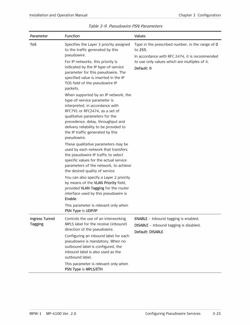
Installation and Operation Manual Chapter 3 Configuration
MPW-1 MP-4100 Ver. 2.0 Configuring Pseudowire Services 3-25
Table 3-9. Pseudowire PSN Parameters
Parameter Function Values
ToS Specifies the Layer 3 priority assigned
to the traffic generated by this
pseudowire.
For IP networks, this priority is
indicated by the IP type-of-service
parameter for this pseudowire. The
specified value is inserted in the IP
TOS field of the pseudowire IP
packets.
When supported by an IP network, the
type-of-service parameter is
interpreted, in accordance with
RFC791 or RFC2474, as a set of
qualitative parameters for the
precedence, delay, throughput and
delivery reliability to be provided to
the IP traffic generated by this
pseudowire.
These qualitative parameters may be
used by each network that transfers
the pseudowire IP traffic to select
specific values for the actual service
parameters of the network, to achieve
the desired quality of service
You can also specify a Layer 2 priority
by means of the VLAN Priority field,
provided VLAN Tagging for the router
interface used by this pseudowire is
Enable.
This parameter is relevant only when
PSN Type is UDP/IP
Type in the prescribed number, in the range of 0
to 255.
In accordance with RFC 2474, it is recommended
to use only values which are multiples of 4.
Default: 0
Ingress Tunnel
Tagging
Controls the use of an interworking
MPLS label for the receive (inbound)
direction of the pseudowire.
Configuring an inbound label for each
pseudowire is mandatory. When no
outbound label is configured, the
inbound label is also used as the
outbound label.
This parameter is relevant only when
PSN Type is MPLS/ETH
ENABLE – Inbound tagging is enabled.
DISABLE – Inbound tagging is disabled.
Default: DISABLE
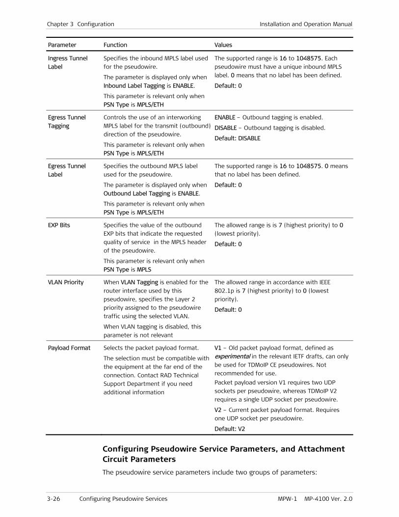
Chapter 3 Configuration Installation and Operation Manual
3-26 Configuring Pseudowire Services MPW-1 MP-4100 Ver. 2.0
Parameter Function Values
Ingress Tunnel
Label
Specifies the inbound MPLS label used
for the pseudowire.
The parameter is displayed only when
Inbound Label Tagging is ENABLE.
This parameter is relevant only when
PSN Type is MPLS/ETH
The supported range is 16 to 1048575. Each
pseudowire must have a unique inbound MPLS
label. 0 means that no label has been defined.
Default: 0
Egress Tunnel
Tagging
Controls the use of an interworking
MPLS label for the transmit (outbound)
direction of the pseudowire.
This parameter is relevant only when
PSN Type is MPLS/ETH
ENABLE – Outbound tagging is enabled.
DISABLE – Outbound tagging is disabled.
Default: DISABLE
Egress Tunnel
Label
Specifies the outbound MPLS label
used for the pseudowire.
The parameter is displayed only when
Outbound Label Tagging is ENABLE.
This parameter is relevant only when
PSN Type is MPLS/ETH
The supported range is 16 to 1048575. 0 means
that no label has been defined.
Default: 0
EXP Bits Specifies the value of the outbound
EXP bits that indicate the requested
quality of service in the MPLS header
of the pseudowire.
This parameter is relevant only when
PSN Type is MPLS
The allowed range is is 7 (highest priority) to 0
(lowest priority).
Default: 0
VLAN Priority When VLAN Tagging is enabled for the
router interface used by this
pseudowire, specifies the Layer 2
priority assigned to the pseudowire
traffic using the selected VLAN.
When VLAN tagging is disabled, this
parameter is not relevant
The allowed range in accordance with IEEE
802.1p is 7 (highest priority) to 0 (lowest
priority).
Default: 0
Payload Format Selects the packet payload format.
The selection must be compatible with
the equipment at the far end of the
connection. Contact RAD Technical
Support Department if you need
additional information
V1 – Old packet payload format, defined as
experimental in the relevant IETF drafts, can only
be used for TDMoIP CE pseudowires. Not
recommended for use.
Packet payload version V1 requires two UDP
sockets per pseudowire, whereas TDMoIP V2
requires a single UDP socket per pseudowire.
V2 – Current packet payload format. Requires
one UDP socket per pseudowire.
Default: V2
Configuring Pseudowire Service Parameters, and Attachment Circuit Parameters
The pseudowire service parameters include two groups of parameters:
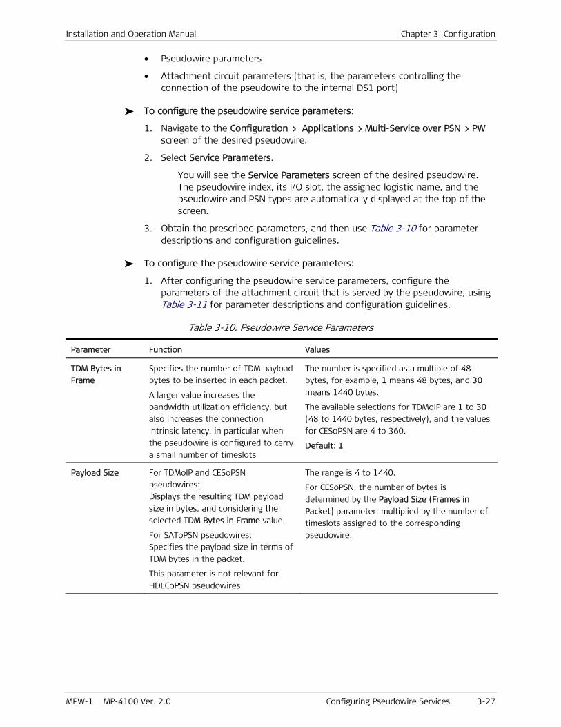
Installation and Operation Manual Chapter 3 Configuration
MPW-1 MP-4100 Ver. 2.0 Configuring Pseudowire Services 3-27
• Pseudowire parameters
• Attachment circuit parameters (that is, the parameters controlling the connection of the pseudowire to the internal DS1 port)
To configure the pseudowire service parameters:
1. Navigate to the Configuration > Applications > Multi-Service over PSN > PW screen of the desired pseudowire.
2. Select Service Parameters.
You will see the Service Parameters screen of the desired pseudowire. The pseudowire index, its I/O slot, the assigned logistic name, and the pseudowire and PSN types are automatically displayed at the top of the screen.
3. Obtain the prescribed parameters, and then use Table 3-10 for parameter descriptions and configuration guidelines.
To configure the pseudowire service parameters:
1. After configuring the pseudowire service parameters, configure the parameters of the attachment circuit that is served by the pseudowire, using Table 3-11 for parameter descriptions and configuration guidelines.
Table 3-10. Pseudowire Service Parameters
Parameter Function Values
TDM Bytes in
Frame
Specifies the number of TDM payload
bytes to be inserted in each packet.
A larger value increases the
bandwidth utilization efficiency, but
also increases the connection
intrinsic latency, in particular when
the pseudowire is configured to carry
a small number of timeslots
The number is specified as a multiple of 48
bytes, for example, 1 means 48 bytes, and 30
means 1440 bytes.
The available selections for TDMoIP are 1 to 30
(48 to 1440 bytes, respectively), and the values
for CESoPSN are 4 to 360.
Default: 1
Payload Size For TDMoIP and CESoPSN
pseudowires:
Displays the resulting TDM payload
size in bytes, and considering the
selected TDM Bytes in Frame value.
For SAToPSN pseudowires:
Specifies the payload size in terms of
TDM bytes in the packet.
This parameter is not relevant for
HDLCoPSN pseudowires
The range is 4 to 1440.
For CESoPSN, the number of bytes is
determined by the Payload Size (Frames in
Packet) parameter, multiplied by the number of
timeslots assigned to the corresponding
pseudowire.
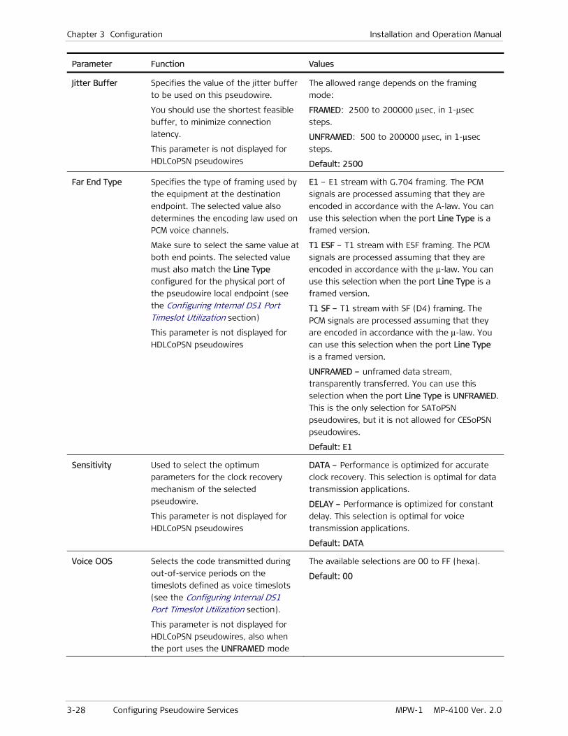
Chapter 3 Configuration Installation and Operation Manual
3-28 Configuring Pseudowire Services MPW-1 MP-4100 Ver. 2.0
Parameter Function Values
Jitter Buffer Specifies the value of the jitter buffer
to be used on this pseudowire.
You should use the shortest feasible
buffer, to minimize connection
latency.
This parameter is not displayed for
HDLCoPSN pseudowires
The allowed range depends on the framing
mode:
FRAMED: 2500 to 200000 μsec, in 1-μsec
steps.
UNFRAMED: 500 to 200000 μsec, in 1-μsec
steps.
Default: 2500
Far End Type Specifies the type of framing used by
the equipment at the destination
endpoint. The selected value also
determines the encoding law used on
PCM voice channels.
Make sure to select the same value at
both end points. The selected value
must also match the Line Type
configured for the physical port of
the pseudowire local endpoint (see
the Configuring Internal DS1 Port Timeslot Utilization section)
This parameter is not displayed for
HDLCoPSN pseudowires
E1 – E1 stream with G.704 framing. The PCM
signals are processed assuming that they are
encoded in accordance with the A-law. You can
use this selection when the port Line Type is a
framed version.
T1 ESF – T1 stream with ESF framing. The PCM
signals are processed assuming that they are
encoded in accordance with the μ-law. You can
use this selection when the port Line Type is a
framed version.
T1 SF – T1 stream with SF (D4) framing. The
PCM signals are processed assuming that they
are encoded in accordance with the μ-law. You
can use this selection when the port Line Type
is a framed version.
UNFRAMED – unframed data stream,
transparently transferred. You can use this
selection when the port Line Type is UNFRAMED.
This is the only selection for SAToPSN
pseudowires, but it is not allowed for CESoPSN
pseudowires.
Default: E1
Sensitivity Used to select the optimum
parameters for the clock recovery
mechanism of the selected
pseudowire.
This parameter is not displayed for
HDLCoPSN pseudowires
DATA – Performance is optimized for accurate
clock recovery. This selection is optimal for data
transmission applications.
DELAY – Performance is optimized for constant
delay. This selection is optimal for voice
transmission applications.
Default: DATA
Voice OOS Selects the code transmitted during
out-of-service periods on the
timeslots defined as voice timeslots
(see the Configuring Internal DS1 Port Timeslot Utilization section).
This parameter is not displayed for
HDLCoPSN pseudowires, also when
the port uses the UNFRAMED mode
The available selections are 00 to FF (hexa).
Default: 00

Installation and Operation Manual Chapter 3 Configuration
MPW-1 MP-4100 Ver. 2.0 Configuring Pseudowire Services 3-29
Parameter Function Values
Data OOS Selects the code transmitted by the
port during out-of-service periods on
the timeslots defined as data
timeslots (see the Configuring Internal DS1 Port Timeslot Utilization section).
The selected code is also sent during
out-of-service periods instead of the
external data stream when the
UNFRAMED mode is used
The available selections are 00 to FF (hexa).
Default: 00
OOS Signaling Determines the state of the signaling
bits sent to the internal DS1 port
connected to the selected
pseudowire during out-of-service
periods.
This parameter is displayed only
when the attached internal DS1 port
is configured with Signaling = YES
FORCED IDLE – The signaling bits are forced to
the idle state (05 hexa) during out-of-service
periods.
FORCED BUSY – The signaling bits are forced to
the busy state (0F hexa) during out-of-service
periods.
Default: FORCED IDLE
Attachment
Circuit
Opens the pseudowire attachment
circuit parameters screen
See Table 3-11
Table 3-11. Pseudowire Attachment Circuit Parameters
Parameter Function Values
Slot Selects the I/O slot number on which
the pseudowire will be terminated.
You can select only I/O slots in which
MPW-1 modules are programmed
IO-1 to IO-10.
Default: IO-1
Int DS1 Number Selects the internal DS1 port of the
selected MPW-1 to which the
pseudowire is connected
The allowed range is 1 to 8.
Default: 1
Time Slots Displays the timeslot assignment
submenu for this pseudowire.
This item is displayed only when the
internal DS1 port uses the DS0
cross-connect mode
See below
Selecting Internal DS1 Timeslots Connected to a Pseudowire
The internal DS1 ports provide a connection point between TDM traffic arriving from other modules and the pseudowires supported by MPW-1 (see the Configuring Internal DS1 Port Timeslot Utilization section starting on page 3-11). Each pseudowire can be connected to only one internal DS1 port.
When the internal DS1 port to which the pseudowire uses the DS0 cross-connect mode, you must specify the timeslots to be served by the pseudowire.
Chapter 3 Configuration Installation and Operation Manual
3-30 Configuring Pseudowire Services MPW-1 MP-4100 Ver. 2.0
To select the timeslots connected to the pseudowire:
1. Navigate to the Configuration > Applications > Multi-Service over PSN > PW > Service Parameters screen of the desired pseudowire.
2. After selecting the prescribed internal DS1 port, select Time Slots.
3. Initially, the screen is empty. Select Add to add the desired number of timeslot selection fields.
4. Sequentially select each timeslot selection field, and enter the number of the prescribed timeslot.
5. When done, save the selections by typing s.
6. The selected timeslots are listed now in a single row, and a new item, Delete Range, appears. This item enables to delete the current selections: type the desired numbers in the format displayed on the screen and then confirm.
Configuring Fault Propagation for MPW-1 Modules
The fault propagation function can be used to notify equipment at a far end port that a fault condition has been detected at a local port.
MPW-1 modules support unidirectional fault propagation for pseudowires: if a problem is detected on a pseudowire, the attached physical port receives a fault indication.
Fault propagation cannot be enabled for ports with redundancy enabled.
For the supervision terminal, use Configuration > System > Fault Propagation (for instructions, refer to the Megaplex-4100 Installation and Operation Manual).
To configure fault propagation:
1. On the Configuration > System menu, select Fault Propagation, and then press <Enter>.
2. Select Fault Propagation to toggle the selection: to configure fault propagation, select ENABLE.
3. Select Interfaces to display the interface configuration screen. If no interfaces has yet been mapped for fault propagation, the screen is empty.
4. To add fault propagation between a new pair of interfaces, type A (Add) and then press <Enter>.
You will see the Interface configuration data form.
5. Select the first endpoint, Slot A: you will see a submenu which lists I/O slots in which modules with ports that support fault propagation are installed, or at least programmed. For pseudowires, select None.
6. Select the desired pseudowire index number for Slot A.
7. After selecting the desired pseudowire, repeat the selections for the physical endpoint (Slot B and Port B) of the pseudowire.
8. After specifying the two endpoints, select the fault propagation direction by means of the Mode field. The only selection valid for pseudowires is UniDirectional(A- > B): fault conditions are reported only from endpoint A (the selected pseudowire) to endpoint B.

Installation and Operation Manual Chapter 3 Configuration
MPW-1 MP-4100 Ver. 2.0 Configuring Pseudowires as System Timing References 3-31
9. Type s to save the configuration.
10. After completing the configuration, the new set of endpoints appear on the Interfaces screen.
11. Repeat the procedure for any additional endpoints.
3.5 Configuring Pseudowires as System Timing References
MPW-1 has independent adaptive clock recovery mechanisms for each pseudowire, which recover the original timing (clock rate) of the far end source of each pseudowire.
The recovered mechanisms can provide the recovered clock signals to serve as timing references for the Megaplex-4100 nodal timing subsystem (refer to the Megaplex-4100 Installation and Operation Manual for a description of this subsystem).
To select pseudowires as timing reference, first select the appropriate pseudowires of the desired MPW-1 modules, and then include them in the master and/or fallback list of clock sources.
You can select up to 10 pseudowires as master clock sources, and up to 10 additional pseudowires as fallback sources, for a total of 20 pseudowires per Megaplex-4100. Any pseudowire can be included only once, either as master or as fallback source.
You cannot select HDLCoPSN pseudowires as clock sources.
To configure the recovered clock sources that can be used as timing references:
1. Navigate to Configuration > System > Clock Source.
2. Select Recovered.
Table 3-12 describes the recovered clock source parameters.
Table 3-12. Recovered Clock Source Parameters
Parameter Function Values
Slot Displays the slot of the selected
pseudowire
The allowed range is I/O-1 to I/O-10.
Default: I/O-1
Type Displays the clock source type Always ADAPTIVE
ID Specifies the index number of the
recovered clock source to be
configured
The allowed range is 1 to 20.
Default: 1
PW Number Specifies the pseudowire index
number that will be the source with
the selected index number
The allowed range is 1 to 640.
1 – number of allowed pseudowire per device.
Default: the first index number of an existing
pseudowire
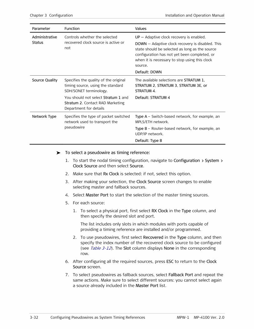
Chapter 3 Configuration Installation and Operation Manual
3-32 Configuring Pseudowires as System Timing References MPW-1 MP-4100 Ver. 2.0
Parameter Function Values
Administrative
Status
Controls whether the selected
recovered clock source is active or
not
UP — Adaptive clock recovery is enabled.
DOWN — Adaptive clock recovery is disabled. This
state should be selected as long as the source
configuration has not yet been completed, or
when it is necessary to stop using this clock
source.
Default: DOWN
Source Quality Specifies the quality of the original
timing source, using the standard
SDH/SONET terminology.
You should not select Stratum 1 and
Stratum 2. Contact RAD Marketing
Department for details
The available selections are STRATUM 1,
STRATUM 2, STRATUM 3, STRATUM 3E, or
STRATUM 4.
Default: STRATUM 4
Network Type Specifies the type of packet switched
network used to transport the
pseudowire
Type A – Switch-based network, for example, an
MPLS/ETH network.
Type B – Router-based network, for example, an
UDP/IP network.
Default: Type B
To select a pseudowire as timing reference:
1. To start the nodal timing configuration, navigate to Configuration > System > Clock Source and then select Source.
2. Make sure that Rx Clock is selected: if not, select this option.
3. After making your selection, the Clock Source screen changes to enable selecting master and fallback sources.
4. Select Master Port to start the selection of the master timing sources.
5. For each source:
1. To select a physical port, first select RX Clock in the Type column, and then specify the desired slot and port.
The list includes only slots in which modules with ports capable of providing a timing reference are installed and/or programmed.
2. To use pseudowires, first select Recovered in the Type column, and then specify the index number of the recovered clock source to be configured (see Table 3-12). The Slot column displays None in the corresponding row.
6. After configuring all the required sources, press ESC to return to the Clock Source screen.
7. To select pseudowires as fallback sources, select Fallback Port and repeat the same actions. Make sure to select different sources: you cannot select again a source already included in the Master Port list.

Installation and Operation Manual Chapter 3 Configuration
MPW-1 MP-4100 Ver. 2.0 Viewing Ethernet Flows Associated with Pseudowires 3-33
3.6 Viewing Ethernet Flows Associated with Pseudowires
After performing the pseudowire configuration activities listed above, you can view the Ethernet traffic flows that are used by pseudowires.
For the supervision terminal, use Configuration > Applications > Ethernet Services > Flows (for instructions, refer to the Megaplex-4100 Installation and Operation Manual).
The Ethernet flow of each pseudowire is an E-line flow, and therefore it has exactly two bridge ports:
• One bridge port is the router interface used by corresponding pseudowire
• The other bridge port is the selected exit port:
For I/O modules with Ethernet ports (for example, M8E1, M8T1, M8SL, OP-108C, OP-106C, MPW-1): a specific ETH port (ETH-1, ETH-2 or ETH-3).
For CL.1/GbE modules: the GbE port, GbE-1 or GbE-2.
For CL.1/155GbE modules: a GbE port, GbE-1 or GbE-2, or a virtually concatenated group, VCG1 to VCG8.

Chapter 3 Configuration Installation and Operation Manual
3-34 Viewing Ethernet Flows Associated with Pseudowires MPW-1 MP-4100 Ver. 2.0

MPW-1 MP-4100 Ver. 2.0 Monitoring Performance 4-1
Chapter 4
Troubleshooting and Diagnostics This Chapter explains the MPW-1-specific troubleshooting and diagnostic functions. These functions include:
• Collection of MPW-1 performance monitoring and status data – presented in Section 4.1.
• Detection of configuration (sanity) errors – presented in Section 4.2. This section covers only the MPW-1 specific sanity errors: for other sanity errors, refer to the Megaplex-4100 Installation and Operation Manual.
• Interpretation of alarms – presented in Section 4.3. This section covers only the MPW-1 specific alarms: for other alarms, refer to the Megaplex-4100 Installation and Operation Manual.
• Troubleshooting instructions: Section 4.4.
• Diagnostic tests for checking transmission paths – presented in Section 4.5.
The information presented in this Chapter supplements the general Megaplex-4100 troubleshooting and diagnostics instructions contained in the Megaplex-4100 Installation and Operation Manual.
If you need additional support for this product, see Section 4.6 for technical support information.
4.1 Monitoring Performance
This section presents the MPW-1 performance statistics and status data relevant to TDMoIP applications. For other monitoring tasks, refer to the Megaplex-4100 Installation and Operation Manual.
When using the Megaplex-4100 supervision utility, the performance monitoring functions are accessed under the Monitoring menu.
MPW-1 collects the following types of performance monitoring and status data:
• For MPW-1 Ethernet physical ports:
Status data for each Ethernet port, and SFP data when the MPW-1 Ethernet ports are equipped with optical interfaces
Transmission performance statistics
When using the Megaplex-4100 supervision utility, the MPW-1 Ethernet physical port performance monitoring functions are accessed after selecting the desired module under Monitoring > Physical Layer > I/O > Ethernet.
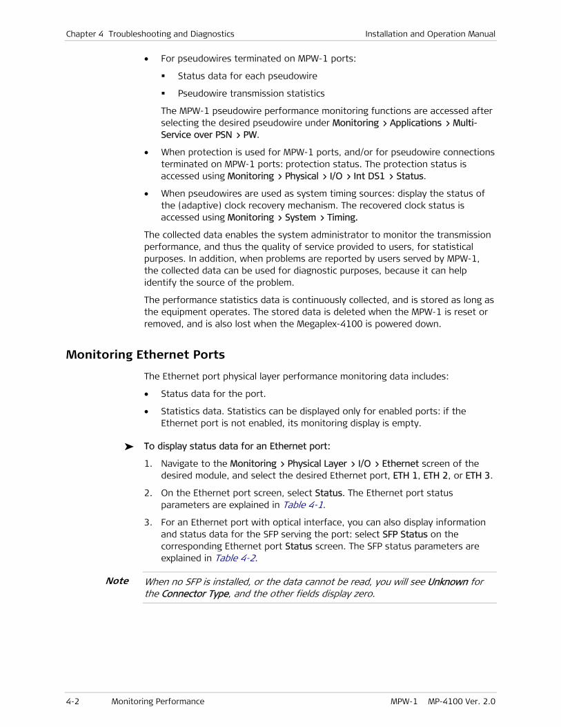
Chapter 4 Troubleshooting and Diagnostics Installation and Operation Manual
4-2 Monitoring Performance MPW-1 MP-4100 Ver. 2.0
• For pseudowires terminated on MPW-1 ports:
Status data for each pseudowire
Pseudowire transmission statistics
The MPW-1 pseudowire performance monitoring functions are accessed after selecting the desired pseudowire under Monitoring > Applications > Multi-Service over PSN > PW.
• When protection is used for MPW-1 ports, and/or for pseudowire connections terminated on MPW-1 ports: protection status. The protection status is accessed using Monitoring > Physical > I/O > Int DS1 > Status.
• When pseudowires are used as system timing sources: display the status of the (adaptive) clock recovery mechanism. The recovered clock status is accessed using Monitoring > System > Timing.
The collected data enables the system administrator to monitor the transmission performance, and thus the quality of service provided to users, for statistical purposes. In addition, when problems are reported by users served by MPW-1, the collected data can be used for diagnostic purposes, because it can help identify the source of the problem.
The performance statistics data is continuously collected, and is stored as long as the equipment operates. The stored data is deleted when the MPW-1 is reset or removed, and is also lost when the Megaplex-4100 is powered down.
Monitoring Ethernet Ports
The Ethernet port physical layer performance monitoring data includes:
• Status data for the port.
• Statistics data. Statistics can be displayed only for enabled ports: if the Ethernet port is not enabled, its monitoring display is empty.
To display status data for an Ethernet port:
1. Navigate to the Monitoring > Physical Layer > I/O > Ethernet screen of the desired module, and select the desired Ethernet port, ETH 1, ETH 2, or ETH 3.
2. On the Ethernet port screen, select Status. The Ethernet port status parameters are explained in Table 4-1.
3. For an Ethernet port with optical interface, you can also display information and status data for the SFP serving the port: select SFP Status on the corresponding Ethernet port Status screen. The SFP status parameters are explained in Table 4-2.
When no SFP is installed, or the data cannot be read, you will see Unknown for the Connector Type, and the other fields display zero.
Note
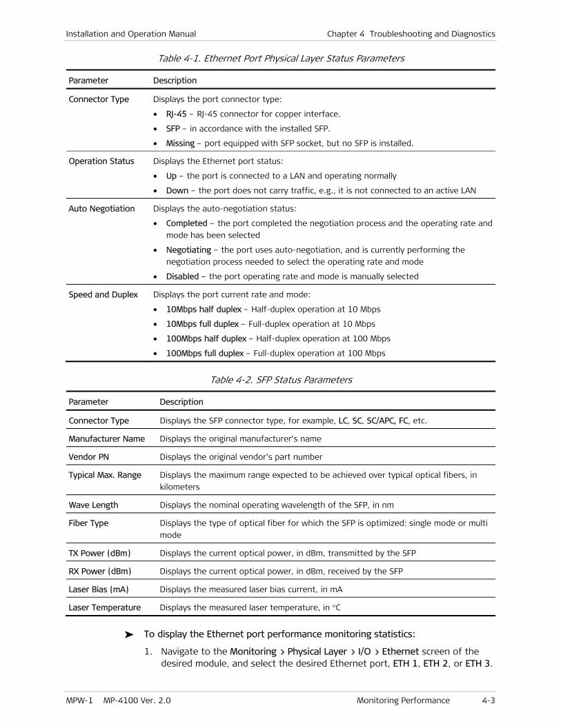
Installation and Operation Manual Chapter 4 Troubleshooting and Diagnostics
MPW-1 MP-4100 Ver. 2.0 Monitoring Performance 4-3
Table 4-1. Ethernet Port Physical Layer Status Parameters
Parameter Description
Connector Type Displays the port connector type:
• RJ-45 – RJ-45 connector for copper interface.
• SFP – in accordance with the installed SFP.
• Missing – port equipped with SFP socket, but no SFP is installed.
Operation Status Displays the Ethernet port status:
• Up – the port is connected to a LAN and operating normally
• Down – the port does not carry traffic, e.g., it is not connected to an active LAN
Auto Negotiation Displays the auto-negotiation status:
• Completed – the port completed the negotiation process and the operating rate and
mode has been selected
• Negotiating – the port uses auto-negotiation, and is currently performing the
negotiation process needed to select the operating rate and mode
• Disabled – the port operating rate and mode is manually selected
Speed and Duplex Displays the port current rate and mode:
• 10Mbps half duplex – Half-duplex operation at 10 Mbps
• 10Mbps full duplex – Full-duplex operation at 10 Mbps
• 100Mbps half duplex – Half-duplex operation at 100 Mbps
• 100Mbps full duplex – Full-duplex operation at 100 Mbps
Table 4-2. SFP Status Parameters
Parameter Description
Connector Type Displays the SFP connector type, for example, LC, SC, SC/APC, FC, etc.
Manufacturer Name Displays the original manufacturer’s name
Vendor PN Displays the original vendor’s part number
Typical Max. Range Displays the maximum range expected to be achieved over typical optical fibers, in
kilometers
Wave Length Displays the nominal operating wavelength of the SFP, in nm
Fiber Type Displays the type of optical fiber for which the SFP is optimized: single mode or multi
mode
TX Power (dBm) Displays the current optical power, in dBm, transmitted by the SFP
RX Power (dBm) Displays the current optical power, in dBm, received by the SFP
Laser Bias (mA) Displays the measured laser bias current, in mA
Laser Temperature Displays the measured laser temperature, in °C
To display the Ethernet port performance monitoring statistics:
1. Navigate to the Monitoring > Physical Layer > I/O > Ethernet screen of the desired module, and select the desired Ethernet port, ETH 1, ETH 2, or ETH 3.

Chapter 4 Troubleshooting and Diagnostics Installation and Operation Manual
4-4 Monitoring Performance MPW-1 MP-4100 Ver. 2.0
2. On the Ethernet port screen, select Statistics.
You will see the Statistics screen for the selected Ethernet port. The screen consists of three pages:
To continue to the next page, type n (next)
To return to the previous page, type p (previous).
Table 4-3 explains the Ethernet port statistics parameters.
The information is accumulated continuously while the MPW-1 operates, and is automatically refreshed every few seconds. You can clear the displayed statistics (that is, reset the displayed performance monitoring counters) by typing C. The counters are also reset when the MPW-1 is powered up.
Table 4-3. Ethernet Port Physical Layer Performance Monitoring Statistics
Parameter Description
Rx Total Frames Total number of frames received through the corresponding Ethernet port
Rx Total Octets Total number of data octets carried by all frames received through the
corresponding Ethernet port
Rx Correct Frames Total number of good frames received through the corresponding Ethernet
port
Rx FCS Errors Total number of frames received by the corresponding Ethernet port which
has an invalid FCS, but met the following conditions:
• Frame data length is between 64 bytes, and 1518 or 1536 bytes
(depending on mode)
• Collision event has not been detected
• Late collision event has not been detected
Rx Jabber Errors Total number of frames received by the corresponding Ethernet port during
jabber (such frames are frames with a data field length exceeding 1518 or
1536 bytes, and also having invalid CRC)
Rx Fragments Errors Number of fragmented frames received at the corresponding Ethernet port (a
fragmented frame is a frame with a data field length less than 64 bytes and
invalid CRC, for which no collision event and no late collision event have not
been detected during its reception)
Rx Pause Frames Total number of pause frames (used for flow control) received through the
corresponding Ethernet port
Rx Undersized Frames Total number of frames with size less than 64 bytes received through the
corresponding Ethernet port
Rx Oversized Frames Total number of frames with size more than the maximum allowed received
through the corresponding Ethernet port
Rx Discard Frames Total number of valid frames received by the corresponding Ethernet port
that have been discarded because of a lack of buffer space. This includes
frames discarded at ingress, as well as those dropped due to priority and
congestion considerations at the output queues
Rx Errors Total number of frames received by the corresponding Ethernet port that had
other types of errors

Installation and Operation Manual Chapter 4 Troubleshooting and Diagnostics
MPW-1 MP-4100 Ver. 2.0 Monitoring Performance 4-5
Parameter Description
Rx Unicast Frames Total number of good unicast frames received through the corresponding
Ethernet port
Rx Multicast Frames Total number of good multicast frames received through the corresponding
Ethernet port
Rx Broadcast Frames Total number of good broadcast frames received through the corresponding
Ethernet port
Rx 64 Octets Total number of 64-byte frames received through the corresponding Ethernet
port
Rx 65-127 Octets Total number of frames with size of 65 to 127 bytes received through the
corresponding Ethernet port
Rx 128-255 Octets Total number of frames with size of 128 to 255 bytes received through the
corresponding Ethernet port
Rx 256-511 Octets Total number of frames with size of 256 to 511 bytes received through the
corresponding Ethernet port
Rx 512-1023 Octets Total number of frames with size of 512 to 1023 bytes received through the
corresponding Ethernet port
Rx 1024-long Octets Total number of frames with size of 1024 up to 1600 bytes received through
the corresponding Ethernet port
Tx Total Frames Total number of good frames transmitted by the corresponding Ethernet port
Tx Total Octets Total number of data octets carried by all the good frames transmitted by the
corresponding Ethernet port
Tx Correct Frames Total number good frames transmitted by the corresponding Ethernet port
Tx Collisions Total number of collisions detected at the corresponding Ethernet port
Tx Unicast Frames Total number of good unicast frames transmitted by the corresponding
Ethernet port
Tx Multicast Frames Total number of good multicast frames transmitted by the corresponding
Ethernet port
Tx Broadcast Frames Total number of good broadcast frames transmitted by the corresponding
Ethernet port

Chapter 4 Troubleshooting and Diagnostics Installation and Operation Manual
4-6 Monitoring Performance MPW-1 MP-4100 Ver. 2.0
Monitoring Pseudowire Services
The pseudowire services monitoring functions include:
• Status data for each pseudowire terminated on MPW-1 ports
• Diagnostic statistics for the current 15-minute interval (interval 0), any previous 15-minute interval within the last 24 hours for which valid performance data exists, and data for the current 24-hour interval.
• Transmission performance statistics.
The statistics data is continuously collected, and is stored as long as the equipment operates. The stored data is deleted when the MPW-1 is reset or removed, and is also lost when the Megaplex-4100 is powered down.
You can clear the displayed statistics (that is, reset the monitoring counters) by typing C. The counters are also reset when the MPW-1 is powered up.
The collected data enables the system administrator to monitor the pseudowire performance, and thus the quality of service provided to users, for statistical purposes. In addition, when problems are reported by users served by MPW-1, the collected data can be used for diagnostic purposes, because it can help identify the source of the problem.
Displaying Pseudowire Status Data
To display status data for pseudowires:
1. Navigate to Monitoring > Applications > Multi-Service over PSN > PW screen, and select Status.
2. The Status screen displays the status data for the first pseudowire. To select another pseudowire you can either specify its index number, in the range of 1 to 640, or sequentially scroll forward or backward by typing F or B. Unused index numbers are automatically skipped.
3. After selecting a pseudowire, the information displayed on the screen is updated to display its status.
Table 4-4 explains the pseudowire status parameters.
Table 4-4. Pseudowire Status Parameters
Parameter Description
PW Number Used to select the pseudowire with the desired index number.
Megaplex-4100 supports up to 640 pseudowires (the maximum number per
MPW-1 is 128)
PW Slot Displays the I/O slot number, I/O-1 to I/O-10, of the MPW-1 module which
terminates the selected pseudowire
Name Displays the logistic name assigned to the selected pseudowire.
An empty string means that no name has been assigned to the selected
pseudowire

Installation and Operation Manual Chapter 4 Troubleshooting and Diagnostics
MPW-1 MP-4100 Ver. 2.0 Monitoring Performance 4-7
Parameter Description
PW Type Displays the pseudowire type (protocol):
TDMoIP CE – Pseudowire using TDMoPSN circuit emulation.
HDLC – Pseudowire using the HDLCoPSN protocol
CESoPSN – Pseudowire using the CESoPSN protocol
SAToP – Pseudowire using the SAToPSN protocol
Peer IP Address Displays the pseudowire destination IP address (the peer IP address)
Next Hop MAC Address Displays the MAC address of the next port on the path to the destination (the
next hop MAC address)
Connectivity Status Displays the connectivity status of the selected pseudowire:
OK – the pseudowire carries traffic, and both the remote and the local
pseudowire endpoints receive Ethernet frames. However, there may be
problems such as sequence errors, underflows, overflows, etc., which may be
displayed using the Statistics function.
LOCAL FAIL – a failure has been detected at the local pseudowire endpoint.
REMOTE FAIL – a failure is reported by the remote pseudowire endpoint.
UNAVAILABLE – the pseudowire reports loss of connectivity (it did not receive
neither OAM, nor data packets for 10 seconds or more (OAM link then reports
loss of synchronization). This is often caused by network problems, or
configuration errors.
VALIDATION FAIL – the remote pseudowire endpoint replied to OAM packets,
but there is a configuration mismatch (the configuration parameters used at
two endpoints of the pseudowire are different)
Displaying Pseudowire Diagnostic Statistics
You can display, for each pseudowire, the desired diagnostic statistics view:
• Current 15-minute interval (interval 0)
• Any previous 15-minute interval within the last 24 hours, for which valid performance data exists
• Total for the current 24-hour interval.
To display diagnostic statistics data for pseudowires:
1. Navigate to Monitoring > Applications > Multi-Service over PSN > PW screen, and select Statistics.
2. On the Statistics screen, select Intervals.
3. The Intervals screen displays the number of the first pseudowire, the number of the I/O slot on which it is terminated, and an interval selection menu. To select another pseudowire you can either specify its index number, in the range of 1 to 640, or sequentially scroll forward or backward by typing F or B. Unused index numbers are automatically skipped.
4. Select the desired display view:
1. To display statistics for the current 15-minute interval, select Current (15 min).

Chapter 4 Troubleshooting and Diagnostics Installation and Operation Manual
4-8 Monitoring Performance MPW-1 MP-4100 Ver. 2.0
2. To display statistics for a selected previous 15-minute interval, select Select Interval.
3. To display the total statistics for the current 24-hour interval, select Total (24 hours).
You can clear the displayed statistics (that is, reset the monitoring counters) by typing C: all the counters are simultaneously reset. The counters are also reset when the MPW-1 is powered up.
Table 4-5 explains the pseudowire diagnostic (interval) statistics parameters.
Table 4-5. Pseudowire Diagnostic (Interval) Statistics Parameters
Parameter Description
PW Number Used to select the pseudowire with the desired index number.
Megaplex-4100 supports up to 640 pseudowires (the maximum number per MPW-1
is 128)
Slot Displays the I/O slot number, I/O-1 to I/O-10, of the MPW-1 module which
terminates the selected pseudowire
Name Displays the logistic name assigned to the selected pseudowire.
An empty string means that no name has been assigned to the selected pseudowire
Interval Number After selecting Select Interval, enter the number of the desired 15-minute interval
whose statistics you wish to display.
The allowed range is 1 to 96. The actual maximum depends on the number of
intervals for which valid data is available, which is displayed by the Valid Intervals.
Sequence Errors
Seconds
Displays the number of seconds during which sequence errors have been detected.
In accordance with the applicable standards, the transmitted packets carry a
sequence number that is automatically assigned, such that consecutive packets are
automatically consecutive sequence numbers. At the receive side, these numbers are
checked by the receive mechanism, which expects each new incoming packet to
carry the next number in the sequence, relative to the previous one (i.e., packet 5
must be received after packet 4). Any deviation from the this rule indicates a
problem with packet flow integrity (and hence with the pseudowire payload (data or
voice) integrity), and in this case the sequence errors count is incremented by 1.
There are two main reasons for a sequence error event:
• One or more packets have been lost somewhere in the network.
• Packets have been reordered within the network. Packet reordering may occur
due to queuing mechanisms, rerouting by the network, or when the router
updates include very large routing tables

Installation and Operation Manual Chapter 4 Troubleshooting and Diagnostics
MPW-1 MP-4100 Ver. 2.0 Monitoring Performance 4-9
Parameter Description
Jitter Buffer
Underflows Seconds
Displays the number of seconds during which at least one jitter buffer underflow
event has been detected.
MPW-1 is equipped with a Packet Delay Variation Tolerance buffer, also called a
“jitter buffer”, which is used to automatically compensate for packet network delay
variation (jitter). Each pseudowire has its own jitter buffer. Although packets leave
the transmitting MPW-1 at a constant rate, they will usually reach the far end at a
rate which is not constant, because in practice the network transmission delay varies
(due to factors such as congestion, rerouting, queuing mechanisms, transport over
wireless or half-duplex media, etc.).
TDM equipment at both ends of a pseudowire require a constant flow of data, and
cannot tolerate delay variation. Therefore, the receive side jitter buffer is required to
provide the TDM equipment with a synchronous and constant flow.
For this purpose, when a pseudowire is set up (and at any time after communication
is restored), the jitter buffer is loaded with packets up to its middle point: only after
this point it starts outputting TDM data towards the connected TDM equipment. The
stored packets assure that the TDM equipment will continue receiving data even if
the network delay momentarily increases. Obviously, if packets are delayed too long,
the buffer is gradually emptied out until it underflows (this situation is called buffer
starvation, and it affects the end-to-end voice/data integrity).
Each underflow event increases the jitter buffer underflow counter by 1.
Jitter Buffer
Overflows Seconds
Displays the number of seconds during which at least one jitter buffer overflow
event has been detected.
As explained above, during steady state, the jitter buffer is filled up to its middle
point, which means that it has space to hold additional packets. An overflow will
occur when the network delay suddently decreases, for example, when a large burst
of packets reaches the MPW-1. If the burst includes more packets than the jitter
buffer can store at that instant, the buffer will be filled up to its top. In this case, an
unknown number of excess packets are dropped. To correct the situation, MPW-1
initiates a forced underflow by flushing (emptying) the buffer. Therefore, an
overflow always results in an immediate underflow. After the buffer is flushed, the
process of filling up the buffer is started again
Min Jitter Buffer
Level (usec)
Actual minimum size of the jitter buffer recorded for this pseudowire in the selected
interval, in μsec
Max Jitter Buffer
Level (usec)
Actual maximum size of the jitter buffer recorded for this pseudowire in the selected
interval, in μsec
Max Jitter Buffer
Deviation (usec)
The maximum jitter buffer deviation (variation of delay, in μsec) reported during the
selected interval. This is the maximum jitter level that had to be compensated for in
the selected interval
Time Elapsed The elapsed time since the beginning of the current interval (for a selected interval,
the displayed time is always 15 minutes), or the elapsed time since the beginning of
the curent 24 hour interval
Valid Intervals The total number of 15-minute intervals for which valid data is available
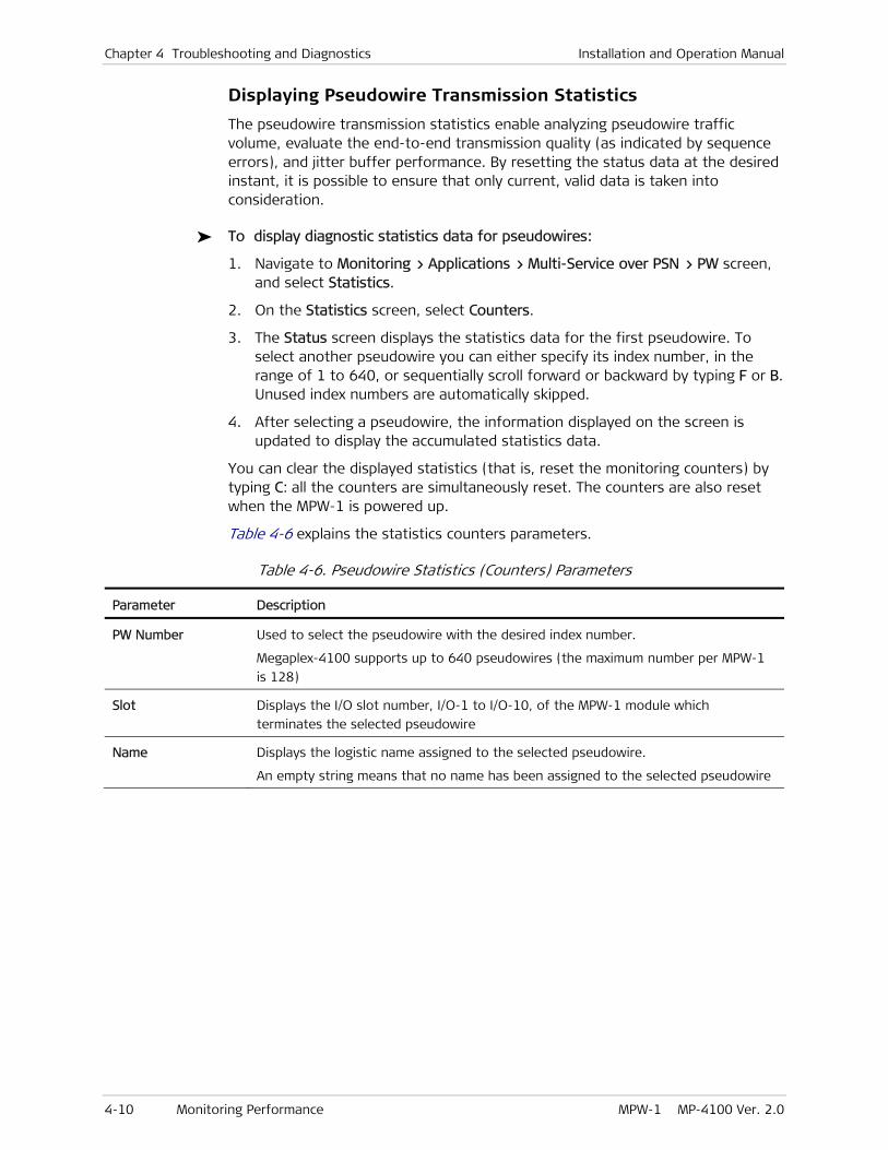
Chapter 4 Troubleshooting and Diagnostics Installation and Operation Manual
4-10 Monitoring Performance MPW-1 MP-4100 Ver. 2.0
Displaying Pseudowire Transmission Statistics
The pseudowire transmission statistics enable analyzing pseudowire traffic volume, evaluate the end-to-end transmission quality (as indicated by sequence errors), and jitter buffer performance. By resetting the status data at the desired instant, it is possible to ensure that only current, valid data is taken into consideration.
To display diagnostic statistics data for pseudowires:
1. Navigate to Monitoring > Applications > Multi-Service over PSN > PW screen, and select Statistics.
2. On the Statistics screen, select Counters.
3. The Status screen displays the statistics data for the first pseudowire. To select another pseudowire you can either specify its index number, in the range of 1 to 640, or sequentially scroll forward or backward by typing F or B. Unused index numbers are automatically skipped.
4. After selecting a pseudowire, the information displayed on the screen is updated to display the accumulated statistics data.
You can clear the displayed statistics (that is, reset the monitoring counters) by typing C: all the counters are simultaneously reset. The counters are also reset when the MPW-1 is powered up.
Table 4-6 explains the statistics counters parameters.
Table 4-6. Pseudowire Statistics (Counters) Parameters
Parameter Description
PW Number Used to select the pseudowire with the desired index number.
Megaplex-4100 supports up to 640 pseudowires (the maximum number per MPW-1
is 128)
Slot Displays the I/O slot number, I/O-1 to I/O-10, of the MPW-1 module which
terminates the selected pseudowire
Name Displays the logistic name assigned to the selected pseudowire.
An empty string means that no name has been assigned to the selected pseudowire

Installation and Operation Manual Chapter 4 Troubleshooting and Diagnostics
MPW-1 MP-4100 Ver. 2.0 Monitoring Performance 4-11
Parameter Description
Connectivity Status Displays the connectivity status of the selected pseudowire:
OK – the pseudowire carries traffic, and both the remote and the local pseudowire
endpoints receive Ethernet frames. However, there may be problems such as
sequence errors, underflows, overflows, etc., which may be displayed using the
Statistics function.
LOCAL FAIL – a failure has been detected at the local pseudowire endpoint.
REMOTE FAIL – a failure is reported by the remote pseudowire endpoint.
UNAVAILABLE – the pseudowire reports loss of connectivity (it did not receive
neither OAM, nor data packets for 10 seconds or more (OAM link then reports loss
of synchronization). This is often caused by network problems, or configuration
errors.
VALIDATION FAIL – the remote pseudowire endpoint replied to OAM packets, but
there is a configuration mismatch (the configuration parameters used at two
endpoints of the pseudowire are different).
TX Packets Total number of frames transmitted toward the PSN
RX Packets Total number of frames received from the PSN
Sequence Errors Total number of packets that did not arrive in time, as expected according to their
sequence number (either because they were lost in the network, or reordered). See
also Table 4-5
Jitter Buffer
Underflows
Total number of jitter buffer underflow events. See also Table 4-5
Jitter Buffer
Overflows
Total number of jitter buffer overflow events. See also Table 4-5
Monitoring Internal DS1 Port Status
When an internal DS1 port of the MPW-1 is included in a redundancy pair, the current redundancy status can be displayed.
To display the Int DS1 status:
1. Select Monitoring > Physical > I/O > I/O 2 (MPW1) > Int-DS1 > Status.
2. The screen displays the current function of the selected port within the Int DS1 pair:
Active The port is the active port (the port carrying the traffic).
Standby The port is in standby, and does not carry traffic.
Monitoring the Timing Source Status
Megaplex-4100 monitoring function enables displaying information regarding the current MPW-1 timing source (see details in the Megaplex-4100 Installation and Operation Manual).

Chapter 4 Troubleshooting and Diagnostics Installation and Operation Manual
4-12 Monitoring Performance MPW-1 MP-4100 Ver. 2.0
When a pseudowire is used as a Megaplex-4100 timing reference source, the timing source display includes information on the state of the pseudowire adaptive clock recovery mechanism.
To display the pseudowire adaptive clock recovery mechanism state:
1. Navigate to Monitoring > System > Timing.
2. You will see the Timing screen. The information displayed on the screen depends on the currently used timing source. Table 4-7 explains the information displayed when a pseudowire serves as the reference source.
Table 4-7. Timing Monitoring Parameters
Parameter Description
Active Clock Displays the type of timing reference source in use, Master of Fallback
Source Displays the selected nodal timing mode:
Internal – Timing locked to the MPW-1 internal oscillator
Rx Clock – Timing locked to the recovered receive clock signal of a user-selectable
interface, including a pseudowire configured as timing reference source
S Subsystem – Timing locked to the clock signal provided by the SDH/SONET
subsystem
Recovered – Timing locked to the recovered receive clock signal of a user-selected
pseudowire
Rx Clock Identifies the timing reference source in use: module type, its I/O slot number, and
the specific port. A pseudowire is identified as Recovered ID#X (PW#YYY), where X is
the index number of the pseudowire selected as recovered (adaptive) timing using
the System > Clock Source screen, and YYY is the pseudowire index number
Holdover Indicates whether the nodal timing subsystem is in the holdover state (Yes) or not
(No).
The nodal timing subsystem enters the holdover state when all the configured
sources (master and fallback) fail. In the holdover mode, the maintains the internal
reference frequency at the last value acquired before the failure. This situation
persists until at least one of the configured reference source returns to normal, and
thus is selected again as reference
Recovered Clock
Status
Displays the current status of the pseudowire adaptive clock recovey mechanism:
Free Run: indicates that the clock recovery mechanism is not locked to any clock.
Frequency Acquisition: indicates that the clock recovery mechanism is learning the
frequency of the selected reference.
Rapid Phase Lock: indicates that the clock recovery mechanism is in the training
process.
Fine Phase Lock: indicates that the clock recovery mechanism successfully completed
the training process., and is now locked. At this stage, the clock recovery mechanism
provides a stable clock of good quality.
----- : the adaptive clock recovery status is not relevant.

Installation and Operation Manual Chapter 4 Troubleshooting and Diagnostics
MPW-1 MP-4100 Ver. 2.0 Detecting Configuration Errors 4-13
4.2 Detecting Configuration Errors
Table 4-8 lists the specific configuration error messages that may generated by Megaplex-4100 for MPW-1 modules, and explains their interpretation. The messages are listed in ascending order of their codes.
For other sanity errors, refer to the Megaplex-4100 Installation and Operation Manual.
Table 4-8. MPW-1 Specific Error Messages
Code Syntax Type Meaning
2100 SAME IP FOR ROUTER IFACE &
D.GATEWAY
Error The same IP address has been defined for both the
default gateway and for one of the router interfaces. This
is not allowed.
Note however that this error may also appear because the
default IP addresses (0.0.0.0) have not yet been changed
2101 ROUTER IFACE IP>WAY NOT
SAME SUBNET
Error At least one of the IP addresses assigned to router
interfaces must be in the IP subnet of the MPW-1 router
default gateway
2103 OUT PW LABEL IS NOT UNIQUE Error This message, which is generated only after the specified
pseudowire is created, indicates that two or more
pseudowires directed to a given destination IP address
have the same source UDP port number (the check is
made irrespective of the pseudowire PSN type, UDP/IP or
MPLS/ETH). This is not allowed.
For UDP/IP PSNs, the UDP port is automatically assigned in
accordance with the pseudowire label value, therefore
you need to change the pseudowire labels to avoid
conflict. The assignment rules are as follows (see Chapter 3 for parameter descriptions):
• When the configured pseudowire Payload Format is V1
(proprietary format), the source UDP port is Out PW
Label + 1
• In all the other cases, the source UDP port value is
equal to the configured Out PW Label value
See also sanity error 2123
2104 IN PW LABEL IS NOT UNIQUE Error This message, which is generated only after the specified
pseudowire is created, indicates that two or more
pseudowires have the same source UDP port number (the
check is made irrespective of the pseudowire PSN type,
UDP/IP or MPLS/ETH). This is not allowed.
See sanity error 2103 for UDP port assignment rules

Chapter 4 Troubleshooting and Diagnostics Installation and Operation Manual
4-14 Detecting Configuration Errors MPW-1 MP-4100 Ver. 2.0
Code Syntax Type Meaning
2105 IP & NEXT HOP SAME FOR
STATIC ROUT
Error This message is generated after the specified static route
is updated, and indicates that the next hop IP address and
the destination IP address of the route are the same.
This is not allowed – the addresses must be different. If
the next hop IP address is not needed, leave the default
value, 0.0.0.0.
Note however that this error may also appear because the
default IP addresses (0.0.0.0) have not yet been changed
2106 STATIC ROUTE IP IS NOT
UNIQUE
Error This message, which is generated only after the specified
static route is updated, indicates that the route
destination IP address is already used in another static
route.
This is not allowed – only one static route may be defined
for any specific destination IP address.
Note however that this error may also appear because the
default IP addresses (0.0.0.0) have not yet been changed
2107 ROUTER IFACES CAN'T BE ON
SAME SUBNET
Error The IP addresses assigned to the router interfaces must
be in different IP subnets
2108 MORE THAN 16 PWS FOR
INTERNAL DS1
Error You are trying to connect too many pseudowires to the
same internal DS1 port (the maximum is 16 pseudowire
per port)
2110 ILLEGAL FAR END TYPE
CONFIGURATION
Error The pseudowire Far End Type parameter must match the
framing mode of the internal DS1 port supporting the
pseudowire:
• Framed mode: select E1, T1 ESF, or T1 SF
• Unframed mode: select UNFRAMED
2111 INTERNAL DS1 OF PW IS DOWN Error The internal DS1 port assigned to a pseudowire is
configured as Down. Change its administrative status to
Up
2112 PW ASSIGNMENT MISMATCH Warning When a pseudowire is created, it is necessary to assign it
timeslots on a specific internal DS1 port.
This message is generated only after the specified
pseudowire is created.
You can assign the timeslots during the configuration of
the pseudowire service parameters; in addition, connect
the same timeslots of the internal DS1 port to the
prescribed I/O or PDH port
2113 TOO MANY ROUTER
INTERFACES
Error You are trying to configure more than 6 router interfaces
on a MPW-1 module (MPW-1 supports a maximum of 6
router interfaces). Check and remove unused interfaces
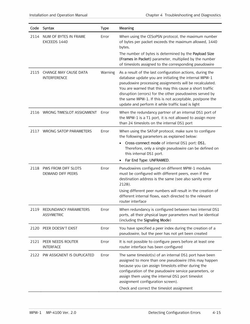
Installation and Operation Manual Chapter 4 Troubleshooting and Diagnostics
MPW-1 MP-4100 Ver. 2.0 Detecting Configuration Errors 4-15
Code Syntax Type Meaning
2114 NUM OF BYTES IN FRAME
EXCEEDS 1440
Error When using the CESoPSN protocol, the maximum number
of bytes per packet exceeds the maximum allowed, 1440
bytes.
The number of bytes is determined by the Payload Size
(Frames in Packet) parameter, multiplied by the number
of timeslots assigned to the corresponding pseudowire
2115 CHANGE MAY CAUSE DATA
INTERFERENCE
Warning As a result of the last configuration actions, during the
database update you are initiating the internal MPW-1
pseudowire processing assignments will be recalculated.
You are warned that this may this cause a short traffic
disruption (errors) for the other pseudowires served by
the same MPW-1. If this is not acceptable, postpone the
update and perform it while traffic load is light
2116 WRONG TIMESLOT ASSIGNMENT Error When the redundancy partner of an internal DS1 port of
the MPW-1 is a T1 port, it is not allowed to assign more
than 24 timeslots on the internal DS1 port
2117 WRONG SATOP PARAMETERS Error When using the SAToP protocol, make sure to configure
the following parameters as explained below:
• Cross-connect mode of internal DS1 port: DS1.
Therefore, only a single pseudowire can be defined on
this internal DS1 port.
• Far End Type: UNFRAMED.
2118 PWS FROM DIFF SLOTS
DEMAND DIFF PEERS
Error Pseudowires configured on different MPW-1 modules
must be configured with different peers, even if the
destination address is the same (see also sanity error
2128).
Using different peer numbers will result in the creation of
different internal flows, each directed to the relevant
router interface
2119 REDUNDANCY PARAMETERS
ASSYMETRIC
Error When redundancy is configured between two internal DS1
ports, all their physical layer parameters must be identical
(including the Signaling Mode)
2120 PEER DOESN'T EXIST Error You have specified a peer index during the creation of a
pseudowire, but the peer has not yet been created
2121 PEER NEEDS ROUTER
INTERFACE
Error It is not possible to configure peers before at least one
router interface has been configured
2122 PW ASSIGNENT IS DUPLICATED Error The same timeslot(s) of an internal DS1 port have been
assigned to more than one pseudowire (this may happen
because you can assign timeslots either during the
configuration of the pseudowire service parameters, or
assign them using the internal DS1 port timeslot
assignment configuration screen).
Check and correct the timeslot assignment

Chapter 4 Troubleshooting and Diagnostics Installation and Operation Manual
4-16 Handling Alarms MPW-1 MP-4100 Ver. 2.0
Code Syntax Type Meaning
2123 V1/V2 PW LABEL DUPLICATED Error After assigning a label to a pseudowire using payload
format V1, do not assign the next label in sequence to a
pseudowire using payload format V2 (skip that label).
See details given for sanity error 2103
2124 PEER NOT ATTACHED TO PW Error User has created a peer without attaching it to any
pseudowire
2125 SLOT/PORT OF R.IFACE IS NOT
CONNECTED
Error You must specify a valid I/O slot and port number to the
specified router interface
2126 WRONG FAR END TYPE
ASSIGNED TO RDN CH
Error When redundancy is configured between two internal DS1
ports, all their physical layer parameters must be identical
(including the Far End Type)
2127 PW FAR END TYPE PER SLOT IS
NOT EQUAL
Error When signaling is enabled on the internal DS1 port
attached to a pseudowire, the Far End Type for all the
pseudowires terminated on the corresponding MPW-1
must a framed mode (either E1 or T1)
2128 PEER PARAMETERS ARE
DUPLICATED
Error Different peers must not have the same destination IP
address and the same Next Hop IP address (at least one
of these parameters must be different). Therefore, if it
necessary for several pseudowires to reach the same IP
address, create separate router interfaces. See also sanity
error 2118
2129 CAN’T CARRY MIXED ETH & PW
TRAFFIC
Error An Ethernet port on an I/O module cannot be a member
of a flow that carries Ethernet traffic and at the same
time, be a member of another flow that carries
pseudowire traffic
2130 TS NOT ASSIGNED TO ANY PW Warning The specified MPW-1 internal DS1 port is connected to
local module ports, but no pseudowire has been assigned
timeslots on the same port (the reverse situation is
detected by sanity error 2122).
You must specify timeslots to be connected to the
internal DS1 port
2131 PW CREATED BUT NOT
ASSIGNED
Error A pseudowire has been created, but the attachment
circuit was not assigned timeslots
2132 PW CAN’T SERVE AS
RECOVERED CLK
Error A pseudowire using the HDLCoPSN protocol cannot serve
as recovered clock source
4.3 Handling Alarms
Table 4-9 lists the specific alarm messages that may generated by Megaplex-4100 for MPW-1 modules, and explains their interpretation. The messages are listed in ascending order of their codes. For other alarm messages, refer to the Megaplex-4100 Installation and Operation Manual.

Installation and Operation Manual Chapter 4 Troubleshooting and Diagnostics
MPW-1 MP-4100 Ver. 2.0 Handling Alarms 4-17
Table 4-9. MPW-1 Specific Alarms
Code Message Type Default
Severity Interpretation
028 HARDWARE/SOFTWARE
MISMATCH
SL:CH Major It is not allowed to configure the clock quality of
the recovered clock to Stratum 1 or Stratum 2 for
your MPW-1 version. Contact RAD Marketing
Department for details
1201 PW OAM OUT OF SYNC PW Major The OAM signaling mechanism (used to check
connectivity) detected loss of connectivity
1202 PW OAM CONFIGURATION
MISMATCH
PW Major Packet discarded due to mismatch in TDMoIP
frame format between the received packet and
the pseudowire configuration
1204 PW HW LACK OF TX BUFFERS PW Major Packet discarded due to mismatch between
received packet length and pseudowire
configuration
1205 PW LOCAL FAIL PW Major Ethernet frames are not received by the local
pseudowire on the specified connection
1206 PW LINK FAIL IN REMOTE UNIT PW Major The remote unit reports the reception of a packet
with Local Fail indication (L-bit set)
1207 PW REMOTE FAIL (RDI) PW Major The remote unit reports the reception of a packet
with Remote Fail indication (R-bit set).
1209 PW RX FRAME LENGTH
MISMATCH
PW Major Packet discarded due to mismatch between
received Ethernet packet length and pseudowire
configuration
1210 PW SEQUENCE ERR INSIDE
WINDOW
PW Event TDMoIP/MPLS packet sequence number error
found within the window
1212 PW SEQUENCE ERR OUTSIDE
WINDOW
PW Event TDMoIP/MPLS packet sequence number error
found outside the tracking window
1214 PW JITTER BUFFER UNDERRUN PW Event Underrun has occurred in the jitter buffer of the
corresponding pseudowire
1216 PW JITTER BUFFER OVERRUN PW Event Overrun has occurred in the jitter buffer of the
corresponding pseudowire
1220 PW RX TDMOIP VERSION
MISMATCH
PW Major Mismatch between local and remote pseudowire
TDMoIP versions
1323 RX MISS ORDERED FRAMES
DISCARDED
PW Event Packets discarded due to missordering
2029 SFP NOT EXIST SL:CH Major The SFP is not Installed in its socket (this alarm
will not appear when the user disables the
corresponding LAN port)
2060 LAN NOT CONNECTED SL:CH Major The LAN interface of the MPW-1 is not connected
to an active Ethernet LAN (this alarm will not
appear when the user disables the corresponding
LAN port)

Chapter 4 Troubleshooting and Diagnostics Installation and Operation Manual
4-18 Troubleshooting MPW-1 MP-4100 Ver. 2.0
4.4 Troubleshooting
In case a problem occurs with one of the pseudowires carried by the MPW-1 module, check the displayed alarm messages and refer to Section 4.3 and to the Megaplex-4100 Installation and Operation Manual for their interpretation.
If the problem is detected the first time the module is put into operation, perform the following preliminary checks before proceeding:
• Check for proper module installation and correct cable connections, in accordance with the system installation plan.
• Check the module configuration parameters in accordance with the specific application requirements, as provided by the system administrator.
• If the Megaplex-4100 nodal clock is to be locked to the clock recovered from one of the pseudowires carried by the MPW-1 module, make sure a suitable fallback clock source is configured and provides a good clock signal.
After collecting all the relevant information, perform the actions listed below until the problem is corrected:
• Make sure that no test has been activated on the corresponding MPW-1 internal DS1 port. Use the Megaplex-4100 management system to find the active test or loopback, and deactivate it.
• Activate the local loopback on the corresponding port timeslots that carry the corresponding pseudowire. While the loop is connected, the user’s equipment served by pseudowires configured on the corresponding port should receive its own signal; if not, the problem is external. Check cable connections, and any transmission equipment providing the link to the user’s equipment.
• You can rapidly check the link to the remote unit by activating, at the remote unit, the remote loopback on the corresponding timeslots of the remote internal DS1 port. If the link operates OK, the local user’s equipment served by pseudowires configured on the corresponding port should receive its own signal.
If the test fails, there is a problem with the transmission through the network, or with the MPW-1 modules:
Using the ping test to check IP connectivity to the destination IP address of the relevant pseudowires. If ping fails, the problem is in the network
Repeat the test after carefully checking all the configuration parameters of the module and its ports. If the problem persists, replace the module and check again.
Note
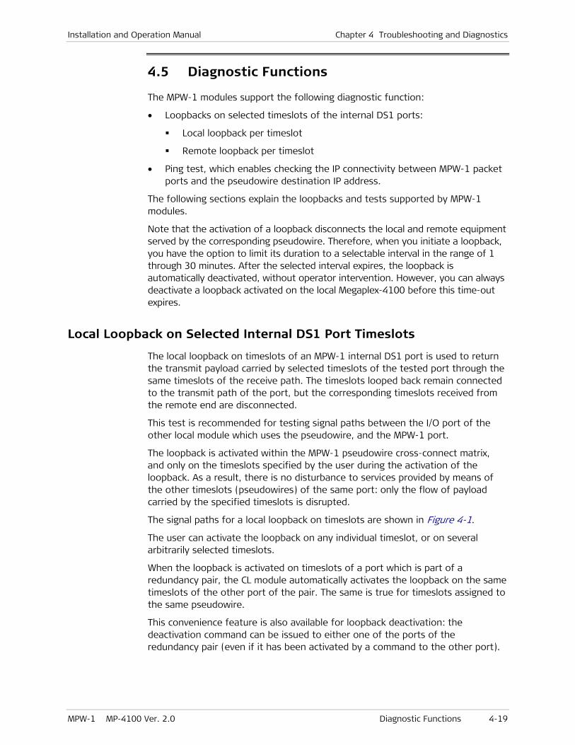
Installation and Operation Manual Chapter 4 Troubleshooting and Diagnostics
MPW-1 MP-4100 Ver. 2.0 Diagnostic Functions 4-19
4.5 Diagnostic Functions
The MPW-1 modules support the following diagnostic function:
• Loopbacks on selected timeslots of the internal DS1 ports:
Local loopback per timeslot
Remote loopback per timeslot
• Ping test, which enables checking the IP connectivity between MPW-1 packet ports and the pseudowire destination IP address.
The following sections explain the loopbacks and tests supported by MPW-1 modules.
Note that the activation of a loopback disconnects the local and remote equipment served by the corresponding pseudowire. Therefore, when you initiate a loopback, you have the option to limit its duration to a selectable interval in the range of 1 through 30 minutes. After the selected interval expires, the loopback is automatically deactivated, without operator intervention. However, you can always deactivate a loopback activated on the local Megaplex-4100 before this time-out expires.
Local Loopback on Selected Internal DS1 Port Timeslots
The local loopback on timeslots of an MPW-1 internal DS1 port is used to return the transmit payload carried by selected timeslots of the tested port through the same timeslots of the receive path. The timeslots looped back remain connected to the transmit path of the port, but the corresponding timeslots received from the remote end are disconnected.
This test is recommended for testing signal paths between the I/O port of the other local module which uses the pseudowire, and the MPW-1 port.
The loopback is activated within the MPW-1 pseudowire cross-connect matrix, and only on the timeslots specified by the user during the activation of the loopback. As a result, there is no disturbance to services provided by means of the other timeslots (pseudowires) of the same port: only the flow of payload carried by the specified timeslots is disrupted.
The signal paths for a local loopback on timeslots are shown in Figure 4-1.
The user can activate the loopback on any individual timeslot, or on several arbitrarily selected timeslots.
When the loopback is activated on timeslots of a port which is part of a redundancy pair, the CL module automatically activates the loopback on the same timeslots of the other port of the pair. The same is true for timeslots assigned to the same pseudowire.
This convenience feature is also available for loopback deactivation: the deactivation command can be issued to either one of the ports of the redundancy pair (even if it has been activated by a command to the other port).
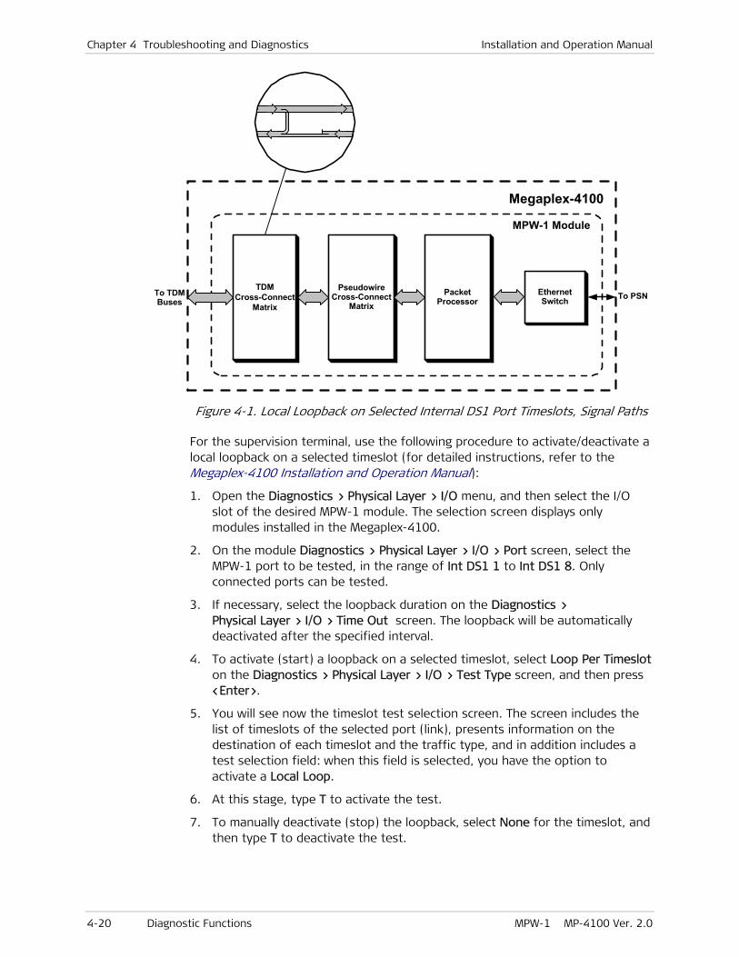
Chapter 4 Troubleshooting and Diagnostics Installation and Operation Manual
4-20 Diagnostic Functions MPW-1 MP-4100 Ver. 2.0
Megaplex-4100
PseudowireCross-Connect
Matrix
MPW-1 Module
TDMCross-Connect
Matrix
PacketProcessor
EthernetSwitch To PSNTo TDM
Buses
Figure 4-1. Local Loopback on Selected Internal DS1 Port Timeslots, Signal Paths
For the supervision terminal, use the following procedure to activate/deactivate a local loopback on a selected timeslot (for detailed instructions, refer to the Megaplex-4100 Installation and Operation Manual):
1. Open the Diagnostics > Physical Layer > I/O menu, and then select the I/O slot of the desired MPW-1 module. The selection screen displays only modules installed in the Megaplex-4100.
2. On the module Diagnostics > Physical Layer > I/O > Port screen, select the MPW-1 port to be tested, in the range of Int DS1 1 to Int DS1 8. Only connected ports can be tested.
3. If necessary, select the loopback duration on the Diagnostics > Physical Layer > I/O > Time Out screen. The loopback will be automatically deactivated after the specified interval.
4. To activate (start) a loopback on a selected timeslot, select Loop Per Timeslot on the Diagnostics > Physical Layer > I/O > Test Type screen, and then press <Enter>.
5. You will see now the timeslot test selection screen. The screen includes the list of timeslots of the selected port (link), presents information on the destination of each timeslot and the traffic type, and in addition includes a test selection field: when this field is selected, you have the option to activate a Local Loop.
6. At this stage, type T to activate the test.
7. To manually deactivate (stop) the loopback, select None for the timeslot, and then type T to deactivate the test.

Installation and Operation Manual Chapter 4 Troubleshooting and Diagnostics
MPW-1 MP-4100 Ver. 2.0 Diagnostic Functions 4-21
Remote Loopback on Selected Internal DS1 Port Timeslots
The signal paths for a remote loopback on timeslots are shown in Figure 4-2.
Megaplex-4100
PseudowireCross-Connect
Matrix
MPW-1 Module
TDMCross-Connect
Matrix
PacketProcessor
EthernetSwitch To PSNTo TDM
Buses
Figure 4-2. Remote Loopback on Selected Internal DS1 Port Timeslots, Signal Paths
The remote loopback on timeslots of an MPW-1 port is used to return the receive payload carried by selected timeslots of the tested port through the same timeslots of the transmit path. The corresponding timeslots received from the local equipment are disconnected.
This test is recommended for testing signal paths from a remote equipment unit, through a selected pseudowire served by the corresponding MPW-1 port.
The loopback is activated within the MPW-1 cross-connect matrix, and only on the timeslots specified by the user during the activation of the loopback. As a result, there is no disturbance to services provided by means of the other timeslots (pseudowires) of the same port: only the flow of payload carried by the specified timeslots is disrupted.
For the supervision terminal, use the following procedure to activate/deactivate a remote loopback on a selected timeslot (for detailed instructions, refer to the Megaplex-4100 Installation and Operation Manual):
1. Open the Diagnostics > Physical Layer > I/O menu, and then select the I/O slot of the desired MPW-1 module. The selection screen displays only modules installed in the Megaplex-4100.
2. On the module Diagnostics > Physical Layer > I/O > Port screen, select the MPW-1 port to be tested, in the range of Int DS1 1 to Int DS1 8. Only connected ports can be tested.
3. If necessary, select the loopback duration on the Diagnostics > Physical Layer > I/O > Time Out screen. The loopback will be automatically deactivated after the specified interval.

Chapter 4 Troubleshooting and Diagnostics Installation and Operation Manual
4-22 Diagnostic Functions MPW-1 MP-4100 Ver. 2.0
4. To activate (start) a loopback on a selected timeslot, select Loop Per Timeslot on the Diagnostics > Physical Layer > I/O > Test Type screen, and then press <Enter>.
5. You will see now the timeslot test selection screen. The screen includes the list of timeslots of the selected port (link), presents information on the destination of each timeslot and the traffic type, and in addition includes a test selection field: when this field is selected, you have the option to activate a Remote Loop.
6. At this stage, type T to activate the test.
7. To deactivate (stop) the loopback, select None for the timeslot, and then type T to deactivate the test.
The other features related to loopback activation/deactivation described above for the local loopback on timeslots are also applicable to the remote loopback.
Ping Test
MPW-1 modules installed in Megaplex-4100 can use the ping function, to check IP connectivity between a MPW-1 packet port and the desired destination IP address (that is, to a pseudowire peer). The user can select the destination IP address and configure the number of ping packets sent. The port used to send the ping packets is automatically selected, in accordance with the following criteria:
1. If the destination IP address is within the host IP subnet of the CL module, the ping packets are sent by the CL module, and therefore use its IP address as the source address.
2. If the destination IP address is not within the CL module subnet, but is within the subnet of one of the router interfaces, the ping packets are sent by the MPW-1 module associated with that router interface.
3. If the destination IP address is neither within the CL module subnet, nor within a router interface, the ping packets are sent by the CL module using the configured default gateway.
For the supervision terminal, use the following procedure to send pings to a selected peer (for detailed instructions, refer to the Megaplex-4100 Installation and Operation Manual):
1. Open the Diagnostics menu, and then select Ping Test.
2. On the Ping Test screen, select the following parameters:
The desired destination IP address
The number of ping packets (up to 50) to be sent. Pinging will be automatically stopped after sending the specified number of ping packets.
3. To start ping sending, select Send Ping, and then press <Enter>.
4. The prompt area at the bottom of the screen starts displaying the results of each ping packet. After the selected number of packets, you will see the test summary, which indicates the number of packets sent and received, and the number of lost packets (packets not answered before the standard time-out interval expires).

Installation and Operation Manual Chapter 4 Troubleshooting and Diagnostics
MPW-1 MP-4100 Ver. 2.0 Technical Support 4-23
4.6 Technical Support
Technical support for this product can be obtained from the local distributor from whom it was purchased.
For further information, please contact the RAD distributor nearest you or one of RAD's offices worldwide. This information can be found at www.rad.com (offices – About RAD > Worldwide Offices; distributors – Where to Buy > End Users).

Chapter 4 Troubleshooting and Diagnostics Installation and Operation Manual
4-24 Technical Support MPW-1 MP-4100 Ver. 2.0

24 Raoul Wallenberg Street, Tel Aviv 69719, Israel
Tel: +972-3-6458181, Fax +972-3-6483331, +972-3-6498250
E-mail: [email protected], Web site: http://www.rad.com
Customer Response Form
RAD Data Communications would like your help in improving its product documentation. Please complete and return this form by mail or by fax or send us an e-mail with your comments.
Thank you for your assistance!
Manual Name: MPW-1 MP-4100 Ver. 2.0
Publication Number: 464-202-12/08
Please grade the manual according to the following factors:
Excellent Good Fair Poor Very Poor
Installation instructions � � � � �
Operating instructions � � � � �
Manual organization � � � � �
Illustrations � � � � �
The manual as a whole � � � � �
What did you like about the manual?


Error Report
Type of error(s) or problem(s):
� Incompatibility with product
� Difficulty in understanding text
� Regulatory information (Safety, Compliance, Warnings, etc.)
� Difficulty in finding needed information
� Missing information
� Illogical flow of information
� Style (spelling, grammar, references, etc.)
� Appearance
� Other
Please list the exact page numbers with the error(s), detail the errors you found (information missing, unclear or inadequately explained, etc.) and attach the page to your fax, if necessary.
Please add any comments or suggestions you may have.
You are: � Distributor
� End user
� VAR
� Other
Who is your distributor?
Your name and company:
Job title:
Address:
Direct telephone number and extension:
Fax number:
E-mail:


Publication No. 464-202-12/08
Order this publication by Catalog No. 803835
International Headquarters 24 Raoul Wallenberg Street
Tel Aviv 69719, Israel
Tel. 972-3-6458181
Fax 972-3-6498250, 6474436
E-mail [email protected]
North America Headquarters 900 Corporate Drive
Mahwah, NJ 07430, USA
Tel. 201-5291100 Toll free 1-800-4447234
Fax 201-5295777
E-mail [email protected]
www.rad.com The Access Company


