53
Revised 4/4/2013 1 IMPORTANT : OPERATOR AND PARTS MANUAL 1000 Series Fertilizer Applicator

Revised 4/4/2013 1
IMPORTANT:
OPERATOR AND PARTS MANUAL
1000 Series Fertilizer Applicator

Revised 4/4/2013 2
Bestway
1000 Series Fertilizer Applicator
Introduction
TO THE OWNER Thank you for purchasing a Bestway 1000 Series Fertilizer Applicator. This machine is designed to be a heavy-duty unit for liquid fertilizer application.
This Fertilizer Applicator features: • Cat III 3 point hitch • Ground driven pump, or a centrifugal pump with Raven controller options • 7” x 7" mainframe tubing • Designed for mounting of many types of coulters
Bestway Fertilizer Applicators have been designed to provide many years of profitable and dependable service. To assure maximum performance of your Fertilizer Applicator, it is mandatory that you thoroughly study the operator's manual and follow its recommendations. Proper operation and maintenance are essential for safety, to maintain performance, and to maximize the life of the Fertilizer Applicator.
It is the owner's responsibility to: Operate and maintain this Fertilizer Applicator in a safe manner and in accordance with all applicable local, state, and federal codes and/or laws; and in compliance with labeling instructions furnished by the supplier of the chemical being used.
Make sure each and every operator has read the operator's manual and thoroughly understands safe and correct operating procedures.
Make sure unauthorized people do not operate or are not in the vicinity of the Fertilizer Applicator while it is in operation.
Maintain the Fertilizer Applicator in accordance with the maintenance schedule in this manual. Furthermore, as additional technology becomes available, the owner is responsible for improving the safety and reliability of the system.
Fulfill all warranty obligations so as not to void the warranties. Verify the unit is warranty registered prior to making any warranty claims. The warranty section at the back of this manual outlines the warranty policy of Bestway.
Abuse or modifications to the Fertilizer Applicator that change the performance other than original factory specifications void the warranty.
Bestway reserves the right to make product improvements to the equipment at any time. It shall not be obligated to make such changes to machines already in service.
*The owner, manager and/or operator is responsible for safe, accurate operation and maintenance of the Bestway 1000 Series Fertilizer Applicator.

Revised 4/4/2013 3
Bestway
Table of Contents
Table of Contents
Safety Instructions - Section A ...........................................................................................................5 •Safety First .......................................................................................................................................... 6 •Safety Instruction for Operation ........................................................................................................ 7 •Safety Decals ..................................................................................................................................... 9
Operation Instructions - Section B .................................................................................................. 11 •Inspect Unit ....................................................................................................................................... 12 •System Overview ............................................................................................................................. 12 •Hitch ................................................................................................................................................. 12 •Hydraulics ......................................................................................................................................... 13 •Light System ..................................................................................................................................... 13 •Setting the Toolbar Depth ................................................................................................................14 •Centrifugal Pump...............................................................................................................................15 - Rate Controller ..................................................................................................................15 •Ground Drive Pump ..........................................................................................................................16 •Plumbing Orifices ..............................................................................................................................17 •Nozzle Selection ...............................................................................................................................18 •Spray Ball Monitors ......................................................................................................................... 20
Maintenance & Service - Section C ................................................................................................ 23 •Structure ........................................................................................................................................... 24 •Hydraulics ........................................................................................................................................ 24 •Electrical and Lighting System ....................................................................................................... 24 •Lubrication ....................................................................................................................................... 25 •Preventative Maintenance .............................................................................................................. 26 - Wheel and Coulter Bearings .............................................................................................26 - Cylinder Rods .................................................................................................................... 26 - Pre-Season Startup Check ...............................................................................................26 - Post-Season Storage ........................................................................................................26 •Bolt Torque Data .............................................................................................................................27
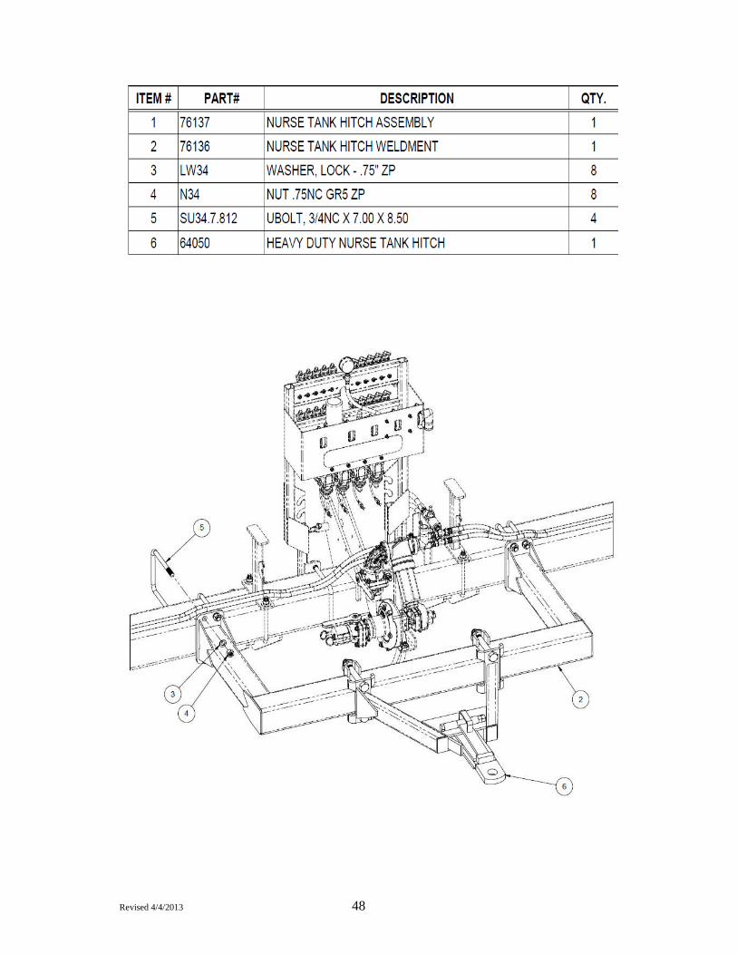
Parts & Schematics - Section D ......................................................................................................29 •Tool Bar Assembly ............................................................................................................................ 30 •Hydraulic Driven Pump Assembly................................................................................................... 36 •Ground Driven Pump Assembly...................................................................................................... 38 •Gauge Wheel Assembly .................................................................................................................. 39 •Gauge Wheel Hub ........................................................................................................................... 40 •Parking Stand ................................................................................................................................... 41 •Flow Meter Plumbing For Ground Drive Systems ......................................................................... 42 •Flow Meter Plumbing For Hyd. Drive Systems .............................................................................. 44 •Hitch Option ...................................................................................................................................... 48
Warranty & Serial Information - Section E .......................................... ..........................................50 •Serial and Model Number Location .................................................... ..........................................51 •Warranty ...............................................................................................…………………………… 52

Revised 4/4/2013 4
Bestway
Table of Contents
Manufacturer's statement: for technical reasons Bestway Inc. reserves the right to modify machinery design and specifications provided herein without any preliminary notice. Information provided herein is of descriptive nature. Performance quality may depend on soil fertility, applied agricultural techniques, weather conditions and other factors.
NOTES:

Revised 4/4/2013 5
Safety Instruction Section A
Revised 4/4/2013 6
Bestway
Safety First
Safety Instructions - Section A
Accidents can be prevented by recognizing the causes or hazards before an accident occurs ... and doing something about them.
Regardless of the care used in the design and construction of this equipment, there are some areas that cannot be completely safeguarded without interfering with the accessibility and efficiency of operation.
TAKE NOTE! THIS SAFETY ALERT SYMBOL FOUND THROUGHOUT THIS MANUAL IS USED TO CALL YOUR ATTENTION TO INSTRUCTIONS INVOLVING YOUR PERSONAL SAFETY AND THE SAFETY OF OTHERES. FAILURE TO FOLLOW THESE INSTRUCTIONS CAN RESULT IN INJURY OR DEATH.
In this manual and on labels used on the machine the words DANGER, WARNING, and CAUTION are used to indicate the following: DANGER:
WARNING:
CAUTION:
Indicates an imminently hazardous situation that, if not avoided, will result in death or serious injury.
Indicates a potentially hazardous situation that if not avoided, could result in death or serious injury.
Indicates a potentially hazardous situation that, if not avoided, may result in minor or moderate injury.
THIS MESSAGE ALERT SYMBOL IDENTIFIES INFORMATION THAT MUST BE HEEDED FOR PROPER OPERATION OF EQUIPMENT AND TO PREVENT DAMAGE OR DETERIORATION OF THE EQUIPMENT.
In this manual the words IMPORTANT and NOTE are used to indicate the following:
IMPORTANT: Highlights information that must be heeded.
NOTE: A reminder of other related information that needs to be considered.

Revised 4/4/2013 7
Bestway
Safety Instructions - Section A
Safety Instructions for Operation
1. DO NOT ALLOW ANYONE TO OPERATE FERTILIZER APPLICATOR UNTIL HE OR SHE HAS READ THIS MANUAL AND IS COMPLETELY FAMILIAR WITH ALL SAFETY AND OPERATION PROCEDURES.
Observe the IMPORTANT SAFETY INSTRUCTIONS listed below at all times. THE BEST KIND OF SAFETY IS A CAREFUL OPERATOR.
Always wear protective clothing, goggles, respirator and gloves when handling chemicals.
Always wear protective clothing, goggles, respirator and gloves when handling chemicals.
Observe all federal and state EPA regulations and all local, state, provincial and federal codes and / or laws regarding licensing, handling, storage, transportation, application and waste disposal of chemicals.
2. If any safety device on the Fertilizer Applicator itself is not functioning properly, DO NOT use the
Fertilizer Applicator. Remove it from service until it has been properly repaired by a qualified service technician.
3. Do not allow the following people to operate or repair this equipment:
• Children • Irresponsible persons • People under the influence of alcohol, medications or other drugs that can cause drowsiness or
impaired judgment. • Persons unfamiliar with equipment or people who are careless or unfamiliar with safe operating
procedures. People who are allergic to any of the chemicals used must never be allowed in or near the Fertilizer Applicator.
4. Always park the Fertilizer Applicator on a level surface, and lock the tractor brakes, or block the tires, before making adjustments or repairs.
5. Before operating this equipment, thoroughly inspect the unit to ensure it is in good working order.
6. Do not operate this unit if any defect or malfunction exists. Pay particular attention to safety features such as safety chains.
7. Verify that the Fertilizer Applicator is securely hitched to the tractor.
8. Shut off tractor and put in park, engage the parking brake, and disengage hydraulic power before servicing or making adjustments to the toolbar and other equipment.
9. Keep all guards in place during operation. Keep all safety decals clean and legible. Contact Bestway Inc. for replacement decals if they are illegible.
10. Lower implement to ground when storing or leaving machine unattended.
WARNING
WARNING
CAUTION
DANGER
Revised 4/4/2013 8
Bestway
Safety Instructions - Section A
11. Equipment is to be operated by qualified personnel only. A full understanding of the operation, maintenance, and safety requirements is mandatory before use.
12. Follow all tractor operating procedures and safety information.
13. Before operating the applicator toolbar, be sure the cylinders and hydraulic hoses are fully charged with oil. If air is still in the system when operating, the 1000 series toolbar may fold, unfold, lift and lower rapidly and erratically. Ensure no one is in the area of the tractor and tool bar when folding and unfolding. Serious injury or death may occur if the tool bar strikes personnel.
14. Absolutely no riders on the implement. A fall will cause severe injury and possible death.
15. Hydraulic oil escaping under pressure has sufficient force to penetrate the skin, causing personal injury or death. Depending on the type of tractor hydraulic system, relieve pressure when attaching or disconnecting the implement by either placing the corresponding hydraulic lever in float position and shutting the tractor off, or shutting the tractor off and moving the hydraulic lever both directions. Be sure all hydraulic connections are tight and hoses are not damaged before operating the machinery. Escaping hydraulic oil from a small hole can be almost invisible. Do not use your hands to search for a hydraulic leak. Use a piece of cardboard or wood to look for leak spray. IF INJURED BY ESCAPING HYDRAULIC OIL, SEE A DOCTOR AT ONCE. SERIOUS REACTION AND INFECTION CAN DEVELOP IF PROPER MEDICAL TREATMENT IS NOT ADMINISTERED IMMEDIATELY.
16. Be extremely careful when working around unshielded coulter and disc blades. Serious injury may occur if contact is made with sharp blades.
17. Stopping distance increases as the square of the speed. For example: It will take twice as much distance to stop a unit traveling 15 mph as one going 10 mph; and four times the distance at 20 mph (more than eight times the distance at 25 mph)! Road surface will influence stopping distance. Dry pavement is usually considerably better than gravel road. Materials (such as ice, snow, water, oil or mud) on the surface can greatly increase stopping distance. Road slope has a significant impact on stopping distance and can greatly magnify the other factors mentioned above. Under some downhill conditions stopping can be very difficult or impossible.
18. Do not replace components or parts with those other than genuine Bestway Factory Service Parts. To do so may reduce the effectiveness of safety features or decrease the accuracy of the unit.
19. Read the Operation Instructions section of this manual for further necessary information relating to the safe operation of the applicator.
WARNING
Certain chemicals can be very corrosive and may oxidize steel over a period of time. This weakens steel parts and can cause failure to perform as intended, resulting in possible safety hazards. Periodically check all safety shields and structural members for corrosion. Replace or repair anything that could cause a potential safety hazard.

Revised 4/4/2013 9
2. Bestway
Safety Decals on a Bestway 1000 Series Fertilizer Applicator
Safety Instructions - Section A
3. 4. 5.
DEC-HAZ02 DEC-2
DEC-MT4163
DEC-HAZ01
DEC-MT4163
SW001
60962 SW900

Revised 4/4/2013 10
Bestway
NOTES:
Safety Instructions - Section A

Revised 4/4/2013 11
Operation Instructions Section B
Revised 4/4/2013 12
Bestway
Inspect Unit
IMPORTANT
System Overview
Operation Instructions - Section B
Check machine thoroughly for screws, bolts, fittings, etc., which may have come loose during transport or operation.
The Bestway Model 1000 Fertilizer Applicator consists of the following components: Hitch, 3 point Category III Fold Hydraulics - Operating Setting Toolbar Depth
Lighting and Marking Systems
Ground Drive Pump, or Centrifugal Pump and Controller Plumbing Coulters with Liquid Injectors or Knives Spray Ball Monitors
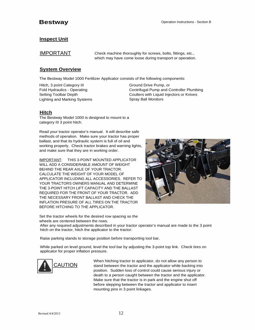
Hitch The Bestway Model 1000 is designed to mount to a category III 3 point hitch. Read your tractor operator’s manual. It will describe safe methods of operation. Make sure your tractor has proper ballast, and that its hydraulic system is full of oil and working properly. Check tractor brakes and warning lights, and make sure that they are in working order. IMPORTANT: THIS 3-POINT MOUNTED APPLICATOR WILL ADD A CONSIDERABLE AMOUNT OF WEIGHT BEHIND THE REAR AXLE OF YOUR TRACTOR. CALCULATE THE WEIGHT OF YOUR MODEL OF APPLICATOR INCLUDING ALL ACCESSORIES. REFER TO YOUR TRACTORS OWNERS MANUAL AND DETERMINE THE 3-POINT HITCH LIFT CAPACITY AND THE BALLAST REQUIRED FOR THE FRONT OF YOUR TRACTOR. ADD THE NECESSARY FRONT BALLAST AND CHECK THE INFLATION PRESURE OF ALL TIRES ON THE TRACTOR BEFORE HITCHING TO THE APPLICATOR. Set the tractor wheels for the desired row spacing so the wheels are centered between the rows.
After any required adjustments described in your tractor operator’s manual are made to the 3 point hitch on the tractor, hitch the applicator to the tractor. Raise parking stands to storage position before transporting tool bar. While parked on level ground, level the tool bar by adjusting the 3-point top link. Check tires on applicator for proper inflation pressure.
CAUTION
When hitching tractor to applicator, do not allow any person to stand between the tractor and the applicator while backing into position. Sudden loss of control could cause serious injury or death to a person caught between the tractor and the applicator. Make sure that the tractor is in park and the engine shut off before stepping between the tractor and applicator to insert mounting pins in 3 point linkages.

Revised 4/4/2013 13
Bestway
Hydraulics
Operation Instructions - Section B
Tractor Requirements • Closed center hydraulic systems are recommended if the applicator is equipped with a
hydraulic driven solution pump. Refer to the pump operation instructions (included with applicator) to make sure the tractor hydraulic system has been adjusted to match the pressure and flow requirements. FAILURE TO REGULATE THE OIL FLOW TO THE PUMP WILL CAUSE MOTOR DAMAGE! • If the applicator model has folding wings, the remote valve on the tractor that the fold
cylinders are connected to should be turned down as low as possible so the that the wings fold at a safe speed. • Hydraulic System pressure: 3,000 psi, max.
Start-Up Procedures 1. A copy of this page should be kept readily available with the machine. 2. The hoses for connection to the tractor valves are equipped with color coded hand grips.
Green and Yellow are fold and unfold functions. Red is hydraulic pressure to pump. Black is hydraulic return from pump.
3. Connect hydraulic hoses and 7-pin electrical connector before starting up. If wings move too slowly, increase the hydraulic flow to the hydraulic remote connected to the green and yellow coded hydraulic hoses.
Light System
Connect the 7-pin male connector to the tractor's 7-pin female connector at the rear of the tractor. The connector for the applicator is located near the hitch. If the tractor is not equipped with such a connector, see your tractor dealer.

Revised 4/4/2013 14
Bestway
Setting the Toolbar Depth
Operation Instructions - Section B
1. To adjust toolbar height there is a series of holes in the gauge wheel mount bracket. Align the
adjustment holes that obtain the desired operating height for the gauge wheel and insert the bolt provided in the adjustment hole. Set all gauge wheels the same height.
2. Check depth while operating in the field. 3. If the applicator is equipped with ground drive, adjust ground drive to have only enough down
pressure to prevent tire slippage. Excessive tire down pressure will increase wear and may damage the unit. Adjust down pressure by pinning the gauge adjustment bracket in a different location.
Revised 4/4/2013 15
6. 7. 8. Bestway Operation Instructions - Section B
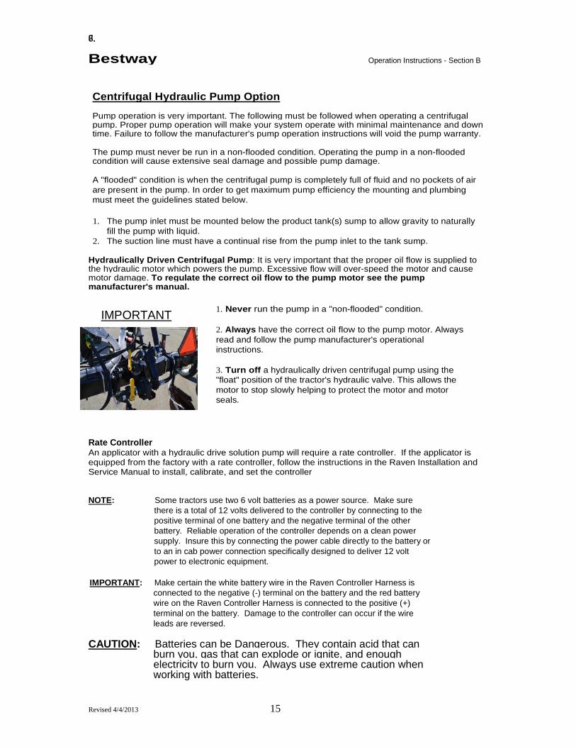
Centrifugal Hydraulic Pump Option Pump operation is very important. The following must be followed when operating a centrifugal pump. Proper pump operation will make your system operate with minimal maintenance and down time. Failure to follow the manufacturer's pump operation instructions will void the pump warranty. The pump must never be run in a non-flooded condition. Operating the pump in a non-flooded condition will cause extensive seal damage and possible pump damage. A "flooded" condition is when the centrifugal pump is completely full of fluid and no pockets of air are present in the pump. In order to get maximum pump efficiency the mounting and plumbing must meet the guidelines stated below.
1. The pump inlet must be mounted below the product tank(s) sump to allow gravity to naturally
fill the pump with liquid. 2. The suction line must have a continual rise from the pump inlet to the tank sump.
Hydraulically Driven Centrifugal Pump : It is very important that the proper oil flow is supplied to the hydraulic motor which powers the pump. Excessive flow will over-speed the motor and cause motor damage. To regulate the correct oil flow to the pump motor see the pump manufacturer's manual.
1. Never run the pump in a "non-flooded" condition. 2. Always have the correct oil flow to the pump motor. Always read and follow the pump manufacturer's operational instructions. 3. Turn off a hydraulically driven centrifugal pump using the "float" position of the tractor's hydraulic valve. This allows the motor to stop slowly helping to protect the motor and motor seals.
Rate Controller An applicator with a hydraulic drive solution pump will require a rate controller. If the applicator is equipped from the factory with a rate controller, follow the instructions in the Raven Installation and Service Manual to install, calibrate, and set the controller
NOTE: Some tractors use two 6 volt batteries as a power source. Make sure there is a total of 12 volts delivered to the controller by connecting to the positive terminal of one battery and the negative terminal of the other battery. Reliable operation of the controller depends on a clean power supply. Insure this by connecting the power cable directly to the battery or to an in cab power connection specifically designed to deliver 12 volt power to electronic equipment.
IMPORTANT: Make certain the white battery wire in the Raven Controller Harness is connected to the negative (-) terminal on the battery and the red battery wire on the Raven Controller Harness is connected to the positive (+) terminal on the battery. Damage to the controller can occur if the wire leads are reversed.
CAUTION: Batteries can be Dangerous. They contain acid that can burn you, gas that can explode or ignite, and enough electricity to burn you. Always use extreme caution when working with batteries.
IMPORTANT

Revised 4/4/2013 16
Bestway Ground Drive Pump Option If the applicator is equipped with a John Blue ground drive pump, refer to the pump operator’s manual included from the factory with the Bestway toolbar.
Adjust ground drive wheel to have only enough down pressure to prevent tire slippage. Excessive tire down pressure will increase wear and may damage the unit. Adjust down pressure by pinning the gauge adjustment bracket in a different location.
Operation Instructions - Section B
NOTE
To set the ground drive pump; the tire loaded radius, number of wheel sprocket teeth and drive sprocket teeth is necessary. The ground drive wheel has a 50 tooth sprocket driving to an 18 tooth sprocket on the jack shaft. Then a 24 tooth sprocket on the jack shaft drives an 18 tooth sprocket on the pump. With this sprocket combination, the drive ratio is 3.7. The loaded radius of the 9.5L-15 tire is found by measuring from the ground to the center of the hub when the toolbar is lowered in operating position. Always double-check application rates while operating the machine. Verify crankcase oil level before initial use. With pump mounted in an upright and level position, remove oil level check plug located back of crankcase at same height as crankshaft. Oil should be visible at this level. A quality grade SAE 90 weight gear oil should be added as needed to achieve this level. The mounting bolts for this pump must be tight and hold pump sprocket in accurate alignment with drive sprocket. The chain must be kept properly aligned and tightened, or it may jump off the sprocket and cause damage to the pump
Pump Maintenance • Check oil level daily and fill crankcase with quality grade SAE90 weight gear oil. Oil level
must be visible at oil level check plug located on back of crankcase at the same height as the crankshaft. • Lubricate all grease zerks on sprocket spacer, outboard cover plate, crankshaft end, and
at the stuffing box flange daily. Fill zerks until grease is visibly seen seeping from mating parts. For the stuffing box flange zerk, grease will be seen seeping from the weep hole at the opposite side of the casting. • Pump oil should be changed seasonally or more often in extreme use conditions. • Visually inspect sprocket and drive chain daily for excessive wear or misalignment.
Lubricate chain regularly to reduce corrosion.
IMPORTANT
IMPORTANT
Revised 4/4/2013 17
Bestway Plumbing Orifices
Selecting Plumbing Orifices
Orifices are selected based on the type of coulter, application rate, ground speed, and machine width. Either an orifice disc or a stream jet nozzle will be used to orifice the flow, depending if the applicator is equipped with knives or liquid injection.
Coulter Type Liquid Injectors - Select a Stream Jet Nozzle (page 19) that will allow the system to operate
within 40 to 100 PSI. Sufficient energy is required to penetrate into the coulter slot.
Liquid Knives - Select an orifice (page 20) that will operate at the required PSI. The orifice can be installed in the check assembly mounted inline above each row unit.
Application rate will depend on the particular use of the machine.
Machine width is the total width of the rows covered per swath of the machine, not the width of the coulters on the bar.
Example - An 8 row 30" swath is 240".
Refer to the following John Blue webpage or pump manual for more calibrating information:
www.cds-johnblue.comlcalculate_your_rates /CDS_JBC_Pump_Calculator_Standard_3-1-06.xls
Refer to the coulter manual for instructions on setting up the coulter units.
Operation Instructions - Section B
Revised 4/4/2013 18
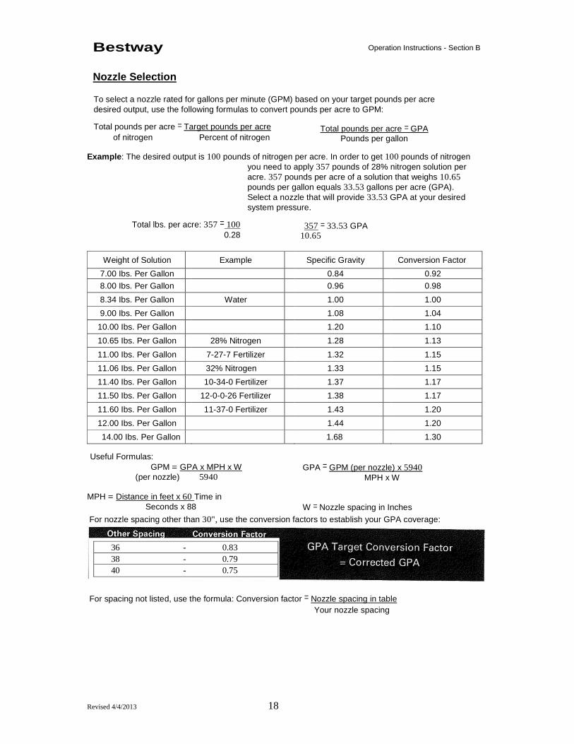
Bestway Nozzle Selection
Operation Instructions - Section B
To select a nozzle rated for gallons per minute (GPM) based on your target pounds per acre desired output, use the following formulas to convert pounds per acre to GPM: Total pounds per acre = Target pounds per acre
of nitrogen Percent of nitrogen
Total pounds per acre = GPA Pounds per gallon
Example : The desired output is 100 pounds of nitrogen per acre. In order to get 100 pounds of nitrogen
you need to apply 357 pounds of 28% nitrogen solution per acre. 357 pounds per acre of a solution that weighs 10.65 pounds per gallon equals 33.53 gallons per acre (GPA). Select a nozzle that will provide 33.53 GPA at your desired system pressure.
Total lbs. per acre: 357 = 100 0.28
357 = 33.53 GPA 10.65
Weight of Solution Example Specific Gravity Conversion Factor
7.00 Ibs. Per Gallon 0.84 0.92
8.00 Ibs. Per Gallon 0.96 0.98
8.34 Ibs. Per Gallon Water 1.00 1.00
9.00 Ibs. Per Gallon 1.08 1.04
10.00 Ibs. Per Gallon 1.20 1.10
10.65 Ibs. Per Gallon 28% Nitrogen 1.28 1.13
11.00 Ibs. Per Gallon 7-27-7 Fertilizer 1.32 1.15
11.06 Ibs. Per Gallon 32% Nitrogen 1.33 1.15
11.40 Ibs. Per Gallon 10-34-0 Fertilizer 1.37 1.17
11.50 Ibs. Per Gallon 12-0-0-26 Fertilizer 1.38 1.17
11.60 Ibs. Per Gallon 11-37-0 Fertilizer 1.43 1.20
12.00 Ibs. Per Gallon 1.44 1.20
14.00 Ibs. Per Gallon 1.68 1.30 Useful Formulas:
GPM = GPA x MPH x W (per nozzle) 5940
MPH = Distance in feet x 60 Time in Seconds x 88
GPA = GPM (per nozzle) x 5940 MPH x W
W = Nozzle spacing in Inches For nozzle spacing other than 30", use the conversion factors to establish your GPA coverage:
For spacing not listed, use the formula: Conversion factor = Nozzle spacing in table
Your nozzle spacing
36 - 0.83 38 - 0.79 40 - 0.75

Revised 4/4/2013 19
Bestway
Nozzle Specifications+
Operation Instructions - Section B
Nozzle* PSI GPM GPA at 30” Nozzle Spacing**
(per nozzle) 4 MPH 6 MPH 8 MPH 10 MPH
10 0.20 9.9 6.6 5.0 4.0 H1/4U- 20 0.28 13.9 9.2 6.9 5.5 SSOO04 30 0.35 17.3 11.6 8.7 6.9
40 0.40 19.8 13.2 9.9 7.9 10 0.30 14.9 9.9 7.4 5.9
H1/4U- 10 0.42 20.8 13.9 10.4 8.3 SSOO06 30 0.52 25.7 17.2 12.9 10.3
40 0.60 29.7 19.8 14.9 11.9 10 0.40 19.8 13.2 9.9 7.9
H1/4U- 20 0.57 28.2 18.8 14.1 11.3 SSOO08 30 0.69 34.2 22.8 17.1 13.7
40 0.80 39.6 26.4 19.8 15.8
10 0.50 24.8 16.5 12.4 9.9 H-1/4U- 20 0.71 35.1 23.4 17.6 14.1 SS0010 30 0.87 43.1 28.7 21.5 17.2
40 1.00 49.5 33.0 24.8 19.8 10 0.75 37.1 24.8 18.6 14.9
H1/4U- 20 1.06 52.5 35.0 26.2 21.0 SS0015 30 1.30 64.4 42.9 32.2 25.7
40 1.50 74.3 49.5 37.1 29.7 10 1.00 49.5 33.0 24.8 19.8
H1/4U- 20 1.41 69.8 46.5 34.9 27.9
SS0020 30 1.73 85.6 57.1 42.8 34.3
40 2.00 99.0 66.0 49.5 39.6 10 1.50 74.3 49.5 37.1 29.7
H1/4U- 20 2.12 104.9 70.0 52.5 42.0 SS0030 30 2.60 128.7 85.8 64.4 51.5
40 3.00 148.5 99.0 74.3 59.4
10 2.50 123.8 82.5 61.9 49.5
H1/4U- 20 3.54 175.2 116.8 87.6 70.1
SS0040 30 4.53 224.2 149.5 112.1 89.7
40 5.00 247.5 165.0 123.8 99.0
10 3.00 148.5 99.0 74.3 59.4 H1/4U- 20 4.24 209.9 139.9 104.9 84.0 SS0050 30 5.20 257.4 171.6 128.7 103.0
40 6.00 297.0 198.0 148.5 118.8
10 3.00 148.5 99.0 74.3 59.4 H1/4U- 20 4.24 209.9 139.9 104.9 84.0 550060 30 5.20 257.4 171.6 128.7 103.0
40 6.00 297.0 198.0 148.5 118.8
+ Nozzle specification on TeeJet® StreamJet® spray nozzles copied from TeeJet® catalog 50A, page 51. * Nozzle or tip (TP). Tip used with the standard TeeJet® cap. Nozzles are threaded with BSPT threads.
** Use the conversion factor for other nozzle spacings.
Revised 4/4/2013 20
Bestway
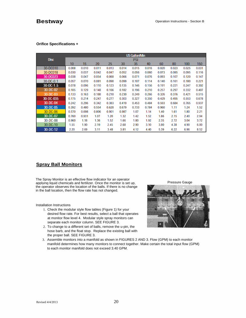
Orifice Specifications +
Operation Instructions - Section B
Spray Ball Monitors
The Spray Monitor is an effective flow indicator for an operator applying liquid chemicals and fertilizer. Once the monitor is set up, the operator observes the location of the balls. If there is no change in the ball location, then the flow rate has not changed.
Installation Instructions 1. Check the modular style flow tables (Figure 1) for your
desired flow rate. For best results, select a ball that operates at monitor flow level 4. Modular style spray monitors can separate each monitor column. SEE FIGURE 3.
2. To change to a different set of balls, remove the u-pin, the hose barb, and the float stop. Replace the existing ball with the proper ball. SEE FIGURE 3.
3. Assemble monitors into a manifold as shown in FIGURES 2 AND 3. Flow (GPM) to each monitor manifold determines how many monitors to connect together. Make certain the total input flow (GPM) to each monitor manifold does not exceed 3.40 GPM.
Pressure Gauge

Revised 4/4/2013 21
Bestway Operation Instructions - Section B
Figure 2
Figure 3
FIGURE 1

Revised 4/4/2013 22
Bestway
NOTES:
Safety Instructions - Section B
Revised 4/4/2013 23
Maintenance & Service Section C

Revised 4/4/2013 24
Bestway
IMPORTANT
Structure
Maintenance, Service and Troubleshooting - Section C
Proper maintenance of the Fertilizer Applicator and the tractor is critical for peak performance, reliability and accuracy of this system. The following is a guideline of the type of maintenance and servicing that should be performed on this unit. Your environment and uses may require additional maintenance and service beyond this list to assure a reliable and safe unit. The operator of this unit has ultimate responsibility to identify areas of concern and rectify them before they become a hazard or safety issue. There is no substitute for a trained, alert operator.
Inspect all welds and structural components for tears, bends, cracks, or other damage. This unit may operate in a corrosive environment. Make sure all corrosion is remove and repainted.
Hydraulics
1. Inspect cylinder shafts for corrosion or damage. Repair or replace shaft to avoid hydraulic leaks or cylinder failure.
2. Inspect hydraulic hoses. Replace any hose that shows signs of wear or damage.
Electrical and Lighting System
1. Inspect lights for any damage and operation. Replace any lights that are not in good condition.
2. Inspect wiring for chafing or damage. Repair or replace any wiring that is damaged. 3. Inspect safety decals. Replace any decals that are worn, faded, or damaged. Bestway, Inc.
for replacements.
DANGER
If any of the above inspections, or others identified, are discovered REPAIR IMMEDIATELY. Do not put this unit into operation with any questionably maintained parts. Poor performance or a hazard may occur.

Revised 4/4/2013 25
Bestway
Lubrication
Maintenance, Service and Troubleshooting - Section C
1. Always lubricate the 1000 Series Fertilizer
Applicator before bringing the machine to the field. Grease fittings are located on the hinges of folding tool bars.
2. Stop the tractor, set the parking brake and turn off the engine before performing maintenance or lubricating the machine.
3. Grease fittings at least daily. Grease coulters every 10 hours.
4. Clean grease fittings before lubricating. 5. If grease fittings are missing or damaged,
replace the fittings to ensure lubrication. 6. Use a high quality lubricating grease per the
intervals shown on the drawing. 7. Optional equipment may require additional greasing.
Refer to the instruction manuals for pump drives, pumps, coulters, etc. for specific maintenance instructions.
This applicator is designed to be lubricated daily in normal conditions, and more frequently under severe conditions.

Revised 4/4/2013 26
Bestway
Preventative Maintenance
Maintenance, Service and Troubleshooting - Section C
Wheel and Coulter Bearings Repack coulter and wheel bearings every 250 hours. 1. Remove hubs and bearings from machine. 2. Clean bearings and hubs of old grease. 3. Inspect hub, bearings, and seal for damage. 4. Replace if necessary. 5. Repack cones and fill hub cavities with a good
wheel bearing grease.
Coulter hubs a. Assemble and torque nut to 15 ft Ibs while rotating hub to seat hub and seal. b. Loosen nut one slot and check that hub rotates freely. Install Cotter pin. c. Fill cap with grease and replace cap.
Gauge wheel bearing hubs a. Assemble and torque nut to 75 ft-lbs while rotating hub to seat hub and seal. b. Loosen nut and re-torque to 45 ft-Ibs while rotating hub. c. Loosen nut one slot and check that hub rotates freely. Install cotter pin. Do not loosen nut
more than 30 degrees to install cotter pin. d. Fill cap with grease and replace cap.
DANGER
Block the machine securely before performing any maintenance on the machine. Do not let the machine fall.
Cylinder Rods Coat the exposed shaft with grease during machine storage to prevent rust.
Pre-Season Startup Check 5. Review this manual for proper operation of the machine. 6. Check that all bolts are tight. Re-tighten bolts to proper torque. 7. Inspect coulters, knives or injectors and replace components if they are worn. 8. Check tires for proper inflation. Inflate tires to manufacturer’s specifications. 9. Check wheel lug nuts. Re-tighten if necessary. 10. Inspect and repack or replace coulter and wheel bearings and seals. 11. Inspect hoses, monitors, and hydraulic hoses for fraying. DO NOT USE HANDS TO
CHECK FOR LEAKS ON HYDRAULIC HOSES. 12. Check all lights and visibility decals. Replace faded decals and burnt out bulbs.
Post-Season Storage 1. The liquid applied with the Bestway Applicator is very corrosive. Thoroughly clean the machine
before placing it in storage. Flush all liquid lines with RV antifreeze. 2. Inspect machine for worn parts. Note parts for replacement during the off-season. 3. Repaint all areas where paint has worn off. 4. Lubricate the machine. 5. Apply a thin layer of grease to all coulters and exposed cylinder shafts. 6. Store the machine inside to increase the life of plastic and rubber components. 7. Use cylinder lockups in storage to prevent the toolbar from settling. 8. Refer to the owners manuals for optional equipment such as the pump for specific care.
IMPORTANT
Failure to check and maintain the proper lug nut torque could result in elongation of rim and/or broken lug-bolts. We recommend checking lug nut torque periodically to insure proper wheel tightness on Bestway Fertilizer Applicator.

Revised 4/4/2013 27
Bestway
Bolt Torque Data
Maintenance, Service and Troubleshooting - Section C
The chart provided contains information concerning standard hardware used on this machine. It is recommended that all fasteners be tightened to the torque values specified. The grade of the bolt is identified by the markings on the head of the bolt.
General Bolt Torque Data in 1 Ft Lbs
BOLT SAE - GRADE 5 SAE - GRADE 8 SIZE DRY LUB DRY LUB
1/4-20 8 6 12 9
1/4-28 9 7 13 10
5/16-18 17 13 25 18
5/16-24 19 14 25 20
3/8-16 30 23 45 35
3/8-24 35 25 50 40
7/16-14 50 35 70 50
7/16-20 55 40 80 60
1/2-13 78 55 110 80
1/2-20 90 65 120 90
9/16-12 110 80 150 110
9/16-18 120 90 170 130
5/8-11 150 110 220 170
5/8-18 170 130 240 180
3/4-10 260 200 380 280
3/4-16 300 220 420 320
7/8-9 430 320 600 460
7/8-14 470 350 660 500
1-8 640 480 900 680
1-14 700 530 1000 740
WARNING
Do Not use values in place of those specified in other sections of this manual or contained in information published by the manufacturer of the components in question.

Revised 4/4/2013 28
Bestway
NOTES:
Safety Instructions - Section C

Revised 4/4/2013 29
Parts & Schematics Section D

Revised 4/4/2013 30
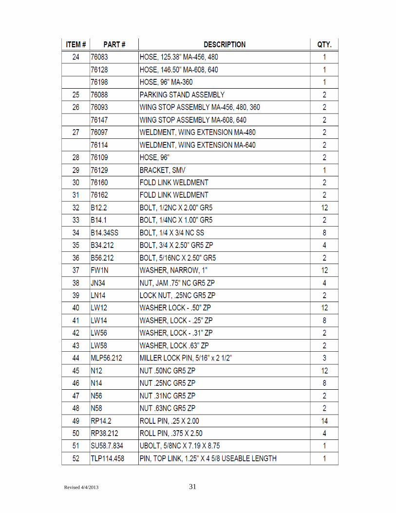
Revised 4/4/2013 31

Revised 4/4/2013 32

Revised 4/4/2013 33
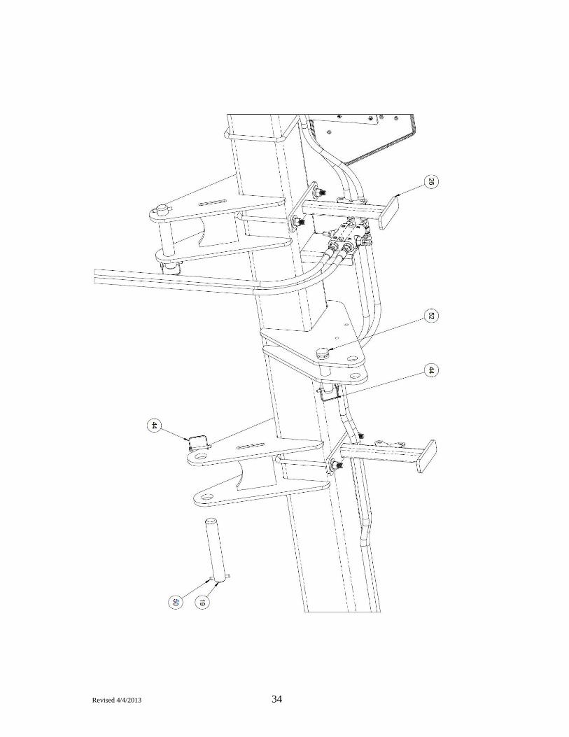
Revised 4/4/2013 34
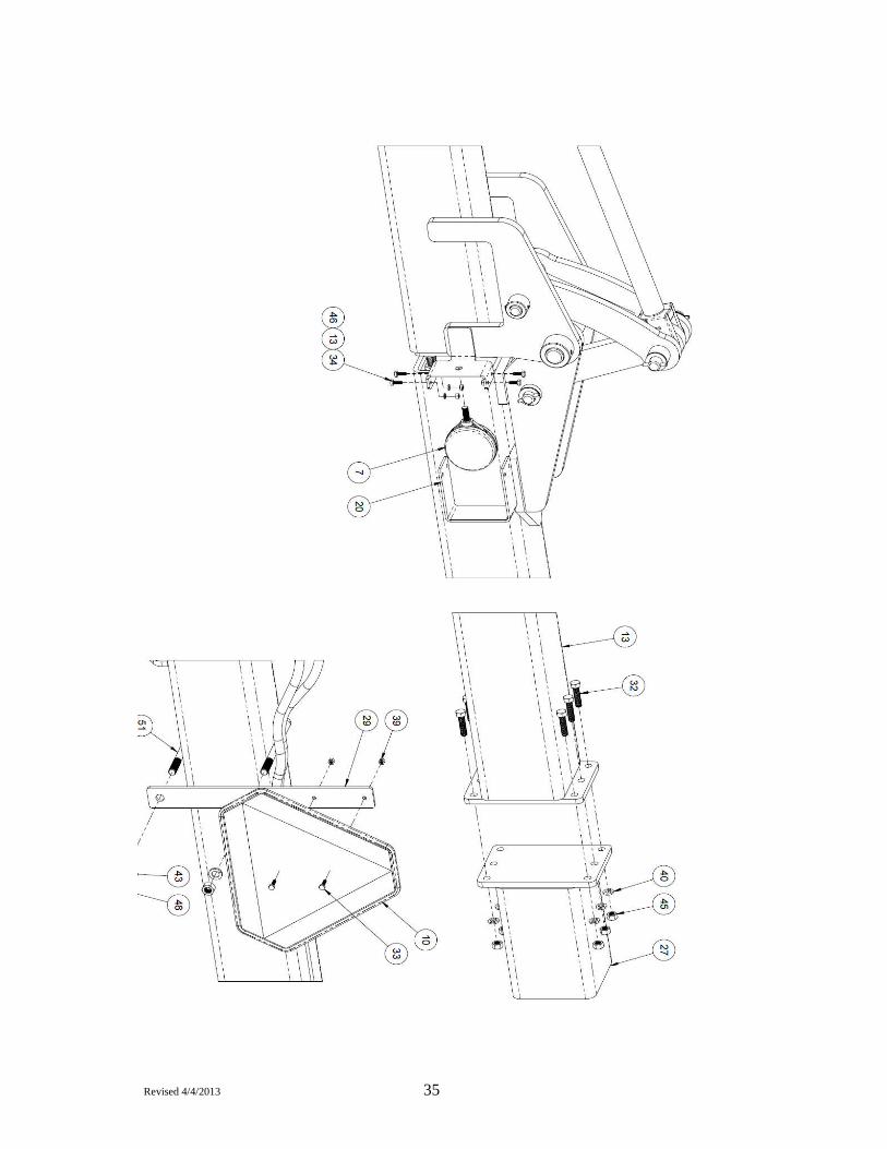
Revised 4/4/2013 35

Revised 4/4/2013 36

Revised 4/4/2013 37

Revised 4/4/2013 38

Revised 4/4/2013 39

Revised 4/4/2013 40

Revised 4/4/2013 41

Revised 4/4/2013 42

Revised 4/4/2013 43

Revised 4/4/2013 44

Revised 4/4/2013 45
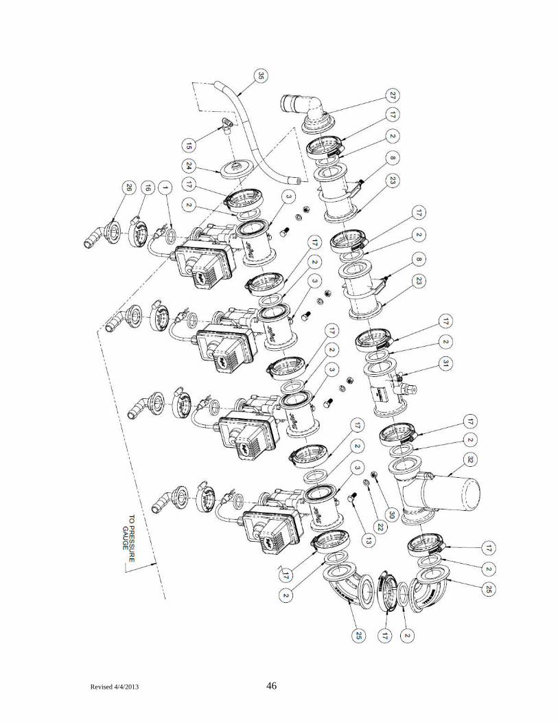
Revised 4/4/2013 46

Revised 4/4/2013 47
Revised 4/4/2013 48

Revised 4/4/2013 49

Revised 4/4/2013 50
Warranty & Serial Information Section E

Revised 4/4/2013 51
Bestway
Serial and Model Number Location
Left hand side of the upper 3pt link. (as seen in photo)
Warranty - Section E
The following page contains a space for you to record the information about your Fertilizer Applicator found on this plate. Please record this information here for future reference.
SERIAL NUMBER INFORMATION
Bestway Model Number: _____________________________________________________
Bestway Serial Number: ____________________________________________________ Component Serial Numbers:
Manufacturer Part Number
Serial No.
Notes:
IMPORTANT
This manual and the manuals for optional equipment included with it are a sub-component of this applicator unit and should go with the unit in the event of a future sale. This information contained within this binder is specific to this applicator unit and cannot easily be replaced,

Revised 4/4/2013 52
Bestway
Warranty - Section E

Revised 4/4/2013 53
This page intentionally left blank.


