ORBITER FLIGHT DECK REDESIGN (A PHYSICAL LAYOUT FOR A FUTURISTIC FLIGHT DECK) Final Report NASNASEE Summer Faculty Fellowship Program--1995 Johnson Space Center Prepared By: Academic Rank: University & Department: NASNJSC Directorate: Division: Branch: JSC Colleague: Date Submitted: Contract Number: Mehrzad Khorsandi Assistant Lecturer Texas A&M University Civil Engineering Dept. Engineering Design Graphics College Station, TX. 77843 Space and Life Sciences Flight Crew Support Graphic Research and Analysis Facility (GRAF) James Maida October 30,1995 NGT-44-00 1-800 12-1 https://ntrs.nasa.gov/search.jsp?R=19960050290 2018-05-28T15:43:34+00:00Z
Transcript
ORBITER FLIGHT DECK REDESIGN (A PHYSICAL LAYOUT FOR A FUTURISTIC FLIGHT DECK)
Final Report NASNASEE Summer Faculty Fellowship Program--1995
The purpose of this summer project was to develop a set of schematic drawings for resdesign of the Space Shuttle flight deck from which a three dimensional computer drawings can be built and viewed in a virtual environment. In order to achieve this goal, first recommendations for overall redesign of Space Shuttle previously made by experts in the field were reviewed and relevant information were extracted and delineated. Original drawings of the Space Shuttle made by Rockwell were obtained and carellly examined. In order to implement and assess any modifications in terms of space saving parameters, it was determined that the drawings alone could not achieve this objective. As a complement, physical measurements of the mockup of Space Shuttle flight deck were made and the information was categorized and properly labeled on the original drawings. Then, space- saving redesign ideas, as motivated by expert recommendations on such things as information display panel upgrade by technologically advanced flat display units, were implemented. Next, the redesign ideas were executed on the Forward flight deck, Overhead Console, Right and Left Console, and Center Console. A new 3-D computer drawing of this was developed by modifying the existing drawing on the in-house developed software (PLAID). Finally, the drawing was transported to a Virtual Environment and observed.
12-2
INTRODUCTION
Background:
In order to keep Space Shuttle operating smoothly in the hture, the current cabin, its equipments, and its operation should be redesigned. The new futuristic cabin which includes the latest and the most advanced technological equipments should help operate the Space Shuttle in a more suitable, reliable, economical, and safe manner. The Orbiter Advanced Cabin Design has been under consideration for many years and many studies have been done to satis@ this need. Some of the major issues in this relation are: 1) The cabin equipments and flight crew's use of them are archaic; 2) The cost of operation and maintenance through the use of the current obsolete
3) Use of new, more advanced, and lighter weight equipment could help achieve cabin
4) Use of more advanced information systems could result in crew size reduction; and 5 ) The expected one billion dollar budget cut in the Space Shuttle program for 1996
equipment are considerably high;
weight reduction allowing for higher payload to be hauled to the orbit;
fiscal year makes cost cutting measures more imperative.
The archaic equipment currently used in the Space Shuttle are heavy and occupied large volume as compared to the most advanced technological equipments. For example, the bulky Cathode Ray Tubes (CRT) used as display in the Forward flight deck can be replaced with modem light weight and flat display units. The focus of this Summer project was to redesign the interior of the flight deck to increase space and decrease weight, taking advantage of these technological advancements.
Objectives:
The first objective of this project was the preliminary design of the flight deck based on the recommendations previously made by the experts in the aeronautic and avionic field. The second objective was to prepare a computer model of the proposed changes to the flight deck which could be viewed in virtual environment for review and possible modifications.
EXPERTS RECOMMENDATIONS
To become familiar with the background of the flight deck redesign and arrive at the objectives of this project many NASA memos were provided which were mostly cost saving recommendations of the experts of the field for the space shuttle. Also many more articles and books were recommended as references. Even though some of them were very hard to find in short period of time but they were all very useful to the design process.
12-3
There were two types of expert recommendations provided along with the project description, to reduce the operating and maintenance cost of the Space Shuttle. The first type were general recommendations for a futuristic Space Shuttle as a whole. The second type were specific recommendations for a futuristic flight deck. A summary of these follows.
General Recommendations
These recommendations were made based on the goal of 50% reduction in the Space Shuttle maintenance and operating cost. 1) Use of integrated navigation system 2) Use of electronic integrated orbiter. 3) Use of Multifunction Electronics Display Subsystem. 4) Use of Fiber-Optics. 5 ) Use of Star Tracker Cameras 6) Use of Solid State Data Recorders. 7) Use of &-Board Automation. 8) Use of Electronic Voice Communication. 9) Crew size reduction.
Expert Recommendations Specifically for Flight Deck
1) Removal of the Center Console. 2) Removal of the two Side Consoles. 3) Removal of the Over Head Console. 4) Reduction of window acreage. 5 ) Flattening of the Forward Station (based on the use of the most advanced and less
space taking equipment). 6) Flattening the AFT Station. 7) Cockpit Redesign / Flightcrew Escape.
THE DESIGN PROCESS
The design process consisted of two phases. The first phase was to incorporate the expert recommendations for the redesign of the flight deck and present them in the form of sketch. This phase took the major part of the summer work. The second phase consisted of taking only the space saving ideas for the Forward flight deck from the first phase and implementing and incorporating them in an existing 3D drawing of flight deck.
12-4
First Phase of Design
The first phase needed much of the data gathering and data organization, physical measurement of the mockup, and study of the original drawings of the flight deck to clearly understand the space we were to work with and design. These drawings were prepared nearly thirty years ago by Rockwell and they are currently used on an every day basis for any alteration or maintenance to the Space Shuttle. The last part of this phase included sketching of the redesign ideas.
Data Gathering- Several references in form of NASA memos were provided, along with the problem statement. These were studied along with other relevant books, articles, and memos. Although the acquisition of data and documents was sometimes difficult and time consuming, partly due to sensitive nature of some of them, the overall process was a beneficial learning experience. This was an essential stage in the design process for becoming familiar with the space and area one has to work with. It also helped to set the stage for the next step of design which was the actual mockup measurement.
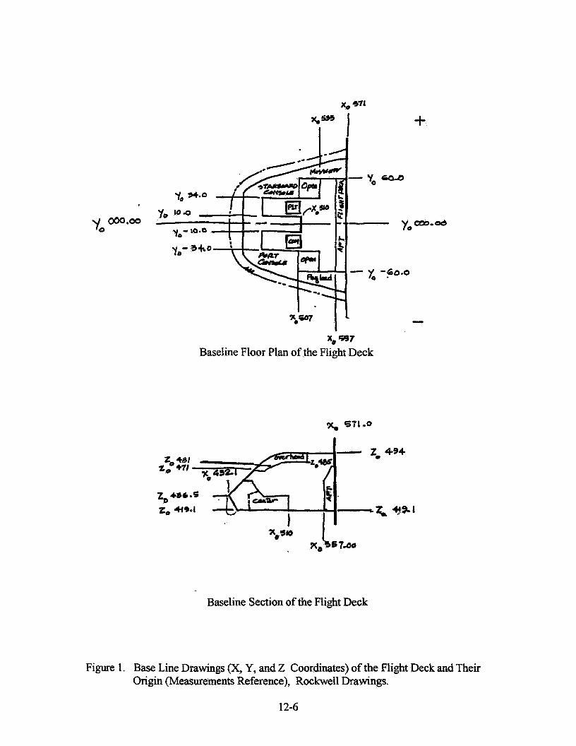
Studv of the Original Drawings of the Flight Deck- In order to understand the working space (space to be redesigned) within the flight deck the original drawings of the flight deck by Rockwell were obtained. These drawing were specially useful in providing information about the hidden spaces, which are commonly located under the panels that are to be replaced with more advanced equipment. However, the fact that some of the drawing are very hard to locate, their sizes are not practical for this kind of overall redesign. In order to read original flight deck's drawing one must become familiar with zero base origin for X, Y, and Z coordinates used throughout the Rockwell drawings for flight deck, and at all time take those into account (See Figure 1). Still the exact or even the approximate sizes of the working space (space to redesign) within flight deck could not be easily obtained from the origural drawings. While dimensions for some of the individual pieces were given on separate drawings but the overall drawings (Isometrics, sections, and complete views of flight deck such as Forward and Aft) lacked dimensions and specifications. Therefore, after the study of these drawings it was concluded that it would be more efficient to do an actual measurement of the mockup as describe below.
Phvsical Measurement of the Mockup. The physical measurement of the mockup and identification of its panels started by visiting the building (building 9B) where most mockups are located and video taping the flight deck, mid deck and other relevant areas. The video tape was viewed in order to determine the significant areas to be measured. The actual measurements and part identification of the flight deck took place for a few days on regular basis with the help of some of the engineers on sight. In addition to resolving some of the obscure points in the original drawings, physical measurement of the mockup was very useful in gaining better understanding and becoming more familiar with the redesign of the spaces under study.
12-5
m.00
x, 374
xo -7 Baseline Floor Plan of the Flight Deck
Baseline Section of the Flight Deck
Figure I. Base Line Drawings (X, Y, and 2 Coordinates) of the Flight Deck and Their origin (Measurements Reference), Rockwell Drawings.
12-6
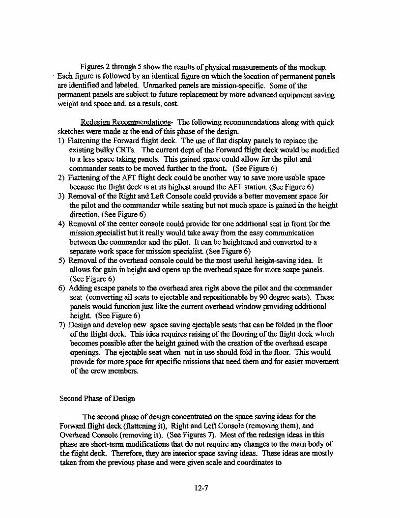
Figures 2 through 5 show the results of physical measurements of the mockup. . Each figure is followed by an identical figure on which the location of permanent panels
are identified and labeled. Unmarked panels are mission-specific. Some of the permanent panels are subject to future replacement by more advanced equipment saving weight and space and., as a result, cost.
Redesign Recommendations- The following recommendations along with quick sketches were made at the end of this phase of the design. 1) Flattening the Forward flight deck. The use of flat display panels to replace the
existing bulky CRTs. The current dept of the Forward flight deck would be modified to a less space taking panels. This gained space could allow for the pilot and commander seats to be moved further to the front. (See Figure 6)
2) Flattening of the AFT flight deck could be another way to save more usable space because the flight deck is at its highest around the AFT station. (See Figure 6)
3) Removal of the Right and Lefi Console could provide a better movement space for the pilot and the commander while seating but not much space is gained in the height direction. (See Figure 6)
4) Removal of the center console could provide for one additional seat in front for the mission specialist but it really would take away from the easy communication between the commander and the pilot. It can be heightened and converted to a separate work space for mission specialist. (See Figure 6)
5) Removal of the overhead console could be the most usefid height-saving idea. It allows for gain in height and opens up the overhead space for more scape panels. (See Figure 6)
6) Adding escape panels to the overhead area right above the pilot and the commander seat (converting all seats to ejectable and repositionable by 90 degree seats). These panels would function just like the current overhead window providing additional height. (See Figure 6)
7) Design and develop new space saving ejectable seats that can be folded in the floor of the flight deck. This idea requires raising of the flooring of the flight deck which becomes possible after the height gained with the creation of the overhead escape openings. The ejectable seat when not in use should fold in the floor. This would provide for more space for specific missions that need them and for easier movement of the crew members.
Second Phase of Design
The second phase of design concentrated on the space saving ideas for the Forward flight deck (flattening it), Right and Left Console (removing them), and Overhead Console (removing it). (See Figures 7). Most of the redesign ideas in this phase are short-term modifications that do not require any changes to the main body of the flight deck. Therefore, they are interior space saving ideas. These ideas are mostly taken fiom the previous phase and were given scale and coordinates to
12-7
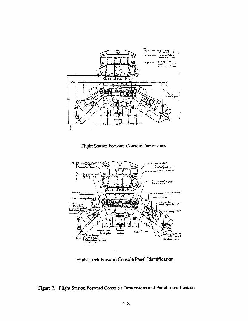
Flight Station Forward Console Dimensions
Flight Deck Forward Console Panel Identification
Fimwe 2. Flight Station Forward Console's Dimensions and Panel Identification.
12-8
Flight Deck Center Console Panel Identification
Fiewe 3. Flight Station Center Console's Dimensions and Panel Identification.
12-9
-1
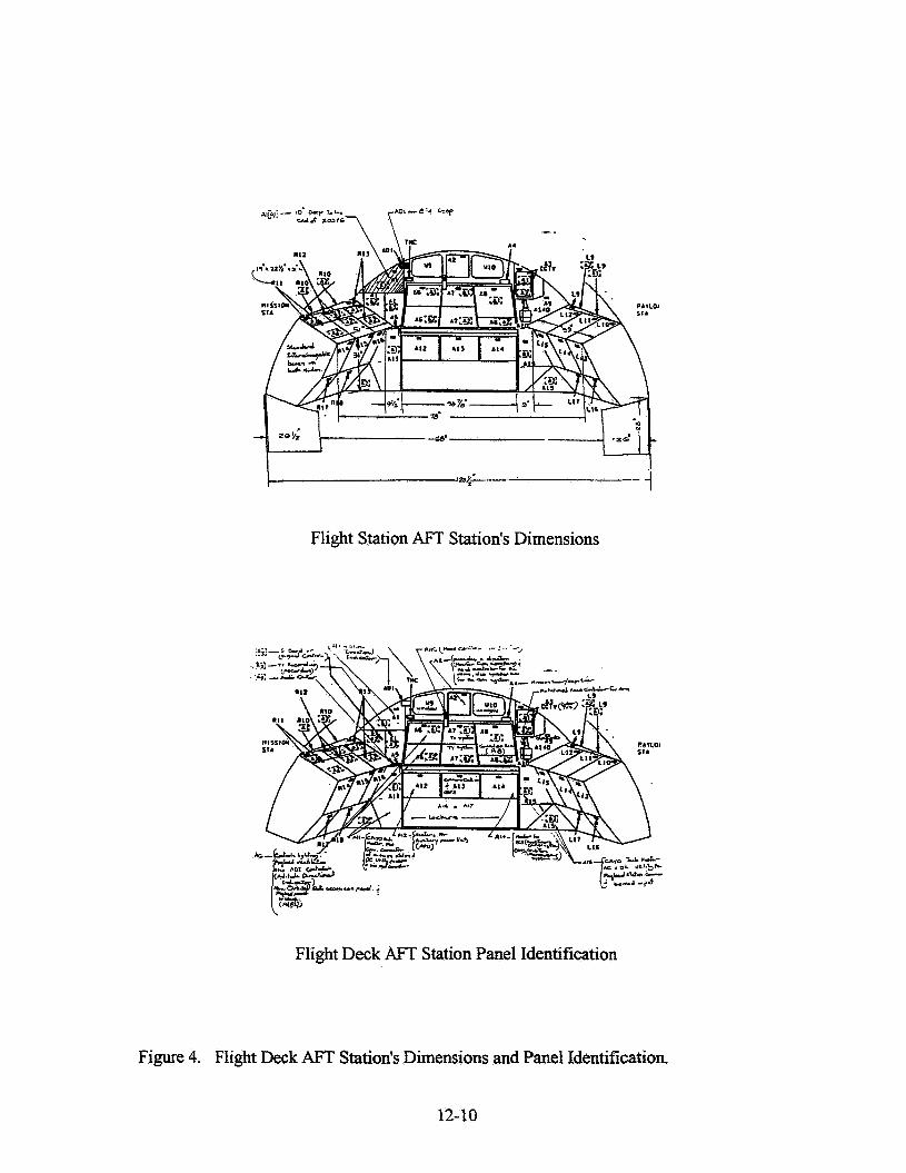
Flight Station AFT Station's Dimensions
Flight Deck AFT Station Panel Identification
Figure 4. Flight Deck AFT Station's Dimensions and Panel Identification.
12-10
Flight Deck Floor Plan (Existing Arrangement)
Flight Deck in Section (Dimensions)
Figure 5. Flight Deck Existing Floor Arrangements and Dimensions.
12-1 1
Flight Deck in Section (Redesigned Arrangement)
Figure 6. Flight Deck's Proposed Space Saving Floor Pian Arrangement.
12-12
Flight Deck Existing Arrangement
Flight Deck Proposed New Arrangement
Figure 7. Flight Deck Forward, Side Consoles, Overhead, and Center Console Arrangements.
12-13
be incorporated on a 3D existing computer drawing of the flight deck. The existing 3D computer drawing were originally created through the use of an in-house developed software called PLAID. This of the GRAPH Lab staff. After modification of e m redesign ideas, the revised 3D drawing was viewe helpful tool in getting the feel of the newly created space without having to build a physical model. It can also be used for future modification by a virtual experience of the actual spaces. The 111 potential of this tool is yet to be realized.
CONCLUSIONS AND FUTURE RECOMMENDATIONS
Redesign of the Space Shuttle flight deck is a process that requires coming together of many different components. In this project we focused on defining and testing some steps for implementation of this task with particular attention to space- saving concepts . Expert recommendation for overall redesign of Space Shuttle were reviewed and relevant information were extracted and delineated. Original drawings of the Space Shuttle made by Rockwell were obtained and careklly examined. In order to implement and assess any modifications in terms of space saving parameters, it was determined that the drawings alone could not achieve this objective. As a complement, physical measurements of the mockxp of Space Shuttle flight deck were made and the information was categorized and properly labeled on the original drawings. Then, space- saving redesign ideas, as motivated by expert recommendations on such things as information display panel upgrade by technologically advanced flat display units, were implemented. Next, the redesign ideas were executed on the forward flight deck, overhead console, right and left console, and center console. A new 3-D computer drawing of this was developed by modifying the existing drawing on the in-house developed software (PLAID). Finally, the drawing was transported to a Virtual Environment and observed
In order to perform the complete process of redesigning the flight deck exactly, a complete detailed electronic 3-D computer model of the entire current base-line Shuttle flight deck (FWD and AFT) is needed. Such a model could be used for the redesign and m e r analysis of the Space Shuttle Flight Deck. It should have a data base that would allow the user to be able or remove or attach any part(s) within the 3-D model and accurately asses the amount of space (e.g., in cubic feet) and weight (e.g., in pounds) gained or lost. Then redesign idea could be applied much more easily and the changes would be estimated more precisely.
12-14
REFERENCES
(1) "Advanced Trends in Avionics," Jim Curran, Iowa State University Press, 1992.
(2) Shuttle Avionics Upgrade Investigations, date 7/26/93, Naval Air Warfare Center, Aircraft Division, Indianapolis, IN.
(3) Clementine: "An Experiment to Flgith Quality Lightweight Space Technologies," Pedro L. Rustan.
(4) JSC memo ACS-90-49, date 1 1/28/90, "Orbiter Advance Displays".
( 5 ) JSC memo ACS-94-02, dated 1/10/94, "What Is Obsolete Around Here?"