Page 1
i
PRELIMINARY DESIGN OF PARAXYLENE PLANT
USING SELECTIVE TOLUENE DISPROPORTIONATION PROCESS
CAPACITY OF 400,000 TON/ YEAR
by:
Delta Mutiara
D500122006
Supervisor:
1. Dr. Ir. Ahmad M Fuad, M.T.
2. Ir. Herry Purnama, M.T., Ph.D.
CHEMICAL ENGINEERING DEPARTMENT
FACULTY OF ENGINEERING
UNIVERSITAS MUHAMMADIYAH SURAKARTA
2017
Page 2
268'>IIN
lueuluedeclJo pEoH
LIAZ Arenrqec g '€uel€rns
',(q pe,tordd€ ueeq seH
t99')IN
@
rffi I11 rost,r.redng
'C'rld "I'hl'eureu;n6,{;.lag ..11 .7
'J'hl'lpenc'l peLuqv.rl.rcl'l
reeA/suoJ 000,00t,fircudu3
ssecoJd uorluuoryodo;dsrq euenloJ oArlcoles
Sursn 1uu14 aue1,(xere43:o uBrseq,(leurur1a;4
900 Tzt 00s cr
tIt\}nJN eleo
;osruedng
lcelor4luurCJo ollrJ
I^IIN
."-..B.l^ \
#9
,.\"-,'''i,:
8I9')IN
YIU\ilXYUNS IIVAI(IVNMIYHOIAI SVIISUf,AINN
DNIUf,f,NIONtr [O ATTNf,Y.{
CNIUtrflNICNfl 'IYJII ISHf, f O INgWIUVdf,(
TYAOUddY
'q'q4"cg'ryffi./
f..F
Page 3
iii
MOTTO
Forgive , Forget , keep learning and continuing growth
The best person is who the most benefits for others
Page 4
iv
DEDICATION
bismillahirahmanirrahim
I dedicate this work to:
My Heroes, Endang Wulan Sari and Suyono . Thank you for your endless love.
Many thanks for :
My brother n sister “ fantastic Five”Alva Dian Santri, Beta Muhammad Gilang
Septian , Gamma Rahma Pratiwi, Meggy Zulkarnaen Muhammad.Thank you for
support anything. You aresecond parent for me.
My cute classmate Aisyah Itsnaini solicheh, Anggie F Asokawati, Aisyah Hanifah,
Diah Ayu Anggraeni ,Imala Septi Cahyani , Salam nurdin Aridin, Yulira Kus
Rendra. We through all things together for 4 years more .You all are best gift in
my collge life
My patner TPP Listiani thank you for your cooperation ,patience and
accomodation :D :D “ finally we made our degree together” :D D
Lecturers and staffs in department chemical Engneering UMS 2012. Thank you so
much for support, guidance and encouragment
.Friends in chemical engineering UMS 2012, senior and junior . Thank for
sharing experiences and help me so much.
And for everyone who have helped me to finish this final project, i can not
mention one by one.
May Allah S.W.T bless us all
Page 5
v
PREFACE
Alhamdulillahirobbil ‘alamin, praise is merely to Almighty Allah SWT for
gracious mercy and blessing, so this final project has been completed.
This report is one of compulsory subjects to pass bachelor degree in
Department of Chemical Engineering, Faculty of Engineering, Universitas
Muhammadiyah Surakarta. In this opportunity author grateful to all those who
helped in completing Final Project Report in particular to:
1. Rois Fatoni, S.T., M.Sc., Ph.D as Chairman of Department Chemical
Engineering, Faculty of Engineering, Universitas Muhammadiyah
Surakarta
2. Dr.Ir. Ahmad M Fuadi, M.T as Supervisor I
3. Ir. Herry Purnama M.T., Ph.D as Supervisor II
4. Lecturers in Chemical Engineering Department, Universitas
Muhammadiyah Surakarta
5. Listiani as my partner in final project
6. Family and friends who have given endorsement and prayer
7. Everyone who has supported
Due to limitations in preparation of this report, author aware that this
report might have some shortcomings. Therefore suggestion and constructive
criticism to improve this report are welcome. Author wish this report will be
useful for all those who concern.
Surakarta, January 2017
Delta Mutiara
Page 6
vi
TABLE OF CONTENTS
COVER ................................................................................................................ i
VALIDATION ..................................................................................................... ii
MOTTO .............................................................................................................. iii
DEDICATION .................................................................................................... iv
PREFACE ............................................................................................................ v
TABLE OF CONTENTS .................................................................................... vi
LIST OF TABLES ............................................................................................... x
LIST OF FIGURES ............................................................................................ xii
ABSTRACT ....................................................................................................... xiii
CHAPTER I INTRODUCTION .......................................................................... 1
1.1. Background ................................................................................................... 1
1.2.Design capacity .............................................................................................. 2
1.3. Site selection ................................................................................................ 2
1.4.Literature Reviews ......................................................................................... 4
1.4.1. Kinds of process ................................................................................ 5
1.4.2. use of product ................................................................................... 7
1.4.3. Physical and chemical properties of raw materials and products ..... 8
CHAPTER II PROCESS DESCRIPTION ......................................................... 15
2.1. Specification of raw materials and products specification .......................... 15
2.2. Concept of process ....................................................................................... 16
2.2.1. Background process ......................................................................... 16
2.2.2. Reaction mechanism ........................................................................ 17
2.2.3. Kinetics overview ............................................................................ 19
2.2.4. Thermodynamics review .................................................................. 20
2.2.5. Operating condition .......................................................................... 22
2.3. Process step ................................................................................................. 23
2.3.1. Raw material storage stage............................................................... 23
2.3.2. Preparation of raw material stage ..................................................... 23
2.3.3. Reaction stage .................................................................................. 24
Page 7
vii
2.3.4. Separation and purification product stage ........................................ 24
2.3.5. Products storage stage ...................................................................... 25
2.3.6. Flow chart of process ....................................................................... 26
2.4. Mass and heat balance ................................................................................ 28
2.4.1. Mass balance .................................................................................... 28
2.4.2. Heat balance ..................................................................................... 32
2.5. Plant and process equipment layout ............................................................. 35
2.5.1. Plant layout ...................................................................................... 35
2.5.2. Process equipment layout ................................................................. 39
CHAPTER III SPECIFICATION OF EQUIPMENTS ...................................... 41
3.1. Main equipment ........................................................................................... 41
3.1.1. Specification of reactor (R-120) ........................................................ 41
3.1.2. Specification of distillation tower1 (D-140) ...................................... 42
3.1.3. Specification of distillation tower2 (D-160) ...................................... 42
3.1.4. Specification of crystalizer (E-170) ................................................... 43
3.2. Supporting equipment .................................................................................. 44
3.2.1. Specification of toluene tank ( F-110) ............................................... 44
3.2.2. Specification of benzene tank (F-150) ............................................... 45
3.2.3. Specification of paraxylene tank (F-190) .......................................... 45
3.2.4. Specification of compressor 1 (G-113) .............................................. 46
3.2.5. Specification of compressor 2 (G-132) .............................................. 47
3.2.6. Specification of compressor 3 (G-114) .............................................. 47
3.2.7. Specification of compressor 4 (G-115) ............................................. 47
3.2.8. Specification of vaporizer (V-121) .................................................... 48
3.2.9. Specification of furnace (Q-116) ....................................................... 49
3.2.10. Specification of separator (H-130) .................................................. 49
3.2.11. Specification of condenser 1 (E-143) .............................................. 50
3.2.12. Specification of condenser 2 (E-165) .............................................. 51
3.2.13. Specification of reboiler 1 (E-141) .................................................. 52
3.2.14. Specification of reboiler 2 (E-161) .................................................. 52
3.2.15. Specification of accumulator 1 (F-144) ........................................... 53
Page 8
viii
3.2.16. Specification of accumulator 2 (F-166) ........................................... 54
3.2.17. Specification of cooler 1 (E-146) ..................................................... 54
3.2.18. Specification of WHB (V-121) ........................................................ 55
3.2.19. Specification of expander 1 (G-122)................................................ 56
3.2.20. Specification of condensor 3 (E-123) .............................................. 56
3.2.21. Specification of heat exchanger 1 (E-163)....................................... 57
3.2.22. Specification of heat exchanger 2 (E-164)....................................... 57
3.2.23. Specification of heat centrifuge (H-172) ......................................... 58
3.2.24. Specification of screw conveyor 1 (J-171) ...................................... 59
3.2.25. Specification of screw conveyor 2 (J-173) ...................................... 59
3.2.26. Specification of melter (M-180) ...................................................... 60
3.2.27. Specification of pump 1 (L-111) ..................................................... 60
3.2.28. Specification of pump 2 (L-131) ..................................................... 61
3.2.29. Specification of pump 3 (L-145) ..................................................... 61
3.2.30. Specification of pump 4 (L-142) ..................................................... 62
3.2.31. Specification of pump 5 (L-167) ..................................................... 63
3.2.32. Specification of pump 6 (L-162) ..................................................... 63
3.2.33. Specification of pump 7 (L-174) ..................................................... 64
3.2.34. Specification of pump 8 (L-181) ..................................................... 64
CHAPTER IV UTILITIES AND LABORATORIES ........................................ 66
4.1. Process supporting unit ................................................................................ 66
4.2. Laboratory .................................................................................................... 78
4.3. Health and safety work ................................................................................ 80
CHAPTER V MANAGEMENT ......................................................................... 92
5.1.Form of company ......................................................................................... 92
5.2.Organizational structure ............................................................................... 94
5.3.Duties and authorities .................................................................................. 95
5.4.Research and development .......................................................................... 97
5.5.Working hours alocation .............................................................................. 98
5.6.Status of employees and wage system ........................................................ 100
5.7.Classification of position ............................................................................ 100
Page 9
ix
5.8.Employee’s socialwelfare ........................................................................... 102
5.9.Production management ............................................................................. 103
CHAPTER VI ECONOMIC ANALYSIS ......................................................... 106
6.1 Equipments’ price approximation ................................................................ 110
6.2 Result Calculation ........................................................................................ 112
6.3 Feasibility analysis ...................................................................................... 115
CHAPTER VII CONCLUSION ........................................................................ 143
BIBLIOGRAPHY
ATTACHMENT
Page 10
x
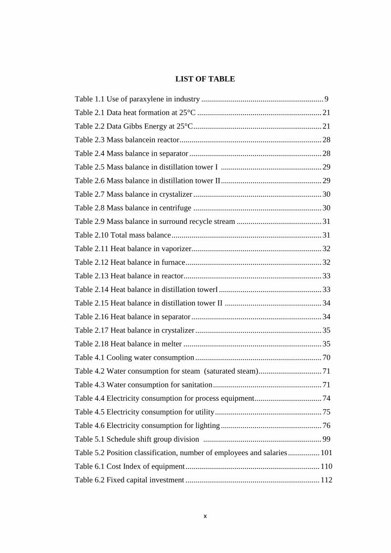
LIST OF TABLE
Table 1.1 Use of paraxylene in industry .............................................................. 9
Table 2.1 Data heat formation at 25°C ............................................................... 21
Table 2.2 Data Gibbs Energy at 25°C ................................................................. 21
Table 2.3 Mass balancein reactor ........................................................................ 28
Table 2.4 Mass balance in separator ................................................................... 28
Table 2.5 Mass balance in distillation tower I ................................................... 29
Table 2.6 Mass balance in distillation tower II ................................................... 29
Table 2.7 Mass balance in crystalizer ................................................................. 30
Table 2.8 Mass balance in centrifuge ................................................................. 30
Table 2.9 Mass balance in surround recycle stream ........................................... 31
Table 2.10 Total mass balance ............................................................................ 31
Table 2.11 Heat balance in vaporizer.................................................................. 32
Table 2.12 Heat balance in furnace ..................................................................... 32
Table 2.13 Heat balance in reactor...................................................................... 33
Table 2.14 Heat balance in distillation towerI .................................................... 33
Table 2.15 Heat balance in distillation tower II ................................................. 34
Table 2.16 Heat balance in separator .................................................................. 34
Table 2.17 Heat balance in crystalizer ................................................................ 35
Table 2.18 Heat balance in melter ...................................................................... 35
Table 4.1 Cooling water consumption ................................................................ 70
Table 4.2 Water consumption for steam (saturated steam) ................................ 71
Table 4.3 Water consumption for sanitation ....................................................... 71
Table 4.4 Electricity consumption for process equipment .................................. 74
Table 4.5 Electricity consumption for utility ...................................................... 75
Table 4.6 Electricity consumption for lighting ................................................... 76
Table 5.1 Schedule shift group division ............................................................ 99
Table 5.2 Position classification, number of employees and salaries ................ 101
Table 6.1 Cost Index of equipment .................................................................... 110
Table 6.2 Fixed capital investment .................................................................... 112
Page 11
xi
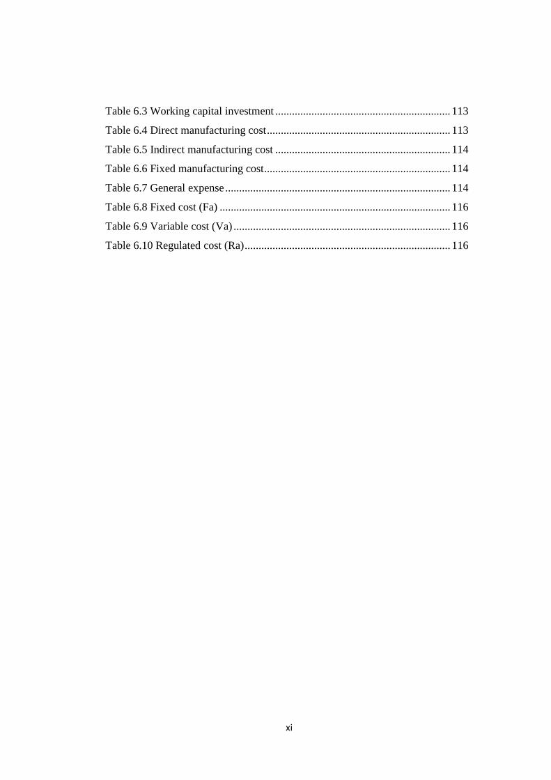
Table 6.3 Working capital investment ............................................................... 113
Table 6.4 Direct manufacturing cost .................................................................. 113
Table 6.5 Indirect manufacturing cost ............................................................... 114
Table 6.6 Fixed manufacturing cost ................................................................... 114
Table 6.7 General expense ................................................................................. 114
Table 6.8 Fixed cost (Fa) ................................................................................... 116
Table 6.9 Variable cost (Va) .............................................................................. 116
Table 6.10 Regulated cost (Ra) .......................................................................... 116
Page 12
xii
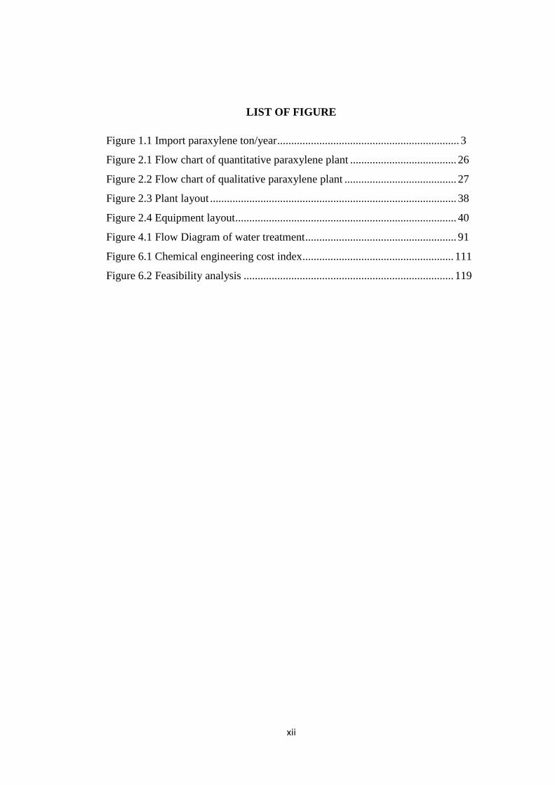
LIST OF FIGURE
Figure 1.1 Import paraxylene ton/year ................................................................. 3
Figure 2.1 Flow chart of quantitative paraxylene plant ...................................... 26
Figure 2.2 Flow chart of qualitative paraxylene plant ........................................ 27
Figure 2.3 Plant layout ........................................................................................ 38
Figure 2.4 Equipment layout ............................................................................... 40
Figure 4.1 Flow Diagram of water treatment ...................................................... 91
Figure 6.1 Chemical engineering cost index ...................................................... 111
Figure 6.2 Feasibility analysis ........................................................................... 119
Page 13
xiii
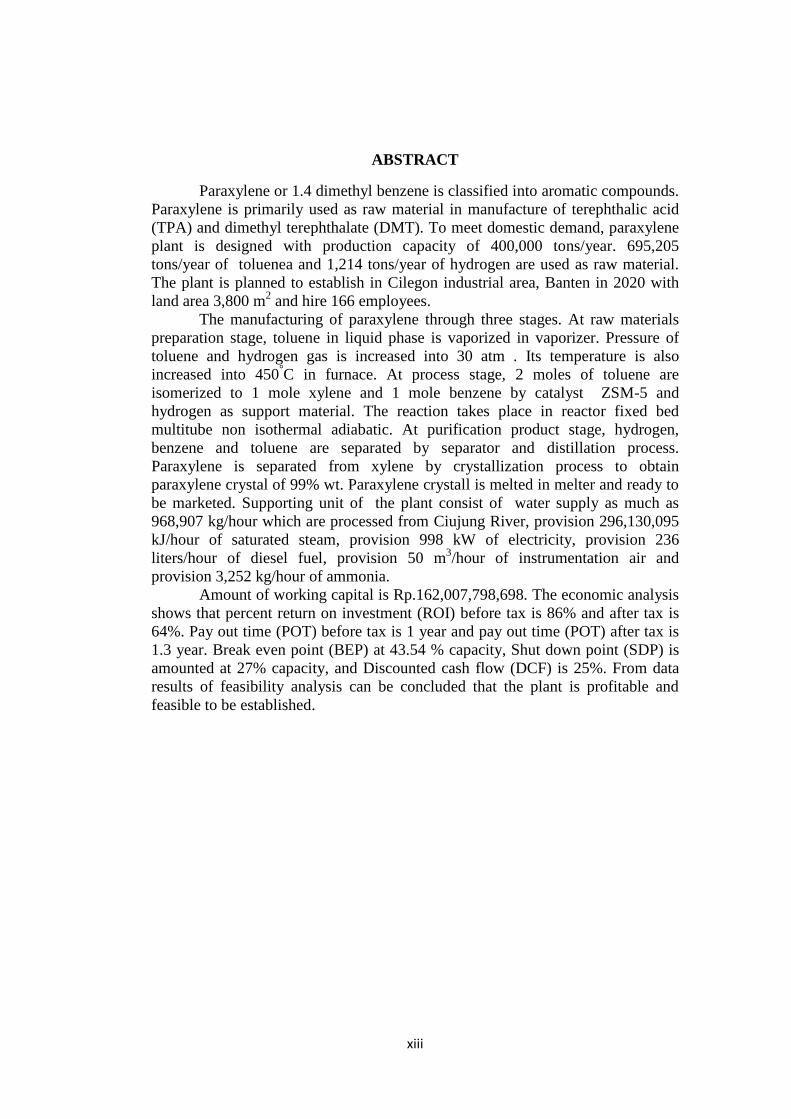
ABSTRACT
Paraxylene or 1.4 dimethyl benzene is classified into aromatic compounds.
Paraxylene is primarily used as raw material in manufacture of terephthalic acid
(TPA) and dimethyl terephthalate (DMT). To meet domestic demand, paraxylene
plant is designed with production capacity of 400,000 tons/year. 695,205
tons/year of toluenea and 1,214 tons/year of hydrogen are used as raw material.
The plant is planned to establish in Cilegon industrial area, Banten in 2020 with
land area 3,800 m2 and hire 166 employees.
The manufacturing of paraxylene through three stages. At raw materials
preparation stage, toluene in liquid phase is vaporized in vaporizer. Pressure of
toluene and hydrogen gas is increased into 30 atm . Its temperature is also
increased into 450°C in furnace. At process stage, 2 moles of toluene are
isomerized to 1 mole xylene and 1 mole benzene by catalyst ZSM-5 and
hydrogen as support material. The reaction takes place in reactor fixed bed
multitube non isothermal adiabatic. At purification product stage, hydrogen,
benzene and toluene are separated by separator and distillation process.
Paraxylene is separated from xylene by crystallization process to obtain
paraxylene crystal of 99% wt. Paraxylene crystall is melted in melter and ready to
be marketed. Supporting unit of the plant consist of water supply as much as
968,907 kg/hour which are processed from Ciujung River, provision 296,130,095
kJ/hour of saturated steam, provision 998 kW of electricity, provision 236
liters/hour of diesel fuel, provision 50 m3/hour of instrumentation air and
provision 3,252 kg/hour of ammonia.
Amount of working capital is Rp.162,007,798,698. The economic analysis
shows that percent return on investment (ROI) before tax is 86% and after tax is
64%. Pay out time (POT) before tax is 1 year and pay out time (POT) after tax is
1.3 year. Break even point (BEP) at 43.54 % capacity, Shut down point (SDP) is
amounted at 27% capacity, and Discounted cash flow (DCF) is 25%. From data
results of feasibility analysis can be concluded that the plant is profitable and
feasible to be established.