www.murata-ps.com www.murata-ps.com/support For full details go to www.murata-ps.com/rohs ULE-53/1.1-D48 Series Isolated, High Density, Eighth-Brick 53 Vout, 1.13 Amp DC-DC Converters SDC_ULE-53/1.1-D48.A03 Page 1 of 12 FEATURES RoHS compliant Eighth-brick package, industry standard pinout 0.89 x 2.22 x 0.36 in. (22.6 x 56.4 x 9.9mm) 53 Vout / 1.13A Output for PoE+ (Power-over- Ethernet) Input voltage: 36-75V (48V nominal) Diode-Rectifier topology delivers: • Low noise • Stable no-load operation • No output reverse conduction Full Power @ 65°C, natural convection On/off control Basic Insulation System Fully I/O protected; Thermal shutdown Output OVP 59.5Vmax (single fault condition) Certified to UL/IEC/EN 60950-1 and CAN/CSA C22.2 No.60950-1, 2nd edition Lead-free construction Measuring just 0.89 × 2.22 × 0.36 inches (22.6 × 56.4 × 9.9mm), this open-frame, low-profile device fits the industry-standard eighth-brick footprint. From a 36-75V input, the ULE-53/1.1-D48 delivers 53 Volt outputs with current up to 1.13 Amps. The ULE-53/1.1-D48 achieves high efficiency, low noise, tight line/load regulation, and quick step response. An open-frame design and planar magnetics embedded in heavy-copper pc boards contribute to impressive thermal derating. The ULE-53/1.1-D48 includes high isolation (2250Vdc), input Pi filters, input undervoltage shutdown, output overvoltage protection, current limiting, short-circuit protection, and thermal shutdown. The standard footprint car- ries on/off control. ULE eighth-bricks are certified to the BASIC- insulation requirements of UL/EN/IEC60950-1, 2nd edition, and carry the CE mark. Safety certifica- tions, EMC compliance testing and qualification testing are available. PRODUCT OVERVIEW The ULE Series “Eighth-Brick” DC-DC Converters are isolated power converters designed to deliver power to PoE (Power-over-Ethernet) devices in High-density system boards. Typical unit
Transcript
www.murata-ps.com
www.murata-ps.com/support
For full details go towww.murata-ps.com/rohs
ULE-53/1.1-D48 SeriesIsolated, High Density, Eighth-Brick
53 Vout, 1.13 Amp DC-DC Converters
SDC_ULE-53/1.1-D48.A03 Page 1 of 12
FEATURES RoHS compliant
Eighth-brick package, industry standard pinout
0.89 x 2.22 x 0.36 in. (22.6 x 56.4 x 9.9mm)
53 Vout / 1.13A Output for PoE+ (Power-over-Ethernet)
Certified to UL/IEC/EN 60950-1 and CAN/CSA C22.2 No.60950-1, 2nd edition
Lead-free construction
Measuring just 0.89 × 2.22 × 0.36 inches (22.6 × 56.4 × 9.9mm), this open-frame, low-profile devicefits the industry-standard eighth-brick footprint.
From a 36-75V input, the ULE-53/1.1-D48 delivers 53 Volt outputs with current up to 1.13 Amps. The ULE-53/1.1-D48 achieves high efficiency, low noise, tight line/load regulation, and quick step response.
An open-frame design and planar magnetics embedded in heavy-copper pc boards contribute to impressive thermal derating. The ULE-53/1.1-D48
includes high isolation (2250Vdc), input Pi filters, input undervoltage shutdown, output overvoltage protection, current limiting, short-circuit protection, and thermal shutdown. The standard footprint car-ries on/off control.
ULE eighth-bricks are certified to the BASIC-insulation requirements of UL/EN/IEC60950-1, 2nd edition, and carry the CE mark. Safety certifica-tions, EMC compliance testing and qualification testing are available.
PRODUCT OVERVIEW
The ULE Series “Eighth-Brick” DC-DC Converters are isolated power converters designed to deliver power to PoE (Power-over-Ethernet) devices in High-density system boards.
Typical unit
www.murata-ps.com/support
PART NUMBER STRUCTURE
ULE-53/1.1-D48 SeriesIsolated, High Density, Eighth-Brick
53 Vout, 1.13 Amp DC-DC Converters
SDC_ULE-53/1.1-D48.A03 Page 2 of 12
PERFORMANCE SPECIFICATIONS SUMMARY AND ORDERING GUIDE
Please refer to the full model number structure for additional ordering part numbers and options.
All specifications are at nominal line voltage and full load, +25ºC unless otherwise noted. See detailed specifications.
Maximum Rated Output Current in Amps
Eighth-Brick Package
Output Configuration:U = Unipolar/Single Output
Nominal Output Voltage
U LE - / D48-53 1.1 N
Input Voltage Range: D48 = 36-75V (48V nominal)
C
RoHS-6 hazardous substance compliant Does not claim EU RoHS exemption 7b, lead in solder
-Lx
Remote On/Off Control Logic: P = Positive logic (optional special order) N = Negative logic (standard)
(Through-hole packages only)
Blank = standard length 0.180˝ (4.6mm)
L1 = Pin length 0.110±0.010˝ (2.79±0.25mm ➀
L2 = Pin length 0.145±0.010˝ (3.68±0.25mm) ➀
Pin Length Option
➀ Special quantity order is required; samples available with standard pin length only.➁ Some model number combinations may not be available. See website or contact your local Murata sales representative.
www.murata-ps.com/support
ULE-53/1.1-D48 SeriesIsolated, High Density, Eighth-Brick
53 Vout, 1.13 Amp DC-DC Converters
SDC_ULE-53/1.1-D48.A03 Page 3 of 12
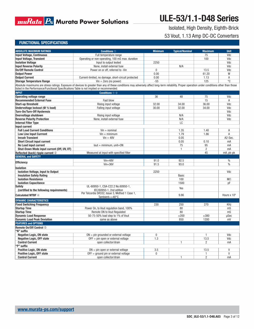
FUNCTIONAL SPECIFICATIONS
ABSOLUTE MAXIMUM RATINGS Conditions ➀ Minimum Typical/Nominal Maximum UnitInput Voltage, Continuous Full temperature range 75 VdcInput Voltage, Transient Operating or non-operating, 100 mS max. duration 100 VdcIsolation Voltage Input to output tested 2250 VdcInput Reverse Polarity None, install external fuse N/A VdcOn/Off Remote Control Power on or off, referred to -Vin 0 13.5 VdcOutput Power 0.00 61.20 WOutput Current Current-limited, no damage, short-circuit protected 0.00 1.13 AStorage Temperature Range Vin = Zero (no power) -55 125 °CAbsolute maximums are stress ratings. Exposure of devices to greater than any of these conditions may adversely affect long-term reliability. Proper operation under conditions other than those listed in the Performance/Functional Specifications Table is not implied or recommended.INPUT Conditions ➀ ➁Operating voltage range 36 48 75 VdcRecommended External Fuse Fast blow 15 AStart-up threshold Rising input voltage 32.00 34.00 36.00 VdcUndervoltage lockout (@ ½ load) Falling input voltage 30.00 32.00 34.00 VdcTurn-On/Turn-Off Hysteresis VdcOvervoltage shutdown Rising input voltage N/A VdcReverse Polarity Protection None, install external fuse N/A VdcInternal Filter Type LCInput current
Full Load Current Conditions Vin = nominal 1.35 1.40 ALow Line Input Currrent Vin = minimum 1.79 1.86 AInrush Transient Vin = 48V 0.05 A2-Sec.Short Circuit input current 0.05 0.10 mANo Load input current Iout = minimum, unit=ON 75 95 mAShut-Down Mode input current (Off, UV, OT) 1 2 mA
Reflected (back) ripple current ➁ Measured at input with specified filter 45 mA, pk-pkGENERAL and SAFETY
DYNAMIC CHARACTERISTICSFixed Switching Frequency 230 250 270 KHzStartup Time Power On, to Vout regulation band, 100% 80 mSStartup Time Remote ON to Vout Regulated 80 mSDynamic Load Response 50-75-50% load step to 1% of Vout ±200 ±380 µSecDynamic Load Peak Deviation same as above 850 1200 mVFEATURES and OPTIONSRemote On/Off Control ➄“N” suffix
Negative Logic, ON state ON = pin grounded or external voltage 0 1 VdcNegative Logic, OFF state OFF = pin open or external voltage 1.3 13.5 VdcControl Current open collector/drain 1 2 mA
“P” suffixPositive Logic, ON state ON = pin open or external voltage 3.5 13.5 VPositive Logic, OFF state OFF = ground pin or external voltage 0 1 VControl Current open collector/drain 1 2 mA
www.murata-ps.com/support
ULE-53/1.1-D48 SeriesIsolated, High Density, Eighth-Brick
53 Vout, 1.13 Amp DC-DC Converters
SDC_ULE-53/1.1-D48.A03 Page 4 of 12
OUTPUT Conditions ➀ Minimum Typical/Nominal Maximum UnitsTotal Output Power 0.00 60 WVoltage
Nominal Output Voltage 51.940 53.00 54.060 VdcSetting Accuracy At 50% load 2 % of Vout.nomOvervoltage Protection 59.5 Vdc
CurrentOutput Current Range 0.00 1.13 1.13 AMinimum Load no minimal load requiredCurrent Limit Inception 98% of Vout.min., after warmup 1.60 2.10 2.80 A
Short Circuit ➅
Short Circuit CurrentHiccup technique, autorecovery within ±1.25%
of Vout0.5 A
Short Circuit Duration (remove short for recovery) Output shorted to ground, no damage CONTINUOUS
Short circuit protection method Hiccup current limitingRegulation
Line Regulation Vin=min. to max., Vout=nom., full load ±0.5 % of VoutLoad Regulation Iout=min. to max., Vin=nom. ±3.6 % of Vout
Ripple and Noise Tested with eight 47µF ceramic caps in parallel 640 750 mV pk-pkTemperature Coefficient At all outputs 0.02 % of Vout./°CMaximum Capacitive Loading Low ESR 470 μFMinimum Capacitive Loading Low ESR 100 μFMECHANICAL (Through Hole Models) Conditions ➀➂ Minimum Typical/Nominal Maximum UnitsOutline Dimensions 0.89 x 2.22 x 0.39 Inches
(Please refer to outline drawing) 22.61 x 56.39 x 9.9 mmWeight 0.7 Ounces
1.524 & 1.016 mmThrough Hole Pin MaterialTH Pin Plating Metal and Thickness Nickel subplate µ-inches
Gold overplate µ-inchesENVIRONMENTALOperating Ambient Temperature Range See derating curves -40 85 °CStorage Temperature Vin = Zero (no power) -55 125 °CThermal Protection/Shutdown 125 °CElectromagnetic Interference External filter is required
Conducted, EN55022/CISPR22 B ClassRoHS rating RoHS 6/6
FUNCTIONAL SPECIFICATIONS, CONTINUED
1. The ULE-53/1.1-D48 is tested and specified with external 1||10 µF ceramic/tanta-lum output capacitors and a 22 µF external input capacitor. All capacitors are low ESR types. These capacitors are necessary to accommodate our test equipment and may not be required to achieve specified performance in your applications. General conditions for Specifications are +25 deg.C, Vin=nominal, Vout=nominal, full load. Adequate airflow must be supplied for extended testing under power.
2. Input Ripple Current is tested and specified over a 5 Hz to 20 MHz bandwidth. Input filtering is Cin=33 µF tantalum, Cbus=220 µF electrolytic, Lbus=12 µH.
3. Note that Maximum Power Derating curves indicate an average current at nominal input voltage. At higher temperatures and/or lower airflow, the DC-DC converter will tolerate brief full current outputs if the total RMS current over time does not exceed the Derating curve. All Derating curves are presented at sea level altitude. Be aware of reduced power dissipation with increasing density altitude.
4. Mean Time Before Failure is calculated using the Telcordia (Belcore) SR-332 Issue 3, Method 1 Case 1, Tpcboard=+40ºC, full output load, natural air convection.
5. The On/Off Control is normally controlled by a switch. But it may also be driven with external logic or by applying appropriate external voltages which are referenced to Input Common. The On/Off Control Input should use either an open collector or open drain transistor.
6. Short circuit shutdown begins when the output voltage degrades approximately 2% from the selected setting.
FUNCTIONAL SPECIFICATION NOTES
www.murata-ps.com/support
TYPICAL PERFORMANCE CURVES
70
72
74
76
78
80
82
84
86
88
90
92
0.10 0.22 0.33 0.45 0.56 0.68 0.79 0.91 1.02 1.1
ULE-53/1.1-D48 Efficiency vs. Line Voltage and Load Current @ +25°C
Load Current (Amps)
Effic
ienc
y (%
)
VIN = 60V
VIN = 48VVIN = 36V
VIN = 75V
1
2
3
4
5
6
7
0.1 0.2 0.3 0.4 0.6 0.7 0.8 0.9 1.0 1.1
ULE-53/1.1-D48 Power Dissipation vs. Load Current @ +25°C
Load Current (Amps)
Pow
er D
issi
patio
n (W
atts
)
VIN = 75VVIN = 60VVIN = 48VVIN = 36V
0 20 40 60 80 100 120
1.1
1.0
0.75
0.5
0.25
0
Outp
ut C
urre
nt (A
mps
)
Ambient Temperature (°C)
Natural convection
100 lfm
ULE-53/1.1-D48 Maximum Current Temperature Derating at sea level
ULE-53/1.1-D48 SeriesIsolated, High Density, Eighth-Brick
53 Vout, 1.13 Amp DC-DC Converters
SDC_ULE-53/1.1-D48.A03 Page 5 of 12
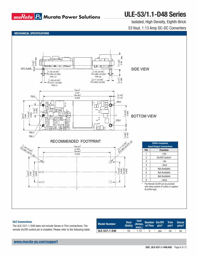
PHYSICAL CHARACTERISTICS AND SAFETYOutline dimensions See mechanical specs (below)
Pin material Copper alloy
Pin diameter 0.04/0.062" (1.016/1.524mm)
Pin finish Nickel underplate with gold overplate
Weight 1 ounce (28 grams)
Electromagnetic interference (external filter required) Designed to meet EN55022/CISPR22 with external filter
ULE-53/1.1-D48 SeriesIsolated, High Density, Eighth-Brick
53 Vout, 1.13 Amp DC-DC Converters
SDC_ULE-53/1.1-D48.A03 Page 6 of 12
ULE ConnectionsThe ULE-53/1.1-D48 does not include Sense or Trim connections. The remote On/Off control pin is installed. Please refer to the following table:
Model Number Vout(Volts)
Iout(Amps, max.)
Numberof Pins
On/Offpin?
Trimpin?
Sensepins?
ULE-53/1.1-D48 53 1.13 5 yes no no
MECHANICAL SPECIFICATIONS
DOSA-CompliantInput/Output Connections
Pin Function1 +Vin
2 On/Off Control*
3 −Vin
4 −Vout
5 Not Available
6 Not Available
7 Not Available
8 +Vout
* The Remote On/Off can be provided with either positive (P suffix) or negative (N suffix) logic.
50.802.000
56.42.22
7.
620.
300
15
.24
0.60
0
22
.60.
89
15
.24
0.60
0
2.79
0.110
3.
680.
145
58.422.300
22
.86
0.90
0
1.55 ±0.250.061 ±0.01 3X
50.802.000
15
.24
0.60
0
2.11 ±
0.25
0.083
±0.010
2X
15
.24
0.60
0
22
.90.
90
CL
CL
PIN 1
PIN 2
PIN 2
PIN 4
PIN 8
CL
RECOMMENDED FOOTPRINT
1.02 ±0.050.040 ±0.002
PIN 1-3
1.52 ±0.050.060 ±0.002
PIN 4,82.11 ±0.050.083 ±0.002
11.3
80.
45 M
ax
4.77
0.18
8
1.80 ±0.050.071 ±0.002
PIN1-3
0.25
0.01
0 M
in
MFG PLANE
1
2
3 4
8
SIDE VIEW
BOTTOM VIEW
www.murata-ps.com/support
ULE-53/1.1-D48 SeriesIsolated, High Density, Eighth-Brick
53 Vout, 1.13 Amp DC-DC Converters
SDC_ULE-53/1.1-D48.A03 Page 7 of 12
SHIPPING TRAYS AND BOXES
SHIPPING TRAY
ULE modules are supplied in a 21-piece (3-by-7) shipping tray. The tray is an anti-static closed-cell polyethylene foam. Dimensions are shown below.
Anti-static foam
Label Label
For 1–42 pc quantity For 43–84 pc quantity
7.800(198.1)
1.06(26.9)
2.400 (61) TYP
9.920(252)
0.625 (15.9) TYP
-0.062+0.000
1.300 (33.0) TYP0.25 CHAMFER TYP (4-PL)
Dimensions in inches (mm)
0.25 R TYP
9.920(252) +0.000
-0.062
0.735 (18.7)
0.455 (11.6) TYP
0.910 (23.1) TYP
www.murata-ps.com/support
TECHNICAL NOTES
Input FusingCertain applications and/or safety agencies may require the installation of fuses at the inputs of power conversion components. Fuses should also be used if the possibility of sustained, non-current-limited, input-voltage polarity reversals exist. For Murata Power Solutions ULE 60 Watt DC-DC Converters, you should use fast-blow type fuses, installed in the ungrounded input supply line, with values no greater than the following.
Model Fuse Values 48 Volt Input 4 Amps
All relevant national and international safety standards and regulations must be observed by the installer. For system safety agency approvals, the convert-ers must be installed in compliance with the requirements of the end-use safety standard.
Input Undervoltage Shutdown and Start-Up ThresholdUnder normal start-up conditions, devices will not begin to regulate until the ramping-up input voltage exceeds the Start-Up Threshold Voltage. Once operating, devices will not turn off until the input voltage drops below the Undervoltage Shutdown limit. Subsequent re-start will not occur until the input is brought back up to the Start-Up Threshold. This built in hysteresis prevents any unstable on/off situations from occurring at a single input voltage.
Start-Up TimeThe VIN to VOUT Start-Up Time is the interval of time between the point at which the ramping input voltage crosses the Start-Up Threshold and the fully loaded output voltage enters and remains within its specified accuracy band. Actual measured times will vary with input source impedance, external input/output capacitance, and load. The ULE Series implements a soft start circuit that limits the duty cycle of its PWM controller at power up, thereby limiting the input inrush current.
The On/Off Control to VOUT start-up time assumes the converter has its nominal input voltage applied but is turned off via the On/Off Control pin. The specification defines the interval between the point at which the converter is turned on and the fully loaded output voltage enters and remains within its specified accuracy band. Similar to the VIN to VOUT start-up, the On/Off Control to VOUT start-up time is also governed by the internal soft start circuitry and
external load capacitance.
The difference in start up time from VIN to VOUT and from On/Off Control to VOUT is therefore insignificant.
Input Source ImpedanceULE converters must be driven from a low ac-impedance input source. The DC-DC’s performance and stability can be compromised by the use of highly inductive source impedances. The input circuit shown in Figure 2 is a practical solution that can be used to minimize the effects of inductance in the input traces. For optimum performance, components should be mounted close to the DC-DC converter. If the application has a high source impedance, low VIN models can benefit of increased external input capacitance.
I/O Filtering, Input Ripple Current, and Output NoiseThe ULE-53/1.1-D48 is tested/specified for input reflected ripple current and output noise using the specified external input/output components/circuits and layout as shown in the following two figures.
External input capacitors (CIN in Figure 2) serve primarily as energy-storage elements, minimizing line voltage variations caused by transient IR drops in conductors from backplane to the DC-DC. Input caps should be selected for bulk capacitance (at appropriate frequencies), low ESR, and high rms-ripple-current ratings. The switching nature of DC-DC converters requires that dc voltage sources have low ac impedance as highly inductive source impedance can affect system stability. In Figure 2, CBUS and LBUS simulate a typical dc voltage bus. Your specific system configuration may necessitate additional considerations.
ULE-53/1.1-D48 SeriesIsolated, High Density, Eighth-Brick
53 Vout, 1.13 Amp DC-DC Converters
SDC_ULE-53/1.1-D48.A03 Page 8 of 12
www.murata-ps.com/support
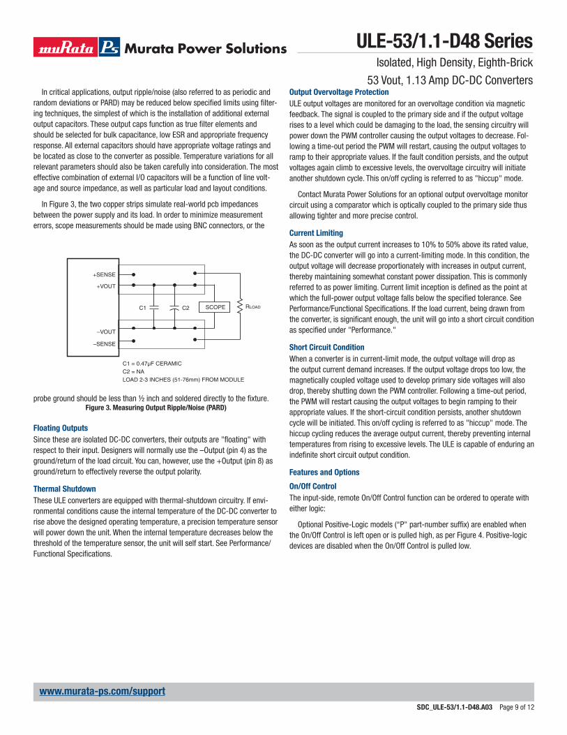
In critical applications, output ripple/noise (also referred to as periodic and random deviations or PARD) may be reduced below specified limits using filter-ing techniques, the simplest of which is the installation of additional external output capacitors. These output caps function as true filter elements and should be selected for bulk capacitance, low ESR and appropriate frequency response. All external capacitors should have appropriate voltage ratings and be located as close to the converter as possible. Temperature variations for all relevant parameters should also be taken carefully into consideration. The most effective combination of external I/O capacitors will be a function of line volt-age and source impedance, as well as particular load and layout conditions.
In Figure 3, the two copper strips simulate real-world pcb impedances between the power supply and its load. In order to minimize measurement errors, scope measurements should be made using BNC connectors, or the
Output Overvoltage ProtectionULE output voltages are monitored for an overvoltage condition via magnetic feedback. The signal is coupled to the primary side and if the output voltage rises to a level which could be damaging to the load, the sensing circuitry will power down the PWM controller causing the output voltages to decrease. Fol-lowing a time-out period the PWM will restart, causing the output voltages to ramp to their appropriate values. If the fault condition persists, and the output voltages again climb to excessive levels, the overvoltage circuitry will initiate another shutdown cycle. This on/off cycling is referred to as "hiccup" mode.
Contact Murata Power Solutions for an optional output overvoltage monitor circuit using a comparator which is optically coupled to the primary side thus allowing tighter and more precise control.
Current LimitingAs soon as the output current increases to 10% to 50% above its rated value, the DC-DC converter will go into a current-limiting mode. In this condition, the output voltage will decrease proportionately with increases in output current, thereby maintaining somewhat constant power dissipation. This is commonly referred to as power limiting. Current limit inception is defined as the point at which the full-power output voltage falls below the specified tolerance. See Performance/Functional Specifications. If the load current, being drawn from the converter, is significant enough, the unit will go into a short circuit condition as specified under "Performance."
Short Circuit ConditionWhen a converter is in current-limit mode, the output voltage will drop as the output current demand increases. If the output voltage drops too low, the magnetically coupled voltage used to develop primary side voltages will also drop, thereby shutting down the PWM controller. Following a time-out period, the PWM will restart causing the output voltages to begin ramping to their appropriate values. If the short-circuit condition persists, another shutdown cycle will be initiated. This on/off cycling is referred to as "hiccup" mode. The hiccup cycling reduces the average output current, thereby preventing internal temperatures from rising to excessive levels. The ULE is capable of enduring an indefinite short circuit output condition.
Features and Options
On/Off ControlThe input-side, remote On/Off Control function can be ordered to operate with either logic:
Optional Positive-Logic models (“P" part-number suffix) are enabled when the On/Off Control is left open or is pulled high, as per Figure 4. Positive-logic devices are disabled when the On/Off Control is pulled low.
probe ground should be less than ½ inch and soldered directly to the fixture. Figure 3. Measuring Output Ripple/Noise (PARD)
Floating OutputsSince these are isolated DC-DC converters, their outputs are "floating" with respect to their input. Designers will normally use the –Output (pin 4) as the ground/return of the load circuit. You can, however, use the +Output (pin 8) as ground/return to effectively reverse the output polarity.
Thermal ShutdownThese ULE converters are equipped with thermal-shutdown circuitry. If envi-ronmental conditions cause the internal temperature of the DC-DC converter to rise above the designed operating temperature, a precision temperature sensor will power down the unit. When the internal temperature decreases below the threshold of the temperature sensor, the unit will self start. See Performance/Functional Specifications.
ULE-53/1.1-D48 SeriesIsolated, High Density, Eighth-Brick
53 Vout, 1.13 Amp DC-DC Converters
SDC_ULE-53/1.1-D48.A03 Page 9 of 12
www.murata-ps.com/support
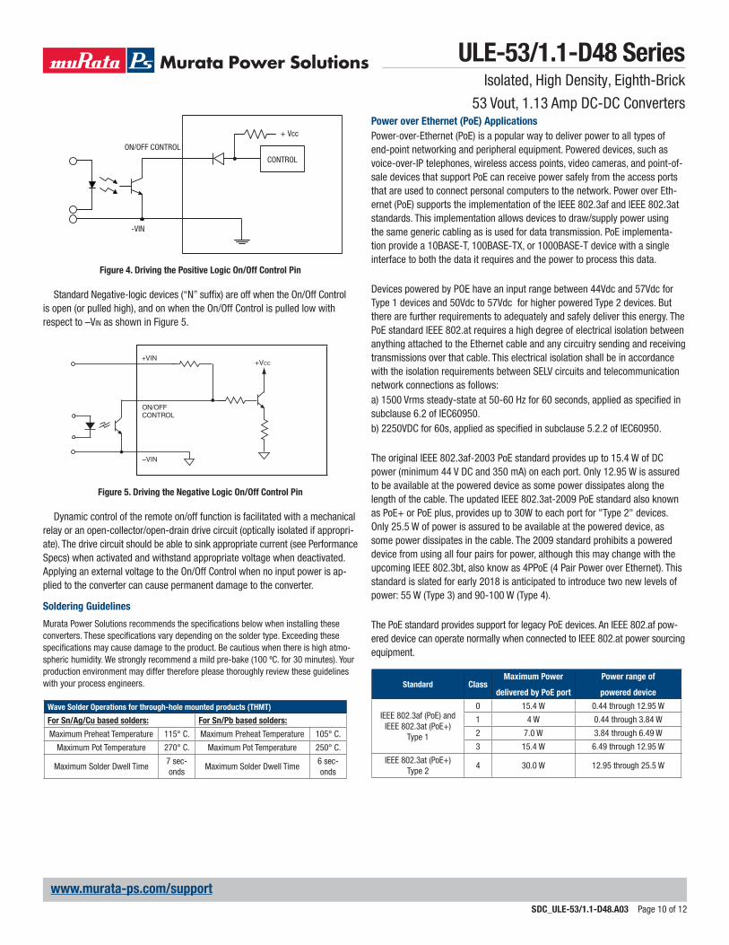
Figure 4. Driving the Positive Logic On/Off Control Pin
Standard Negative-logic devices (“N” suffix) are off when the On/Off Control is open (or pulled high), and on when the On/Off Control is pulled low with respect to –Vin as shown in Figure 5.
Figure 5. Driving the Negative Logic On/Off Control Pin
Dynamic control of the remote on/off function is facilitated with a mechanical relay or an open-collector/open-drain drive circuit (optically isolated if appropri-ate). The drive circuit should be able to sink appropriate current (see Performance Specs) when activated and withstand appropriate voltage when deactivated. Applying an external voltage to the On/Off Control when no input power is ap-plied to the converter can cause permanent damage to the converter.
ON/OFF CONTROL
CONTROL
+ Vcc
-VIN
+ VIN+VCC
–VIN
O N /O F F C O N TR O L
Wave Solder Operations for through-hole mounted products (THMT)
For Sn/Ag/Cu based solders: For Sn/Pb based solders:
Maximum Preheat Temperature 115° C. Maximum Preheat Temperature 105° C.
Maximum Pot Temperature 270° C. Maximum Pot Temperature 250° C.
Maximum Solder Dwell Time7 sec-onds
Maximum Solder Dwell Time6 sec-onds
Soldering Guidelines
Murata Power Solutions recommends the specifications below when installing these converters. These specifications vary depending on the solder type. Exceeding these specifications may cause damage to the product. Be cautious when there is high atmo-spheric humidity. We strongly recommend a mild pre-bake (100 ºC. for 30 minutes). Your production environment may differ therefore please thoroughly review these guidelines with your process engineers. Standard Class
Maximum Power
delivered by PoE port
Power range of
powered device
IEEE 802.3af (PoE) and IEEE 802.3at (PoE+)
Type 1
0 15.4 W 0.44 through 12.95 W
1 4 W 0.44 through 3.84 W
2 7.0 W 3.84 through 6.49 W
3 15.4 W 6.49 through 12.95 W
IEEE 802.3at (PoE+) Type 2
4 30.0 W 12.95 through 25.5 W
Power over Ethernet (PoE) ApplicationsPower-over-Ethernet (PoE) is a popular way to deliver power to all types of end-point networking and peripheral equipment. Powered devices, such as voice-over-IP telephones, wireless access points, video cameras, and point-of-sale devices that support PoE can receive power safely from the access ports that are used to connect personal computers to the network. Power over Eth-ernet (PoE) supports the implementation of the IEEE 802.3af and IEEE 802.3at standards. This implementation allows devices to draw/supply power using the same generic cabling as is used for data transmission. PoE implementa-tion provide a 10BASE-T, 100BASE-TX, or 1000BASE-T device with a single interface to both the data it requires and the power to process this data.
Devices powered by POE have an input range between 44Vdc and 57Vdc for Type 1 devices and 50Vdc to 57Vdc for higher powered Type 2 devices. But there are further requirements to adequately and safely deliver this energy. The PoE standard IEEE 802.at requires a high degree of electrical isolation between anything attached to the Ethernet cable and any circuitry sending and receiving transmissions over that cable. This electrical isolation shall be in accordance with the isolation requirements between SELV circuits and telecommunication network connections as follows:a) 1500 Vrms steady-state at 50-60 Hz for 60 seconds, applied as specified in subclause 6.2 of IEC60950. b) 2250VDC for 60s, applied as specified in subclause 5.2.2 of IEC60950.
The original IEEE 802.3af-2003 PoE standard provides up to 15.4 W of DC power (minimum 44 V DC and 350 mA) on each port. Only 12.95 W is assured to be available at the powered device as some power dissipates along the length of the cable. The updated IEEE 802.3at-2009 PoE standard also known as PoE+ or PoE plus, provides up to 30W to each port for "Type 2" devices. Only 25.5 W of power is assured to be available at the powered device, as some power dissipates in the cable. The 2009 standard prohibits a powered device from using all four pairs for power, although this may change with the upcoming IEEE 802.3bt, also know as 4PPoE (4 Pair Power over Ethernet). This standard is slated for early 2018 is anticipated to introduce two new levels of power: 55 W (Type 3) and 90-100 W (Type 4). The PoE standard provides support for legacy PoE devices. An IEEE 802.af pow-ered device can operate normally when connected to IEEE 802.at power sourcing equipment.
ULE-53/1.1-D48 SeriesIsolated, High Density, Eighth-Brick
53 Vout, 1.13 Amp DC-DC Converters
SDC_ULE-53/1.1-D48.A03 Page 10 of 12
www.murata-ps.com/support
Typical PSE(Power Sourcing Equipment) ApplicationULE-53/1.1-D48 series products can be used together with PSE controllers from various vendors, to provide reliable power in Endpoint or Midspan PSE. A typical application for PSE is shown below.
External FilteringThe specification for power feeding ripple and noise show below is required for common-mode and/or pair-to-pair static noise values for power outputs at the external port. The limits are meant to preserve data integrity. To meet EMI standards, lower values may be needed.
Power Supply115/230VAC36-72VDCout
ULE-53/1.1-D4836-72VDCin53VDCout
PoECircuitry
Ethernet &PoE Signals
Ethernet Signals
PoE Midspan Configuration
Power Feeding Ripple and Noise Type Max Unit
f < 500 Hz 1,2 0.500 Vpp
500 Hz to 150 kHz 0.200 1,2 0.200 Vpp
150 kHz to 500 kHz 0.150 1,2 0.150 Vpp
500 kHz to 1 MHz 1,2 0.100 Vpp
Power Supply115/230VAC36-72VDCout
ULE-53/1.1-D4836-72VDCin53VDCout
PoECircuitry
Ethernet &PoE Signals
Ethernet Signals
PoE Endspan Configuration
Figure 6. Typical Application for PSEBasic PSEThe PSE is kind of a power switch, controlling the PoE process described hereafter. As such, it holds the PoE "intelligence", therefore a CPU is required to control the PoE process while other analog components are doing the switch-ing, sensing and power filtering activities.
Endspan and MidspanThere are two basic types of PSE: Endspan and Midspan. Endspan PSE inte-grates PoE into Ethernet switches, while Midspan PSE is an element resides between the switch and the terminal, providing power only.
Endspans are mainly for green-field installations. Midspan devices, on the other hand, are for organizations looking to upgrade a network without replac-ing existing switches.
The Endspan is a switch that integrates the PoE source, to simplify the infra-structure, using "Phantom Feeding" on the center tap of the Ethernet pulse transformer. 802.3af allows the Endspan to use the spare pairs for power delivery instead of the data pairs, though the latter configuration is more com-monly used.
The Midspan is a patch panel like device that receives data lines from the switch and inserts power over the spare pairs, providing data and power out to the PD (Powered Devices)
Basic PD(Powered Devices)802.3af defines a PD as a device that is either drawing power or requesting power from a PSE. The PD can be one of many different devices, including IP phone, wireless LAN access point, security network camera and other Ethernet terminals. Power can enter the PD with either polarity on data pairs (1/2 and 3/6) or on spare pairs (4/5 and 7/8). The data interface is a standard line transformer, with center tap on the primary that faces the RJ-45 jack. Data flows through the transformers to Ethernet PHY. The 48 Vdc power is extracted from the center taps and passes through a PoE interface block that acts as an intelligent switch.
ULE-53/1.1-D48 SeriesIsolated, High Density, Eighth-Brick
Murata Power Solutions, Inc. 11 Cabot Boulevard, Mansfield, MA 02048-1151 U.S.A.ISO 9001 and 14001 REGISTERED
This product is subject to the following operating requirements and the Life and Safety Critical Application Sales Policy: Refer to: http://www.murata-ps.com/requirements/
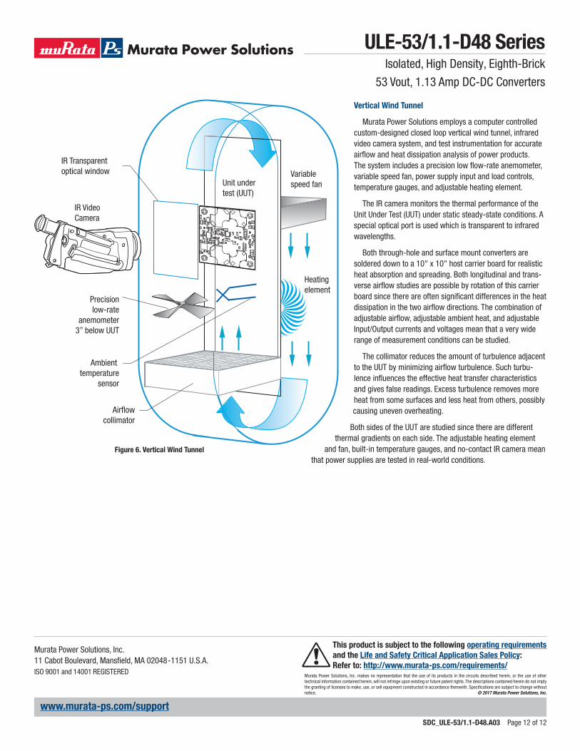
Figure 6. Vertical Wind Tunnel
IR Video Camera
IR Transparentoptical window Variable
speed fan
Heating element
Ambient temperature
sensor
Airflowcollimator
Precisionlow-rate
anemometer3” below UUT
Unit undertest (UUT)
Vertical Wind Tunnel
Murata Power Solutions employs a computer controlled custom-designed closed loop vertical wind tunnel, infrared video camera system, and test instrumentation for accurate airflow and heat dissipation analysis of power products. The system includes a precision low flow-rate anemometer, variable speed fan, power supply input and load controls, temperature gauges, and adjustable heating element.
The IR camera monitors the thermal performance of the Unit Under Test (UUT) under static steady-state conditions. A special optical port is used which is transparent to infrared wavelengths.
Both through-hole and surface mount converters are soldered down to a 10" x 10" host carrier board for realistic heat absorption and spreading. Both longitudinal and trans-verse airflow studies are possible by rotation of this carrier board since there are often significant differences in the heat dissipation in the two airflow directions. The combination of adjustable airflow, adjustable ambient heat, and adjustable Input/Output currents and voltages mean that a very wide range of measurement conditions can be studied.
The collimator reduces the amount of turbulence adjacent to the UUT by minimizing airflow turbulence. Such turbu-lence influences the effective heat transfer characteristics and gives false readings. Excess turbulence removes more heat from some surfaces and less heat from others, possibly causing uneven overheating.
Both sides of the UUT are studied since there are different thermal gradients on each side. The adjustable heating element
and fan, built-in temperature gauges, and no-contact IR camera mean that power supplies are tested in real-world conditions.
ULE-53/1.1-D48 SeriesIsolated, High Density, Eighth-Brick


![THE REVOLUTION IN RALLY BRAKING RACING BRAKE ......RALLY, SPRINT AND STOCK CAR RACING BRAKE PADS Make / Type Thickness Pad Shape No. H type [4463] D40 / D44 / D48 CP2340 D40 / D48](https://static.documents.pub/doc/80x56/60690b09d4fdff21fb2e631b/the-revolution-in-rally-braking-racing-brake-rally-sprint-and-stock-car.jpg)


![ViX Series - Micromech · in the global industrial market. ... advanced operations such as external encoder following and registration ... Capacitance power module [µF] 3300 6600](https://static.documents.pub/doc/80x56/5b08adb97f8b9a3d018c8891/vix-series-the-global-industrial-market-advanced-operations-such-as-external.jpg)


