238
/GALA_Documents/DD-036 Project GALA_Documents Performance Budget File Version: 3.1 Printed by: GALA_Administrator Printed on: 08 December 2000 Generated from DOORS 5.0
/GALA_Documents/DD-036
Project GALA_Documents
Performance Budget File
Version: 3.1
Printed by: GALA_Administrator
Printed on: 08 December 2000
Generated from DOORS 5.0

Contents
1 4INTRODUCTION
1.1 4Scope of the document1.2 5Organization of the document
2 7REFERENCES
2.1 7Definitions2.1.1 7Accuracy (NSE(95%))2.1.2 7Integrity
2.1.2.1 7Integrity Risk2.1.2.2 7Alarm limit2.1.2.3 7System Time to Alert2.1.2.4 8(Horizontal-vertical) Protection level
2.1.3 8Continuity Of Service2.1.4 8Availability of service
2.2 8Acronyms2.3 8Reference document
3 10GALILEO constellation Performance definitions andassumptions
3.1 10Constellation geometry assumptions3.2 10Satellite RAMS figures3.3 12Orbit and synchronisation residual error
4 13GALILEO Navigation performance Allocation
4.1 13Overall Approach4.2 14Galileo Mission Requirements4.3 16Architecture Identification
4.4 17Allocation with other sytems4.5 18Accuracy4.6 18Global Navigation Function Only services
4.6.1 18Performance Allocation for OAS-G1 & 24.6.2 19Integrity Performance Allocation for SAS-G/En Route4.6.3 23Continuity Performance Allocation for SAS-G/En Route4.6.4 24Availability Performance Allocation for SAS-G/En Route
4.7 25Global Navigation Function + Global Integrity Function4.7.1 25Integrity Performance Allocation for CAS1-G
4.7.1.1 25GIC and RAIM allocation4.7.1.1.1 26Option 1: Serial Allocation4.7.1.1.2 26Option 2: Parallel Allocation4.7.1.1.3 28User Integrity Risk Allocation tree
4.7.1.2 30Integrity Risk Allocation within Global component4.7.1.3 32Time To Alarm Allocation
4.7.2 34Integrity Performance Allocation for CAS1-GS 4.7.3 35Integrity Performance Allocation for SAS/NPA4.7.4 36Integrity Performance Allocation for SAS-G/Cat 14.7.5 39Integrity Performance Allocation for SAS-GS/Cat14.7.6 39Integrity Performance Allocation for GAS-G4.7.7 40Integrity performance allocation for GAS-GS service4.7.8 41Continuity Performance Allocation for CAS1-G4.7.9 42Continuity performance allocation for CAS1-GS service
4.7.10 43Continuity Performance Allocation for SAS-G/NPA4.7.11 45Continuity Performance Allocation for SAS-G/Cat14.7.12 47Continuity Performance Allocation for SAS-GS/Cat14.7.13 47Continuity Performance Allocation for GAS-G4.7.14 48Continuity Performance Allocation for GAS-GS4.7.15 48Availability Performance Allocation for CAS1-G service4.7.16 50Availability Performance Allocation for CAS1-GS service
Contents i

4.7.17 51Availability Performance Allocation for SAS-G/NPAservice
4.7.18 52Availability Performance Allocation for SAS-G/Cat1service
4.7.19 52Availability Performance Allocation for SAS-GS/Cat1service
4.7.20 53Availability Performance Allocation for GAS-G service4.7.21 54Availability Performance Allocation for GAS-GS service
4.8 54Global Navigation Function + Regional IntegrityFunction
4.8.1 54SAS-R service provision4.8.2 56Integrity Performance Allocation for SAS-R service4.8.3 58Integrity performance allocation for SAS-RM service 4.8.4 58Continuity Performance Allocation for SAS-R4.8.5 61Continuity performance allocation for SAS-RM4.8.6 61Availability Performance Allocation for SAS-R 4.8.7 63Availability performance allocation for SAS-RM service4.8.8 64EGNOS service provision
4.9 64Global Navigation functions + Local functions4.9.1 65Integrity Performance Allocation for CAS1-L14.9.2 68Integrity performance allocation for SAS-L service 4.9.3 68Integrity performance allocation for GAS-L service 4.9.4 69Continuity Performance Allocation for CAS1-L service4.9.5 70Continuity Performance Allocation for SAS-L service4.9.6 70Continuity Performance Allocation for GAS-L service4.9.7 71Availability Performance Allocation for CAS1-L service4.9.8 72Availability Performance Allocation for SAS-L service4.9.9 73Availability Performance Allocation for SAS-L service4.10 73From Mission to System Requirements
5 77UERE budget
5.1 77Scenario definition 5.1.1 77System Specific Parameters
5.1.1.1 77Galileo services5.1.1.2 78System Architecture
5.1.2 79User Specific Parameters 5.1.3 80Signal Structure Hypothesis
5.2 81Dual L band frequency UERE with SAS/GAS receiverassumption
5.2.1 81UERE budget error in GLOBAL5.2.1.1 81Signal to Noise ratio
5.2.1.1.1 81Signal power5.2.1.1.2 83User antenna gain5.2.1.1.3 84Receiver Thermal Noise5.2.1.1.4 85Galileo Cross Interference5.2.1.1.5 86External Interference5.2.1.1.6 88Signal to Noise Ratio
5.2.1.2 89Receiver Budget Error5.2.1.2.1 89Code Tracking Error5.2.1.2.2 91Multipath Budget Error 5.2.1.2.3 93Global Receiver Budget Error
5.2.1.3 94Tropospheric Residual Error5.2.1.4 96Total UERE after Dual Frequency Processing
5.2.1.4.1 97UERE with high multipath5.2.1.4.2 99UERE with low multipath
5.3 100Dual L band frequency UERE with OAS/CAS1 receiverassumption
5.3.1 100UERE budget error in GLOBAL5.3.1.1 100Multipath Budget Error 5.3.1.2 102Total UERE after Dual Frequency Processing
Contents ii

5.3.1.2.1 102Total UERE with high multipath5.3.1.2.2 104Total UERE with low multipath
5.4 105Single L band frequency UERE with OAS/CAS1 receiverassumptions
5.4.1 105Residual Ionospheric Error5.4.2 107Total UERE
5.5 108Single C band frequency UERE with SAS/GAS receiverassumptions
5.5.1 108UERE in Global5.5.1.1 108Multipath Budget Error5.5.1.2 109Ionospheric Budget Error5.5.1.3 110Total Budget Error
5.6 112UERE in Local5.6.1 112L band UERE budget with SAS/GAS receiver
assumptions5.6.1.1 112Receiver Budget Error
5.6.1.1.1 112Code measurements5.6.1.2 112Troposphere Budget Error5.6.1.3 114Ionosphere Budget Error5.6.1.4 115Total Budget Error
5.6.1.4.1 115Local UERE with high multipath5.6.1.4.2 116Local UERE with low multipath
5.6.2 117L band UERE budget with OAS/CAS1 receiverassumptions
5.6.2.1 118UERE in local with high multipath5.6.2.2 119UERE in local with low multipath
5.6.3 120C band UERE budget with SAS/GAS receiverassumptions
5.6.3.1 120UERE budget with high multipath5.6.3.2 122UERE budget with low multipath
5.7 122UERE Recapitulative
5.7.1 123GLOBAL UERE5.7.1.1 123High multipath5.7.1.2 124Low multipath
5.7.2 125LOCAL UERE5.7.2.1 125High multipath5.7.2.2 126Low multipath
6 128Performance budget
6.1 128Baseline simulations assumptions6.1.1 128Space segment6.1.2 128Receiver Assumptions
6.1.2.1 128Number of channels6.1.2.2 128Masking Angle6.1.2.3 128Navigation Algorithm6.1.2.4 129RAIM availability algorithm6.1.2.5 129GIC availability algorithm6.1.2.6 129RAIM GIC combination6.1.2.7 129Integrity allocation
6.1.3 129Ground Segment6.1.4 129Simulation assumptions
6.1.4.1 129Area6.1.4.2 130Simulation duration6.1.4.3 130Time sampling6.1.4.4 130Latitude sampling6.1.4.5 130Longitude sampling6.1.4.6 130Failures
6.1.5 130UERE budget6.1.6 130Urban Canyon Characterization
6.2 132Continuity preliminary assessment6.2.1 132SAS-G/NPA
Contents iii

6.2.2 138SAS-G/Cat16.3 138Availability assessment
6.3.1 139OAS Service 6.3.1.1 139OAS-G16.3.1.2 141OAS-G2
6.3.2 143CAS1 service6.3.2.1 143CAS1-G
6.3.2.1.1 143Accuracy performance6.3.2.1.2 143Integrity performance
6.3.2.2 146CAS1-L6.3.2.2.1 146Accuracy performance6.3.2.2.2 148Integrity performance
6.3.3 150SAS and GAS Services6.3.3.1 150SAS-G/En route
6.3.3.1.1 150Accuracy performance6.3.3.1.2 152Integrity performance
6.3.3.2 154SAS-G/NPA6.3.3.2.1 154Accuracy performance6.3.3.2.2 154Integrity performance
6.3.3.3 156SAS-G/Cat1 and GAS-G6.3.3.3.1 157Accuracy performance6.3.3.3.2 159Integrity performance
6.3.3.4 162SAS-R6.3.3.5 162SAS-L and GAS-L
6.3.3.5.1 163Accuracy performance6.3.3.5.2 165Integrity performance
6.3.4 167Sensitivity analysis6.3.4.1 167Sensitivity to the multipath error budget6.3.4.2 171Sensitivity to the user mask angle6.3.4.3 175Sensitivity to the horizontal / vertical allocation of the
integrity risk
6.3.4.4 178Sensitivity to the vertical alarm limit value6.3.4.5 180Sensitivity to the vertical accuracy requirement value
7 182Performance with External system
7.1 182Global Positioning System (GPS+)7.1.1 182Assumptions
7.1.1.1 182Constellation parameter7.1.1.1.1 182GPS constellation parameter
7.1.1.2 183UERE7.1.2 184Combined Galileo/GPS Navigation Performance
7.1.2.1 184Performance of GPS only7.1.2.2 186Baseline Availability of Service for combined use of GPS
and Galileo7.1.2.2.1 186OAS-GS7.1.2.2.2 188CAS1-GS
7.1.2.2.2.1 188Accuracy performance7.1.2.2.2.2 190Integrity performance
7.1.2.2.3 192SAS-GS/Cat1 and GAS-GS7.1.2.2.3.1 192Accuracy performance7.1.2.2.3.2 194Integrity performance
7.1.2.2.4 196SAS-RM7.1.2.3 200Sensitivity analysis of the availability for combined use of
Galileo and GPS7.1.2.3.1 200OAS-GS
7.1.2.3.1.1 200Sensitivity to the multipath level7.1.2.3.1.2 202Sensitivity to the requirement
7.1.2.3.2 203CAS1-GS7.1.2.3.2.1 204Sensitivity to the multipath level7.1.2.3.2.2 206Sensitivity to the requirement
7.1.2.3.3 210SAS-GS and GAS-GS
Contents iv

7.1.2.3.3.1 210Sensitivity to the multipath level and the user maskangle
7.1.2.3.3.2 212Sensitivity to the requirement7.2 214Loran C/ Eurofix
7.2.1 214Introduction7.2.2 215Loran C performance assumption7.2.3 216Combined Galileo/Loran C expected performance.
7.2.3.1 216Performance Allocation7.2.3.2 216Availability Performance in Urban canyon7.2.3.3 217Outage Characterization
7.2.3.3.1 217Mean number of satellites in visibility7.2.3.3.2 219satellites availability 7.2.3.3.3 221Horizontal Accuracy availability statistics
7.2.3.4 222Conclusion7.3 223Hybridization with other system
8 224Synthesis : Availability compliance matrix forGALILEO and Galileo+GPS services
9 227Conclusion And Open Points
9.1 227Open points and recommendation9.1.1 227Local effects characterization
9.1.1.1 227Multipath contribution in UERE budget9.1.1.2 227Multiple and single failure due to local effects 9.1.1.3 228Masking angle and Interference mask
9.1.2 228Allocation assumptions9.1.2.1 228RAMS analysis9.1.2.2 228Clock stability9.1.2.3 229Network reliability9.1.2.4 229Up-link capabilities with dynamic antennas
9.1.3 229Integrity concept
9.1.3.1 229Feasibility of the GIC concept9.1.3.2 230Integrity performance concept
9.1.4 230Model limitations9.1.4.1 230Integrity modeling9.1.4.2 230Availability modeling9.1.4.3 231Other sensor/ system simulation
9.2 231Conclusion
Contents v

DD-036 Page 1 of 232 Printed 08 December 2000
Index
1
2
20
ID
DD-036-1
DD-036-2
DD-036-3
Performance Budget File
DOCUMENT PRODUCTION
DOCUMENT DISTRIBUTION
From Stephane LANNELONGUE
Project Acronym GALA
Project Name Galileo Overall Architecture Definition
Title Performance Budget File
Issue 3.1
Reference GALA-ASPI-DD036
Date 08/12/00
Pages number 225
File GALA-ASPI-DD036v3.doc
Issue 3.1
Classification PU
WBS D34
Contract GALA-ASPI
Emitting Entity ALCATEL SPACE INDUSTRIES
Type of Document A
Status -
Template Name gala_aspi.dot (V1)
DOCUMENT ENDPAPER
Written by Responsibility - Company Date Signature
S. LANNELONGUEH. DELFOUR
ASPIASPI
Verified by

DD-036 Page 2 of 232 Printed 08 December 2000
Index
28
ID
DD-036-3663
Performance Budget File
JM PIEPLU ASPI
Approved
A. MASSON ASPI
CHANGE RECORDS
ISSUE DATE § : CHANGE RECORD AUTHOR
1A 03/03/00 First issue F AIGLE
1.1 05/05/00 MTR versionAll sections changed
S LANNELONGUE
2.0 20/07/00 PM4 versionAll sections changedConsolidation of the UEREProvision of performance allocation[Simulation results provided at MTR removedbecause no longer applicable]
S LANNELONGUE
2.1 31/07/00 Adjustment of mission requirementsparameter with DD09Alignment with DD31 for the performanceallocation
S. LANNELONGUE
3.a 10/08/00 Working version including final version ofPerformance allocation and UERE budget
S. LANNELONGUE
3.b 10/11/00 Working version.Addition of chapter 6 and 7 for performanceassessmentAddition of System requirement derivationmethod
H. DELFOURS. LANNELONGUE
3.0 20/11/00 Final version delivered for Final ReviewInclusion of comments coming from GALAinternal review process
H. DELFOURS. LANNELONGUE

DD-036 Page 3 of 232 Printed 08 December 2000
Index
40
41
42
ID
DD-036-4
DD-036-5
DD-036-6
Performance Budget File
3.1 08/12/00 Migration to DOORS JL DAMIDAUX
TABLE OF CONTENTS
INDEX OF TABLES
INDEX OF FIGURES
DD-036 Page 4 of 232 Printed 08 December 2000
Index
43
44
45
46
47
48
49
50
51
52
53
54
55
56
57
ID
DD-036-7
DD-036-8
DD-036-9
DD-036-10
DD-036-11
DD-036-12
DD-036-13
DD-036-14
DD-036-15
DD-036-16
DD-036-17
DD-036-18
DD-036-19
DD-036-20
DD-036-21
Performance Budget File
1 INTRODUCTION
1.1 Scope of the document
This document is the output of the work package 3.4 of GALA dealing with Galileo architecture performance assessment.
The main objective of this work package is to assess the feasibility of the required navigation system performance by means ofsimulations for the proposed architecture. The performance considered are:
- accuracy
- integrity
- continuity
- availability
First, mission requirements are allocated to the different component of Galileo which are namely:
- The global component
- The regional component
- The local component
- And the user terminal
Some of the services are planned to be provided with GPS. For such service an allocation of performance which is, in this case,closer to an a priori estimation of GPS is also provided.
Next, the UERE computations is detailed. Different class of users (or different class of services) are considered: OAS (OpenAccess Service), CAS1 (Control Access Service level 1) , CAS2/SAS (Safety critical service), CAS2/GAS (Governmental service).

DD-036 Page 5 of 232 Printed 08 December 2000
Index
58
59
60
61
62
63
64
65
66
67
ID
DD-036-22
DD-036-23
DD-036-24
DD-036-25
DD-036-26
DD-036-27
DD-036-28
DD-036-29
DD-036-30
DD-036-31
Performance Budget File
In a third step performance of Galileo with respect to the mission requirements is assessed. The performance are computed withhigh level models (global models to evaluate the system and to have sensitivity analyses rather than models of the actualalgorithms or functions, since many of them are not yet defined or stabilized). Assessment of the performance withhybridization and other systems is also performed. The other systems identified to be hybridized with Galileo components areGPS, Loran C and GNSS 1. GLONASS is not yet included since the future of this system within Galileo architecture dependsheavily of international negotiation.
One important thing to point out is that the detail design of the different component is not the task of GALA. Therefore, thisdocument does not pretend to make compliance statement between the Galileo architecture and the Galileo missionrequirements. On the contrary, the definition of the Galileo mission requirements is the task of GALA. Therefore, thisdocument aims at assessing the feasibility of the requirements making reasonable assumptions on the architecture in order toconsolidate them.
A first cost estimation shows that, as far as performance is concerned, the most critical component is the space segment. Therefore, the performance assessment part of this document will focus on the constellation performance. At the end, it is surethat the ground segment design will have a great impact on the final performance. However the cost of the system is drivenmainly by the constellation. Therefore for assessing feasibility, the ground segment will be assumed compliant to allocatedperformance requirements.
1.2 Organization of the document
This document aims at managing all information concerning Galileo final performance. It presents the performance budgetsand justifications associated to each service levels. It shall include trace-ability of the mission requirements to system andsubsystem requirements, a preliminary performance allocation and margins, justification of the compliance levels (experiments,analyses and simulation results).
The main outcomes of this document are
- [Chapter 4] Allocation of the top mission requirements to the different component of the system (global, regional, local,receiver, signal).
- [Chapter 5] UERE budget for different classes of user (OAS, CAS1, SAS and GAS)
- [Chapter 6] Performance assessment for Galileo only services
- [Chapter 7] Performance assessment of Galileo combined with other system such as GPS and Loran C

DD-036 Page 6 of 232 Printed 08 December 2000
Index
68
69
ID
DD-036-32
DD-036-33
Performance Budget File
- [Chapter 8] Galileo architecture “Compliance” to Mission Performance requirement
- [Chapter 9] Open points, recommendation and conclusion
DD-036 Page 7 of 232 Printed 08 December 2000
Index
70
71
72
73
74
75
76
77
78
79
80
81
82
ID
DD-036-34
DD-036-35
DD-036-36
DD-036-37
DD-036-38
DD-036-39
DD-036-40
DD-036-41
DD-036-42
DD-036-43
DD-036-44
DD-036-45
DD-036-46
Performance Budget File
2 REFERENCES
2.1 Definitions
Performance parameters are defined in the Definition document of GALA [RD-09]. The relevant ones for performanceestimation are recalled here after.
2.1.1 Accuracy (NSE(95%))
This is the value that bounds the “instantaneous” position error at a specific location and a specific time with a probability of kpercent not to be exceeded. This definition is usable as an accuracy definition. The NSE (Navigation System Error) will bespecified at 95 percent confidence level. This NSE parameter is the one used to declare at every space-time point the availabilityof the positioning service with required accuracy.
2.1.2 Integrity
2.1.2.1 Integrity Risk
This is the probability during the period of operation that an error, whatever is the source, might result in a computed positionerror exceeding a maximum allowed value, called Alarm Limit, and the user be not informed within the specific time to alarm.
2.1.2.2 Alarm limit
This is the maximum allowable error in the user position solution before an alarm is to be raised within the specific time toalarm. This alarm limit is dependent on the considered operation, and each user is responsible for determining its own integrityin regard of this limit for a given operation following the information provided by GALILEO SIS (Signal In Space). In thisdocument, we will refer to this definition by HAL (Horizontal Alarm Limit) and VAL (Vertical Alarm Limit), and XAL standingfor HAL or VAL.
2.1.2.3 System Time to Alert
The System time to alert is defined as the time starting when an alarm condition occurs to the time that the alarm is displayed atthe user interface. Time to detect the alarm condition is included as a component of this requirement.
Industry considers that start event of an alarm condition is the beginning of a sampling period, in the monitoring stationreceiver, during which an erroneous pseudo range will be received.

DD-036 Page 8 of 232 Printed 08 December 2000
Index
83
84
85
86
87
88
89
90
91
92
ID
DD-036-47
DD-036-48
DD-036-49
DD-036-50
DD-036-51
DD-036-52
DD-036-53
DD-036-54
DD-036-55
DD-036-56
Performance Budget File
2.1.2.4 (Horizontal-vertical) Protection level
This is the value computed by the user receiver which estimates the confidence bound on the actual Navigation System Errorusing data transmitted by the Galileo ground mission segment signal (e.g. SISA, differential corrections accuracy, …) and/orpre-determined bounds. The user integrity monitoring function is available when the protection level is computable and is lessthan the alarm limit. In this document, we will refer to this definition by HPL (Horizontal Protection Level) and VPL (VerticalProtection Level), and XPL standing for HPL or VPL.
The XPL value varies with the confidence required. This confidence is expressed in terms of false alarm and miss detectionprobabilities. Those parameters are sized according to the probability of failure of the system and the integrity risk required.
2.1.3 Continuity Of Service
Continuity of Navigation Service is defined as the probability that the accuracy and integrity requirements will be supported bythe Navigation System over the time interval applicable for a particular operation within the coverage area given that they aresupported at the beginning of the operation and that they are predicated to be supported all along the operation duration.Satellite outages predicted at least 48 hours in advance of the outage do not contribute to loss of continuity. This assumes thatan adequate notice is provided to the users. For civil Aviation this service is referred to as NOTAM (Notice to Airmen).
2.1.4 Availability of service
Availability of the Navigation Service is the probability that the Positioning service and the Integrity monitoring service areavailable and provide the required accuracy, integrity and continuity performances . The service will be declared available whenaccuracy and integrity requirements In practice, for integrity, we compute the availability of the UIM function (e.g. XPLavailability) are met at the beginning of an operation and are estimated to be met during all the operation period (= continuityrequirement).
2.2 Acronyms
See document Performance definition GALA-ASPI-DD092
2.3 Reference document
[RD-01] GALILEO Mission Requirements GALA-ASPI-DD108
[RD-02] GALILEO System Requirements GALA-ASPI-DD107

DD-036 Page 9 of 232 Printed 08 December 2000
Index ID Performance Budget File
[RD-03] Global component requirements GALA-ALS-DD31
[RD-04] Regional component requirements GALA-ALS-DD32
[RD-05] Local component requirements GALA-DSS-DD33
[RD-06] Galileo Constellation trade-offs GALA-ASPI-DD12
[RD-07] Galileo Integrity Trade-off GALA-ASPI-DD13
[RD-08] Galileo Architecture Baseline Definition GALA-ASPI-DD027.
[RD-09] GALA Performance Definition GALA-ASPI-DD092
[RD-10] GALA Architecture justification GALA-DSS-DD030
[RD-11] Use of Other Systems GALA-SC75-DD015
[RD-12] Use of Other Sensors GALA-SEXTANT-DD016
[RD-13] Galileo system and segments justification file GNSS2-P2-sys-501Issue 2B
[RD-14] MOPS for GPS/Wide Area Augmentation System Airborne Equipment,RTCA
[RD-15] Signal Design and Transmission Performance Study for GNSS
[RD-16] Global Positioning System, Theory and Application, James J. Spilker.
[RD-17] A modernization deployment strategy to meet military and civil needs,ION-GPS 1999, Nashville
[RD-18] FAA's plan for the future use of GPS, Sandhoo, Biggs, ION-GPS 1999,Nashville
[RD-19] MASPS (Draft) for local augmentation, RTCA

DD-036 Page 10 of 232 Printed 08 December 2000
Index
112
113
114
115
116
117
118
119
124
125
ID
DD-036-76
DD-036-77
DD-036-78
DD-036-79
DD-036-80
DD-036-81
DD-036-82
DD-036-96
DD-036-97
DD-036-98
Performance Budget File
3 GALILEO constellation Performance definitions and assumptions
3.1 Constellation geometry assumptions
Several options were considered for the constellation architecture:
- The 30 MEOs (Medium Earth Orbit) constellation
- The 27 MEOs + 3 active spares
- The 24 MEOs and 3 GEOs (Geo-stationary) constellation (3 GEO for regional service, for GLOBAL service 8 GEOs arenecessary)
The goal of this work package is not to compare those constellations. Optimization of the constellation orbital parameters is theresponsibility of GalileoSat study and furthermore within GALA project, WP2.2.1 (Constellation trades-off) is in charge ofcomparing constellation performance. The objective of this WP is to assess requirements feasibility. Therefore only the baselineconstellation is included in the scope of this work package. Due to the fact that the 27/3/1 constellation appears to be morerobust to satellite failures comparing to the 30/3/0, it has been selected as baseline in GalileoSat study. Therefore thisconstellation is used for performance estimation for the final version of this document. The orbital parameters of thisconstellation are gathered in the Table 1:
Table 1: Constellation parameters
Walker constellation 27/3/1
Altitude 23616 km
Inclination 56°
Eccentricity 0
3.2 Satellite RAMS figures
Preliminary results about satellites failures were provided during the Comparative System Study phase 2 (CSS2). Thoseconclusions are present in the justification file [RD-013] and are recalled here after. They will be used in the frame of GALA inorder to assess the Galileo performance. However, let us remind that it is not the role of GALA to define accurately the satellitereliability. The goal of this document is more to take reasonable assumptions to check that the performance requirements puton Galileo global component are feasible. The RAMS figure taken into account are detailed in the following Table:

DD-036 Page 11 of 232 Printed 08 December 2000
Index
131
132
133
134
135
136
137
ID
DD-036-117
DD-036-118
DD-036-119
DD-036-120
DD-036-121
DD-036-122
DD-036-145
Performance Budget File
MEO GEO
Manoeuvres MTBM = 365 daysMTTR = 3 hours
MTBM = 15 daysMTTR = 8 hours
Short termfailures
MTBF = 625 daysMTTR = 72 hours
Long term failures MTTR = 7 days (in-orbit spares)MTBF = 22.9 years
MTTR = 5 months (on-ground spares)MTBF = 22.9 years
MTTR= Mean Time To Repair, MTBF= Mean Time Between Failure
Table 2: Constellation RAMS figure
The following assumptions are used to compute the probability of state of the constellation:
In orbit spare available to cope for long terms failure
Maneuver what ever is the state of the constellation
By processing the above figures of satellite failures with a Markov process, the following state probabilities of the constellationcan be computed. Those probability have been computed considering that the satellite has a reliability law that follows anexponential curve.
Table 3: Probability of State of the Constellation
Number of satellites operational Probability of state
27 0.844
26 0.136
25 0.017
24 2.10E-03
23 2.41E-04
22 2.65E-05

DD-036 Page 12 of 232 Printed 08 December 2000
Index
145
146
147
148
ID
DD-036-146
DD-036-147
DD-036-148
DD-036-149
Performance Budget File
3.3 Orbit and synchronisation residual error
The trade off concerning the determination of orbit and clock characteristics of Galileo satellites has been addressed in theComparative System Study [RD-013]. For this investigation, which consider the different influence of H-maser and RAFS(Rubidium) clocks stability, it has been implemented an accurate algorithm for the Allan Variance clock model .
These analyses demonstrate that is possible to have a contribution to UERE below 1m up to 3 hours (RAFS case at ρ<0).Choosing an adequate uploading frequency for clocks corrections the URE value can reach about 0.65m. Obviously a betterbehavior versus the uploading frequency can be reached by using the H-maser clock.
This parameter had to be provided by GalileoSat to GALA. The value of 65 cm for the clock and Ephemeris budget has beenconfirmed by ESA during the GalileoSat PM2 (June 2000) and will be used in this document.
DD-036 Page 13 of 232 Printed 08 December 2000
Index
149
150
151
152
153
ID
DD-036-150
DD-036-151
DD-036-152
DD-036-154
DD-036-155
Performance Budget File
4 GALILEO Navigation performance Allocation
4.1 Overall Approach
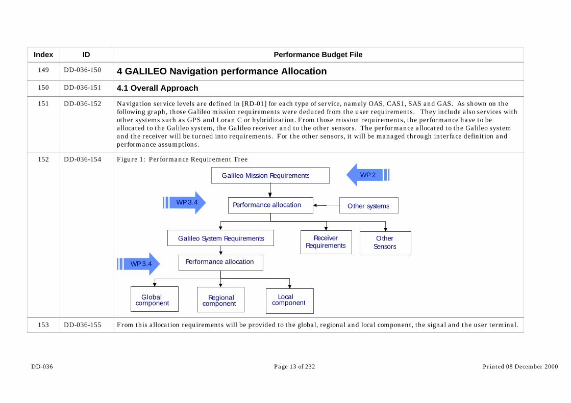
Navigation service levels are defined in [RD-01] for each type of service, namely OAS, CAS1, SAS and GAS. As shown on thefollowing graph, those Galileo mission requirements were deduced from the user requirements. They include also services withother systems such as GPS and Loran C or hybridization. From those mission requirements, the performance have to beallocated to the Galileo system, the Galileo receiver and to the other sensors. The performance allocated to the Galileo systemand the receiver will be turned into requirements. For the other sensors, it will be managed through interface definition andperformance assumptions.
Figure 1: Performance Requirement Tree
Other systems
Galileo Mission Requirements WP 2
Performance allocation
Globalcomponent
WP 3.4
Galileo System Requirements
WP 3.4
ReceiverRequirements
Performance allocation
Regionalcomponent
Localcomponent
OtherSensors
From this allocation requirements will be provided to the global, regional and local component, the signal and the user terminal.

DD-036 Page 14 of 232 Printed 08 December 2000
Index
154
155
156
ID
DD-036-187
DD-036-188
DD-036-189…
Performance Budget File
Table 4: Performance Requirement Trace-ability within GALA deliverables
Global Regional Local User Terminal SignalGlobal Services
a a aGlobal + Regional
Services a a a aGlobal + local
Services a a a
DD31 DD32 DD33 MOPS SIS-ICD
4.2 Galileo Mission Requirements
The Galileo Mission Requirements extracted from [RD-01] are detailed above:

DD-036 Page 15 of 232 Printed 08 December 2000
Index ID
…DD-036-189
Performance Budget File
Accuracy Integrity
Position(NSE 95%)
Serv
ice
Leve
l
Oth
er S
yste
m
Num
ber o
fFr
eque
ncie
s
Cove
rage
(lat
)
Mas
king
Ang
le(°
)
Hor. Vert.
Velo
city
Tim
ing
Cont
inui
ty ri
sk
Risk
TTA
Hor.
Alar
mLi
mit
Vert.
Ala
rmLi
mit
Avai
labi
lity
OAS-G1 No 1 90S/90N 10 16m 36m(30m up to 75°)
50cm/s 0.1s NA NA NA NA 99%
OAS-G2 No 2 90S/90N 10 7m 15m(12m up to 75°)
20cm/s 0.1s NA NA NA NA 99%
OAS-GS GPS 2+2 90S/90N 10 4m 10m(8m up to 75°)
20cm/s 0.1s NA NA NA NA 99%
CAS1-G No 2 90S/90N 10 7m 15m(12m up to 75°)
20cm/s
10 to 20 ns static100ns dynamic
2.10-4/ hour5s outage 2.10-7/ hour 10s 20m 45m
(35m up to 75°) 99%
CAS1-GS GPS 2+2 90S/90N 10 4m 10m(8m up to 75°) NA
10 to 20 ns static100ns dynamic
2.10-4/ hour5s outage 2.10-7/ hour 10s 13m 32m
(25m up to 75°) 99%
CAS1-L1 No 2 local in90S/90N 10 0.8m 1.2m
(1m up to 75°) NA10 to 20 ns static100ns dynamic
2.10-4/ hour1s outage 2.10-7/ hour 1s 2m 3.5m 99%
CAS1-L2 No 2 local in90S/90N 10 0.8m 1.2m
(1m up to 75°) NA10 to 20 ns static100ns dynamic
2.10-4/ hour5s outage 2.10-7/ hour 10s
tbc 2m 3.5m 99%
CAS1-L3 No 3 local in90S/90N 10 tbd tbd tbd Tbd tbd tbd tbd tbd tbd tbd
SAS-Gen route No 2 90S/90N 10 100
m NA 20cm/s
10 to 20 ns static100ns dynamic
2.10-4/ hour10s outage 2.10-7/ hour 15s 556m NA 99%
SAS-GNPA No 2 90S/90N 10 100
m NA 20cm/s
10 to 20 ns static100ns dynamic
2.10-5/ hour5s outage 2.10-7/ hour 10s 556m NA 99.9%
SAS-GCAT1 No 2 90S/90N 10 6m 6m 20cm/
s10 to 20 ns static100ns dynamic
10-5/ 15s1s outage
3.510-7/150s 6s 11m 15m 99%
SAS-GSCAT1 GPS 2+2 90S/90N 10 3m 4m 20cm/
s10 to 20 ns static100ns dynamic
10-5/ 15s1s outage
3.510-7/150s 6s 8m 10m 99.9%
SAS-RCAT1 No 2 local in
90S/90N 10 6m 6m 20cm/s
10 to 20 ns static100ns dynamic
10-5/ 15s1s outage
3.510-7/150s 6s 11m 15m 99%
SAS-RMGPS
+ GNSS12+2 Regional –
GNSS1 10 3m 4m 20cm/s
10 to 20 ns static100ns dynamic
10-5/ 15s1s outage
3.510-7/150s 6s 8m 10m 99.9%
SAS-L No 2 local in90S/90N 10 1m 1.5m 20cm/
s10 to 20 ns static100ns dynamic
5*10-6/ 15s1s outage
2*10-9/150s 1s 3m 5.5m 99.9%
GAS-G No 2 90S/90N 10 6m 6m 20cm/s
10 to 20 ns static100ns dynamic
10-5/ 15s1s outage
3.510-7/150s 6s 11m 15m 99%
GAS-GS GPS 2+2 90S/90N 10 3m 4m 20cm/s
10 to 20 ns static100ns dynamic
10-5/ 15s1s outage
3.510-7/150s 6s 8m 10m 99.9%
GAS-L No 2 local in90S/90N 10 1m 1.5m 20cm/
s10 to 20 ns static100ns dynamic
5*10-6/ 15s1s outage
2*10-9/150s 1s 3m 5.5m 99.9%
EGNOS-2GPS
+GNSS11 Regional
GNSS1 5° 100m - - 20 ns 2.10-5/ hour 2*10-7/ hour 10s 556m - 99.9%
EGNOS-3AGPS
+GNSS11 Europe 5° 7.7m 7.7m - 20 ns 10-6/ 150s 3.5*10-7/
150s 6s 20m 20m 95%
EGNOS-3BGPS
+GLO+GNSS1
1 Europe 5° 4m 4m - 20ns 10-6/ 150s 3.5*10-7/150s 6s 10m 10m 95%
EGNOS-3CGPS
+GNSS12 Regional
GNSS1 5° 7.7m 7.7m - 20ns 10-6/ 150s 3.5*10-7/150s 6s 20m 20m 99%

DD-036 Page 16 of 232 Printed 08 December 2000
Index
157
158
159
160
161
162
163
164
ID
DD-036-201
DD-036-202
DD-036-203
DD-036-204
DD-036-205
DD-036-206
DD-036-207
DD-036-208
Performance Budget File
4.3 Architecture Identification
The goal of this chapter is to allocate the top-system requirements to the different functions of the system. The differentfunctions necessary to provide the different services are:
- The global navigation function
- The global integrity function
- The regional integrity function
- The local functions
- The receiver
The allocation of performance is made according to the system components used to provide the service. Among all the servicessome of them are provided with the same combination of components. Therefore for those services the way to perform allocationbetween components will be similar even thought the final allocate requirements might be different. From allocation point ofview, it is wise to differentiate four cases for Galileo only services:
Global Navigation Function
OAS-G1 [Accuracy only]
OAS-G2 [Accuracy only]
OAS-GS (+GPS) [Accuracy only]
SAS-G/En Route [Accuracy, Integrity and Continuity]
Global Navigation function and Global Integrity function
CAS1-G [Accuracy, Integrity and Continuity]
CAS1-GS (+GPS) [Accuracy, Integrity and Continuity]
SAS-G/NPA [Accuracy, Integrity and Continuity]
SAS-G/Cat1 [Accuracy, Integrity and Continuity]
SAS-GS [Accuracy, Integrity and Continuity]
GAS-G [Accuracy, Integrity and Continuity]

DD-036 Page 17 of 232 Printed 08 December 2000
Index
188
189
190
191
192
193
194
ID
DD-036-234
DD-036-235
DD-036-236
DD-036-237
DD-036-239
DD-036-240
DD-036-241
Performance Budget File
GAS-GS (+GPS) [Accuracy, Integrity and Continuity]
Global Navigation Function and Regional Integrity function
SAS-R [Accuracy, Integrity and Continuity]
SAS-RM (+GPS) [Accuracy, Integrity and Continuity]
EGNOS 2 [Accuracy, Integrity and Continuity]
EGNOS 3A [Accuracy, Integrity and Continuity]
EGNOS 3B [Accuracy, Integrity and Continuity]
EGNOS 3C [Accuracy, Integrity and Continuity]
Global Navigation function and Local functions
CAS1-L1/2/3 [Accuracy, Integrity and Continuity]
SAS-L [Accuracy, Integrity and Continuity]
4.4 Allocation with other sytems
The other system that are candidates to be integrated with Galileo are GPS and Loran C (and UMTS). Those systems arealready in place and cannot be significantly modified in terms of performance to fulfill all the Galileo needs.
- For GPS, the system has been working for 20 years already. Its current performances are well known and some informationon the expected performance in 2010 are available.
- For Loran C, the system is also already working. Although Europe can improve Loran C zone of coverage if it appears that itprovides a real added value to Galileo, it will be difficult to improve the accuracy performance of Loran C.
Therefore the services defined with Galileo and other systems will have two different situations according to external systemsconsidered.
For systems such as Loran C or UMTS final performances will depend on expected performance of those systems andperformances expected from Galileo only. This means that, when the two systems are added “independently”:
- No specific requirements on the other systems should come from the services defined with Galileo and other systems. Theperformance estimation will be based on minimum performances expected from those other systems and the services will beprovided with the right level of quality only if the other systems are consistent with the assumptions made.

DD-036 Page 18 of 232 Printed 08 December 2000
Index
195
196
197
198
199
200
201
202
ID
DD-036-242
DD-036-243
DD-036-244
DD-036-245
DD-036-246
DD-036-247
DD-036-248
DD-036-249
Performance Budget File
- No specific requirements on the Galileo system should come from the services defined with Galileo and other systems
For GPS, the situation is different. GPS and Galileo are not independent anymore since the Galileo system is required toprovide GPS integrity. Therefore the performance for the provision of this integrity service have to be specified. In that sensethe Galileo + GPS that requires GPS integrity will imply requirements on the system and demands as well an allocation. Forthose services the GPS assumptions that shall be taken into account for Galileo system design shall be clearly stated.
4.5 Accuracy
Accuracy allocation between the receiver and the SIS is made through the computation of the UERE (User Equivalent RangeError). A budget is allocated for the error that are receiver specific such as thermal noise, interference and multipath. Thoseerror budget are added to the ones that are more SIS specific such as clock and ephemeris error, ionospheric error ortropospheric error. The UERE computation is detailed in the following part of the document (Chapter 4).
4.6 Global Navigation Function Only services
4.6.1 Performance Allocation for OAS-G1 & 2
The OAS-G (1&2) services do not include any guaranty of service on integrity or continuity performance. Therefore, theallocation between elements has only to be done for the availability of accuracy of the service. The availability of accuracy is thepercentage of time for which the accuracy required is achieved. The following trees shows a preliminary allocation between thedifferent elements of the global component. Indeed for such a service, since it is only provided by the global component, does notimply any specific requirements in terms of performance on the Regional or Local components. The availability are even onlyallocated to the SIS. The target for OAS is mass market, it means people that want to buy cheap receiver. Furthermore,although specifying a SIS availability makes sense, for the receiver parameter such as MTBF and especially MTTR are left toreceiver manufacturer and service provider.
Within the SIS, the availability is split between the ranging function and the communication function. A first apportionment isto put the lack of availability due to navigation message out of date negligible comparing to the lack of availability due satellitegeometry which is much more demanding. However these are only preliminary results. This is not the task of GALA to allocatethe performance between the elements of a same component. Concerning the constellation availability, it appears not possibleto go deeper in the allocation with this kind of approach. Indeed, the geometry availability will be the average of the availabilityobtained with different failure scenarios weighted by the probability of occurrence of those scenarios. Therefore only a Globalnumber can be specified. The impact of one failure has to be traded off with the constellation design and the robustness ofGalileo satellites.

DD-036 Page 19 of 232 Printed 08 December 2000
Index
203
204
205
206
207
ID
DD-036-250
DD-036-251
DD-036-253
DD-036-254
DD-036-255
Performance Budget File
RQ-Gl The global navigation function shall be able to support an OAS-G1 service with an availability of 99%.
RQ-Gl The global navigation function shall be able to support an OAS-G2 service with an availability of 99%.
Figure 2: Availability Allocation Tree for OAS-G1/2Availability of Accuracy
0.99
RxNot included in Perf budget
SIS0.99
Nav messageout of date
0.999
OSS
OSPF
GWAN
ULS
GeometryHNSE<Accuracy limit
0.99
SatelliteFault-free
1 failure 2 failures 3 failures
Fault freeAvailability
1 failurestate probability
2 failuresAvailability
3 failureAvailability
1 failureavailability
2 failuresstate probability
Fault freestate probability
3 failuresstate probability
Global
Global
4.6.2 Integrity Performance Allocation for SAS-G/En Route
For some of the services no GIC is available to fulfill the integrity requirements. For OAS services the consequences are notimportant since no integrity requirements are officially specified for integrity. However, for a SAS-G to be used for safetycritical application in a global basis, RAIM has to be used to insure the system integrity.
DD-036 Page 20 of 232 Printed 08 December 2000
Index
208
209
210
211
212
213
214
215
216
217
ID
DD-036-256
DD-036-257
DD-036-258
DD-036-259
DD-036-260
DD-036-261
DD-036-262
DD-036-263
DD-036-265
DD-036-266
Performance Budget File
The budget is first split between the SIS and the receiver. Within the SIS two situations occur. The nominal case where thereare no error on the pseudo-range. This one is the most probable and its probability of occurrence is close to 1. The secondsituation is when a single failure arises on one measurement without warning from the SIS. When no GIC is present theprobability of occurrence of this event is not negligible and has to be taken into account. On the contrary when GIC is present,the space segment is closely monitored by a ground segment that will generate flags as soon as a failure occurs on one satellite.Therefore the probability of undetected failure remains low. Without GIC, failure shall be detected by the RAIM.
The final integrity risk will then depend from :
- the Probability of occurrence of a failure
- the Miss detection probability of the RAIM
In order to get a clear idea of the final user integrity risk, a thorough identification of the failure mode has to be done. Once thisinformation is available, it will be possible to tune the performance of integrity risk mitigation techniques and conclude on thefinal system performance in terms of integrity and availability. Since, until now neither the failure mode nor their probabilityof occurrence are clearly identified, assumptions relying on what has been observed with the other radio navigation systemshave been taken.
First, two integrity macro failure mode are selected:
- Misleading information due to satellite failure
- Misleading information due to local effects
For the first failure mode, no specific data is available for Galileo. This is not surprising since this kind of parameter is usuallyassessed with measurement campaigns and detailed RAMS analysis. Nevertheless some information are available for GPS. According to the WAAS-MOPS [RD-014], the hazardous failure rate for one GPS satellite among 24 is 10-4/h. The same valuewill be used for Galileo.
For local effects, information dealing with occurrence probability are not available even for GPS. Therefore the conservativestrategy selected is the following. Since no information is available in local effects and in order not to neglect one failure modecomparing to the other, the value selected for satellite failure mode is selected for local effects as well.

DD-036 Page 21 of 232 Printed 08 December 2000
Index
218
219
220
221
222
223
224
225
ID
DD-036-267
DD-036-268
DD-036-269
DD-036-270
DD-036-271
DD-036-272
DD-036-273
DD-036-274
Performance Budget File
Once the integrity risk due to one failure is specified using a top-down approach from the user needs and that the failure modesare identified, the RAIM can be tuned to meet the requirements. For SAS-G service the RAIM miss detection is specified at 2.5
10-4.
The third cases mentioned in the allocation tree is the probability that the user is confronted to a multiple failure configuration. It means that several range measurement are corrupted. Multiple failure can arise from the combination of two independent
single failures. In that case, if the probability of having one failure is assumed equal to 10-4/h the probability to have two is
equal to 10-8/h. This probability is of the same order of magnitude of the risk budget for fault free and single failure cases.
However, although the RAIM is designed for single failure cases, its detection performances is not null for multiple failure
cases. Assuming a RAIM miss detection probability of 10-2 is enough for the risk due to multiple failure being negligible.
However, another source of multiple failure is the common mode of failure (i.e: one event may cause a failure on severalsatellites). Typically, an error in the ephemeris determination will have an impact on several satellites. Therefore theprobability of event of common failure mode has to be specified. In order not to impact the total integrity risk, the specification
for multiple SIS HMI has been selected equal 10-8/h which is equal to the same order of magnitude of the multiple failuresevents caused by independent single failures combination
Depending of the user situation the integrity risk can be allocated differently on the horizontal and vertical component. In thecase that both components matter, the risk will be allocated part on the vertical and part on the horizontal component. Forusers such as civil aviation, one dimension is always favored (horizontal for En Route, vertical for Cat 1) and all the risk isallocated to it. For SAS-G/En route, no requirement is identified in horizontal, therefore all the risk is allocated to the verticalperformance.
RQ-Gl The probability that the global navigation function sends a hazardous misleading information to theSAS-G/En Route user though the SIS affecting a single satellite shall be less than 1E-4/h.
RQ-Gl The probability that the global navigation function sends a hazardous misleading information to theSAS-G/En Route user though the SIS affecting a several satellites shall be less than 1E-8/h.
RQ-Rx The integrity risk due to the SAS-G/En Route user segment shall be less than 1E-7/h. User integrity risk covers theprobability of the user segment to generate on its own a misleading information due to hardware or software. Integrity riskdue to RAIM algorithm performance is not included in the integrity risk user segment budget.
DD-036 Page 22 of 232 Printed 08 December 2000
Index
226
227
228
ID
DD-036-275
DD-036-276
DD-036-277
Performance Budget File
The TTA specified for the SAS-G/En Route service is equal to 15 seconds. However the service tolerate a 10 seconds outagewithout service interruption. Therefore 5 seconds remain left for integrity determination using RAIM. The RAIM specified inthe MOPS/RTCA ([RD-014]) and that has been selected in GALA as well is a snapshot algorithm. Therefore the performanceare defined assuming only one measurement. Therefore removing the contribution of the receiver the TTA allocated to theglobal navigation function cannot be less than 1 second. Therefore the TTA allocation between the global navigation functionand the receiver is as follows:
RQ-Sg The signal structure shall allows to provide a pseudo-range measurement at least every second.
RQ-Rx In case of a failure detectable by RAIM, the period between the instant when a faulty pseudo-range is used in thenavigation solution and the instant that an alarm is displayed to the user shall not exceed 4 seconds.

DD-036 Page 23 of 232 Printed 08 December 2000
Index
229
230
231
ID
DD-036-279
DD-036-280
DD-036-281
Performance Budget File
Figure 3: Integrity Allocation Tree for SAS-G/En Route service
Rx Integrity Risk
User Integrity Risk2E-7/h
Fault-free Integrity Risk
5E-8/h
XNSE>XPLin nominal case
5E-8/h
Fault-Free stateProbability
≈ 1
1E-7/h
Single failure Integrity Risk
5E-8/h
XNSE>XPLwith one failure
≈ 1
Undetected single failure probability
5E-8/h
Multiple failure Integrity Risk
Negligible
Single SIS failure2E-4/h
RAIM miss detection
2.5E-4
Single SIS due to localeffect1E-4/h
Single SIS due tosatellite failure
1E-4/h
Probability UnknownGPS figure extracted
from MOPS
or
or
and and
and
GLOBAL
Independent failure mode
1E-8/h(estimation)
Common failure mode
1E-8/h
HMI on data message
RAIM≈1E-2
Multiple failureProbability
2E-8/h
and
GLOBAL
4.6.3 Continuity Performance Allocation for SAS-G/En Route
The continuity risk is allocated between the receiver, the geometric performance of the constellation and the RAIM false alarm. The budget on the RAIM false alarm is 10-5/h for SAS-G/En Route service which is similar to the MOPS requirements for EnRoute phase of flight. The number of independent samples in one hour is assumed equal to 10. Therefore the RAIM false alarm
probability is selected at 10-6 per independent samples. As for the miss detection this budget has to be split into two budgets,one for horizontal and one for vertical dimension.

DD-036 Page 24 of 232 Printed 08 December 2000
Index
232
233
234
235
236
237
ID
DD-036-282
DD-036-283
DD-036-285
DD-036-286
DD-036-287
DD-036-288
Performance Budget File
RQ-Gl The probability to loose the SAS-G/En Route service because of a failure on the Global navigation function shall be lessthan 5E-5/h. (The interruption due to RAIM false alarm are not covered by this budget).
RQ-Rx The probability of failure of the SAS-G/En Route user segment shall be less than 2E-4/h
Figure 4: Continuity Allocation in Global for SAS-G/En Route
SIS1E-4/h
XPL>XAL9E-5/h
Loss of Continuitydue to Satellite
Failure5E-5/h
Loss of Continuitydue to Local Effects
(Interference/Masking)4E-5/h
RAIMfalse alarm
1E-5/h
Receiver1E-4/h
Continuity Risk2E-4/h
or
or
or
Global
4.6.4 Availability Performance Allocation for SAS-G/En Route
For the same reasons mentioned above for OAS service the receiver is not included in the availability performance budget. Theavailability required is in fact the SIS availability. It is again split between the navigation function and the communicationfunction. The criteria to declare the system available is that the protection level computed with RAIM is to be less than thealarm limit.
RQ-Gl The unavailability of the SIS SAS-G/En Route service due to the global navigation function shall be less than 1E-2. The availability includes availability of:

DD-036 Page 25 of 232 Printed 08 December 2000
Index
238
239
240
241
242
243
244
245
246
247
248
249
250
251
252
253
254
ID
DD-036-289
DD-036-290
DD-036-291
DD-036-292
DD-036-293
DD-036-294
DD-036-295
DD-036-296
DD-036-297
DD-036-298
DD-036-299
DD-036-300
DD-036-301
DD-036-302
DD-036-303
DD-036-304
DD-036-305
Performance Budget File
- Accuracy at 95%, 100m horizontal
- Integrity provided by RAIM in for a HPL of 556m with 2.5E-4 miss detection probability and 1E-6 false alarm probability
- Continuity with a continuity risk less than 5E-5/h
4.7 Global Navigation Function + Global Integrity Function
4.7.1 Integrity Performance Allocation for CAS1-G
4.7.1.1 GIC and RAIM allocation
The CAS1 users have at their disposal at system level two barriers that they can use to set their final integrity risk: the GIC(Galileo Integrity Channel) and the RAIM (Receiver Autonomous Integrity Monitoring). Those two techniques have differentfeatures:
- GIC
- Able to detect and isolate multiple satellites failure
- Less demanding in terms of availability
- Unable to detect local effects
- RAIM
- Able to detect local effects
- Able to detect single satellite failure.
- Detection capacity very demanding in terms of availability
- Failure isolation possible but much too demanding in terms of availability
- Performance against multiple failure not very well characterized
DD-036 Page 26 of 232 Printed 08 December 2000
Index
255
256
257
258
259
260
261
262
ID
DD-036-306
DD-036-307
DD-036-308
DD-036-310
DD-036-311
DD-036-315
DD-036-316
DD-036-317
Performance Budget File
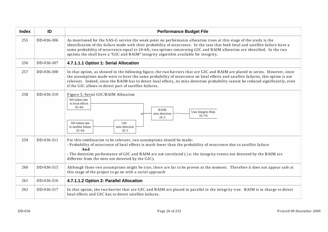
As mentioned for the SAS-G service the weak point on performance allocation trees at this stage of the study is theidentification of the failure mode with their probability of occurrence. In the case that both local and satellite failure have asame probability of occurrence equal to 10-4/h, two options concerning GIC and RAIM allocation are identified. In the twooptions the shall have a “GIC and RAIM” integrity algorithm available for integrity.
4.7.1.1.1 Option 1: Serial Allocation
In that option, as showed in the following figure, the two barriers that are GIC and RAIM are placed in series. However, sincethe assumptions made were to have the same probability of occurrence on local effects and satellite failures, this option is notrelevant. Indeed, since the RAIM has to detect local effects, its miss detection probability cannot be reduced significantly, evenif the GIC allows to detect part of satellite failures.
Figure 5: Serial GIC/RAIM AllocationSIS failure due to local effects
1E-4/h
SIS failure dueto satellite failure
1E-4/h
GIC miss detection
1E-3
RAIMmiss detection
1E-3
User Integrity Risk1E-7/h
or
For this combination to be relevant, two assumptions should be made:- Probability of occurrence of local effects is much lower than the probability of occurrence due to satellite failure
And- The detection performance of GIC and RAIM are not correlated ( i.e: the integrity events not detected by the RAIM aredifferent from the ones not detected by the GIC).
Although those two assumptions might be true, there are far to be proven at the moment. Therefore it does not appear safe atthis stage of the project to go on with a serial approach
4.7.1.1.2 Option 2: Parallel Allocation
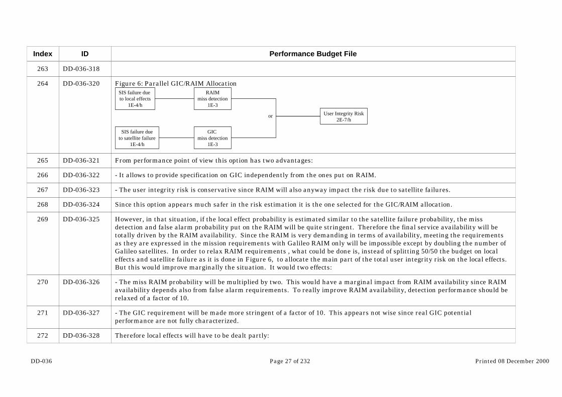
In that option, the two barrier that are GIC and RAIM are placed in parallel in the integrity tree. RAIM is in charge to detectlocal effects and GIC has to detect satellite failures.
DD-036 Page 27 of 232 Printed 08 December 2000
Index
263
264
265
266
267
268
269
270
271
272
ID
DD-036-318
DD-036-320
DD-036-321
DD-036-322
DD-036-323
DD-036-324
DD-036-325
DD-036-326
DD-036-327
DD-036-328
Performance Budget File
Figure 6: Parallel GIC/RAIM AllocationSIS failure due to local effects
1E-4/h
SIS failure dueto satellite failure
1E-4/h
GIC miss detection
1E-3
RAIMmiss detection
1E-3
User Integrity Risk2E-7/h
or
From performance point of view this option has two advantages:
- It allows to provide specification on GIC independently from the ones put on RAIM.
- The user integrity risk is conservative since RAIM will also anyway impact the risk due to satellite failures.
Since this option appears much safer in the risk estimation it is the one selected for the GIC/RAIM allocation.
However, in that situation, if the local effect probability is estimated similar to the satellite failure probability, the missdetection and false alarm probability put on the RAIM will be quite stringent. Therefore the final service availability will betotally driven by the RAIM availability. Since the RAIM is very demanding in terms of availability, meeting the requirementsas they are expressed in the mission requirements with Galileo RAIM only will be impossible except by doubling the number ofGalileo satellites. In order to relax RAIM requirements , what could be done is, instead of splitting 50/50 the budget on localeffects and satellite failure as it is done in Figure 6, to allocate the main part of the total user integrity risk on the local effects. But this would improve marginally the situation. It would two effects:
- The miss RAIM probability will be multiplied by two. This would have a marginal impact from RAIM availability since RAIMavailability depends also from false alarm requirements. To really improve RAIM availability, detection performance should berelaxed of a factor of 10.
- The GIC requirement will be made more stringent of a factor of 10. This appears not wise since real GIC potentialperformance are not fully characterized.
Therefore local effects will have to be dealt partly:

DD-036 Page 28 of 232 Printed 08 December 2000
Index
273
274
275
276
277
278
279
280
281
ID
DD-036-329
DD-036-330
DD-036-331
DD-036-332
DD-036-333
DD-036-334
DD-036-335
DD-036-336
DD-036-337
Performance Budget File
- With receiver detection techniques for multipath and interference. This will have as impact to decrease the probability ofoccurrence of local effects at RAIM input
- And with RAIM but augmented with other system (GPS, GLONASS…) or other sensors (INS, baro-altimeter or clocks).
Therefore the specifications put on RAIM on the following sections will be assumed to be fulfilled by combining the twotechniques mentioned above.
Furthermore since RAIM/AAIM performance will most likely depend much more from the type of hybridization used than theconstellation performance itself, no RAIM specifications will be put on the global component. The strategy will be to assesswhat is available in terms of RAIM performance from the constellation and to see what is missing in terms of on boardaugmentation to fulfill the requirements for local effect detection. For trace-ability of the requirements, the RAIM specificationwill nevertheless remain as NCDP (Non Critical Design Parameter) on the global component.
4.7.1.1.3 User Integrity Risk Allocation tree
The risk at user level is first allocated between the SIS and the receiver. Risk on the receiver does not include RAIM. RAIM isan algorithm specified at system level. Therefore, although it is implemented in the receiver, its performance depends on theSIS. Receiver integrity risk includes all the HMI (hazardous misleading information) generated by a malfunction of thehardware or software. Nevertheless, although such requirements might be achievable with enough redundancy it will make thereceiver very expensive. Although it might not be a problem for SAS users, it will certainly be for CAS1 users. Nevertheless,according to user need in integrity requirements, the receiver specification can be relaxed. The important point from the SISside is to make sure that the user is provided with a SIS that can allow him to reach a 10-7/h integrity risk.
On the SIS the risk is split into three categories:
- Fault-Free: This is the user risk when the system is working nominally. This risk is not zero since normal distribution areassumed to model the errors. Therefore there is always a risk to be out of the protection level without having any failure on thesystem.
- Risk due to a single SIS failure: This is the user risk when a failure arise on one SIS. The probability that a failure on the SISwill lead to a position error exceeding the specified alarm limit is estimated to 1. Therefore the risk in this situation will bemainly driven by the probability of having a undetected (by GIC or RAIM) single failure at user level.

DD-036 Page 29 of 232 Printed 08 December 2000
Index
282
283
284
285
ID
DD-036-338
DD-036-340
DD-036-341
DD-036-342
Performance Budget File
- Risk due to multiple SIS failure The situation is the same as for single failure integrity risk. Furthermore, since theprobability of having multiple failure is already low, the probability of having undetected multiple failures appears negligiblecomparing to other source of integrity risk.
Figure 7: Integrity performance allocation at system level for CAS1-G serviceUser Integrity Risk
2E-7/h
Fault-free Integrity Risk
5E-8/h
XNSE>XPLin nominal case
5E-8/h
Fault-Free stateProbability
≈ 1
Rx Integrity Risk1E-7/h
Single failure Integrity Risk
5E-8/h
XNSE>XPLwith one failure
≈ 1
Undetected single failure probability
5E-8/h
Multiple failure Integrity Risk
Negligible
XNSE>XPLwith multiple
Failure
Undetected multiplefailure probability
1E-10/h
RAIM miss detection
2.5E-4
Single SIS due to localeffect
1E-4/h
Undetected Globalsingle SIS by GIC
2.5E-8/h
Global Single SIS
1E-4/h
GIC single failure miss detection
2.5 E-4
Multiple SISdue to local
Effect1E-8/h
Multiple SIS failureincluding an undetected
satellite failurenegligible
Global multiple SIS
GIC multiple failure miss detection
Undetected Localsingle SIS by RAIM
2.5E-8/h
and and
and and
and
or
or
or
and
GIC/RAIM
RAIMmiss detection
1E-2
≈ 1
and
This tree allows to deduct the performance that shall be assessed from the global component designer in order to fulfill theglobal user integrity risk requirement. In the next part, this performance will be allocated on the different functions of theglobal component.
RQ-Rx The integrity risk due to the CAS1-G user segment shall be less than 1E-7/h. User integrity risk covers the probabilityof the user segment to generate on its own a misleading information. Integrity risk due to RAIM algorithm performance is notincluded in the integrity risk user segment budget.

DD-036 Page 30 of 232 Printed 08 December 2000
Index
286
287
288
289
290
291
292
293
ID
DD-036-343
DD-036-344
DD-036-345
DD-036-346
DD-036-347
DD-036-348
DD-036-349
DD-036-351…
Performance Budget File
4.7.1.2 Integrity Risk Allocation within Global component
The risk due to a single failure, as explained before for the RAIM, depends on two parameters:
- The probability to have a failure
- The probability of miss detection of this failure
The first parameters depends from the satellites and control segment but also from the orbito & synchro component of themission segment. Indeed this failure mode includes also the eventuality of the broadcast of a corrupted SISA to the users.
The second parts concerns the ability of the ground segment monitoring to detect an event and broadcast a alarm to the userwithin the TTA required. This function is split between the detection function and transmission function. The detectioncomponent includes the monitoring station and the integrity processing facility algorithms. The transmission componentsincludes the chain from the integrity processing facility to the user.
It has to be pointed out that the elements mentioned in this figure are the ones currently identified in GALA architecture. However, the requirements expressed in this document are relatively independent from the architecture considered. Therequirements are put on functions and not on elements.
Figure 8: Integrity Risk Allocation between elements of the Global component

DD-036 Page 31 of 232 Printed 08 December 2000
Index
294
295
ID
…DD-036-351
DD-036-352
DD-036-353
Performance Budget File
Undetected Globalsingle SIS by GIC
2.5E-8/h
Global Single SIS
1E-4/h
GIC single failure miss detection
1.5E-4
Invalid SISA At SV output
1E-5/h
Corruption of valid SISA in SIS
1E-8/h
Satellite not monitored not flaggedNegligible
Miss transmissionof Alert within TTA
1.5E-4
SatelliteFailure1E-4/h
Miss Detectionwithin T1*
1E-4
Transmission failurewithin T2*
5E-5
Transmissionfrom IPF to GUI
2E-5
Transmission fromGUI to Satellite
2E-5
Integrity message loss due to biterror rate
1E-5Transmission delay
Data corruption
Transmission delay
Data corruption
*T1=Allocated budget for detectionT2=Allocated budget for transmissionTTA=T1+T2
GLOBALand
oror
or
or
or or
or
From this tree, it is possible to identify requirements for the navigation message robustness:
- Among the 10s TTA, 1 second is assumed allocated to the message. The structure of the message is also assumed synchronouswith frames of 1 second. Therefore if the alarm message is lost or not decoded correctly the TTA cannot be met. The probabilitytolerated for this kind of event is 10-5. Therefore the probability to loose an integrity message shall be less than 10-5. The lossof a message can come either of incoherence detected but not corrected in the message by the CRC or from an error in themessage not detected by the CRC. At first sight the probability of the second event appears very remote comparing to the firstone.

DD-036 Page 32 of 232 Printed 08 December 2000
Index
296
297
298
299
300
301
ID
DD-036-354
DD-036-355
DD-036-356
DD-036-357
DD-036-358
DD-036-359
Performance Budget File
- The integrity flags provide information on the correctness of the SISA. SISA provides information on the correctness on orbitosynchro parameters. In order to ensure integrity it is very important for those parameters to be coherent with one another. Therefore the probability to have an HMI generated by the message on SISA and orbito synchro parameters has to be veryremote. The integrity risk allocated to this event is estimated at 10-8/h
It is also important to keep in mind that signal design is not a task that is in the scope of the global component designer. Therefore, since the bit error rate impacts the integrity risk as described above, the integrity risk requirements of 1.5E-8/h thathas to be fulfilled by the global components assuming a loss of message due to bit error rate of 1E-5. This figure is a necessaryinput for the Global component design has to be provided by GALA. This is done through the Signal In Space ICD. That is puton the global component designer to be used as inputs. For specification purpose, it may be wise to allocate performance to theglobal component assuming a “fault-free” SIS. In that case the specification would be as follow:
RQ-Gl The probability that the global navigation function sends an hazardous misleading information to the CAS1-G userwithout that the global integrity function sends a warning within the TTA allocated shall be less than 1.5E-8/h.
4.7.1.3 Time To Alarm Allocation
The following graph shows an apportionment between the system and the receiver for the time to alarm:

DD-036 Page 33 of 232 Printed 08 December 2000
Index
302
303
304
305
306
307
ID
DD-036-361
DD-036-362
DD-036-363
DD-036-364
DD-036-365
DD-036-366
Performance Budget File
Figure 9: Time To Alarm allocation for CAS1-G service
GMS GPF GUI ULS
MEO
User
Integrity Event
0.8s5.2s without message loss (Up to 9.2s with message losses)
Global
Alarm
For CAS1 the TTA requirements coming from user needs is equal to 10 seconds. However since other services demand a 6second TTA, the Galileo infrastructure will have to be able to provide 6 seconds TTA to users. Therefore, the requirementsallocated to the global component will be in line with a 6 seconds time to alarm. The other part of the budget is allocated to thesignal. It means that the alarm will be repeated at least five times and that the user can afford to loose 4 message withoutrisking to miss it or to jeopardize the 10s TTA performance.
RQ-Gl The TTA allocated to global component of the integrity function for CAS1-G service is equal to 5.2 seconds. It includesthe time to detect the misleading information and transmit it to the receiver antenna in nominal conditions (ie without loss ofmessage).
RQ-Rx The time elapsed between the moment when an alarm arrives at the CAS1-G receiver and the alarm is displayed to theuser shall not exceed 0.8s
RQ-Sg When an integrity alarm is sent to the user, it shall be available in the message for 5 seconds. The loss of an integrityalarm message due to bit error rate on CAS1-G service shall not exceed 1E-5
RQ-Sg The probability that the an HMI is generated within the CAS1-G navigation message due to bit error rate shall be lessthan 10-8/h
DD-036 Page 34 of 232 Printed 08 December 2000
Index
308
309
310
311
312
313
314
315
316
ID
DD-036-367
DD-036-368
DD-036-369
DD-036-370
DD-036-371
DD-036-372
DD-036-373
DD-036-374
DD-036-375
Performance Budget File
4.7.2 Integrity Performance Allocation for CAS1-GS
As mentioned above, the parameter that is specified to the global component is the probability of undetected failure. Thisparameter depends of the satellite failure probability and the detection performance of the ground segment. Since, in globalthe space and mission segment are in charge of one entity , it is up to it to allocate the performance on those two functions. However, in the case that Galileo has to provide integrity for GPS, the situation is different. Since GPS constellation is notunder Galileo control, it may be necessary to go one step further in the allocation and starting from an estimation of the GPSfailure rate probability, derive a requirement for failure detection performance.
Providing GPS integrity may have a major impact on the ground segment dimensioning:
- First, if the number of satellite is doubled, the failure rate is doubled as well, and then to keep the same integrity risk got withGalileo only, the ground segment should have performance assessment that are better. This is mainly due to the fact that thetarget in terms of alarm limit for the services including GPS are smaller than the one considered for service provided by Galileoonly.
- Next, in order to detect failure on the system, ground monitoring may not be the only answer. Many checks can beimplemented on board, and then the risk could be allocated between on-board test on-ground test. With GPS satellite, thisapproach is no longer possible to consider. Therefore all the detection performance have to be put on the ground segment.
For the time being, The same logic that has been used to deduct CAS1-G requirements will be used for CAS1-GS requirements. Bit this kind of requirements will have to be completed by the assumptions that shall take into account the designer on the GPSconstellation. Those information are indispensable since the Galileo designer does not control GPS performance.
For this service and all the ones that will be provided by with GPS, the navigation function is supported by Galileo and GPSspace segment.
RQ-Rx The integrity risk due to the CAS1-GS user segment shall be less than 1E-7/h. User integrity risk covers the probabilityof the user segment to generate on its own a misleading information. Integrity risk due to RAIM algorithm performance is notincluded in the integrity risk user segment budget.
RQ-Gl The probability that the global navigation function sends an hazardous misleading information to the CAS1-GS userwithout that the global integrity function sends a warning within the TTA allocated shall be less than 1.5E-8/h.

DD-036 Page 35 of 232 Printed 08 December 2000
Index
317
318
319
320
321
322
323
324
325
326
327
ID
DD-036-376
DD-036-377
DD-036-378
DD-036-379
DD-036-380
DD-036-381
DD-036-382
DD-036-383
DD-036-384
DD-036-385
DD-036-386
Performance Budget File
RQ-Gl The TTA allocated to global component of the integrity function for CAS1-GS service is equal to 5.2 seconds. It includesthe time to detect the misleading information and transmit it to the receiver antenna in nominal conditions (ie without loss ofmessage).
RQ-Rx The time elapsed between the moment when an alarm arrives at the CAS1-GS receiver and the alarm is displayed tothe user shall not exceed 0.8s
RQ-Sg When an integrity alarm is sent to the user, it shall be available in the message for 1 seconds. The loss of an integrityalarm message due to bit error rate on CAS1-GS service shall not exceed 1E-5
RQ-Sg The probability that the an HMI is generated within the CAS1-GS navigation message due to bit error rate shall be lessthan 10-8/h
4.7.3 Integrity Performance Allocation for SAS/NPA
At system level the integrity tree used to allocate the risk between GIC and RAIM for SAS-G/NPA service is quite similar to theone used for CAS1-G. This is due to the fact that the overall architecture used for those two services is similar. The same logichas been used to deduct CAS1-G requirements:
RQ-Rx The integrity risk due to the SAS-G/NPA user segment shall be less than 1E-7/h. User integrity risk covers theprobability of the user segment to generate on its own a misleading information. Integrity risk due to RAIM algorithmperformance is not included in the integrity risk user segment budget.
RQ-Gl The probability that the global navigation function sends an hazardous misleading information to the SAS-G/NPA userwithout that the global integrity function sends a warning within the TTA allocated shall be less than 1.5E-8/h.
RQ-Gl The TTA allocated to global component of the integrity function for SAS-G/NPA service is equal to 5.2 seconds. Itincludes the time to detect the misleading information and transmit it to the receiver antenna in nominal conditions (ie withoutloss of message).
RQ-Rx The time elapsed between the moment when an alarm arrives at the SAS-G/NPA receiver and the alarm is displayed tothe user shall not exceed 0.8s
RQ-Sg When an integrity alarm is sent to the user, it shall be available in the message for 1 seconds. The loss of an integrityalarm message due to bit error rate on SAS-G/NPA service shall not exceed 1E-5

DD-036 Page 36 of 232 Printed 08 December 2000
Index
328
329
330
331
332
333
334
ID
DD-036-387
DD-036-388
DD-036-389
DD-036-390
DD-036-391
DD-036-392
DD-036-394…
Performance Budget File
RQ-Sg The probability that the an HMI is generated within the SAS-G/NPA navigation message due to bit error rate shall beless than 10-8/h
4.7.4 Integrity Performance Allocation for SAS-G/Cat 1
At system level the integrity tree used to allocate the risk between GIC and RAIM for SAS-G/Cat 1 service is quite similar to theone used for CAS1-G. This is due to the fact that the overall architecture used for those two services is similar.
However, one important point is that the two services do not have the same requirements. Therefore, the integrityrequirements allocated on the different components may be different for the two services. For the global component that are thesame ones for the two services, the requirements should as far as possible remain the same. In the case that they weredifferent, only the most stringent would be applicable.
The probability of occurrence of local events or satellite failures has been kept similar to the one used for global services. Thefollowing trees show how the integrity risk is allocated first at system level between GIC and RAIM and next within the Galileoglobal component.
As far as time to alarm is concerned the requirements for SAS-G/Cat1 service is equal to 6 seconds. Therefore the allocation tothe global component is kept equal to 5.2 without loss of message. The allocation to receiver is kept equal to 0.8s. Concerningthe signal, the time allocated is reduced from 5 to 1 second. Therefore the alarm does not need to be repeated several times.
Figure 10: Integrity performance allocation at system level for SAS-G/Cat1 service

DD-036 Page 37 of 232 Printed 08 December 2000
Index
335
336
ID
…DD-036-394
DD-036-395
DD-036-397…
Performance Budget File
User Integrity Risk3.5E-7/150s
Fault-free Integrity Risk1E-7/150s
VNSE>VPLin nominal case
1E-7/150s
Fault-Free stateProbability
≈ 1
Rx Integrity Risk1.5E-7/150s
Single failure Integrity Risk1E-7/150s
XNSE>XPLwith one failure
≈ 1
Undetected single failure probability
1E-7/150s
Multiple failure Integrity Risk
Negligible
XNSE>XPLwith multiple
failure
Undetected multiplefailure probability
RAIM miss detection
1.25E-2
Single SIS due to localeffect
4E-6/150s1E-4/h
Undetected Globalsingle SIS by GIC
5E-8/150s
Global Single SIS
4 10-6/150s1E-4/h
GIC single failure miss detection
1.25E-2
Multiple SISdue to local
effect Undetected Globalmultiple SIS by GIC
Global multiple SIS
GIC multiple failure miss detection
Undetected Localsingle SIS by RAIM
5E-8/150s
and
or
oror
and and
and and
and
RQ-Rx The integrity risk due to the SAS-G/Cat1 user segment shall be less than 1.5E-7/150s. User integrity risk covers theprobability of the user segment to generate on its own a misleading information. Integrity risk due to RAIM algorithmperformance is not included in the integrity risk user segment budget.
Figure 11: Integrity risk allocation within the Galileo global component for SAS-G/Cat1

DD-036 Page 38 of 232 Printed 08 December 2000
Index
337
338
339
ID
…DD-036-397
DD-036-398
DD-036-399
DD-036-400
Performance Budget File
Undetected Globalsingle SIS by GIC
5E-8/150s
Global Single SIS
4E-6/150s
GIC single failure miss detection
7.5E-3
Invalid SISA At SV output4E-8/150s
Satellite not monitored not flaggedNegligible
Miss transmissionof Alert within TTA
7.5E-3
Satellitefailure
4E-6/150s
Miss Detectionwithin T1*
5E-3
Transmission failurewithin T2*2.5E10-3
Transmissionfrom IPF to GUI
1E-3
Transmission fromGUI to User
1E-3
Integrity message loss due to bit error
rate5E-4
Transmission delay
Data corruption
Transmission delay
Data corruption
*T1=Allocated budget for detectionT2=Allocated budget for transmissionTTA=T1+T2
Corruption of validSISA in SIS2E-8/150s
and
or
or
or
oror
Global
As for CAS1-G service, those trees allow to deduct the following requirements on the global component, the receiver and thesignal:
RQ-Gl The probability that the global navigation function sends an hazardous misleading information to the SAS-G/Cat1 userwithout that the global integrity function sends a warning within the TTA allocated shall be less than 3E-8/150s. This figuresassumes a loss of message probability due to bit error rate of 5E-4.
RQ-Gl The TTA allocated to global integrity function for SAS-G/Cat1 service is equal to 5.2 seconds. It includes the time todetect the misleading information and transmit it to the receiver antenna.

DD-036 Page 39 of 232 Printed 08 December 2000
Index
340
341
342
343
344
345
346
347
348
349
350
351
ID
DD-036-401
DD-036-402
DD-036-403
DD-036-404
DD-036-405
DD-036-406
DD-036-407
DD-036-408
DD-036-409
DD-036-410
DD-036-411
DD-036-412
Performance Budget File
RQ-Rx The time elapsed between the moment when an alarm arrives at the SAS-G/Cat1 receiver and the alarm is displayed tothe user shall not exceed 0.8s
RQ-Sg The loss of an integrity alarm message due to bit error rate on SAS-G/Cat1 service shall not exceed 5E-4.
RQ-Sg The probability that a HMI is generated within the SAS-G/Cat1 navigation message due to bit error rate shall be lessthan 2 10-8/150s
4.7.5 Integrity Performance Allocation for SAS-GS/Cat1
RQ-Rx The integrity risk due to the SAS-GS/CAT1 user segment shall be less than 1.5E-7/150s. User integrity risk covers theprobability of the user segment to generate on its own a misleading information. Integrity risk due to RAIM algorithmperformance is not included in the integrity risk user segment budget.
RQ-Gl The probability that the global navigation function sends an hazardous misleading information to the SAS-GS/CAT1user without that the global integrity function sends a warning within the TTA allocated shall be less than 3E-8/150s. Thisfigures assumes a loss of message probability due to bit error rate of 5E-4.
RQ-Gl The TTA allocated to global integrity function for SAS-GS/CAT1 service is equal to 5.2 seconds. It includes the time todetect the misleading information and transmit it to the receiver antenna.
RQ-Rx The time elapsed between the moment when an alarm arrives at the SAS-GS/CAT1 receiver and the alarm is displayedto the user shall not exceed 0.8s
RQ-Sg The loss of an integrity alarm message due to bit error rate on SAS-GS/CAT1 service shall not exceed 5E-4.
RQ-Sg The probability that a HMI is generated within the SAS-GS/CAT1 navigation message due to bit error rate shall be lessthan 2 10-8/150s
4.7.6 Integrity Performance Allocation for GAS-G
The way to allocate integrity risk performance is for GAS-G service is very similar to the one used for SAS-G/Cat1. Since therequirements in terms of integrity risk are exactly the same the allocation trees are also identical. It allows to deduct thefollowing requirements:
DD-036 Page 40 of 232 Printed 08 December 2000
Index
352
353
354
355
356
357
358
359
360
361
362
363
ID
DD-036-413
DD-036-414
DD-036-415
DD-036-416
DD-036-417
DD-036-418
DD-036-419
DD-036-420
DD-036-421
DD-036-422
DD-036-423
DD-036-424
Performance Budget File
RQ-Rx The integrity risk due to the GAS-G user segment shall be less than 1.5E-7/150s. User integrity risk covers theprobability of the user segment to generate on its own a misleading information. Integrity risk due to RAIM algorithmperformance is not included in the integrity risk user segment budget.
RQ-Gl The probability that the global navigation function sends an hazardous misleading information to the GAS-G userwithout that the global integrity function sends a warning within the TTA allocated shall be less than 3E-8/150s. This figuresassumes a loss of message probability due to bit error rate of 5E-4.
RQ-Gl The TTA allocated to global integrity function for GAS-G service is equal to 5.2 seconds. It includes the time to detectthe misleading information and transmit it to the receiver antenna.
RQ-Rx The time elapsed between the moment when an alarm arrives at the GAS-G receiver and the alarm is displayed to theuser shall not exceed 0.8s
RQ-Sg The loss of an integrity alarm message due to bit error rate on GAS-G service shall not exceed 5E-4.
RQ-Sg The probability that a HMI is generated within the GAS-G navigation message due to bit error rate shall be less than 210-8/150s
4.7.7 Integrity performance allocation for GAS-GS service
RQ-Rx The integrity risk due to the GAS-GS user segment shall be less than 1.5E-7/150s. User integrity risk covers theprobability of the user segment to generate on its own a misleading information. Integrity risk due to RAIM algorithmperformance is not included in the integrity risk user segment budget.
RQ-Gl The probability that the global navigation function sends an hazardous misleading information to the GAS-GS userwithout that the global integrity function sends a warning within the TTA allocated shall be less than 3E-8/150s. This figuresassumes a loss of message probability due to bit error rate of 5E-4.
RQ-Gl The TTA allocated to global integrity function for GAS-GS service is equal to 5.2 seconds. It includes the time to detectthe misleading information and transmit it to the receiver antenna.
RQ-Rx The time elapsed between the moment when an alarm arrives at the GAS-GS receiver and the alarm is displayed to theuser shall not exceed 0.8s
RQ-Sg The loss of an integrity alarm message due to bit error rate on GAS-GS service shall not exceed 5E-4.

DD-036 Page 41 of 232 Printed 08 December 2000
Index
364
365
366
367
368
369
370
371
372
373
374
375
ID
DD-036-425
DD-036-426
DD-036-427
DD-036-428
DD-036-429
DD-036-430
DD-036-431
DD-036-432
DD-036-433
DD-036-434
DD-036-435
DD-036-436
Performance Budget File
RQ-Sg The probability that a HMI is generated within the GAS-GS navigation message due to bit error rate shall be less than2 10-8/150s
4.7.8 Continuity Performance Allocation for CAS1-G
CAS1-G service has a continuity requirement. However, although the service is provided on a global basis by the globalcomponent, the mission requirements cannot be directly applied as system requirements. Even once the receiver contributionhas been removed, there are several parameters that are not in the scope of the global component and that impacts thecontinuity performance of the system. For instance, all that is dealing with local effects and signal performance should beremoved from the performance budget specified to the Global component.
The following tree represents the allocation of continuity risk between the different function of the system. The first step is toallocate between the receiver and the SIS.
The first arm on the SIS part is an allocation on the geometry. A degradation of the geometry during an approach can be due toa loss of one or several satellites. The rest of the budget is allocated to the RAIM false alarm and the loss of integrity function.
The continuity risk allocation induces a specification on the bit error rate. On this topic, it is interesting to note in the missionrequirements that an interruption of 5 seconds is allowed without interruption of service. Therefore, to loose continuity, theuser has to miss 5 messages in a row. Therefore, the message shall be designed in a way that the probability to miss 5 messagesconsecutively is less than 1E-6/h.
This allocation tree allows to deduct the following requirement on the global system component that provides CAS1-G service. This global component includes the navigation function and the global Galileo integrity channel.
RQ-Gl The probability to loose the CAS1-G the global navigation function because of a failure or a malfunction on the globalnavigation or integrity function shall be less 3.5E-6/h
RQ-Gl The probability to loose the CAS1-G global integrity function because of the loss of data flow within the global integrityfunction shall be less than 4E-5/h
RQ-Gl The probability to loose the CAS1-G global integrity function because of the fact that the user has no longer anysatellites above 25 degrees elevation angle broadcasting integrity shall be less than 1E-6/h
RQ-Rx The probability to loose the CAS1-G service because of a failure in the user terminal shall be less than 1E-4/h
RQ-Sg The probability to loose the CAS1-G service because of a loss of message shall be less than 1E-6/h

DD-036 Page 42 of 232 Printed 08 December 2000
Index
376
377
378
ID
DD-036-438
DD-036-439
DD-036-440
Performance Budget File
Figure 12: Continuity performance allocation for CAS1-G service
SIS1E-4/h
XPL>XAL4E-5/h
Loss of continuity
due toSatelliteFailure4E-6/h
Loss of continuity
due toGIC false
alarm3E-5/h
Los of continuitydue satellites not monitored
1E-6/h
Loss of IMS data
RAIM false alarm1E-5/h
Loss of Ground Integrity function
5E-5/h
No satellites broadcasting integrity above 25 degrees
Elevation angle1E-6/h
Loss ofsatellite
Data flow1E-5/h
Loss of IntegrityData from IPF
to GUI2E-5h
Loss of IntegrityData from GUI
to Satellite2E-5/h
No reception linkwith any satellites
broadcasting integrity 9E-6/h
Loss of continuitydue to a loss of message
error rate1E-6/h
Local effectsMasking/Interference
9E-6/h
Receiver1E-4/h
Continuity Risk2E-4/h
Local Effects(Interference
/Masking)5E-6/h
or
or
or
Global
Global
or
or
or
4.7.9 Continuity performance allocation for CAS1-GS service
RQ-Gl The probability to loose the CAS1-GS the global navigation function because of a failure or a malfunction on the globalnavigation or integrity function shall be less 3.5E-6/h

DD-036 Page 43 of 232 Printed 08 December 2000
Index
379
380
381
382
383
384
385
386
387
388
ID
DD-036-441
DD-036-442
DD-036-443
DD-036-444
DD-036-445
DD-036-446
DD-036-447
DD-036-448
DD-036-449
DD-036-452…
Performance Budget File
RQ-Gl The probability to loose the CAS1-GS global integrity function because of the loss of data flow within the globalintegrity function shall be less than 4E-5/h
RQ-Gl The probability to loose the CAS1-GS global integrity function because of the fact that the user has no longer anysatellites above 25 degrees elevation angle broadcasting integrity shall be less than 1E-6/h
RQ-Rx The probability to loose the CAS1-GS service because of a failure in the user terminal shall be less than 1E-4/h
RQ-Sg The probability to loose the CAS1-GS service because of a loss of message shall be less than 1E-6/h
4.7.10 Continuity Performance Allocation for SAS-G/NPA
The SAS-G/NPA is the one among the Galileo services that has the strongest continuity requirements. This parameter will bedimensioning for the Galileo infra-structure design. However this requirements has to be interpreted in the right way becausethe service level required in terms of accuracy and integrity (HPL and TTA) is quite loose comparing to the others such as(SAS-G/Cat 1). Therefore the allocation on the different budget will be different. The following tree shows how the SAS-G/NPAcontinuity risk is allocated to the different system component:
Two main differences can be identified:
- The budget allocated to the geometry is much lower to the one allocated to the continuity of the integrity link. Since the HPLvalue is much larger than the expected performance of the system, an interruption of the service due to the degradation appearsvery remote.
- The budget allocated to the signal robustness is also much lower than the one allocated to the infrastructure. Indeed, since theTTA for this service is equal to 10 seconds, loss of messages do not threaten service continuity. Therefore, even that low, thisrequirement on the signal will most likely not be design critical.
Figure 13: Continuity allocation requirements for SAS-G/NPA

DD-036 Page 44 of 232 Printed 08 December 2000
Index
389
390
391
ID
…DD-036-452
DD-036-453
DD-036-454
DD-036-455
Performance Budget File
SIS1E-5/h
XPL>XAL1E-7/h
Loss of continuity
due toSatelliteFailure1E-8/h
Loss of continuity
due toGIC false
alarm5E-8/h
Los of continuitydue satellites not monitored
1E-8/h
Loss of IMS data
RAIM false alarm2E-6/h
Loss of Ground Integrity function
8E-6/h
No satellites broadcasting integrity above 25 degrees
Elevation angle1E-8/h
Loss ofsatellite
Data flow2E-6/h
Loss of IntegrityData from IPF
to GUI3E-6h
Loss of IntegrityData from GUI
to Satellite3E-6/h
No reception linkwith any satellites
broadcasting integrity 2E-6/h
Loss of continuitydue to a loss of message
error rate1E-8/h
Local effectsMasking/Interference
2E-6/h
Receiver1E-5/h
Continuity Risk2E-5/h
Local Effects(Interference
/Masking)3E-8/h
or
or
or
Global
Global
or
or
or
RQ-Gl The probability to loose the SAS-G/NPA global navigation function because of a failure or a malfunction on the globalnavigation or integrity function shall be less 1E-7/h.
RQ-Gl The probability to loose the SAS-G/NPA global integrity function because of the loss of data flow within the globalintegrity function shall be less than 3E-6/h
RQ-Gl The probability to loose the SAS-G/NPA global integrity function because of the fact that the user has no longer anysatellites above 25 degrees elevation angle broadcasting integrity shall be less than 1E-8/h.
DD-036 Page 45 of 232 Printed 08 December 2000
Index
392
393
394
395
ID
DD-036-456
DD-036-457
DD-036-458
DD-036-459
Performance Budget File
RQ-Rx The probability to use the SAS-G/NPA service because of a failure in the user terminal shall be less than 1E-5/h
RQ-Sg The probability to use the SAS-G/NPA service because of a loss of message shall be less than 1E-8/h
4.7.11 Continuity Performance Allocation for SAS-G/Cat1
The allocation for SAS-G/Cat1 has been following the same logic than for CAS1-G
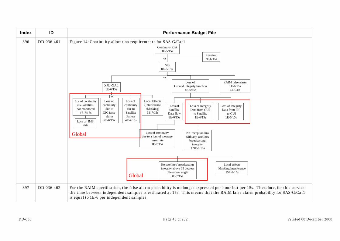
DD-036 Page 46 of 232 Printed 08 December 2000
Index
396
397
ID
DD-036-461
DD-036-462
Performance Budget File
Figure 14: Continuity allocation requirements for SAS-G/Cat1
SIS8E-6/15s
XPL>XAL3E-6/15s
Loss of continuity
due toSatelliteFailure
4E-7/15s
Loss of continuity
due toGIC false
alarm2E-6/15s
Los of continuitydue satellites not monitored
1E-7/15s
Loss of IMS data
RAIM false alarm1E-6/15s2.4E-4/h
Loss of Ground Integrity function
4E-6/15s
No satellites broadcasting integrity above 25 degrees
Elevation angle4E-7/15s
Loss ofsatellite
Data flow2E-6/15s
Loss of IntegrityData from IPF
to GUI1E-6/15s
Loss of IntegrityData from GUI
to Satellite1E-6/15s
No reception linkwith any satellites
broadcasting integrity
1.9E-6/15s
Loss of continuitydue to a loss of message
error rate1E-7/15s
Local effectsMasking/Interference
15E-7/15s
Receiver2E-6/15s
Continuity Risk1E-5/15s
Local Effects(Interference
/Masking)5E-7/15s
or
or
or
Global
Global
For the RAIM specification, the false alarm probability is no longer expressed per hour but per 15s. Therefore, for this servicethe time between independent samples is estimated at 15s. This means that the RAIM false alarm probability for SAS-G/Cat1is equal to 1E-6 per independent samples.

DD-036 Page 47 of 232 Printed 08 December 2000
Index
398
399
400
401
402
403
404
405
406
407
408
409
410
ID
DD-036-463
DD-036-464
DD-036-465
DD-036-466
DD-036-467
DD-036-468
DD-036-469
DD-036-470
DD-036-471
DD-036-472
DD-036-473
DD-036-474
DD-036-475
Performance Budget File
For the loss of continuity due to bit error rate the situation comparing to CAS1-G and SAS-G/NPA is different. Indeed the TTAfor the SAS-G/Cat1 service is equal to 6 seconds comparing to 10s for the other services. Therefore, the TTA budget allocated tothe signal is equal to 1 second instead of 4. However, as shown in the integrity risk allocation tree, if the probability to loose amessage is less than 5 10-4, the loss of one message does not threaten the user integrity. Therefore loosing one message is notevent that will interrupt the service. Otherwise, the requirement on the loss of message would be equal to 6 10-9 which isbarely compatible with what is possible to do. However, the loss of two messages will lead to a non continuity event.
RQ-Gl The probability to loose the SAS-G/Cat1 global navigation function because of a failure or a malfunction on the globalnavigation or integrity function shall be less 2.5E-7/15s.
RQ-Gl The probability to loose the SAS-G/Cat1 global integrity function because of the loss of data flow within the globalintegrity function shall be less than 2E-6/15s
RQ-Gl The probability to loose the SAS-G/Cat1 global integrity function because of the fact that the user has no longer anysatellites above 25 degrees elevation angle broadcasting integrity shall be less than 4E-7/15s.
RQ-Rx The probability to use the SAS-G/Cat1 service because of a failure in the user terminal shall be less than 2E-6/15s
RQ-Sg The probability to use the SAS-G/Cat1 service because of a loss of message shall be less than 1E-7/15s
4.7.12 Continuity Performance Allocation for SAS-GS/Cat1
RQ-Gl The probability to loose the SAS-GS/Cat1 global navigation function because of a failure or a malfunction on the globalnavigation or integrity function shall be less 2.5E-7/15s.
RQ-Gl The probability to loose the SAS-GS/Cat1 global integrity function because of the loss of data flow within the globalintegrity function shall be less than 2E-6/15s
RQ-Gl The probability to loose the SAS-GS/Cat1 global integrity function because of the fact that the user has no longer anysatellites above 25 degrees elevation angle broadcasting integrity shall be less than 4E-7/15s.
RQ-Rx The probability to use the SAS-GS/Cat1 service because of a failure in the user terminal shall be less than 2E-6/15s
RQ-Sg The probability to use the SAS-GS/Cat1 service because of a loss of message shall be less than 1E-7/15s
4.7.13 Continuity Performance Allocation for GAS-G

DD-036 Page 48 of 232 Printed 08 December 2000
Index
411
412
413
414
415
416
417
418
419
420
421
422
423
424
ID
DD-036-476
DD-036-477
DD-036-478
DD-036-479
DD-036-480
DD-036-481
DD-036-482
DD-036-483
DD-036-484
DD-036-485
DD-036-486
DD-036-487
DD-036-488
DD-036-489
Performance Budget File
The allocation for GAS-G are identical to the one made for SAS-G/Cat1.
RQ-Gl The probability to loose the GAS-G global navigation function because of a failure or a malfunction on the globalnavigation or integrity function shall be less 2.5E-7/15s.
RQ-Gl The probability to loose the GAS-G global integrity function because of the loss of data flow within the global integrityfunction shall be less than 2E-6/15s
RQ-Gl The probability to loose the GAS-G global integrity function because of the fact that the user has no longer any satellitesabove 25 degrees elevation angle broadcasting integrity shall be less than 4E-7/15s.
RQ-Rx The probability to use the GAS-G service because of a failure in the user terminal shall be less than 2E-6/15s
RQ-Sg The probability to use the GAS-G service because of a loss of message shall be less than 1E-7/15s
4.7.14 Continuity Performance Allocation for GAS-GS
RQ-Gl The probability to loose the GAS-GS global navigation function because of a failure or a malfunction on the globalnavigation or integrity function shall be less 2.5E-7/15s.
RQ-Gl The probability to loose the GAS-GS global integrity function because of the loss of data flow within the global integrityfunction shall be less than 2E-6/15s
RQ-Gl The probability to loose the GAS-GS global integrity function because of the fact that the user has no longer anysatellites above 25 degrees elevation angle broadcasting integrity shall be less than 4E-7/15s.
RQ-Rx The probability to use the GAS-GS service because of a failure in the user terminal shall be less than 2E-6/15s
RQ-Sg The probability to use the GAS-GS service because of a loss of message shall be less than 1E-7/15s
4.7.15 Availability Performance Allocation for CAS1-G service
Availability is representative of a long term reliability of the system. Therefore an availability tree will put only requirementson the physic entity that provided the function and not on the function itself. The following tree shows how the systemavailability is allocated between the elements of the global component. However those figures are provided only for informationsince it is not the task of GALA to provide such information.

DD-036 Page 49 of 232 Printed 08 December 2000
Index
425
426
427
428
429
430
431
432
433
434
435
ID
DD-036-490
DD-036-491
DD-036-492
DD-036-493
DD-036-494
DD-036-495
DD-036-496
DD-036-497
DD-036-498
DD-036-499
DD-036-501…
Performance Budget File
RQ-Gl The unavailability of the SIS CAS1-G service due to the global navigation function has to be less than 9E-3. Thisincludes the unavailability of:
- Accuracy in horizontal and vertical
- Integrity provided by RAIM/AAIM in horizontal and vertical with 1.25E-4 (NCDP) miss detection probability on eachdimension and 5E-6 (NCDP)false alarm probability on each dimension
- Integrity provided by GIC
- GIC protection level (fault free case) protecting the end user with a risk of 2.5E-8/h on each dimension smaller than the alarmlimit .
- Continuity risk of 4E-6/h
RQ-Gl The unavailability of the SIS CAS1-G service due to the global integrity function has to be less than 1E-3. Thisincludes the unavailability of:
- two MEO satellites broadcasting integrity information
- with a continuity risk of 4E-5/h
False alarm probability requirements are deducted from continuity performance allocation whereas miss detection performancerequirement are deducted from the integrity performance allocation.
Figure 15: Availability Allocation for CAS1-G service

DD-036 Page 50 of 232 Printed 08 December 2000
Index
436
437
438
ID
…DD-036-501
DD-036-502
DD-036-503
DD-036-504
Performance Budget File
Unavailability1E-2
ReceiverNot included in Perf budget
SIS1E-2
Nav messageout of date
1E-3
GeometryXPL<Alarm limit
8E-3
Integritychannel not available
1E-3
N Satellitesfailure
N satellite failureAvailability
N satellite failurestate probability
N satelliteSatellite Failure
N Satellite not monitored
IMS failure
Transmission IMS-IPF failure
Integrity messagebroadcast
unavailability5E-4
Integrity messagegeneration
unavailability5E-4
IPF to GUItransmissionunavailability
GUI to USERtransmission unavailability
OSS
OSPF
GWAN
ULS
GLOBAL
or
or
4.7.16 Availability Performance Allocation for CAS1-GS service
RQ-Gl The unavailability of the SIS CAS1-GS service due to the global navigation function has to be less than 9E-3. Thisincludes the unavailability of:
- Accuracy in horizontal and vertical

DD-036 Page 51 of 232 Printed 08 December 2000
Index
439
440
441
442
443
444
445
446
447
448
449
450
451
452
453
ID
DD-036-505
DD-036-506
DD-036-507
DD-036-508
DD-036-509
DD-036-510
DD-036-511
DD-036-512
DD-036-513
DD-036-514
DD-036-515
DD-036-516
DD-036-517
DD-036-518
DD-036-519
Performance Budget File
- Integrity provided by RAIM/AAIM in horizontal and vertical with 1.25E-4 (NCDP) miss detection probability on eachdimension and 5E-6 (NCDP)false alarm probability on each dimension
- Integrity provided by GIC
- GIC protection level (fault free case) protecting the end user with a risk of 2.5E-8/h on each dimension smaller than the alarmlimit .
- Continuity risk of 4E-6/h
RQ-Gl The unavailability of the SIS CAS1-GS service due to the global integrity function has to be less than 1E-3. Thisincludes the unavailability of
- two MEO satellites broadcasting integrity information
- with a continuity risk of 4E-5/h
4.7.17 Availability Performance Allocation for SAS-G/NPA service
Using the same approach than for CAS1-G service the following requirements on the global component are derived:
RQ-Gl The unavailability of the SIS SAS-G/NPA service due to the global navigation function has to be less than 9E-4. Thisincludes the unavailability of:
- Accuracy in horizontal and vertical
- Integrity provided by RAIM/AAIM in vertical with 2.5E-4 (NCDP) miss detection probability on each dimension and 2E-7(NCDP) false alarm probability on each dimension
- Integrity provided by GIC
- GIC protection level (fault free case) protecting the end user with a risk of 5E-8/h on each dimension smaller than the alarmlimit .
- With a continuity risk of 1E-8/h
DD-036 Page 52 of 232 Printed 08 December 2000
Index
454
455
456
457
458
459
460
461
462
463
464
465
466
467
468
469
ID
DD-036-520
DD-036-521
DD-036-522
DD-036-523
DD-036-524
DD-036-525
DD-036-526
DD-036-527
DD-036-528
DD-036-529
DD-036-530
DD-036-531
DD-036-532
DD-036-533
DD-036-534
DD-036-535
Performance Budget File
RQ-Gl The unavailability of the SIS SAS-G/NPA service due to the global integrity function has to be less than 1E-4. Thisincludes the unavailability of:
- two MEO satellites broadcasting integrity information
- with a continuity risk of 6E-6/h
4.7.18 Availability Performance Allocation for SAS-G/Cat1 service
The strategy to deduct availability requirements is the same as the one explained above for CAS1-G.
RQ-Gl The unavailability of the SIS SAS-G/Cat1 service due to the global navigation function has to be less than 9E-3. Thisincludes the unavailability of:
- Accuracy in horizontal and vertical
- Integrity provided by RAIM/AAIM in horizontal and vertical with 6.25E-3 (NCDP) miss detection probability on eachdimension and 5E-7 (NCDP) false alarm probability on each dimension
- Integrity provided by GIC
- GIC protection level (fault free case) protecting the end user with a risk of 5E-8/150s on each dimension smaller than thealarm limit .
- And a continuity risk lower than 4E-7/15s
RQ-Gl The unavailability of the SIS SAS-G/Cat1 service due to the global integrity function has to be less than 1E-3. Thisincludes the unavailability of:
- two MEO satellites broadcasting integrity information
- with an continuity risk of 2.4E-6/15s
4.7.19 Availability Performance Allocation for SAS-GS/Cat1 service
RQ-Gl The unavailability of the SIS SAS-GS/Cat1 service due to the global navigation function has to be less than 9E-4. Thisincludes the unavailability of:

DD-036 Page 53 of 232 Printed 08 December 2000
Index
470
471
472
473
474
475
476
477
478
479
480
481
482
483
484
485
ID
DD-036-536
DD-036-537
DD-036-538
DD-036-539
DD-036-540
DD-036-541
DD-036-542
DD-036-543
DD-036-544
DD-036-545
DD-036-546
DD-036-547
DD-036-548
DD-036-549
DD-036-550
DD-036-551
Performance Budget File
- Accuracy in horizontal and vertical
- Integrity provided by RAIM/AAIM in horizontal and vertical with 6.25E-3 (NCDP) miss detection probability on eachdimension and 5E-7 (NCDP) false alarm probability on each dimension
- Integrity provided by GIC
- GIC protection level (fault free case) protecting the end user with a risk of 5E-8/150s on each dimension smaller than thealarm limit .
- And a continuity risk lower than 4E-7/15s
RQ-Gl The unavailability of the SIS SAS-GS/Cat1 service due to the global integrity function has to be less than 1E-4. Thisincludes the unavailability of
- two MEO satellites broadcasting integrity information
- with an continuity risk of 2.4E-6/15s
4.7.20 Availability Performance Allocation for GAS-G service
The strategy to deduct availability requirements is the same as the one explained above for CAS1-G.
RQ-Gl The unavailability of the SIS GAS-G service due to the global navigation function has to be less than 9E-3. Thisincludes the unavailability of:
- Accuracy in horizontal and vertical
- Integrity provided by RAIM/AAIM in horizontal and vertical with 6.25E-3 (NCDP) miss detection probability on eachdimension and 5E-7 (NCDP) false alarm probability on each dimension
- Integrity provided by GIC
- GIC protection level (fault free case) protecting the end user with a risk of 5E-8/150s on each dimension smaller than thealarm limit .
- And a continuity risk lower than 4E-7/15s

DD-036 Page 54 of 232 Printed 08 December 2000
Index
486
487
488
489
490
491
492
493
494
495
496
497
498
499
500
501
ID
DD-036-552
DD-036-553
DD-036-554
DD-036-555
DD-036-556
DD-036-557
DD-036-558
DD-036-559
DD-036-560
DD-036-561
DD-036-562
DD-036-563
DD-036-564
DD-036-565
DD-036-566
DD-036-567
Performance Budget File
RQ-Gl The unavailability of the SIS GAS-G service due to the global integrity function has to be less than 1E-3. This includesthe unavailability of:
- two MEO satellites broadcasting integrity information
- with an continuity risk of 2.4E-6/15s
4.7.21 Availability Performance Allocation for GAS-GS service
The strategy to deduct availability requirements is the same as the one explained above for CAS1-G.
RQ-Gl The unavailability of the SIS GAS-GS service due to the global navigation function has to be less than 9E-4. Thisincludes the unavailability of:
- Accuracy in horizontal and vertical
- Integrity provided by RAIM/AAIM in horizontal and vertical with 6.25E-3 (NCDP) miss detection probability on eachdimension and 5E-7 (NCDP) false alarm probability on each dimension
- Integrity provided by GIC
- GIC protection level (fault free case) protecting the end user with a risk of 5E-8/150s on each dimension smaller than thealarm limit .
- And a continuity risk lower than 4E-7/15s
RQ-Gl The unavailability of the SIS GAS-GS service due to the global integrity function has to be less than 1E-3. Thisincludes the unavailability of
- two MEO satellites broadcasting integrity information
- with an continuity risk of 2.4E-6/15s
4.8 Global Navigation Function + Regional Integrity Function
4.8.1 SAS-R service provision

DD-036 Page 55 of 232 Printed 08 December 2000
Index
502
503
504
ID
DD-036-568
DD-036-569
DD-036-571
Performance Budget File
The SAS-R service provides to the region a way to handle integrity information on their own zone. Therefore the region cantake responsibility for what happens on its zone of coverage. As far as performance are concerned, SAS-R service is equivalentto SAS-G/Cat1. Since the SAS-G/Cat1 global service is provided by Europe, there is no need to have a regional component onEurope to provide SAS-R service. On the other hand, for regions outside Europe, even if there is an world wide infra-structureallowing to get SAS-R like performance, the deployment of a regional component is necessary. This regional component willallow the region to have complete control on the integrity information broadcast on the region
The difference between SAS-G/Cat1 and SAS-R is that the integrity function is now mainly insured by the region. ForSAS-G/Cat1 service the allocation was stopped at high level since the same entity (ESA/GalileoSat) is responsible of thedevelopment of all the elements supporting the integrity function. For regional service, the situation is different. Thecollection of information, the integrity determination and part of integrity dissemination is supported by the regionalcomponent. The broadcast of the information is supported by the global component. Outside Europe, navigation and integrityfunction are not under the same entity responsibility. Therefore, it is necessary to go a step forward in the allocation in order toclearly specify the contribution of the regional and global component to the navigation and integrity function.
Figure 16: SAS-R service provision
SAS REGIONALCOMPONENT
SAS REGIONALCOMPONENT
SAS REGIONALCOMPONENT
SAS REGIONALCOMPONENT
SAS REGIONAL COMPONENT
SAS REGIONAL COMPONENT
SAS GLOBAL COMPONENTSAS GLOBAL COMPONENT
SAS-R EuropeSAS-R Region 1 SAS-R Region 2 SAS-R Region 3

DD-036 Page 56 of 232 Printed 08 December 2000
Index
505
506
507
508
ID
DD-036-572
DD-036-573
DD-036-575
DD-036-576
Performance Budget File
4.8.2 Integrity Performance Allocation for SAS-R service
The following tree details the risk allocation between the global and regional component of the system.
Figure 17: Integrity Risk Allocation for SAS-R serviceUndetected Globalsingle SIS by GIC
5E-8/150s
Global Single SIS
4E-6/150s
GIC single failure miss detection
7.5E-3
Invalid SISA At SV output4E-8/150s
Satellite not monitored not flaggedNegligible
Miss transmissionof Alert within TTA
7.5E-3
Satellitefailure
4E-6/150s
Miss Detectionwithin T1*
5E-3
Transmission failurewithin T2*2.5E10-3
Transmissionfrom IPF to GUI
1E-3
Transmission fromGUI to User
1E-3
Integrity message loss due to bit error
rate5E-4
Transmission delay
Data corruption
Transmission delay
Data corruption
*T1=Allocated budget for detectionT2=Allocated budget for transmissionTTA=T1+T2
Global
Regional Global
and
or or
or
or
oror
Corruption of validSISA in SIS2E-8/150s
The 6 seconds time to alarm requirement is allocated as follows between the different components of the system. The system issupposed synchronous. The RUI, GUI and ULF are assumed to be in the same facility which is the ULS (up-link station).
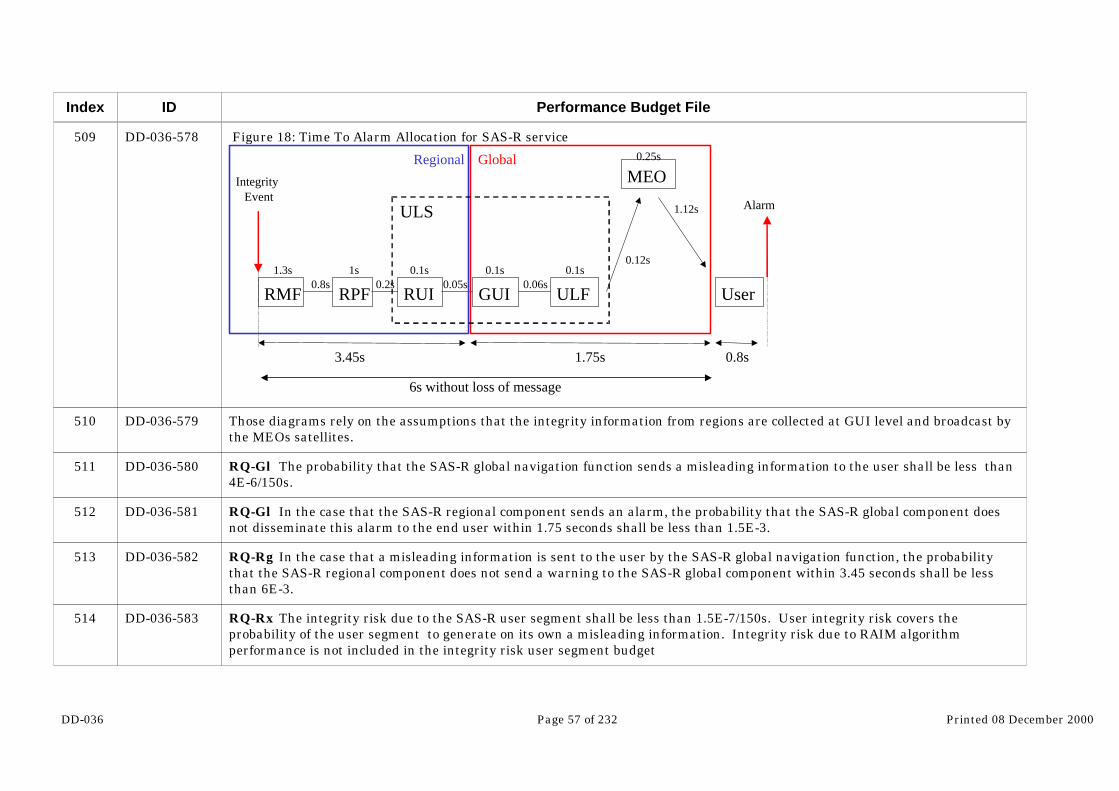
DD-036 Page 57 of 232 Printed 08 December 2000
Index
509
510
511
512
513
514
ID
DD-036-578
DD-036-579
DD-036-580
DD-036-581
DD-036-582
DD-036-583
Performance Budget File
Figure 18: Time To Alarm Allocation for SAS-R service
RMF RPF RUI GUI ULF
MEO
User
Integrity Event
Global
0.8s
Alarm
1.3s0.8s
1s0.2s
0.1s0.05s
Regional
0.1s0.06s
0.1s0.12s
0.25s
1.12s
3.45s 1.75s
ULS
6s without loss of message
Those diagrams rely on the assumptions that the integrity information from regions are collected at GUI level and broadcast bythe MEOs satellites.
RQ-Gl The probability that the SAS-R global navigation function sends a misleading information to the user shall be less than4E-6/150s.
RQ-Gl In the case that the SAS-R regional component sends an alarm, the probability that the SAS-R global component doesnot disseminate this alarm to the end user within 1.75 seconds shall be less than 1.5E-3.
RQ-Rg In the case that a misleading information is sent to the user by the SAS-R global navigation function, the probabilitythat the SAS-R regional component does not send a warning to the SAS-R global component within 3.45 seconds shall be lessthan 6E-3.
RQ-Rx The integrity risk due to the SAS-R user segment shall be less than 1.5E-7/150s. User integrity risk covers theprobability of the user segment to generate on its own a misleading information. Integrity risk due to RAIM algorithmperformance is not included in the integrity risk user segment budget
DD-036 Page 58 of 232 Printed 08 December 2000
Index
515
516
517
518
519
520
521
522
523
524
525
526
527
ID
DD-036-584
DD-036-585
DD-036-586
DD-036-587
DD-036-588
DD-036-589
DD-036-590
DD-036-591
DD-036-592
DD-036-593
DD-036-594
DD-036-595
DD-036-596
Performance Budget File
RQ-Rx The time elapsed between the moment when an alarm arrives at the SAS-R receiver and the alarm is displayed to theuser shall not exceed 0.8s
RQ-Sg The probability to loose an integrity message due to bit error rate on the SAS-R signal in space shall be less than 5E-4.
RQ-Sg The probability that the an HMI is generated within the SAS-R navigation message due to bit error rate shall be lessthan 2 10-8/150s
4.8.3 Integrity performance allocation for SAS-RM service
RQ-Gl The probability that the SAS-RM global navigation function sends a misleading information to the user shall be less than 4E-6/150s.
RQ-Gl In the case that the SAS-RM regional component sends an alarm, the probability that the SAS-RM global componentdoes not disseminate this alarm to the end user within 1.75 seconds shall be less than 1.5E-3.
RQ-Rg In the case that a misleading information is sent to the user by the SAS-RM global navigation function, the probabilitythat the SAS-RM regional component does not send a warning to the SAS-RM global component within 3.45 seconds shall beless than 6E-3.
RQ-Rx The integrity risk due to the SAS-RM user segment shall be less than 1.5E-7/150s. User integrity risk covers theprobability of the user segment to generate on its own a misleading information. Integrity risk due to RAIM algorithmperformance is not included in the integrity risk user segment budget
RQ-Rx The time elapsed between the moment when an alarm arrives at the SAS-RM receiver and the alarm is displayed to theuser shall not exceed 0.8s
RQ-Sg The probability to loose an integrity message due to bit error rate on the SAS-RM signal in space shall be less than5E-4.
RQ-Sg The probability that the an HMI is generated within the SAS-RM navigation message due to bit error rate shall be lessthan 2 10-8/150s
4.8.4 Continuity Performance Allocation for SAS-R
The following tree represents the allocation of continuity risk between the system components. The first step is to allocatebetween the receiver and the SIS.

DD-036 Page 59 of 232 Printed 08 December 2000
Index
528
529
ID
DD-036-597
DD-036-598
Performance Budget File
The first arm on the SIS part is an allocation on the geometry. A degradation of the geometry during an approach can be due toa loss of one or several satellites. The rest of the budget is allocated to the RAIM false alarm and the loss of integrity function. Concerning the RAIM false alarm, it is interesting to note that the specification if again much less stringent than for RAIM usedon global basis. This will improve the RAIM availability performance.
The loss of the integrity function can be due to loss of global or regional component. Therefore, the tree is developed until thedistinction between specifications on global and regional components can be identified.
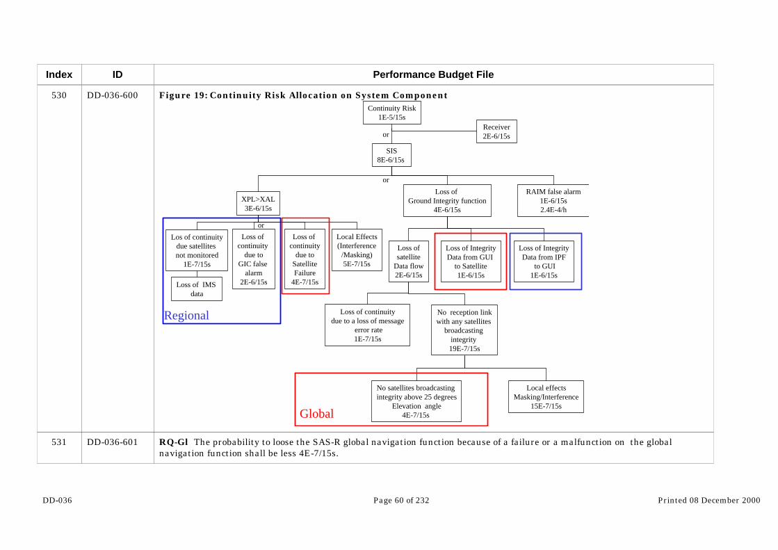
DD-036 Page 60 of 232 Printed 08 December 2000
Index
530
531
ID
DD-036-600
DD-036-601
Performance Budget File
Figure 19: Continuity Risk Allocation on System Component
SIS8E-6/15s
XPL>XAL3E-6/15s
Loss of continuity
due toSatelliteFailure
4E-7/15s
Loss of continuity
due toGIC false
alarm2E-6/15s
Los of continuitydue satellites not monitored
1E-7/15s
Loss of IMS data
RAIM false alarm1E-6/15s2.4E-4/h
Loss of Ground Integrity function
4E-6/15s
No satellites broadcasting integrity above 25 degrees
Elevation angle4E-7/15s
Loss ofsatellite
Data flow2E-6/15s
Loss of IntegrityData from IPF
to GUI1E-6/15s
Loss of IntegrityData from GUI
to Satellite1E-6/15s
No reception linkwith any satellites
broadcasting integrity 19E-7/15s
Loss of continuitydue to a loss of message
error rate1E-7/15s
Local effectsMasking/Interference
15E-7/15s
Receiver2E-6/15s
Continuity Risk1E-5/15s
Local Effects(Interference
/Masking)5E-7/15s
or
or
or
Regional
Global
RQ-Gl The probability to loose the SAS-R global navigation function because of a failure or a malfunction on the globalnavigation function shall be less 4E-7/15s.

DD-036 Page 61 of 232 Printed 08 December 2000
Index
532
533
534
535
536
537
538
539
540
541
542
543
544
545
ID
DD-036-602
DD-036-603
DD-036-604
DD-036-605
DD-036-606
DD-036-607
DD-036-608
DD-036-609
DD-036-610
DD-036-611
DD-036-612
DD-036-613
DD-036-614
DD-036-615
Performance Budget File
RQ-Gl The probability to loose the SAS-R integrity function because of the interruption of the data flow within the globalcomponent shall be less than 1.4E-6/15s
RQ-Rg The probability to loose the SAS-R global navigation function due to a failure or a malfunction of the regionalcomponent shall be less d 2.1E-6/15s
RQ-Rg The probability to loose the SAS-R integrity function because of the interruption of integrity information provision bythe regional component shall be less than 1E-6/15s
RQ-Rx The probability of failure of the SAS-R user segment shall not exceed 2E-6/15s
RQ-Sg The probability to loose the SAS-R service because of a loss of message shall be less than 1E-7/15s
4.8.5 Continuity performance allocation for SAS-RM
RQ-Gl The probability to loose the SAS-RM global navigation function because of a failure or a malfunction on the globalnavigation function shall be less 4E-7/15s.
RQ-Gl The probability to loose the SAS-RM integrity function because of the interruption of the data flow within the globalcomponent shall be less than 1.4E-6/15s
RQ-Rg The probability to loose the SAS-RM global navigation function due to a failure or a malfunction of the regionalcomponent shall be less d 2.1E-6/15s
RQ-Rg The probability to loose the SAS-RM integrity function because of the interruption of integrity information provision bythe regional component shall be less than 1E-6/15s
RQ-Rx The probability of failure of the SAS-RM user segment shall not exceed 2E-6/15s
RQ-Sg The probability to loose the SAS-RM service because of a loss of message shall be less than 1E-7/15s
4.8.6 Availability Performance Allocation for SAS-R
As for the other services and still because it appears difficult to specify a MTTR (Mean Time To Repair) for a receiver, thereceiver is nor included in the availability performance budget. Therefore the availability is split between the navigationfunction and the integrity function.
DD-036 Page 62 of 232 Printed 08 December 2000
Index
546
547
548
549
550
551
552
553
554
555
556
557
ID
DD-036-616
DD-036-617
DD-036-618
DD-036-619
DD-036-620
DD-036-621
DD-036-622
DD-036-623
DD-036-624
DD-036-625
DD-036-626
DD-036-628…
Performance Budget File
For the unavailability due to a lack of geometry, it is difficult to split the allocation between global and regional. Indeed, bothcomponents impact this budget. The loss of one satellite can be due either to a satellite failure or to the fact that the satellite isno longer monitored. This second event will come from the loss of a IMS from the IPF point of view (i.e.: loss of a IMS or loss ofthe link IMS-IPF). One solution is to make sure in the design of the regional component that the impact of a loss of one orseveral IMS is negligible on the global system availability.
RQ-Gl The unavailability of the SIS SAS-R service due to global navigation function shall be less than 9E-3. This includesthe availability of:
- Accuracy in horizontal and vertical
- Integrity provided by RAIM/AAIM in horizontal and vertical with 6.25E-3 (NCDP) miss detection probability on eachdimension and 5E-7 (NCDP) false alarm probability on each dimension
- Integrity provided by GIC
- GIC protection level (fault free case) protecting the end user with a risk of 5E-8/150s on each dimension smaller than thealarm limit
- Continuity with a continuity risk of 4E-7/15s
RQ-Gl The unavailability of the SAS-R integrity broadcast function insured by the global segment shall not be less than 2E-4. To be available this function shall provide:
- Two MEO’s above 25 degrees broadcasting integrity
- With a continuity risk of 1E-6/15s
RQ-Rg The unavailability of the SAS-R integrity determination and dissemination function insured by the regional component shall be less than 8E-4 with a continuity risk of 1E-6/15s
Figure 20: Availability Allocation between Global and Regional component for SAS-R

DD-036 Page 63 of 232 Printed 08 December 2000
Index
558
559
560
561
ID
…DD-036-628
DD-036-629
DD-036-630
DD-036-631
DD-036-632
Performance Budget File
Unavailability1E-2
ReceiverNot included in Perf budget
SIS1E-2
Nav messageout of date
1E-3
GeometryXPL<Alarm limit
8E-3Integrity
channel not available1E-3
Loss ofN satellites
N satellite lossAvailability
N satellite lossstate probability
N satelliteSatellite Failure
Integrity messagebroadcast
failure5E-4
Integrity messagegeneration failure
5E-4
IPF to GUItransmission
failure3E-4
GUI to USERtransmission
failure2E-4
OSS
OSPF
GWAN
ULS
N Satellite not monitored
Negligible
IMS failure
Transmission IMS-IPF failure
4.8.7 Availability performance allocation for SAS-RM service
RQ-Gl The unavailability of the SIS SAS-RM service due to global navigation function shall be less than 9E-4. This includesthe availability of:
- Accuracy in horizontal and vertical
- Integrity provided by RAIM/AAIM in horizontal and vertical with 6.25E-3 (NCDP) miss detection probability on eachdimension and 5E-7 (NCDP) false alarm probability on each dimension
DD-036 Page 64 of 232 Printed 08 December 2000
Index
562
563
564
565
566
567
568
569
570
571
572
ID
DD-036-633
DD-036-634
DD-036-635
DD-036-636
DD-036-637
DD-036-638
DD-036-639
DD-036-640
DD-036-641
DD-036-642
DD-036-643
Performance Budget File
- Integrity provided by GIC
- GIC protection level (fault free case) protecting the end user with a risk of 5E-8/150s on each dimension smaller than thealarm limit
- Continuity with a continuity risk of 4E-7/15s
RQ-Gl The unavailability of the SAS-RM integrity broadcast function insured by the global segment shall not be less than2E-5. To be available this function shall provide
- Two MEO’s above 25 degrees broadcasting integrity
- With a continuity risk of 1E-6/15s
RQ-Rg The unavailability of the SAS-R integrity determination and dissemination function insured by the regional component shall be less than 8E-5 with a continuity risk of 1E-6/15s
4.8.8 EGNOS service provision
Regional European service such as SAS-R or SAS-RM are provided by the Galileo global component. Since the globalcomponent is under European responsibility, there is no need to set up a regional infrastructure for responsibility and liabilitypurpose. However, through the integration of EGNOS, Galileo provides additional specific regional services on ECAC (EGNOS1/2/3A/3B/3C). The allocation for those services is already available in the design document of EGNOS and will not be recalledin this document.
4.9 Global Navigation functions + Local functions
Five services use the global together with a local component: CAS1-L1/2/3, SAS-L and GAS-L. For local services the line is clearbetween global and local component. The global component impacts only the geometry. For the UERE and the integrityfunction, it is mainly driven by the local components. Generally, what can be said is that it appears difficult at this stage tomake an allocation between global and local since the architecture from one local component to the other might be very different[RD-010]. It depends whether, pseudolite, local corrections, interference detectors are used. The allocation may also be changedaccording to the fact that the local corrections are broadcast by a local communication link or though the MEO’s (CAS1-L2). Nevertheless, it makes sense to assume that the local service will provide the same type of basic function that have beenidentified in the other services, Global or Regional.

DD-036 Page 65 of 232 Printed 08 December 2000
Index
573
574
575
576
577
578
579
580
581
582
583
584
585
ID
DD-036-644
DD-036-645
DD-036-646
DD-036-647
DD-036-648
DD-036-649
DD-036-650
DD-036-651
DD-036-652
DD-036-653
DD-036-654
DD-036-655
DD-036-657…
Performance Budget File
Those function are:
- Navigation function
- Correction and integrity determination function
- Correction and integrity broadcast function
The following trees give a preliminary allocation for integrity, continuity and availability between local and global component.
4.9.1 Integrity Performance Allocation for CAS1-L1
As for the local architecture, the way to derive local integrity to the end user is not totally defined yet. In order to make apreliminary performance apportionment on the local component, the protocol described in the MASP (Minimum requirementsfor receiver to be used in local differential conditions for civil aviation procedures [RD-019]). It can be summarized as follows:
The local station sends to the user:
- Differential correction
- UDRE like parameter allowing the user to compute a protection level under the assumption that the system is fault free(assumption H0)
- Bias parameters that allow the user to compute protection levels assuming a failure on one receiver among all present in thelocal station (assumption H1).
The final user protection is the largest among the ones computed. Therefore the system is designed to cope with one receiverfailure. A satellite failure does not induce an integrity risk for a local service as long as the differential corrections are updatedwithin the TTA (each second). Therefore the events that could threaten the user integrity are more than one undetectedreceiver failure in the local station or a failure in the data broadcast.
Figure 21: Integrity Risk Allocation between global and local component for CAS1-L1

DD-036 Page 66 of 232 Printed 08 December 2000
Index ID
…DD-036-657
Performance Budget File
Total SystemIntegrity risk
2E-7/h
Receiver1E-7/h
SIS1E-7/h
XNSE>XPLunder H0 and H1
5E-8/h
XNSE>XPLunder H0
XNSE>XPLunder H1
Integrity failure due to other source than H0 and H1
5E-8/h
Undetected failure frommore than 1 reference Rx
Erroneous correctionsent to the user
Undetected localevents by RAIM
or
orCorrection
and integritydetermination
3E-8/h
Correction and integrity
broadcast2E-8/h
Local

DD-036 Page 67 of 232 Printed 08 December 2000
Index
586
587
588
589
590
591
ID
DD-036-658
DD-036-659
DD-036-660
DD-036-661
DD-036-663
DD-036-664
Performance Budget File
As usual the budget is first split between receiver and SIS. Here, the same comment made is CAS1 global service can berepeated. The integrity risk allocation put on the receiver appears very stringent for a service that is not safety criticaloriented.
The budget SIS is split between two components. The first case is a kind of “fault free” situation. It includes the situation forwhich the system has been designed. Those situation include the “fault-free state” (H0) and the “single reference receiverfailure state” (H1). Two protection levels are computed at user level [RD-07] to protect him in those two situations.
The second part of the SIS risk budget is allocated to the generation and transmission of the differential corrections. Those twofunctions are normally performed by the local component’ at least for SAS. However, in GALA the possibility of broadcasting thelocal information through the MEO’s for CAS1-L2 has been mentioned. In this case the part of the risk allocated to the localcomponent should be put on the transmission link. In that case, if integrity is really required for this kind of service, therequirement induces by local services on the global component will be more stringent than the ones coming from global andregional services. CAS1 bit error rate will be also impacted.
As far as TTA is concerned the following allocation can be made:
Figure 22: Time To Alert Allocation for CAS1-L1 service
Integrity Event
Pseudo-rangemeasurement
User TerminalLocal Rx
Corrupted pseudo-range
Alarm reception
TTA=1s
AlarmDisplayed
1s 0.5s0.5s
The following requirements can be deduced from the preceding performance allocation tree.

DD-036 Page 68 of 232 Printed 08 December 2000
Index
592
593
594
595
596
597
598
599
600
601
602
ID
DD-036-665
DD-036-666
DD-036-667
DD-036-668
DD-036-669
DD-036-670
DD-036-671
DD-036-672
DD-036-673
DD-036-674
DD-036-675
Performance Budget File
RQ-Lc The probability that local correction and integrity determination function generates an hazardous misleadinginformation due to a event not covered by H0 and H1 state without being corrected within the 0.5 second shall be less than5E-8/h for CAS1-L1 service.
RQ-Rx The integrity risk due to the user segment shall be less than 1E-7/h for CAS1-L1 service. User integrity risk covers theprobability of the user segment to generate on its own a misleading information. Integrity risk due to potential use of RAIMalgorithm performance is not included in the integrity risk
RQ-Rx The time elapsed between the moment when an alarm arrives at the CAS1-L1 receiver and the alarm is displayed to theuser shall not exceed 0.5s
4.9.2 Integrity performance allocation for SAS-L service
The SAS-L requirements are deducted using the same strategy as the one used for CAS1-L1
RQ-Lc The probability that local correction and integrity determination function generates an hazardous misleadinginformation due to a event not covered by H0 and H1 state without being corrected within 1 second shall be less than5E-10/150s for SAS-L service
RQ-Rx The integrity risk due to the user segment shall be less than 1E-9/150s for SAS-L service. User integrity risk covers theprobability of the user segment to generate on its own a misleading information. Integrity risk due to potential use of RAIMalgorithm performance is not included in the integrity risk
RQ-Rx The time elapsed between the moment when an alarm arrives at the SAS-L receiver and the alarm is displayed to theuser shall not exceed 0.5s
4.9.3 Integrity performance allocation for GAS-L service
The GAS-L mission requirements are similar to the SAS-L ones. Therefore the requirements allocated to the local station andthe user equipment are identical.
RQ-Rg The probability that local correction and integrity determination function generates an hazardous misleadinginformation due to a event not covered by H0 and H1 state without being corrected within the 0.5s shall be less than 5E-10/150sfor GAS-L service
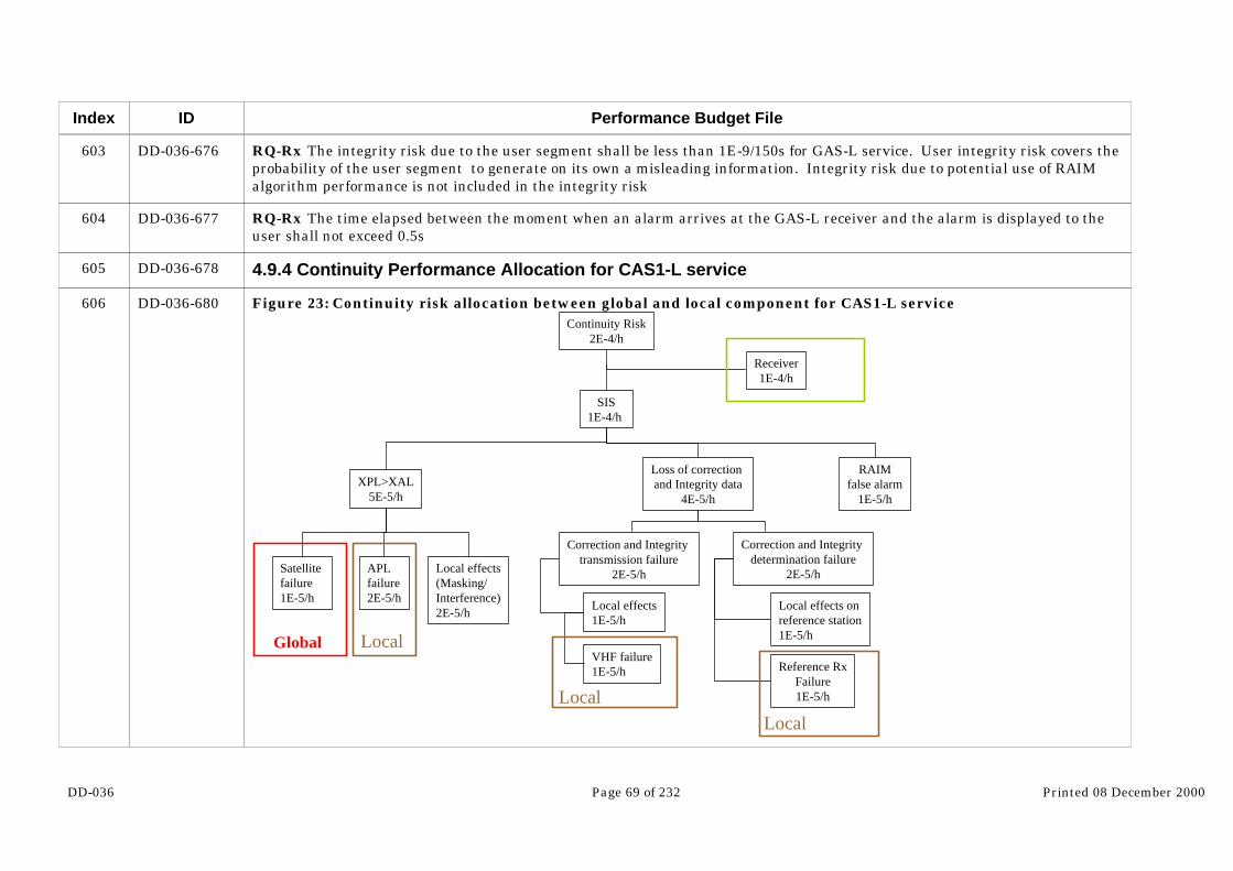
DD-036 Page 69 of 232 Printed 08 December 2000
Index
603
604
605
606
ID
DD-036-676
DD-036-677
DD-036-678
DD-036-680
Performance Budget File
RQ-Rx The integrity risk due to the user segment shall be less than 1E-9/150s for GAS-L service. User integrity risk covers theprobability of the user segment to generate on its own a misleading information. Integrity risk due to potential use of RAIMalgorithm performance is not included in the integrity risk
RQ-Rx The time elapsed between the moment when an alarm arrives at the GAS-L receiver and the alarm is displayed to theuser shall not exceed 0.5s
4.9.4 Continuity Performance Allocation for CAS1-L service
Figure 23: Continuity risk allocation between global and local component for CAS1-L service
SIS1E-4/h
XPL>XAL5E-5/h
RAIMfalse alarm
1E-5/h
Loss of correction and Integrity data
4E-5/h
Receiver1E-4/h
Continuity Risk2E-4/h
Satellite failure1E-5/h
APL failure2E-5/h
Correction and Integrity transmission failure
2E-5/h
Correction and Integrity determination failure
2E-5/h
Local effects on reference station1E-5/h
Reference RxFailure1E-5/h
Local effects1E-5/h
VHF failure1E-5/h
LocalGlobal
Local effects(Masking/Interference)2E-5/h
LocalLocal
DD-036 Page 70 of 232 Printed 08 December 2000
Index
607
608
609
610
611
612
613
614
615
616
617
618
619
620
ID
DD-036-681
DD-036-682
DD-036-683
DD-036-684
DD-036-685
DD-036-686
DD-036-687
DD-036-688
DD-036-689
DD-036-690
DD-036-691
DD-036-692
DD-036-693
DD-036-694
Performance Budget File
For the risk allocated to the geometry, the same problem that arose in regional service to allocate the budget between failed andnot monitored satellite arises again. Geometry is impacted both by the global component through the satellites and the localcomponent through the pseudo-lites.
The rest of the risk is allocated to the generation and transmission of the differential correction data.
RQ-Rx The probability of failure of the user segment shall not exceed 1E-7/h for CAS1-L1 service
RQ-Lc The loss of the navigation function due to a failure or malfunction of the local component shall not exceed 2E-5/h forCAS1-L1 service (navigation function is impacted part by the satellites and part by the pseudolites)
RQ-Lc The loss of the CAS1-L1 correction and integrity determination function due to a failure on the local component shallnot exceed 1E-5/h.
RQ-Lc The loss of the CAS1-L1 correction and integrity dissemination function due to a failure on the local component shallnot exceed 1E-5/h.
4.9.5 Continuity Performance Allocation for SAS-L service
The architecture and requirements for GAS-L service are identical than the ones defined for SAS-L service. Therefore Theprevious requirements allow to deduct the system GAS-L service requirements.
RQ-Rx The probability of failure of the user segment shall not exceed 1E-6/15s for SAS-L service
RQ-Lc The loss of the navigation function due to a failure or malfunction of the local component shall not exceed 5E-7/15s forSAS-L service (navigation function is impacted part by the satellites and part by the pseudolites)
RQ-Lc The loss of the SAS-L correction and integrity determination function due to a failure on the local component shall notexceed 2E-6/15s.
RQ-Lc The loss of the SAS-L correction and integrity dissemination function due to a failure on the local component shall notexceed 2E-6/15s.
4.9.6 Continuity Performance Allocation for GAS-L service
The architecture and requirements for GAS-L service are identical than the ones defined for SAS-L service. Therefore Theprevious requirements allow to deduct the system GAS-L service requirements.

DD-036 Page 71 of 232 Printed 08 December 2000
Index
621
622
623
624
625
626
627
628
629
630
631
632
ID
DD-036-695
DD-036-696
DD-036-697
DD-036-698
DD-036-699
DD-036-700
DD-036-701
DD-036-702
DD-036-703
DD-036-704
DD-036-705
DD-036-707…
Performance Budget File
RQ-Rx The probability of failure of the user segment shall not exceed 1E-6/15s for GAS-L service
RQ-Lc The loss of the navigation function due to a failure or malfunction of the local component shall not exceed 5E-7/15s forGAS-L service (navigation function is impacted part by the satellites and part by the pseudolites)
RQ-Lc The loss of the GAS-L correction and integrity determination function due to a failure on the local component shall notexceed 2E-6/15s.
RQ-Lc The loss of the GAS-L correction and integrity dissemination function due to a failure on the local component shall notexceed 2E-6/15s.
4.9.7 Availability Performance Allocation for CAS1-L service
The following tree allocates the system unavailability between global and local component. As mentioned before and as detailedin the following figure, the availability requirement allocation allows to deduct requirement on the global component and thelocal component.
RQ-Gl The unavailability of the CAS1-L1 navigation function shall be less than 9E-3. This includes the availability of:
- Accuracy in horizontal and vertical
- Integrity: protection level sized for a risk of 2.5E-8/h on each dimension
- Continuity less than 1E5/h
RQ-Lc The unavailability of the CAS1-L1 correction and integrity determination and dissemination function service shall bemore than 1E-3 with a continuity less than 2E-5/h.
Figure 24: Unavailability allocation between Local and Global component for CAS1-L service

DD-036 Page 72 of 232 Printed 08 December 2000
Index
633
634
635
636
637
ID
…DD-036-707
DD-036-708
DD-036-709
DD-036-710
DD-036-711
DD-036-712
Performance Budget File
SIS1E-2
XPL>XAL9E-3
Loss of correction and Integrity data
1E-3
ReceiverNot included in the Perf Budget
Unavailability1E-2
Satellite failure
APL failure
Correction and Integrity transmission failure
3E-7/15s
Correction and Integrity determination unavailability
2E-7/15s
LocalGlobal
Local
4.9.8 Availability Performance Allocation for SAS-L service
The availability performance allocation for SAS-L service are done in the same way used for CAS1-L service at the differencethat SAS-L includes continuity requirements.
RQ-Gl The unavailability of the SAS-L navigation function shall be less than 9E-4. This includes the availability of:
- Accuracy in horizontal and vertical
- Integrity: protection level sized for a risk of 2.5E-10/150s on each dimension

DD-036 Page 73 of 232 Printed 08 December 2000
Index
638
639
640
641
642
643
644
645
646
647
648
649
650
651
652
653
ID
DD-036-713
DD-036-714
DD-036-715
DD-036-716
DD-036-717
DD-036-718
DD-036-719
DD-036-720
DD-036-721
DD-036-722
DD-036-723
DD-036-724
DD-036-725
DD-036-726
DD-036-727
DD-036-728
Performance Budget File
- Continuity with a continuity risk of 1E-6/15s
RQ-Lc The unavailability of the SAS-L correction and integrity determination and dissemination function service shall be morethan 1E-4 with a continuity risk of 4E-6/15s .
4.9.9 Availability Performance Allocation for SAS-L service
The availability performance allocation for GAS-L service is done in the same way used for SAS-L service.
RQ-Gl The unavailability of the GAS-L navigation function shall be less than 9E-4. This includes the availability of:
- Accuracy in horizontal and vertical
- Integrity: protection level sized for a risk of 2.5E-10/150s on each dimension
- Continuity with a continuity risk of 1E-6/15s
RQ-Lc The unavailability of the GAS-L correction and integrity determination and dissemination function service shall bemore than 1E-4 with a continuity risk of 4E-6/15s .
4.10 From Mission to System Requirements
Mission performance requirements is the performance that the user can expect from the "total" system. It means that thisperformance includes all the components that have an impact on the final user performance which are namely:
- Galileo SIS
- Galileo Receiver
- Potential other systems
- Potential other sensors
The first step to identify the system requirements is obviously to determine what element is in the system and which one is not. As a generic rule, we can say that the elements that will be "physically" deployed by "Galileo industry" belong to the system andthe others do not. Following this strategy and as shown in the next document, the elements belonging to the system are:

DD-036 Page 74 of 232 Printed 08 December 2000
Index
654
655
656
657
658
659
660
661
ID
DD-036-729
DD-036-730
DD-036-731
DD-036-732
DD-036-733
DD-036-734
DD-036-735
DD-036-737…
Performance Budget File
- The Galileo global component (GalileoSat + signal)
- The regional components outside Europe
- The local component
One thing that is under discussion is whether or not, components that will be developed outside Europe belong to the system. As far as cost in concerned, it is clear that all that is not European shall be excluded of the system. However, technicallyspeaking, the regional component is part of the global system. Since Galileo is a system that is designed globally, all thecontributions even not European should be included in it (as it is done for GNSS1). For cost matters, it will be more accurate tospeak about the European contribution to Galileo instead of the Galileo cost.
Therefore, now that what is included in the system is identified the second step is to specify it. At this point two options areavailable
The first one is to allocate the mission requirements between the system and the other components ( typically, the receiver) andto use what is allocated to the system as the specification.
The second one is to specify the system using the same figure as in the mission requirements but also giving as input what hasbeen allocated to component outside the system (option 2 in ppt file)
Figure 25: Option for System Requirements Formalization

DD-036 Page 75 of 232 Printed 08 December 2000
Index
662
663
664
665
666
667
668
ID
…DD-036-737
DD-036-738
DD-036-739
DD-036-740
DD-036-742
DD-036-744
DD-036-745
DD-036-746
Performance Budget File
Mission requirements2 10-7/h
System 10-7/h
Receiver10-7/h
System requirements
System requirements: The probability that Galileo system combined with a typical receiver generates an Hazardous
Misleading Information shall be less than 2 10-7/hAND
The probability that a typical receiver generates anHMI is equal to
10-7/h
+
Mission requirements2 10-7/h
System10-7/h
Receiver10-7/h
System Rqts
System requirements: The probability that Galileo system generates an Hazardous Misleading Information shall be less
than 10-7/h
It is clear that the first option is preferable, but in order to be able to do that, the contribution of the system and the othercomponents to the total performance shall be as independent as possible. To see the problem let's have a look at two examples:
- SAS/Cat1 integrity risk requirements.
This risk is allocated between the SIS (system) and the Receiver in a simple arithmetic way:
Mission Rqt (3.5 10-7/150s)= SIS Rqt (2 10-7/150s) + Rx Rqt (1.5 10-7/150s)
In that case it is easy to select the option 1 and to specify directly 2 10-7/150s on the system.
- Accuracy requirement : 6 meter vertical
For this parameter it is already much more difficult to totally isolate the performance of the different components. Indeed the UERE budget depends from the system (clock, orbito) and the receiver (tracking...). It is not possible to allocate 4meters to the system and 2 to the receiver. In that situation we have to select the option 2, that is to say:

DD-036 Page 76 of 232 Printed 08 December 2000
Index
669
670
671
672
673
674
675
676
677
678
679
ID
DD-036-747
DD-036-748
DD-036-749
DD-036-750
DD-036-751
DD-036-752
DD-036-753
DD-036-754
DD-036-755
DD-036-756
DD-036-757
Performance Budget File
1- To specify 6 meters vertical accuracy to the system
2- And providing the system with the assumed receiver performance to be used as inputs.
Therefore for Galileo system requirements, it is proposed to use the same approach as in the SARPS where the concept of"Fault-Free" receiver is adopted. This receiver is defined having neither continuity nor integrity failures but is characterizedwith a specific UERE budget and a specific contribution to the TTA.
Therefore the Galileo System requirements should include:
- A table equivalent to the one used in the mission requirements, but with the receiver contribution to the integrity risk andcontinuity risk removed. It should be clearly said that those performances have to be met with a fault free receiver. ANNEX Ashows an example of what could be the mission requirements. In this example the receiver is assumed having neithercontinuity and integrity budget nor TTA contribution.
- A definition for each service of the fault-free receiver
- Rx UERE (See §4)
- TTA allocation (See §3)
- Continuity and integrity risk allocation
- For the services including other system, the performance assumption made for those external system shall be also clearlyidentify in the document to be used as inputs (in the same way as the fault free receiver) by the system designers. In particularthe assumptions made for GPS need to be present in the document.)
The goal of the chapter was to propose a way to characterize the Galileo system requirements. However the official derivationof the mission requirements is out of the scope of this work package. The objective is to provide inputs to the [RD-02]. It is upto this document to provide the Galileo System requirements.

DD-036 Page 77 of 232 Printed 08 December 2000
Index
680
681
682
683
684
685
686
687
688
689
690
691
692
693
694
695
ID
DD-036-758
DD-036-759
DD-036-760
DD-036-761
DD-036-762
DD-036-763
DD-036-764
DD-036-765
DD-036-766
DD-036-767
DD-036-768
DD-036-769
DD-036-770
DD-036-771
DD-036-772
DD-036-773
Performance Budget File
5 UERE budget
5.1 Scenario definition
Parameters impacting on the UERE can be split into two categories:
System specific parameters: Signal Structure and System Architecture
User specific parameters: User Environment, User Dynamics,…
5.1.1 System Specific Parameters
5.1.1.1 Galileo services
According to the current specification, Galileo satellite payload will broadcast different kind of service with different securitylevels [RD-010]:
- Open Access Service OAS
- Control Access Service level 1 CAS1
- Control Access Service level 2
- Safety critical CAS2/SAS
- Governmental Application CAS2/GAS
OAS service is broadcast on two frequencies in order to allow ionosphere dual frequency correction. However, dual frequencywill make the user receiver more complicated and more costly. Furthermore, dual frequency processing may not be well suitedto for strong multipath environment. For those two reasons it appears wise to define an OAS mono-frequency service.
OAS and CAS1 have the same signal structure. The two services differ only in the content of the data message. CAS1 shallbroadcast integrity information whereas OAS shall not. Therefore, as far as UERE is concerned, those two services areequivalent and are not treated separately.
The services CAS2 includes two sub-services, the SAS and GAS. The signal for those two services having different features,they are treated separately.

DD-036 Page 78 of 232 Printed 08 December 2000
Index
696
697
698
699
700
701
702
703
704
705
706
707
708
ID
DD-036-774
DD-036-775
DD-036-777
DD-036-778
DD-036-779
DD-036-780
DD-036-781
DD-036-782
DD-036-783
DD-036-784
DD-036-785
DD-036-786
DD-036-787
Performance Budget File
5.1.1.2 System Architecture
The Galileo system includes a Global, Regional and Local component. According to the architecture selected by the user, theUERE will be different. On the current baseline, the mission of the regional component in only to compute and provideintegrity information. Indeed, since no intentional degradation is performed (no SA) and Galileo offers the possibility toperform dual frequency measurement to cancel errors due to ionosphere, regional correction would not bring any performanceimprovement. The only service that would benefit from regional ionospheric correction is the OAS single frequency service. However, it would not appear wise to develop a heavy and costly station network for the users that will not pay for the system. However, in order to reduce the ionospheric error for this kind of user, Galileo will broadcast ionospheric correction based on aKlobuchar like model on a Global basis.
In local two types of UERE can de identify. The first one is the one obtained on code measurement corrected by local differentialinformation. This can be done in real time. The second one is the one based on a direct carrier phase measurement (kinematicsmode). This second technique is more time demanding (TTFF/ Time to reacquire ) and is not applicable to high dynamicapplication. However, this time demand is decreased with the number of carriers available. For OAS/CAS1 service, since threecarriers are available, carrier phase measurements are possible in real time using TCAR technique.
On conclusion, as far as the system is concerned, 8 specific cases are identified for UERE estimation:
- OAS/CAS1
- Global
- Single frequency case 1
- Dual frequency case 2
- Local
- Local Differential case 3
- TCAR case 4
- SAS
- Global case 5

DD-036 Page 79 of 232 Printed 08 December 2000
Index
709
710
711
712
713
714
715
716
717
718
719
720
721
722
723
724
725
726
ID
DD-036-788
DD-036-789
DD-036-790
DD-036-791
DD-036-792
DD-036-793
DD-036-794
DD-036-795
DD-036-796
DD-036-797
DD-036-798
DD-036-799
DD-036-800
DD-036-801
DD-036-802
DD-036-803
DD-036-804
DD-036-805
Performance Budget File
- Local case 6
- GAS
- Global case 7
- Local case 8
5.1.2 User Specific Parameters
Parameters impacting the UERE at user level are:
- Ionosphere mitigation technique: Single or Dual frequency
- Multipath environment: High or Low
- User dynamic: Static or Dynamic
- Interference environment: High or Low
To be exhaustive, an UERE should be provided for the combination of all the cases. However to limit the scope of theinvestigation, the strategy selected is the following. For each service a specific scenario is define in order to assess theperformances:
- Reference scenario for OAS single frequency service:
- Low User dynamic
- Urban environment
- Reference scenario for OAS/CAS1 dual frequency service:
- Medium User dynamic
- Urban environment

DD-036 Page 80 of 232 Printed 08 December 2000
Index
727
728
729
730
731
732
733
734
735
736
737
738
ID
DD-036-806
DD-036-807
DD-036-808
DD-036-809
DD-036-810
DD-036-811
DD-036-812
DD-036-813
DD-036-814
DD-036-815
DD-036-816
DD-036-817
Performance Budget File
- Reference scenario for SAS service:
- High User dynamic
- Open environment
For all the scenario considered, the level of interference will be considered low. A preliminary maximum power tolerable on theGalileo signal band low enough not to degrade the navigation performance is provided. This budget will be consolidated in theGALA work package dealing with security aspects.
As far as multipath is concerned, the approach will be the following. Since multipath is very application dependant it is verydifficult to have a model representative of all the environment that the user may be confronted to. Therefore, for each service,performance will be first assessed with a low multipath level. “Low” means that the level of multipath is low enough not todegrade the UERE budget due to other contributors such as orbito&synchro, ionosphere, ect …
In a second step performance will be estimated including a budget for multipath. This budget will be computed using empiricalmodel (EGNOS like) and shall be interpreted as an allocation on the total budget for degradation affordable due to multipath. This budget can also be considered representing a “high” multipath scenario. Indeed, even if the budget does not appear veryhigh for one specific satellite, assuming that this kind of budget impacts all the satellites in sight makeS it very penalizing interms of navigation performance.
5.1.3 Signal Structure Hypothesis
The frequency mapping on Galileo Signal In Space is not totally define yet. At MTR seven scenarios were still considered. Eachscenario was based on different possible outcomes of international negotiations. Indeed, Galileo frequency will be very differentdepending from the fact that Europe decides to have an agreement with USA or Russia. After the WRC 2000 held in June inIstanbul, only two scenarios out of the seven were retained. At PM5, three were still under considerations.
At system performance level, following in real time the evolution of the signal task is not possible. Therefore a most robustapproach is necessary. As it is shown on this document the performance in terms of UERE as far as the signal is concerneddepend of the following parameters:
- L band or C band
- Single or Dual (or Triple) frequency in L band
- Narrow band or wide band on the different frequency

DD-036 Page 81 of 232 Printed 08 December 2000
Index
739
740
741
742
743
744
745
746
747
748
749
750
751
ID
DD-036-818
DD-036-819
DD-036-820
DD-036-821
DD-036-822
DD-036-823
DD-036-824
DD-036-825
DD-036-827
DD-036-828
DD-036-829
DD-036-830
DD-036-831
Performance Budget File
- User terminal assumptions for each service
- Carrier power
The PM4 baseline scenario that will be referred as “working scenario” in the document allowed to cover the following cases:
- Single frequency in L band
- Single frequency in C band
- Dual frequency in L band with a narrow band and a wide band signal with CAS1 Receiver (6s integration time)
- Dual frequency in L band with a narrow band and a wide band signal with SAS/GAS Receiver (30s integration time)
Those cases allow to cover all the scenarios that are present in the three baselines still under considerations in GALA. Ofcourse some discrepancies may appear between the cases considered in the working scenario and the baselines (due to slightdifferences in chip rate, bit rate, … ), but those differences would remain minor and would not affect at all the validity of theworking scenario used for performance assessment.
5.2 Dual L band frequency UERE with SAS/GAS receiver assumption
5.2.1 UERE budget error in GLOBAL
5.2.1.1 Signal to Noise ratio
5.2.1.1.1 Signal power
The signal specification includes the minimum power available on ground with a 0 dBi antenna. For the carriers used for SASthis minimum power is equal to –155 dBw for E1 and –152 dBw for E5. However E5 contains two signals: a narrow band signalat 1.023 Mchips/s and a wide band signal at 10.23 Mchips/s. The total power on E5 will be therefore split on those two signals. Since the way to split the power is not totally defined yet, the assumptions used in this document will be to have half of thepower on each signals. As far as UERE performances are concerned, only the wide band signal is relevant, the narrow bandsignal being used mainly for acquisition.

DD-036 Page 82 of 232 Printed 08 December 2000
Index
752
753
754
755
756
ID
DD-036-832
DD-036-833
DD-036-835
DD-036-836
DD-036-838…
Performance Budget File
Another parameter that can degrade the power available is the use of a pilot and data channel. In this case the power availablein total has to be split between the two signals. Currently the way to split the power is under study. However, the degradationof power at user level will only occur if the user is in such environment that he is not able to track the data channel. In nominalenvironment, the user should be able to track the pilot and the data channel and then recombine both. Therefore, the full poweris assumed available to perform ranging measurement. The validity of this assumption is detailed in WP4.1 that deals withuser terminal performance
Therefore the SAS signal on E5 will be considered as having a chip rate of 10.23 Mchips/s and a minimum power equal to –155dBw. This minimum power shall be available for all the elevation angle from 5 to 90 degrees. In order to provide such a servicenavigation satellite payload includes shaped antennas with a higher gain on the foresight to compensate for the slant rangebetween center of coverage and the hedge of coverage. However, those antennas are not perfect and to insure a minimumpower at 5 and 90 degrees elevation angle the power available at other elevation angle is higher. As an example the followingfigure shows the minimum signal level according to the elevation angle for GPS with a 3 dBi antenna.
Figure 26: GPS-ICD power specification
-160,5
-160
-159,5
-159
-158,5
-158
-157,5
5 10 15 20 25 30 35 40 45 50 55 60 65 70 75 80 85 90
Elevation Angle
Po
wer
leve
l (3d
Bi a
nte
nn
a)
Therefore it makes sense to assume the Galileo signal power will have the same behavior. The power available on ground witha 0 dBi antenna considered for SAS carriers are shown in the following graph:
Figure 27: Galileo E1 and E5 carrier power

DD-036 Page 83 of 232 Printed 08 December 2000
Index
757
758
759
763
764
ID
…DD-036-838
DD-036-839
DD-036-840
DD-036-851
DD-036-852
DD-036-854…
Performance Budget File
-155,5
-155
-154,5
-154
-153,5
-153
-152,5
5 10 15 20 25 30 35 40 45 50 55 60 65 70 75 80 85 90
Elevation Angle
Po
wer
leve
l (0d
Bi a
nte
nn
a)
5.2.1.1.2 User antenna gain
The antenna used at user level is typically a narrow aperture antenna with a wide beam. The maximum gain may vary from4.5 to 7 dB according to the antenna type. For this study, the same typical radiation pattern that was used in the ComparativeSystem Study phase 2 [RD-013] is taken into account. The characteristic of the antenna gain are the followings:
Table 5: User antenna gain characteristics
Maximum Gain +4.5 dB
Mean Gain 2.8 dB
Minimum Gain - 4 dB
The detail of the user radiation pattern are shown on the following graph:
Figure 28: User antenna radiation pattern
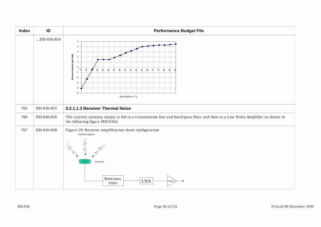
DD-036 Page 84 of 232 Printed 08 December 2000
Index
765
766
767
ID
…DD-036-854
DD-036-855
DD-036-856
DD-036-858
Performance Budget File
- 5
- 4
- 3
- 2
- 1
0
1
2
3
4
5
5 10 15 20 25 30 35 40 45 50 55 60 65 70 75 80 85 90
E l e v a t i o n ( ° )
Rec
eive
an
ten
na
gai
n (
dB
)
5.2.1.1.3 Receiver Thermal Noise
The receiver antenna output is fed to a transmission line and band-pass filter and then to a Low Noise Amplifier as shown inthe following figure [RD-016]:
Figure 29: Receiver amplification chain configuration
Band-pass Filter LNA
Antenna
Galileo signals
Ampli 1
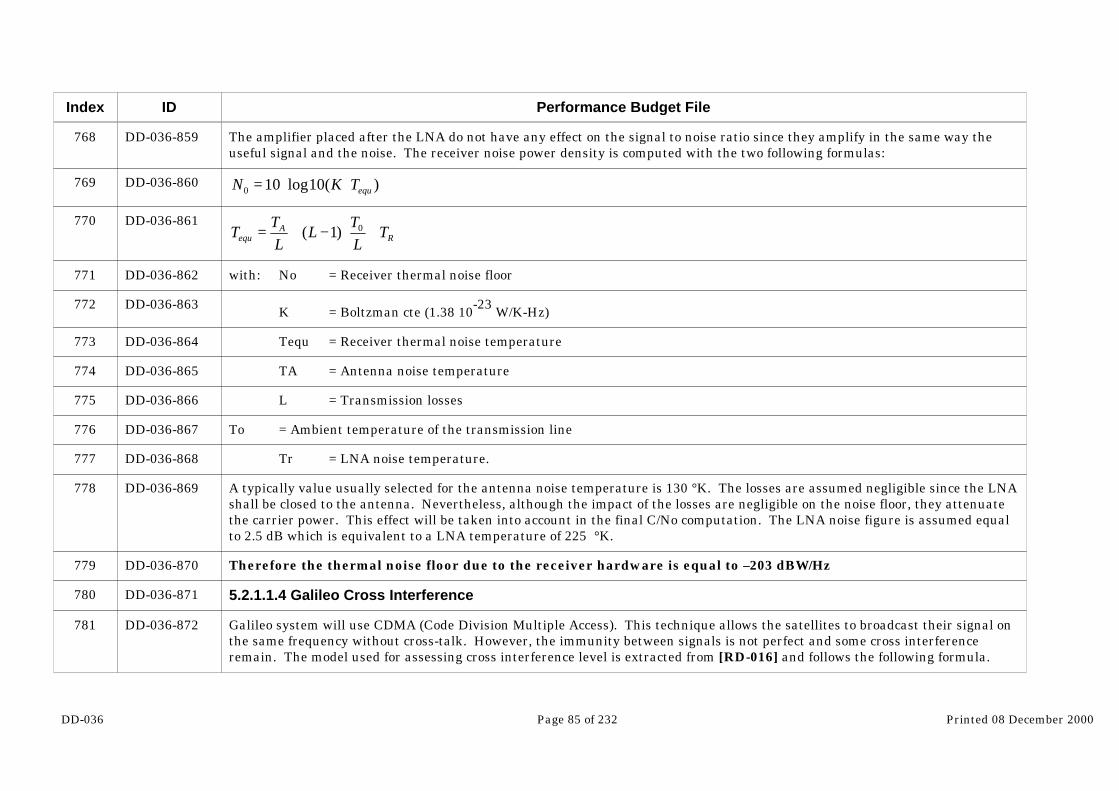
DD-036 Page 85 of 232 Printed 08 December 2000
Index
768
769
770
771
772
773
774
775
776
777
778
779
780
781
ID
DD-036-859
DD-036-860
DD-036-861
DD-036-862
DD-036-863
DD-036-864
DD-036-865
DD-036-866
DD-036-867
DD-036-868
DD-036-869
DD-036-870
DD-036-871
DD-036-872
Performance Budget File
The amplifier placed after the LNA do not have any effect on the signal to noise ratio since they amplify in the same way theuseful signal and the noise. The receiver noise power density is computed with the two following formulas:
)(10log100 equTKN ⋅⋅=
RA
equ TLT
LL
TT +⋅−+= 0)1(
with: No = Receiver thermal noise floor
K = Boltzman cte (1.38 10-23 W/K-Hz)
Tequ = Receiver thermal noise temperature
TA = Antenna noise temperature
L = Transmission losses
To = Ambient temperature of the transmission line
Tr = LNA noise temperature.
A typically value usually selected for the antenna noise temperature is 130 °K. The losses are assumed negligible since the LNAshall be closed to the antenna. Nevertheless, although the impact of the losses are negligible on the noise floor, they attenuatethe carrier power. This effect will be taken into account in the final C/No computation. The LNA noise figure is assumed equalto 2.5 dB which is equivalent to a LNA temperature of 225 °K.
Therefore the thermal noise floor due to the receiver hardware is equal to –203 dBW/Hz
5.2.1.1.4 Galileo Cross Interference
Galileo system will use CDMA (Code Division Multiple Access). This technique allows the satellites to broadcast their signal onthe same frequency without cross-talk. However, the immunity between signals is not perfect and some cross interferenceremain. The model used for assessing cross interference level is extracted from [RD-016] and follows the following formula.

DD-036 Page 86 of 232 Printed 08 December 2000
Index
782
783
784
785
786
787
788
792
793
ID
DD-036-873
DD-036-874
DD-036-875
DD-036-876
DD-036-877
DD-036-878
DD-036-901
DD-036-902
DD-036-903
Performance Budget File
( )c
scross f
PMN ⋅−⋅= 1
32
With Ncross = Noise component due to cross interference
M = Number of Galileo Satellite in sight
Ps = Power of one interfering signal at antenna output
fc = Chip rate
The main limitations of such a model is that the code is not ideal, and with quasi-stationary phenomena the impact could bestronger. It can be assumed however that the code is long enough to be considered as ideal. This will be refined after havingrefined the code length of the signal structure. The factor 2/3 is valid for square signal. In the case that the PRN is filtered aton lobe this parameter can raise up to 0.8. According to the baseline, the total satellite number in the constellation is 30. Therefore, the number of satellite in sight of one user is supposed not to exceed 15 satellites. According to Figure 27 themaximum power on ground with a 0 dBi antenna is -153.4 dBw. The satellites are considered spread on all the azimuth,therefore the power unbalance due to the antenna is selected at the mean gain which is 2.8 dB. However, cross interference aresubject to a 2 dB losses in the receiver. Therefore the noise power due to cross interference for each frequency is detailed in thefollowing table.
Table 6: Cross Interference Power
Carrier Max PowerLevel
Mean AntennaGain
Rx losses Chip rate Cross interferingpower
E1 -153.4 dBw +2.8 dB 2 dB 2.046 MHz -205 dBw/Hz
E5 -153.4 dBw +2.8 dB 2 dB 10.23 MHz -212 dBw/Hz
5.2.1.1.5 External Interference
The signal to noise ratio is also affected by external interference. This depends obviously of the characteristics of theelectromagnetic environment of the user. This environment is quite difficult to identify because it is different for all users.

DD-036 Page 87 of 232 Printed 08 December 2000
Index
794
795
796
797
798
799
800
801
802
803
804
ID
DD-036-904
DD-036-905
DD-036-906
DD-036-907
DD-036-908
DD-036-909
DD-036-910
DD-036-911
DD-036-912
DD-036-913
DD-036-914
Performance Budget File
For Galileo one main issue in terms of frequency band allocation is the presence of radar and DME in E6 and E5 bandwidth. However those radar are seen only from high altitudes. Typically, ground users and low altitude users will not suffer this kindof interference. Therefore in terms of performance we have two cases.
The user is at high altitude and is subject to interference. This degrades the performance, but since the performance requiredat this altitude is quite relax, the interference should not be significantly. The main objective will be to keep tracking thesignal. This is why a narrow band signal less subject to interference has been added on E5.
At low altitude, the user does not see the interference due to radar and DME. Therefore he can track the wide band signalwithout specific problems and get a better accuracy.
The strategy to account for external interference in the UERE budget will be to define a maximum level of interference underwhich the performance should be met. This level will play in GALA study the same role as the MOPS-RTCA mask for civilaviation users. The model used to assess the noise component due to interference is the following [RD-016]:
cI f
JN =
with: NI = Noise component due to external interference
J = Jammer Power at antenna output
fc = Chip rate
The main limitations of such a model is that the code is not ideal, and with quasi-stationarity phenomena the impact could bestronger. It can be assumed however that the code is long enough to be considered as ideal. This will be refined after havingrefined the code length of the signal structure.
The only application that has a clear baseline for interference is Civil Aviation. This baseline specifies the maximum level ofinterference under which the user segment may have to operate.
For tone interference the maximum interference level in band level is equal to –120 dBm. However this value assumes the useof a 1023 bits 1 MHz code. Galileo will use more robust signal structure. Therefore the external interference power will bespecified at the input of the loop which means that the jammer assumed will be different for each signal option.

DD-036 Page 88 of 232 Printed 08 December 2000
Index
805
806
810
811
812
816
817
ID
DD-036-915
DD-036-935
DD-036-936
DD-036-937
DD-036-957
DD-036-958
DD-036-960…
Performance Budget File
In the case of the current GPS signal structure with a jammer of –120 dBm with an antenna gain of 4.5 dB (worst case) , theexternal interfering power is computed at -205.6 dBw/Hz. This figure will be taken for all the signal structure.
Table 7: External Interference Power Level
Carrier Jammerpower
Mean AntennaGain
Chip rate External interferingpower
E1 -147 dBw +4.5 dB 2.046 MHz -205.6 dBw/Hz
E5 -134 dBw +4.5 dB 10.23 MHz -205.6 dBw/Hz
5.2.1.1.6 Signal to Noise Ratio
Taking into account the thermal noise, the noise due to cross-interference and the noise due to external interference, the globalnoise floor for each SAS frequency is equal to:
Table 8: Noise Floor
Carrier ThermalNoise
Cross interferencecomponent
External Interferencecomponent
Noise FloordBw/Hz
E1 -203 -205 -205.6 -199.6
E5 -203 -212 -205.6 -200.7
A budget of 2 dB is allocated to the receiver for the losses due to the sampler, feeder and correlator. This allows to derive thesignal to noise ratio for each carriers. The results are shown on the following graph:
Figure 30: C/No for E1 and E5

DD-036 Page 89 of 232 Printed 08 December 2000
Index
818
819
820
821
822
823
824
ID
…DD-036-960
DD-036-961
DD-036-962
DD-036-963
DD-036-964
DD-036-965
DD-036-966
DD-036-967
Performance Budget File
36
38
40
42
44
46
48
50
5 10 15 20 25 30 35 40 45 50 55 60 65 70 75 80 85 90
Elv angle
C/N
o in
dB
w/h
z
E1E5
5.2.1.2 Receiver Budget Error
5.2.1.2.1 Code Tracking Error
The tracking error depends of the kind of DLL used in the receiver. For a non coherent Delay Lock Loop, the tracking error atone sigma is equal to the following formula [RD-016]:
(m)
+⋅=
00
21
2 NCB
NCB
k FIccRx λσ
with: σRx : Tracking error at one sigma in meter
λc : Code wavelength

DD-036 Page 90 of 232 Printed 08 December 2000
Index
825
826
827
828
829
830
831
832
833
834
ID
DD-036-968
DD-036-969
DD-036-970
DD-036-971
DD-036-972
DD-036-973
DD-036-974
DD-036-975
DD-036-976
DD-036-978…
Performance Budget File
Bc : Code loop bandwidth
K : Factor taking into account the signal wave shape (=1 for a square signal can
reach 0.75 for a QPN signal
BFI : Pre-detection Bandwidth
C/No : Carrier to Noise Ratio including thermal noise, cross and external
interference
However, this formula is the Cramer-Rao bound of the pseudo-range accuracy; it means that such a value will be achieved only ifstatistical properties of signal and noise fit closely with the theoretical ones, and that the used estimator is the optimal one(according maximum likelihood approach). Therefore a margin of at least 50% needs to be integrated to take into accountreceiver technological discrepancies.
As specified in the chapter 5.1 the user is assumed dynamic. However, main of the receivers use PLL aiding to cope withdynamic. Therefore the loop bandwidth selected is the same that would have been selected for a static/low dynamic user, that isto say 2 Hz. The pre-detection bandwidth is directly linked to the symbol rate. The pre-detection bandwidth is thereforeselected at 330 Hz for E5 and 300 Hz for E1.
Considering those assumptions the tracking error due to thermal noise, cross-interference and external interference is shown onthe following graph:
Figure 31: Code Tracking Error on E1 and E5

DD-036 Page 91 of 232 Printed 08 December 2000
Index
835
836
837
838
839
840
841
ID
…DD-036-978
DD-036-979
DD-036-980
DD-036-981
DD-036-982
DD-036-983
DD-036-984
DD-036-985
Performance Budget File
0
0,5
1
1,5
2
2,5
3
5 10 15 20 25 30 35 40 45 50 55 60 65 70 75 80 85 90
Elv Angle
Err
or
at 1
sig
ma
in m
E1E5
Due to a chip rate 5 times higher, the range measurement on E5 is much better the one available on E1.
5.2.1.2.2 Multipath Budget Error
The tracking loop measurement error do not depend only from the signal to noise ratio. Reflections of the navigation signal onobstacles (buildings, water, air-plane wings) disturb the carrier loop tracking. This phenomena is called multipath. This kind oferror is very difficult to model since it very much environment dependant. The difference can be quite high according to the userapplication. Furthermore, the type of technique implemented in the user receiver to mitigate the multipath has also a greatimpact on the residual error. According to the king of multipath to deal with, narrow correlation and carrier smoothing canreduce the residual error.
The key parameter that drives the multipath error at user level are:
- The number of reflections
- The attenuation of the reflection comparing to the direct path
- The delay of the reflection comparing to the direct path

DD-036 Page 92 of 232 Printed 08 December 2000
Index
842
843
844
845
846
847
848
849
850
851
ID
DD-036-986
DD-036-987
DD-036-988
DD-036-989
DD-036-990
DD-036-991
DD-036-992
DD-036-993
DD-036-994
DD-036-996…
Performance Budget File
- The difference of frequency between the reflection and direct path
The objective of this chapter is to define a model that aims at representing a mean multipath error. Of course, since it is verymuch environment dependant, according to the application, the error might be much higher than the model prediction. However, considering the worst case in the UERE budget would be too conservative. The system shall not be designed takinginto account the worst cases users, otherwise, it would be totally oversized.
The model selected is the one used in EGNOS. The multipath error at 1 sigma varies according to the elevation angle accordingto the following formula:
( ))tan(
45
θσ
σ°
= mpmp
with: σmp = Multipath budget error at 45 degrees
= Elevation Angle
For the EGNOS 3B service level the budget at 45 degrees for GPS is selected at 0.25 m. GPS signals have a chip rate of 1.023Mchips/s. Since Galileo signals have different chip rates and multipath error is strongly dependant of the chip rate, as a rule ofthumb, the multipath budget for Galileo will be linearly sized according to the chip rate. However, it has to be pointed out thatthis budget is achieved in EGNOS by using 30s integration time carrier smoothing to mitigate the multipath. EGNOS is asystem designed for civil aviation. Since the reference scenario for SAS/GAS is a landing aircraft, it makes sense to keep thesame assumptions in terms of integration time.
Taking account those assumptions, the multipath UERE budget after carrier smoothing for SAS/GAS is shown on thefollowing graph:
Figure 32: Multipath Error budget for E1 and E5
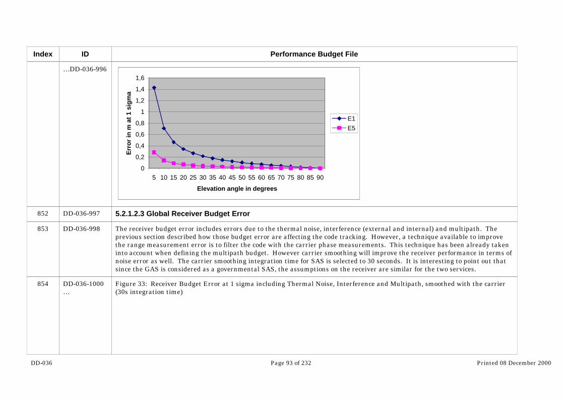
DD-036 Page 93 of 232 Printed 08 December 2000
Index
852
853
854
ID
…DD-036-996
DD-036-997
DD-036-998
DD-036-1000…
Performance Budget File
0
0,2
0,4
0,6
0,8
1
1,2
1,4
1,6
5 10 15 20 25 30 35 40 45 50 55 60 65 70 75 80 85 90
Elevation angle in degrees
Err
or
in m
at
1 si
gm
a
E1E5
5.2.1.2.3 Global Receiver Budget Error
The receiver budget error includes errors due to the thermal noise, interference (external and internal) and multipath. Theprevious section described how those budget error are affecting the code tracking. However, a technique available to improvethe range measurement error is to filter the code with the carrier phase measurements. This technique has been already takeninto account when defining the multipath budget. However carrier smoothing will improve the receiver performance in terms ofnoise error as well. The carrier smoothing integration time for SAS is selected to 30 seconds. It is interesting to point out thatsince the GAS is considered as a governmental SAS, the assumptions on the receiver are similar for the two services.
Figure 33: Receiver Budget Error at 1 sigma including Thermal Noise, Interference and Multipath, smoothed with the carrier(30s integration time)
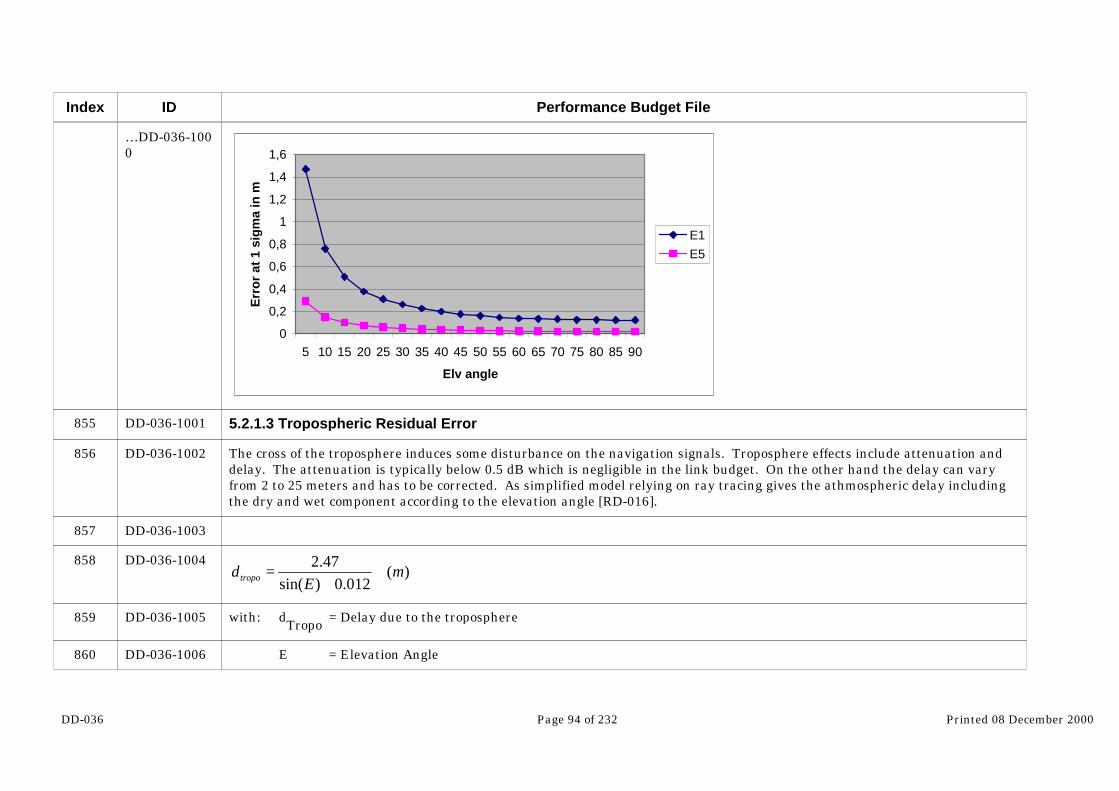
DD-036 Page 94 of 232 Printed 08 December 2000
Index
855
856
857
858
859
860
ID
…DD-036-1000
DD-036-1001
DD-036-1002
DD-036-1003
DD-036-1004
DD-036-1005
DD-036-1006
Performance Budget File
0
0,2
0,4
0,6
0,8
1
1,2
1,4
1,6
5 10 15 20 25 30 35 40 45 50 55 60 65 70 75 80 85 90
Elv angle
Err
or
at 1
sig
ma
in m
E1E5
5.2.1.3 Tropospheric Residual Error
The cross of the troposphere induces some disturbance on the navigation signals. Troposphere effects include attenuation anddelay. The attenuation is typically below 0.5 dB which is negligible in the link budget. On the other hand the delay can varyfrom 2 to 25 meters and has to be corrected. As simplified model relying on ray tracing gives the athmospheric delay includingthe dry and wet component according to the elevation angle [RD-016].
)(012.0)sin(
47.2m
Ed tropo +
=
with: dTropo = Delay due to the troposphere
E = Elevation Angle

DD-036 Page 95 of 232 Printed 08 December 2000
Index
861
862
863
864
865
ID
DD-036-1007
DD-036-1008
DD-036-1009
DD-036-1011
DD-036-1012
Performance Budget File
The dry component which represents 90% of the total delay is something quite easy to predict. This not the case for the wetcomponent. In order to compensate the wet component measures of temperature and humidity are necessary. In ComparativeSystem Study, the accuracy of this model was assumed equal to 4% of the tropospheric delay. However this assumes that thedry component is removed and external sensors are used to correct half of the wet component delay. This will induce complexity(interface, extra sensor, additional software) and cost at receiver and cannot be taken for granted without further trade-off.Therefore the accuracy of the model is estimated at 10% and the residual tropospheric error at one sigma is equal to:
)(1.0*012.0)sin(
47.2m
Etropo +=σ
with: σTropo = Residual error due to the troposphere at 1 sigma
Figure 34: Residual error due to the troposphere at 1 sigma
0
0,5
1
1,5
2
2,5
3
5 10 15 20 25 30 35 40 45 50 55 60 65 70 75 80 85 90
Elv Angle in degree
Err
or
at 1
sig
ma
in m
The tropospheric delay is also quite dependant from the temperature, pressure and humidity as explained in the RTCA-MOPS[RD-014]. Nevertheless the correction accuracy are quite independent of those phenomena and the tropospheric error accordingto the elevation angle showed above is quite close to the one detailed in the MOPS for all conditions.

DD-036 Page 96 of 232 Printed 08 December 2000
Index
866
867
868
869
870
871
872
873
874
875
876
877
878
ID
DD-036-1013
DD-036-1014
DD-036-1015
DD-036-1016
DD-036-1017
DD-036-1018
DD-036-1019
DD-036-1020
DD-036-1021
DD-036-1022
DD-036-1023
DD-036-1024
DD-036-1025
Performance Budget File
5.2.1.4 Total UERE after Dual Frequency Processing
When two signals are emitted by the satellite on two different carriers, it is possible to remove the error due to ionosphere bycombining measurements from the two carriers. The ionospheric delay on the first carrier can be expressed with the followingformula:
22
21
22
212
1
ffff
ionofree −−
=ρρ
ρ
With ρ1 = Pseudorange on carrier 1.
ρ2 = Pseudorange on carrier 2.
ρionofree = Pseudorange after ionopheric correction.
f1 = Frequency of carrier 1
f2 = frequency of carrier 2
The standard deviation of the ionospheric delay estimator is equal to:
( )222
21
22
42
21
41
ff
ffionofree
−
+=
σσσ
With σ1 = Standard deviation of ρ1 measurement
σ2 = Standard deviation of ρ2 measurement
The tropospheric error on each frequency are assumed correlated. Therefore it is not amplified by the processing of themeasurement on both frequency for correction of the ionospheric delay.

DD-036 Page 97 of 232 Printed 08 December 2000
Index
879
880
881
882
883
884
885
886
887
888
ID
DD-036-1026
DD-036-1027
DD-036-1028
DD-036-1029
DD-036-1030
DD-036-1031
DD-036-1032
DD-036-1033
DD-036-1034
DD-036-1036…
Performance Budget File
The clock and ephemeris error is also not frequency dependant. Therefore it is not altered by the dual frequency processing. The budget for clock and Ephemeris error is equal to 0.65 m at 1 sigma.
Therefore the pseudorange error at one sigma is equal to:
( ) ectropoRxRx
psdff
ff+++
−
+= 22
222
21
22
42
21
41 σσ
σσσ
With σ1 = Rx budget Error on Carrier 1
σ2 = Rx budget Error on Carrier 2
σtropo = Tropospheric budget error
σc+e = Clock and Ephemeris Budget Error
5.2.1.4.1 UERE with high multipath
The total UERE for SAS service taking into account pessimistic assumptions for multipath is detailed on the following graph and table:
Figure 35: Total UERE with high multipath

DD-036 Page 98 of 232 Printed 08 December 2000
Index
889
ID
…DD-036-1036
DD-036-1163
Performance Budget File
00.5
11.5
22.5
33.5
44.5
5
5 15 25 35 45 55 65 75 85
Elevation Angle
Err
or
at 1
sig
ma
in m
tropo
Tot Rx
clock+ephem
Tot UERE
Tot UERE+10%
Table 9: UERE with high multipath
Elv Receiver Tot Rx Tropo Clock+Eph
Total Total+10%margin
E1 E5 (Dual freq)
5 1,47 0,29 3,45 2,49 0,65 4,31 4,74
10 0,76 0,15 1,78 1,33 0,65 2,31 2,55
15 0,51 0,10 1,20 0,91 0,65 1,64 1,81
20 0,38 0,07 0,89 0,70 0,65 1,31 1,44
25 0,31 0,06 0,73 0,57 0,65 1,13 1,24
30 0,26 0,05 0,62 0,48 0,65 1,02 1,12
40 0,20 0,03 0,47 0,38 0,65 0,88 0,97
50 0,16 0,03 0,38 0,32 0,65 0,82 0,90
60 0,14 0,02 0,32 0,28 0,65 0,78 0,86

DD-036 Page 99 of 232 Printed 08 December 2000
Index
904
905
906
907
ID
DD-036-1164
DD-036-1165
DD-036-1167
DD-036-1295
Performance Budget File
70 0,13 0,02 0,31 0,26 0,65 0,76 0,84
80 0,13 0,02 0,30 0,25 0,65 0,76 0,83
90 0,12 0,02 0,29 0,24 0,65 0,75 0,83
5.2.1.4.2 UERE with low multipath
In low multipath environment, the impact of multipath on the error budget is considered as negligible comparing to the othercomponents:
Figure 36: Total UERE with low multipath
0,00
0,50
1,00
1,50
2,00
2,50
3,00
3,50
5 15 25 35 45 55 65 75 85
Elevation Angle in m
Err
or
at 1
sig
ma
in m
RxTropoClock+EphemTotalTot+10%
Table 10: UERE with low multipath
Elv Receiver Tot Rx Tropo Clock budget TOTAL
Total+10%
E1 E5
5 0,34 0,06 0,81 2,49 0,65 2,70 2,97
10 0,27 0,05 0,63 1,33 0,65 1,61 1,77

DD-036 Page 100 of 232 Printed 08 December 2000
Index
922
923
924
925
926
927
ID
DD-036-1296
DD-036-1297
DD-036-1298
DD-036-1299
DD-036-1300
DD-036-1301
Performance Budget File
15 0,21 0,04 0,49 0,91 0,65 1,22 1,35
20 0,16 0,03 0,38 0,70 0,65 1,03 1,13
25 0,16 0,03 0,36 0,57 0,65 0,94 1,03
30 0,15 0,03 0,35 0,48 0,65 0,88 0,97
40 0,13 0,02 0,31 0,38 0,65 0,81 0,89
50 0,12 0,02 0,29 0,32 0,65 0,78 0,86
60 0,12 0,02 0,28 0,28 0,65 0,76 0,84
70 0,12 0,02 0,29 0,26 0,65 0,76 0,83
80 0,12 0,02 0,29 0,25 0,65 0,75 0,83
90 0,12 0,02 0,29 0,24 0,65 0,75 0,83
5.3 Dual L band frequency UERE with OAS/CAS1 receiver assumption
5.3.1 UERE budget error in GLOBAL
The detail UERE computation are available in ANNEX C. Only the relevant difference comparing to the previous scenario aredescribe in this chapter.
One main difference is the difference of the integration time used for carrier smoothing. For SAS/GAS the user is assumedbeing in the open and can afford to filter the signal during a 30s period. However, since the CAS1 (OAS) user is assumedmoving within the urban environment, the time will most likely not be able to filter on a long period. Therefore the filteringtime is reduced down to 6 seconds.
5.3.1.1 Multipath Budget Error
The OAS/CAS1 user is assumed moving in urban environment. However, since no model is available to model this kind of error,the strategy for CAS1 will be to use the same empirical model as used for SAS to define a requirement for multipath budgeterror. The model aims at representing a mean multipath error. Of course, since it is very much environment dependant,according to the application, the error might be much higher than the model prediction. However, considering the worst case inthe UERE budget would be too conservative. The system shall not be designed taking into account the worst cases users,otherwise, it would be totally oversized.

DD-036 Page 101 of 232 Printed 08 December 2000
Index
928
929
930
931
932
933
934
935
936
ID
DD-036-1302
DD-036-1303
DD-036-1304
DD-036-1305
DD-036-1306
DD-036-1307
DD-036-1308
DD-036-1309
DD-036-1311…
Performance Budget File
The empirical model selected is the one used in EGNOS. The multipath error at 1 sigma varies according to the elevation angleaccording to the following formula:
( ))tan(
45
θ
σσ
°= mp
mp
with: σmp = Multipath budget error at 45 degrees
= Elevation Angle
For the EGNOS 3B service level the budget at 45 degrees for GPS is selected at 0.25 m. GPS signals have a chip rate of 1.023Mchips/s. Since Galileo signals have different chip rates and multipath error is strongly dependant of the chip rate, as a rule ofthumb, the multipath budget for Galileo will be linearly sized according to the chip rate. However, it has to be pointed out thatthis budget is in EGNOS by using 30s integration time carrier smoothing to mitigate the multipath. This time may beaffordable for users in a open environment without obstacle such as civil aviation users. However for users moving in a urbanenvironment this time seems to long. Therefore, a more realistic integration time of 6 seconds is selected. Therefore, in orderto compensate for the 30s carrier smoothing, the multipath budget is multiplied by Sqrt(5).
Taking account those assumptions, the multipath UERE budget after carrier smoothing for OAS/CAS1 is shown on thefollowing graph:
Figure 37: Multipath Error budget E2 and E6

DD-036 Page 102 of 232 Printed 08 December 2000
Index
937
938
939
940
ID
…DD-036-1311
DD-036-1312
DD-036-1313
DD-036-1314
DD-036-1316…
Performance Budget File
0
0,5
1
1,5
2
2,5
3
3,5
5 10 15 20 25 30 35 40 45 50 55 60 65 70 75 80 85 90
Elevation Angle
Err
or
at 1
sig
ma
in m
E2E6
5.3.1.2 Total UERE after Dual Frequency Processing
The total UERE is detailed on the following graph and table:
5.3.1.2.1 Total UERE with high multipath
Figure 38: UERE with high multipat

DD-036 Page 103 of 232 Printed 08 December 2000
Index
941
ID
…DD-036-1316
DD-036-1443
Performance Budget File
0
2
4
6
8
10
12
5 15 25 35 45 55 65 75 85
Elevation Angle
Err
or
at 1
sig
ma
in m
TropoRxClock+EphemTotalTot+10%
Table 11: Dual Frequency UERE with high multipath
Elv Rx budget Rx Total Budget Tropo Clock budget TOTAL
Total + 10%margin
E2 E6 (Dual frequency)
5 3,30 0,33 10,06 2,49 0,65 10,39 11,43
10 1,71 0,17 5,22 1,33 0,65 5,43 5,97
15 1,16 0,11 3,54 0,91 0,65 3,72 4,09
20 0,86 0,08 2,63 0,70 0,65 2,80 3,08
25 0,71 0,07 2,16 0,57 0,65 2,33 2,56
30 0,61 0,06 1,85 0,48 0,65 2,02 2,22
40 0,46 0,04 1,41 0,38 0,65 1,60 1,76
50 0,38 0,04 1,16 0,32 0,65 1,37 1,50
60 0,33 0,03 1,01 0,28 0,65 1,23 1,36

DD-036 Page 104 of 232 Printed 08 December 2000
Index
956
957
972
ID
DD-036-1444
DD-036-1571
DD-036-1573…
Performance Budget File
70 0,32 0,03 0,96 0,26 0,65 1,19 1,31
80 0,31 0,03 0,94 0,25 0,65 1,17 1,29
90 0,30 0,03 0,92 0,24 0,65 1,15 1,27
5.3.1.2.2 Total UERE with low multipath
Table 12: UERE budget with low multipath
Elv Rx budget Tot Rx Tropo Clock+Eph
Total Total+10%margin
E2 E6 Dual frequ
5 0,77 0,08 2,34 2,49 0,65 3,48 3,83
10 0,60 0,06 1,82 1,33 0,65 2,34 2,58
15 0,47 0,04 1,43 0,91 0,65 1,82 2,00
20 0,36 0,03 1,10 0,70 0,65 1,46 1,60
25 0,35 0,03 1,06 0,57 0,65 1,36 1,50
30 0,33 0,03 1,01 0,48 0,65 1,30 1,43
40 0,30 0,03 0,90 0,38 0,65 1,17 1,29
50 0,27 0,02 0,84 0,32 0,65 1,11 1,22
60 0,26 0,02 0,80 0,28 0,65 1,07 1,18
70 0,27 0,02 0,83 0,26 0,65 1,09 1,20
80 0,28 0,02 0,85 0,25 0,65 1,10 1,21
90 0,28 0,02 0,84 0,24 0,65 1,09 1,20
Figure 39: UERE with low multipath

DD-036 Page 105 of 232 Printed 08 December 2000
Index
973
974
975
976
977
978
979
980
ID
…DD-036-1573
DD-036-1574
DD-036-1577
DD-036-1578
DD-036-1579
DD-036-1580
DD-036-1581
DD-036-1582
DD-036-1583
Performance Budget File
0
0,5
1
1,5
2
2,5
3
3,5
4
4,5
5 15 25 35 45 55 65 75 85
Elv angle in degrees
Err
or
in m
at
1 si
gm
a
TropoRxClock+EphemTotalTotal+10%
5.4 Single L band frequency UERE with OAS/CAS1 receiver assumptions
5.4.1 Residual Ionospheric Error
The ionospheric delay depends from the TEC (Total Electron Content) and the frequency of the carrier according the followingformula:
)()(*3.40
2 mEFf
TECdiono ×=
with: diono
= Ionospheric delay in m
TEC = Total Electron Content
F(.) = Obliquity factor [RD-016]
f = Carrier frequency
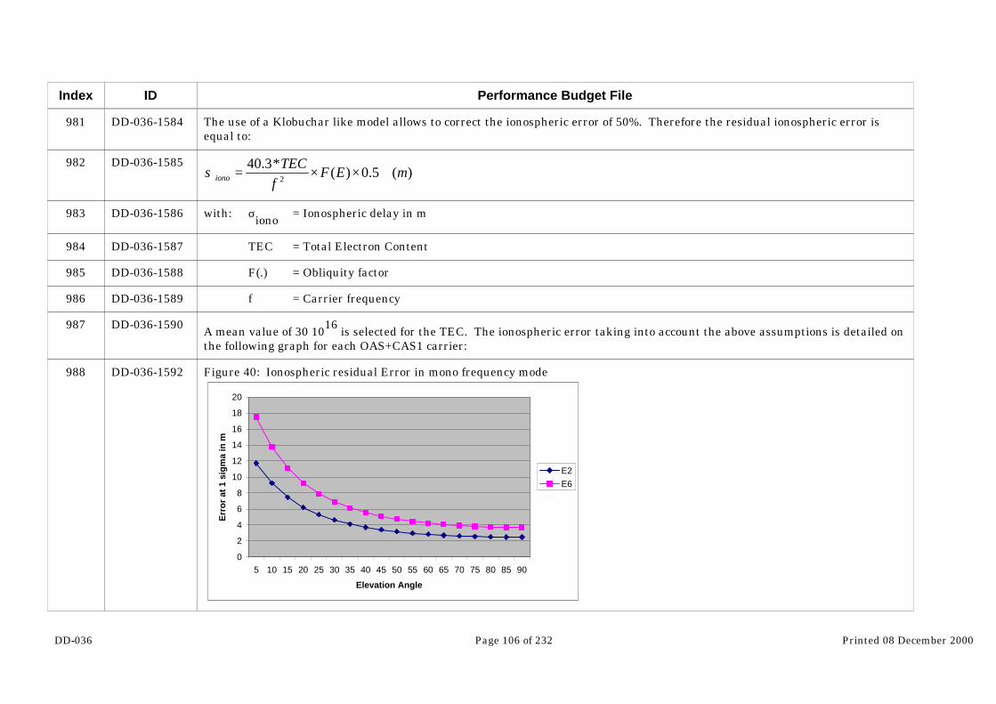
DD-036 Page 106 of 232 Printed 08 December 2000
Index
981
982
983
984
985
986
987
988
ID
DD-036-1584
DD-036-1585
DD-036-1586
DD-036-1587
DD-036-1588
DD-036-1589
DD-036-1590
DD-036-1592
Performance Budget File
The use of a Klobuchar like model allows to correct the ionospheric error of 50%. Therefore the residual ionospheric error isequal to:
)(5.0)(*3.40
2 mEFf
TECiono ××=σ
with: σiono = Ionospheric delay in m
TEC = Total Electron Content
F(.) = Obliquity factor
f = Carrier frequency
A mean value of 30 1016 is selected for the TEC. The ionospheric error taking into account the above assumptions is detailed onthe following graph for each OAS+CAS1 carrier:
Figure 40: Ionospheric residual Error in mono frequency mode
0
2
4
6
8
10
12
14
16
18
20
5 10 15 20 25 30 35 40 45 50 55 60 65 70 75 80 85 90
Elevation Angle
Err
or
at 1
sig
ma
in m
E2E6

DD-036 Page 107 of 232 Printed 08 December 2000
Index
989
990
991
992
993
994
995
ID
DD-036-1593
DD-036-1594
DD-036-1595
DD-036-1596
DD-036-1597
DD-036-1599
DD-036-1713
Performance Budget File
5.4.2 Total UERE
The carrier selected for the single frequency service is E2. This choice is done for two reasons:
The chip rate is lower than on E6, therefore the receiver will be simpler and cheaper
Although the error due to the receiver is higher on this frequency comparing to E6, the UERE is much better thanks to aionospheric residual error lower.
The following graph shows the UERE for a mono frequency service:
Figure 41: UERE for E2 single frequency service
0
2
4
6
8
10
12
14
16
5 15 25 35 45 55 65 75 85
Elevation Angle
Err
or
at 1
sig
ma
in m
Tot UERETot+10%
Table 13: Single frequency service UERE
ElevationAngle
Rx budget Tropo Clockbudget
iono Total Total+10%margin

DD-036 Page 108 of 232 Printed 08 December 2000
Index
1010
1011
1012
1013
1014
1015
ID
DD-036-1714
DD-036-1715
DD-036-1716
DD-036-1717
DD-036-1718
DD-036-1719
Performance Budget File
5 3,30 2,49 0,65 11,74 12,47 13,71
10 1,71 1,33 0,65 9,24 9,51 10,46
15 1,16 0,91 0,65 7,47 7,64 8,40
20 0,86 0,70 0,65 6,21 6,34 6,97
25 0,71 0,57 0,65 5,30 5,41 5,95
30 0,61 0,48 0,65 4,62 4,73 5,21
40 0,46 0,38 0,65 3,73 3,83 4,21
50 0,38 0,32 0,65 3,18 3,28 3,61
60 0,33 0,28 0,65 2,84 2,95 3,24
70 0,32 0,26 0,65 2,63 2,74 3,01
80 0,31 0,25 0,65 2,52 2,63 2,89
90 0,30 0,24 0,65 2,48 2,59 2,85
5.5 Single C band frequency UERE with SAS/GAS receiver assumptions
The assumptions to compute the UERE budgets are mainly the same than for SAS/GAS dual frequency service. The detailUERE computation are available in ANNEX C. Only the relevant difference are described in this chapter.
One main difference is the difference of the integration time used for carrier smoothing. For SAS/GAS L band dual frequencyservice the user is assumed being in the open and can afford to filter the signal during a 30s period. For C band, since the noiseis not amplified with dual frequency processing, 10 seconds integration time appear enough to reach the same performance.
5.5.1 UERE in Global
5.5.1.1 Multipath Budget Error
Multipath error for has been computed using the same assumptions used for the other services. The following graph shows themultipath budget at 1 sigma after filtering. However in that case the integration time of carrier smoothing is selected to 10seconds. In order to compensate the fact that carrier smoothing filtering time is 10s instead of 30s, the budget in amplified of afactor 1.7 (sqrt(3)).

DD-036 Page 109 of 232 Printed 08 December 2000
Index
1016
1017
1018
1019
1020
ID
DD-036-1721
DD-036-1722
DD-036-1723
DD-036-1724
DD-036-1726…
Performance Budget File
Figure 42: Multipath Error
0
0,1
0,2
0,3
0,4
0,5
0,6
0,7
5 10 15 20 25 30 35 40 45 50 55 60 65 70 75 80 85 90
Elevation Angle
Err
or
at 1
sig
ma
in m
5.5.1.2 Ionospheric Budget Error
This service includes only one frequency on C band. Therefore, no dual frequency processing is possible to get rid of the delaydue to the ionosphere. However, since the ionospheric error at C band is very much reduced compared to L band twofrequencies are not indispensable. Nevertheless, as for L band mono frequency mode, a model of the ionosphere could be used toreduce the error due to ionosphere. However since the efficiency of this kind of model is very poor in C band comparing to Lband (10% improvement in C band comparing to 50% in L band) and since the ionopheric error is no longer a driver in the totalbudget error, no ionospheric model will be used.
The ionospheric error taking into account the same assumptions used for L band is detailed on the following graph:
Figure 43: Residual Ionospheric Error
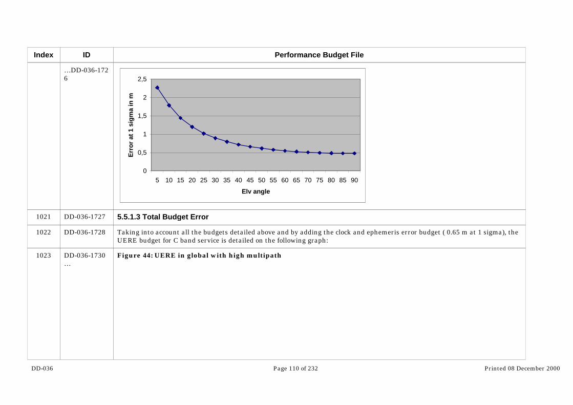
DD-036 Page 110 of 232 Printed 08 December 2000
Index
1021
1022
1023
ID
…DD-036-1726
DD-036-1727
DD-036-1728
DD-036-1730…
Performance Budget File
0
0,5
1
1,5
2
2,5
5 10 15 20 25 30 35 40 45 50 55 60 65 70 75 80 85 90
Elv angle
Err
or
at 1
sig
ma
in m
5.5.1.3 Total Budget Error
Taking into account all the budgets detailed above and by adding the clock and ephemeris error budget ( 0.65 m at 1 sigma), theUERE budget for C band service is detailed on the following graph:
Figure 44: UERE in global with high multipath
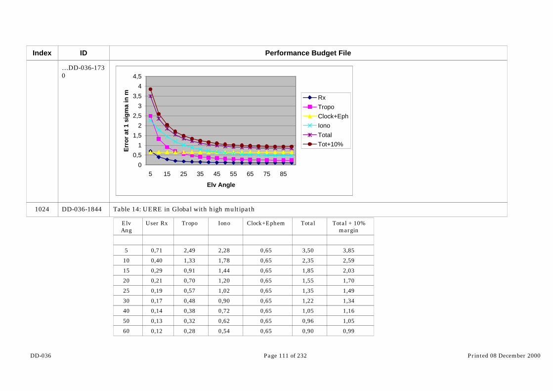
DD-036 Page 111 of 232 Printed 08 December 2000
Index
1024
ID
…DD-036-1730
DD-036-1844
Performance Budget File
0
0,5
1
1,5
2
2,5
3
3,5
4
4,5
5 15 25 35 45 55 65 75 85
Elv Angle
Err
or
at 1
sig
ma
in m Rx
TropoClock+EphIonoTotalTot+10%
Table 14: UERE in Global with high multipath
ElvAng
User Rx Tropo Iono Clock+Ephem Total Total + 10%margin
5 0,71 2,49 2,28 0,65 3,50 3,85
10 0,40 1,33 1,78 0,65 2,35 2,59
15 0,29 0,91 1,44 0,65 1,85 2,03
20 0,21 0,70 1,20 0,65 1,55 1,70
25 0,19 0,57 1,02 0,65 1,35 1,49
30 0,17 0,48 0,90 0,65 1,22 1,34
40 0,14 0,38 0,72 0,65 1,05 1,16
50 0,13 0,32 0,62 0,65 0,96 1,05
60 0,12 0,28 0,54 0,65 0,90 0,99

DD-036 Page 112 of 232 Printed 08 December 2000
Index
1039
1040
1041
1042
1043
1044
1045
1046
1047
1048
1049
ID
DD-036-1845
DD-036-1846
DD-036-1847
DD-036-1848
DD-036-1849
DD-036-1850
DD-036-1851
DD-036-1852
DD-036-1853
DD-036-1854
DD-036-1855
Performance Budget File
70 0,12 0,26 0,50 0,65 0,87 0,96
80 0,12 0,25 0,48 0,65 0,86 0,94
90 0,12 0,24 0,48 0,65 0,85 0,94
Since the service is single frequency, multipath does not have a great impact on the final UERE budget. Therefore the budgetswith and without multipath are similar.
5.6 UERE in Local
5.6.1 L band UERE budget with SAS/GAS receiver assumptions
5.6.1.1 Receiver Budget Error
5.6.1.1.1 Code measurements
In local only one frequency is used. Therefore the receiver budget error is the one that has been computed for E5 in global. Inlocal the fact to use only one frequency allows to take fully advantage of the high chip rate present on E5 (10.23 MHz). InGlobal it was not the case since, because of the dual frequency processing, all the noise was mainly due to E1 that had a chiprate much lower (2.046 MHz).
However, it is also necessary to take into account the budget error of the receiver placed in the local station. The only differencecomparing to the user receiver comes from the multipath. The user receiver error for SAS/GAS in local has been computedusing the same assumptions used for SAS/GAS in global.
For the reference station receiver error, the assumptions are mainly identical to the ones made for the user except for themultipath budget. Indeed, since the reference receiver is not moving, it is not possible to filter out the error due to multipath. That is why in EGNOS 3A, the multipath budget for the reference station (RIMS) is different from the one used for the usersegment. The model in inverse tangent is still applicable , however the value for GPS is increased from 0.25 to 0.5 meters. ForGalileo SAS, the multipath at 45 degrees after filtering for the reference receiver is:
σmp=0.25 m for E1 (2.046 Mc/s)
σmp=0.05 m for E5 (10.23 Mc/s)
5.6.1.2 Troposphere Budget Error

DD-036 Page 113 of 232 Printed 08 December 2000
Index
1050
1051
1052
1053
1054
1055
1056
ID
DD-036-1856
DD-036-1857
DD-036-1858
DD-036-1859
DD-036-1860
DD-036-1861
DD-036-1862
Performance Budget File
In local the delay due to the troposphere is corrected using the information broadcast by the reference station. The accuracy ofthis correction depends of the distance between the user and the station. The dependency between this distance and thetropospheric residual error is assumed with the following model:
RVtropo ∆⋅⋅= −6102σ
With: σVtropo= Vertical tropospheric residual Error at 1 sigma (m)
∆R = Distance between the station and the user in m.
This residual error depends from the distance between the station and the receiver but also from the elevation angle. Thisdependance is expressed with the following formula :
)sin(EVtropo
Tropo
σσ =
For a baseline of 10 km between the station and the user the vertical tropospheric residual error is equal to 0.02 m. Theresidual tropospheric error in local is detailed in the following graph :

DD-036 Page 114 of 232 Printed 08 December 2000
Index
1057
1058
1059
1060
1061
1062
1063
ID
DD-036-1864
DD-036-1865
DD-036-1866
DD-036-1867
DD-036-1868
DD-036-1869
DD-036-1870
Performance Budget File
Figure 45: Tropospheric error in local
0
0,05
0,1
0,15
0,2
0,25
5 10 15 20 25 30 35 40 45 50 55 60 65 70 75 80 85 90
Elevation Angle
Err
or
in m
at
1 si
gm
aTropo
5.6.1.3 Ionosphere Budget Error
In local the delay due to the ionosphere is also corrected using the information broadcast by the reference station. The accuracyof this correction depends of the distance between the user and the station. The dependency between this distance and theionosphere residual error is similar to the one used for the ionosphere (extracted from [RD-016]):
RViono ∆⋅⋅= −6102σ
With: σiono = Vertical Ionosphere residual Error at 1 sigma (m)
∆R = Distance between the station and the user in km.
This residual error depends also from the elevation angle though the obliquity factor. For a baseline of 10 km between thestation and the user the ionosphere residual error is equal to 0.02 m.
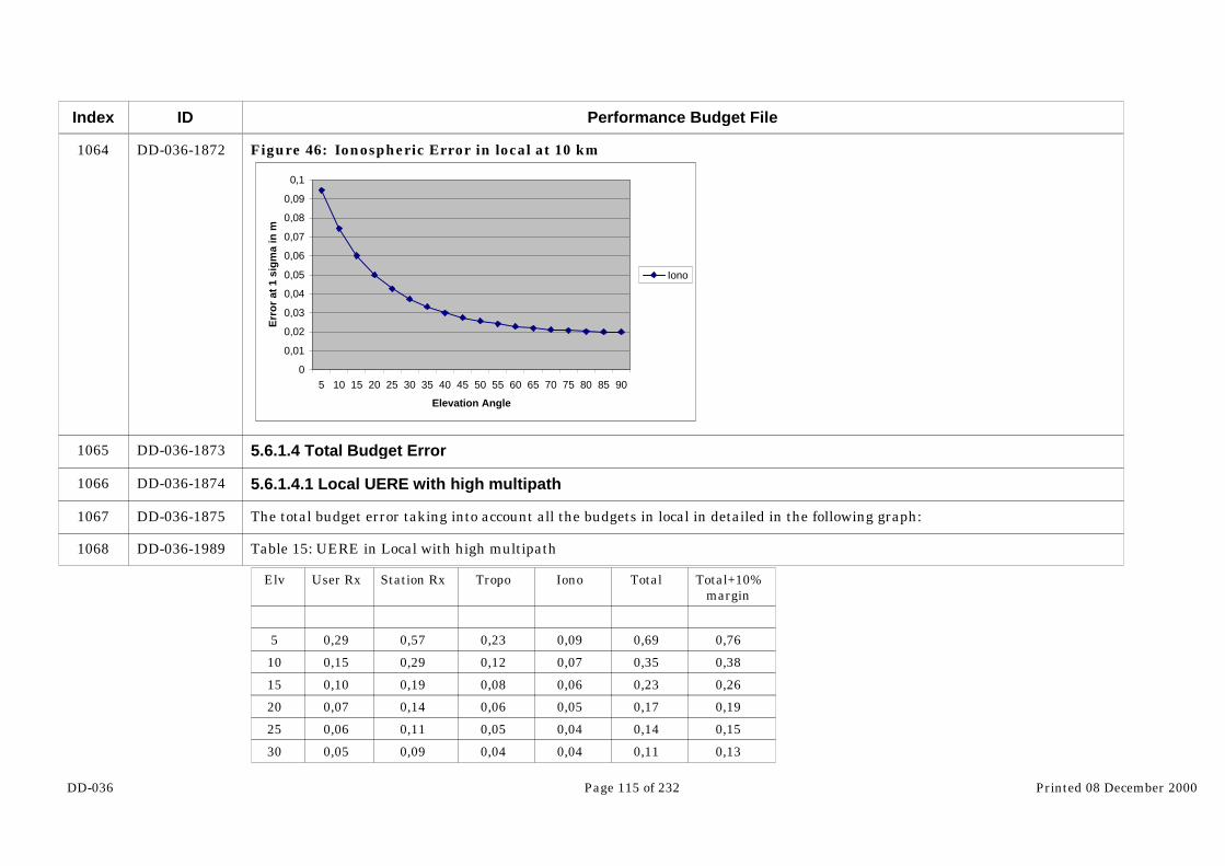
DD-036 Page 115 of 232 Printed 08 December 2000
Index
1064
1065
1066
1067
1068
ID
DD-036-1872
DD-036-1873
DD-036-1874
DD-036-1875
DD-036-1989
Performance Budget File
Figure 46: Ionospheric Error in local at 10 km
0
0,01
0,02
0,03
0,04
0,05
0,06
0,07
0,08
0,09
0,1
5 10 15 20 25 30 35 40 45 50 55 60 65 70 75 80 85 90
Elevation Angle
Err
or
at 1
sig
ma
in m
Iono
5.6.1.4 Total Budget Error
5.6.1.4.1 Local UERE with high multipath
The total budget error taking into account all the budgets in local in detailed in the following graph:
Table 15: UERE in Local with high multipath
Elv User Rx Station Rx Tropo Iono Total Total+10%margin
5 0,29 0,57 0,23 0,09 0,69 0,76
10 0,15 0,29 0,12 0,07 0,35 0,38
15 0,10 0,19 0,08 0,06 0,23 0,26
20 0,07 0,14 0,06 0,05 0,17 0,19
25 0,06 0,11 0,05 0,04 0,14 0,15
30 0,05 0,09 0,04 0,04 0,11 0,13

DD-036 Page 116 of 232 Printed 08 December 2000
Index
1083
1084
1085
ID
DD-036-1991
DD-036-1992
DD-036-2106
Performance Budget File
40 0,03 0,06 0,03 0,03 0,08 0,09
50 0,03 0,04 0,03 0,03 0,06 0,07
60 0,02 0,03 0,02 0,02 0,05 0,06
70 0,02 0,02 0,02 0,02 0,04 0,05
80 0,02 0,02 0,02 0,02 0,04 0,04
90 0,02 0,02 0,02 0,02 0,04 0,04
Figure 47: UERE in local with high multipath
0
0,1
0,2
0,3
0,4
0,5
0,6
0,7
0,8
5 15 25 35 45 55 65 75 85
Elevation Angle
Err
or
at 1
sig
ma
in m
User RxStat RxTot RxTotal UERETot UERE +10%
5.6.1.4.2 Local UERE with low multipath
Table 16: UERE in Local with low multipath
Elv Rx Station User Rx Tropo Iono Total Total+10%
5 0,06 0,06 0,23 0,09 0,26 0,29

DD-036 Page 117 of 232 Printed 08 December 2000
Index
1100
1101
ID
DD-036-2108
DD-036-2109
Performance Budget File
10 0,05 0,05 0,12 0,07 0,15 0,17
15 0,04 0,04 0,08 0,06 0,11 0,12
20 0,03 0,03 0,06 0,05 0,09 0,10
25 0,03 0,03 0,05 0,04 0,07 0,08
30 0,03 0,02 0,04 0,04 0,07 0,07
40 0,02 0,02 0,03 0,03 0,05 0,06
50 0,02 0,02 0,03 0,03 0,05 0,05
60 0,02 0,02 0,02 0,02 0,04 0,05
70 0,02 0,02 0,02 0,02 0,04 0,05
80 0,02 0,02 0,02 0,02 0,04 0,05
90 0,02 0,02 0,02 0,02 0,04 0,05
Figure 48: UERE with low multipath
0,00
0,05
0,10
0,15
0,20
0,25
0,30
0,35
5 10 15 20 25 30 40 50 60 70 80 90
Elv angle in degree
Err
or
at 1
sig
ma
in m Rx station
Rx UserTropoIonoTotalTot+10%
5.6.2 L band UERE budget with OAS/CAS1 receiver assumptions

DD-036 Page 118 of 232 Printed 08 December 2000
Index
1102
1103
1104
1105
ID
DD-036-2110
DD-036-2111
DD-036-2113
DD-036-2227
Performance Budget File
In local, the ranging function is done using E6 only. The total budget error taking into account all the budgets in local indetailed in the following graphs:
5.6.2.1 UERE in local with high multipath
Figure 49: UERE in Local with high multipath
0
0,1
0,2
0,3
0,4
0,5
0,6
0,7
0,8
0,9
1 2 3 4 5 6 7 8 9 10 11 12 13 14 15 16 17 18
Tot RxTropoIonoTotal UERETot+10%
Table 17: UERE for in local with high multipath
Elv User Rx Station Rx Tropo Iono Total Total +10%margin
E6 E6
5 0,33 0,64 0,23 0,09 0,76 0,84
10 0,17 0,32 0,12 0,07 0,39 0,42
15 0,11 0,21 0,08 0,06 0,26 0,28
20 0,08 0,15 0,06 0,05 0,19 0,21
25 0,07 0,12 0,05 0,04 0,15 0,17

DD-036 Page 119 of 232 Printed 08 December 2000
Index
1120
1121
1122
ID
DD-036-2228
DD-036-2230
DD-036-2344
Performance Budget File
30 0,06 0,10 0,04 0,04 0,13 0,14
40 0,04 0,07 0,03 0,03 0,09 0,10
50 0,04 0,05 0,03 0,03 0,07 0,08
60 0,03 0,03 0,02 0,02 0,06 0,06
70 0,03 0,02 0,02 0,02 0,05 0,05
80 0,03 0,01 0,02 0,02 0,04 0,05
90 0,03 0,01 0,02 0,02 0,04 0,04
5.6.2.2 UERE in local with low multipath
Figure 50: UERE in Local with low multipath
0,00
0,05
0,10
0,15
0,20
0,25
0,30
0,35
5 15 25 35 45 55 65 75 85
Elevation Angle in degrees
Err
or
at 1
sig
ma
in m Station Rx
User Rx
Tropo
Iono
Total
Tot+10%
Table 18: UERE in local with low multipath
Elev. Station Rx User Rx Tropo Ionosphere Total Total+10%

DD-036 Page 120 of 232 Printed 08 December 2000
Index
1137
1138
1139
1140
ID
DD-036-2345
DD-036-2346
DD-036-2347
DD-036-2349…
Performance Budget File
5 0,04 0,09 0,23 0,09 0,26 0,29
10 0,03 0,06 0,12 0,07 0,15 0,17
15 0,02 0,05 0,08 0,06 0,11 0,12
20 0,01 0,04 0,06 0,05 0,09 0,09
25 0,01 0,03 0,05 0,04 0,07 0,08
30 0,01 0,03 0,04 0,04 0,06 0,07
40 0,01 0,03 0,03 0,03 0,05 0,06
50 0,01 0,03 0,03 0,03 0,05 0,05
60 0,01 0,03 0,02 0,02 0,04 0,05
70 0,01 0,03 0,02 0,02 0,04 0,04
80 0,01 0,03 0,02 0,02 0,04 0,04
90 0,01 0,03 0,02 0,02 0,04 0,04
5.6.3 C band UERE budget with SAS/GAS receiver assumptions
5.6.3.1 UERE budget with high multipath
The ranging in local is done on the only GAS carrier available that is in C band. The total budget error taking into account allthe budgets in local in detailed in the following graph:
Figure 51: Total UERE in Local with high multipath

DD-036 Page 121 of 232 Printed 08 December 2000
Index
1141
ID
…DD-036-2349
DD-036-2463
Performance Budget File
0
0,2
0,4
0,6
0,8
1
1,2
1,4
5 15 25 35 45 55 65 75 85
Elevation Angle
Err
or
at 1
sig
ma
in m
Tot RxTropoIonoTotalTot+10%
Table 19: UERE in Local with high multipath
ElvAng
User Rx StatRx
Tropo Iono Total Total + 10%margin
5 0,71 0,74 0,23 0,09 1,06 1,16
10 0,40 0,39 0,12 0,07 0,58 0,63
15 0,29 0,26 0,08 0,06 0,40 0,44
20 0,21 0,19 0,06 0,05 0,30 0,33
25 0,19 0,16 0,05 0,04 0,25 0,28
30 0,17 0,14 0,04 0,04 0,22 0,25
40 0,14 0,10 0,03 0,03 0,18 0,20
50 0,13 0,09 0,03 0,03 0,16 0,17
60 0,12 0,07 0,02 0,02 0,14 0,16

DD-036 Page 122 of 232 Printed 08 December 2000
Index
1156
1157
1171
1172
1173
1174
1175
ID
DD-036-2464
DD-036-2583
DD-036-2584
DD-036-2585
DD-036-2586
DD-036-2587
DD-036-2588
Performance Budget File
70 0,12 0,07 0,02 0,02 0,14 0,16
80 0,12 0,07 0,02 0,02 0,14 0,16
90 0,12 0,07 0,02 0,02 0,14 0,15
5.6.3.2 UERE budget with low multipath
Table 20: UERE in Local with low multipath
ElevAngle
Rx budget Rx Station TotalRx
Tropo Ionosphere Total Total+margin
5 0,36 0,21 0,42 0,23 0,09 0,49 0,54
10 0,27 0,16 0,31 0,12 0,07 0,34 0,38
15 0,21 0,12 0,24 0,08 0,06 0,26 0,28
20 0,16 0,09 0,18 0,06 0,05 0,20 0,22
25 0,15 0,09 0,17 0,05 0,04 0,18 0,20
30 0,14 0,08 0,17 0,04 0,04 0,17 0,19
40 0,13 0,07 0,15 0,03 0,03 0,15 0,17
50 0,12 0,07 0,14 0,03 0,03 0,14 0,15
60 0,11 0,06 0,13 0,02 0,02 0,13 0,15
70 0,12 0,07 0,13 0,02 0,02 0,14 0,15
80 0,12 0,07 0,14 0,02 0,02 0,14 0,15
90 0,12 0,07 0,14 0,02 0,02 0,14 0,15
5.7 UERE Recapitulative
Considering the following service mapping which is in coherence with the three scenarios under consideration, the UEREbudget for each service are detailed here after.
OAS single frequency: L band with narrow band signal
OAS dual frequency: Two L band frequencies with a narrow and wide band signal

DD-036 Page 123 of 232 Printed 08 December 2000
Index
1176
1177
1178
1179
1180
1181
1182
ID
DD-036-2589
DD-036-2590
DD-036-2591
DD-036-2592
DD-036-2593
DD-036-2595
DD-036-2681
Performance Budget File
SAS: Two L band frequencies with a narrow and wide band signal
GAS: Two L band frequencies with a narrow and wide band signal
5.7.1 GLOBAL UERE
5.7.1.1 High multipath
The following table sum up the UERE computed for OAS, CAS1, SAS and GAS in Global.
Figure 52: Galileo Global UERE with high multipath
0,00
2,00
4,00
6,00
8,00
10,00
12,00
14,00
16,00
5 15 25 35 45 55 65 75 85
Elv Angle
Err
or
at 1
sig
ma
in m
OAS monoOAS+CAS1SAS/GASC band
Table 21: Galileo Global UERE with high multipath
Elv OAS mono OAS+CAS1 SAS/GAS C band
5 13,71 11,43 4,74 3,85
10 10,46 5,97 2,55 2,59

DD-036 Page 124 of 232 Printed 08 December 2000
Index
1195
1196
1208
ID
DD-036-2682
DD-036-2750
DD-036-2752…
Performance Budget File
15 8,40 4,09 1,81 2,03
20 6,97 3,08 1,44 1,70
25 5,95 2,56 1,24 1,49
30 5,21 2,22 1,12 1,34
50 3,61 1,50 0,90 1,05
70 3,01 1,31 0,84 0,96
90 2,85 1,27 0,83 0,94
5.7.1.2 Low multipath
Table 22: Galileo Global UERE with low multipath
ElevationAngle
OAS/CAS1 SAS/GAS C band
5 3,01 2,97 3,80
10 1,91 1,77 2,57
15 1,47 1,35 2,02
20 1,20 1,13 1,69
25 1,11 1,03 1,48
30 1,05 0,97 1,34
50 0,91 0,86 1,05
70 0,89 0,83 0,96
90 0,89 0,83 0,94
Figure 53: Galileo Global UERE with low multipath

DD-036 Page 125 of 232 Printed 08 December 2000
Index
1209
1210
1211
1212
ID
…DD-036-2752
DD-036-2753
DD-036-2754
DD-036-2755
DD-036-2817
Performance Budget File
0,00
0,50
1,00
1,50
2,00
2,50
3,00
3,50
4,00
5 15 25 35 45 55 65 75 85
Elv angle
Err
or
in m
at
1 si
gm
a
OAS+CAS1SAS/GASC band
5.7.2 LOCAL UERE
5.7.2.1 High multipath
The following table sum up the UERE computed for OAS, CAS1, SAS and GAS in Local.
Table 23: Galileo UERE in Local with high multipath
UERE in LOCAL OAS+CAS1 SAS/GAS C band
5 0,84 0,76 1,16
10 0,42 0,38 0,63
15 0,28 0,26 0,44
20 0,21 0,19 0,33
30 0,14 0,13 0,25
50 0,08 0,07 0,17

DD-036 Page 126 of 232 Printed 08 December 2000
Index
1223
1224
1225
ID
DD-036-2818
DD-036-2820
DD-036-2876
Performance Budget File
70 0,05 0,05 0,16
90 0,04 0,04 0,15
Figure 54: Galileo UERE in Local
0
0,2
0,4
0,6
0,8
1
1,2
1,4
5 15 25 35 45 55 65 75 85
Elevation Angle
Err
or
at 1
sig
ma
in m
OAS+CAS1SAS/GASC band
5.7.2.2 Low multipath
Table 24: Galileo UERE in Local with low multipath
Elevation Angle OAS+CAS1 SAS/GAS C band
5 0,25 0,29 0,54
10 0,14 0,17 0,38
15 0,10 0,12 0,28
20 0,08 0,10 0,22
30 0,06 0,07 0,19
50 0,04 0,05 0,15

DD-036 Page 127 of 232 Printed 08 December 2000
Index
1235
ID
DD-036-2878
Performance Budget File
70 0,03 0,05 0,15
90 0,03 0,05 0,15
Figure 55: Galileo UERE in Local with low multipath
0,00
0,10
0,20
0,30
0,40
0,50
0,60
5 15 25 35 45 55 65 75 85
Elv angle in degrees
Err
or
at 1
sig
ma
in m
OAS+CAS1
SAS/GAS
C band

DD-036 Page 128 of 232 Printed 08 December 2000
Index
1236
1237
1238
1239
1240
1241
1242
1243
1244
1245
1246
1247
ID
DD-036-2879
DD-036-2880
DD-036-2881
DD-036-2882
DD-036-2883
DD-036-2884
DD-036-2885
DD-036-2886
DD-036-2887
DD-036-2888
DD-036-2889
DD-036-2890
Performance Budget File
6 Performance budget
6.1 Baseline simulations assumptions
In the following paragraphs, baseline simulation assumptions are described. For sensitivity analysis presented in §6.3.4,changed parameters will be detailed in corresponding paragraphs.
6.1.1 Space segment
The Galileo constellation taken into account in the following simulations is the Walker constellation described in §3.1, that is tosay a 27/3/1 constellation + 3 spares in orbit.
However, for simulation purposes, it is considered :
- Only the 27 nominal satellites (the spares are not taken into account for the performance computations)
- The failure parameters introduced as simulation inputs are representative of in-orbit spares only (MTTR=7 days), which is alittle optimistic because once the spare of a given plane has been used to replace a failed satellite, if a second failure happens inthe same plane, the MTTR becomes equal to 5 months (on-ground spare).
6.1.2 Receiver Assumptions
6.1.2.1 Number of channels
The receiver is assumed having an all-in-view capability
6.1.2.2 Masking Angle
The receiver masking angle used as a baseline for all services is 10°.
6.1.2.3 Navigation Algorithm
The receiver is assumed having a weighted least square algorithm to compute the navigation position

DD-036 Page 129 of 232 Printed 08 December 2000
Index
1248
1249
1250
1251
1252
1253
1254
1255
ID
DD-036-2891
DD-036-2892
DD-036-2893
DD-036-2895
DD-036-2896
DD-036-2897
DD-036-2898
DD-036-2899
Performance Budget File
6.1.2.4 RAIM availability algorithm
The receiver is assumed having a RAIM algorithm as described in the paper “Weighted RAIM for Precision Approach”, (ION95)to compute the RAIM alarm and RAIM protection levels.
6.1.2.5 GIC availability algorithm
The receiver is assumed having a GIC algorithm similar to the one described in the GALA-ASPI-DD13 deliverable dealing with“Integrity trades-off”.
6.1.2.6 RAIM GIC combination
RAIM GIC combination : For SAS-G/En route service, the user implements a RAIM only algorithm so he computes theprotection levels with the RAIM algorithm, and these protection levels have to be less than the alarm limits to declare theintegrity function available.For all other services which provides the user with integrity, although both GIC and RAIM protection levels should be computedand be less than the alarm limits, for reasons expressed in §4.7.1.1, a GIC only algorithm will be tested in the simulations.
6.1.2.7 Integrity allocation
In line with the description made in §3, when both horizontal and vertical requirements are defined, the integrity risk will beallocated equally on both dimensions, whereas, when only one requirement is defined either on horizontal or on verticaldimension, all the integrity risk is allocated to this dimension.
6.1.3 Ground Segment
The Galileo ground segment is not simulated.
6.1.4 Simulation assumptions
6.1.4.1 Area
To limit the number of receivers, simulations have not been run on the whole globe. An area representative of the performance worldwide has been selected (longitude between 30°W and 90°E, latitude between 0° and 90°N), taking into account particularproperties of the constellation.

DD-036 Page 130 of 232 Printed 08 December 2000
Index
1256
1257
1258
1259
1260
1261
1262
1263
1264
ID
DD-036-2900
DD-036-2901
DD-036-2902
DD-036-2903
DD-036-2904
DD-036-2905
DD-036-2906
DD-036-2907
DD-036-2908
Performance Budget File
6.1.4.2 Simulation duration
The simulation has been run on a period of 1 day
6.1.4.3 Time sampling
300 seconds
6.1.4.4 Latitude sampling
5 degrees
6.1.4.5 Longitude sampling
15 degrees
6.1.4.6 Failures
Up to 3 failures among visible satellites
6.1.5 UERE budget
The UERE budgets used for the simulations are those given in §4. The baseline budgets used are those corresponding to highlevel of multipath. Sensitivity analysis to this level is nevertheless included in §6.3.4 showing the performances achieved with alower level of multipath corresponding to UERE budget also given in §4.
In addition, an important assumption on the UERE budget to be used in the protection level computations is that it is computedby considering that the estimation of ephemeris and clock errors results in an over bounding of SISA wrt SISE of 30%. Thisfigure comes from EGNOS experience in such algorithms design.
6.1.6 Urban Canyon Characterization

DD-036 Page 131 of 232 Printed 08 December 2000
Index
1265
1266
1267
1268
ID
DD-036-2909
DD-036-2911
DD-036-2912
DD-036-2914…
Performance Budget File
One point of big interest in GALA is the performance of the system in urban environment. One option to assess thoseperformance is to use a high masking angle. However pitting a high masking angle on all the azimuth is very demanding forthe constellation, and furthermore it is not at all representative of a urban environment. The alternative to this problem is toassess the performance using the concept of urban canyon. The urban canyon is supposed to be representative of what a user isconfronted to when he is in a street. It means that he has a clear visibility in one direction (low masking angle) and highobstacles in the cross direction (high masking angle)
Figure 56: Urban Canyon scenario
Road Width
BuildingHeight
The resulting masking angle for different building height (H) and road-half width (h) are shown in the following figure:
Figure 57: Masking Angle Profile in Urban Canyon
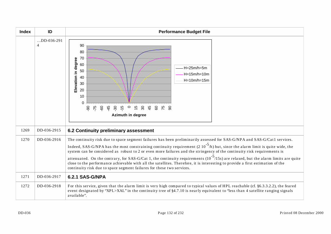
DD-036 Page 132 of 232 Printed 08 December 2000
Index
1269
1270
1271
1272
ID
…DD-036-2914
DD-036-2915
DD-036-2916
DD-036-2917
DD-036-2918
Performance Budget File
0
10
20
30
40
50
60
70
80
90
-90
-75
-60
-45
-30
-15 0 15 30 45 60 75 90
Azimuth in degree
Ele
vati
on
in d
egre
e
H=25m/h=5m
H=15m/h=10m
H=10m/h=15m
6.2 Continuity preliminary assessment
The continuity risk due to space segment failures has been preliminarily assessed for SAS-G/NPA and SAS-G/Cat1 services.
Indeed, SAS-G/NPA has the most constraining continuity requirement (2 10-5
/h) but, since the alarm limit is quite wide, thesystem can be considered as robust to 2 or even more failures and the stringency of the continuity risk requirements is
attenuated. On the contrary, for SAS-G/Cat 1, the continuity requirements (10-5/15s) are relaxed, but the alarm limits are quiteclose to the performance achievable with all the satellites. Therefore, it is interesting to provide a first estimation of thecontinuity risk due to space segment failures for these two services.
6.2.1 SAS-G/NPA
For this service, given that the alarm limit is very high compared to typical values of HPL reachable (cf. §6.3.3.2.2), the fearedevent designated by “XPL>XAL” in the continuity tree of §4.7.10 is nearly equivalent to “less than 4 satellite ranging signalsavailable”.
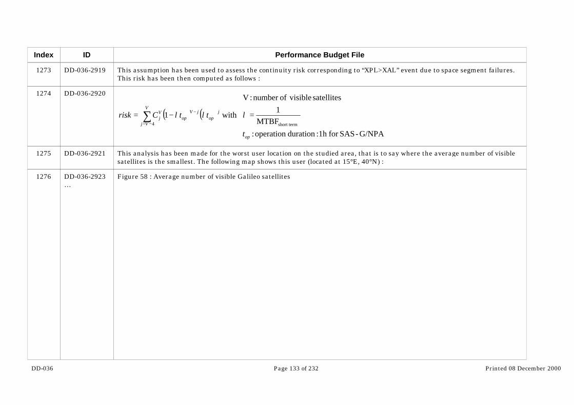
DD-036 Page 133 of 232 Printed 08 December 2000
Index
1273
1274
1275
1276
ID
DD-036-2919
DD-036-2920
DD-036-2921
DD-036-2923…
Performance Budget File
This assumption has been used to assess the continuity risk corresponding to “XPL>XAL” event due to space segment failures.This risk has been then computed as follows :
( ) ( )
=−= ∑−=
−
G/NPA-SASfor 1h :duration operation : MTBF
1satellites visibleofnumber : V
with 1 short term4
op
V
Vj
jop
jVop
Vj
t
ttCrisk λλλ
This analysis has been made for the worst user location on the studied area, that is to say where the average number of visiblesatellites is the smallest. The following map shows this user (located at 15°E, 40°N) :
Figure 58 : Average number of visible Galileo satellites

DD-036 Page 134 of 232 Printed 08 December 2000
Index
1277
ID
…DD-036-2923
DD-036-2924
Performance Budget File
For this identified user, the continuity risk due to space segment failures has been computed for each time step of thesimulation as function of the instantaneous number of visible satellites, as described by the last equation. The result isrepresented on the following figure :

DD-036 Page 135 of 232 Printed 08 December 2000
Index
1278
ID
DD-036-2927…
Performance Budget File
Figure 59 : Continuity risk per hour associated with the number of visible satellites

DD-036 Page 136 of 232 Printed 08 December 2000
Index ID
…DD-036-2927
Performance Budget File
Number of satellites visible from user (15°E, 40°N)
0
2
4
6
8
10
12
0 50 100 150 200 250 300 350
time step
nu
mb
er o
f vi
sib
le s
atel
lites
Continuity risk per hour corresponding to "less than 4 ranging signals available" due to satellite failures for user (15°E, 40°N)
-30
-25
-20
-15
-10
-5
00 50 100 150 200 250 300 350
time step
Co
nti
nu
ity
risk
(10
xx/h
)
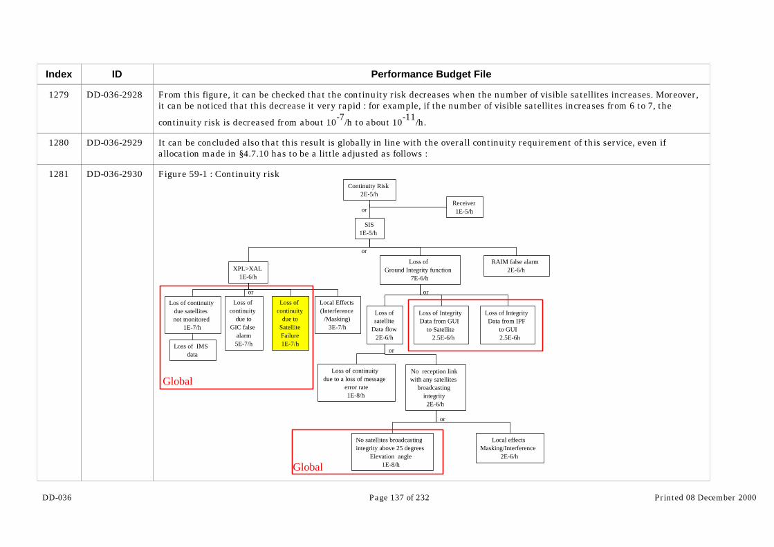
DD-036 Page 137 of 232 Printed 08 December 2000
Index
1279
1280
1281
ID
DD-036-2928
DD-036-2929
DD-036-2930
Performance Budget File
From this figure, it can be checked that the continuity risk decreases when the number of visible satellites increases. Moreover,it can be noticed that this decrease it very rapid : for example, if the number of visible satellites increases from 6 to 7, the
continuity risk is decreased from about 10-7/h to about 10-11/h.
It can be concluded also that this result is globally in line with the overall continuity requirement of this service, even ifallocation made in §4.7.10 has to be a little adjusted as follows :
Figure 59-1 : Continuity risk
SIS1E-5/h
XPL>XAL1E-6/h
Loss ofcontinuity
due toSatelliteFailure1E-7/h
Loss ofcontinuity
due toGIC false
alarm5E-7/h
Los of continuitydue satellitesnot monitored
1E-7/h
Loss of IMSdata
RAIM false alarm2E-6/h
Loss ofGround Integrity function
7E-6/h
No satellites broadcastingintegrity above 25 degrees
Elevation angle1E-8/h
Loss ofsatellite
Data flow2E-6/h
Loss of IntegrityData from IPF
to GUI2.5E-6h
Loss of IntegrityData from GUI
to Satellite2.5E-6/h
No reception linkwith any satellites
broadcastingintegrity2E-6/h
Loss of continuitydue to a loss of message
error rate1E-8/h
Local effectsMasking/Interference
2E-6/h
Receiver1E-5/h
Continuity Risk2E-5/h
Local Effects(Interference
/Masking)3E-7/h
or
or
or
Global
Global
or
or
or

DD-036 Page 138 of 232 Printed 08 December 2000
Index
1282
1283
1284
1285
1286
1287
1288
1289
1290
1291
1292
1293
1294
ID
DD-036-2931
DD-036-2932
DD-036-2933
DD-036-2934
DD-036-2935
DD-036-2936
DD-036-2937
DD-036-2938
DD-036-2939
DD-036-2940
DD-036-2941
DD-036-2942
DD-036-2943
Performance Budget File
With these adjustments, the continuity risk computed in this paragraph seems indeed in line with the corresponding allocation(yellow box).
6.2.2 SAS-G/Cat1
For this service, the assumptions made in the last paragraph are no more valid given that the margins between achievedperformances and requirements are much more reduced.
So in this case, two different assumptions can be considered :
- One satellite failure among the visible satellites is sufficient to loose the service
- Or the service is still available for the single failure cases, and becomes unavailable for 2 satellite failures.
The following equation is used to compute the continuity risk corresponding to each assumption :
( ) ( )
=−= ∑
=
−
service theloose tofailures ofnumber minimal :n
G/NPA-SASfor 1h :duration operation :
MTBF1
satellites visibleofnumber : V
with 1
min
short term
minop
V
nj
jop
jVop
Vj
tttCrisk
λλλ
This leads to continuity risks of about :
- 10-5/15s for the first assumption
- 10-11/15s for the second assumption
So probably, the final figure is between these two results. It shows that allocation made in §4.7.11 for this continuity risk source
(4 10-7/15s) may reveal as difficult to fulfill. This will have to be studied in further details in the next phases of the project.
6.3 Availability assessment

DD-036 Page 139 of 232 Printed 08 December 2000
Index
1295
1296
1297
1298
1299
1300
1301
ID
DD-036-2944
DD-036-2945
DD-036-2946
DD-036-2947
DD-036-2948
DD-036-2949
DD-036-2951…
Performance Budget File
6.3.1 OAS Service
6.3.1.1 OAS-G1
This part is aimed at assessing the availability of accuracy of a single frequency receiver using OAS service in nominalconditions, that is to say with a masking equal to 10° in all the directions. Accuracy requirements taken into account are:
- HNSEreq=16m
- VNSEreq=36m
The availability simulated is presented on the following figure :
Figure 60 : Accuracy availability for OAS-G1

DD-036 Page 140 of 232 Printed 08 December 2000
Index
1302
1303
ID
…DD-036-2951
DD-036-2952
DD-036-2953
Performance Budget File
It can be concluded that availability performances achieved for OAS-G1 service seem compliant with the requirements. Theavailability is indeed greater than 99.4% on the whole studied zone, with a significant part of the area above 99.7%.
The following figures show the average accuracy (HNSE and VNSE) distributions in the case with no satellite failures.

DD-036 Page 141 of 232 Printed 08 December 2000
Index
1305
1306
1307
1308
1309
1310
1311
ID
DD-036-2959
DD-036-2960
DD-036-2961
DD-036-2962
DD-036-2963
DD-036-2964
DD-036-2966…
Performance Budget File
Figure 61 : Average HNSE distribution forOAS-G1
Figure 62 : : Average VNSE distribution forOAS-G1
It appears that margins with respect to requirements are quite good in the case with no satellite failure, specially on the verticalaccuracy (average VNSE is less than 23m on the whole studied zone and requirement is equal to 36m).
6.3.1.2 OAS-G2
In this part, the availability of accuracy of a dual frequency receiver using OAS service in nominal conditions (masking equal to10° in all the directions) is assessed. Accuracy requirements taken into account are those detailed in §4.2 :
- HNSEreq=7m
- VNSEreq=15m
The availability simulated is presented on the following figure :
Figure 63 : Accuracy availability for OAS-G2
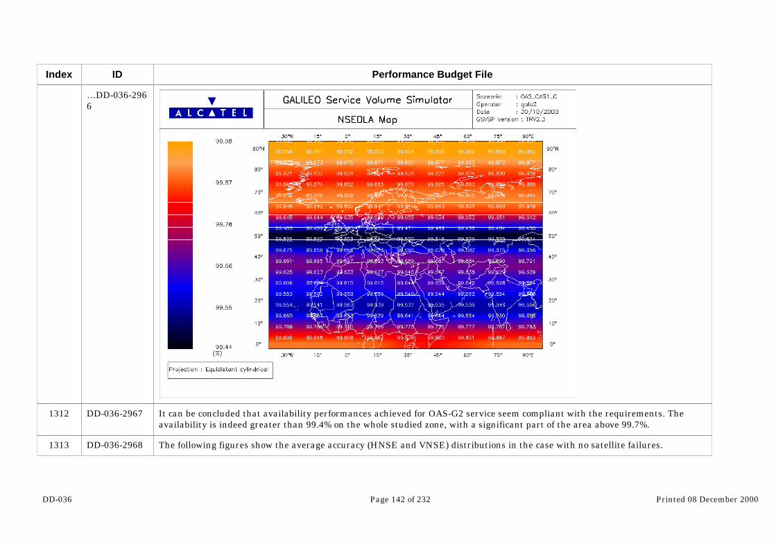
DD-036 Page 142 of 232 Printed 08 December 2000
Index
1312
1313
ID
…DD-036-2966
DD-036-2967
DD-036-2968
Performance Budget File
It can be concluded that availability performances achieved for OAS-G2 service seem compliant with the requirements. Theavailability is indeed greater than 99.4% on the whole studied zone, with a significant part of the area above 99.7%.
The following figures show the average accuracy (HNSE and VNSE) distributions in the case with no satellite failures.

DD-036 Page 143 of 232 Printed 08 December 2000
Index
1315
1316
1317
1318
1319
1320
1321
1322
ID
DD-036-2973
DD-036-2974
DD-036-2975
DD-036-2976
DD-036-2977
DD-036-2978
DD-036-2979
DD-036-2980
Performance Budget File
Figure 64 : Average HNSE distribution forOAS-G2
Figure 65 : Average VNSE distribution forOAS-G2
For OAS-G2, margins with respect to requirements seem quite good when no satellite failures are considered. What can benoticed also, is that the average HNSE is much more uniform on the zone than the average VNSE.
6.3.2 CAS1 service
6.3.2.1 CAS1-G
6.3.2.1.1 Accuracy performance
The CAS1-G accuracy performance is the same as the one obtained for OAS-G2 service (cf. §6.3.1.2) because same UERE, sameother parameters and same requirements are used.
6.3.2.1.2 Integrity performance
The CAS1-G service provides its users with integrity information.

DD-036 Page 144 of 232 Printed 08 December 2000
Index
1323
1324
1325
1326
ID
DD-036-2981
DD-036-2982
DD-036-2983
DD-036-2984
Performance Budget File
So this paragraph is aimed at assessing the availability of integrity for CAS1-G service on a zone representative of Galileoperformances. Alarm limits requirements taken into account are those detailed in §4.2 :
- HAL=20m
- VAL=45m
The integrity availability simulated is presented on the following figure :

DD-036 Page 145 of 232 Printed 08 December 2000
Index
1327
1328
1329
ID
DD-036-2986
DD-036-2987
DD-036-2988
Performance Budget File
Figure 66 : Integrity availability for CAS1-G
This shows that integrity availability performances achieved for CAS1-G service seem compliant with the requirements (99%).The availability is indeed greater than 99.4% on the whole studied zone, with a significant part of the area above 99.7%.
The following figures show the average protection levels (HPL and VPL) distributions in the case with no satellite failures.
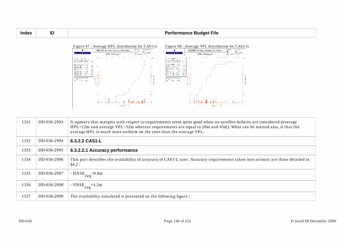
DD-036 Page 146 of 232 Printed 08 December 2000
Index
1331
1332
1333
1334
1335
1336
1337
ID
DD-036-2993
DD-036-2994
DD-036-2995
DD-036-2996
DD-036-2997
DD-036-2998
DD-036-2999
Performance Budget File
Figure 67 : Average HPL distribution for CAS1-G Figure 68 : Average VPL distribution for CAS1-G
It appears that margins with respect to requirements seem quite good when no satellite failures are considered (averageHPL<12m and average VPL<32m whereas requirements are equal to 20m and 45m). What can be noticed also, is that theaverage HPL is much more uniform on the zone than the average VPL.
6.3.2.2 CAS1-L
6.3.2.2.1 Accuracy performance
This part describes the availability of accuracy of CAS1-L user. Accuracy requirements taken into account are those detailed in§4.2 :
- HNSEreq
=0.8m
- VNSEreq=1.2m
The availability simulated is presented on the following figure :

DD-036 Page 147 of 232 Printed 08 December 2000
Index
1338
1339
1340
ID
DD-036-3001
DD-036-3002
DD-036-3003
Performance Budget File
Figure 69 : Accuracy availability for CAS1-L
It can be concluded that availability performances achieved for CAS1-L service are compliant with the requirements (99%) andare even much better. The availability is indeed greater than 99.96% on the whole studied zone.
The following figures show the average accuracy (HNSE and VNSE) distributions in the case with no satellite failures.

DD-036 Page 148 of 232 Printed 08 December 2000
Index
1342
1343
1344
1345
1346
1347
1348
1349
ID
DD-036-3008
DD-036-3009
DD-036-3010
DD-036-3011
DD-036-3012
DD-036-3013
DD-036-3014
DD-036-3016…
Performance Budget File
Figure 70 : Average HNSE distribution forCAS1-L
Figure 71 : Average VNSE distribution forCAS1-L
In these figures, important margins with respect to requirements that could already be foreseen from the average accuracyavailability obtained in Figure 69 are confirmed.
6.3.2.2.2 Integrity performance
The CAS1-L service provides its users with integrity information.
The availability of integrity for this service on a zone representative of Galileo performances is here assessed. Alarm limitsrequirements taken into account are those detailed in §4.2 :
- HAL=2m
- VAL=3.5m
The integrity availability simulated is presented on the following figure :
Figure 72 : Integrity availability for CAS1-L

DD-036 Page 149 of 232 Printed 08 December 2000
Index
1350
1351
ID
…DD-036-3016
DD-036-3017
DD-036-3018
Performance Budget File
This figure shows that availability performances achieved for CAS1-L service are compliant with the requirements (99%) andeven much better. The availability is indeed greater than 99.96% on the whole studied zone.
The following figures show the average protection levels (HPL and VPL) distributions in the case with no satellite failures. Theyconfirm the important margins with respect to requirements that could already be foreseen from the average UIM availabilityobtained in Figure 72.

DD-036 Page 150 of 232 Printed 08 December 2000
Index
1353
1354
1355
1356
1357
1358
1359
1360
ID
DD-036-3023
DD-036-3024
DD-036-3025
DD-036-3026
DD-036-3027
DD-036-3028
DD-036-3029
DD-036-3031…
Performance Budget File
Figure 73 : Average HPL distribution for CAS1-L Figure 74 : Average VPL distribution for CAS1-L
6.3.3 SAS and GAS Services
6.3.3.1 SAS-G/En route
6.3.3.1.1 Accuracy performance
The availability of accuracy of SAS-G/En Route user is assessed in this. Accuracy requirements taken into account are thosedetailed in §4.2 :
- HNSEreq=100m
- VNSEreq=NA
The availability simulated is presented on the following figure :
Figure 75 : Accuracy availability for SAS-G/En Route
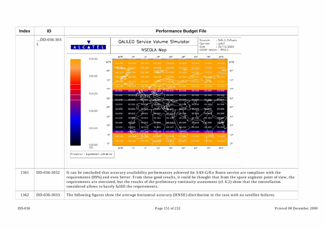
DD-036 Page 151 of 232 Printed 08 December 2000
Index
1361
1362
ID
…DD-036-3031
DD-036-3032
DD-036-3033
Performance Budget File
It can be concluded that accuracy availability performances achieved for SAS-G/En Route service are compliant with therequirements (99%) and even better. From these good results, it could be thought that from the space segment point of view, therequirements are oversized, but the results of the preliminary continuity assessment (cf. 6.2) show that the constellationconsidered allows to barely fulfill the requirements.
The following figures show the average horizontal accuracy (HNSE) distribution in the case with no satellite failures.

DD-036 Page 152 of 232 Printed 08 December 2000
Index
1364
1365
1366
1367
1368
1369
1370
ID
DD-036-3037
DD-036-3038
DD-036-3039
DD-036-3040
DD-036-3041
DD-036-3042
DD-036-3043
Performance Budget File
Figure 76 : Average HNSE distribution forSAS-G/En Route
From this figure, important margin with respect to requirement that could already be foreseen from the average accuracyavailability obtained in Figure 75 is confirmed (maximal value of average HNSE reached on the zone is equal to 2.54m whereasrequirement is equal to 100m). This result is not surprising given that SAS-G signal (and so UERE budget) is dimensioned forproviding Cat1 performances.
6.3.3.1.2 Integrity performance
The SAS-G/En Route service provides its users with integrity information, using a RAIM algorithm.
So this paragraph studies the availability of integrity for SAS-G/En Route service on a zone representative of Galileoperformances. Alarm limits requirements taken into account are those detailed in §4.2 :
- HAL=556m
- VAL=NA
The integrity availability simulated is presented on the following figure :

DD-036 Page 153 of 232 Printed 08 December 2000
Index
1371
1372
ID
DD-036-3045
DD-036-3046
Performance Budget File
Figure 77 : Integrity availability for SAS-G/En Route
This shows that UIM availability performances achieved for SAS-G/En Route service are compliant with the requirements (99%)and even better. The availability is indeed greater than 99.9% on the whole studied zone. It should be noted however, that theseresults have been obtained with space segment failure assumptions that must be considered as a little optimistic (MTTR equalto the in-orbit spares figure), which effect could be very important on the RAIM availability.

DD-036 Page 154 of 232 Printed 08 December 2000
Index
1373
1375
1376
1377
1378
1379
1380
1381
ID
DD-036-3047
DD-036-3051
DD-036-3052
DD-036-3053
DD-036-3054
DD-036-3055
DD-036-3056
DD-036-3057
Performance Budget File
The following figures show the average horizontal protection levels (HPL) distribution in the case with no satellite failures.
Figure 78 : Average HPL distribution forSAS-G/En Route
The important margin with respect to requirement that could already be foreseen from the average integrity availabilityobtained in Figure 77 is confirmed here (maximal value of average HPL reached on the zone is equal to 13.91m whereasrequirement is equal to 556m).
6.3.3.2 SAS-G/NPA
6.3.3.2.1 Accuracy performance
As requirements are the same as for SAS-G/En route (except for the availability that must be greater than 99.9%) and otherparameters are also the same, refer to §6.3.3.1.1 for the accuracy performance analysis.
From this paragraph, it can be concluded that the system is compliant to the accuracy requirements as accuracy availability isgreater than 99.9% on the whole studied zone.
6.3.3.2.2 Integrity performance
The SAS-G/NPA service provides its users with integrity information.

DD-036 Page 155 of 232 Printed 08 December 2000
Index
1382
1383
ID
DD-036-3058
DD-036-3060
Performance Budget File
Corresponding requirements are the same as for SAS-G/En Route but have to be met with an availability of 99.9% (in place of99% for SAS-G/En Route). This leads to the use of a GIC algorithm because, although RAIM availability is above 99.9% onFigure 77, this has been achieved with optimistic satellites failures assumptions (in orbit spares always considered), which isdeterminant for RAIM availability. The integrity availability simulated is presented on the following figure :
Figure 79 : Integrity availability for SAS-G/NPA

DD-036 Page 156 of 232 Printed 08 December 2000
Index
1384
1385
1387
1388
1389
ID
DD-036-3061
DD-036-3062
DD-036-3066
DD-036-3067
DD-036-3068
Performance Budget File
It can be concluded from this map that integrity availability performances achieved for SAS-G/NPA service are compliant withthe requirements (99.9%) and even better. However, it must be noted that accuracy of the simulation (only up to 3 satellitesfailures among visible satellites are considered) is not sufficient to allow a more precise characterization (above 99.9%) of theavailability figures. In addition, from these good results, it could be thought that from the space segment point of view, therequirements are oversized, but the results of the preliminary continuity assessment (cf. 6.2) show that the constellationconsidered allows to barely fulfill the requirements.
The following figure shows the average horizontal protection level (HPL) distribution in the case with no satellite failures.
Figure 80 : Average HPL distribution forSAS-G/NPA
This confirms important margin with respect to requirement that could already be foreseen from the average integrityavailability obtained in Figure 79 (maximal value of average HPL reached on the zone is equal to 6.78m whereas requirement isequal to 556m). This result is not surprising given that SAS-G signal (and so UERE budget) is dimensioned for providing Cat1performances.
6.3.3.3 SAS-G/Cat1 and GAS-G
As all parameters defining SAS-G/Cat1 and GAS-G services are the same, only one simulation has been made. The differencebetween these two services is indeed at the level of control access management.

DD-036 Page 157 of 232 Printed 08 December 2000
Index
1390
1391
1392
1393
1394
1395
ID
DD-036-3069
DD-036-3070
DD-036-3071
DD-036-3072
DD-036-3073
DD-036-3075…
Performance Budget File
6.3.3.3.1 Accuracy performance
This part is aimed at assessing the availability of accuracy of SAS-G/Cat1 and GAS-G users. Accuracy requirements taken intoaccount are those detailed in §4.2 :
- HNSEreq=6m
- VNSEreq=6m
The accuracy availability simulated is presented on the following figure :
Figure 81 : Accuracy availability for SAS-G/Cat1 and GAS-G
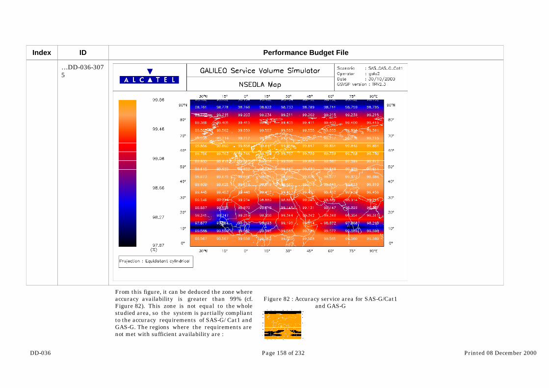
DD-036 Page 158 of 232 Printed 08 December 2000
Index ID
…DD-036-3075
Performance Budget File
From this figure, it can be deduced the zone whereaccuracy availability is greater than 99% (cf.Figure 82). This zone is not equal to the wholestudied area, so the system is partially compliantto the accuracy requirements of SAS-G/ Cat1 andGAS-G. The regions where the requirements arenot met with sufficient availability are :
Figure 82 : Accuracy service area for SAS-G/Cat1and GAS-G

DD-036 Page 159 of 232 Printed 08 December 2000
Index ID Performance Budget File
• A latitude band situated above 85°N.• Some regions located between 10°N and25°N latitude.
The following figures show the average accuracy(HNSE and VNSE) distributions in the case withno satellite failures.
Figure 83 : Average HNSE distribution forSAS-G/Cat1 and GAS-G
Figure 84 : Average VNSE distribution forSAS-G/Cat1 and GAS-G

DD-036 Page 160 of 232 Printed 08 December 2000
Index
1398
1399
1400
1401
1402
1403
1404
1405
ID
DD-036-3084
DD-036-3085
DD-036-3086
DD-036-3087
DD-036-3088
DD-036-3089
DD-036-3090
DD-036-3091…
Performance Budget File
It appears that the margin between average HNSE and the corresponding requirement seems correct (maximum value ofaverage HNSE is 2.54m wrt a requirement of 6m) whereas the margin between average VNSE and required vertical accuracy isvery reduced with respect to results obtained for the other services (maximal average value reached is 5.24m wrt a requirementof 6m also). This certainly explains the availability holes observed on Figure 82.
6.3.3.3.2 Integrity performance
The SAS-G/Cat1 and GAS-G services provide their users with integrity information.
So this paragraph presents the availability of integrity for SAS-G/Cat1 and GAS-G services on a zone representative of Galileoperformances. Alarm limits requirements taken into account are those detailed in §4.2 :
HAL=11m
VAL=15m
The integrity availability simulated is illustrated by the following figure :

DD-036 Page 161 of 232 Printed 08 December 2000
Index
1406
1407
1408
ID
…DD-036-3091
DD-036-3092
DD-036-3093
DD-036-3094
Performance Budget File
Figure 85 : Integrity availability for SAS-G/Cat1 and GAS-G
It appears that integrity availability performances achieved for SAS-G/Cat1 and GAS-G services seem very poor. Theavailability is indeed greater than 99% only for some users located on a latitude band at 60°N. However, it must be noted thatthese results have been achieved with the following sizing parameters :
A 10° mask angle

DD-036 Page 162 of 232 Printed 08 December 2000
Index
1409
1410
1411
1413
1414
1415
1416
ID
DD-036-3095
DD-036-3096
DD-036-3097
DD-036-3102
DD-036-3103
DD-036-3104
DD-036-3105
Performance Budget File
A high multipath budget
Sensitivity of the SAS-G/ Cat1 and GAS-G performances to these sizing parameters will be studied in §6.3.4.
The following figures show the average protection levels (HPL and VPL) distributions in the case with no satellite failures.
Figure 86 : Average HPL distribution forSAS-G/Cat1 and GAS-G
Figure 87 : Average VPL distribution forSAS-G/Cat1 and GAS-G
From these figures, the margin between average HPL and the corresponding requirement seems correct (maximum value ofaverage HPL is 6.32m wrt a requirement of 11m) whereas the margin between average VPL and vertical alarm limit is negative: VAL value is overshot by some average VPL even when no satellite failures are introduced (maximal average value reached is15.95m wrt a requirement of 15m). This explains the poor availability noticed on Figure 85.
6.3.3.4 SAS-R
SAS-R service is equivalent to SAS-G. Indeed, it has been defined for regions different from Europe that may have the intentionto implement regional service under their responsibility. So performances are the same as the ones obtained for SAS-G (cf. lastparagraph).
6.3.3.5 SAS-L and GAS-L

DD-036 Page 163 of 232 Printed 08 December 2000
Index
1417
1418
1419
1420
1421
1422
1423
ID
DD-036-3106
DD-036-3107
DD-036-3108
DD-036-3109
DD-036-3110
DD-036-3111
DD-036-3112…
Performance Budget File
As all parameters defining SAS-L and GAS-L services are the same, only one simulation has been made. The difference betweenthese two services is indeed at the level of control access management.
6.3.3.5.1 Accuracy performance
This part is aimed at assessing the availability of accuracy of SAS-L and GAS-L users. Accuracy requirements taken intoaccount are those detailed in the mission requirements :
HNSEreq=1m
VNSEreq=1.5m
The accuracy availability simulated is presented on the following figure :

DD-036 Page 164 of 232 Printed 08 December 2000
Index
1424
1425
1426
ID
…DD-036-3112
DD-036-3113
DD-036-3114
DD-036-3115
Performance Budget File
Figure 88 : Accuracy availability for SAS-L and GAS-L
It shows that availability performances achieved for SAS-L and GAS-L services are compliant with the requirements (99.9%)and even better. However, as already mentioned, the accuracy of the simulation is not sufficient to allow a more precisecharacterization (above 99.9%) of the availability figures.
The following figures give the average accuracy (HNSE and VNSE) distributions in the case with no satellite failures.

DD-036 Page 165 of 232 Printed 08 December 2000
Index
1428
1429
1430
1431
1432
1433
1434
1435
ID
DD-036-3120
DD-036-3121
DD-036-3122
DD-036-3123
DD-036-3124
DD-036-3125
DD-036-3126
DD-036-3127…
Performance Budget File
Figure 89 : Average HNSE distribution for SAS-Land GAS-L
Figure 90 : Average VNSE distribution for SAS-Land GAS-L
From these figures, good margins with respect to requirements that could already be foreseen from the average accuracyavailability obtained in Figure 88 are confirmed.
6.3.3.5.2 Integrity performance
The SAS-L and GAS-L services provide their users with integrity information.
So in this paragraph the availability of integrity for SAS-L and GAS-L services on a zone representative of Galileo performancesis assessed. Alarm limits requirements taken into account are those detailed in the mission requirements :
HAL=3m
VAL=5.5m
The integrity availability simulated is presented on the following figure :

DD-036 Page 166 of 232 Printed 08 December 2000
Index
1436
1437
1438
ID
…DD-036-3127
DD-036-3128
DD-036-3129
DD-036-3130
Performance Budget File
Figure 91 : Integrity availability for SAS-L and GAS-L
It can be concluded that integrity availability performances achieved for SAS-L and GAS-L services are also compliant with therequirements (99.9%). However, as already mentioned, the accuracy of the simulation is not sufficient to allow a more precisecharacterization (above 99.9%) of the availability figures.
The following figures show the average protection levels (HPL and VPL) distributions in the case with no satellite failures.

DD-036 Page 167 of 232 Printed 08 December 2000
Index
1440
1441
1442
1443
1444
1445
1446
1447
ID
DD-036-3135
DD-036-3136
DD-036-3137
DD-036-3138
DD-036-3139
DD-036-3140
DD-036-3141
DD-036-3142
Performance Budget File
Figure 92 : Average HPL distribution for SAS-Land GAS-L
Figure 93 : Average VPL distribution for SAS-Land GAS-L
They confirm good margins with respect to requirements that could already be foreseen from the average accuracy availabilityobtained in Figure 91.
6.3.4 Sensitivity analysis
Sensitivity analysis have been done for SAS-G / Cat1 and GAS-G services only because the performances achieved for all otherservices are compliant with the requirements, when the baseline simulation parameters are used. In particular the followingsensitivity studies have been performed :
Sensitivity to the multipath error budget
Sensitivity to the user mask angle
Sensitivity to the horizontal / vertical allocation of the integrity risk
Sensitivity to the vertical alarm limit value
6.3.4.1 Sensitivity to the multipath error budget

DD-036 Page 168 of 232 Printed 08 December 2000
Index
1448
1449
1450
1451
ID
DD-036-3143
DD-036-3144
DD-036-3145
DD-036-3146
Performance Budget File
In §4, two UERE budgets are presented :
One taking into account pessimistic assumptions for multipath. This budget is the one that has been used to assess baselineperformances in the last paragraph.
Another taking into account lower multipath environment. The results presented in the current paragraph correspond to thisbudget.
The following map represents the average accuracy availability obtained with this new assumption, all other simulationparameters being kept at the same values (baseline assumptions described in §6.1).

DD-036 Page 169 of 232 Printed 08 December 2000
Index
1452
1453
1454
1455
ID
DD-036-3147
DD-036-3148
DD-036-3149
DD-036-3150
Performance Budget File
Figure 94 : SAS-G/Cat1 and GAS-G accuracy availability for low multipath conditions
From this map, SAS-G/Cat1 and GAS-G accuracy availability performances seem compliant with the requirements with thesemultipath conditions. The availability is indeed greater than 99.4% on the whole studied zone, with the main part of the areacovered with an availability better than 99.7% (only three users are below this figure).
The next map shows the UIM availability performances achieved in the same multipath conditions :
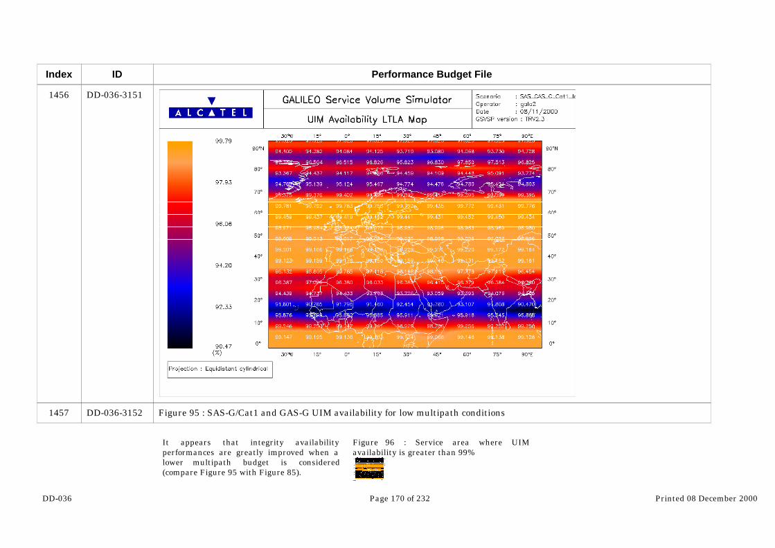
DD-036 Page 170 of 232 Printed 08 December 2000
Index
1456
1457
ID
DD-036-3151
DD-036-3152
Performance Budget File
Figure 95 : SAS-G/Cat1 and GAS-G UIM availability for low multipath conditions
It appears that integrity availabilityperformances are greatly improved when alower multipath budget is considered(compare Figure 95 with Figure 85).
Figure 96 : Service area where UIMavailability is greater than 99%

DD-036 Page 171 of 232 Printed 08 December 2000
Index
1459
1460
1461
ID
DD-036-3157
DD-036-3158
DD-036-3159
Performance Budget File
The UIM availability is still below therequirement (99%) for some regions of thestudied zone (latitude comprised between10°N and 30°N and above 70°N), but asignificant part of the zone is, in theseconditions, covered with the requiredavailability (cf. Figure 96).
6.3.4.2 Sensitivity to the user mask angle
Baseline results presented in §6.3.3.3 were achieved with a user mask angle equal to 10°. As for SAS and GAS users, theenvironment can be more open, the sensitivity of their performances to the mask angle value has been studied by assessing theimpact of reducing it to 5° (all other parameters being kept to their baseline values described in §6.1). This value is actually inline with the MOPS requirement.
First the impact of this change on the average number of visible satellites from the user is presented on the following figures :

DD-036 Page 172 of 232 Printed 08 December 2000
Index
1463
1464
ID
DD-036-3164
DD-036-3165…
Performance Budget File
Figure 97 : Average number of visible satellitesseen with a mask angle of 10°
Figure 98 : Average number of visible satellitesseen with a mask angle of 5°
The impact of reducing the user mask angle from 10° to 5° is a significant increase of the number of visible satellites : theaverage values are indeed quasi-uniformly increased by one. Then, an improvement of availability figures can be foreseen : itcan be checked on the following maps representing the accuracy and the integrity availability.
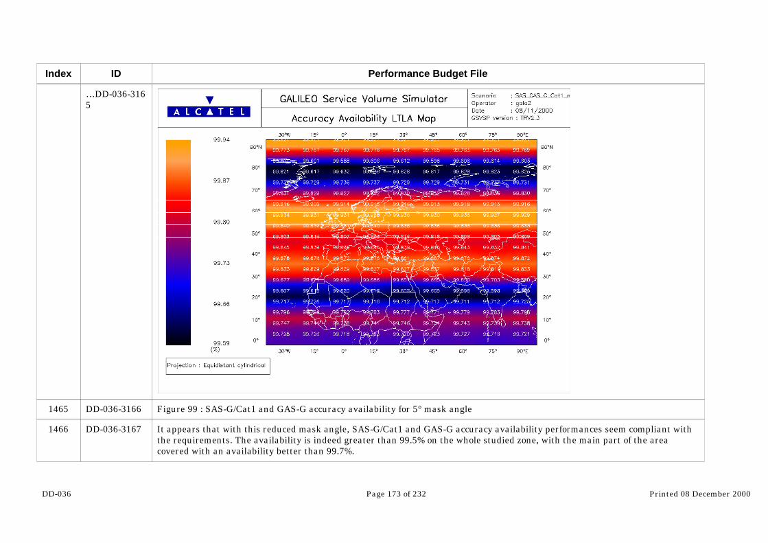
DD-036 Page 173 of 232 Printed 08 December 2000
Index
1465
1466
ID
…DD-036-3165
DD-036-3166
DD-036-3167
Performance Budget File
Figure 99 : SAS-G/Cat1 and GAS-G accuracy availability for 5° mask angle
It appears that with this reduced mask angle, SAS-G/Cat1 and GAS-G accuracy availability performances seem compliant withthe requirements. The availability is indeed greater than 99.5% on the whole studied zone, with the main part of the areacovered with an availability better than 99.7%.

DD-036 Page 174 of 232 Printed 08 December 2000
Index
1467
1468
1469
ID
DD-036-3168
DD-036-3169
DD-036-3170
Performance Budget File
Figure 100 : SAS-G/Cat1 and GAS-G UIM availability for 5° mask angle
Integrity availability performances are also well improved when a lower mask angle is considered (compare with Figure 85).The UIM availability is still below the requirement (99%) for some regions of the studied zone (latitude comprised between 10°Nand 30°N and above 70°N), but a great part of the zone is, in these conditions, covered with the required availability. It can benoticed also that the improvement observed in this sensitivity case in less important than for the reduction of multipath level.

DD-036 Page 175 of 232 Printed 08 December 2000
Index
1470
1471
1472
1474
1475
1476
1477
1478
ID
DD-036-3171
DD-036-3172
DD-036-3173
DD-036-3178
DD-036-3179
DD-036-3180
DD-036-3181
DD-036-3182
Performance Budget File
6.3.4.3 Sensitivity to the horizontal / vertical allocation of the integrity risk
In the baseline simulation, the integrity risk has been allocated equally on the vertical and horizontal dimension.
Now, when an analysis of the causes of outages occurring in the nominal conditions (no satellite failures) is made (cf. thefollowing figures), it shows that all the outages correspond to VPL overshooting the VAL.
Figure 101 : HPL analysis during outages Figure 102 : VPL analysis during outages
Indeed, it can be noticed that during outage periods, HPL reaches at a maximum 7.81m (wrt a requirement of 11m) whereas,VPL values are always above the alarm limit and are comprised between 15m and 21.3m.
From these results, it can be tried to change the allocation of the integrity risk between horizontal and vertical components.
In the baseline, the total integrity risk allocated to GIC (fault free case) is equal to 1 10-7/150s (=1 10-7 per independent sample)and is allocated equally to horizontal and vertical dimensions, that is to say :
5 10-8 on the horizontal dimension, which corresponds to 5.45σ on the gaussian distribution
5 10-8 on the vertical dimension, which corresponds to 5.45σ on the gaussian distribution

DD-036 Page 176 of 232 Printed 08 December 2000
Index
1479
1480
1481
1482
1483
1484
ID
DD-036-3183
DD-036-3184
DD-036-3185
DD-036-3186
DD-036-3187
DD-036-3188…
Performance Budget File
So this coefficient (5.45) has been used both in the horizontal and in the vertical protection level computations.
Now, taking into account outage analysis presented above, this allocation could be changed to be more constraining on thehorizontal dimension where margin has been observed and less constraining on the vertical one. An example of adaptation ofthis allocation is :
10-10 on the horizontal dimension, which corresponds to 6.47σ on the gaussian distribution
~1 10-7 on the vertical dimension, which corresponds to 5.33σ on the gaussian distribution
Taking into account this new allocation, and all other parameters being kept at their baseline values, the UIM availability hasbeen recomputed and compared to the availability achieved in the baseline case. The result of this comparison is presented onthe following figure :

DD-036 Page 177 of 232 Printed 08 December 2000
Index
1485
1486
ID
…DD-036-3188
DD-036-3189
DD-036-3190
Performance Budget File
Figure 103 : Difference between UIM availability achieved with the new allocation and with the baseline one
From Figure 103, it appears that the newallocation globally improves the UIM availability,except for a particular zone located at 60° latitude
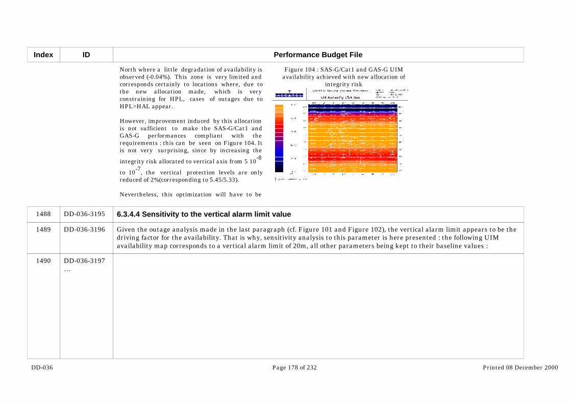
DD-036 Page 178 of 232 Printed 08 December 2000
Index
1488
1489
1490
ID
DD-036-3195
DD-036-3196
DD-036-3197…
Performance Budget File
North where a little degradation of availability isobserved (-0.04%). This zone is very limited andcorresponds certainly to locations where, due tothe new allocation made, which is veryconstraining for HPL, cases of outages due toHPL>HAL appear.
However, improvement induced by this allocationis not sufficient to make the SAS-G/Cat1 andGAS-G performances compliant with therequirements : this can be seen on Figure 104. Itis not very surprising, since by increasing the
integrity risk allocated to vertical axis from 5 10-8
to 10-7, the vertical protection levels are onlyreduced of 2%(corresponding to 5.45/5.33).
Nevertheless, this optimization will have to be
Figure 104 : SAS-G/Cat1 and GAS-G UIMavailability achieved with new allocation of
integrity risk
6.3.4.4 Sensitivity to the vertical alarm limit value
Given the outage analysis made in the last paragraph (cf. Figure 101 and Figure 102), the vertical alarm limit appears to be thedriving factor for the availability. That is why, sensitivity analysis to this parameter is here presented : the following UIMavailability map corresponds to a vertical alarm limit of 20m, all other parameters being kept to their baseline values :

DD-036 Page 179 of 232 Printed 08 December 2000
Index
1491
1492
ID
…DD-036-3197
DD-036-3198
DD-036-3199
Performance Budget File
Figure 105 : SAS-G/Cat1 and GAS-G UIM availability for VAL=20m
It can be deduced that with a vertical alarm limit of 20m, the UIM availability is greatly improved and is compliant with therequirement (99%) on the main part of the zone. Only a latitude band located at 10°N shows some availability holes. Availabilitylevel achieved at these locations is nevertheless very near of 98%.

DD-036 Page 180 of 232 Printed 08 December 2000
Index
1493
1494
1495
1496
ID
DD-036-3200
DD-036-3201
DD-036-3202
DD-036-3203
Performance Budget File
6.3.4.5 Sensitivity to the vertical accuracy requirement value
From Figure 82, the system is only partially compliant to the accuracy requirements. Given the results of an outage analysisanalog to the one presented in Figure 101 and Figure 102, it appears that the vertical accuracy requirement is the driving factorfor the accuracy availability. Therefore a sensitivity analysis to this parameter is here presented.
The following map corresponds to a vertical accuracy requirement of 6.3m. It represents the service area where the accuracyavailability is above 99% :

DD-036 Page 181 of 232 Printed 08 December 2000
Index
1497
1498
ID
DD-036-3204
DD-036-3205
Performance Budget File
Figure 106 : SAS-G/Cat1 accuracy service area at 99% for VNSEreq=6.3m
It can be deduced that, by increasing the vertical accuracy requirement of only 30cm, the non compliance observed on Figure 82at the pole, is overcome. On the contrary, on the zone close to the equator, this requirement adaptation is not sufficient : it isnecessary to increase this value to 6.8m to have a full compliance on the whole zone.
DD-036 Page 182 of 232 Printed 08 December 2000
Index
1499
1500
1501
1502
1503
1504
1505
1506
1507
1508
1509
1510
1511
ID
DD-036-3206
DD-036-3207
DD-036-3208
DD-036-3209
DD-036-3210
DD-036-3211
DD-036-3212
DD-036-3213
DD-036-3214
DD-036-3215
DD-036-3216
DD-036-3217
DD-036-3218
Performance Budget File
7 Performance with External system
7.1 Global Positioning System (GPS+)
7.1.1 Assumptions
At the edge of 2008 the GPS system will be different from what it is today. The current GPS satellites will be replaced by the GPSblock IIF satellites. They are the next generation satellites that will be launched starting in late 2001 (TBC) to replace the IIA andIIR vehicles. The Block IIF is assumed to provide significant enhancements over the IIA and IIR. The design enhancement issupposed to lead to a lower URE and lower positioning error. The design enhancement concerns:
Better performance of the frequency standards
Reduction in the age of data of the broadcast navigation message to <3 hours
Provision for C/A code and P-code on L2
Provision of a third frequency in ARNS band: L5
Increased user received power level
A detailed description of what would be the GPS system is available in Integrity Trade-off deliverable [RD-07]. The relevantparameter for performance assessment are recalled here after.
7.1.1.1 Constellation parameter
7.1.1.1.1 GPS constellation parameter
The constellation parameters used to simulate GPS are the same as the ones of the current constellation. The number ofsatellites is 24 spread on 6 plans with 4 satellites per plan. One could argue that the constellation will most likely evolved inthe future in the frame of GPS upgrade. According to [RD-017], the number of satellite may increase from 24 to 30 in thefuture. Nevertheless, the results obtained with the 24 satellite constellation can be interpreted as a minimal bound of theperformance that can be achieved combining Galileo and GPS all together. The GPS orbital parameters used for the simulationcan be found in ANNEX A.

DD-036 Page 183 of 232 Printed 08 December 2000
Index
1512
1513
1514
1515
1516
ID
DD-036-3219
DD-036-3220
DD-036-3221
DD-036-3222
DD-036-3223
Performance Budget File
One issue when combining Galileo and GPS is that the periods of the constellations are not identical. Therefore oneconstellation will move slowly comparing to the other and the performance of the combined system may change with the years. This issue has been addressed in [RD-06]. It shows that the difference of performance due to this effect is marginal.
7.1.1.2 UERE
As for the constellation, GPS signal will most likely evolve in the future. Up to now the civil signal was concentrated on a singlecarrier L1 with a chip rate of 1.023 Mchips/s. In the future the carrier L2 that is currently dedicated to military used will beavailable to the civil community. Furthermore, a third frequency on L5 with a high chip rate will also be available to civil user. Therefore the structure of the signal will be quite similar to the Galileo one. A civil receiver will probably uses the L1 and L5carriers to correct ionospheric delay. The following figure shows the GPS UERE deduced from offical source (DoD/DoT) and theUERE computed in the frame of GALA taken into account the GPS block IIF signal structure and the SAS user assumptions. The UERE appear quite similar. The major difference is on the low elevation angle. This comes from more optimistic value formulitpath budget. It is also interesting to note that the budget for clock and ephemeris error is equal to 1.2 m (DoD/DoT)whereas for Galileo, this budget is equal to 0.65 m.
0
1
2
3
4
5
6
5 10 15 20 25 30 35 40 45 50 55 60 65 70 75 80 85 90
Elevation Angle
Err
or
at 1
sig
ma
in m
DoD/DoTGALA
Figure 107: GPS UERE budget

DD-036 Page 184 of 232 Printed 08 December 2000
Index
1517
1518
1519
1520
1521
1522
1523
1524
ID
DD-036-3224
DD-036-3225
DD-036-3226
DD-036-3227
DD-036-3228
DD-036-3229
DD-036-3230
DD-036-3231…
Performance Budget File
For performance estimation the GPS UERE computed with GALA assumptions will be used.
7.1.2 Combined Galileo/GPS Navigation Performance
7.1.2.1 Performance of GPS only
The following graph shows the performance of GPS, without any augmentation such as SBAS or GBAS. For safety of lifeapplication the availability targeted is 99.9% (SAS requirement in line with CAT1). The following map shows the availabilityof GPS for a vertical accuracy of 30 meters. We can see that the availability is quite good on the main part of the globe butdecreases drastically in certain area. Basically, the performance got from GPS are much worse than the ones expected fromGalileo for three reasons:
The UERE is degraded comparing to the ones expected for Galileo because of signals less powerful and an error oforbito-synchro larger (1.2 meter instead of 0.65 meter). The better performance of Galileo on this budget relies on the fact thatthe clocks are assumed as stable as the GPS ones and the update rate of the clock and ephemeris data is faster than for GPS. Itis worth to be noted that with SBAS augmentation, this budget can be reduced back to 0.65m
Galileo satellites are more numerous than GPS ones (30 instead of 24). It is sure than this assumptions is questionable sincecurrently the number of GPS satellites is equal to 27. However, no one knows how the constellation will evolve in the future. For the moment the only official source is the GPS-ICD from US DoD. In this document it is stated that the GPS constellationincludes 24 satellites. Once this document is updated, this assumption can be reviewed.
The GPS constellation is not symmetrical. Therefore, as shown in the following maps, GPS has very poor availability on somearea. This has very penalizing effect on the performance of the system. Indeed it is very difficult (almost impossible) toguaranty a “good” service on a wide area with this kind of worm hole inside.

DD-036 Page 185 of 232 Printed 08 December 2000
Index
1525
1526
ID
…DD-036-3231
DD-036-3232
DD-036-3233…
Performance Budget File
Figure 108: GPS vertical Availability (VNSE=30m)

DD-036 Page 186 of 232 Printed 08 December 2000
Index
1527
1528
1529
1530
1531
ID
…DD-036-3233
DD-036-3234
DD-036-3235
DD-036-3236
DD-036-3237
DD-036-3238
Performance Budget File
Figure 109: GPS VNSE average
7.1.2.2 Baseline Availability of Service for combined use of GPS and Galileo
7.1.2.2.1 OAS-GS
This part is aimed at assessing the availability of accuracy of a user using both OAS service of Galileo and GPS in nominalconditions, that is to say with a masking equal to 10° in all the directions. Accuracy requirements taken into account are thosedetailed in the mission requirements :
HNSEreq=4m
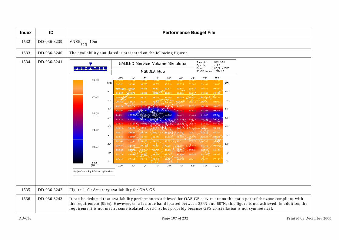
DD-036 Page 187 of 232 Printed 08 December 2000
Index
1532
1533
1534
1535
1536
ID
DD-036-3239
DD-036-3240
DD-036-3241
DD-036-3242
DD-036-3243
Performance Budget File
VNSEreq=10m
The availability simulated is presented on the following figure :
Figure 110 : Accuracy availability for OAS-GS
It can be deduced that availability performances achieved for OAS-GS service are on the main part of the zone compliant withthe requirement (99%). However, on a latitude band located between 35°N and 60°N, this figure is not achieved. In addition, therequirement is not met at some isolated locations, but probably because GPS constellation is not symmetrical.

DD-036 Page 188 of 232 Printed 08 December 2000
Index
1537
1539
1540
1541
1542
1543
1544
ID
DD-036-3244
DD-036-3249
DD-036-3250
DD-036-3251
DD-036-3252
DD-036-3253
DD-036-3254
Performance Budget File
The following figures show the average accuracy (HNSE and VNSE) distributions in the case with no satellite failures.
Figure 111 : Average HNSE distribution forOAS-GS
Figure 112 : Average VNSE distribution forOAS-GS
They confirm that the margins with respect to requirements are quite reduced for OAS-GS service, particularly for horizontalaccuracy.
7.1.2.2.2 CAS1-GS
7.1.2.2.2.1 Accuracy performance
In this part is studied the availability of accuracy of a user using both CAS1-G service of Galileo and GPS (with SBAS, implyingthat UERE of GPS can be considered as equivalent as the one achieved with Galileo) in nominal conditions, that is to say with amasking equal to 10° in all the directions. Accuracy requirements taken into account are those detailed in the missionrequirements :
HNSEreq=4m

DD-036 Page 189 of 232 Printed 08 December 2000
Index
1545
1546
1547
1548
ID
DD-036-3255
DD-036-3256
DD-036-3257
DD-036-3258
Performance Budget File
VNSEreq=10m
The availability simulated is presented on the following figure :
Figure 113 : Accuracy availability for CAS1-GS

DD-036 Page 190 of 232 Printed 08 December 2000
Index
1549
1550
1552
1553
1554
1555
1556
1557
1558
ID
DD-036-3259
DD-036-3260
DD-036-3265
DD-036-3266
DD-036-3267
DD-036-3268
DD-036-3269
DD-036-3270
DD-036-3271
Performance Budget File
It can be concluded that availability performances achieved for CAS1-GS service are on the main part of the zone compliantwith the requirement (99%). However, on a latitude band located between 35°N and 60°N, this figure is not achieved. Moreover,it must be noted that performances are globally better than for OAS-GS, due to the use of Galileo UERE assumptions also forGPS satellites.
The following figures show the average accuracy (HNSE and VNSE) distributions in the case with no satellite failures.
Figure 114 : Average HNSE distribution for CAS1-GS Figure 115 : Average VNSE distribution for CAS1-GS
The same remark as for OAS-GS can be made on the reduced margins.
7.1.2.2.2.2 Integrity performance
The CAS1-GS service provides its users with integrity information.
Alarm limits requirements taken into account are those detailed in §in the mission requirements :
HAL=13m
VAL=32m

DD-036 Page 191 of 232 Printed 08 December 2000
Index
1559
1560
1561
1562
ID
DD-036-3272
DD-036-3273
DD-036-3274
DD-036-3275
Performance Budget File
The integrity availability simulated is presented on the following figure :
Figure 116 : Integrity availability for CAS1-GS
This shows that integrity availability performances achieved for CAS1-GS service are compliant to and even much better thanthe requirements (99%) on the major part of the zone : only one user location does not meet this availability figure. Theavailability is indeed greater than 99.8% on the main part of the zone, with only a point where an availability of 98.73% isachieved.

DD-036 Page 192 of 232 Printed 08 December 2000
Index
1563
1565
1566
1567
1568
1569
1570
1571
1572
ID
DD-036-3276
DD-036-3281
DD-036-3282
DD-036-3283
DD-036-3284
DD-036-3285
DD-036-3286
DD-036-3287
DD-036-3288
Performance Budget File
The following figures represent the average protection levels (HPL and VPL) distributions in the case with no satellite failures.
Figure 117 : Average HPL distribution for CAS1-GS Figure 118 : Average VPL distribution for CAS1-GS
It appears that the margin with respect to requirements is much more important for vertical dimension than for horizontal one.
7.1.2.2.3 SAS-GS/Cat1 and GAS-GS
As all parameters defining SAS-GS/Cat1 and GAS-GS services are the same, only one simulation has been made. The differencebetween these two services is indeed at the level of control access management.
7.1.2.2.3.1 Accuracy performance
This part deals with the availability of accuracy of SAS-GS/Cat1 and GAS-GS users. Accuracy requirements taken into accountare those detailed in §4.2 :
HNSEreq
=3m
VNSEreq=4m
The accuracy availability simulated is presented on the following figure :

DD-036 Page 193 of 232 Printed 08 December 2000
Index
1573
1574
1575
1576
ID
DD-036-3289
DD-036-3290
DD-036-3291
DD-036-3292
Performance Budget File
Figure 119 : Accuracy availability for SAS-GS/Cat1 and GAS-GS
It can be concluded that availability performances achieved for SAS-GS/Cat1 and GAS-GS services are not compliant with therequirement (99.9%). 99% level is achieved on the main part of the zone (except above 65° and for isolated points) but 99.9% isonly achieved for a few user locations.
The following figures show the average accuracy (HNSE and VNSE) distributions in the case with no satellite failures.

DD-036 Page 194 of 232 Printed 08 December 2000
Index
1578
1579
1580
1581
1582
1583
1584
1585
ID
DD-036-3297
DD-036-3298
DD-036-3299
DD-036-3300
DD-036-3301
DD-036-3302
DD-036-3303
DD-036-3304…
Performance Budget File
Figure 120 : Average HNSE distribution forSAS-GS/Cat1 and GAS-GS
Figure 121 : Average VNSE distribution forSAS-GS/Cat1 and GAS-GS
From these figures, the margin between average HNSE and the corresponding requirement seems correct (maximum value ofaverage HNSE is 1.86m wrt a requirement of 6m) whereas the margin between average VNSE and required vertical accuracy isvery reduced (maximal average value reached is 3.96m wrt a requirement of 4m).
7.1.2.2.3.2 Integrity performance
The SAS-GS/Cat1 and GAS-GS services provide their users with integrity information.
Alarm limits requirements taken into account are those detailed in §4.2 :
HAL=8m
VAL=10m
The integrity availability simulated is presented on the following figure :
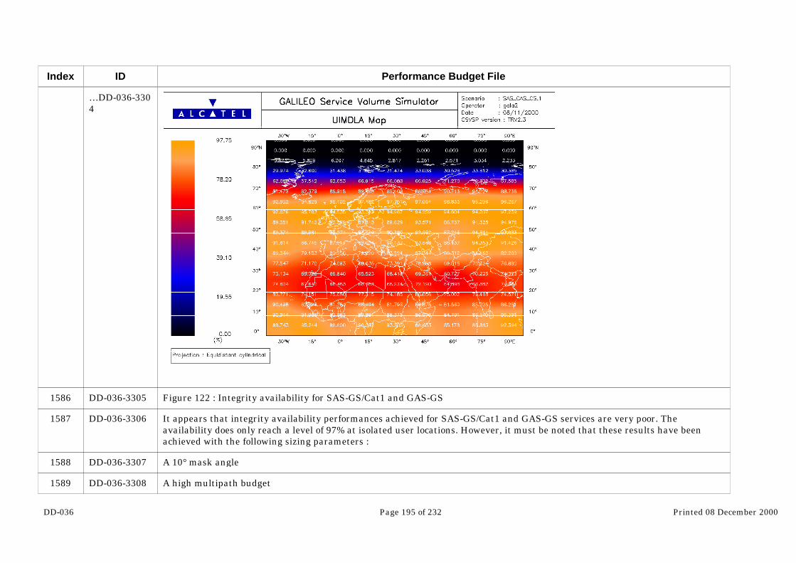
DD-036 Page 195 of 232 Printed 08 December 2000
Index
1586
1587
1588
1589
ID
…DD-036-3304
DD-036-3305
DD-036-3306
DD-036-3307
DD-036-3308
Performance Budget File
Figure 122 : Integrity availability for SAS-GS/Cat1 and GAS-GS
It appears that integrity availability performances achieved for SAS-GS/Cat1 and GAS-GS services are very poor. Theavailability does only reach a level of 97% at isolated user locations. However, it must be noted that these results have beenachieved with the following sizing parameters :
A 10° mask angle
A high multipath budget

DD-036 Page 196 of 232 Printed 08 December 2000
Index
1590
1591
1593
1594
1595
1596
1597
ID
DD-036-3309
DD-036-3310
DD-036-3315
DD-036-3316
DD-036-3317
DD-036-3318
DD-036-3319
Performance Budget File
Sensitivity of the SAS-GS/ Cat1 and GAS-GS performances to these sizing parameters will be studied in §7.1.2.2.4.
The following figures show the average protection levels (HPL and VPL) distributions in the case with no satellite failures.
Figure 123 : Average HPL distribution for SAS-GS/Cat1and GAS-GS
Figure 124 : Average VPL distribution for SAS-GS/Cat1and GAS-GS
From these figures, the margin between average HPL and the corresponding requirement seems correct (maximum value ofaverage HPL is 4.67m wrt a requirement of 8m) whereas the margin between average VPL and vertical alarm limit is negative :VAL value is overshot by some average VPL even when no satellite failures are introduced . Maximal average value reached isindeed 12.01m wrt a requirement of 10m and only 80% of the average VPL values are below this requirement. This explains thepoor availability observed on Figure 122.
7.1.2.2.4 SAS-RM
The definition of this service is nearly the same as for SAS-GS/Cat1, except that it is a regional service and it uses thegeostationary satellites of GNSS1, that is to say :
Inmarsat satellites (AOR-E, IOR, AOR-W, POR)
Artemis
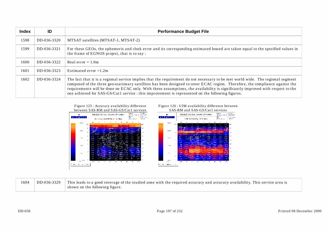
DD-036 Page 197 of 232 Printed 08 December 2000
Index
1598
1599
1600
1601
1602
1604
ID
DD-036-3320
DD-036-3321
DD-036-3322
DD-036-3323
DD-036-3324
DD-036-3329
Performance Budget File
MTSAT satellites (MTSAT-1, MTSAT-2)
For these GEOs, the ephemeris and clock error and its corresponding estimated bound are taken equal to the specified values inthe frame of EGNOS project, that is to say :
Real error = 1.0m
Estimated error =1.2m
The fact that it is a regional service implies that the requirement do not necessary to be met world wide. The regional segmentcomposed of the three geo-stationary satellites has been designed to cover ECAC region. Therefore, the compliance against therequirements will be done on ECAC only. With these assumptions, the availability is significantly improved with respect to theone achieved for SAS-GS/Cat1 service : this improvement is represented on the following figures.
Figure 125 : Accuracy availability differencebetween SAS-RM and SAS-GS/Cat1 services
Figure 126 : UIM availability difference betweenSAS-RM and SAS-GS/Cat1 services
This leads to a good coverage of the studied zone with the required accuracy and accuracy availability. This service area isshown on the following figure.
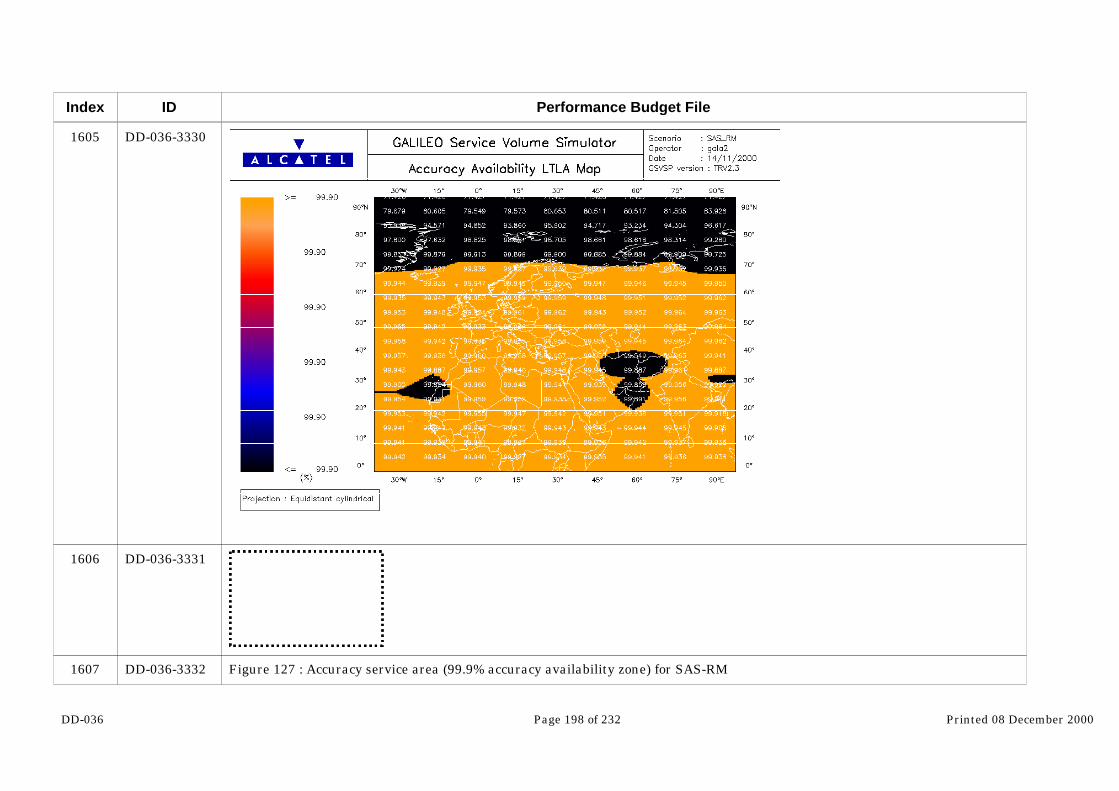
DD-036 Page 198 of 232 Printed 08 December 2000
Index
1605
1606
1607
ID
DD-036-3330
DD-036-3331
DD-036-3332
Performance Budget File
Figure 127 : Accuracy service area (99.9% accuracy availability zone) for SAS-RM

DD-036 Page 199 of 232 Printed 08 December 2000
Index
1608
1609
1610
ID
DD-036-3333
DD-036-3334
DD-036-3335
Performance Budget File
It can be concluded that accuracy availability performances achieved for SAS-RM are compliant with the requirement (99.9%)on the major part of the zone that covers the European region. The area above 65°N and some isolated locations below thislatitude are however not covered with the required availability.
Now, the improvement of UIM availability observed on Figure 126 leads to the following integrity availability map :

DD-036 Page 200 of 232 Printed 08 December 2000
Index
1611
1612
1613
1614
1615
1616
1617
1618
1619
1620
1621
1622
1623
ID
DD-036-3336
DD-036-3337
DD-036-3338
DD-036-3339
DD-036-3340
DD-036-3341
DD-036-3342
DD-036-3343
DD-036-3344
DD-036-3345
DD-036-3346
DD-036-3347
DD-036-3348
Performance Budget File
Figure 128 : Integrity availability for SAS-RM
It appears that integrity availability performances achieved for SAS-RM are well improved with respect to SAS-GS service butare still below the requirement (99.9%). The worst availability performances are obtained at latitudes above 70°N (availabilityfigures between 0% and 90%) and for a band located between 10°N and 40°N (availability between 87% and 97%). However, theavailability reaches a level of 99% on a significant part of the zone. On Europe, the service would be compliant for anavailability of 99%.
7.1.2.3 Sensitivity analysis of the availability for combined use of Galileo and GPS
As seen in the last paragraph, performances achieved by the combined use of GPS and Galileo are not fully compliant with therequirements specified for these services. So, in this part, different sensitivity analysis have been performed to assess theimpact of the change of different parameters. In particular, the following issues have been investigated :
Sensitivity to the multipath error budget
Sensitivity to the user mask angle
Sensitivity to the requirements
7.1.2.3.1 OAS-GS
For this service, only the sensitivity to the multipath budget and to the requirement have been analyzed.
7.1.2.3.1.1 Sensitivity to the multipath level
In §4, two UERE budgets are presented :
One taking into account pessimistic assumptions for multipath. This budget is the one that has been used to assess baselineperformances in the last paragraph.

DD-036 Page 201 of 232 Printed 08 December 2000
Index
1624
1625
1626
1627
ID
DD-036-3349
DD-036-3350
DD-036-3351
DD-036-3352
Performance Budget File
Another taking into account lower multipath environment. The results presented in the current paragraph correspond to thisbudget.
The following map represents the average accuracy availability obtained with this new assumption, all other simulationparameters being kept at the same values (baseline assumptions described in §6.1).
Figure 129 : OAS-GS accuracy availability for low multipath conditions

DD-036 Page 202 of 232 Printed 08 December 2000
Index
1628
1629
1630
1632
1633
1634
ID
DD-036-3353
DD-036-3354
DD-036-3355
DD-036-3360
DD-036-3361
DD-036-3362…
Performance Budget File
From this map, OAS-GS accuracy availability performances seem, with these multipath conditions, compliant with therequirements. The availability is indeed greater than 99.4% on the whole studied zone, with a significant part of the areacovered with an availability better than 99.6%.
7.1.2.3.1.2 Sensitivity to the requirement
An analysis of the causes of outages occurring in the nominal conditions (no satellite failures) has been made (cf. the followingfigures). It shows that all the outages correspond to HNSE overshooting the corresponding requirement.
Figure 130 : HNSE analysis during outages Figure 131 : VNSE analysis during outages
Indeed, it can be noticed that during outage periods, VNSE reaches at a maximum 7.25m (wrt a requirement of 10m) whereas,HNSE values are always above the corresponding requirement and are comprised between 4m and 4.73m.
Given this outage analysis, the horizontal accuracy requirement appears to be the driving factor for the accuracy availability.That is why, sensitivity analysis to this parameter is here presented : the following accuracy availability map corresponds to anhorizontal accuracy requirement of 6m, all other parameters being kept to their baseline values :

DD-036 Page 203 of 232 Printed 08 December 2000
Index
1635
1636
1637
ID
…DD-036-3362
DD-036-3363
DD-036-3364
DD-036-3365
Performance Budget File
Figure 132 : OAS-GS accuracy availability for HNSEreq=6m
It can be deduced that with an horizontal accuracy requirement of 6m, the accuracy availability is improved and is compliantwith the requirement (99%) on the whole zone. Moreover the main part of the zone benefits from availability figures above99.4%.
7.1.2.3.2 CAS1-GS

DD-036 Page 204 of 232 Printed 08 December 2000
Index
1638
1639
1640
1641
1642
1643
1644
ID
DD-036-3366
DD-036-3367
DD-036-3368
DD-036-3369
DD-036-3370
DD-036-3371
DD-036-3372…
Performance Budget File
For this service, only the sensitivity to the multipath budget and to the requirement have been analyzed.
7.1.2.3.2.1 Sensitivity to the multipath level
In §4, two UERE budgets are presented :
One taking into account pessimistic assumptions for multipath. This budget is the one that has been used to assess baselineperformances in the last paragraph.
Another taking into account lower multipath environment. The results presented in the current paragraph correspond to thisbudget.
The following map represents the average accuracy availability obtained with this new assumption, all other simulationparameters being kept at the same values (baseline assumptions described in §6.1).
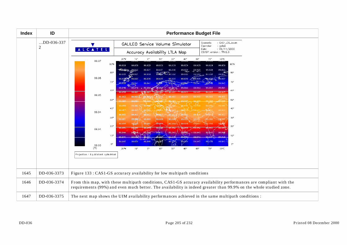
DD-036 Page 205 of 232 Printed 08 December 2000
Index
1645
1646
1647
ID
…DD-036-3372
DD-036-3373
DD-036-3374
DD-036-3375
Performance Budget File
Figure 133 : CAS1-GS accuracy availability for low multipath conditions
From this map, with these multipath conditions, CAS1-GS accuracy availability performances are compliant with therequirements (99%) and even much better. The availability is indeed greater than 99.9% on the whole studied zone.
The next map shows the UIM availability performances achieved in the same multipath conditions :

DD-036 Page 206 of 232 Printed 08 December 2000
Index
1648
1649
1650
1651
1652
ID
DD-036-3376
DD-036-3377
DD-036-3378
DD-036-3379
DD-036-3380
Performance Budget File
Figure 134 : CAS1-GS UIM availability for low multipath conditions
It can be concluded that with these multipath conditions, CAS1-GS UIM availability performances are also compliant with therequirements (99%) and even much better. The availability is indeed greater than 99.9% on the whole studied zone.
7.1.2.3.2.2 Sensitivity to the requirement
An analysis of the causes of outages occurring in the nominal conditions (no satellite failures) has been made (cf. the followingfigures). It shows that all the outages correspond to HNSE or HPL overshooting the corresponding requirements.

DD-036 Page 207 of 232 Printed 08 December 2000
Index
1655
ID
DD-036-3388
Performance Budget File
Figure 135 : HNSE analysis during accuracy outages Figure 136 : VNSE analysis during accuracy outages
Figure 137 : HPL analysis during integrity outages Figure 138 : VPL analysis during integrity outages
Indeed, it can be noticed that during outage periods, VNSE reaches at a maximum 6.94m (wrt a requirement of 10m) whereas,HNSE values are always above the corresponding requirement and are comprised between 4m and 4.71m. In the same way,VPL reaches at a maximum 18.65m (wrt a requirement of 32m) whereas, HPL values are always above the alarm limit and arecomprised between 13m and 13.55m. Finally, it can be noted also that the integrity outages occur much less frequently than theaccuracy ones.

DD-036 Page 208 of 232 Printed 08 December 2000
Index
1656
1657
1658
1659
ID
DD-036-3389
DD-036-3390
DD-036-3391
DD-036-3392
Performance Budget File
Given this outage analysis, the horizontal requirements appear to be the driving factors for the availability. That is why,sensitivity analysis to this parameter is here presented : the following availability maps corresponds to an horizontal accuracyrequirement of 5m and an HAL=14m, all other parameters being kept to their baseline values :
Figure 139 : CAS1-GS accuracy availability for HNSEreq=5m

DD-036 Page 209 of 232 Printed 08 December 2000
Index
1660
1661
1662
1663
ID
DD-036-3393
DD-036-3394
DD-036-3395
DD-036-3396
Performance Budget File
It can be deduced that with an horizontal accuracy requirement of 5m, the accuracy availability is improved and is compliantwith the requirement (99%) on the whole zone. Moreover the main part of the zone benefits from availability figures above99.4%.
Figure 140 : CAS1-GS integrity availability for HAL=14m
It can be deduced that with an horizontal alarm limit of 14m, the UIM availability is improved and is compliant with therequirement (99%) on the whole zone. Moreover the main part of the zone benefits from availability figures above 99.5%.
DD-036 Page 210 of 232 Printed 08 December 2000
Index
1664
1665
1666
1667
1668
1669
1670
1671
1672
1673
1674
ID
DD-036-3397
DD-036-3398
DD-036-3399
DD-036-3400
DD-036-3401
DD-036-3402
DD-036-3403
DD-036-3404
DD-036-3405
DD-036-3406
DD-036-3407…
Performance Budget File
7.1.2.3.3 SAS-GS and GAS-GS
For these services, given the poor availability achieved with the baseline parameters, only two changes have been analyzed :
One grouping the impacts of reducing both the multipath error budget and the user mask angle
Another assessing the sensitivity to requirements
7.1.2.3.3.1 Sensitivity to the multipath level and the user mask angle
In §4, two UERE budgets are presented :
One taking into account pessimistic assumptions for multipath. This budget is the one that has been used to assess baselineperformances in the last paragraph.
Another taking into account lower multipath environment. The results presented in the current paragraph correspond to thisbudget.
In addition, as for SAS and GAS users, the environment can be considered as open, the user mask angle has been reduced to 5°.
The following map represents the average accuracy availability obtained with this new assumptions (low multipath budget + 5°mask angle), all other simulation parameters being kept at the same values (baseline assumptions described in §6.1).

DD-036 Page 211 of 232 Printed 08 December 2000
Index
1675
1676
1677
ID
…DD-036-3407
DD-036-3408
DD-036-3409
DD-036-3410
Performance Budget File
Figure 141 : SAS-GS and GAS-GS accuracy availability for low multipath conditions and reduced user mask angle (5°)
It can be concluded that with these multipath conditions and a user mask angle of 5°, SAS-GS and GAS-GS accuracyavailability performances are greatly improved and are, on the main part of the zone, compliant with the requirements (99.9%).The main area not covered with the required availability is located above 65°N. Some other points located below 10°N do notmeet the requirement either.
The next map shows the UIM availability performances achieved in the same conditions :

DD-036 Page 212 of 232 Printed 08 December 2000
Index
1678
1679
1680
1681
ID
DD-036-3411
DD-036-3412
DD-036-3413
DD-036-3414
Performance Budget File
Figure 142 : SAS-GS and GAS-GS UIM availability for low multipath conditions and reduced user mask angle (5°)
From this map, it can be concluded that even with these multipath conditions and reduced mask angle, SAS-GS and GAS-GSUIM availability requirement is not met. The availability is however greatly improved wrt the baseline case (cf. Figure 122), insuch proportions that a level of 99% is achieved on a significant part of the studied zone.
7.1.2.3.3.2 Sensitivity to the requirement
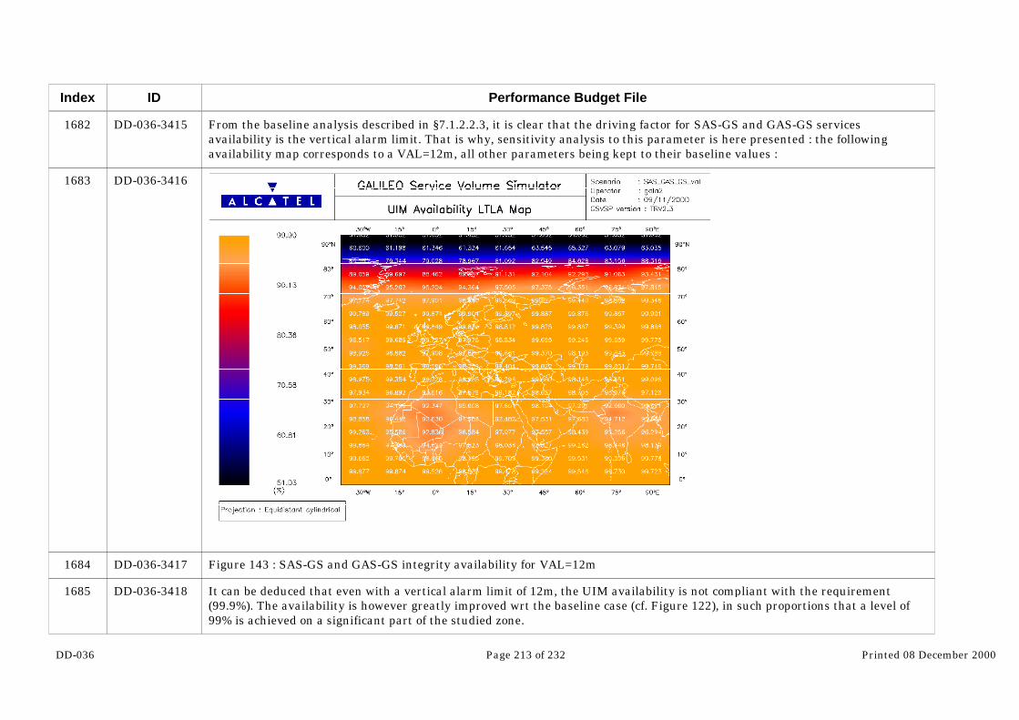
DD-036 Page 213 of 232 Printed 08 December 2000
Index
1682
1683
1684
1685
ID
DD-036-3415
DD-036-3416
DD-036-3417
DD-036-3418
Performance Budget File
From the baseline analysis described in §7.1.2.2.3, it is clear that the driving factor for SAS-GS and GAS-GS servicesavailability is the vertical alarm limit. That is why, sensitivity analysis to this parameter is here presented : the followingavailability map corresponds to a VAL=12m, all other parameters being kept to their baseline values :
Figure 143 : SAS-GS and GAS-GS integrity availability for VAL=12m
It can be deduced that even with a vertical alarm limit of 12m, the UIM availability is not compliant with the requirement(99.9%). The availability is however greatly improved wrt the baseline case (cf. Figure 122), in such proportions that a level of99% is achieved on a significant part of the studied zone.

DD-036 Page 214 of 232 Printed 08 December 2000
Index
1686
1687
1688
1689
1690
1691
1692
ID
DD-036-3419
DD-036-3420
DD-036-3421
DD-036-3422
DD-036-3423
DD-036-3424
DD-036-3425
Performance Budget File
7.2 Loran C/ Eurofix
7.2.1 Introduction
The radio-navigation system Loran C has got two features that may be appealing for integration with Galileo.
The first one is its robustness. Although the accuracy of the system does not match the one of satellite based navigationsystems, the integrity continuity and availability of the system have been already demonstrated. This is especially true instressed environment with high masking angle such as urban environment. L band signals cannot get through buildings orobstacles whereas low frequency signals such as the ones used by Loran C system can penetrate the buildings and provide apositioning in urban area with an acceptable availability.
One important drawback of Loran C is of course that it does not provide any navigation information in the vertical dimension. Therefore it is of little use for aviation application.
The second is its communication link capability. Loran C station could be used to broadcast on a long range the informationgenerated by a local differential station. Integrity information could be also transmitted through this communication link. Since integrity data flow increases significantly the bit rate of the system and consequently decreases the navigationperformance of Galileo, such alternative is worthy to investigate. This concept has been already exploited on GPS by the systemEurofix.
As far as performance estimation is concerned, the use of Eurofix concept is not different from the concept of local differential. Therefore, integration of Loran C communication link with Galileo will be simulated as such.
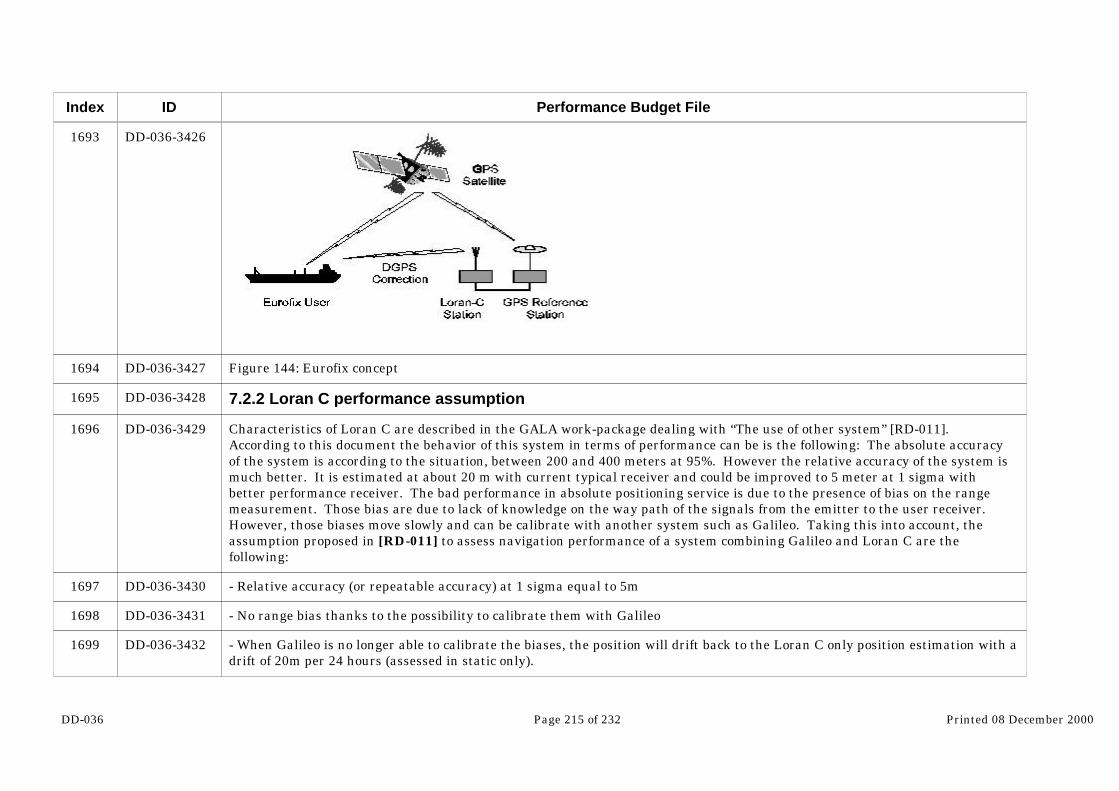
DD-036 Page 215 of 232 Printed 08 December 2000
Index
1693
1694
1695
1696
1697
1698
1699
ID
DD-036-3426
DD-036-3427
DD-036-3428
DD-036-3429
DD-036-3430
DD-036-3431
DD-036-3432
Performance Budget File
Figure 144: Eurofix concept
7.2.2 Loran C performance assumption
Characteristics of Loran C are described in the GALA work-package dealing with “The use of other system” [RD-011]. According to this document the behavior of this system in terms of performance can be is the following: The absolute accuracyof the system is according to the situation, between 200 and 400 meters at 95%. However the relative accuracy of the system ismuch better. It is estimated at about 20 m with current typical receiver and could be improved to 5 meter at 1 sigma withbetter performance receiver. The bad performance in absolute positioning service is due to the presence of bias on the rangemeasurement. Those bias are due to lack of knowledge on the way path of the signals from the emitter to the user receiver. However, those biases move slowly and can be calibrate with another system such as Galileo. Taking this into account, theassumption proposed in [RD-011] to assess navigation performance of a system combining Galileo and Loran C are thefollowing:
- Relative accuracy (or repeatable accuracy) at 1 sigma equal to 5m
- No range bias thanks to the possibility to calibrate them with Galileo
- When Galileo is no longer able to calibrate the biases, the position will drift back to the Loran C only position estimation with adrift of 20m per 24 hours (assessed in static only).

DD-036 Page 216 of 232 Printed 08 December 2000
Index
1700
1701
1702
1703
1704
1705
1706
1707
1708
1709
1710
1711
1712
ID
DD-036-3433
DD-036-3434
DD-036-3435
DD-036-3436
DD-036-3437
DD-036-3438
DD-036-3439
DD-036-3440
DD-036-3441
DD-036-3442
DD-036-3443
DD-036-3444
DD-036-3445
Performance Budget File
- The Loran C availability in urban environment is estimated at 90%
7.2.3 Combined Galileo/Loran C expected performance.
7.2.3.1 Performance Allocation
Performance of a combined Galileo + Loran C system appears very difficult to assess. Indeed as explained above the protocol touse Loran C with Galileo should be as follows:
- When Galileo is available the user position is computed with Galileo while Loran C biases are calibrated.
- When Galileo is not available, the user position is computed with Loran C.
The availability of the service will most likely not exceed the availability of Loran C (ie 90%). Indeed, in urban environment, theperformance of Galileo in terms of availability are very poor. In fact, an availability of 90% could be reached with a combinedsystem only if the availability of Galileo is high enough in order to calibrate Loran C sensors often enough.
The accuracy target for a Loran C + Galileo service is 15 meters at 95% in horizontal. This budget as first to be allocatedbetween Galileo and Loran C. Indeed, as soon as Galileo is no longer operational the accuracy of the position will degradeslowly. For instance, if the Galileo accuracy is required at 10 meters and the Loran C position drift with a rate of 20m per 24hours, Loran C could theoretically allow to provide a service of 15 meters accuracy for a period of 4.5 hours. Actually theallocation depends of the trade off between availability of Galileo and speed of divergence of Loran C.
If the Galileo availability was good in urban environment and the speed of divergence of Loran C high, most of the accuracybudget should be allocated to Loran C. On the contrary for a low accuracy of Galileo and a slow drift of Loran C, the main partof the budget should be allocated to Galileo. In order to preliminary assess the performance of a combined system the allocationof 10 meters on Galileo and 5 meters for Loran C.
7.2.3.2 Availability Performance in Urban canyon
As such statistics require extensive simulations, performances have been computed at a limited number of locations (5), (called“towns”) which have been selected because they offer a coverage of latitude from 0° to 80°.
The longitude selected is 0°. This is not restricting the validity of this study, as the selected MEO constellation provideshomogeneous performances with respect to longitude.
The selected user co-ordinates are
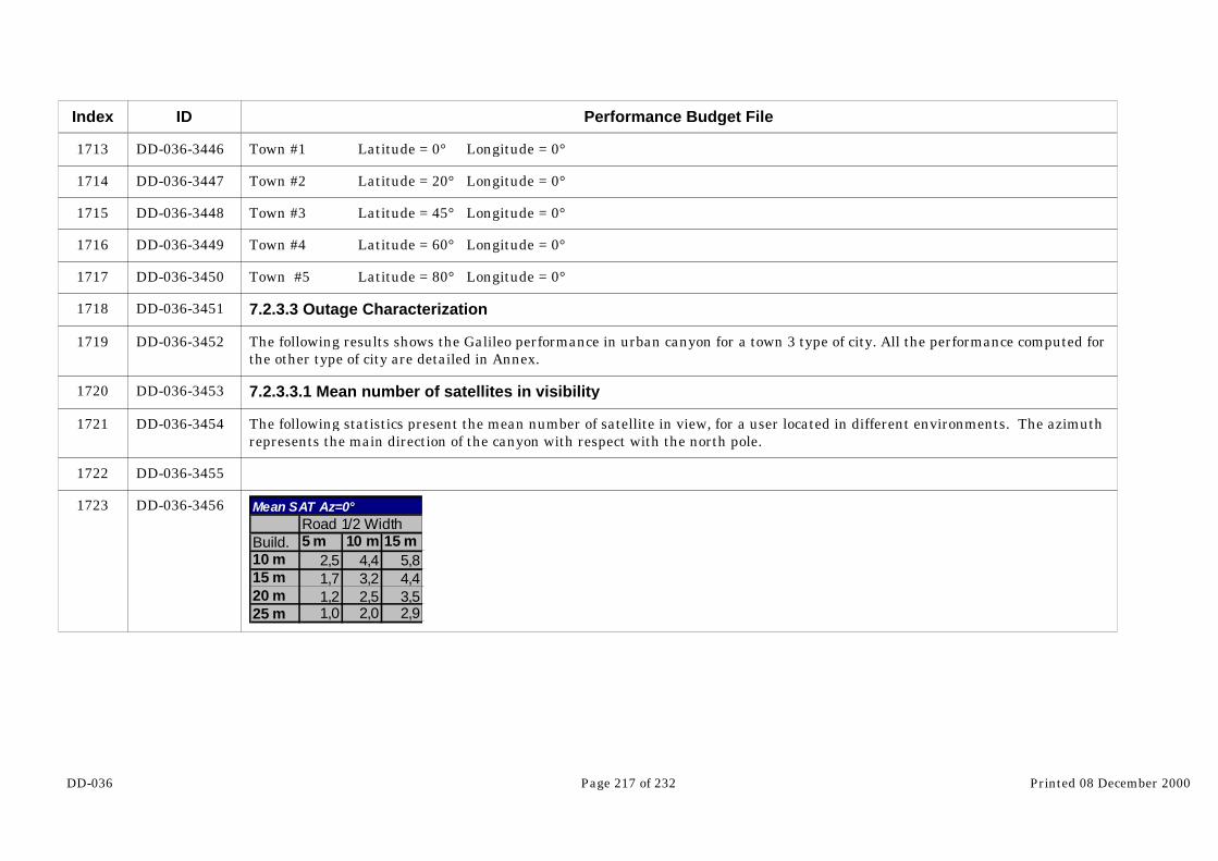
DD-036 Page 217 of 232 Printed 08 December 2000
Index
1713
1714
1715
1716
1717
1718
1719
1720
1721
1722
1723
ID
DD-036-3446
DD-036-3447
DD-036-3448
DD-036-3449
DD-036-3450
DD-036-3451
DD-036-3452
DD-036-3453
DD-036-3454
DD-036-3455
DD-036-3456
Performance Budget File
Town #1 Latitude = 0° Longitude = 0°
Town #2 Latitude = 20° Longitude = 0°
Town #3 Latitude = 45° Longitude = 0°
Town #4 Latitude = 60° Longitude = 0°
Town #5 Latitude = 80° Longitude = 0°
7.2.3.3 Outage Characterization
The following results shows the Galileo performance in urban canyon for a town 3 type of city. All the performance computed forthe other type of city are detailed in Annex.
7.2.3.3.1 Mean number of satellites in visibility
The following statistics present the mean number of satellite in view, for a user located in different environments. The azimuthrepresents the main direction of the canyon with respect with the north pole.
Mean SAT Az=0°Road 1/2 Width
Build. 5 m 10 m 15 m10 m 2,5 4,4 5,815 m 1,7 3,2 4,420 m 1,2 2,5 3,525 m 1,0 2,0 2,9

DD-036 Page 218 of 232 Printed 08 December 2000
Index
1724
1725
1726
1727
1728
ID
DD-036-3457
DD-036-3458
DD-036-3459
DD-036-3460
DD-036-3461…
Performance Budget File
Mean SAT Az=45°Road 1/2 Width
Build. 5 10 1510 m 3,5 5,7 6,415 m 2,6 4,5 5,420 m 2,0 3,8 4,625 m 1,7 3,3 4,0
Mean SAT Az=90°Road 1/2 Width
Build. 5 10 1510 3,8 5,7 6,715 2,9 4,5 5,720 2,1 3,8 4,825 1,6 3,3 4,3
Mean SAT- All AzRoad 1/2 Width
Build. 5 10 1510 3,3 5,2 6,315 2,4 4,1 5,120 1,8 3,4 4,325 1,4 2,8 3,7

DD-036 Page 219 of 232 Printed 08 December 2000
Index
1729
1730
1731
1732
ID
…DD-036-3461
DD-036-3462
DD-036-3463
DD-036-3464
DD-036-3465
Performance Budget File
5 m 10 m 15 mS1
S2
S3
S4
Distance to building
Building Heigh
Sat In visibility (Mean All Az. ) Town #1
6,0-8,0
4,0-6,0
2,0-4,0
0,0-2,0
Town 3
7.2.3.3.2 satellites availability
4 SAT Availability - Az=0°Road 1/2 Width
Build. 5 m 10 m 15 m10 m 4,0% 100,0% 100,0%15 m 0,0% 47,0% 100,0%20 m 0,0% 4,0% 59,0%25 m 0,0% 0,0% 29,0%
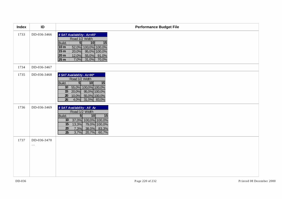
DD-036 Page 220 of 232 Printed 08 December 2000
Index
1733
1734
1735
1736
1737
ID
DD-036-3466
DD-036-3467
DD-036-3468
DD-036-3469
DD-036-3470…
Performance Budget File
4 SAT Availability - Az=45°Road 1/2 Width
Build. 5 10 1510 m 52,0% 100,0% 100,0%15 m 20,0% 95,0% 100,0%20 m 12,0% 55,0% 91,0%25 m 7,0% 31,0% 70,0%
4 SAT Availability - Az=90°Road 1/2 Width
Build. 5 10 1510 55,0% 100,0% 100,0%15 20,0% 95,0% 100,0%20 10,0% 55,0% 100,0%25 4,0% 31,0% 83,0%
4 SAT Availability - All AzRoad 1/2 Width
Build. 5 10 1510 37,0% 100,0% 100,0%15 13,3% 79,0% 100,0%20 7,3% 38,0% 83,3%25 3,7% 20,7% 60,7%

DD-036 Page 221 of 232 Printed 08 December 2000
Index
1738
1739
ID
…DD-036-3470
DD-036-3471
DD-036-3472…
Performance Budget File
5 m 10 m 15 m10
15
20
25
Distance to building
Building Heigh
4 SAT Availability (Mean) deg T3
80,0%-100,0%
60,0%-80,0%
40,0%-60,0%
20,0%-40,0%
0,0%-20,0%
7.2.3.3.3 Horizontal Accuracy availability statistics

DD-036 Page 222 of 232 Printed 08 December 2000
Index
1740
1741
1742
ID
…DD-036-3472
DD-036-3473
DD-036-3474
DD-036-3475
Performance Budget File
5 m 10 m 15 m10 m
15 m
20 m
25 m
Distance to Building
Building Heigh10m horizontal availability - Town #3
80,0%-100,0%
60,0%-80,0%
40,0%-60,0%
20,0%-40,0%
0,0%-20,0%
10 meters Availabili tyRoad 1/2 Width
Build. 5 m 10 m 15 m10 m 0,4% 61,0% 93,5%15 m 0,0% 12,2% 61,0%20 m 0,0% 0,4% 18,7%25 m 0,0% 0,0% 5,3%
7.2.3.4 Conclusion
As shown by the preceding simulations, the availability on Galileo in urban environment can vary a lot according to the kind ofcanyon considered. Although, according to the assumptions made on Loran C, a poor Galileo availability may allow to coastwith a combined receiver the bottom line for Galileo availability should not be below 20 or 10% at last. This condition is fulfilledin some of the canyon but not in all. However, taking into account that the user is supposed to be moving and therefore does notstay all the time in penalizing environment, the availability of Galileo appears sufficient to allow navigation in urban city whencombined with Loran C. However this conclusion has to be weighted with the following arguments:
DD-036 Page 223 of 232 Printed 08 December 2000
Index
1743
1744
1745
1746
1747
1748
ID
DD-036-3476
DD-036-3477
DD-036-3478
DD-036-3479
DD-036-3480
DD-036-3481
Performance Budget File
- The assumptions made on Loran C appear quite optimistic and shall be validated with measurement campaigns.
- The combination of Loran C and Galileo can allow radio navigation in “mean” urban environment. But there is always a limitto this combination. In the case that the environment is too stressed in terms of masking, Galileo may not be available at all.
Therefore, as a first estimation, the availability required for a Galileo/Loran C (15m at 90%) may be feasible. However,measurement campaign to better characterize urban environment and Loran C performance are mandatory to confirm thisassumption.
7.3 Hybridization with other system
Estimation of Galileo combined with other sensors such as inertial sensor and altimeter is something very difficult thatdemands the development of new tools as described in WP7.2. It is clear that users can take great benefit from other sensors. For instance, the mission requirements as they are expressed in [RD-01] are services with a 10 degrees elevation angle. It isclear urban users will navigate in much more stringent environment and that therefore, the performance detailed in themission requirements will be only achievable with the combination of Galileo with other sensors. Indeed, although the accuracyof those external sensors is less than Galileo or GPS, once calibrated they can allow to maintain navigation capability during acertain period of time when Galileo is not available. As explained in the Loran C performance estimation section, thecomplementarity between Galileo and the sensor considered depends on the outage duration and the sensor drift rate. For astatic user the outage periods are due to dynamic of the constellation. Therefore sensors with a slow drift is necessary. Fordynamic users, outage periods are due to dynamic of the user itself. Therefore they will be much shorter and more frequentwhich demands a sensor that can take advantage of the dynamic but that does not need to have a drift rate too slow.
In general, the performance detailed in the mission requirements relies on specific scenario in terms of masking angle,interference, multipath, user dynamic, ect… In more stringent conditions, a combination with other sensors will be necessary toreach performance equivalent to the mission requirements.

DD-036 Page 224 of 232 Printed 08 December 2000
Index
1749
1750
ID
DD-036-3482
DD-036-3483
Performance Budget File
8 Synthesis : Availability compliance matrix for GALILEO and Galileo+GPS services
The following table summarizes the outcomes of the last paragraphs, giving for each Galileo and Galileo+GPS service : itscompliance vs the requirements (C : compliant, PC : Partially Compliant, NC : Non Compliant) and if it is not compliant withbaseline assumptions, examples of compliance conditions (when investigated).
Service Compliance with availability requirements :
OAS-G1 C
OAS-G2 C
CAS1-G C
CAS1-L C
SAS-G/En route C
SAS-G/NPA C
SAS-G/Cat1 andGAS-G
PC for accuracy availability with baseline assumptions (cf. Figure82)NC for integrity availability with baseline assumptions (cf. Figure85)
Compliance conditions for UIM availability:
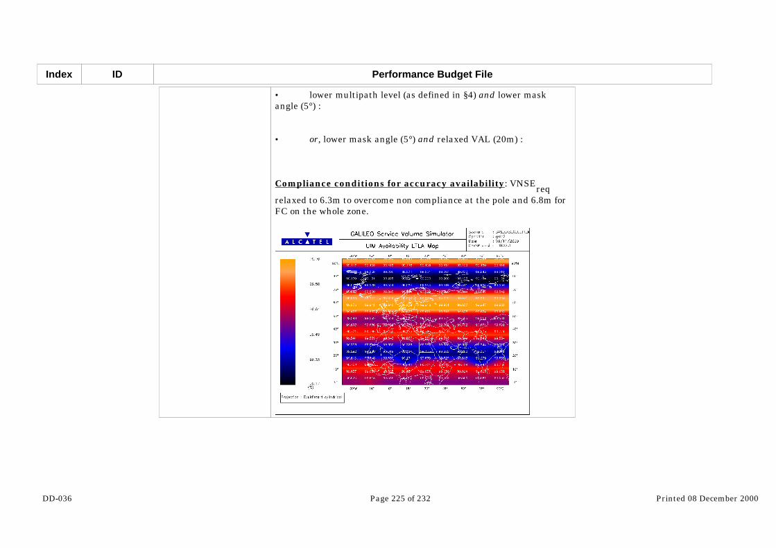
DD-036 Page 225 of 232 Printed 08 December 2000
Index ID Performance Budget File
• lower multipath level (as defined in §4) and lower maskangle (5°) :
• or, lower mask angle (5°) and relaxed VAL (20m) :
Compliance conditions for accuracy availability: VNSEreqrelaxed to 6.3m to overcome non compliance at the pole and 6.8m forFC on the whole zone.

DD-036 Page 226 of 232 Printed 08 December 2000
Index ID Performance Budget File
OAS-GS PC with baseline assumptionsFull Compliance conditions :• lower multipath error budget defined in §4 (cf. Figure 129) • or relaxed HNSE requirement (6m) (cf. Figure 132)
CAS1-GS PC with baseline assumptionsFull Compliance conditions :• lower multipath error budget of §4 (cf. Figure 133 andFigure 134) • or relaxed HNSE and HAL requirements (5m, 14m) (cf.Figure 139 and Figure 140)
SAS-GS/Cat1 andGAS-GS
NC with baseline assumptions (cf. Figure 119 and Figure 122) but :
• for accuracy, PC at 99% (FC at 99% except at high latitudeand for isolated points) • for accuracy, PC at 99.9% with low multipath of §4 and lowmasking (5°) • for Integrity, PC at 99% with 12 meters vertical alarm limit
SAS-RM C for accuracy availability with baseline assumptions NC for integrity availability with baseline assumptions
Compliance conditions :for integrity, PC at 99% with baseline assumptions (except onborder zone of ECAC) cf : Figure 128

DD-036 Page 227 of 232 Printed 08 December 2000
Index
1763
1764
1765
1766
1767
1768
1769
1770
ID
DD-036-3521
DD-036-3522
DD-036-3523
DD-036-3524
DD-036-3525
DD-036-3526
DD-036-3527
DD-036-3528
Performance Budget File
9 Conclusion And Open Points
9.1 Open points and recommendation
The goal of this document was to assess the feasibility of the Galileo mission performance requirements. Through, thisassessment several assumptions have been made. According to the situation those assumptions may have been verydimensioning on the performance results. Therefore they clearly need to be studied in more detail in order to solve the openpoints and consolidate the conclusions of this report. This section aims at pointing out those open issues and propose actions toclose them:
9.1.1 Local effects characterization
One main uncertainty in the performance estimation is the impact of the local effects on the accuracy, integrity, continuity andavailability of the system.
9.1.1.1 Multipath contribution in UERE budget
As explained in section 4 the UERE budget depends on several factors that are, satellite clock and ephemeris error, ionospheredelay, troposphere delay and receiver budget. Receiver budget includes multipath and interference effects. For most of theservice, Galileo users will apply dual frequency processing to cancel delay due to ionosphere. But this has the drawback toamplify all uncorrelated errors on each frequency. It means that when the receiver error is not negligible on one of the bothfrequency, it becomes the driving budget when dual frequency processing is used. Therefore, in order to be able to make areliable performance assessment, it is mandatory to characterize in more detail the error due to multipath. It is worth toremind that GPS is already broadcasting L band navigation signals. Therefore it would be strongly recommended to use thosesignals to characterize in detail the impact of multipath on pseudo-range measurements
9.1.1.2 Multiple and single failure due to local effects

DD-036 Page 228 of 232 Printed 08 December 2000
Index
1771
1772
1773
1774
1775
1776
1777
1778
ID
DD-036-3529
DD-036-3530
DD-036-3531
DD-036-3532
DD-036-3533
DD-036-3534
DD-036-3535
DD-036-3536
Performance Budget File
As explained 4.7.1.1, the strategy in this document has been to separate as far as possible the integrity processing functions thathandle failures due to satellite and failures due to local effects. Failures due to satellites are assumed handled by GIC whereasfailure due to local effects are handled by RAIM. The fault tree analysis has been derived, taking as assumption that theprobability of occurrence of failure due to local effect was 10-4/h. It goes without saying that this figure that is verydimensioning in the system design has to be further consolidated. This depends very much of the capacity of the receiver todetect and cancel local errors on pseudo-ranges. Indeed, putting a probability on this kind of phenomena is rather difficult. Thesolution is to design the receiver to be able to cope with this kind of effects and make them negligible at the end. If notnegligible, with a probability of occurrence low enough to be handle by RAIM or RAIM hybridized. Further study specifically onthis topic involving receiver manufacturers are clearly necessary if Galileo intends to provide an integrity service at user level.
9.1.1.3 Masking angle and Interference mask
In this document, assumption have been taken on masking angles and interference mask in order to assess system performance. Those assumptions may be reliable for some applications such as air navigation. However for applications in urbanenvironment those two parameters have two be further consolidated. In this case as well, a measurement campaign aiming atbetter characterizing user environment are clearly recommended. Galileo should take advantage that other systems like GPSand GLONASS are already available to assess the impact of user environment on the final system performance.
9.1.2 Allocation assumptions
9.1.2.1 RAMS analysis
All the requirements expressed in chapter 3 have been deducted from an a priori allocation. The idea was to allocate theperformance got from mission requirements to the system components. However, although this allocation has been done usingEGNOS experience on similar systems, this process needs now to get some feedback from the components on the requirementsthat have been put on them. Up to now the allocation have been made in open loop. It is therefore necessary to close loop withdifferent component designers in order to consolidate the requirements and re-allocate form one component to another ifnecessary. This has been initiated in GALA (space segment performance, receiver performance…) but needs to be furtheranalyzed in the next phase of the study
9.1.2.2 Clock stability
In this document, one driving assumption that has been made is to consider the Galileo satellite clocks as stable as the GPSones. Since Europe is currently working on the design and the development of such equipment this assumption may beoptimistic. Clocks stability can be considered as the key point of the system in terms of performance. It impacts:

DD-036 Page 229 of 232 Printed 08 December 2000
Index
1779
1780
1781
1782
1783
1784
1785
1786
1787
1788
1789
ID
DD-036-3537
DD-036-3538
DD-036-3539
DD-036-3540
DD-036-3541
DD-036-3542
DD-036-3543
DD-036-3544
DD-036-3545
DD-036-3546
DD-036-3547
Performance Budget File
- Accuracy through the clock contribution to UERE
- Integrity through the probability of occurrence of satellite failure
- Continuity and availability through the concept of SISA/IF
- Designing the system making too optimistic assumptions on this topic could jeopardize the whole project. Since Europe aslittle experience on this topic it is clearly recommended to be cautious on this specific point and to set up all back up solutionspossible in order to cope with potential clock non stability.
9.1.2.3 Network reliability
Through EGNOS experience, we are learning that one hard point to meet the final continuity requirements is the reliability ofthe network used for internal communication. It appears that small interruption called micro failure that last a few seconds are quite frequent. Therefore the system design has to be robust to this kind of event.
9.1.2.4 Up-link capabilities with dynamic antennas
One point of concern about the system performance is the up-link and down-link of the information trough the MEO’s. This is agreat modification comparing to the system already existing such as WAAS and EGNOS that broadcast the information throughstable geo stationary satellites. Broadcasting integrity information through the MEO’s as clear advantaged in terms of maskingangle for the users. However the feasibility of the concept has still to be proven. It means tracking dynamically a large numberof satellite with large antennas. May be more appropriate techniques like phase array antennas should be considered.
9.1.3 Integrity concept
9.1.3.1 Feasibility of the GIC concept
One assumption that has also been made in this document is to consider that the GIC integrity concept works. It means thatthe ground segment is able to detect and broadcast an alarm within the Time To Alarm in case of a failure on the spacesegment. This kind of statement should not be taken for granted. EGNOS is currently working on this problem and thesolutions are not that obvious. Many points are still under study such as the number of station really needed to monitor asatellite, the value of the SISA/UDRE that can be warranty by the ground segment, ect … Therefore stating that integrityworks because it has already be done in EGNOS is not recommended. A lot of efforts are still necessary on this topic to insurefinal integrity performance to the Galileo users.

DD-036 Page 230 of 232 Printed 08 December 2000
Index
1790
1791
1792
1793
1794
1795
1796
1797
1798
1799
1800
1801
1802
1803
ID
DD-036-3548
DD-036-3549
DD-036-3550
DD-036-3551
DD-036-3552
DD-036-3553
DD-036-3554
DD-036-3555
DD-036-3556
DD-036-3557
DD-036-3558
DD-036-3559
DD-036-3560
DD-036-3561
Performance Budget File
9.1.3.2 Integrity performance concept
The Galileo integrity concept relies on the broadcast of a parameter characterizing the signal in space accuracy (SISA) and thebroadcast of an alarm IF in the case that information due to SISA is incorrect. This choice has been made in order to optimizethe amount of data to broadcast to the users. But this relies on the fact that the clocks are assumed stable, then that the SISAparameter is quasi constant and does not need to be transmitted frequently. This option presents real advantages only if:
- The Galileo clocks are indeed stable
- Alarms does not need to be broadcast too often.
It is clear that if the alarm are broadcast in a regular basis, this option will degrade the continuity and availability on thesystem. Furthermore, flags will be sent to fulfill the most stringent requirements and may penalize other users that requiresless performance (NPA vs Cat 1).
Furthermore, as explained before in section 9.1.2.3, another weak point may be the network. The micro failures could resultfrequently in “satellite not monitored” situation. In the current baseline, an alarm is sent when a satellite becomes suddenly notmonitored. If this occurs frequently, alarms may overload the bandwidth available.
Therefore, although the baseline solution appears suited if the clocks are stable, it is recommended (as it is done in GALA) tokeep the possibility to broadcast SISA on more frequent basis as it is done for the SBAS UDRE.
9.1.4 Model limitations
9.1.4.1 Integrity modeling
As explained in the section 9.1.3.1, the GIC has been assumed meeting the right performance. This implies in terms of integrityavailability modeling two main assumptions:
- One satellite is considered monitored when seen by 4 monitoring stations
- The estimation error of the SISA value is considered equal at 30% of the clock and ephemeris value.
Those assumptions where made following EGNOS experience. However, even in EGNOS, those points are still under study. Therefore the result presented using those models have to be used with caution.
9.1.4.2 Availability modeling

DD-036 Page 231 of 232 Printed 08 December 2000
Index
1804
1805
1806
1807
1808
1809
1810
1811
1812
ID
DD-036-3562
DD-036-3563
DD-036-3564
DD-036-3565
DD-036-3566
DD-036-3567
DD-036-3568
DD-036-3569
DD-036-3570
Performance Budget File
The availability has been modeled in this document using the “mean availability” concept. This means that the availability isaveraged on the whole life of the system. Although it is already a good indicator it might not be enough to fully characterize thesystem performance at user level. In [RD-09], an update definition of the system availability has been proposed. Themotivation was to characterize the availability of the system in terms more meaningful to the users. This new definition willimply a different way to compute availability figures that will provide different results. This will have to be taken into accountin the definition of the Galileo performance mission requirements for next phases. Indeed, before requiring availability figuresthe first step is to clearly define what the users understand by availability.
9.1.4.3 Other sensor/ system simulation
One issue met in this document is the problem to simulate in a relevant way other system such as Loran C and other sensorssuch as inertial devices.
For Loran C, as explained in 7.2.3.4, the conclusion relies on assumption on Loran C performance. A measurement campaign isrecommended in order to back up those assumptions and characterize in more reliable way the performance that can beexpected from a combination of Galileo and Loran C.
For other sensors, as stated in chapter 7.3, development of adapted simulation tools is clearly necessary to go on with this kindof concept.
9.2 Conclusion
The goal of this document was to assess the feasibility of the Galileo mission performance requirements.
In order to do this the performance requirements have been first allocated to the different components of the system. Next thefeasibility of those requirements assuming that the system would follow the GALA baseline has been assessed. This has implieda detail computations of the UERE budget for each service.
The main conclusions of this performance assessment is the following. As detailed in the chapter 7, the performancerequirements are globally met for the different services. However for the service requiring Cat 1 capabilities the compliance canonly be partially stated. Indeed, although the 6 m vertical required with Galileo only appear achievable, the 15 m vertical alarmlimit required by civil aviation may rise some problems. Nevertheless this compliance attempt is strongly related withmultipath assumptions made. When low multipath is considered Cat 1 performance (15m vertical alarm limit) appearsachievable.

DD-036 Page 232 of 232 Printed 08 December 2000
Index
1813
1814
1815
ID
DD-036-3571
DD-036-3572
DD-036-3573
Performance Budget File
For services that will be provided with GPS the targeted performance were a 4 meters vertical accuracy and 10 meters verticalalarm limit with 99.9% availability. Although the result of the simulation has to taken with caution, even with GPS it appearsdifficult to reach this kind of performance. The performance reachable would closer to 4 meters vertical accuracy and 10 metersvertical alarm limit but with 99% availability.
Nevertheless, as detailed in the preceding chapter, the results provided in this document rely on many assumptions. Let usremind that the goal of this document was to assess the feasibility of the requirements. It does not pretend stating finalcompliance to the Galileo mission requirements. Before doing this, consolidation of the assumptions and feed back from thedifferent component designers is necessary. In particular, all the open points detailed in the preceding chapter need to beaddressed in more detail in order to be able to derive compliance statement with respect to performance.
END DOCUMENT


