31
Proposed Design Methodology for shotcrete W.C Joughin, G.C. Howell, A.R. Leach & J. Thompson
| Date post: | 31-Dec-2015 |
| Category: |
Documents |
| Upload: | melvin-terry |
| View: | 237 times |
| Download: | 0 times |

Proposed Design Methodology for shotcrete
W.C Joughin, G.C. Howell, A.R. Leach & J. Thompson

Research Workshop Team
William Joughin Graham Howell Tony Leach Jody Thompson Kevin Le Bron
Karl Akermann (AngloPlatinum), Lars Hage (BASF), Alan Naismith, Julian Venter, Dave Ortlepp

Design ProcessDetermination of rock
mass and loading conditions
•Rock mass classification•Stress modelling
Determination of Shotcrete Requirements
•Excavation requirements•Shotcrete function/purpose•Is it required?
Determination of Shotcrete Demand
•Deadweight loading•Quasi-static loading•Dynamic loading
Determination of Shotcrete Capacity
•Peak/Residual capacity•Energy absorption •Standard tests•Fibre content, mesh characteristics
Determination of safety factor

Rock mass conditions Q/GSI Stress
modelling
Low Stress Moderate stress High Stress DynamicLoading Condition
Mas
sive
(>70
)Jo
inte
d (4
0-70
)H
eavi
ly jo
inte
d (<
40)
Rock
Mas
s Co
nditi
on (
GSI
) Limited or no damage. Fracturing and minor spalling of rock occurs.
Intense fracturing, spalling and bulking of rock occurs.
Violent ejection of rock.
A1 A2 A3 A4
Blocks or wedges mobilize under gravity loading.
B1
Fracturing is altered by joint pattern. Blocks or wedges begin to slide.
B2
Intense fracturing and sliding along joints. Blocks or wedges slide.
B3
Violent ejection of rock.
B4
Unravelling of small blocks.
C1
Unravelling of small blocks. Failure can propagate into the rock mass if not controlled
C2 C3
Unravelling and crushing of blocks. Sliding along joints can create squeezing conditions
C4
Violent ejection of rock and unravelling

Shotcrete requirements(Excavation requirements)
Importance of excavation (access/production) Exposure of personnel Life of excavation Functional dimensions of excavation Maintenance and rehabilitation (redundancy)
Shotcrete requirements(Shotcrete function/purpose)
Structural support (Not covered) Fabric between tendons to contain
jointed/fractured rock To prevent spalling/strainbursting near face

Shotcrete requirements(is it required?)
Observations of block size and stress damage Keyblock analysis (eg Jblock) (joint controlled) Stress damage (RCF>0.7, 1/c ratio)
Empirical charts (joint controlled + SRF)
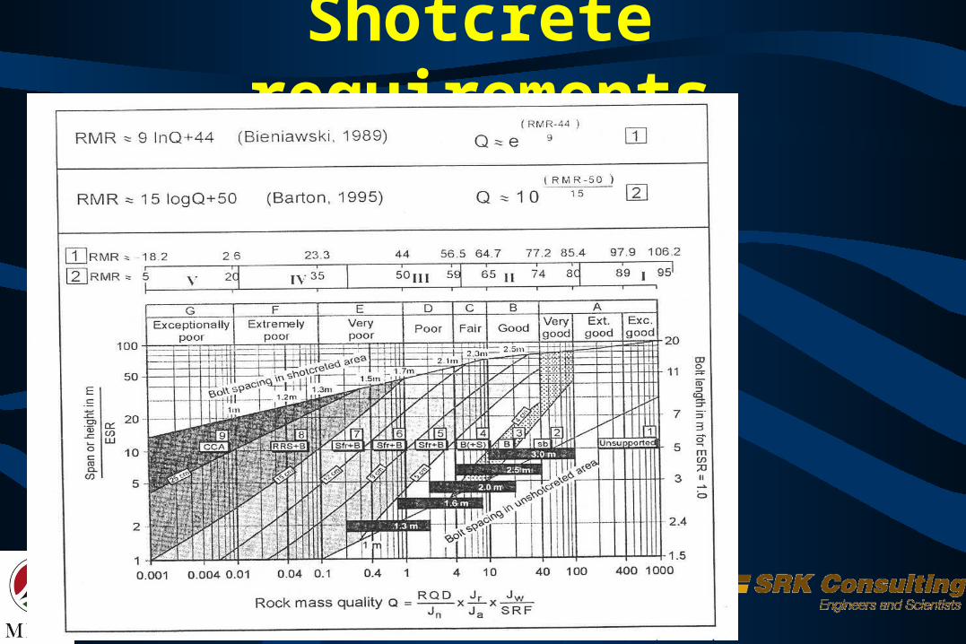
Shotcrete requirements
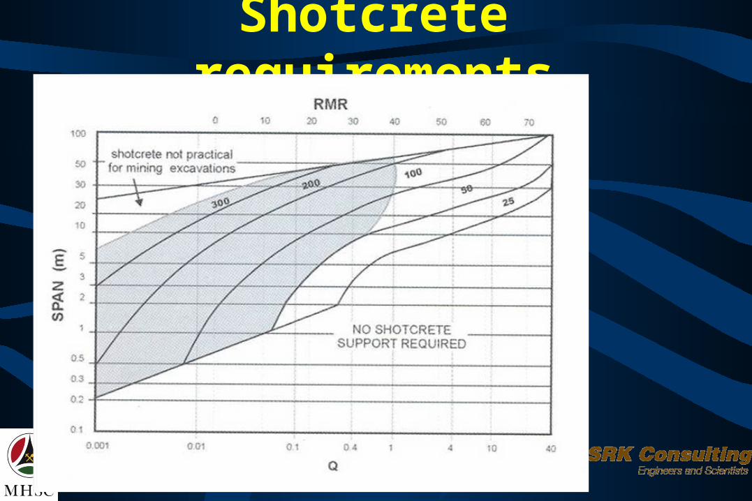
Shotcrete requirements
Shotcrete Demand Deadweight Quasi-static Dynamic

Shotcrete Demand (deadweight)
Roof prism (Barret & McCreath)
Sidewall prism slides Conservative estimate
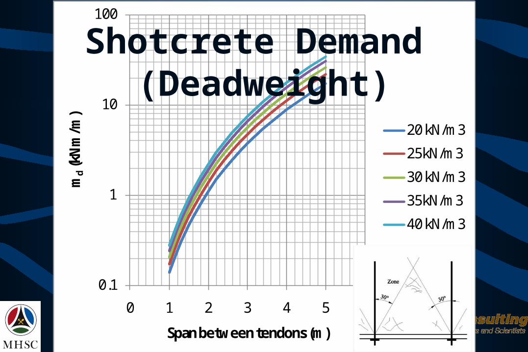
0.1
1
10
100
0 1 2 3 4 5 6
md
(kN
m/m
)
Span between tendons (m)
20 kN/m3
25kN/m3
30 kN/m3
35kN/m3
40 kN/m3
Shotcrete Demand (Deadweight)

Shotcrete Demand (quasi-static) Assumption: Rock mass will continue to deform
under quasi-static loading. Support pressures provided by shotcrete are inadequate to prevent deformation.
Objective is to survive the deformation and maintain the functions of containing the fractured rock mass
If the moment demand exceeds the peak moment capacity, the shotcrete will enter the residual state, providing it is reinforced.

Shotcrete Demand (quasi-static)(Displacement)
Displacement monitoring (extensometers) Maximum displacement from Udec GRC
modelling

0.E+00
1.E+05
2.E+05
3.E+05
4.E+05
5.E+05
6.E+05
7.E+05
8.E+05
9.E+05
1.E+06
0.00 5.00 10.00 15.00 20.00 25.00 30.00
Deformation (mm)
Su
pp
ort
Pre
ssu
re (
Pa
)
300 MPa
250 MPa
200 MPa
150 MPa
Displacement from modelling

Shotcrete Demand (quasi-static)(Displacement)
Quartzite150-200MPa 200-250MPa 250-300MPa
20 48.20 Squeezing Squeezing
30 5.50 Squeezing Squeezing
40 4.50 43.00 51.00
50 8.00 25.30 35.70
60 7.50 6.70 7.80
70 4.00 5.50 5.50
80 4.00 3.50 4.00
90 2.75 1.30 4.60
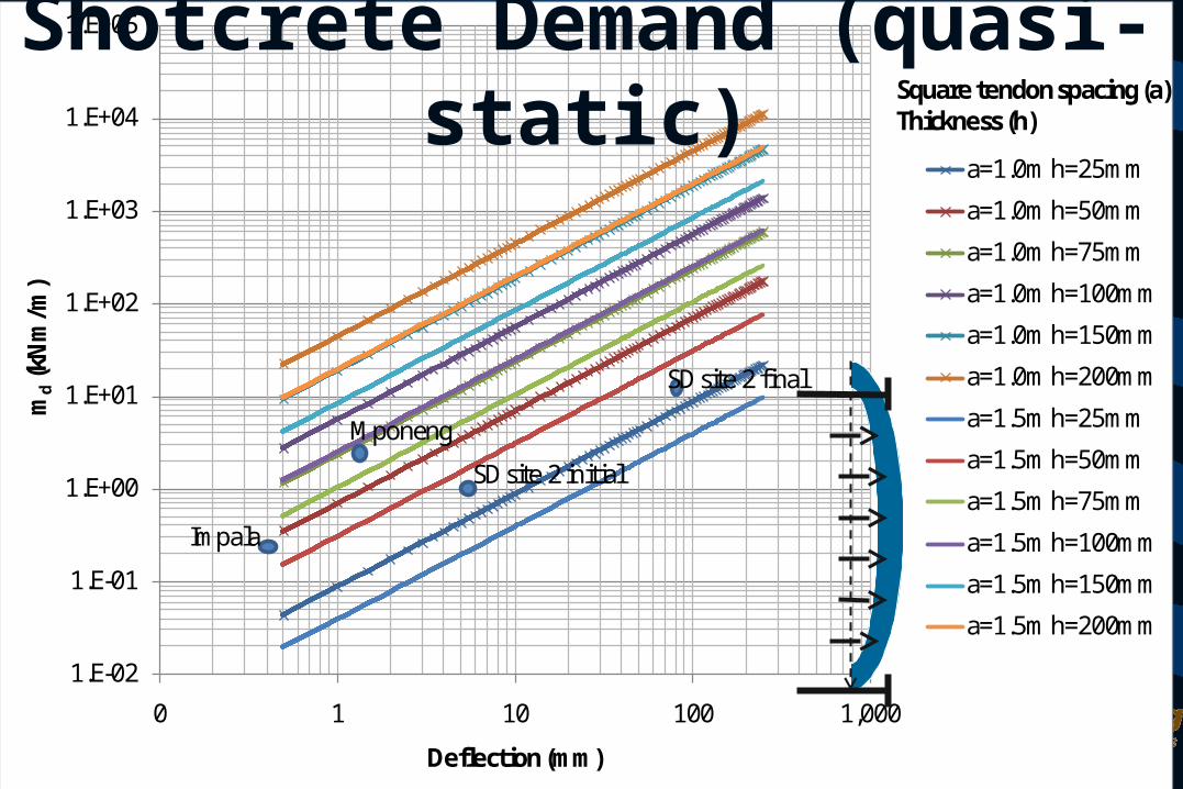
1.E-02
1.E-01
1.E+00
1.E+01
1.E+02
1.E+03
1.E+04
1.E+05
0 1 10 100 1,000
md
(kN
m/m
)
Deflection (mm)
a=1.0m h=25mm
a=1.0m h=50mm
a=1.0m h=75mm
a=1.0m h=100mm
a=1.0m h=150mm
a=1.0m h=200mm
a=1.5m h=25mm
a=1.5m h=50mm
a=1.5m h=75mm
a=1.5m h=100mm
a=1.5m h=150mm
a=1.5m h=200mm
Square tendon spacing (a)Thickness (h)
Impala
SD site 2 initial
SD site 2 final
Mponeng
Shotcrete Demand (quasi-static)
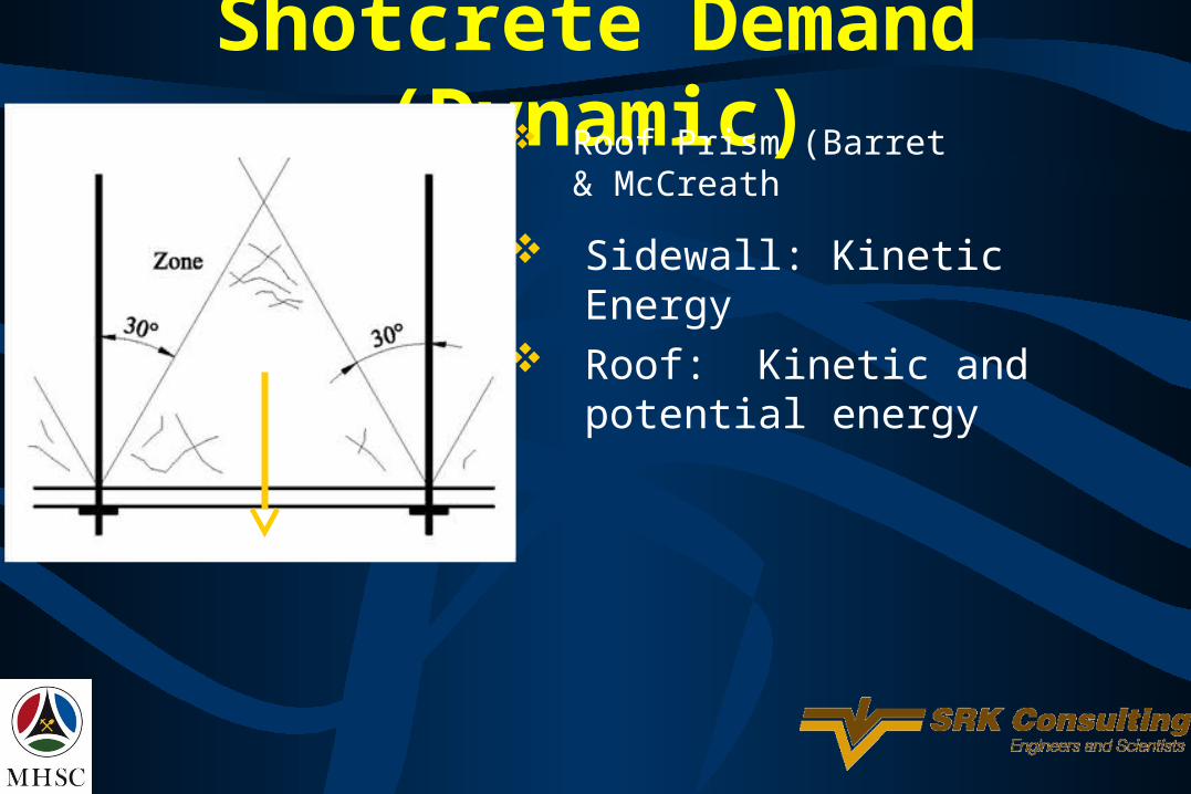
Shotcrete Demand (Dynamic) Roof Prism (Barret &
McCreath Sidewall: Kinetic Energy Roof: Kinetic and potential
energy

0.01
0.1
1
10
100
0.5 1 1.5 2 2.5 3 3.5
Kine
tic E
nerg
y (k
J)
Span between tendons (m)
0.2 m/s
0.5 m/s
1.0 m/s
1.5 m/s
2.0 m/s
2.5 m/s
3.0 m/sSouth Deep Blast PPV
South Deep Site effect
Mponeng Max PPV
Mponeng threshold PPV
Shotcrete Demand (Dynamic)

0.1
1
10
0.5 1 1.5 2 2.5 3 3.5
Pote
ntial
Ene
rgy
(kJ)
Span between tendons (m)
Shotcrete Demand (Dynamic)

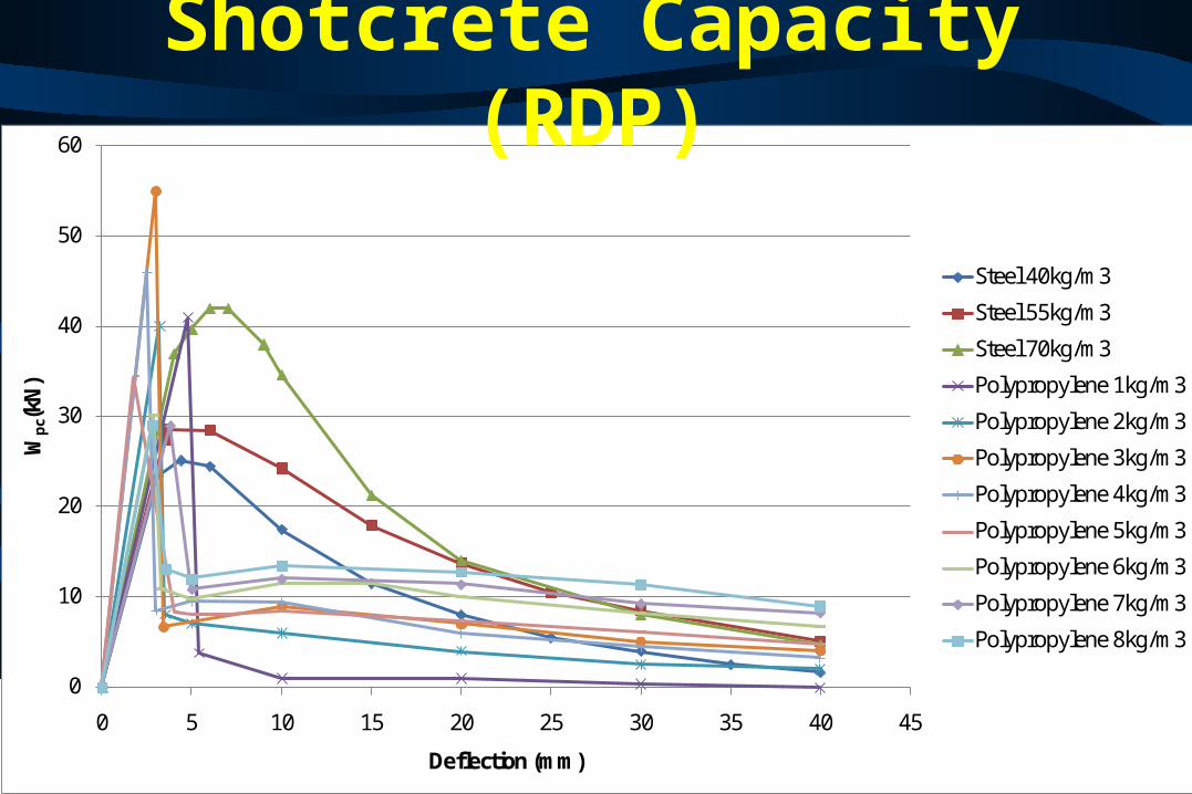
Shotcrete Capacity Peak/residual strength Energy Absorption Standard tests (RDP/ASTMC1550, EFNARC) Fibre content Mesh area

0
10
20
30
40
50
60
0 5 10 15 20 25 30 35 40 45
Wpc
(kN
)
Deflection (mm)
Steel 40kg/m3
Steel 55kg/m3
Steel 70kg/m3
Polypropylene 1kg/m3
Polypropylene 2kg/m3
Polypropylene 3kg/m3
Polypropylene 4kg/m3
Polypropylene 5kg/m3
Polypropylene 6kg/m3
Polypropylene 7kg/m3
Polypropylene 8kg/m3
Shotcrete Capacity (RDP)
Peak load

Shotcrete Capacity (RDP)
1.E-01
1.E+00
1.E+01
1.E+02
1.E+03
0 10 20 30 40 50 60
mc
(Nm
/m)
RDP Wpc (kN)
25mm
50mm
100mm
150mm
200mm
Thickness (h)
70kg/m3 steel fibre mix40kg/m3 steel fibre mix
55kg/m3 steel fibre mix1-8kg/m3 poly fibre mixes
Impala
South Deep site 2
Mponeng
0
10
20
30
40
50
60
0 5 10 15 20 25 30 35 40 45
Wpc
(kN
)
Deflection (mm)
Steel 40kg/m3
Steel 55kg/m3
Steel 70kg/m3
Polypropylene 1kg/m3
Polypropylene 2kg/m3
Polypropylene 3kg/m3
Polypropylene 4kg/m3
Polypropylene 5kg/m3
Polypropylene 6kg/m3
Polypropylene 7kg/m3
Polypropylene 8kg/m3
Shotcrete Capacity (RDP)

Shotcrete Capacity (RDP)
0.00
2.00
4.00
6.00
8.00
10.00
12.00
0.000 0.020 0.040 0.060 0.080 0.100 0.120
mpc
(kN
m/m
)
(radians)
Steel 40kg/m3
Steel 55kg/m3
Steel 70kg/m3
Polypropylene 1kg/m3
Polypropylene 2kg/m3
Polypropylene 3kg/m3
Polypropylene 4kg/m3
Polypropylene 5kg/m3
Polypropylene 6kg/m3
Polypropylene 7kg/m3
Polypropylene 8kg/m3
Genericδ
P (Load)Lever Arm = L/2
θ

0
50
100
150
200
250
300
350
400
0.00 10.00 20.00 30.00 40.00 50.00 60.00
Wc(
kN)
Deflection (mm)
Steel 40kg/m3
Steel 55kg/m3
Steel 70kg/m3
Shotcrete Capacity (on wall)
75mm thick, 1m tendon spacing8.66 x
1.33 x

0
1000
2000
3000
4000
5000
6000
7000
8000
9000
0.00 10.00 20.00 30.00 40.00 50.00 60.00
EAc(
J)
Deflection (mm)
Steel 40kg/m3
Steel 55kg/m3
Steel 70kg/m3
40 kg/m3 Panel
55 kg/m3 panel
70 kg/m3 panel
Shotcrete Capacity (on wall)75mm thick, 1m tendon spacing
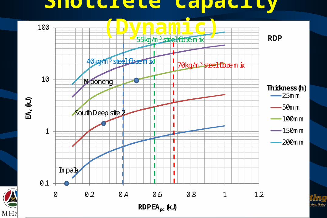
0.1
1
10
100
0 0.2 0.4 0.6 0.8 1 1.2
EAc(k
J)
RDP EApc (kJ)
25mm
50mm
100mm
150mm
200mm
Thickness (h)
70kg/m3 steel fibre mix40kg/m3 steel fibre mix
55kg/m3 steel fibre mix
Impala
South Deep site 2
Mponeng
Shotcrete capacity (Dynamic)RDP

Factor of safety
Loading South Deep Site
2
South Deep Site
2
Mponeng 116 level
Impala
Deadweight 2.4 2.4 72.1 4.6Quasi-static 1.0 0.1 9.3 2.6Dynamic Max 1.1 32.6Dynamic (3m/s) 0.1 0.9 0.08

Outstanding work Large scale panel tests (Kirsten & Labrum)
UDL & point loadThickness (50mm, 100mm, 150mm)Mesh & fibre
Large scale panel tests (Shotcrete working group – Gerhard Keyter)

Acknowledgements Mine Health and Safety Council (SIM040204) South Deep Gold Mine, Mponeng Mine, Impala 14# BASF (Lars Hage), Mash (Hector Snashall) Geopractica, University of the Witwatersrand Seismogen (Tony Ward) James Dube, Hlangabeza Gumede


