Eurographics Symposium on Parallel Graphics and Visualization (2010) J. Ahrens, K. Debattista, and R. Pajarola (Editors) Ray Tracing Dynamic Scenes with Shadows on the GPU Sashidhar Guntury and P J Narayanan Centre for Visual Information Processing International Institute of Information Technology (IIIT) Hyderabad India {sashidhar@research.,pjn@}iiit.ac.in Abstract We present fast ray tracing of dynamic scenes in this paper with primary and shadow rays. We present a GPU- friendly strategy to bring coherency to shadow rays, based on previous work on grids as acceleration structures. We introduce indirect mapping of threads to rays to improve the performance of ray tracing on the GPU for the traversal and intersection steps. We also construct a light frustum in a spherical space for shadow rays. A grid structure is constructed each frame for the light frustum and traversed coherently. This involves careful mapping of the primary ray information to the light space and balancing the work load of the threads. Using the finegrained parallelism of GPU, we reorder the shadow rays to make them coherent and process multiple thread blocks to each cell to balance the work load. Spherical mapping is key to handling light sources placed anywhere in the scene by reducing the triangle count and improving performance in shadow checking. In addition it also allows us to introduce spotlights in raytracing. In practice, we attain interactive performance for moderately large models which change dynamically in the scene. Categories and Subject Descriptors (according to ACM CCS): I.3.7 [Computer Graphics]: Three-Dimensional Graphics and Realism—Raytracing I.3.7 [Computer Graphics]: Three-Dimensional Graphics and Realism— Color, shading, shadowing, and texture I.3.6 [Computer Graphics]: Methodology and Techniques—Graphics data structures and data types I.3.1 [Computer Graphics]: Hardware Architecture—Graphics processors 1. Introduction Raytracing can produce images with very high degree of vi- sual realism, but at the expense much higher computation. Ray tracing consists of two tasks: building of the accelera- tion data structure and tracing of the rays. Tracing involves traversing the acceleration structure and primitive intersec- tion. Fast raytracing on the GPU is receiving a lot of in- terest in recent times, given their high compute power. Ray tracing dynamic and deformable scenes is now possible at near-interactive rates on modern GPUs. Acceleration data structures play a central role in ray tracing. A uniform grid is perhaps the simplest data structure used for ray tracing. Bounding Volume Hierarchies (BVH) [WBS07, LeYM06] and KD-trees [PGSS07, SSK07] have also been used widely for raytracing. BVH and kd-trees can exploit ray coherence more efficiently than grids. Their hierarchy also helps elim- inate large portions of primitives before actual intersection. Grids are easiest to build, giving them an edge over other structures for scenes where acceleration structure has to be built frequently. The cost of building a kd-tree or a BVH is significantly higher. Ray specialized grids like a perspec- tive grid take advantage of the common point of origin of the rays and have a high degree of coherence. This makes ray traversal efficient and fast. Primary rays are examples of highly coherent rays. They originate from the camera point and their traversal is always bounded by a frustum. Patidar and Narayanan demonstrated the utility of such grids for pri- mary rays [PN08] for deformable models by sorting trian- gles to perspective cells in each frame. The grid construction took only 15-30% of the total time for them. The ray tracing step dominates the total running time as a result. In this paper, we examine the performance of grids for raytracing dynamic scenes for both primary as well as shadow rays. We show the use of perspective grids for the primary as well as shadow rays. We reduce the problem of shadow rays to another round of spherical grid construction c The Eurographics Association 2010.
Transcript
Eurographics Symposium on Parallel Graphics and Visualization (2010)J. Ahrens, K. Debattista, and R. Pajarola (Editors)
Ray Tracing Dynamic Scenes with Shadows on the GPU
Sashidhar Guntury and P J Narayanan
Centre for Visual Information ProcessingInternational Institute of Information Technology (IIIT)
We present fast ray tracing of dynamic scenes in this paper with primary and shadow rays. We present a GPU-
friendly strategy to bring coherency to shadow rays, based on previous work on grids as acceleration structures.
We introduce indirect mapping of threads to rays to improve the performance of ray tracing on the GPU for the
traversal and intersection steps. We also construct a light frustum in a spherical space for shadow rays. A grid
structure is constructed each frame for the light frustum and traversed coherently. This involves careful mapping of
the primary ray information to the light space and balancing the work load of the threads. Using the finegrained
parallelism of GPU, we reorder the shadow rays to make them coherent and process multiple thread blocks to
each cell to balance the work load. Spherical mapping is key to handling light sources placed anywhere in the
scene by reducing the triangle count and improving performance in shadow checking. In addition it also allows us
to introduce spotlights in raytracing. In practice, we attain interactive performance for moderately large models
which change dynamically in the scene.
Categories and Subject Descriptors (according to ACM CCS): I.3.7 [Computer Graphics]: Three-DimensionalGraphics and Realism—Raytracing I.3.7 [Computer Graphics]: Three-Dimensional Graphics and Realism—Color, shading, shadowing, and texture I.3.6 [Computer Graphics]: Methodology and Techniques—Graphics datastructures and data types I.3.1 [Computer Graphics]: Hardware Architecture—Graphics processors
1. Introduction
Raytracing can produce images with very high degree of vi-sual realism, but at the expense much higher computation.Ray tracing consists of two tasks: building of the accelera-tion data structure and tracing of the rays. Tracing involvestraversing the acceleration structure and primitive intersec-tion. Fast raytracing on the GPU is receiving a lot of in-terest in recent times, given their high compute power. Raytracing dynamic and deformable scenes is now possible atnear-interactive rates on modern GPUs. Acceleration datastructures play a central role in ray tracing. A uniform gridis perhaps the simplest data structure used for ray tracing.Bounding Volume Hierarchies (BVH) [WBS07, LeYM06]and KD-trees [PGSS07,SSK07] have also been used widelyfor raytracing. BVH and kd-trees can exploit ray coherencemore efficiently than grids. Their hierarchy also helps elim-inate large portions of primitives before actual intersection.
Grids are easiest to build, giving them an edge over other
structures for scenes where acceleration structure has to bebuilt frequently. The cost of building a kd-tree or a BVHis significantly higher. Ray specialized grids like a perspec-tive grid take advantage of the common point of origin ofthe rays and have a high degree of coherence. This makesray traversal efficient and fast. Primary rays are examples ofhighly coherent rays. They originate from the camera pointand their traversal is always bounded by a frustum. Patidarand Narayanan demonstrated the utility of such grids for pri-mary rays [PN08] for deformable models by sorting trian-gles to perspective cells in each frame. The grid constructiontook only 15-30% of the total time for them. The ray tracingstep dominates the total running time as a result.
In this paper, we examine the performance of grids forraytracing dynamic scenes for both primary as well asshadow rays. We show the use of perspective grids for theprimary as well as shadow rays. We reduce the problem ofshadow rays to another round of spherical grid construction
Sashidhar Guntury & P J Narayanan / Ray Tracing Dynamic Scenes with Shadows on the GPU
and tracing from the point of view of the light source. Theshadow rays are traced exactly to provide correct shadows.We build the perspective grid for each light in a sphericalspace. This enables us to place the lights anywhere inside oroutside the scene and also provide spotlight effects. We areable to construct and render fairy forest model with a mov-ing light in about 80 ms and the Conference hall model withone light in about 62 ms.
2. Background and Previous Work
A survey of the current techniques for ray tracing can befound in [WMG∗07]. Acceleration data structures are builtto speed up the process of finding ray triangle intersection.Earlier, the entire process of raytracing was offline and thetime to build the datastructure was relatively small. Multi-core CPUs and GPUs, make raytracing is possible at inter-active rates [RSH05], with the data structure building be-ing the bottleneck, especially on dynamic scenes. Consider-able work has gone into speeding up this process, especiallyon parallelizing the build on GPUs. Zhou et al. [ZHWG08]and Lauterbach et al. [LGS∗09] gave fast methods of con-structing kd-trees and BVH respectively on GPU. Patidarand Narayanan built a perspective grid in parallel on theGPU [PN08]. The main drawback of their approach was thatof triangles distributions and spanning arbitrary number ofvoxels. It was solved by Kalojanov and Slusallek on uniformgrids [KS09]. They also used appropriate grid resolution toimprove the quality of the grid.
Unlike on a BVH and a kd-tree, rays on grids can not behandled as packets easily. Wald et al. [WIK∗06] presentedan algorithm for traversing the grid in a slice-wise coher-ent manner. Due to the use of a frustum like grid, Hunt andMark [HM08] and Patidar and Narayanan [PN08] treat thecamera rays in a totally coherent manner, making traversalefficient. Hunt and Mark suggested the idea of rebuildingthe data structure from the light point of view on a multicoreCPU [HM08]. Our technique of building a DS from lightpoint of view is similar to theirs but goes much further bybuilding a spherical grid to increase efficiency as well as tosupport spotlights and lights within the scene.
2.1. GPU Computing Model
We implement our techniques using the CUDA [NBGS08]programming model on Nvidia GPUs. CUDA uses kernels,which are programs that run in parallel on all threads. Ahuge number of threads – upwards of tens of thousands – islaunched for efficiency. The threads are grouped into thread-blocks or CUDA blocks. Threads within a single CUDAblock can be synchronized with negligible overhead. Theyalso have access to a small, fast, on-chip shared memory.Global memory is accessible to all threads, but is consider-ably slower.
Threads are batched into warps (of 32 threads), which run
in a strictly SIMD mode. Warps are scheduled sequentiallyon available processor resources. Thus, the SIMD width ofthe GPU computing model is the size of the warp. Memoryaccess patterns of threads of a warp also affect performancedeeply. Memory performance is best if proximate threads ac-cess global memory locations that are close. Performance isbest if data used by all threads of a block is loaded onto theshared memory.
3. Perspective Grids for Ray Tracing
Y
X
Z
Figure 1: The triangle storage layout. This kind of layout is
achieved by keeping the X value in the MSB and Z extent in
the LSB.
We construct a perspective grid by dividing the view frus-tum into voxels. This scheme is very similar to [PN08,HM08]. Similar to [KS09] we determine the cells each tri-angle spans and build a list of triangles for each cell. Thisprocedure is less sensitive to the triangle distribution in thescene. We create a list of (triangle, cell number) pairs, withone entry for each cell that each triangle maps to. We alsocan remove back-facing triangles to reduce the number ofentries in the list. This leads to a faster build of the grid andfewer triangles to be checked during ray traversal. Since thenumber of cells is in the range of 8K to 1M, we use the scal-able SplitSort [PN09] to sort this list with the cell-id as thekey. We use scan primitives to build the list of triangles ineach cell.
The perspective grid provides perfect coherence to pri-mary rays. We process the rays of each tile together on theGPU using a CUDA block or a work group, with each pixelassigned to a thread or a work item. The triangle data isbrought into the shared memory before intersection calcu-lations. Since all threads need to process all triangles in thecell, the overhead of bringing the triangles is amortized overthe intersections. The threads alternate between loading aportion of the triangles into shared memory and computingintersections for them, with a synchronization between thesetwo roles. A thread that has found an intersection at one cellneed not check for intersection in a later cell, as the cellsare processed in a front-to-back order. We use the optimizedroutine for checking triangle intersection [MT05].
Sashidhar Guntury & P J Narayanan / Ray Tracing Dynamic Scenes with Shadows on the GPU
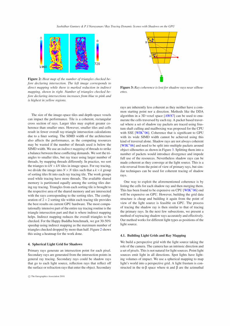
Figure 2: Heat map of the number of triangles checked be-
fore declaring intersection. The left image corresponds to
direct mapping while there is marked reduction in indirect
mapping, shown in right. Number of triangles checked be-
fore declaring intersections increases from blue to pink and
is highest in yellow regions.
The size of the image-space tiles and depth-space voxelscan impact the performance. Tile is a coherent, rectangularcross section of rays. Larger tiles may exploit greater co-herence than smaller ones. However, smaller tiles and cellsresult in fewer overall ray-triangle intersection calculationsdue to a finer sorting. The SIMD width of the architecturealso affects the performance, as the computing resourcesmay be wasted if the number of threads used is below theSIMDwidth. We use an indirect mapping of threads to strikea balance between these conflicting demands. We sort the tri-angles to smaller tiles, but ray trace using larger number ofthreads, by mapping threads differently. In practice, we sortthe trianges to kN×kN tiles in image space. For ray tracing,we divide the image into N×N tiles such that a k× k groupof sorting tiles fit into each ray tracing tile. The work groupsused while tracing have more threads. The available sharedmemory is partitioned equally among the sorting tiles dur-ing ray tracing. Triangles from each sorting tile is brought tothe respective area of the shared memory and are intersectedwith the rays corresponding to the sorting tiles. The config-uration of 2×2 sorting tile within each tracing tile providesthe best results on current GPU hardware. The most compu-tationally intensive part of the entire ray tracing routine is thetriangle intersection part and that is where indirect mappinghelps. Indirect mapping reduces the overall triangles to bechecked. For the Happy Buddha benchmark, we got 30-50%speedup using indirect mapping as the maximum number oftriangles checked dropped by more than half. Figure 2 showsthis using a heatmap for the work done.
4. Spherical Light Grid for Shadows
Primary rays generate an intersection point for each pixel.Secondary rays are generated from the intersection points ingeneral ray tracing. Secondary rays could be shadow raysthat go to each light source, reflection rays that reflect offthe surface or refraction rays that enter the object. Secondary
B
A
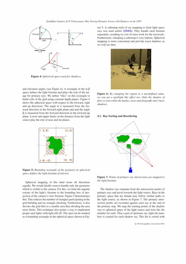
Figure 3: Ray coherence is lost for shadow rays near silhou-
ettes.
rays are inherently less coherent as they neither have a com-mon starting point nor a direction. Methods like the DDAalgorithm in a 3D voxel space [AW87] can be used to enu-merate the cells traversed by each ray. A packet based traver-sal where a set of shadow ray packets are traced using frus-tum shaft culling and mailboxing was proposed for the CPUwith SSE [WIK∗06]. Coherence that is significant to GPUwith its wide SIMD width cannot be achieved using thiskind of traversal alone. Shadow rays are not always coherent[WIK∗06] and need to be split into multiple packets aroundobject silhouettes as shown in Figure 3. Splitting them into anumber of packets would introduce divergence and impedefull use of the resources. Nevertheless shadow rays can bemade coherent as they converge at the light source. This is arole reversal from the point of view of primary rays, but sim-ilar techniques can be used for coherent tracing of shadowrays.
One way to exploit the aforementioned coherence is bylisting the cells for each shadow ray and then merging them.This has been found to be expensive on CPU [WIK∗06] ondwill be expensive on GPU. However, building the grid datastructure is cheap and building it again from the point ofview of the light source is feasible on GPU. The processof tracing the shadow ray is then similar to that of tracingthe primary rays. In the next few subsections, we present amethod of raytracing shadow rays accurately and effectively.Our method works for different light types as positions of thelight source.
4.1. Building Light Grids and Ray Mapping
We build a perspective grid with the light source taking therole of the camera. The camera has an intrinsic direction anda set of pixels. This is not natural for light sources. Point lightsources emit light in all directions. Spot lights have light-ing volumes of impact. We use a spherical mapping to maplight’s world into a perspective grid. A light frustum is con-structed in the α-β space where α and β are the azimuthal
Sashidhar Guntury & P J Narayanan / Ray Tracing Dynamic Scenes with Shadows on the GPU
up
forwardrightα
β
forward
right
α A B
C
α
π
A B
C
C
Figure 4: Spherical space used for shadows.
and elevation angles (see Figure 4). A rectangle in the α-βspace defines the light frustum and plays the role of the im-age for primary rays. We define “tiles” on this rectangle tobuild cells of the grid using constant depth planes. Figure 4shows the spherical space with respect to the forward, rightand up directions. The angle α is measured from the for-ward direction in the forward-right plane and and the angleβ is measured from the forward direction in the forward-upplane. Lower and upper limits on the distance from the lightsource play the role of near and far planes.
Figure 5: Bounding rectangle of the geometry in spherical
space defines the light frustum of interest.
Spherical mapping of this kind treats all directionsequally. We would ideally want to handle only the geometrywhich is visible to the camera. For this, we limit the angularextents of the light’s frustum to the bounding box of pro-jection of the camera’s view frustum. Figure 5 demonstratesthis. This reduces the number of triangles participating in thegrid building and ray triangle checking. Furthermore, it alsodevotes the grid tiles to a smaller area thus dividing the areamore finely. This technique also points a way to implementproper spot lights with light fall off. The spot can be markedas a bounding rectangle in the spherical space shown in Fig-
ure 5. A cubemap style of ray mapping to limit light spacerays was used earlier [HM08]. They handle each frustumseparately, resulting in a lot of extra work for the traversals.Furthermore, clamping a cubemap is very tedious. Sphericalmapping is more convenient and provide exact shadows aswe will see later.
Figure 6: By clamping the region to a userdefined value,
we can get a spotlight like effect too. Only the shadow of
fairy is seen while the bushes, trees and dragonfly don’t have
shadows.
4.2. Ray Sorting and Reordering
Figure 7: Points of primary ray intersection are mapped to
the light frustum.
The shadow rays emanate from the intersection points ofprimary rays and travel towards the light source. Rays in theprimary space that are distant may follow similar paths tothe light source, as shown in Figure 7. The primary inter-section points are recorded against each ray at the end ofthe primary step. We map the starting points of the shadowrays to spherical space of the light source and store the tilenumber for each. Thus a pair of (primary ray, light tile num-ber) is created for each shadow ray. This list is sorted with
Sashidhar Guntury & P J Narayanan / Ray Tracing Dynamic Scenes with Shadows on the GPU
the tile number as the key to bring shadow rays that belongto the light tile together. This brings similar coherence tosecondary rays as the primary ones, with the informationabout each shadow ray that passes through the tile available.Shadow ray generation and reordering are performed on theGPU in parallel using scan primitives [SHZO07] from theCUDPP library and the SplitSort primitive, which can han-dle arbitrary length keys [PN09].
4.3. Load Balancing
For tracing primary rays, blocks of threads are assigned totiles directly or indirectly. This is efficient for them as thenumber of rays in each tile is a constant. For shadow rays,however, the number per tile can vary widely. The abovethread mapping strategy can be inefficient due to the im-balance in work loads. We try to keep the number of rayshandled by each thread block below a maximum value. Thisneeds assigning multiple thread blocks to excessively popu-lated light tiles. We do this by splitting tiles with more than amaximum number of shadow rays into multiple logical tiles.Sparsely populated tiles, however, cannot be merged as theywork on different triangle data.
Suppose a light tile has R > r rays mapping to it, where ris the number that a thread block can handle efficiently. Weassign ⌈R/r⌉ blocks in the CUDA program to this tile. Othertiles are mapped to one thread block each, after eliminatingempty ones. The total number of thread blocks needed is
Ctotal =N
∑j=1⌈R j/r⌉, where R j is the number of rays in tile j.
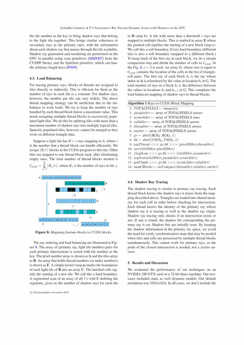
The ray ordering and load balancing are illustrated in Fig-ure 8. The array of (primary ray, light tile number) pairs foreach primary intersections is sorted with tile number as thekey. The pixel number array is shown asA and the tiles arrayas B. An array that holds thread numbers (or index numbers)is shown as F. A simple kernel (step a) marks the boundariesof each light tile of B into an array C. The hatched cells sig-nify the starting of a new tile. We call this a hard boundary.A segmented scan of an array of all 1’s with C defining thesegments, gives us the number of shadow rays for each tile
in D (step b). A tile with more than a threshold r rays aremapped to multiple blocks. This is marked in array E wherethe grained cell signifies the starting of a new block (step e).We call this a soft boundary. Every hard boundary (differenttile) is also a soft boundary (mapped to a different block.)To keep track of the first ray in each block, we do a streamcompaction step and shrink the number of cells to Ctotal . Inthe Fig. 8, r = 2 is used. An array G, whose size is equal toCtotal contains the location of the cells in the list of triangle-cell pairs. The first ray of each block bi is the ray whoseindex in A is referenced by the value in location bi in G. Thetotal number of rays in a block bi is the difference betweenthe values in locations bi and bi+1 in G. This completes theload-balanced mapping of shadow rays to thread blocks.
Algorithm 1 Rays to CUDA Block Mapping1: TOTALPIXELS← imagesize
2: pseudoArr← array of TOTALPIXELS zeroes3: scratchArr← array of TOTALPIXELS ones4: validArr← array of TOTALPIXELS zeroes5: threadArr← array of TOTALPIXELS zeroes6: outArr← array of TOTALPIXELS zeroes7: gr← dim3(BLKX ,BLKY ,1)8: bk← dim3(THDX ,THDY ,1)9: tagThread <<< gr,bk >>> (pixelIDArr, threadArr)
The shadow tracing is similar to primary ray tracing. Eachthread block knows the shadow rays it traces from the map-ping described above. Triangles are loaded into shared mem-ory for each cell in order before checking for intersection.Each thread knows the identity of the primary ray whoseshadow ray it is tracing as well as the shadow ray origin.Shadow ray tracing only checks if an intersection exists ornot. If one is found, the shadow bit corresponding the pri-mary ray is set. Shadow bits are initially reset. By keepingthe shadow information in the primary ray space, we avoidthe need for costly synchronization steps that may be neededwhen tiles and cells are processed by multiple thread blockssimultaneously. This cannot work for primary rays, as thepoint of the closest intersection is needed, not a yes/no an-swer.
5. Results and Discussion
We evaluated the performance of our techniques on anNVIDIA 280 GTX card on a 32-bit linux machine. Our test-cases included static as well dynamic models. Our defaultresolution was 1024x1024. In all cases, we don’t include the
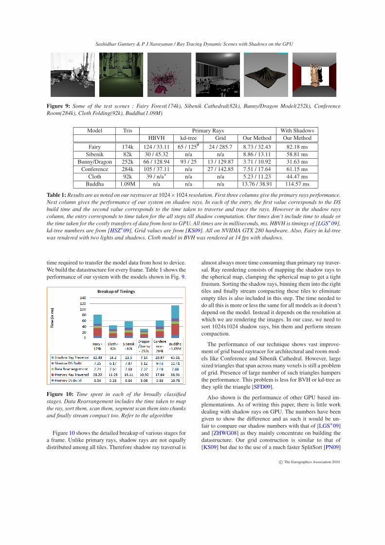
Table 1: Results are as noted on our raytracer at 1024×1024 resolution. First three columns give the primary rays performance.Next column gives the performance of our system on shadow rays. In each of the entry, the first value corresponds to the DS
build time and the second value corresponds to the time taken to traverse and trace the rays. However in the shadow rays
column, the entry corresponds to time taken for the all steps till shadow computation. Our times don’t include time to shade or
the time taken for the costly transfers of data from host to GPU. All times are in milliseconds, ms. HBVH is timings of [LGS∗09],
kd-tree numbers are from [HSZ∗09], Grid values are from [KS09]. All on NVIDIA GTX 280 hardware. Also, Fairy in kd-tree
was rendered with two lights and shadows. Cloth model in BVH was rendered at 14 fps with shadows.
time required to transfer the model data from host to device.We build the datastructure for every frame. Table 1 shows theperformance of our system with the models shown in Fig. 9.
Figure 10: Time spent in each of the broadly classified
stages. Data Rearrangement includes the time taken to map
the ray, sort them, scan them, segment scan them into chunks
and finally stream compact too. Refer to the algorithm
Figure 10 shows the detailed breakup of various stages fora frame. Unlike primary rays, shadow rays are not equallydistributed among all tiles. Therefore shadow ray traversal is
almost always more time consuming than primary ray traver-sal. Ray reordering consists of mapping the shadow rays tothe spherical map, clamping the spherical map to get a tightfrustum. Sorting the shadow rays, binning them into the righttiles and finally stream compacting these tiles to eliminateempty tiles is also included in this step. The time needed todo all this is more or less the same for all models as it doesn’tdepend on the model. Instead it depends on the resolution atwhich we are rendering the images. In our case, we need tosort 1024x1024 shadow rays, bin them and perform streamcompaction.
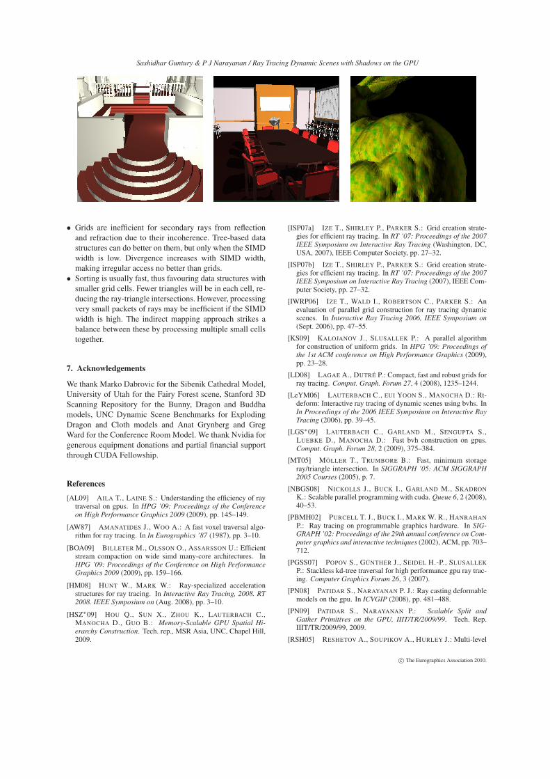
The performance of our technique shows vast improve-ment of grid based raytracer for architectural and roommod-els like Conference and Sibenik Cathedral. However, largesized triangles that span across many voxels is still a problemof grid. Presence of large number of such triangles hampersthe performance. This problem is less for BVH or kd-tree asthey split the triangle [SFD09].
Also shown is the performance of other GPU based im-plementations. As of writing this paper, there is little workdealing with shadow rays on GPU. The numbers have beengiven to show the difference and as such it would be un-fair to compare our shadow numbers with that of [LGS∗09]and [ZHWG08] as they mainly concentrate on building thedatastructure. Our grid construction is similar to that of[KS09] but due to the use of a much faster SplitSort [PN09]
Sashidhar Guntury & P J Narayanan / Ray Tracing Dynamic Scenes with Shadows on the GPU
routine, we build the grid very fast. We take advantage of thefact that the number of cells is less than 32 bits (in our caseit is 18) for splitting.
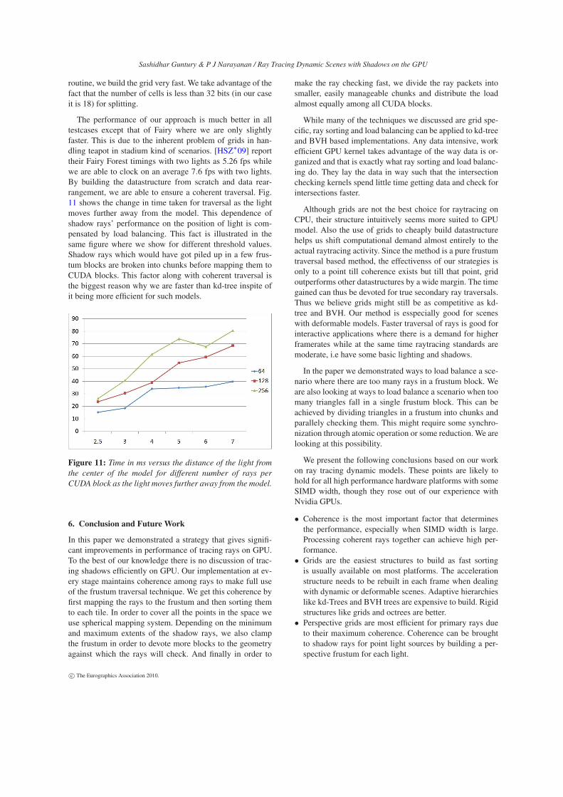
The performance of our approach is much better in alltestcases except that of Fairy where we are only slightlyfaster. This is due to the inherent problem of grids in han-dling teapot in stadium kind of scenarios. [HSZ∗09] reporttheir Fairy Forest timings with two lights as 5.26 fps whilewe are able to clock on an average 7.6 fps with two lights.By building the datastructure from scratch and data rear-rangement, we are able to ensure a coherent traversal. Fig.11 shows the change in time taken for traversal as the lightmoves further away from the model. This dependence ofshadow rays’ performance on the position of light is com-pensated by load balancing. This fact is illustrated in thesame figure where we show for different threshold values.Shadow rays which would have got piled up in a few frus-tum blocks are broken into chunks before mapping them toCUDA blocks. This factor along with coherent traversal isthe biggest reason why we are faster than kd-tree inspite ofit being more efficient for such models.
Figure 11: Time in ms versus the distance of the light from
the center of the model for different number of rays per
CUDA block as the light moves further away from the model.
6. Conclusion and Future Work
In this paper we demonstrated a strategy that gives signifi-cant improvements in performance of tracing rays on GPU.To the best of our knowledge there is no discussion of trac-ing shadows efficiently on GPU. Our implementation at ev-ery stage maintains coherence among rays to make full useof the frustum traversal technique. We get this coherence byfirst mapping the rays to the frustum and then sorting themto each tile. In order to cover all the points in the space weuse spherical mapping system. Depending on the minimumand maximum extents of the shadow rays, we also clampthe frustum in order to devote more blocks to the geometryagainst which the rays will check. And finally in order to
make the ray checking fast, we divide the ray packets intosmaller, easily manageable chunks and distribute the loadalmost equally among all CUDA blocks.
While many of the techniques we discussed are grid spe-cific, ray sorting and load balancing can be applied to kd-treeand BVH based implementations. Any data intensive, workefficient GPU kernel takes advantage of the way data is or-ganized and that is exactly what ray sorting and load balanc-ing do. They lay the data in way such that the intersectionchecking kernels spend little time getting data and check forintersections faster.
Although grids are not the best choice for raytracing onCPU, their structure intuitively seems more suited to GPUmodel. Also the use of grids to cheaply build datastructurehelps us shift computational demand almost entirely to theactual raytracing activity. Since the method is a pure frustumtraversal based method, the effectivenss of our strategies isonly to a point till coherence exists but till that point, gridoutperforms other datastructures by a wide margin. The timegained can thus be devoted for true secondary ray traversals.Thus we believe grids might still be as competitive as kd-tree and BVH. Our method is esspecially good for sceneswith deformable models. Faster traversal of rays is good forinteractive applications where there is a demand for higherframerates while at the same time raytracing standards aremoderate, i.e have some basic lighting and shadows.
In the paper we demonstrated ways to load balance a sce-nario where there are too many rays in a frustum block. Weare also looking at ways to load balance a scenario when toomany triangles fall in a single frustum block. This can beachieved by dividing triangles in a frustum into chunks andparallely checking them. This might require some synchro-nization through atomic operation or some reduction. We arelooking at this possibility.
We present the following conclusions based on our workon ray tracing dynamic models. These points are likely tohold for all high performance hardware platforms with someSIMD width, though they rose out of our experience withNvidia GPUs.
• Coherence is the most important factor that determinesthe performance, especially when SIMD width is large.Processing coherent rays together can achieve high per-formance.
• Grids are the easiest structures to build as fast sortingis usually available on most platforms. The accelerationstructure needs to be rebuilt in each frame when dealingwith dynamic or deformable scenes. Adaptive hierarchieslike kd-Trees and BVH trees are expensive to build. Rigidstructures like grids and octrees are better.
• Perspective grids are most efficient for primary rays dueto their maximum coherence. Coherence can be broughtto shadow rays for point light sources by building a per-spective frustum for each light.
Sashidhar Guntury & P J Narayanan / Ray Tracing Dynamic Scenes with Shadows on the GPU
• Grids are inefficient for secondary rays from reflectionand refraction due to their incoherence. Tree-based datastructures can do better on them, but only when the SIMDwidth is low. Divergence increases with SIMD width,making irregular access no better than grids.
• Sorting is usually fast, thus favouring data structures withsmaller grid cells. Fewer triangles will be in each cell, re-ducing the ray-triangle intersections. However, processingvery small packets of rays may be inefficient if the SIMDwidth is high. The indirect mapping approach strikes abalance between these by processing multiple small cellstogether.
7. Acknowledgements
We thank Marko Dabrovic for the Sibenik Cathedral Model,University of Utah for the Fairy Forest scene, Stanford 3DScanning Repository for the Bunny, Dragon and Buddhamodels, UNC Dynamic Scene Benchmarks for ExplodingDragon and Cloth models and Anat Grynberg and GregWard for the Conference Room Model. We thank Nvidia forgenerous equipment donations and partial financial supportthrough CUDA Fellowship.
References
[AL09] AILA T., LAINE S.: Understanding the efficiency of raytraversal on gpus. In HPG ’09: Proceedings of the Conference
on High Performance Graphics 2009 (2009), pp. 145–149.
[AW87] AMANATIDES J., WOO A.: A fast voxel traversal algo-rithm for ray tracing. In In Eurographics ’87 (1987), pp. 3–10.
[BOA09] BILLETER M., OLSSON O., ASSARSSON U.: Efficientstream compaction on wide simd many-core architectures. InHPG ’09: Proceedings of the Conference on High Performance
Graphics 2009 (2009), pp. 159–166.
[HM08] HUNT W., MARK W.: Ray-specialized accelerationstructures for ray tracing. In Interactive Ray Tracing, 2008. RT
2008. IEEE Symposium on (Aug. 2008), pp. 3–10.
[HSZ∗09] HOU Q., SUN X., ZHOU K., LAUTERBACH C.,MANOCHA D., GUO B.: Memory-Scalable GPU Spatial Hi-
[ISP07a] IZE T., SHIRLEY P., PARKER S.: Grid creation strate-gies for efficient ray tracing. In RT ’07: Proceedings of the 2007
IEEE Symposium on Interactive Ray Tracing (Washington, DC,USA, 2007), IEEE Computer Society, pp. 27–32.
[ISP07b] IZE T., SHIRLEY P., PARKER S.: Grid creation strate-gies for efficient ray tracing. In RT ’07: Proceedings of the 2007
IEEE Symposium on Interactive Ray Tracing (2007), IEEE Com-puter Society, pp. 27–32.
[IWRP06] IZE T., WALD I., ROBERTSON C., PARKER S.: Anevaluation of parallel grid construction for ray tracing dynamicscenes. In Interactive Ray Tracing 2006, IEEE Symposium on
(Sept. 2006), pp. 47–55.
[KS09] KALOJANOV J., SLUSALLEK P.: A parallel algorithmfor construction of uniform grids. In HPG ’09: Proceedings of
the 1st ACM conference on High Performance Graphics (2009),pp. 23–28.
[LD08] LAGAE A., DUTRÉ P.: Compact, fast and robust grids forray tracing. Comput. Graph. Forum 27, 4 (2008), 1235–1244.
[LeYM06] LAUTERBACH C., EUI YOON S., MANOCHA D.: Rt-deform: Interactive ray tracing of dynamic scenes using bvhs. InIn Proceedings of the 2006 IEEE Symposium on Interactive Ray
Tracing (2006), pp. 39–45.
[LGS∗09] LAUTERBACH C., GARLAND M., SENGUPTA S.,LUEBKE D., MANOCHA D.: Fast bvh construction on gpus.Comput. Graph. Forum 28, 2 (2009), 375–384.
Sashidhar Guntury & P J Narayanan / Ray Tracing Dynamic Scenes with Shadows on the GPU
ray tracing algorithm. ACM Trans. Graph. 24, 3 (2005), 1176–1185.
[SFD09] STICH M., FRIEDRICH H., DIETRICH A.: Spatial splitsin bounding volume hierarchies. In HPG ’09: Proceedings of the
Conference on High Performance Graphics 2009 (2009), pp. 7–13.
[SHG09] SATISH N., HARRIS M., GARLAND M.: Designingefficient sorting algorithms for manycore gpus. In IPDPS (2009),pp. 1–10.
[SHZO07] SENGUPTA S., HARRIS M., ZHANG Y., OWENS
J. D.: Scan primitives for gpu computing. In Graphics Hard-
ware (2007), pp. 97–106.
[SSK07] SHEVTSOV M., SOUPIKOV A., KAPUSTIN E.: Highlyparallel fast kd-tree construction for interactive ray tracing of dy-namic scenes. Computer Graphics Forum 26, 3 (2007).
[WBS07] WALD I., BOULOS S., SHIRLEY P.: Ray tracing de-formable scenes using dynamic bounding volume hierarchies.ACM Trans. Graph. 26, 1 (2007).
[WGBK07] WALD I., GRIBBLE P. C., BOULOS S., KENSLER
A.: SIMD Ray Stream Tracing - SIMD Ray Traversal with Gen-
eralized Ray Packets and On-the-fly Re-Ordering. Tech. Rep.UUSCI-2007-012, 2007.
[WIK∗06] WALD I., IZE T., KENSLER A., KNOLL A., PARKER
S. G.: Ray tracing animated scenes using coherent grid traversal.ACM Trans. Graph. 25, 3 (2006), 485–493.
[WMG∗07] WALD I., MARK W. R., GÃIJNTHER J., BOULOS
S., IZE T., HUNT W., PARKER S. G., SHIRLEY P.: State of theArt in Ray Tracing Animated Scenes . pp. 89–116.
[ZHWG08] ZHOU K., HOU Q., WANG R., GUO B.: Real-timekd-tree construction on graphics hardware. ACM Trans. Graph.