Available online at www.scholarsresearchlibrary.com Scholars Research Library European Journal of Applied Engineering and Scientific Research, 2013, 2 (2):8-22 (http://scholarsresearchlibrary.com/archive.html) ISSN: 2278 – 0041 8 Scholars Research Library Layered Elastic Analysis and Design Tool for Predicting Fatigue and Rutting Strains in Low Volume Asphalt Pavement in Nigeria. 1 E. O. Ekwulo, 2 J. C. Agunwamba 1 Department of Civil Engineering, Rivers State University of Science and Technology, Nkpolu Oroworukwo, Port Harcourt Nigeria 2 Department of Civil Engineering, University of Nigeria, Nssuka, Nigeria _____________________________________________________________________________________ ABSTRACT Failure of asphalt pavements is generally attributed to fatigue cracking and rutting deformation, caused by excessive horizontal tensile strain at the bottom of the asphalt layer due to repeated traffic loading and excessive vertical compressive strain on top of the subgrade due to densification and shear deformation of subgrade. In the design of asphalt pavement, it is necessary to investigate these critical strains and design against them. This study was conducted to develop a simplified layered elastic analysis and design procedure to predict fatigue and rutting strain in cement-stabilized lateritic base, low-volume asphalt pavement. The major focus of the study was to develop a design procedure which involves selection of pavement material properties and thickness such that fatigue and rutting strains developed due to traffic loading are within the allowable limit to prevent fatigue cracking and rutting deformation. Analysis was performed for hypothetical asphalt pavement sections subjected to traffic load using the layered elastic analysis program EVERSTRESS. Predictive regression equations were developed for the prediction of pavement thickness, fatigue (tensile) strain below asphalt layer and rutting (compressive) strain on top the subgrade. The regression equations were used to develop a layered elastic analysis and design tool (program) LEADFlex. The average ratio of the LEADflex-calculated and measured tensile strains were found to be 1.04 and 1.02 respectively. The procedure was validated by comparing predicted (calculated) fatigue and rutting strains with measured field data using linear regression analysis. The coefficients of determination (R 2 ) were found to be very good with R 2 of 0.999 and 0.994 for fatigue and rutting strains respectively indicating that LEADFlex is a good predictor of fatigue and rutting strain in cement-stabilized lateritic base, low-volume asphalt pavement. Keywords: Layered Elastic Analysis, Design Tool, Fatigue and Rutting Strain, Asphalt Pavement _____________________________________________________________________________________________ INTRODUCTION Since the early 1800’s when the first paved highways were built, construction of roads has been on the increase as well as improved method of construction. The need for stronger, long-lasting and all-weather pavements has become a priority as result of rapid growth in the automobile traffic and the development of modern civilization. Since the beginning of road building, modelling of highway and airport pavements have been a difficult task. These difficulties are due to the complexity of the pavement system with many variables such as thickness, type of material, environment and traffic. Road failures in most developing tropical countries like Nigeria have been traced to common causes which can broadly be attributed to any or combination of geological, geotechnical, design, construction, and maintenance problems (Ajayi, 1987). Several studies have been carried out to trace the cause of early road failures, studies were carried out by researchers on the geological (Ajayi, 1987), geotechnical, (Oyediran, 2001), Construction (Eze- Uzomaka, 1981) and maintenance (Busari, 1990) factors. However, the design factor has not been given adequate
Transcript
Available online at www.scholarsresearchlibrary.com
Scholars Research Library
European Journal of Applied Engineering and Scientific Research, 2013, 2 (2):8-22
(http://scholarsresearchlibrary.com/archive.html)
ISSN: 2278 – 0041
8
Scholars Research Library
Layered Elastic Analysis and Design Tool for Predicting Fatigue and Rutting Strains in Low Volume Asphalt Pavement in Nigeria.
1E. O. Ekwulo, 2J. C. Agunwamba
1Department of Civil Engineering, Rivers State University of Science and Technology, Nkpolu
Oroworukwo, Port Harcourt Nigeria 2Department of Civil Engineering, University of Nigeria, Nssuka, Nigeria
ABSTRACT Failure of asphalt pavements is generally attributed to fatigue cracking and rutting deformation, caused by excessive horizontal tensile strain at the bottom of the asphalt layer due to repeated traffic loading and excessive vertical compressive strain on top of the subgrade due to densification and shear deformation of subgrade. In the design of asphalt pavement, it is necessary to investigate these critical strains and design against them. This study was conducted to develop a simplified layered elastic analysis and design procedure to predict fatigue and rutting strain in cement-stabilized lateritic base, low-volume asphalt pavement. The major focus of the study was to develop a design procedure which involves selection of pavement material properties and thickness such that fatigue and rutting strains developed due to traffic loading are within the allowable limit to prevent fatigue cracking and rutting deformation. Analysis was performed for hypothetical asphalt pavement sections subjected to traffic load using the layered elastic analysis program EVERSTRESS. Predictive regression equations were developed for the prediction of pavement thickness, fatigue (tensile) strain below asphalt layer and rutting (compressive) strain on top the subgrade. The regression equations were used to develop a layered elastic analysis and design tool (program) LEADFlex. The average ratio of the LEADflex-calculated and measured tensile strains were found to be 1.04 and 1.02 respectively. The procedure was validated by comparing predicted (calculated) fatigue and rutting strains with measured field data using linear regression analysis. The coefficients of determination (R2) were found to be very good with R2 of 0.999 and 0.994 for fatigue and rutting strains respectively indicating that LEADFlex is a good predictor of fatigue and rutting strain in cement-stabilized lateritic base, low-volume asphalt pavement. Keywords: Layered Elastic Analysis, Design Tool, Fatigue and Rutting Strain, Asphalt Pavement _____________________________________________________________________________________________
INTRODUCTION
Since the early 1800’s when the first paved highways were built, construction of roads has been on the increase as well as improved method of construction. The need for stronger, long-lasting and all-weather pavements has become a priority as result of rapid growth in the automobile traffic and the development of modern civilization. Since the beginning of road building, modelling of highway and airport pavements have been a difficult task. These difficulties are due to the complexity of the pavement system with many variables such as thickness, type of material, environment and traffic. Road failures in most developing tropical countries like Nigeria have been traced to common causes which can broadly be attributed to any or combination of geological, geotechnical, design, construction, and maintenance problems (Ajayi, 1987). Several studies have been carried out to trace the cause of early road failures, studies were carried out by researchers on the geological (Ajayi, 1987), geotechnical, (Oyediran, 2001), Construction (Eze-Uzomaka, 1981) and maintenance (Busari, 1990) factors. However, the design factor has not been given adequate
E. O. Ekwulo et al Euro. J. Appl. Eng. Sci. Res., 2013, 2 (2):8-22 ______________________________________________________________________________
9
Scholars Research Library
attention. In Nigeria, the only developed design method for asphalt pavement is the California Bearing Ratio (CBR) method. This method uses the California Bearing Ratio and traffic volume as the sole design inputs. The method was originally developed by the U.S Corps of Engineers and modified by the British Transportation Research Laboratory (TRL, 1970), it was adopted by Nigeria as contained in the Federal Highway Manual (Highway Manual-Part 1, 1973). Most of the roads designed using the CBR method failed soon after construction by either fatigue cracking or rutting deformation or both. In their researches (Emesiobi, 2004, Ekwulo et al , 2009), a comparative analysis of flexible pavements designed using three different CBR procedures were carried out, result indicated that the pavements designed by the CBR-based methods are prone to both fatigue cracking and rutting deformation. The CBR method was abandoned in California over 50 years ago (Brown, 1997) for the more reliable mechanistic-empirical methods (Layered Elastic Analysis or Finite Element Methods). It is regrettable that this old method is still being used by most designers in Nigeria and has resulted in unsatisfactory designs, leading to frequent early pavement failures. In Pavement Engineering, it is generally known that the major causes of failure of asphalt pavement is fatigue cracking and rutting deformation, caused by excessive horizontal tensile strain at the bottom of the asphalt layer and vertical compressive strain on top of the subgrade due to repeated traffic loading (Yang, 1973; Saal and Pell, 1960; Dormon and Metcaff, 1965; NCHRP, 2007)). In the design of asphalt pavement, it is necessary to investigate these critical strains and design against them. There is currently no pavement design method in Nigeria that is based on analytical approach in which properties and thickness of the pavement layers are selected such that strains developed due to traffic loading do not exceed the capability of any of the materials in the pavement in order to withstand the expected traffic. Pavement structural design for low volume roads considers two types of pavements; asphalt pavement with asphalt concrete surface and base course, and jointed plain concrete pavements (NCHRP, 2004). The National Cooperative Highway Research Program (NCHRP, 2004) defines low volume roads as roads that can withstand up to 750,000 Equivalent Single Axle Loads (ESAL) as practical maximum within a design period of 20 years. As a result of the high abundance of laterite in Nigeria and most developing countries in Africa, it is widely used as base material for construction of cost effective low-volume asphalt roads. However, due to lack of proper consideration for the qualities and properties of laterite used as road base material, the roads fail soon after construction. It is therefore necessary to adequately characterize such materials and improve their quality where necessary. The purpose of this study therefore is to develop a layered elastic design procedure to predict critical horizontal tensile strain at the bottom of the asphalt bound layer and vertical compressive strain on top of the subgrade in cement-stabilized low volume asphalt Pavement.
MATERIALS AND METHODS
The method adopted in this study is to use the layered elastic analysis and design approach to develop a procedure that will predict fatigue and rutting strains in cement-stabilized lateritic base, low volume asphalt pavement. To achieve this, the study was carried out in the following order:
1. Characterize pavement materials in terms of elastic modulus, CBR, resilient modulus and poison’s ratio. 2. Obtain traffic data needed for the entire design period. 3. Compute fatigue and rutting strains using layered elastic analysis based the Asphalt Institute response
models. 4. Evaluate and predict pavement responses (tensile strain, compressive strain and allowable repetitions to
failure). 5. Develop simple regression design equations to predict pavement thickness, maximum fatigue and rutting
strains such that the strains are within allowable limits. The procedure was implemented in software (LEADFlex) in which all the above steps are performed automatically, except the material selection. Traffic estimation was in the form of Equivalent Single Axle Load (ESAL). The elastic properties (resilient modulus for subgrade, elastic modulus for base and subbase, and Poisson’s ratio) of the pavement material are used as inputs for design and analysis. The resilient modulus is obtained through correlation with CBR. The layered elastic analysis software EVERSRESS (Sivaneswaran et al, 2001) was employed in the analysis.
E. O. Ekwulo et al Euro. J. Appl. Eng. Sci. Res., 2013, 2 (2):8-22 ______________________________________________________________________________
10
Scholars Research Library
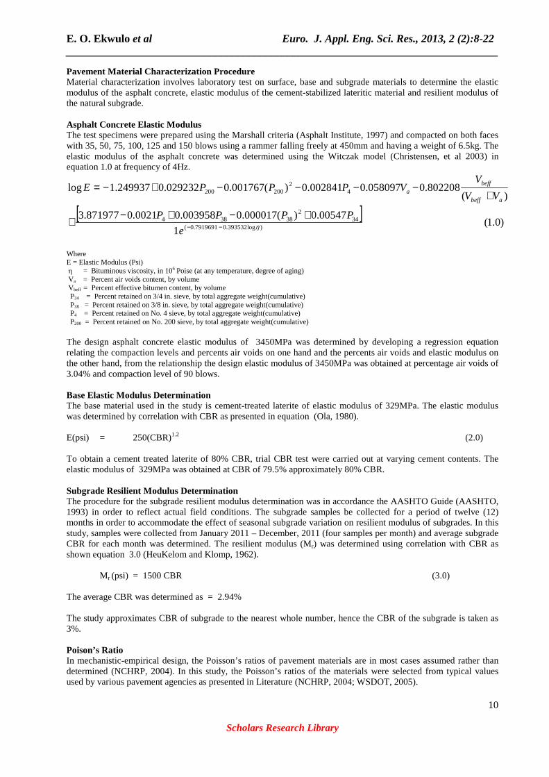
Pavement Material Characterization Procedure Material characterization involves laboratory test on surface, base and subgrade materials to determine the elastic modulus of the asphalt concrete, elastic modulus of the cement-stabilized lateritic material and resilient modulus of the natural subgrade. Asphalt Concrete Elastic Modulus The test specimens were prepared using the Marshall criteria (Asphalt Institute, 1997) and compacted on both faces with 35, 50, 75, 100, 125 and 150 blows using a rammer falling freely at 450mm and having a weight of 6.5kg. The elastic modulus of the asphalt concrete was determined using the Witczak model (Christensen, et al 2003) in equation 1.0 at frequency of 4Hz.
Where E = Elastic Modulus (Psi) η = Bituminous viscosity, in 106 Poise (at any temperature, degree of aging) Va = Percent air voids content, by volume Vbeff = Percent effective bitumen content, by volume P34 = Percent retained on 3/4 in. sieve, by total aggregate weight(cumulative) P38 = Percent retained on 3/8 in. sieve, by total aggregate weight(cumulative) P4 = Percent retained on No. 4 sieve, by total aggregate weight(cumulative) P200 = Percent retained on No. 200 sieve, by total aggregate weight(cumulative) The design asphalt concrete elastic modulus of 3450MPa was determined by developing a regression equation relating the compaction levels and percents air voids on one hand and the percents air voids and elastic modulus on the other hand, from the relationship the design elastic modulus of 3450MPa was obtained at percentage air voids of 3.04% and compaction level of 90 blows. Base Elastic Modulus Determination The base material used in the study is cement-treated laterite of elastic modulus of 329MPa. The elastic modulus was determined by correlation with CBR as presented in equation (Ola, 1980). E(psi) = 250(CBR)1.2 (2.0) To obtain a cement treated laterite of 80% CBR, trial CBR test were carried out at varying cement contents. The elastic modulus of 329MPa was obtained at CBR of 79.5% approximately 80% CBR. Subgrade Resilient Modulus Determination The procedure for the subgrade resilient modulus determination was in accordance the AASHTO Guide (AASHTO, 1993) in order to reflect actual field conditions. The subgrade samples be collected for a period of twelve (12) months in order to accommodate the effect of seasonal subgrade variation on resilient modulus of subgrades. In this study, samples were collected from January 2011 – December, 2011 (four samples per month) and average subgrade CBR for each month was determined. The resilient modulus (Mr) was determined using correlation with CBR as shown equation 3.0 (HeuKelom and Klomp, 1962).
Mr (psi) = 1500 CBR (3.0) The average CBR was determined as = 2.94% The study approximates CBR of subgrade to the nearest whole number, hence the CBR of the subgrade is taken as 3%. Poison’s Ratio In mechanistic-empirical design, the Poisson’s ratios of pavement materials are in most cases assumed rather than determined (NCHRP, 2004). In this study, the Poisson’s ratios of the materials were selected from typical values used by various pavement agencies as presented in Literature (NCHRP, 2004; WSDOT, 2005).
E. O. Ekwulo et al Euro. J. Appl. Eng. Sci. Res., 2013, 2 (2):8-22 ______________________________________________________________________________
11
Scholars Research Library
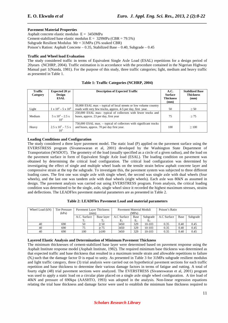
Pavement Material Properties Asphalt concrete elastic modulus E = 3450MPa Cement-stabilized base elastic modulus E = 329MPa (CBR = 79.5%) Subgrade Resilient Modulus Mr = 31MPa (3% soaked CBR) Poison’s Ration: Asphalt Concrete – 0.35, Stabilized Base – 0.40, Subgrade – 0.45 Traffic and Wheel load Evaluation The study considered traffic in terms of Equivalent Single Axle Load (ESAL) repetitions for a design period of 20years (NCHRP, 2004). Traffic estimation is in accordance with the procedure contained in the Nigerian Highway Manual part 1(Nanda, 1981). For the purpose of this study, three traffic categories; light, medium and heavy traffic as presented in Table 1.
Table 1: Traffic Categories (NCHRP, 2004)
Traffic Category
Expected 20 yr Design ESAL
Description of Expected Traffic A.C. Surface
Thickness (mm)
Stabilized Base Thickness
(mm)
Light
1 x 10⁴ – 5 x 10⁴
50,000 ESAL max – typical of local streets or low volume country roads with very few trucks, approx. 4-5 per day, first year.
50
≥ 50
Medium
5 x 10⁴ – 2.5 x
105
250,000 ESAL max– typical of collectors with fewer trucks and buses, approx. 23 per day, first year
75
≥ 75
Heavy
2.5 x 10⁵ – 7.5 x
105
750,000 ESAL max. – typical of collectors with significant trucks and buses, approx. 70 per day first year.
100
≥ 100
Loading Conditions and Configuration The study considered a three layer pavement model. The static load (P) applied on the pavement surface using the EVERSTRESS program (Sivaneswaran et al, 2001) developed by the Washington State Department of Transportation (WSDOT). The geometry of the load (usually specified as a circle of a given radius), and the load on the pavement surface in form of Equivalent Single Axle load (ESAL). The loading condition on pavement was obtained by determining the critical load configuration. The critical load configuration was determined by investigating the effect of single and multiple wheel loads on the tensile strain below asphalt concrete layer and compressive strain at the top the subgrade. To investigate this, the pavement system was subjected to three different loading cases. The first one was single axle with single wheel, the second was single axle with dual wheels (four wheels), and the last one was tandem axle with dual wheels (eight wheels). Each axle was 80kN as assumed in design. The pavement analysis was carried out using EVERSTRESS program. From analysis, the critical loading condition was determined to be the single, axle, single wheel since it recorded the highest maximum stresses, strains and deflections. The LEADFlex pavement material parameters are as presented in Table 2.
Table 2: LEADFlex Pavement Load and material parameters
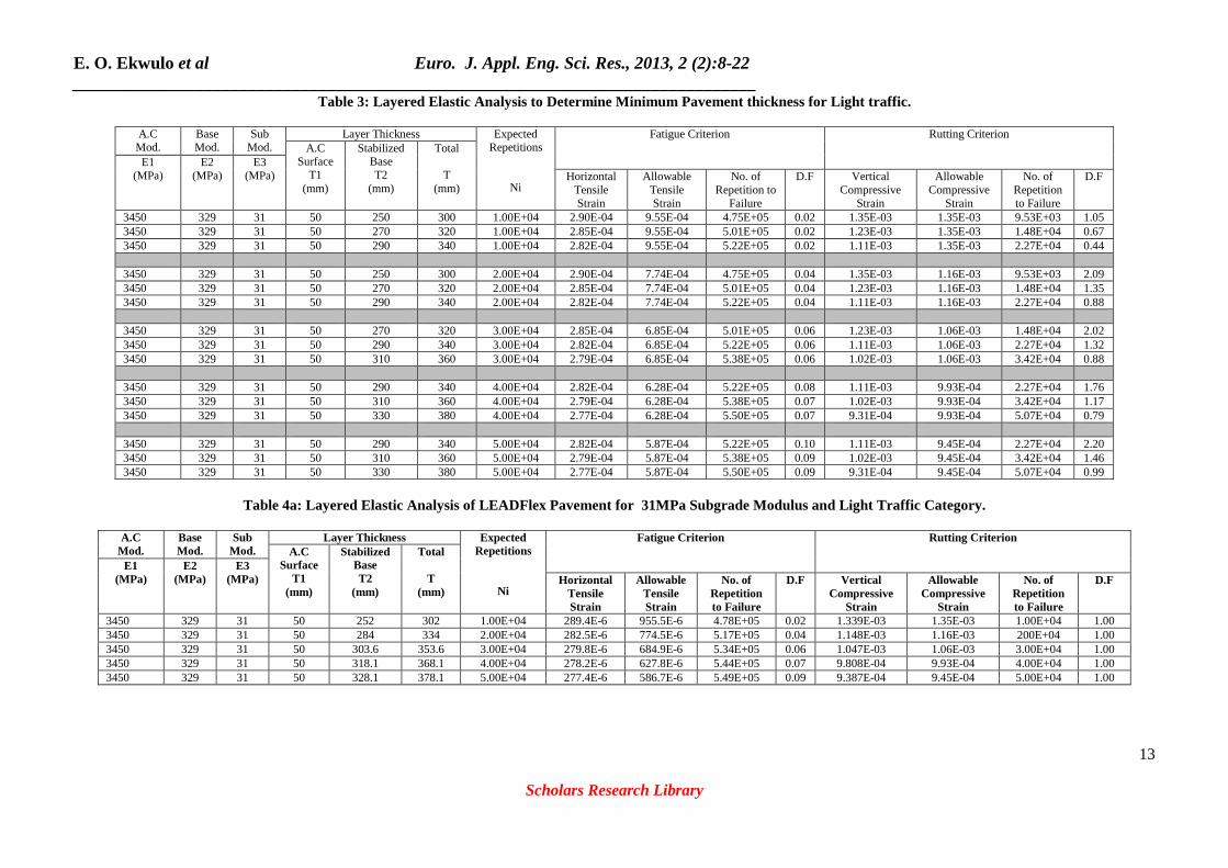
Layered Elastic Analysis and Determination of Minimum Pavement Thickness The minimum thicknesses of cement-stabilized base layer were determined based on pavement response using the Asphalt Institute response model (Asphalt Institute, 1982). The required minimum base thickness was determined as that expected traffic and base thickness that resulted in a maximum tensile strain and allowable repetitions to failure (Nr) such that the damage factor D is equal to unity. As presented in Table 3 for 31MPa subgrade resilient modulus and light traffic category, three (3) trial analysis were carried out on hypothetical pavement sections for each traffic repetition and base thickness to determine their various damage factors in terms of fatigue and rutting. A total of fourty eight (48) trial pavement sections were analyzed. The EVERSTRESS (Sivaneswaran et al, 2001) program was used to apply a static load on a circular plate placed on a single axle single wheel configuration. A tire load of 40kN and pressure of 690kpa (AASHTO, 1993) was adopted in the analysis. Non-linear regression equations relating the trial base thickness and damage factor were used to establish the minimum base thickness required to
E. O. Ekwulo et al Euro. J. Appl. Eng. Sci. Res., 2013, 2 (2):8-22 ______________________________________________________________________________
12
Scholars Research Library
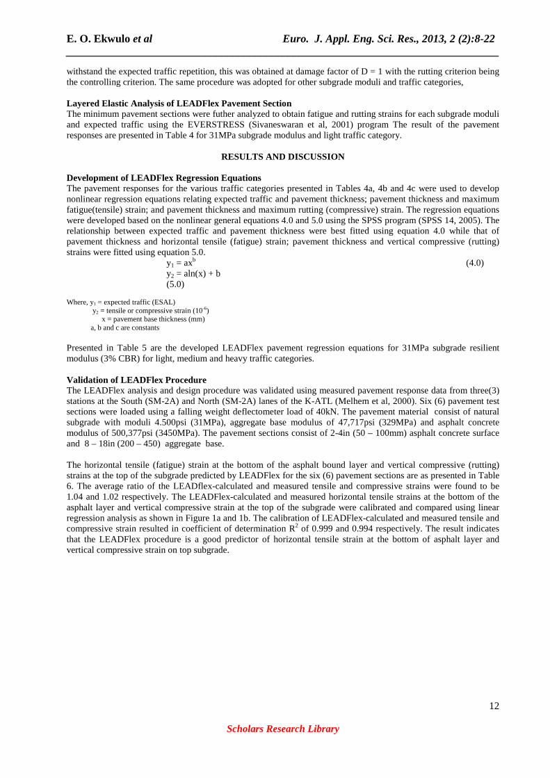
withstand the expected traffic repetition, this was obtained at damage factor of D = 1 with the rutting criterion being the controlling criterion. The same procedure was adopted for other subgrade moduli and traffic categories, Layered Elastic Analysis of LEADFlex Pavement Section The minimum pavement sections were futher analyzed to obtain fatigue and rutting strains for each subgrade moduli and expected traffic using the EVERSTRESS (Sivaneswaran et al, 2001) program The result of the pavement responses are presented in Table 4 for 31MPa subgrade modulus and light traffic category.
RESULTS AND DISCUSSION
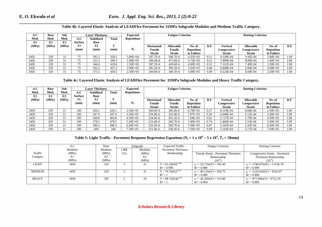
Development of LEADFlex Regression Equations The pavement responses for the various traffic categories presented in Tables 4a, 4b and 4c were used to develop nonlinear regression equations relating expected traffic and pavement thickness; pavement thickness and maximum fatigue(tensile) strain; and pavement thickness and maximum rutting (compressive) strain. The regression equations were developed based on the nonlinear general equations 4.0 and 5.0 using the SPSS program (SPSS 14, 2005). The relationship between expected traffic and pavement thickness were best fitted using equation 4.0 while that of pavement thickness and horizontal tensile (fatigue) strain; pavement thickness and vertical compressive (rutting) strains were fitted using equation 5.0.
y1 = axb (4.0) y2 = aln(x) + b
(5.0)
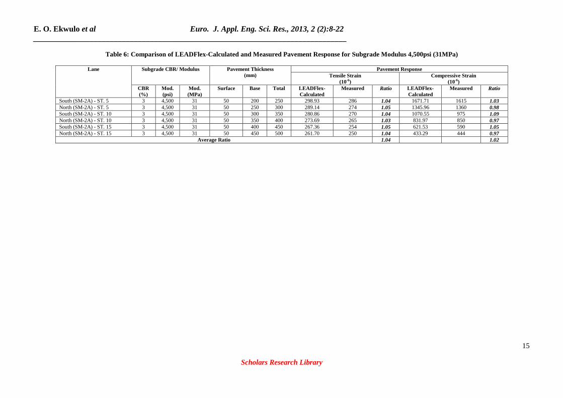
Where, y1 = expected traffic (ESAL) y2 = tensile or compressive strain (10-6) x = pavement base thickness (mm) a, b and c are constants Presented in Table 5 are the developed LEADFlex pavement regression equations for 31MPa subgrade resilient modulus (3% CBR) for light, medium and heavy traffic categories. Validation of LEADFlex Procedure The LEADFlex analysis and design procedure was validated using measured pavement response data from three(3) stations at the South (SM-2A) and North (SM-2A) lanes of the K-ATL (Melhem et al, 2000). Six (6) pavement test sections were loaded using a falling weight deflectometer load of 40kN. The pavement material consist of natural subgrade with moduli 4.500psi (31MPa), aggregate base modulus of 47,717psi (329MPa) and asphalt concrete modulus of 500,377psi (3450MPa). The pavement sections consist of 2-4in (50 – 100mm) asphalt concrete surface and 8 – 18in (200 – 450) aggregate base. The horizontal tensile (fatigue) strain at the bottom of the asphalt bound layer and vertical compressive (rutting) strains at the top of the subgrade predicted by LEADFlex for the six (6) pavement sections are as presented in Table 6. The average ratio of the LEADflex-calculated and measured tensile and compressive strains were found to be 1.04 and 1.02 respectively. The LEADFlex-calculated and measured horizontal tensile strains at the bottom of the asphalt layer and vertical compressive strain at the top of the subgrade were calibrated and compared using linear regression analysis as shown in Figure 1a and 1b. The calibration of LEADFlex-calculated and measured tensile and compressive strain resulted in coefficient of determination R2 of 0.999 and 0.994 respectively. The result indicates that the LEADFlex procedure is a good predictor of horizontal tensile strain at the bottom of asphalt layer and vertical compressive strain on top subgrade.
E. O. Ekwulo et al Euro. J. Appl. Eng. Sci. Res., 2013, 2 (2):8-22 ______________________________________________________________________________
13
Scholars Research Library
Table 3: Layered Elastic Analysis to Determine Minimum Pavement thickness for Light traffic.
E. O. Ekwulo et al Euro. J. Appl. Eng. Sci. Res., 2013, 2 (2):8-22 ______________________________________________________________________________
15
Scholars Research Library
Table 6: Comparison of LEADFlex-Calculated and Measured Pavement Response for Subgrade Modulus 4,500psi (31MPa)
Lane
Subgrade CBR/ Modulus
Pavement Thickness
(mm)
Pavement Response Tensile Strain
(10-6) Compressive Strain
(10-6) CBR (%)
Mod. (psi)
Mod. (MPa)
Surface Base Total LEADFlex- Calculated
Measured Ratio LEADFlex- Calculated
Measured
Ratio
South (SM-2A) - ST. 5 3 4,500 31 50 200 250 298.93 286 1.04 1671.71 1615 1.03 North (SM-2A) - ST. 5 3 4,500 31 50 250 300 289.14 274 1.05 1345.96 1360 0.98 South (SM-2A) - ST. 10 3 4,500 31 50 300 350 280.86 270 1.04 1070.55 975 1.09 North (SM-2A) - ST. 10 3 4,500 31 50 350 400 273.69 265 1.03 831.97 850 0.97 South (SM-2A) - ST. 15 3 4,500 31 50 400 450 267.36 254 1.05 621.53 590 1.05 North (SM-2A) - ST. 15 3 4,500 31 50 450 500 261.70 250 1.04 433.29 444 0.97
Average Ratio 1.04 1.02
E. O. Ekwulo et al Euro. J. Appl. Eng. Sci. Res., 2013, 2 (2):8-22 ______________________________________________________________________________
16
Scholars Research Library
Figure 1a: Calibration of Calculated and Measured Tensile Strain for 31MPa Subgrade Modulus
Figure 1b: Calibration of Calculated and Measured Compressive Strain for 31MPa Subgrade Modulus CBR
E. O. Ekwulo et al Euro. J. Appl. Eng. Sci. Res., 2013, 2 (2):8-22 ______________________________________________________________________________
17
Scholars Research Library
Developlemt of LEADFlex Program The LEADFlex programme was developed using algorithm and Visual Basis Codes. The program algorithm is as presented below; Program Algorithm
1. Enter the traffic data, material and pavement layer thickness 2. Compute the Expected Traffic – Ni (ESAL) 3. Check if the Traffic Category is Light, Medium or Heavy Traffic 4. Compute the minimum pavement thickness 5. Compute the Maximum tensile and compressive Strain and
5.1 Check if maximum tensile strain is less that allowable 5.2 Check if maximum compressive strain is less than available
6. Compute number of traffic repetitions to failure for fatigue and rutting 7. Compute Damage Factor for fatigue and rutting
7.1.1 Check if the Damage Factor for fatigue Df is less than 1. If Df is less than 1 go to 8 otherwise go to 4 and increase pavement thickness.
7.1.2 Check if the Damage Factor for rutting Dr is less than 1. If Dr is less than 1 go to 8 otherwise go to 4 and increase pavement thickness.
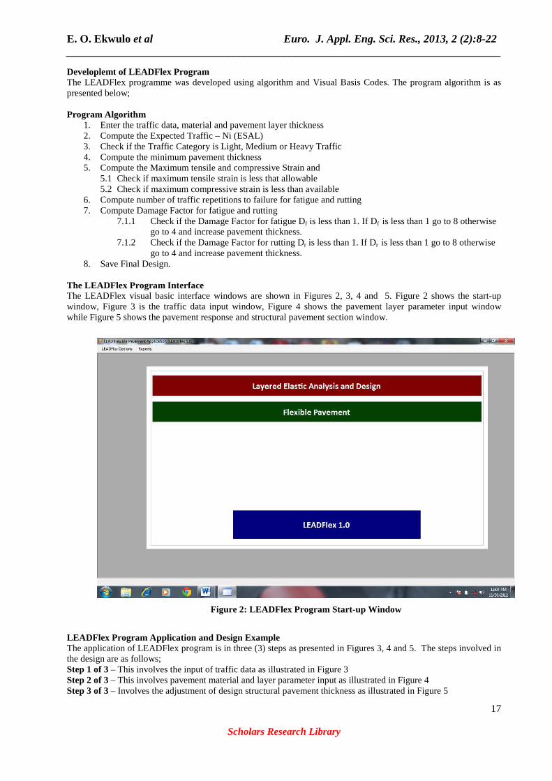
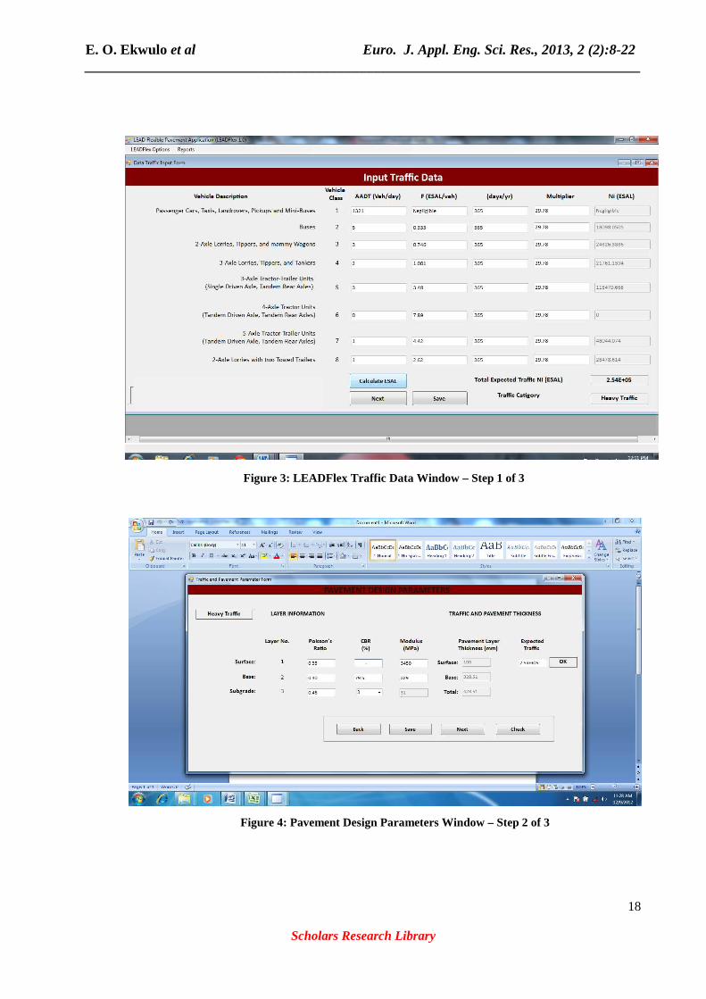
8. Save Final Design. The LEADFlex Program Interface The LEADFlex visual basic interface windows are shown in Figures 2, 3, 4 and 5. Figure 2 shows the start-up window, Figure 3 is the traffic data input window, Figure 4 shows the pavement layer parameter input window while Figure 5 shows the pavement response and structural pavement section window. LEADFlex Program Application and Design Example The application of LEADFlex program is in three (3) steps as presented in Figures 3, 4 and 5. The steps involved in the design are as follows; Step 1 of 3 – This involves the input of traffic data as illustrated in Figure 3 Step 2 of 3 – This involves pavement material and layer parameter input as illustrated in Figure 4 Step 3 of 3 – Involves the adjustment of design structural pavement thickness as illustrated in Figure 5
Figure 2: LEADFlex Program Start-up Window
E. O. Ekwulo et al Euro. J. Appl. Eng. Sci. Res., 2013, 2 (2):8-22 ______________________________________________________________________________
18
Scholars Research Library
Figure 3: LEADFlex Traffic Data Window – Step 1 of 3
E. O. Ekwulo et al Euro. J. Appl. Eng. Sci. Res., 2013, 2 (2):8-22 ______________________________________________________________________________
19
Scholars Research Library
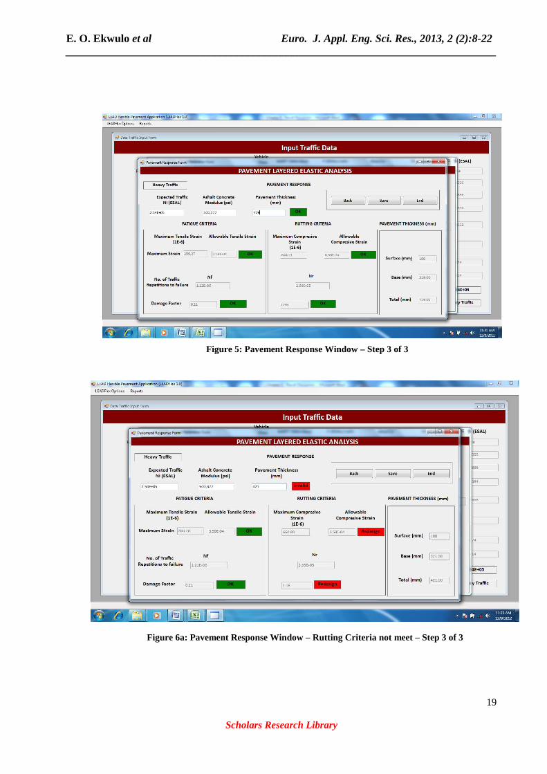
Figure 6a: Pavement Response Window – Rutting Criteria not meet – Step 3 of 3
Figure 5: Pavement Response Window – Step 3 of 3
E. O. Ekwulo et al Euro. J. Appl. Eng. Sci. Res., 2013, 2 (2):8-22 ______________________________________________________________________________
20
Scholars Research Library
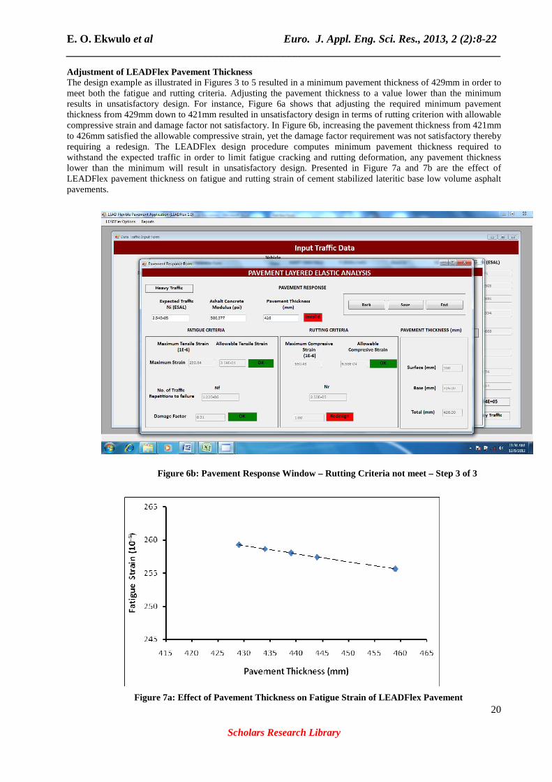
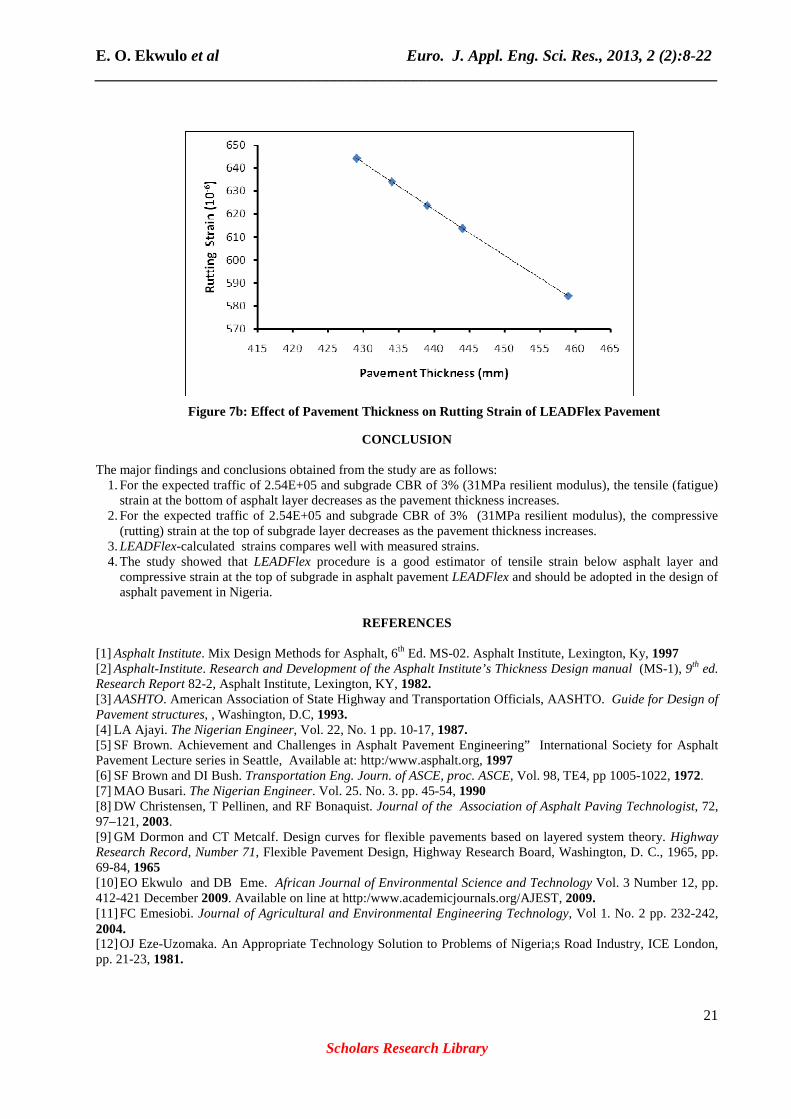
Adjustment of LEADFlex Pavement Thickness The design example as illustrated in Figures 3 to 5 resulted in a minimum pavement thickness of 429mm in order to meet both the fatigue and rutting criteria. Adjusting the pavement thickness to a value lower than the minimum results in unsatisfactory design. For instance, Figure 6a shows that adjusting the required minimum pavement thickness from 429mm down to 421mm resulted in unsatisfactory design in terms of rutting criterion with allowable compressive strain and damage factor not satisfactory. In Figure 6b, increasing the pavement thickness from 421mm to 426mm satisfied the allowable compressive strain, yet the damage factor requirement was not satisfactory thereby requiring a redesign. The LEADFlex design procedure computes minimum pavement thickness required to withstand the expected traffic in order to limit fatigue cracking and rutting deformation, any pavement thickness lower than the minimum will result in unsatisfactory design. Presented in Figure 7a and 7b are the effect of LEADFlex pavement thickness on fatigue and rutting strain of cement stabilized lateritic base low volume asphalt pavements.
Figure 6b: Pavement Response Window – Rutting Criteria not meet – Step 3 of 3
Figure 7a: Effect of Pavement Thickness on Fatigue Strain of LEADFlex Pavement
E. O. Ekwulo et al Euro. J. Appl. Eng. Sci. Res., 2013, 2 (2):8-22 ______________________________________________________________________________
21
Scholars Research Library
CONCLUSION The major findings and conclusions obtained from the study are as follows:
1. For the expected traffic of 2.54E+05 and subgrade CBR of 3% (31MPa resilient modulus), the tensile (fatigue) strain at the bottom of asphalt layer decreases as the pavement thickness increases.
2. For the expected traffic of 2.54E+05 and subgrade CBR of 3% (31MPa resilient modulus), the compressive (rutting) strain at the top of subgrade layer decreases as the pavement thickness increases.
3. LEADFlex-calculated strains compares well with measured strains. 4. The study showed that LEADFlex procedure is a good estimator of tensile strain below asphalt layer and
compressive strain at the top of subgrade in asphalt pavement LEADFlex and should be adopted in the design of asphalt pavement in Nigeria.
REFERENCES
[1] Asphalt Institute. Mix Design Methods for Asphalt, 6th Ed. MS-02. Asphalt Institute, Lexington, Ky, 1997 [2] Asphalt-Institute. Research and Development of the Asphalt Institute’s Thickness Design manual (MS-1), 9th ed. Research Report 82-2, Asphalt Institute, Lexington, KY, 1982. [3] AASHTO. American Association of State Highway and Transportation Officials, AASHTO. Guide for Design of Pavement structures, , Washington, D.C, 1993. [4] LA Ajayi. The Nigerian Engineer, Vol. 22, No. 1 pp. 10-17, 1987. [5] SF Brown. Achievement and Challenges in Asphalt Pavement Engineering” International Society for Asphalt Pavement Lecture series in Seattle, Available at: http:/www.asphalt.org, 1997 [6] SF Brown and DI Bush. Transportation Eng. Journ. of ASCE, proc. ASCE, Vol. 98, TE4, pp 1005-1022, 1972. [7] MAO Busari. The Nigerian Engineer. Vol. 25. No. 3. pp. 45-54, 1990 [8] DW Christensen, T Pellinen, and RF Bonaquist. Journal of the Association of Asphalt Paving Technologist, 72, 97–121, 2003. [9] GM Dormon and CT Metcalf. Design curves for flexible pavements based on layered system theory. Highway Research Record, Number 71, Flexible Pavement Design, Highway Research Board, Washington, D. C., 1965, pp. 69-84, 1965 [10] EO Ekwulo and DB Eme. African Journal of Environmental Science and Technology Vol. 3 Number 12, pp. 412-421 December 2009. Available on line at http:/www.academicjournals.org/AJEST, 2009. [11] FC Emesiobi. Journal of Agricultural and Environmental Engineering Technology, Vol 1. No. 2 pp. 232-242, 2004. [12] OJ Eze-Uzomaka. An Appropriate Technology Solution to Problems of Nigeria;s Road Industry, ICE London, pp. 21-23, 1981.
Figure 7b: Effect of Pavement Thickness on Rutting Strain of LEADFlex Pavement
E. O. Ekwulo et al Euro. J. Appl. Eng. Sci. Res., 2013, 2 (2):8-22 ______________________________________________________________________________
22
Scholars Research Library
[13] W Heu Kelom, and AJ. Klomp. Dynamic Testing as a Means of Controlling Pavements During and after Construction, Proceedings of the First International Conference on the Structural Design of Asphalt Pavements, pp. 667, 1962. [14] M Melhem and F Sheffield. Accelerated Testing for Studying Pavement Design and Performance. Report No. FHWA-KS-97-7. Kansas State University, Manhattan, Kansas. 2000. [15] PK Nanda. A Simplified Approach to the Estimation of Equivalent Single Axles” Proceedings, Conference on Material Testing, Control and Research, Federal Ministry of Works, pp 30-51, 1981. [16] NCHRP. Guide for mechanistic –Empirical Design of New and Rehabilitated Pavement Structures (2004). National Cooperative Highway Research Program Report No. 20-45, Transportation Research Board, National Research Council, 2004. [17] NCHRP. Evaluation of Mechanistic-Empirical Design Procedure, National Cooperative Highway Research Program, NCHRP Project 1-37A, National Research Council, Washington, D.C, 2007. [18] SA Ola. Relationship Between CBR and Static Modulus of Deformation of Stabilized Stabilized Lateritic Soils, Seventh Regional Conference for Africa on Soil Mechanics and Foundation Engineering, Accra, pp. 223-232, 1980. [19] AT Oyediran. Primary Cause of Highway Failures in South Western Nigeria and Lasting Solutions NSE Technical Transactions, Vol. 36, No. 3 pp. 54-60, 2001. [20] RN Saal and PS Pell. Fatigue of bituminous road mixes, colloid Zeitschrift, Vol. 171, No. 1, pp 61-71, 1960. [21] N Sivaneswaran, LM Piecce and JP Maheoney. Everstress Version 5.0 (Layered Elastic Analysis Program) Washington State Department of Transportation, 2001. [22] SPSS. SPSS Windows Evaluation, Release 14.00. SPSS INC, Chicago, 2005. [23] Transport and Road Research Laboratory “A Guide to the Structural Design of Pavements for New Roads”. Road Note 29, 3rd Ed. Department of Environment, HMSO, London, 1970, [24] HH Yang. Asphalt Pavement Design – The Shell Method. Proceedings, 4th International Conference on Structural Design of Asphalt Pavements, 1973. [25] Washington State Department of Transportation, WSDOT. Pavement Guide” Washington State Department of Transportation, Olympia WA, 1995.