85
DOKUZ EYLÜL UNIVERSITY GRADUATE SCHOOL OF NATURAL AND APPLIED SCIENCES SEA WATER EFFECT ON COMPOSITE PIPES SUBJECTED TO IMPACT LOADING by Murat SARI June, 2010 ĐZMĐR

DOKUZ EYLÜL UNIVERSITY
GRADUATE SCHOOL OF NATURAL AND APPLIED
SCIENCES
SEA WATER EFFECT ON COMPOSITE PIPES
SUBJECTED TO IMPACT LOADING
by
Murat SARI
June, 2010
ĐZMĐR
SEA WATER EFFECT ON COMPOSITE PIPES
SUBJECTED TO IMPACT LOADING
A Thesis Submitted to the
Graduate School of Natural and Applied Sciences of Dokuz Eylül University
In Partial Fulfillment of the Requirements for the Degree of Master of Science
in Mechanical Engineering, Mechanics Program
by
Murat SARI
June, 2010
ĐZMĐR

ii
M.Sc THESIS EXAMINATION RESULT FORM
We have read the thesis entitled “SEA WATER EFFECT ON COMPOSITE
PIPES SUBJECTED TO IMPACT LOADING” completed by MURAT SARI
under supervision of PROF. DR. RAMAZAN KARAKUZU and we certify that in
our opinion it is fully adequate, in scope and in quality, as a thesis for the degree for
Master of Science.
Prof. Dr. Ramazan KARAKUZU
Supervisor
(Jury Member) (Jury Member)
Prof.Dr. Mustafa SABUNCU
Director
Graduate School of Natural and Applied Sciences

iii
ACKNOWLEDGMENTS
First of all, I must express my sincere gratitude to my supervisor, Prof. Dr.
Ramazan KARAKUZU, for his psychological and mental support and guidance
throughout of the greatest contribution to the compilation of this study.
I also would like to express my gratitude to Prof. Dr. Onur SAYMAN, for his
technical consequential support throughout all of the study.
I would like to thank research assistants M. Emin DENĐZ, Aytaç GÖREN,
mechanical engineer Tolga DOĞAN and technician Salih EKŞĐ for their help during
experimental stages of the study.
I would like to thank TÜBĐTAK (The Scientific and Technological Research
Council of Turkey) for supporting this study under Project number 108M471.
I would like to thank thanks “Đzoreel”, “Artipol” and “HPA” firms for their
materials and instrument supports.
I wish to express my thanks to my brother students, Olgay DAĞDELEN and
Yalın AKGÜN for their direct and indirect various friendly aids.
Finally, I would like to thank my parents for their continuous loving support
throughout my all life and also I would like to my fiance for her inexhaustible
passion, patience and understanding.
Murat SARI
iv
SEA WATER EFFECT ON COMPOSITE PIPES
SUBJECTED TO IMPACT LOADING
ABSTRACT
The aim of this experimental study was to investigate the sea water effect on
fatigue behavior of composite pipes subjected to impact loads.
In this study, firstly, the general data about burst strength (load capacity) and
average life cycle of fatigue composite pipes are given. Manufacturing of vessels by
filament winding method is expressed. Schematic of a filament-winding process is
demonstrated and also materials of filament winding and applications of filament
wound products are given. Information and procedure about impact and fatigue tests
are given.
Secondly, impact tests and fatigue test results are presented. The impact tests are
performed at three different energy levels as 5J, 7.5J, and 10J at room temperature.
The impact characteristics such as peak force, maximum deflection and total
absorbed energy are listed. The mentioned impact characteristics of both conditions
(dry condition and sea water immersion) are plotted against the impact energies.
Using of load-deflection and load-time curves the impact properties of filament
wound-glass fiber reinforced plastic (FW-GFRP) pipes are discussed for both
conditions. Fatigue life cycles of FW-GFRP pipes and graphs of cycle to failure for
all test specimens are given. Damage mechanisms (modes) of composite pipes are
examined in detail.
The results obtained are evaluated and discussed by using some graphics and
images. Generally, two results are deduced. It is confirmed that impact energy brings
about reduction of the burst strength of composite pipes. Remarkable other finding is
observed that impact and burst strength values of composite pipes which are exposed
sea water (three months) are increased a bit.
Keywords: Composite pipes, Impact, Sea water immersion, Fatigue life

v
DARBELĐ YÜKLEMEYE MARUZ KOMPOZĐT BORULARDA
DENĐZ SUYUNUN ETKĐSĐ
ÖZ
Bu deneysel çalışmanın amacı, darbe hasarı sonrası deniz suyunun kompozit
boruların yorulma davranışlarına etkisini araştırmaktır.
Bu çalışmada, ilk olarak, patlama basıncı (yük kapasitesi) ve yorulma ömür
çevirimi ile alakalı genel veriler verilmiştir. Filaman sarma tekniği ile kapların
üretimi anlatılmıştır. Şematik filaman sarma süreçleri resmedilmiştir. Filaman sargı
malzemeleri ve filaman sargılı ürünlerin uygulamaları hakkında bilgiler verilmiştir.
Darbe ve yorulma deneyi hakkında bilgi ve prosedürler aktarılmıştır.
Đkinci olarak, darbe ve yorulma test sonuçları sunulmuştur. Üç ayrı enerji
seviyesine (5J, 7.5J ve 10J) sahip olan darbe testleri oda sıcaklığında
gerçekleştirilmiştir. Darbe maksimum kuvvet, maksimum çökme ve toplam absorbe
edilen enerji gibi darbe karakteristikleri listelenmiştir. Kuru ortam ve deniz suyu
ortamında bulunan numunelerin söz edilen darbe karakteristik eğilimleri uygulanan
darbe enerjilerine göre grafiğe dökülmüştür. Yük-çökme ve yük-zaman eğrileri
kullanılarak cam filaman sargılı kompozit boruların darbe özellikleri her iki ortam
için yorumlanmıştır. Cam filaman sargılı kompozit boruların yorulma ömür
çevirimleri ve tüm numuneler için çevrim-hasar fazı grafikleri verilmiştir. Kompozit
boruların hasar mekanizmaları (modları) ayrıntılı olarak incelenmiştir.
Elde edilen sonuçlar çeşitli resim ve grafikler yardımıyla değerlendirilmiş ve
özgün çıkarımlar yapılmıştır. Genel olarak iki sonuca ulaşılmıştır. Darbe enerjisinin
kompozit boruların patlatma mukavemet değerlerinde düşüşe neden olduğu
doğrulanmıştır. Dikkate değer diğer bulgu deniz suyuna üç ay maruz bırakılan
kompozit boruların darbe ve patlatma mukavemetlerinde bir miktar artış
gözlemlenmesidir.
Anahtar sözcükler: Kompozit borular, Darbe, Deniz suyu emmesi, Yorulma ömrü

CONTENTS
Page
M.Sc THESIS EXAMINATION RESULT FORM .............................................. ii
ACKNOWLEDGMENTS ................................................................................... iii
ABSTRACT ....................................................................................................... iv
ÖZ ....................................................................................................................... v
CHAPTER ONE - INTRODUCTION .............................................................. 1
1.1 General View ............................................................................................. 1
1.2 Outline of the Thesis .................................................................................. 3
CHAPTER TWO - COMPOSITE PRESSURE VESSELS AND MANUFACTURING ......................................................................................... 5
2.1 Composite Pressure Vessels ....................................................................... 5
2.1.1 Structure of Composite Pressure Vessels ............................................. 7
2.2 Filament Winding ...................................................................................... 8
2.2.1 Materials of Filament Winding .......................................................... 10
2.3 Background .............................................................................................. 13
2.3.1 The Impact Damage on Composite Pipes ........................................... 13
2.3.2 The Burst of Composite Pipes ........................................................... 19
2.3.3 The Burst of Composite Pipes After Damaged ................................... 23
2.3.4 The Effect of Water Immersion on Composites ................................. 30
CHAPTER THREE - EXPERIMENTAL SETUP ......................................... 36
3.1 Production FW-GFRP pipes ..................................................................... 36
3.2 Sea Water Simulation ............................................................................... 38
3.3 Impact Testing ......................................................................................... 39
3.3.1 Design of V-block ............................................................................. 43
3.4 Fatigue Testing......................................................................................... 44
3.4.1 Experimental Setup ........................................................................... 45

CHAPTER FOUR - RESULTS AND DISCUSSIONS ................................... 48
4.1 Impact testing ........................................................................................... 48
4.2 Fatigue Testing......................................................................................... 57
4.2.1 Fatigue Observations ......................................................................... 67
CHAPTER FIVE - CONCLUSIONS AND RECOMMENDATIONS .......... 68
5.1 Conclusions.............................................................................................. 68
5.1.1 Results of the Impact Tests ................................................................ 68
5.1.2 Results of the Fatigue Tests ............................................................... 68
5.1.3 Results of the Sea Water Effect ......................................................... 69
5.2 Recommendations .................................................................................... 69
REFERENCES ................................................................................................ 71

1
CHAPTER ONE
INTRODUCTION
1.1 General View
Fiber reinforced composites become important increasingly in submarine- aircraft
vehicles, automotive, sport equipments, weapon-armor industry and so on, this is
because fiber reinforced composites are of high specific strength and stiffness.
Pressure vessels, gas and liquid transfer pipes, cryogenic gas tanks, rocket motor
cases and launchers manufactured by filament winding methods and loaded by
internal pressure are widely used in advanced technologies based on their light-
weight, high mechanical properties, damage tolerance, good corrosion resistance and
low cost. Variety of parameters for availability is existed for filament wound fiber
reinforced plastic (glass; FW-GFRP, carbon; FW-CFRP, aramid; FW-AFRP) pipes
such as optimum winding angles, number of layers, volume fractions of fiber,
internal pressure and environmental conditions which affect the strength and some
other properties (Young modulus, shear modulus, toughness etc. ) of the pipes.
Background shows that, in generally optimization of composite vessels are done by
changing the above-mentioned parameters are investigated.
The FW pipes may be subjected to impact loads due to dropping, pulsating,
knocking and/or rough handling. These impact loads cause interlaminar delamination
results in reduction in mechanical properties like compression, tension, buckling
strength and stiffness of fiber reinforced composites, even the damages are not
visible. In this point of view, it is necessary to clarify the strength reduction
mechanism after impact and to improve the impact resistance. Also, surface cracks
which exist in mentioned composite structures can lead to catastrophical failures,
especially in corrosive and cyclic loading conditions.
There are too many investigations, handbooks and articles about composite
material. In this study, information about fundamentals of composite materials has

2
not been acquainted. Therefore the following references are put account for them;
Jones R. M. (1999), Mazumdar, S. K. (2002), Mallick, P.K. (2007).
Mightily and adequate studies are done about mechanical behavior of the
composite plates. They focused mainly on the mechanical properties like tensile,
fatigue, fracture and impact characteristics of the GFRP materials. At the same time,
many researchers worked on identifying the effects of impact, consequent
delamination, and material properties such as specific energy absorption, maximum
peak load, maximum contact time, compressive strength and so on.
On the other hand, it is seen that the effect of dynamic inner pressure (fatigue) on
tubes was studied only to a limited extent in recent years. A review of the literature
revealed a number of studies focused on pipes but there are fewer investigations
about the fatigue and fatigue behavior of fiber reinforced pipes with surface damage
(impact, crack etc.). These experimental studies are conducted for several parametric
(crack size, crack orientation, exposed matter type etc.) applications.
Experimental studies were main point of this research that aimed to investigate the
fatigue behavior of composite pipes after impact damage. The thesis also focuses on
the sea water effect failure analysis of composite pipes by experiment. Failure phases
of composite pipes are extensively studied.
So that the study generally consist from following three phases experimental test;
1- Expose the specimens 3 months in sea water,
2- Perform various impact loading,
3- Apply dynamic inner pressure (fatigue).
Hydrostatic burst tests were conducted using a self designed an in-house and
fabricated HPA corporation. The impact test characteristic was studied by using
Ceast-Fractovis Plus impact tester.
3
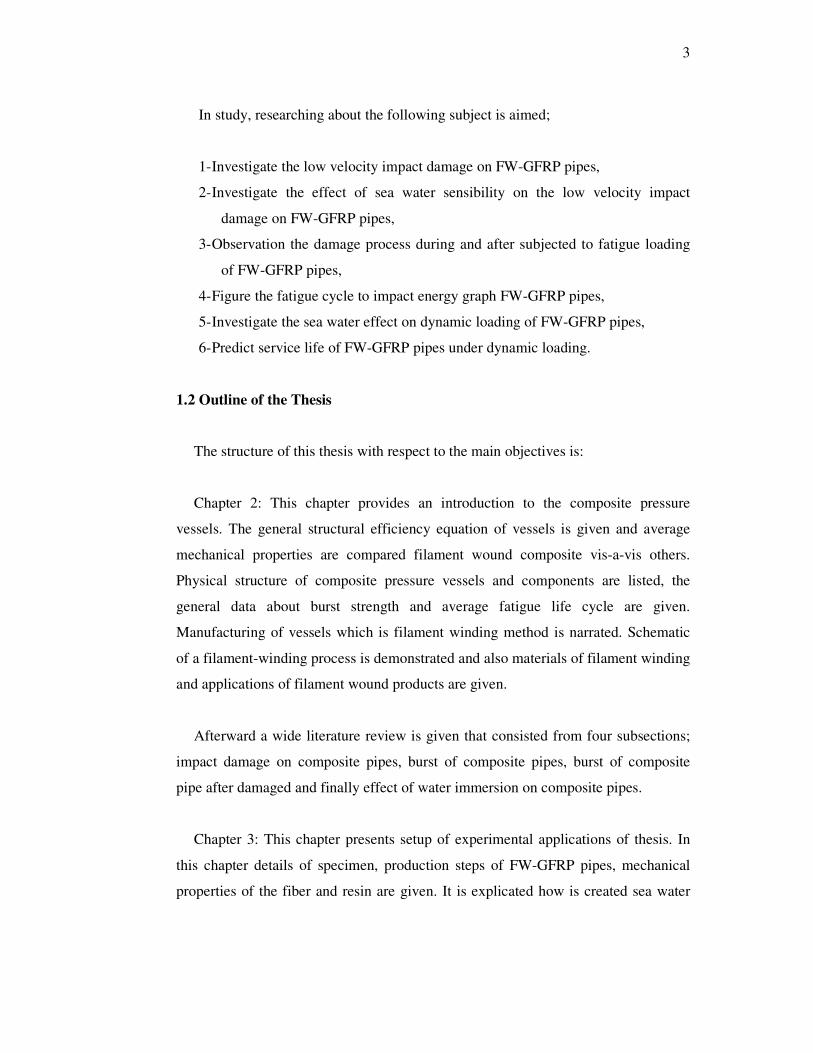
In study, researching about the following subject is aimed;
1- Investigate the low velocity impact damage on FW-GFRP pipes,
2- Investigate the effect of sea water sensibility on the low velocity impact
damage on FW-GFRP pipes,
3- Observation the damage process during and after subjected to fatigue loading
of FW-GFRP pipes,
4- Figure the fatigue cycle to impact energy graph FW-GFRP pipes,
5- Investigate the sea water effect on dynamic loading of FW-GFRP pipes,
6- Predict service life of FW-GFRP pipes under dynamic loading.
1.2 Outline of the Thesis
The structure of this thesis with respect to the main objectives is:
Chapter 2: This chapter provides an introduction to the composite pressure
vessels. The general structural efficiency equation of vessels is given and average
mechanical properties are compared filament wound composite vis-a-vis others.
Physical structure of composite pressure vessels and components are listed, the
general data about burst strength and average fatigue life cycle are given.
Manufacturing of vessels which is filament winding method is narrated. Schematic
of a filament-winding process is demonstrated and also materials of filament winding
and applications of filament wound products are given.
Afterward a wide literature review is given that consisted from four subsections;
impact damage on composite pipes, burst of composite pipes, burst of composite
pipe after damaged and finally effect of water immersion on composite pipes.
Chapter 3: This chapter presents setup of experimental applications of thesis. In
this chapter details of specimen, production steps of FW-GFRP pipes, mechanical
properties of the fiber and resin are given. It is explicated how is created sea water

4
simulation and performed impact and fatigue testing. Also detailed figures of
experimental setup, equipments and apparatus are given.
Chapter 4: This chapter hosts the main product of the study what the results and
discussions. In this chapter, the impact characteristics such as peak force, maximum
deflection and total absorbed energy are listed and its trends together comparison of
composite pipes both dry and water immersed conditions, against the impact
energies. Using of load-deflection and load-time curves the impact properties of FW-
GFRP pipes are commented for both dry and sea water immersed conditions.
Cycles of fatigue life of FW-GFRP pipes and graphs of cycle to failure phases of
fatigue life of all test specimens are given finally fatigue observations of tubes is
listed.
Chapter 5: in this chapter, summation of the results of the impact tests, the
fatigue tests and the sea water effect are given. Then related with experiment
recommendations is presented.

5
CHAPTER TWO
COMPOSITE PRESSURE VESSELS AND MANUFACTURING
2.1 Composite Pressure Vessels
Pressure vessels have long been manufactured by filament winding. Pressure
vessels appear to be simple structures, but they are among the most difficult to
design. Filament-wound composite pressure vessels have found widespread use not
only for military use but also for civilian applications. This technology previously
developed for the military’s internal use was adapted to civilian purpose and
following this, extended to the commercial market. Applications include breathing
device, such as self-contained breathing apparatuses used by fire-fighters and other
emergency personnel, scuba tanks for divers, oxygen cylinders for medical and
aviation cylinders for emergency slide inflation, opening doors or lowering of
landing gear, mountaineering expedition equipment, paintball gas cylinders, etc. .
A potential widespread application for composite pressure vessels is the
automotive industry. Intensions for reducing emissions leads the conversion to
Compressed Natural Gas (CNG) fuelled vehicles worldwide. The main aim of the
industry here is the attempt to replace fuel oils with natural gas or hydrogen as the
energy supply in vehicles for air quality improvements and reduce global
warming. The successful application of these fuels in vehicles may be achieved by
fuel cells in concert with hydrogen gas storage technologies. One of the missing
milestones here is the inadequacy of the vehicle range between refueling stops.
Other important parameters in these applications are weight, volume and cost of
the containment vessel (Onder, 2007).
Filament-wound composite pressure vessels developed from high strength and
high modulus to density ratio materials offer significant weight savings over
conventional all-metal pressure vessels for the containment of high pressure gases
and fluids. The structural efficiency of pressure vessels is defined as:

6
W
VP =e b (2.1)
where; Pb: Burst pressure, V: Contained volume, W: Vessel weight
The structural efficiencies of all-metal pressure vessels change from 7.6*106 to
15.2*106 mm while filament wound composite vessels have efficiencies in the
range from 20.3*106 to 30.5*106 mm. This can be stated as the structural
efficiencies of composite pressure vessels are better than all-metal pressure
vessels of similar volume and pressure. Also some other properties of tubes are
compared below in Table 2.1 (Onder, 2007).
Table 2.1 Property comparisons: Filament wound composite vis-a-vis others (C-K Composites)
Material * Density (g/cc)
Tensile Strength (MPa)
Tensile Modulus
(MPa)
Specific Tensile Strength (103 m)
Filament Wound Composite 1.99 1034 31.02 52.96
Aluminium 7075-T6 2.76 565 71.01 20.87
Stainless Steel -301 8.02 1275 199.94 16.20
Titanium Alloy (Ti-13 V-12 Cr-3 Al) 4.56 1275 110.3 28.50
*For unidirectional composites, the reported modulus and tensile strength values are measured in the direction of fibers.
Composite vessels with very high burst pressures (70-100 MPa) are in service
today in the aerospace industry. Vessels with burst pressure between 200 – 400
MPa are under investigation and such containment levels were achieved in the late
1970’s through mid 1980’s. Further researches must be made for the design of
advanced ultra-high pressure composite vessels (Onder, 2007).
A maximum pressure of 35 MPa is permitted under current regulations, 21 MPa is
a standard vehicle refueling system’s nominal output pressure for civilian
applications. Higher pressures are not yet approved for use on public roads or
7
commercial aircraft. This implies a great need for advancement in composite
pressure vessel technology (Onder, 2007).
2.1.1 Structure of Composite Pressure Vessels
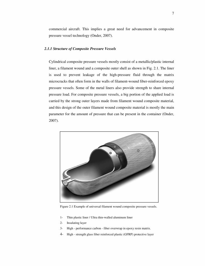
Cylindrical composite pressure vessels mostly consist of a metallic/plastic internal
liner, a filament wound and a composite outer shell as shown in Fig. 2.1. The liner
is used to prevent leakage of the high-pressure fluid through the matrix
microcracks that often form in the walls of filament-wound fiber-reinforced epoxy
pressure vessels. Some of the metal liners also provide strength to share internal
pressure load. For composite pressure vessels, a big portion of the applied load is
carried by the strong outer layers made from filament wound composite material,
and this design of the outer filament wound composite material is mostly the main
parameter for the amount of pressure that can be present in the container (Onder,
2007).
Figure 2.1 Example of universal filament wound composite pressure vessels.
1- Thin plastic liner / Ultra thin-walled aluminum liner
2- Insulating layer
3- High - performance carbon - fiber overwrap in epoxy resin matrix.
4- High - strength glass fiber reinforced plastic (GFRP) protective layer
8
In the following there are some comments for production process of composite
pressure vessels and internal pressure (static and dynamic).
The winding is done on the liner, which also serves as a mandrel. The winding
tension and the subsequent curing action create compressive stresses in the liner
and tensile stresses in the fiber reinforced epoxy overwrap. After fabrication, each
vessel is pressurized with an internal proof pressure (also called the ‘sizing’
pressure) to create tensile yielding in the metal liner and additional tensile stresses
in the overwrap. When the proof pressure is released, the metal liner attains a
compressive residual stress and the overwrap remains in tension. In service, the
metal liner operates elastically from compression to tension and the composite
overwrap operates intension mode (Mallick, 2007).
The internal pressure generates tensile normal stresses in the tank wall in both the
hoop (circumferential) and axial directions. The hoop stress for the most part is
twice the axial stress. The tanks are designed to withstand a maximum (burst)
pressure three times the operating pressure. Selected numbers of tanks are tested
up to the burst pressure after subjecting them to 10,000 cycles of zero to operating
pressure and 30 cycles of zero to proof pressure. Leakage before catastrophic
rupture considered the desirable failure mode during this pressure cycling. Other
major qualification tests for the air-breathing tanks are drop impacts, exposure to
high temperatures in the pressurized condition, and exposure to direct fire
(Mallick, 2007).
2.2 Filament Winding
Filament winding is a fabrication technique for creating composite material
structures. The process involves winding filaments under varying amounts of tension
over a male mould or mandrel. The mandrels rotates while a carriage moves
horizontally, laying down fibers in the desired pattern. In Figure 2.2 schematic of a
filament-winding process is shown. The most common filaments are carbon or glass
fiber and are coated with synthetic resin as they are wound. Once the mandrel is

9
completely covered to the desired thickness, the mandrel is placed in an oven to
solidify (set) the resin. Once the resin has cured, the mandrel is removed, leaving the
hollow final product.
Figure 2.2 Schematic of a filament-winding process (Mallick, 2007).
Filament winding is well suited to automation, where the tension on the filaments
can be carefully controlled. Filaments that are applied with high tension results in a
final product with higher rigidity and strength; lower tension results in more
flexibility. The orientation of the filaments can also be carefully controlled so that
successive layers are plied or oriented differently from the previous layer. The angle
at which the fiber is laid down will determine the properties of the final product. A
high angle "hoop" will provide crush strength, while a lower angle pattern (known as
a closed or helical) will provide greater tensile strength.
The mechanical properties of the helically wound part depend strongly on the
wind angle, as shown in Figure 2.3.

10
Figure 2.3 Mechanical property variations in a filament-wound part as a function of wind angle (Mallick, 2007).
2.2.1 Materials of Filament Winding
Glass fiber is the fiber most frequently used for filament winding, carbon and
aramid fibers are also used. Most high strength critical aerospace structures are
produced with epoxy resins, with either epoxy or cheaper polyester resins being
specified for most other applications. The ability to use continuous reinforcement
without any breaks or joins is a definite advantage, as is the high fiber volume
fraction that is obtainable, about 60% to 80%. Only the inner surface of a filament
wound structure will be smooth unless a secondary operation is performed on the
outer surface. The component is normally cured at high temperature before
removing the mandrel. Finishing operations such as machining or grinding are not
normally necessary (Filament winding, wikipedia.org).
In Figure 2.4, some filament wound parts and in Table 2.2, applications of
filament wound products are given.

11
Figure 2.4 Filament wound parts (Mazumdar, 2002).

12
Table 2.2 Filament wound products: Applications and Resin systems (C-K Composites)
Industry Typical Application Typical Resin Systems
Corrosion •Underground Storage Tanks • Aboveground Storage Tanks
Polyester (Ortho- and Isophthalic), Vinyl Ester
• Piping Systems • Stack Liners • Ducting Systems
Polyester (Ortho- and Isophthalic), Vinyl Ester, Epoxy, Phenolic
Oilfield • Piping Systems • Drive Shafts • Tubular Structures
Epoxy, Phenolic
Paper and Pulp • Paper Rollers • Piping Systems • Ducting Systems
Vinyl Ester, Epoxy
Infrastructure and Civil Engineering
• Column Wrapping • Tubular Support Structures • Power Poles • Light Standards
Polyester (Ortho- andIso-phthalic), Vinyl Ester, Epoxy
Commercial Pressure Vessels
• Water Heaters • Solar Heaters • Reverse Osmosis Tanks • Filter Tanks • SCBA (Self-Contained Breathing Apparatus) Tanks • Compressed Natural Gas Tanks
Polyester (Ortho- and Iso-phthalic), Vinyl Ester, Epoxy
Aerospace • Rocket Motor Cases • Drive Shafts • Launch Tubes • Aircraft Fuselage • High Pressure Tanks • Fuel Tanks
Epoxy, Bismaleimide (BMI), Phenolic, Vinyl Ester
Marine • Drive Shafts • Mast and Boom Structures
Epoxy
Sports and Recreation
• Golf Shafts • Bicycle Tubular Structures • Wind Surfing Masts • Ski Poles
Epoxy

13
2.3 Background
Many studies on GFRP degradations are reported in the literature that includes
corrosion, electromagnetic effects, fatigue, water immersion, fire, impact damage,
weathering, temperature, rain erosion etc. Among them, three major effects (impact
damage, fatigue, water immersion) is investigated on that could significantly degrade
GFRPs are.
This literature review has consisted from four subsections; the impact damage on
composite pipes, the burst of composite pipes, the burst of composite pipes after
damaged and finally the effect of water immersion on composite pipes. So that
background of this thesis divided four subheadings.
2.3.1 The Impact Damage on Composite Pipes
Composite materials are very sensitive to out-of-plane loading (i.e., loading
transverse to plies or reinforcement) because they are much weaker in the
thickness direction than in the plane of lamination. Consequently, composite
materials subjected to transverse impact may suffer significant damage, resulting
in deterioration of its overall load-carrying capacity. The response of composite
materials to these impact loadings is complex, as it depends on the structural
configuration as well as the intrinsic material properties. Further, it depends on the
material, geometry, and velocity of the impactor (Naik, 2005).
Each plays an important role in characterizing the overall effect of transverse
impact. The various forms of damage modes possible under impact loading range
from non-visible or barely visible to penetration of the impactor. Low velocity
impacts may not cause any visible damage on the laminate but may cause internal
damage in the form of matrix cracking, delamination, and/or fiber cracking inside
the laminate. This may lead to significant reduction in strength. Stiffness
reductions are also possible but not generally dramatic. A common example of
low velocity impact is the accidental dropping of a tool on the composite

14
component or structure during manufacturing, service, or maintenance. Generally,
impact with impactor speeds less than 100 m/s are classified as low velocity
impact. But there are several other definitions of low velocity impact, with no
universal agreement. Sometimes low velocity impact is used in the context of low
energy impact, i.e., less than 136 J (100 ft-lb). Low velocity impact normally
involves deformation of the entire structure during the contact duration of the
impactor, and this situation is considered quasi-static with no consideration of the
stress waves that propagate between the impactor and the boundary of the
impacted component. On the other hand, high velocity or hypervelocity impacts
involve impactor speeds greater than 1 km/s. This is sometimes also referred to a
situation where complete penetration of target (i.e., composite structure) occurs.
Usually, the deformation of the composite structure in high velocity impact is
localized in a small zone surrounding the contact area during the duration of
contact with the impactor (Naik, 2005).
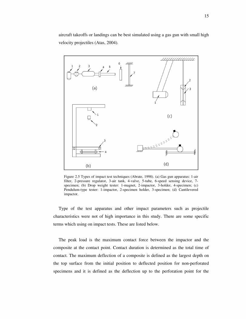
To simulate actual impact by a foreign object, a number of impact test apparatuses
are suggested: Gas gun apparatus, drop weight tester, cantilevered impactor, and
pendulum-type tester. In his book “Impact on Composite Structures”, Abrate
(1998), has introduced the articles describing these impact test apparatus. Of these
apparatus, drop weight tester, and gas gun are used by most investigators.
Although much detail of the actual test apparatus may differ, schematic
illustrations of these apparatuses including main parts are given in Figure 2.5
(Atas, 2004).
In experimental studies it is attempted to replicate actual situations under controlled
conditions. Even if the initial impact energies of the projectiles are exactly the same, a
smaller mass with higher initial velocity and a large mass with low velocity may
cause different amount of damage and damage modes. Therefore, type of
apparatus chosen and impact factors affecting the response of the structure, such
as velocity of the projectile, gain high importance in experiments. For example,
dropping of tools on the structures during maintenance operations can be
simulated by drop weight tester while flying of debris on the runway during
15
aircraft takeoffs or landings can be best simulated using a gas gun with small high
velocity projectiles (Atas, 2004).
Figure 2.5 Types of impact test techniques (Abrate, 1998). (a) Gas gun apparatus: 1-air filter, 2-pressure regulator, 3-air tank, 4-valve, 5-tube, 6-speed sensing device, 7-specimen; (b) Drop weight tester: 1-magnet, 2-impactor, 3-holder, 4-specimen; (c) Pendulum-type tester: 1-impactor, 2-specimen holder, 3-specimen; (d) Cantilevered impactor.
Type of the test apparatus and other impact parameters such as projectile
characteristics were not of high importance in this study. There are some specific
terms which using on impact tests. These are listed below.
The peak load is the maximum contact force between the impactor and the
composite at the contact point. Contact duration is determined as the total time of
contact. The maximum deflection of a composite is defined as the largest depth on
the top surface from the initial position to deflected position for non-perforated
specimens and it is defined as the deflection up to the perforation point for the

16
perforated specimens. The absorbed energy is the energy consumed between the
impactor and the specimen through the formation of damage and friction.
Currently, however, increasing use is being made of instrumented impact tests
with drop weight impact testers to characterize the low velocity impact of
composite structures. This is usually done on drop weight impact machines, where
the striker is instrumented to measure the applied load. These machines have
means of measuring displacement or acceleration. Thus the history of the load,
displacement, and acceleration during the impact event is recorded, and these can
be converted to give impact load-time and impact energy-time histories. From
these, features such as peak load and absorbed energy can be related to fracture
processes occurring in the material. A typical load history in an impact test is
schematically shown in Figure 2.6. The load-time history can be divided into two
distinct regions, a region of fracture initiation and a region of fracture
propagation. As the load increases during fracture initiation phase, elastic strain
energy is accumulated in the specimen and no gross failure takes place; but failure
mechanisms on a microscale for example, microbuckling of the fibers on the
compression side or debonding at the fiber-matrix interface are possible. When a
critical load is reached at the end of the initiation phase, the composite specimen
may fail either by a tensile or a shear failure depending on the relative values of
the tensile and interlaminar shear strengths. At this point the fracture propagates
either in a catastrophic "brittle" manner or in a progressive manner continuing to
absorb energy-at smaller loads (Naik, 2005).

17
Figure 2.6 Typical load history during impact test. (Shyr & Pan, 2003)
The total impact energy, Et as recorded on the impact machine or on the energy-
time curve on the oscilloscope is thus the sum of the initiation energy, Ei and
propagation energy, Ep. A high-strength brittle material which has a large
initiation energy but a small propagation energy and a low-strength ductile
material which has a small initiation energy but a large propagation energy-may
have the same total impact energy (Naik, 2005).
It has being seen that impact on tubes was studied only to a limited extent in
recent years. There were investigations about burst strength reduction after surface
damage (impact, indentation or surface crack) on FW-GFRP, FW-CFRP and FW-
AFRP pipes (with/without “liner”).
Some researchers worked on identifying the effects of impact, consequent
delamination, and material properties such as specific energy absorption, maximum
peak load, maximum contact time, compressive strength and so on.
Doyum & Altay (1997) focused on the detection of damage after low velocity
transverse impact loading on thin FW-GFRP (E- and S-glass) pipes experimentally.
They used visual inspection and post emulsified fluorescent penetrant systems for
damage detection and presented types and characteristics of defects.

18
Karbhari, Haller, Falzon & Hersberg (1999) investigated post-impact crush of
FW-GFRP, FW-CFRP, FW-AFRP and hybrid pipes which were different layer. They
showed that impact damage causes a reduction in the specific energy absorption of
FW pipes.
Zou, Reid, Li & Soden (2002) developed a new model for progressive
interlaminar delamination of laminated composites (FW-GFRP). They used a stress-
based failure criterion for estimation of delamination initiation and fracture
mechanics approach for propagation of delamination. In addition, this analysis has
included matrix cracking which is significant intralaminar damage mode. They
determined deformation and delamination of laminated composite structures with
finite element analysis (FEM). Test specimens had two orientations and two radiuses.
Results of the studies on mesh size of the FEM model showed that even relatively
coarse mesh size gives enough exactly results. Experimental and FEM results were
accorded. Hereby, it has being seen Zou et al.’s results are available real structural
applications.
Chib (2003) studied on simulating the response of low velocity impact test on
FW-CFRP pipes with finite element software LS-Dyna. In addition, parametric
studies such as impactor velocity, lay-up configurations and boundary conditions of
composite pipe etc. which affect the impact damage process were investigated. The
model of impact test was illustrated and the mentioned parametric test results were
shown up. The result of parametric (numeric) analysis was compared with
experimental results. Study of Chib verified the validity and effectiveness of finite
element simulation, because results of simulation had great similarity of
experimental test and predicted good simulation.
Changliang, Mingfa, Wei & Haoran (2006) studied on low velocity impact kinetic
theory for the composite hybrid which is laminated with metal liner vessel. FEM is
used to investigate the impact response of composite pipe with and without internal
pressure and predict their damage distributions during and after impact. They
19
considered the damage styles-damage distributions of different impact velocities,
geometric and material nonlinearities and the effect of contact in the analysis. They
noticed that the impact damage extent for composite FW vessel with internal
pressure is more severe than that without internal pressure under low velocity impact
case with same kinetic energy.
Tarfaoui, Gning, Davies & Collombet (2007) investigated on dynamic response
and damage characteristics of composite pipes. They aimed at improvement of
understanding the scale effects on the behavior of composite tubular structure for the
design of underwater equipment. With the results of the test, they commented that
“Although the damage is of comparable nature for all the tubes, it was necessary to
establish particular laws of similitude in order to predicted the damage of a model
cylinder from that of the prototype and vice versa”. The tests show that the response
of the structure has the primary importance in establishing the balance between
elastic deformation and local damage development.
Secondly, Tarfaoui, Gning & Hamitouche (2008) investigated finite element
analysis of static and dynamic tests on thick FW-GFRP pipes to improve the long-
term integrity of composite structures for underwater applications. The study consists
of two parts. First part is the validation of elastic properties and identification of
damage initiation and its development in dynamic tests and second part is an impact
model, including material property degradation, used for damage prediction.
Analytical models and finite element analysis are presented on text. The study
showed that there is a strong relationship between the structure and material. They
have expressed that it is important to control the influence of the conditions of
development on the limiting values of material.
2.3.2 The Burst of Composite Pipes
Hydrostatic testing is universally known and accepted as a means of
demonstrating the fitness of a pressurized component for service. After a test, a
pipeline or pressure vessel can be expected to safely contain its intended operating

20
pressure. The confidence level that a pipeline or pressure vessel is fit for safe
service increases as the ratio of test pressure to operating pressure increases. This
highly beneficial aspect of hydrostatic testing applies not only to a new
component to be placed in service for the first time. A similar benefit accrues to
an in-service component if that component is taken out of service after a period of
time and subjected to a hydrostatic test. A “revalidation” test of the latter type
assures either that no significant time dependent deterioration of the component
has taken place or that any segment that is significantly degraded will be revealed
and eliminated (Naik, 2005).
A test reveals weaknesses by causing ruptures or leaks; it does not indicate, for
example, other areas where active corrosion may be taking place. A limitation that
has both technical and economic implications is that a level of test pressure to
operating pressure sufficient to generate high confidence may result in numerous test
breaks or leaks. Repeated test failures may actually reduce confidence in the final
margin of safety demonstrated by the test, and such failures will certainly add
significantly to the cost of the test and the time out of service.
The pressure required to result in such a failure is known as the 'burst pressure'.
Actual pipe samples are pressurized with water as the internal medium and either air
or water as the external medium. The internal pressure in the pipe samples results in
both an axial and a hoop stress. As the hoop stress is twice the axial stress, it is the
stress in the hoop direction that results in failure. The hoop stress is given:
t
Pr =σ h
(2.2)
2t
Pr =σ a (2.3)
where; σh: Hoop stress, σa: Axial stress, P: Inner pressure, r: Radius, t= Thickness

21
In the literature, the optimum winding angle for filament wound composite
pressure vessels is given as 54.74o by netting (meshing-optimize) analysis. ….
Here, it is clear that the more the fiber orientation is changed from 55º, the more
the first-ply failure pressure drops (Yaylagan, 2010).
Sun, Du & Wang (1999) investigated on solid-rocket motor cases which are a
kind of composite structure by using the nonlinear FEM. They have worked up to
detect the effects of material performance and geometrical nonlinearity on the
relative loading capacity of the dome. So, they have calculated the stresses and the
bursting pressure of aforementioned vessel. From the view point of burst, the design
method from the analogous case to its real one is not rational. Because in the model I
case, the conclusion obtained was contrary to that for the model II case without
skirts. They decided that all affecting factors should be considered synthetically to
obtain the optimum structure.
Chang (2000) studied via the first-ply failure strength on symmetrically laminated
composite pressure vessels with various material properties, radius-to-thickness
ratios, and different numbers of layers subjected to uniform internal pressure loads
by experimental and analytical approaches. Optimal angle-ply orientations for
maximum stiffness were investigated. A comparison between the experimental
approaches and the analytical methods was made to demonstrate the suitability of the
failure criteria in predicting first-ply failure strength. In particular, the Hill criterion
can predict first-ply failure pressure load with error around 1%.
Kim, Kang, Hong & Kim (2005) aim to establish an optimal design method of
FW structures under internal pressure. In this research, the semi-geodesic path
algorithm was used to calculate possible winding patterns taking into account the
windability and slippage between the fiber and the mandrel surface. In addition,
progressive failure analyses were performed to predict the behavior of FW structures
on ABAQUS. In particular, suitable element types and failure criteria for FW
structures were studied. Finally, the developed design code was applied to a
symmetric composite pressure vessel for verification.
22
Zheng & Liu (2008) concentrates on a theoretical model of the composite
cylindrical laminates under internal pressure and thermal residual stress. The
theoretical model based on the last ply failure criterion, a solution algorithm is
further presented to explore the damage evolution and the burst strength of the
structure. Effects of the winding angle and number of the composite layers as well as
the thermal residual stress are explored. They calculated burst strengths and also
compared with the experimental results hence the calculated burst strengths are in
good agreement with the experimental results. The tests show that the thermal effect
increases the radial, hoop and axial stresses in the winding layers, but decreases the
hoop and axial stresses in the liner. Secondly, with increasing winding angle, the
radial displacement and shear–stress decrease, but the radial stress increases.
Khalid, Hamed & Sapuan (2007) is investigated bursting pressure and the
carrying capacity of basic plastic tubes, composite tubes and reinforced plastic tubes
under internal pressure. They exposed of the effect of the material type as filament
winding and woven roving and the effect of number of layers by experimentally.
Onder, Sayman, Dogan & Tarakcioglu (2009) examined on the influences of
temperature and winding angle on FW-GFRP pipes for increasing the maximum
burst pressure. Burst pressure of FW composite pressure vessels under alternating
pure internal pressure was investigated. The hygrothermal and other mechanical
properties were measured on E-glass–epoxy composite flat layers. Some analytical
and experimental solutions were compared with the finite element solutions about
verifying the optimum winding angles. Finally they appointed that the burst pressure
of the composite pressure vessels varies at high temperatures, since the strength of
the composite material decreases and thermal stresses occur at the high temperatures.
In addition, Onder, (2009) is proved that related production steps of this
composite pressure vessel design approximately 20ºC application environment as the
best application temperature value.
23
Velosa, Nunes, Antunes, Silva & Marques (2009) investigated on FW-GFRP
vessels with thermoplastic liner in their article which is part of a larger study
concerning the development of a new generation of FW composite vessels to be
applied on the storage of industrial uncompressed fluids under pressure. They used
FEM to predict the mechanical behavior of pressure vessels. Finally, prototype
pressure vessels were produced and submitted to pressure tests in similar conditions
to those used in the FEM simulations. Experimental results obtained on the produced
composite prototype vessels under internal pressure test confirmed the burst pressure
values obtained from FEM calculations.
Xu, Zheng & Liu (2009) studied on parametric finite element model of the
cylindrical part of composite hydrogen vessel (FW-CFRP with Al liner) to explore
the non-linear stress–strain relationship and the final failure. They aimed to find the
progressive damage and failure properties of mentioned composite structures with
increasing internal pressure. The failure pressures (for different failure criteria) are
compared with the experimental burst pressure of composite hydrogen storage
vessels. By comparison, the failure pressure using the proposed FEM’s are in
agreement with the experimental burst pressure of composite vessel. However, the
Tsai–Wu failure criterion leads to most accurate failure pressure among all failure
criterions.
2.3.3 The Burst of Composite Pipes After Damaged
Tarakcioglu, Akdemir & Avci (2001) investigated on the effect of surface cracks
on strength for FW-GFRP pipes with analytically and experimentally. They set the
specimens three different orientations with surface crack which have several notch-
aspect ratios and notch-to-thickness ratios in the axial direction. They determined
critical stress intensity factors and compared the strength values of pipes with surface
cracks are with internal pressure test results and theoretical results.
Curtis, Hinton, Li, Reid & Soden (2000) investigated the damage, deformation
and residual burst strength of FW-GFRP pipes subjected to impact/quasi-static
24
indentation numerically and experimentally. They found that the behaviors of pipes
subjected to quasi-static and low velocity impact loading tests were same.
Experimental strain measurements in quasi-static indentation tests showed a large
degree of redistribution of strain with increasing deflection which resulted in local
buckling failure away from the indentation point. Damage in the form of matrix
cracking resulted from low energy indentation but did not reduce the residual burst
strength of the pipe. Low speed impacts caused the pipes to fail by local axial shell
buckling, leading to local delamination and fracture some distance away from the
indenter. That failure reduced the residual burst strength by about 60% from 10 to 4
MPa.
Naik (2005) realized great experimental priming on his master thesis that involved
many different effects of environmental conditions such as sea water immersion, dry
heat, salt spray, humidity and impact on the burst pressure performance of the glass
fiber reinforced thermoset pipes (glass-epoxy and glass vinylester). He calculated
and illustrated the failure pressures for different impact energies and residual
pressure strength ratios. It can be seen that the residual strength tends to decrease
with increasing impact energy delivered to the pipes. He also characterized a typical
curve of residual strength vs. impact energy by three main regions, which can be
identified by the gradient of the residual strength curve. The test showed that; at
relatively high impact energies, where the impact damage zones was relatively large
and the failure occurred by weeping. Low impact energies, where the impact damage
zone was small, leakage, weeping or burst occurred from regions located generally
circumferentially 90° away from the impact zone or on the opposite side (180°) to
the impact damage zone of the GFRP pipe.
Arikan (2010) studied on the failure analysis of FW-GFRP pipes with an inclined
surface crack, numerically and experimentally. Tests are performed at seven different
crack angles: 0°, 15°, 30°, 60°, 45°, and 75°. Arikan determined the burst strengths
of the specimens and examined the dependence of the burst strength on the crack
angle. He listed these determinations; Examination of the crack zone has revealed
that the crack growth started with delamination. The failure band was formed by an

25
increase in delamination. After the separation of the band, failure ended with sudden
seepage at the crack zone. That is, cracks parallel to the fibers started several
millimeters from the interlaminar zone located on the fiber bundle crossing, leading
to seepage. As a result of the study, the influence of inner pressure on failure modes
and the impulse, work, and load at penetration were studied and the relationship
between burst mode and inner pressure can be clarified.
The gradual studies are conducted by group of Department of Mechanical
Engineering in University of Manchester on improving the long-term integrity of
composite structures for underwater applications. In all three studies, same FW-
GFRP pipe are used. Some indications of how this damage affects the capacity of
cylinders to resist external pressure loading were also presented their article. They
noticed that the impact damage is shown to reduce the residual implosion strength of
FW-GFRP pipes significantly.
Gning, Tarfaoui, Collombet & Davies (2005) showed the experimental results
obtained from quasi-static and impact indentation tests on FW-GFRP pipes intended
for underwater applications. In their study, they performed following acts. Drop
weight impact tests was performed on thick pipes at energies up to 45 J; ultrasonic
inspection was employed first to determine projected damage areas; a large number
of samples were then sectioned and polished and the true damage area was revealed
by a dye penetrant technique. The influence of impact damage on implosion pressure
was described. Above a critical impact energy level a significant drop in implosion
resistance was noted, which is related to the appearance of intralaminar cracks. Low
impact energies resulted in a large drop in implosion pressure resistance. According
to test results; Impact damage has promoted a local implosion failure mechanism.
Damage in static indentation is similar to that noted in impact tests but the damage
dimensions are not identical. Finally; modelling of damage development and its
influence on implosion pressure is performed in parallel with the experimental
studies presented.

26
Gning, Tarfaoui, Collombet, Riou & Davies (2005) investigated the identification
and modeling of damage initiation and development in glass-reinforced epoxy
composite cylinders subjected to drop weight impact. In their article, some
indications of how this damage affects the capacity of pipes to resist external
pressure loading were also presented. They noticed that the impact damage is shown
to reduce the residual implosion strength of glass/epoxy cylinders significantly. A
12-J impact reduces the implosion pressure by 40%. This provides a great incentive
for the development of structures with improved damage tolerance.
Tarfaoui, Gning & Collombet (2007) is resulted from static and dynamic tests on
FW-GFRP pipes. The first part involves the identification of damage initiation and
its development. Second part of the article is concerned with the evaluation of the
influence of this damage on residual strength under hydrostatic pressure loading. The
results show a threshold effect, even for damaged cylinders, which indicates a certain
tolerance to the damage. The damage influence becomes more important as the
energy of impact increases. The reduction of the residual strength behavior does not
evolve regularly as a function of the damage in the tubes.
Chang (2003) investigated with numerical and experimental the failure modes of
undamaged and damaged composite pipes subjected to internal pressure and to
qualitatively determine the relative burst pressure degradation. Pipes were
intentionally damaged by either a longitudinal-line cut or a single-point impact. Both
types of damage were intended to simulate fiber breakage caused by a local damage.
Testing was conducted under three conditions: hydraulic pressurization, pneumatic
pressurization with solid inserts, and pneumatic pressurization with inert propellant
inserts. A pipe with a longitudinal cut can fail by three different modes: a local
leakage mode, a bursting mode with fracture initiating from the cut, or a bursting
mode with complete pipe disintegration. In testing of impact-damaged pipes, the
results show that the burst pressure decreases with increasing impact load. At an
impact load of 1493N the burst pressure decreases by 33% compared to the
undamaged condition.

27
Kaneko, Ujihashi, Yomoda, & Đnagi (2008) studied on the impact analyses of
pressurized FW-CFRP vessels by simulation. He the impact analyses with the
general FE analysis code ‘‘LS-DYNA’’ and showed the qualitative validity of model
and considered relationships between inner pressure, thickness and failure mode.
In addition, on same theme, some studies are revealed about FW-CFRP pipes with
Aluminum liner.
Wakayama, Kobayashi, Đmai & Matsumoto (2002) investigated to improve the
residual burst strength of FW-CFRP composite pipes after impact loading, three
types of low-modulus pitch-based carbon fiber with high-compressive strain to
failure were wound on the surface of the pipes. Impact and internal pressure tests
were conducted on the specimens to evaluate the effectiveness of the low-modulus
pitch-based carbon fiber. Impact damages, which consist of fiber damage and
delamination, were evaluated as functions of impact conditions to clarify the failure
mechanism of these specimens. The test showed that the residual burst strength ratio
decreased linearly with increasing effective damage depth ratio considering the
contribution of the each plies to the burst strength. Consequently, it is clarified that
the residual burst strength was enhanced with the application of the low-modulus
pitch-based carbon fiber.
Kobayashi, Đmai & Wakayama (2007) studied on elasto-plastic analysis on the
filament-wound carbon fiber-reinforced plastic (FW-CFRP) hybrid composite pipes
subjected to internal pressure was proposed. They investigated to predict burst
strength of the FW-CFRP hybrid composite pipes and residual strength after impact
based on the maximum strain criterion and compared the result experimentally. The
stress distributions calculated based on the present analysis are in good agreement
with the FE results. The analytical results are consistent with the experimental results
in case of the lower deformation of the composite pipes.
Long-term data on glass-fiber reinforced polymeric composites subjected to cyclic
loading has not been well documented and is still poorly understood. During the
28
fatigue test, four damage modes were typically observed at various stages of the
test: transverse matrix cracking, delamination, fiber/matrix debonding and fiber
fracture. While matrix cracking and delamination occur early in the test, the latter
two damage modes typically initiate and develop rapidly towards the end of life
(Naik, 2005).
A review of the literature revealed a number of studies focused on pipes but there
were fewer investigations about the fatigue and fatigue behavior of fiber reinforced
pipes with surface crack. Experimental studies are conducted about the fatigue
behavior of FW-GFRP pipes with varieties of parametric applications.
Samanci, Avci, Tarakcioglu & Sahin (2008) studied on fatigue damage behavior
of FW-GFRP pipes with different surface cracks under alternating internal pressure.
The failure behavior of GRP pipes during the test was observed and fatigue test
results were presented by means of (S–N) curves and delamination damage zone
area-cycle (A–N) curves. The effect of notch depth-to-thickness ratios and hoop
stress level ratios were investigated. The relationship between delamination areas
versus fatigue cycle (A–N) was also investigated. At high stress the delamination
propagation rate decreased quickly and then propagation stopped, while at low stress
delamination saturation takes much more time, and cycles to delamination saturation
decreased considerably with increasing a/t ratio.
Tarakcioglu, Gemi & Yapici (2005) investigated fatigue behavior of filament
wound composite pipes under alternating internal pressure is investigated
experimentally. GRP pipes which made of E-glass/epoxy are tested under open
ended conditions. Tests are performed at different load levels from 30% to 70% of
ultimate strength. Whitening (fiber/matrix interface debonding and delamination),
leakage and final failure levels of GRP pipes are observed. For each damage stage S–
N curves were found. There was no evidence of a fatigue limit under the frequencies
and stress evaluated. The applied stress ratio had a change in the leakage curve,
ranging from a burst type of leakage to slow leakage initiation with a slow increase
in the leakage rate until rapid leakage.

29
Tarakcioglu, Samanci, Arikan & Akdemir (2007) investigated the fatigue
behavior of FW-GFRP pipes with a semi-elliptical surface crack. In addition, in these
tests, they investigated effects on fatigue failure behavior of sizes of surface crack
and applied hoop stress levels. Also, delamination area versus fatigue cycle (A–N)
was plotted. The fatigue tests showed that the failure only occurred at the region
where the surface crack cuts a glass fiber. This failure did not exceed the crack
length, 2c or the boundary of ±55° winding angle. Crack propagation effectively
occurred in Mode II.
Gemi, Tarakcioglu, Akdemir & Sahin (2009) investigated the fatigue failure
behaviors of FW-GFRP pipes under pure internal pressure. Tests are performed at
different load levels from 30% to 70% of ultimate tangential strength of the pipe. The
damage progression such as whitening, leakage and final failure are observed, and S–
N curves of these damages were obtained. Whitening, leakage and final failure levels
of FW-GFRP pipes were observed, and the results obtained were presented by means
of S–N curves. They observed that when the applied load is high, the leakage and
final failure coincide, whereas when the applied load is low, the leakage is followed
by the final failure and it is concluded that at high loads, the fiber failure is important
and controls the final damage, while at low loads, the failure is controlled by matrix
damage.
Avci, Sahin & Tarakcioglu (2007) examined the corrosion fatigue behavior of
FW-GFRP pipes with a surface crack under alternating internal pressure. The surface
notches were formed on the outer surface of the pipe along the pipe axis. Dilute (0.6
M) HCl acid was applied to the surface crack region by a corrosion cell mounted on
the outer surface of the pipe. It is observed that the surface crack grows through the
thickness of the pipe in a planar form. At the end of crack growth process, the
pressurized oil leaks from the surface crack as small amounts of oil drops. The
variation of the crack growth rates and the stress intensity factor ranges shows a
linear relationship and the crack growth rates increase while the crack grows and
stress intensity factor ranges increase. The surface crack shows a tendency to change
its form to penny shaped. Microcracks are formed on the surface of the glass

30
reinforcement during corrosion fatigue process and the corrosion fatigue cracks grow
as steps.
Sahin, Akdemir, Avci & Gemi (2008) investigated the effect of winding angle
upon corrosion fatigue crack growth behaviors of the FW-GFRP pipes with surface
cracks, under pure internal pressure subjected to 0.6M HCl acid. The variation of the
crack growth rates and the stress intensity factor ranges are showed a linear
relationship and the crack growth rates increase while the crack grows and stress
intensity factor ranges increase. The fatigue crack growth was smooth even though
the crack is across the layer. Two different regions are seen upon the fracture
surfaces of the fibers, namely corrosion dominated fracture regions and mechanically
dominated fracture regions.
On the other hand Bie, Li, Liu, Liu & Xu (2009) investigated the fatigue
evaluation model which is associated with the finite element analysis is proposed to
explore the fatigue lifetime of FW-CFRP hydrogen storage vessel under cyclic
internal pressure. The fatigue lifetime and S–N curves, numerical results are also
compared with the experimental results. The searchers noticed that the fatigue
lifetime is relevant to the loading amplitude, mesh size, crack density and practical
stress status at the liner.
2.3.4 The Effect of Water Immersion on Composites
Pipes are often in contact with water either due to weathering by rain or by
carrying moisture containing fluids and chemicals. Vinylesters containing the
ester group in their chain molecules are susceptible to hydrolysis of the side
group, which might lead to cross-linking. Water has potentially degrading effect
on matrix materials. Moisture in many of its forms-acidic, basic, neutral are
known to affect the durability of composites. Moisture present in many forms and
eventually penetrates all organic materials by a diffusion controlled or by
instantaneous absorption until the moisture equilibrium concentration is achieved.
Usually the moisture concentration increases initially with time and finally

31
approaches the saturation point (equilibrium) after several days of exposure to
humid atmosphere. The time to reach the saturation point depends on the
thickness of the composite and the ambient temperature. Drying can reverse the
process but may not result in complete attainment of original properties. The
uptake of water by polymer composites in general follows the generalized Fick’s
law of diffusion (Naik, 2005).
Liao, Schulthelsz. & Hunston (1999) simulated the pultruded glass-fiber
reinforced polymer (GFRP) coupons which aged in several different conditions that
common outdoor environment. The tensile and flexural properties were determined
after these exposures. The effects of environmental aging on each of the constituents
(the fiber, the matrix, and the fiber/matrix interphase region) were studied. As a
result, both strengths and moduli were generally found to decrease with
environmental aging.
Gellert & Turley (1999) examined ageing behavior which accompanied the sea
water immersion of four different composite laminates (isophthalic polyester, a
developmental resole phenolic and two vinylester GRP). Water uptake behavior for
the GRPs and neat matrix resins, the mechanical properties from flexural and
interlaminar shear testing, and creep behavior are reported for laminates which were
immersed in a loaded or unloaded condition in the laboratory. As a result, flexural
strength fell by 15–21% for the water saturated polyester and vinylester GRPs, and
by 25% for the phenolic GRP. Loading at 20% of ultimate strain while under
immersion exacerbated only the phenolic laminate degradation, advancing the loss in
strength to 36%. Interlaminar shear strengths fell by between 12 and 21% for the
GRPs at close to saturation.
Davies, Mazeas & Casari (2001) examined to what extent distilled water
accelerated aging can be used to simulate the behavior of typical marine composites
in sea water and how the shear behavior of composites with different matrix resins is
affected by aging. Additionally they assessed the applicability of damage mechanics
parameters to follow wet aging of marine composites. They aged them and to

32
recorded their weights for a long period of time (over 18 months) and then tested
their mechanical properties. (They used an original application of damage mechanics
parameters to quantify the changes in composite shear behavior, in order to provide a
more complete representation of the inelastic response.) The test showed that, a large
part of the shear property lost after aging is recovered after drying.
Davies, Riou, Mazeas & Warnier (2005) investigated FW-GFRP and FW-CFRP
pipes for underwater applications. They described simple mechanical and sea water
aging screening tests on flat specimens. Cylinders of both were manufactured and
subjected to hydrostatic pressure tests, and results are compared to those for
glass/epoxy and carbon/epoxy cylinders of similar geometry. According to test
authors the FW-CFRP pipes appeared most promising. It resisted pressures in excess
of 90 MPa and was retained for damage tolerance assessment studies. Drop weight
impact damage zones were smaller in carbon/PEEK than carbon/epoxy for the same
impact energies but the loss in residual collapse strength was more rapid in the
thermoplastic composite. This was attributed to a change in failure mode; impact
damage initiated a local buckling failure.
Kootsookos & Mouritz (2004) investigated the effect of sea water immersion on
the durability of FW-GFRP and FW-CFRP composites were experimentally. The
materials studied were glass/polyester, carbon/polyester, glass/vinyl ester and
carbon/vinyl ester composites used in marine structures. When immersed in sea
water at a temperature of 30 °C for over two years, it is seen that the composites
experienced significant moisture absorption and suffered chemical degradation of the
resin matrix and fiber/matrix interphase region. The mass change is compared
between the composites, and the mechanisms responsible for differences in the
durability behavior between the materials are investigated. In addition, the effect of
water absorption on the fiber/resin interphase region is examined using scanning
electron microscopy and mode I interlaminar fracture testing. The effect of sea water
immersion on the flexural stiffness and strength of the composites is also determined.
It is found that fiberglass composites absorb more moisture than carbon fiber
composites, and this may be due to the emulsion size used on glass fibers facilitating
33
greater water absorption at the fiber/matrix interphase than the silane size on carbon
fibers. The mode I interlaminar fracture toughness of the composites was not affected
significantly by sea water immersion, although the flexural stiffness and strength
decreased with increasing amounts of water absorption.
Gu & Hongxia (2007) investigated the effect of water immersion on the tensile
strength and bending behavior and degradation mechanism of the composites
experimentally. They put laminates into a distilled water tub. The water uptake was
measured for each period. Then they tested the tensile strength and the bending
behavior of the samples. It is revealed that as the immersion time of the composites
increased, the tensile strength of the specimens was gradually reduced, on the other
hand, the bending strength was increased and reasons were analyzed. When the
glass/polyester composites are immersed in the water, water uptake would happen.
This is the results of capillarity of the materials and the water absorption of the
hydrophilic groups in the glass fiber and the unsaturated polyester. The weight
uptake would increase with prolonged immersion time as far as the composite is
unsaturated. The reaction between the water molecules and the matrix would
deteriorate the interphase resulting in a weaker material. The bending resistance
showed an increased trend with increased water immersion time. The author believed
that the entered water may act as a plasticizer making the laminate a more entirety.
Gu & Hongxia (2008) aimed to find out the bonding behavior between the layers
after water immersion. They immersed Samples in distilled water for various period
which included 7, 14 and 21 days. Then they tested the peeling strength. It is
revealed that with increased immersion time, the peeling intensity of the specimens
was gradually improved in most of the cases. Authors commented that significant
improvement of the peel bond strength after the water immersion suggests that water
environment improve the bonding strength between the layers. This is attributed to
the function of the water molecules penetrated into the composites. The penetrated
water molecules are considered responsible for the increased peeling strength with
increased water immersion time. The water molecules in the material would fill most
or all the voids and crevices making the material more even than the original penal,

34
this would reduce the scatter factor during the peeling testing. Finally the water may
act as a plasticizer to resist the peeling action resulting an increased peeling intensity.
Dhakal, Zhang & Richardson (2007) studied the effect of water absorption on the
mechanical properties of non-woven hemp fiber reinforced unsaturated polyester
(HFRUPE) composites. The tensile and flexural properties of water immersed
specimens subjected aging conditions were evaluated and compared alongside dry
composite specimens. As a result, the percentage of moisture uptake increased as the
fiber volume fraction increased due to the high cellulose content. The tensile and
flexural properties of HFRUPE specimens were found to decrease with increase in
percentage moisture uptake. Moisture induced degradation of composite samples was
significant at elevated temperature. The water absorption pattern of these composites
at room temperature was found to follow Fickian behavior, whereas at elevated
temperatures it exhibited non-Fickian. Water uptake behavior is radically altered at
elevated temperatures due to significant moisture induced degradation. Exposure to
moisture results in significant drops in tensile and flexural properties due to the
degradation of the fiber–matrix interface.
Silva (2008) investigated a hybrid composite associating natural fibers (Curaua)
and synthetic fibers (E-glass). An investigation was conducted to evaluate the
degradation of the mechanical properties due to water absorption. Absorption tests
were carried out and obtained the composite saturation curve for both distilled water
and sea water conditions. A non-hybrid composite (just with Curaua fiber), was also
evaluated for comparison. The mechanical properties were evaluated through tensile
and three-point-bend tests. After the mechanical tests, author carried out a fracture
characteristic analysis of the tested specimens. It is concluded that the water
absorption of the laminated hybrid was higher for distilled water (2.10%) than for sea
water (1.95%). However, the saturation time was approximately the same for both
conditions. The more affected properties were the flexural modulus for sea water
immersion and the tensile strength for distilled water immersion.

35
Farias, Farina, Pezzin & Silva (2009) aimed to investigate the effect of bi-
dimensional orientation of leaf stalk fibers from peach palm in impact, tensile
strength behavior and water absorption profile of polyester/fiber reinforced
composites. They produced many varies of mentioned composites and tested with
izod impact and tensile test so they obtain that notices; the composite with only
weave showed moderately good water resistance compared to the composite with
weave and powder. The influence of particle size in water gain percentage had
distinct behavior. The micrographs of the fractured surface specimens revealed a
reasonable interaction between the reinforcement and matrix.
Akil, Cheng, Mohd Ishak, Abu Bakar & Abd Rahman, (2009) studied on the
effects of water absorption on mechanical properties of jute fiber reinforced with
unsaturated polyester composites. They conducted water absorption tests by
immersing composite specimens into three different environmental conditions
included distilled water, sea water and acidic solutions at room temperature for a
period up to 3 weeks. The effects of the immersion treatment on the flexural and
compression characteristics were investigated. The flexural and compression
properties were found to decrease with the increase in percentage water uptake. They
explained these flexural and compression behaviors by the plasticization of the
matrix–fiber interface and swelling of the jute fibers. They found the water
absorption pattern is follow pseudo-Fickian behavior. In consequently of, exposure
of the natural fiber composite materials to aqueous environments results in
significantly drops in strength and modulus due to the weakening of interface
between fiber and matrix. However, a significant increase in the maximum strain is
observed due to the increase in ductility of natural fiber as a result of breakdown of
cellulose structure after immersion process.
All the studies showed that there is a significant degradation in mechanical
properties after water exposures. However, it became necessary to focus on the
testing of the pipes after being exposed to natural (salty water) conditions. In
particular, the dry heat and sea water exposures. In case of enough exposure
duration, the material properties of FW-GFRP pipes are more severe degraded.

36
CHAPTER THREE
EXPERIMENTAL SETUP
3.1 Production FW-GFRP pipes
In this study, The FW-GFRP pipes were produced by a filament winding
machine, Izoreel Composite Insulating Materials Ltd., Izmir, Turkey. FW-GFRP
pipes were manufactured at [±55°]3A winding angles. Roving E-glass–fiber with 600
Tex and 17 µ m diameter was as reinforcement. The matrix material was Epoxy
Bakalite EPR 828 EL resin. The hardener material was used Epoxy Bakalite EPH
875. Mechanical properties of these matrix and reinforcement materials are given in
Table 3.1. Before winding operation, resin was mixed for 4 – 5 min at 40 Co
resulting in an appropriate viscosity with a 4-h gel time. The fibers were wetted by
passing through a resin bath for impregnation just before they were wound onto the
mandrel. Helical winding was used for the desired angles of [±55°]3. Components
were cured approximately 130 oC along 3 hours. Afterwards; the composite tubes
are cooled to room temperature. The thickness of a fiber glass/epoxy each layer was
approximately 0.3 mm. The length and the inner diameter of the test specimens
were 350 and 100 mm, respectively. The specimens were cut using a diamond
wheel saw. Volume fraction, Vf and density of specimens were measure as 65%,
2.075 g/cm3.
The geometry and picture of the specimen is shown in Table 3.2, Figure 3.1 and
Figure 3.2, respectively.
Table 3.1 Mechanical properties of the fiber and resin
E(GPa) T S (M P a )σ 3(g / cm )ρ t (% )ε
E-glass 73 2400 2.6 4-5 Epoxy resin 3.4 50-60 1.1 6-7

37
Figure 3.1 Geometry of the specimen (L= 350 mm, D= 117.6 mm, a= 20 mm, b= 6 mm, c= 15 mm,
d= 100 mm, e= 60 mm, t= 1.8 mm, ϕ= 55°).
Figure 3.2 Photograph of typical test specimen.
Totally, 32 specimens (pipes) were manufactured. For experiment, distribution of
specimens is given in Table 3.3. Four specimens are subjected for every impact
energy values both of dry and water immersed conditions.
Table 3.3 Distribution of specimens for experiment
* Number of specimens
Impact energy / Condition
Dry Condition Water Immersed
Condition TOTAL
Unimpacted 4* 4 8 5J 4 4 8
7.5J 4 4 8 10J 4 4 8
TOTAL 16 16 32

38
3.2 Sea Water Simulation
For sea water immersion tests, special barrel were fabricated. Approximately
having 0.34% salinity rate, water was made with “rock salt”. 16 pipes were put into
the barrel with simulated sea water (Figure 3.3).
Figure 3.3 FW-GFRP pipes under simulated sea water condition.
Every month, the specimens were taken from barrel then water was swashed by a
mixing apparatus for homogeneity (Figure 3.4 and Figure 3.5).
Figure 3.4 Drill with mixer apparatus.
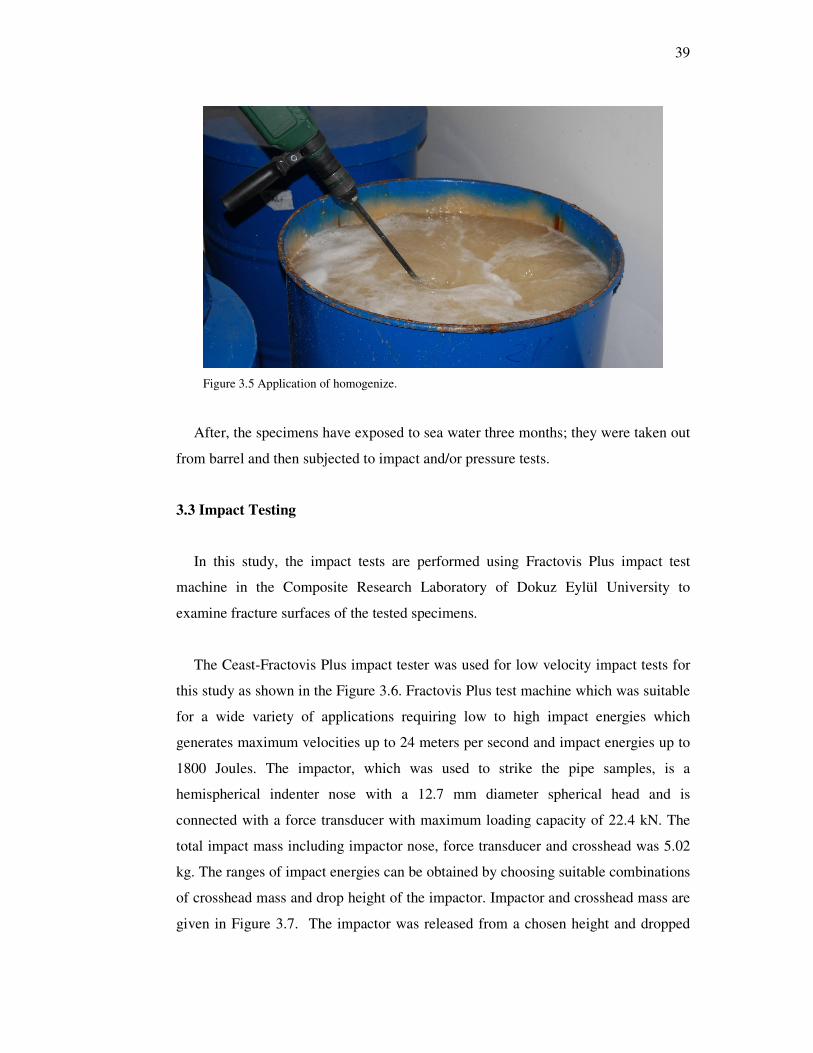
39
Figure 3.5 Application of homogenize.
After, the specimens have exposed to sea water three months; they were taken out
from barrel and then subjected to impact and/or pressure tests.
3.3 Impact Testing
In this study, the impact tests are performed using Fractovis Plus impact test
machine in the Composite Research Laboratory of Dokuz Eylül University to
examine fracture surfaces of the tested specimens.
The Ceast-Fractovis Plus impact tester was used for low velocity impact tests for
this study as shown in the Figure 3.6. Fractovis Plus test machine which was suitable
for a wide variety of applications requiring low to high impact energies which
generates maximum velocities up to 24 meters per second and impact energies up to
1800 Joules. The impactor, which was used to strike the pipe samples, is a
hemispherical indenter nose with a 12.7 mm diameter spherical head and is
connected with a force transducer with maximum loading capacity of 22.4 kN. The
total impact mass including impactor nose, force transducer and crosshead was 5.02
kg. The ranges of impact energies can be obtained by choosing suitable combinations
of crosshead mass and drop height of the impactor. Impactor and crosshead mass are
given in Figure 3.7. The impactor was released from a chosen height and dropped

40
freely along the guide columns. The contact force is measured with a load transducer
located on hemispherical nose. Instrumented impact test records contain the entire
impact event so that the full impact force versus time profile can be analyzed. The
Fractovis Plus impulse data acquisition system is the heart of impact testing system.
It captures load information at very high speed from impact tests then data is
analyzed graphically. The tester can get 16000 data per second from impact by
request. Data acquisition system records the electronic signals and converts them into
the impact parameters. The software used by the impact testing machine was capable
of calculating time dependent velocity, deflection and absorbed energy values from
load history given by the piezoelectric force transducer based on Newton’s second
law and kinematics with the assumption that the impactor is perfectly rigid.
The objective of impact testing is to determine an object's ability to resist high-
rate loading, which is measured by the energy absorbed to fracture a test piece at
high strain rate. Impact strength along with impact resistance is one of the most
commonly measured properties and to quantify of composite structures. The
impact resistance of a part is, in many applications, a critical measure of service
life. More importantly these days, it involves the perplexing problem of product
safety and liability (Naik, 2005).
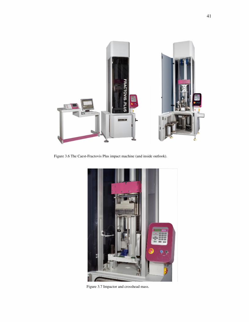
41
Figure 3.6 The Caest-Fractovis Plus impact machine (and inside outlook).
Figure 3.7 Impactor and crosshead mass.

42
The impact characteristics, such as peak load, contact duration; maximum
deflection and absorbed energy were examined against the corresponding impact
energies.
The force vs. time curve can be characterized by the peak force, the energy to
peak force, total energy, and displacement to maximum load. Maximum (peak)
load is the highest point in the load-time curve. Often the point of maximum load
corresponds to the onset of material damage or complete failure. Energy to
maximum load is the energy that the sample has absorbed up to the point of
maximum load. It is the area under the load/deflection curve from the test start to
the maximum load point. Total energy is the energy that the sample has absorbed
up to the end of the test, when the load reaches zero again. It is the area under the
load/deflection curve from the test start to the test end. Deflection to maximum
load is the distance the impactor traveled from the point of impact to the point of
maximum load (Naik, 2005).
Here the peak load is the maximum contact force between the impactor and the
composite tube at the contact point. Contact duration is determined as the total time
of contact between the impactor and the composite tubes. The maximum deflection
of a composite tube is defined as the largest depth on the top surface from the initial
position. The absorbed energy is the energy consumed between the impactor and the
specimen through the formation of damage and friction.
Impact load as a function of time f(t) and projectile tip displacement as a function
of time x(t) given by relation (3.1) and (3.2) respectively.
a(t)mf(t) o= (3.1)
( ) td a(t)dtvx(t) o∫ ∫+= (3.2)
where; a(t): Acceleration, mo: Projectile mass, vo: Projectile velocity just before
impact.
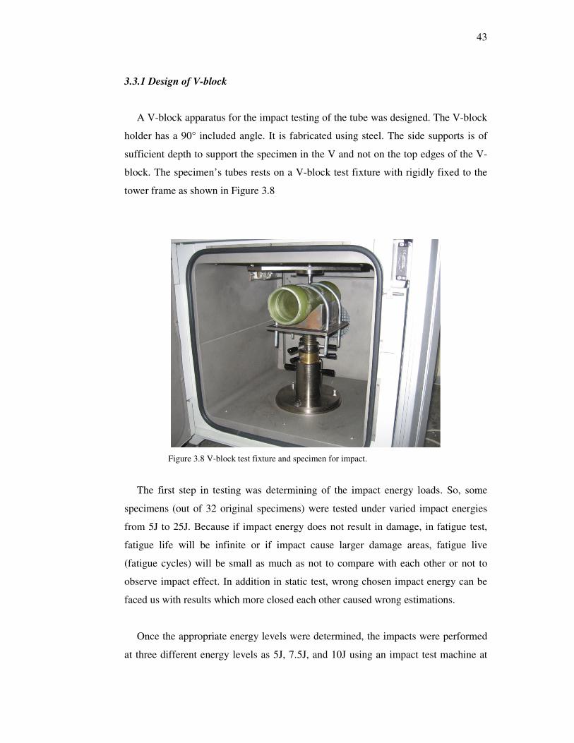
43
3.3.1 Design of V-block
A V-block apparatus for the impact testing of the tube was designed. The V-block
holder has a 90° included angle. It is fabricated using steel. The side supports is of
sufficient depth to support the specimen in the V and not on the top edges of the V-
block. The specimen’s tubes rests on a V-block test fixture with rigidly fixed to the
tower frame as shown in Figure 3.8
Figure 3.8 V-block test fixture and specimen for impact.
The first step in testing was determining of the impact energy loads. So, some
specimens (out of 32 original specimens) were tested under varied impact energies
from 5J to 25J. Because if impact energy does not result in damage, in fatigue test,
fatigue life will be infinite or if impact cause larger damage areas, fatigue live
(fatigue cycles) will be small as much as not to compare with each other or not to
observe impact effect. In addition in static test, wrong chosen impact energy can be
faced us with results which more closed each other caused wrong estimations.
Once the appropriate energy levels were determined, the impacts were performed
at three different energy levels as 5J, 7.5J, and 10J using an impact test machine at
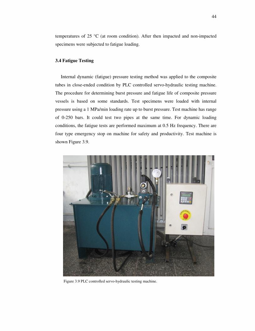
44
temperatures of 25 °C (at room condition). After then impacted and non-impacted
specimens were subjected to fatigue loading.
3.4 Fatigue Testing
Internal dynamic (fatigue) pressure testing method was applied to the composite
tubes in close-ended condition by PLC controlled servo-hydraulic testing machine.
The procedure for determining burst pressure and fatigue life of composite pressure
vessels is based on some standards. Test specimens were loaded with internal
pressure using a 1 MPa/min loading rate up to burst pressure. Test machine has range
of 0-250 bars. It could test two pipes at the same time. For dynamic loading
conditions, the fatigue tests are performed maximum at 0.5 Hz frequency. There are
four type emergency stop on machine for safety and productivity. Test machine is
shown Figure 3.9.
Figure 3.9 PLC controlled servo-hydraulic testing machine.

45
3.4.1 Experimental Setup
During all the internal pressure tests, following test apparatus was used to satisfy
the closed-end conditions of the composite tubes. The test apparatus and its
equipments are convenient to create the closed-end condition to ensure the
generalized plane strain case. Photographs of test apparatus and their set-up state in
Figure 3.10 and Figure 3.11, respectively. Sectional and general cutaway views of a
part of prepared specimen are given in Figure 3.12 and Figure 3.13 respectively.
Figure 3.10 A photograph of test apparatus.

46
Figure 3.11 A photograph of set up state of test apparatus.
Figure 3.12 Cutaway view of a part of prepared specimen for internal pressure
testing and subsections (Onder, 2009). A: Composite pressure vessel; B, D :
Compressing parts; C : Rubber seal element ;E : System locking member
component; F : Flange; G : Nut.

47
Figure 3.13 Cutaway view of prepared specimen for internal pressure testing (Onder,
2009).
A protective test box was manufactured for observing the test specimen during
pressure tests. It protects the harmful effects of the hydraulic oil during bursting of
the specimens as seen in Figure. It provides the observers’ protection from the test
specimen while taking photos and videos. Figure 3.14 shows a photo of the
protective test box.
Figure 3.14 A protective test box.
After impacted and unimpacted specimens were prepared, to first failure and burst
failure pressures of pipes were measured. In the dynamic loading, inner pressure was
performed from 30% to 70% of burst strength of the pipe. Burst pressures were
found from average values of the tests results, given information about correlation
between impact induced damages and burst pressures.

48
CHAPTER FOUR
RESULTS AND DISCUSSIONS
4.1 Impact testing
In this study, 24 tests were performed under impact energies as 5J, 7.5J, and 10J
in order to examine damage process in stacking sequences [±55°]3 at room
temperature. It is known that in composite tubes impacted with low energy,
degradation will be localized in the composite tube wall in the area closest to the
contact point. Inspection of fractured pieces was done after each test. First damage
created with 5J impact energies involves small delaminations, relatively. At higher
energies these delaminations propagate and are accompanied by the multiple
intralaminar delaminations. Images of impacted pipes are given in Figure 4.1. It is
clearly seen that delamination (damage area) is increased with increasing impact
energy.
The impact characteristics such as peak force, maximum deflection and total
absorbed energy are listed against the corresponding impact energies in Table 4.1,
4.2. These parameters are very important for FW-GFRP pipes subjected to impact
loading. Also, Impact test results of composite pipes for both dry and water
immersed conditions are given in Figure 4.2, 4.3 and 4.4.
It is clearly seen that peak force, maximum deflection and total absorbed energy
are increased with impact energy. The peak force values of water immersed
specimens seem to be greater than dry specimens. In addition max deflection and
total absorbed energy values have antipodal. This is likely due to that, pipes behave
plastically and becomes more flexible as exposed to sea water.

49
(a) (b) (c)
Figure 4.1 Illustration of impacted surface for three corresponding energy levels of the composite tubes (a) 5J, (b) 7.5J, and (c) 10J.

50
Table 4.1 Impact Properties of FW-GFRP composite pipes for dry condition
SPECIMENS
(Dry condition)
Peak Force
(N)
Maximum Deflection
(mm)
Total Absorbed
Energy (J)
5J1 1269.29 6.1384 4.13 5J2 1266.77 6.4306 4.34 5J3 1288.82 6.1466 4.18 5J4 1237.16 6.3603 4.28
5J average 1265.51 6.27 4.23 7.5J1 1561.57 7.5478 6.05 7.5J2 1457.00 8.5134 6.30 7.5J3 1512.44 7.5303 6.06 7.5J4 1532.28 8.0299 5.90
7.5J average 1515.82 7.91 6.08 10J1 1615.43 9.8139 9.32 10J2 1721.57 9.5734 8.37 10J3 1705.82 9.6577 8.57 10J4 1752.44 9.4606 8.37
10J average 1698.81 9.63 8.66
Table 4.2 Impact Properties of FW-GFRP composite pipes for sea water immersed condition
SPECIMENS
(Immersed
condition)
Peak Force
(N)
Maximum Deflection
(mm)
Total Absorbed
Energy (J)
5J1 1433.70 7.0504 2.92 5J2 1245.67 6.0767 3.58 5J3 1427.71 5.7552 3.03 5J4 1346.77 5.818 3.42
5J average 1363.46 6.18 3.24 7.5J1 1661.73 6.512 4.80 7.5J2 1663.93 6.4076 4.54 7.5J3 1571.02 7.012 4.50 7.5J4 1570.70 7.126 3.55
7.5J average 1616.85 6.76 4.35 10J1 1834.96 8.9675 6.99 10J2 1775.43 9.102 7.26 10J3 1782.67 9.002 7.67 10J4 1823.62 9.1486 6.91
10J average 1804.17 9.06 7.21

51
Figure 4.2 Peak force to impact energy graphs of the specimens in dry and immersed condition.
Figure 4.3 Maximum deflection to impact energy graphs of the specimens in dry and immersed
condition.

52
Figure 4.4 Total absorbed energy to impact energy graphs of the specimens in dry and immersed
condition.
The load–deflection curves give significant opinion about the impact response of
composite materials tested. Characteristic of load-deflection curves also includes
some useful tips in assessing damage process of composite tubes. Absorbed energy
in an impact event can be calculated from load-deflection curves.
Load-deflection curves, in general, can be classified as; closed type curve. As long
as a closed curve is observed it is possible to say that the impact loading does not
result in a serious damage to the specimen. The rebounding case results in closed
curves indicating the rebounding of the impactor from the specimen surface. The
load–deflection curve turned toward the origin of the diagram after reaching a
maximum force (rebounding).
In this study, typical load-deflection curves of the composite pipes subjected to
impact loading have one situation, rebounding. These curves are seen for 5J, 7.5J,
and 10J in Fig. 4.5 to 4.9. Peak force is increased with increasing performed impact
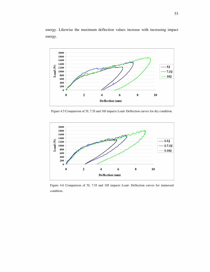
53
energy. Likewise the maximum deflection values increase with increasing impact
energy.
0
200
400
600
800
1000
1200
1400
1600
1800
2000
0 2 4 6 8 10
Deflection (mm)
Loa
d (
N)
5J
7.5J
10J
Figure 4.5 Comparison of 5J, 7.5J and 10J impacts Load- Deflection curves for dry condition.
0
200
400
600
800
1000
1200
1400
1600
1800
2000
0 2 4 6 8 10
Deflection (mm)
Loa
d (
N)
I-5J
I-7.5J
I-10J
Figure 4.6 Comparison of 5J, 7.5J and 10J impacts Load- Deflection curves for immersed
condition.

54
0
200
400
600
800
1000
1200
1400
1600
1800
2000
0 2 4 6 8 10
Deflection (mm)
Loa
d (
N)
5J
I-5J
Figure 4.7 Comparison of condition type of Load- Deflection curves for 5J impact.
0
200
400
600
800
1000
1200
1400
1600
1800
2000
0 2 4 6 8 10
Deflection (mm)
Loa
d (
N)
7.5J
I-7.5J
Figure 4.8 Comparison of condition type of Load- Deflection curves for 7.5J impact.
0
200
400
600
800
1000
1200
1400
1600
1800
2000
0 2 4 6 8 10
Deflection (mm)
Loa
d (
N)
10J
I-10J
Figure 4.9 Comparison of condition type of Load- Deflection curves for 10J impact.

55
Load-Time curves were generated for impact tests and it is given in Figure 4.10 to
4.14. As can be seen from these figures the maximum time values increase with
increasing impact energy. Also the average position of each curve gives us a hint
about the impact sensitivity of tubes.
It is seen in all graphs immersed specimens have little more contact duration and
peak force than dry specimens.
0
200
400
600
800
1000
1200
1400
1600
1800
2000
0 2 4 6 8 10 12 14 16
Time (ms)
Loa
d (
N)
5J
7.5J
10J
Figure 4.10 Comparison of 5J, 7.5J and 10J impacts Load- Time curves for dry condition.
0
200
400
600
800
1000
1200
1400
1600
1800
2000
0 2 4 6 8 10 12 14 16
Time (ms)
Loa
d (
N)
I-5J
I-7.5J
I-10J
Figure 4.11 Comparison of 5J, 7.5J and 10J impacts Load- Time curves for immersed
condition.

56
0
200
400
600
800
1000
1200
1400
1600
0 2 4 6 8 10 12 14 16
Time (ms)
Loa
d (
N)
5J
I-5J
Figure 4.12 Comparison of condition type of Load-Time curves for 5J impact.
0
200
400
600
800
1000
1200
1400
1600
1800
0 2 4 6 8 10 12 14 16
Time (ms)
Loa
d (
N)
7.5J
I-7.5J
Figure 4.13 Comparison of condition type of Load-Time curves for 7.5J impact.
0
200
400
600
800
1000
1200
1400
1600
1800
2000
0 5 10 15 20
Time (ms)
Loa
d (
N)
10J
I-10J
Figure 4.14 Comparison of condition type of Load-Time curves for 10J impact.
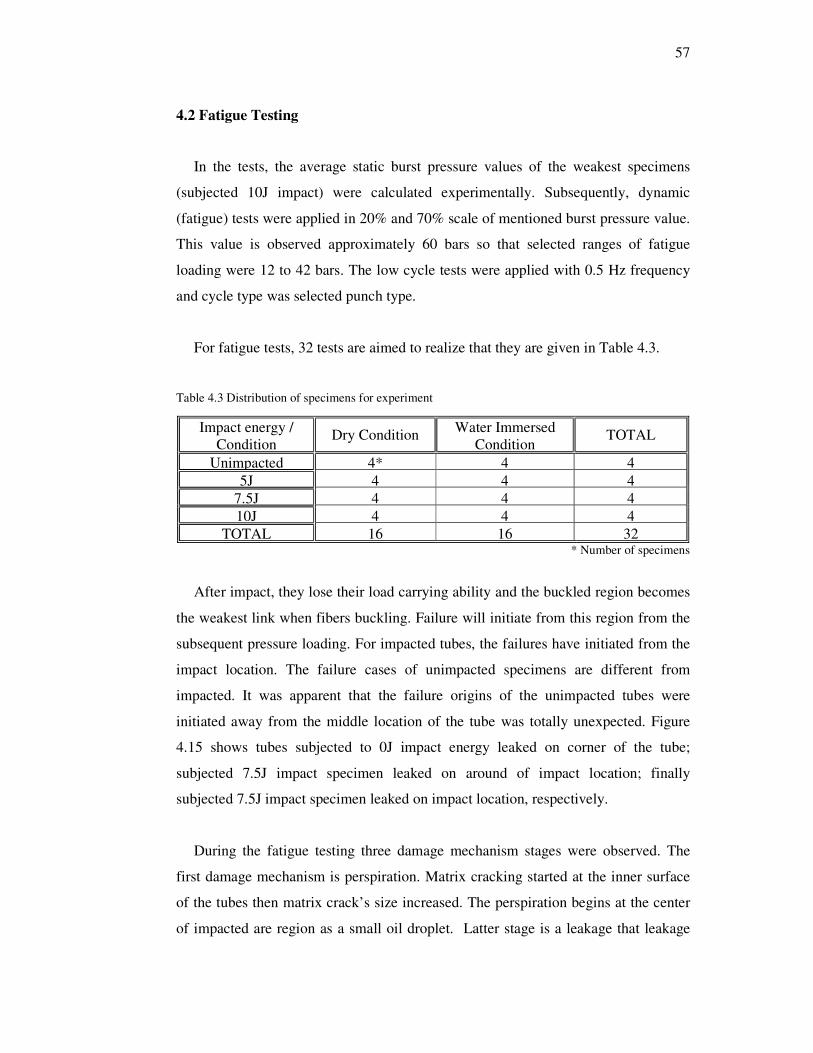
57
4.2 Fatigue Testing
In the tests, the average static burst pressure values of the weakest specimens
(subjected 10J impact) were calculated experimentally. Subsequently, dynamic
(fatigue) tests were applied in 20% and 70% scale of mentioned burst pressure value.
This value is observed approximately 60 bars so that selected ranges of fatigue
loading were 12 to 42 bars. The low cycle tests were applied with 0.5 Hz frequency
and cycle type was selected punch type.
For fatigue tests, 32 tests are aimed to realize that they are given in Table 4.3.
Table 4.3 Distribution of specimens for experiment
* Number of specimens
After impact, they lose their load carrying ability and the buckled region becomes
the weakest link when fibers buckling. Failure will initiate from this region from the
subsequent pressure loading. For impacted tubes, the failures have initiated from the
impact location. The failure cases of unimpacted specimens are different from
impacted. It was apparent that the failure origins of the unimpacted tubes were
initiated away from the middle location of the tube was totally unexpected. Figure
4.15 shows tubes subjected to 0J impact energy leaked on corner of the tube;
subjected 7.5J impact specimen leaked on around of impact location; finally
subjected 7.5J impact specimen leaked on impact location, respectively.
During the fatigue testing three damage mechanism stages were observed. The
first damage mechanism is perspiration. Matrix cracking started at the inner surface
of the tubes then matrix crack’s size increased. The perspiration begins at the center
of impacted are region as a small oil droplet. Latter stage is a leakage that leakage
Impact energy / Condition
Dry Condition Water Immersed Condition
TOTAL
Unimpacted 4* 4 4 5J 4 4 4
7.5J 4 4 4 10J 4 4 4
TOTAL 16 16 32

58
initiates when the matrix cracks coalescence reached the point in which the
pressurized oil can penetrate through these cracks to reach the surface of the tube as
surface wetting. Due to cracks coalescence from inner surface towards outer surface,
a leakage path is formed. After a few cycles, the tubes reach the point where small
matrix cracks turn into bigger cracks that allow an intense oil leakage. At each cycle,
the oil penetrates through the matrix cracks and helps to open them, and the cracks
coalesce quickly and turn the slight leakage into intense leakage. So, it is observed
that these cracks have opened and closed at each cycles by means of internal
pressure. Leakage increased gradually with continuing of cycling. After then with
damage propagation, on the specimens, jet case is occurred. The composite tubes
were loaded internal pressure until failure. Therefore, in tests after a few numbers of
cycles (about 2000-3000) the test is finished. Phases of fatigue life of specimen are
demonstrated in Figure 4.16 to 4.24. Perspiration phases are not demonstrated on
figures due to needing camera with too much high solution to observe oil droplet.

59
(a) (b) (c)
Figure 4.15 Illustration of fatigued specimens for three corresponding type of the leakages (a) 10J, (b) 7.5J and (c) 7.5J

60
Figure 4.16 Leakage state of fatigue loading of composite pipe.
Figure 4.17 Advanced leakage state of fatigue loading of composite pipe.
Leakage point (impact point)

61
Figure 4.18 Strong leakage state of fatigue loading of composite pipe.
Figure 4.19 Jet I state of fatigue loading of composite pipe.

62
Figure 4.20 Jet II state of fatigue loading of composite pipe.
Figure 4.21 Jet III state of fatigue loading of composite pipe.

63
Figure 4.22 Jet IV state of fatigue loading of composite pipe.
Figure 4.23 Exact jet state of fatigue loading of composite pipe.

64
Figure 4.24 Eruption state of fatigue loading of composite pipe.
In order to determine the fatigue life, “the perspiration state” is selected for
utilization of the performance limit of the pipes.
In Table 4.4, perspiration and leakage failure cycles of water immersed and dry
condition specimens are given.

65
Table 4.4 Average cycle number for corresponding impact energy on dynamic test of composite tubes
Specimens For Dynamic
Loading
Dry condition 3rd month immersed
Perspiration Failure Cycles
Leakage Failure Cycles
Perspiration Failure Cycles
Leakage Failure Cycles
0J-1 47300 81447 60000 - 0J-2 17369 24200 - - 0J-3 - - - - 0J-4 51111 - 41000 60000
0J- Average 38593 52824 50500 60000 5J-1 36 1800 16250 27500 5J-2 2952 3600 19750 32500 5J-3 2354 8000 - - 5J-4 10287 17147 - -
5J- Average 3907 7637 18000 30000 7.5J-1 - 4532 - 29145 7.5J-2 30 1200 20000 21727 7.5J-3 30 - 11639 14014 7.5J-4 1805 2100 6373 -
7.5J- Average 622 2611 12671 21629 10J-1 - 73 - 8500 10J-2 - 29 - 800 10J-3 - 575 3500 15089 10J-4 - 610 - -
10J- Average 161 322 3500 8130
Average fatigue cycle to impact energy curve graphs are given below in Figure
4.33. Figure 4.34 are derived from above Table 4.4.
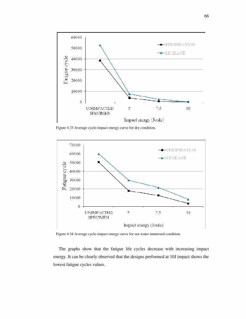
66
Figure 4.33 Average cycle-impact energy curve for dry condition.
Figure 4.34 Average cycle-impact energy curve for sea water immersed condition.
The graphs show that the fatigue life cycles decrease with increasing impact
energy. It can be clearly observed that the designs performed at 10J impact shows the
lowest fatigue cycles values.

67
4.2.1 Fatigue Observations
In general, about tests specimens within dry condition can be comment like
below.
In total 16 experiments, result of completion dynamic loading, one of the
specimens (0J-3) had no damage (perspiration, leakage or eruption). Four of the
specimens are shown regression and unstable leakage. Also It is seen that leakage on
8 specimens and jet on 6 specimens.
For unimpacted specimens, the owing to too much cycles than impacted
specimens some tests have being continued 30-40 hours. In general, the perspiration
is considered as first failure point. Since the damage propagation required too much
cycles, advanced leakage and jet phases are not seen.
On second and third specimens of subjected to 5J impact energy, regressions are
seen. With the experiment that has too much cycle and more specimens, estimations
will be closer to the absolute truth. Consequently, in some specimens progressive
fatigue mechanic has not been seen as estimated.
Results’ dynamic loading of 7.5J and 10J impacted specimens have carried out as
estimated so leakage and jet developed with gradually are understood for trend of
cycle numbers.
In general, about tests specimens within sea water immersed condition can be
comment like this. In total 16 experiments, result of completion dynamic loading,
five of the specimens (0J-2, 0J-3, 5J-3, 5J-4 and 10J-4) have not carried out because
of they had no damage (perspiration, leakage or eruption). Other tests of water
immersed condition have displayed same trend like dry condition. One disparity
most of failure phase have higher cycle than dry condition specimens.

68
CHAPTER FIVE
CONCLUSIONS AND RECOMMENDATIONS
5.1 Conclusions
This section presents the conclusions obtained from the analysis of the
experimental data of low velocity impact and fatigue tests conducted on the filament
wound-glass fiber reinforced plastic (FW-GFRP) pipes. Also the sea water effect on
the fatigue life is studied. The following results are noticed from study;
5.1.1 Results of the Impact Tests
• Firstly, the transverse impact behaviors of the FW-GFRP pipes are examined.
• The impact characteristics, such as peak load, contact duration, maximum
deflection vs. impact energies are plotted.
• Load-deflection curves of all impact tests have one case, rebounding. So none of
specimens are perforated.
• First damage created under 5J, caused small delaminations including matrix and
fiber cracking. At higher energies these delaminations propagate and are
accompanied by the delaminations.
• It is clearly seen that contact time, peak force, maximum deflection and total
absorbed energy are increased due to increasing impact energy both of the type
of specimen, for all that the peak force values of water immersed specimens
have trended greater than dry specimens in addition max deflection and total
absorbed energy values have antipodal. Because of mentioned state is estimated
as sea water immersion has become more plasticize to pipes so that pipes are
behaved more flexible.
5.1.2 Results of the Fatigue Tests
• For unimpacted tubes, the failures that initiated away from the middle location of
the tube were totally unexpected. On the other hand, naturally, the failure of the
impacted tubes was initiated from the impact area.
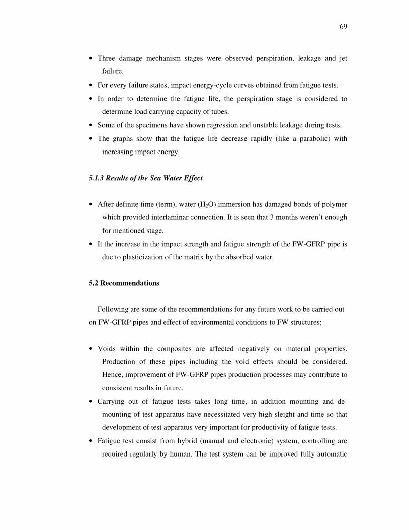
69
• Three damage mechanism stages were observed perspiration, leakage and jet
failure.
• For every failure states, impact energy-cycle curves obtained from fatigue tests.
• In order to determine the fatigue life, the perspiration stage is considered to
determine load carrying capacity of tubes.
• Some of the specimens have shown regression and unstable leakage during tests.
• The graphs show that the fatigue life decrease rapidly (like a parabolic) with
increasing impact energy.
5.1.3 Results of the Sea Water Effect
• After definite time (term), water (H2O) immersion has damaged bonds of polymer
which provided interlaminar connection. It is seen that 3 months weren’t enough
for mentioned stage.
• It the increase in the impact strength and fatigue strength of the FW-GFRP pipe is
due to plasticization of the matrix by the absorbed water.
5.2 Recommendations
Following are some of the recommendations for any future work to be carried out
on FW-GFRP pipes and effect of environmental conditions to FW structures;
• Voids within the composites are affected negatively on material properties.
Production of these pipes including the void effects should be considered.
Hence, improvement of FW-GFRP pipes production processes may contribute to
consistent results in future.
• Carrying out of fatigue tests takes long time, in addition mounting and de-
mounting of test apparatus have necessitated very high sleight and time so that
development of test apparatus very important for productivity of fatigue tests.
• Fatigue test consist from hybrid (manual and electronic) system, controlling are
required regularly by human. The test system can be improved fully automatic

70
• computer-controlled and joined acoustic emission system for sensitive observing.
• Microscopic analysis of the impact damaged specimens can be carried out to have
an in-depth failure analysis.
• Test specimens must are exposed the sea water immersion 6, 9 and 12 months too,
for seeing further damage mechanism of it.

71
REFERENCES
Abrate, S. (1998). Impact on composite structures. Cambridge: Cambridge
University Press.
Akil, H. M., Cheng, L. W., Mohd Ishak, Z. A., Abu Bakar, A., & Abd Rahman, M.
A. (2009). Water absorption study on pultruded jute fiber reinforced unsaturated
polyester composites. Composites Science and Technology, 69, 1942–1948.
Arikan, H. (2010). Failure analysis of [±55°] filament wound composite pipes with
an inclined surface crack under static internal pressure. Compos ite Structures, 92,
182–187.
Atas, C. (2004). Large deformations in composite laminated plates. Doctor of
Philosophy thesis. Izmir: Faculty of School Natural and Applied Sciences of
Dokuz Eylul University.
Avci, A., Sahin, O. S., & Tarakcioglu, N. (2007). Fatigue behavior of surface
cracked filament wound pipes with high tangential strength in corrosive
environment. Composites, Part A, 38, 1192–1199.
Bie, H., Li, X., Liu, P., Liu Y., & Xu, P. (2009). Fatigue life evaluation of high
pressure hydrogen storage vessel. International Journal of Hydrogen Energy, in
press.
Chang, D. J. (2003). Burst tests of filament-wound graphite-epoxy pipes. Journal of
Composite Materials, 37, 811-829.
Chang, R. R. (2000). Experimental and theoretical analyses of first-ply failure of
laminated composite pressure vessels. Composite Structures, 49, 237-243.

72
Changliang Z., Mingfa R., Wei Z., & Haoran C. (2006). Delamination prediction of
composite filament wound vessel with metal liner under low velocity impact.
Composite Structures, in press.
Chib, A. (2003). Parametric study of low velocity impact analysis on composite
tubes. Master of Science thesis. Maharashtra: Faculty of School Natural and
Applied Sciences of Wichita State University.
Curtis, J., Hinton, M. J., Li, S., Reid, S. R., & Soden, P. D. (2000). Damage,
deformation and residual burst strength of filament-wound composite pipes
subjected to impact or quasi-static indentation. Composites, Part B, 31, 419-433.
Davies, P., Mazeas, F., & Casari, P. (2001). Sea water aging of glass reinforced
composites: shear behavior and damage modelling. Journal of Composite
Materials, 35, 1343–30.
Davies, P., Riou, L., Mazeas, F., & Warnier, P. (2005). Thermoplastic composite
cylinders for underwater applications. Journal of Thermoplastic Composite
Materials, 18 (5), 417-443.
Dhakal, H. N., Zhang, Z. Y., & Richardson, M. O. W. (2007). Effect of water
absorption on the mechanical properties of hemp fiber reinforced unsaturated
polyester composites. Composites Science and Technology, 67, 1674–1683.
Dogan, T. (2006). Prediction of composite vessels under various loadings. Master of
Science thesis. Izmir: Faculty of School Natural and Applied Sciences of Dokuz
Eylul University.
Doyum, A. B., & Altay, U. B. (1997). Low-velocity impact damage in glass
fiber/epoxy cylindrical tubes. Materials & Design, 18 (3), 131–135.
73
Erkal, S. (2007). Fatigue damage on composite cylinders. Master of Science thesis.
Izmir: Faculty of School Natural and Applied Sciences of Dokuz Eylul
University.
Farias, M. A., Farina, M. Z., Pezzin, A. P. T., & Silva, D. A. K. (2009). Unsaturated
polyester composites reinforced with fiber and powder of peach palm: Mechanical
characterization and water absorption profile. Materials Science and Engineering,
C 29, 510–513.
Filament winding, (n.d.). Retrieved May 1, 2010, from
http://en.wikipedia.org/wiki/Filament_winding
Filament wound materials, (n.d.). Retrieved May 1, 2010, from
http://www.ckcomposites.com/technical-data.php
Gellert, E. P., & Turley, D. M. (1999). Sea water immersion ageing of glass-fiber
reinforced polymer laminates for marine applications. Composites, Part A, 30,
1259–1265.
Gemi, L., Tarakcioglu, N., Akdemir, A., & Sahin, O. S. (2009). Progressive fatigue
failure behavior of glass/epoxy [±75°]2 filament-wound pipes under pure internal
pressure. Materials and Design, 30, 4293–4298.
Gning, P. B., Tarfaoui, M., Collombet, F., & Davies, P. (2005). Prediction of
damage in composite cylinders after impact. Journal of Composite Materials, 39
(10), 917–928.
Gning, P. B., Tarfaoui, M., Collombet, F., Riou, L., & Davies, P. (2005). Damage
development in thick composite pipes under internal loading and influence on
implosion pressure: experimental observations. Composites, Part B, 36, 306-318.
74
Gu, H., & Hongxia, S. (2007). Effect of water absorption on the mechanical
properties of glass/polyester composites. Materials and Design, 28, 1647–1650.
Gu, H., & Hongxia, S. (2008). Delamination behavior of glass/polyester composites
after water absorption. Materials and Design, 29, 262–264.
Jones R. M. (1999). Mechanics of composite materials. (2nd ed.). Philadelphia:
Taylor & Francis Group LLC.
Kaneko, T., Ujihashi, S., Yomoda, H., & Đnagi, S. (2008). Finite element method
failure analysis of a pressurized FRP cylinder under transverse impact loading.
Thin Walled Structures, 46, 898–904.
Karbhari, V. M., Haller, J. E., Falzon, P. K., & Hersberg, I. (1999). Post-impact
crush of hybrid braided composite tubes. International Journal of Impact
Engineering, 22, 419-433.
Kelkar, A. D., Jitendra, S., Bolick, T., & Bolick, R. (2003). Introduction to low cost
manufacturing of composite laminates. Proceedings of the 2003 American Society
for Engineering Education Annual conference & Exposition, Session 2003-1482.
Khalid, Y. A., Hamed, A. F., & Sapuan, S. M. (2007). Pressure carrying capacity of
reinforced plastic tubes. Polymer-Plastics Technology and Engineering, 46, 651–
659.
Kim, U. C., Kang, J. H., Hong C. S., & Kim C. G. (2005). Optimal design of
filament wound structures under internal pressure based on the semi-geodesic path
algorithm. Composite Structures, 67, 443–452.
Kobayashi, S., Đmai, T., & Wakayama, S. (2007). Burst strength evaluation of the
FW-CFRP hybrid composite pipes considering plastic deformation of the liner.
Composites, Part A, 38, 1344–1353.

75
Kootsookos, A., & Mouritz, A. P. (2004). Sea water durability of glass- and carbon-
polymer composites. Composites Science and Technology, 64, 1503–1511.
Liao, K., Schulthelsz, C. R., & Hunston D. L. (1999). Effects of environmental aging
on the properties of pultruded GFRP. Composites, Part B, 30, 485–493.
Mallick, P.K. (2007). Fiber-reinforced composites : materials, manufacturing, and
design. (3rd ed.). Boca Raton: Taylor & Francis Group, LLC.
Mazumdar, S. K. (2002). Composites manufacturing : materials, product, and
process engineering. Boca Raton: CRC Press LLC.
Naik, M. K. (2005). The effect of environmental conditions on the hydrostatic burst
pressure and impact performance of glass fiber reinforced thermoset pipes.
Master of Sicience thesis, Dhahran: Faculty of School Natural and Applied
Sciences of Kinh Fahd University of Petroleum & Minerals.
Onder, A. (2007). First failure pressure of composite pressure vessels. Master of
Science thesis. Izmir: Faculty of School Natural and Applied Sciences of Dokuz
Eylul University.
Onder, A., Sayman, O., Dogan, T., & Tarakcioglu, N. (2009). Burst failure load of
composite pressure vessels. Composite Structures, 89, 159–166.
Sahin, O. S., Akdemir, A., Avci, A., & Gemi, L. (2008). Fatigue crack growth
behavior of filament wound composite pipes in corrosive environment. Journal of
Reinforced Plastics and Composites, in press.
Samanci, A., Avci, A., Tarakcioglu, N., & Sahin, O. S. (2008). Fatigue crack growth
of filament wound GRP pipes with a surface crack under cyclic internal pressure.
Journal of Material Science, 48, 5569–5573.

76
Shyr, T. W., Pan, Y. H. (2003). Impact resistance and damage characteristics of
composite laminates. Composite Structures, 62, 193-203.
Silva, R. V. (2008). Curaua/glass hybrid composite: the effect of water aging on the
mechanical properties. Journal of Reinforced Plastics and Composites, in press.
Sun, X. K., Du, S. Y., & Wang, G. D. (1999). Bursting problem of filament wound
composite pressure vessels. International Journal of Pressure Vessels and Piping,
76, 55–59.
Tarakcioglu, N., Akdemir, A., & Avci, A. (2001). Strength of filament wound GRP
pipes with surface crack. Composites, Part B, 32, 131-138.
Tarakcioglu, N., Gemi, L., & Yapici, A. (2005). Fatigue failure behavior of
glass/epoxy ±55 filament wound pipes under internal pressure. Composites
Science and Technology, 65 703–708.
Tarakcioglu, N., Samanci, A., Arikan, H., & Akdemir, A. (2007). The fatigue
behavior of [±55°]3 filament wound GRP pipes with a surface crack under internal
pressure. Composite Structures, 8 (2), 207–211.
Tarfaoui, M., Gning, P. B., & Collombet, F. (2007). Residual strength of damaged
glass/epoxy tubular structures. Journal of Composite Materials, 41, 2165-2183.
Tarfaoui, M., Gning, P. B., Davies, P., & Collombet, F. (2007). Scale and size effects
on dynamic response and damage of glass/epoxy tubular structures. Journal of
Composite Materials, 41, 547-559.
Tarfaoui, M., Gning, P. B., & Hamitouche L. (2008). Dynamic response and damage
modeling of glass epoxy tubular structures: Numerical investigation. Composites,
Part A 39, 1–12.

77
Xu, P., Zheng, J. Y., & Liu, P. F. (2009). Finite element analysis of burst pressure of
composite hydrogen storage vessels. Materials and Design, 30, 2295–2301.
Velosa, J. C., Nunes, J. P., Antunes, P. J., Silva, J. F., & Marques, A. T. (2009).
Development of a new generation of filament wound composite pressure
cylinders. Composites Science and Technology, 69, 1348–1353.
Wakayama, S., Kobayashi, S., Đmai, T., & Matsumoto, T. (2002). Evaluation of burst
strength of FW-FRP composite pipes after impact using pitchbased low-modulus
carbon fiber. Composites, Part A, 37, 2002-2010.
Yaylagan, E. (2010). Failure pressure of composite cylinders with a plastic liner.
Master of Science thesis. Izmir: Faculty of School Natural and Applied Sciences
of Dokuz Eylul University.
Zheng, J. Y., & Liu P. F. (2008). Elasto-plastic stress analysis and burst strength
evaluationof Al-carbon fiber/epoxy composite cylindrical laminates.
Computational Materials Science, 42, 453–461.
Zou, Z., Reid, S. R., Li, S., & Soden P. D. (2002). Application of a delamination
model to laminated composite structures. Composite Structures, 56, 375–389.


