45
MAE 6530 - Propulsion Systems II Section 4.1: Introduction to Jet Propulsion

MAE 6530 - Propulsion Systems II
Section 4.1: Introduction to Jet Propulsion

MAE 6530 - Propulsion Systems II
Jet Propulsion Basics
Suck
Squeeze Bang
Blow
2
Credit:USAFTestPilotSchool
MAE 6530 - Propulsion Systems II
MAE 6530 - Propulsion Systems II
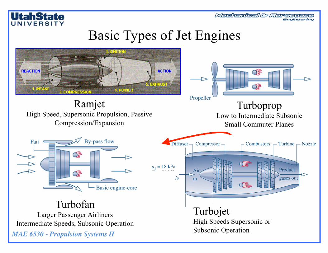
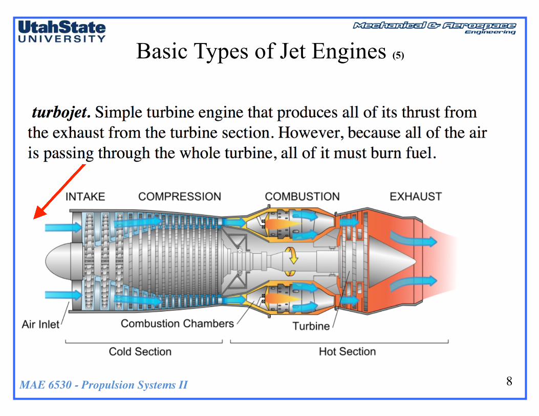
Basic Types of Jet Engines
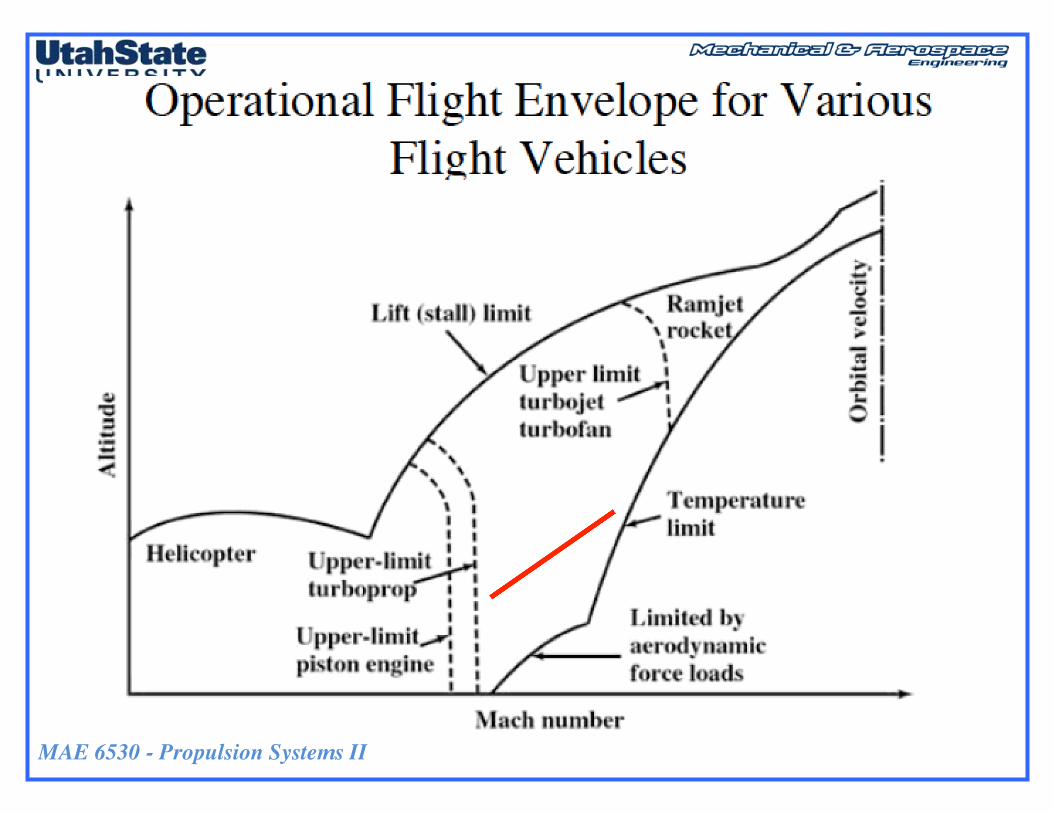
TurbopropLow to Intermediate Subsonic
Small Commuter Planes
RamjetHigh Speed, Supersonic Propulsion, Passive
Compression/Expansion
TurbojetHigh Speeds Supersonic or Subsonic Operation
TurbofanLarger Passenger Airliners
Intermediate Speeds, Subsonic Operation
MAE 6530 - Propulsion Systems II
Basic Types of Jet Engines (2)
5
• Thrust produced by increasing the kinetic energy of the air in the opposite direction of flight
• Slight acceleration of a large mass of airà Engine driving a propeller
• Large acceleration of a small mass of airàTurbojet or turbofan engine
• Combination of bothà Turboprop engine
MAE 6530 - Propulsion Systems II
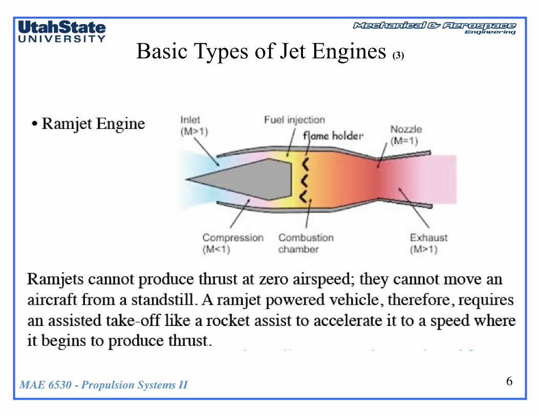
Basic Types of Jet Engines (3)
6

MAE 6530 - Propulsion Systems II
Basic Types of Jet Engines (4)
• Turbojet/Turbo fan engines CombustionCycle steps
• Compression and Power extractionsteps useTurbo-machineryTo augment cycle
• Ramjet Achieves CompressionAcross Inlet shockwaves
CompressorCombustor
Turbine
Nozzle
Afterburner
Compressor
Combustor
Turbine
Afterburner
NozzleFan
Turbojet
Turbofan
Inlet
Inlet
7
MAE 6530 - Propulsion Systems II
Basic Types of Jet Engines (5)
8

MAE 6530 - Propulsion Systems II
Basic Types of Jet Engines (6)
9

MAE 6530 - Propulsion Systems II
Brayton Cycle for Jet PropulsionStep Process1) Intake (suck) Isentropic Compression2) Compress the Air (squeeze) Adiabatic Compression3) Add heat (bang) Constant Pressure Combustion4) Extract work (blow) Isentropic Expansion in Nozzle5) Exhaust Heat extraction by surroundings
(CreditNarayananKomerath,GeorgiaTech)
…step5abovehappensIntheexhaustplumeandhasminimalEffectonengineperformance
Step1-2
Step3
Step4
Step5
10
-5
Step6
MAE 6530 - Propulsion Systems II
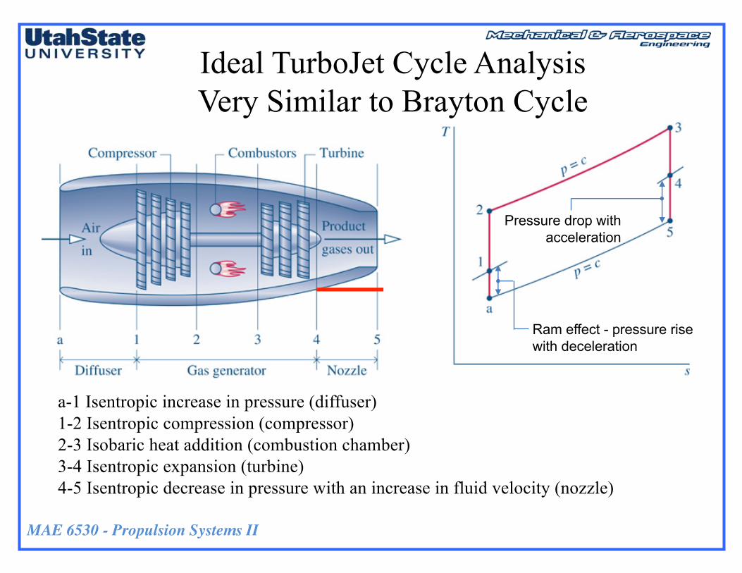
Ideal TurboJet Cycle Analysis Very Similar to Brayton Cycle
Ram effect - pressure rise with deceleration
Pressure drop with acceleration
a-1 Isentropic increase in pressure (diffuser)1-2 Isentropic compression (compressor)2-3 Isobaric heat addition (combustion chamber)3-4 Isentropic expansion (turbine)4-5 Isentropic decrease in pressure with an increase in fluid velocity (nozzle)

MAE 6530 - Propulsion Systems II
Idealized Thermodynamic ModelConservation of Energy -àEnthalpy Out = Enthalpy In + Heat Added-work performed
• Isentropic FlowThru Diffuser, Nozzle
• No Heat, Friction Loss in Compressor,Turbine
MAE 6530 - Propulsion Systems II
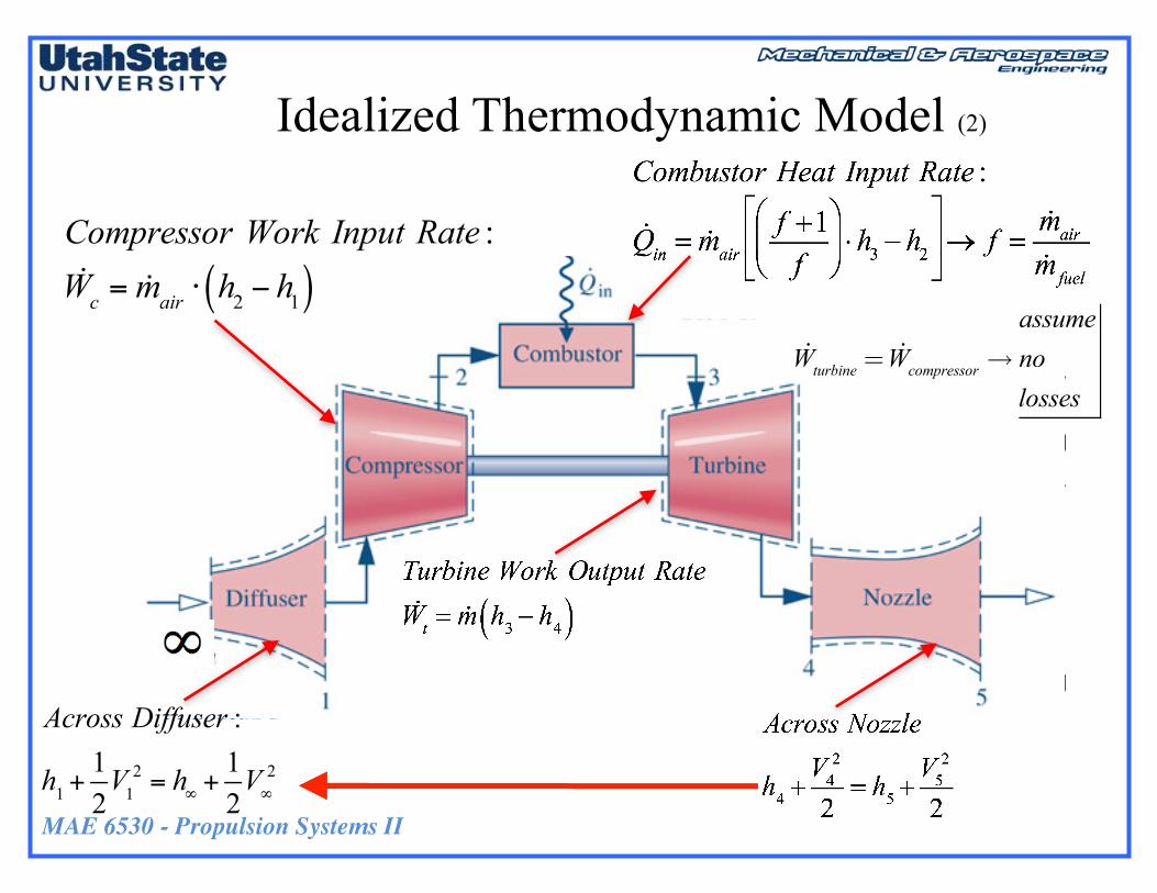
Idealized Thermodynamic Model (2)
Across Diffuser :
h1+12V1
2 = h∞ +12V∞
2
Compressor Work Input Rate :!Wc = !mair ⋅ h2 − h1( )
!Wturbine = !Wcompressor→assumenolosses

MAE 6530 - Propulsion Systems II
Idealized Thermodynamic Model (3)
• Energy balance à change in the stagnation enthalpy rate of the gas flow between the exit and entrance of the engine is equal to the added chemical enthalpy rate of the injected fuel flow.
• Letting
exit (5)
in (∞)

MAE 6530 - Propulsion Systems II
Idealized Thermodynamic Model (3)
• The high energy content of hydrocarbon fuels is remarkably large and allow extended powered flight to be possible.
Credit:B.CantwellStanford
MAE 6530 - Propulsion Systems II
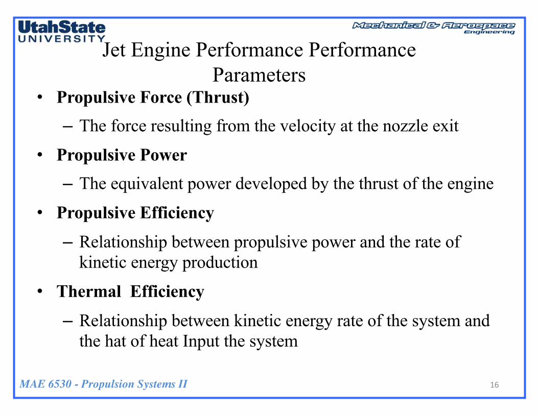
Jet Engine Performance Performance Parameters
• Propulsive Force (Thrust)
– The force resulting from the velocity at the nozzle exit
• Propulsive Power
– The equivalent power developed by the thrust of the engine
• Propulsive Efficiency
– Relationship between propulsive power and the rate of kinetic energy production
• Thermal Efficiency
– Relationship between kinetic energy rate of the system and the hat of heat Input the system
16

MAE 6530 - Propulsion Systems II
Propulsive and Thermal Efficiency of Cycle
17
Thermal Efficiency =
Propulsive Efficiency =
Kinetic energy production rate
Propulsive power
Kinetic energy production rate
Combustion Enthalpy of
Fuel
Look a Product of Efficiencies

MAE 6530 - Propulsion Systems II
Jet Engine Performance – Propulsive and Thermal Efficiency
18
Overall Thermodynamic Cycle Efficiency =
Net Propulsion Power Output/Net Heat Input
Look a Product of Efficiencies
ηoverall =ηthermalηpropulsive

MAE 6530 - Propulsion Systems II
Jet Engine Performance Efficiencies
19
Propulsive PowerThe power developed from the
thrust of the engine
exit (5)
Propulsive Efficiency Ratio of Power Developed from Engine (desired beneficial output) Thrust to Change in Kinetic Energy of the Moving Airstream (cost of propulsion) Thrust Equation:
in (∞)
MAE 6530 - Propulsion Systems II
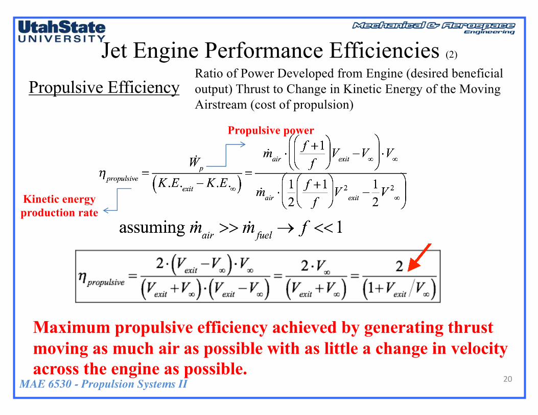
Jet Engine Performance Efficiencies (2)
20
Kinetic energy production rate
Propulsive power
Propulsive EfficiencyRatio of Power Developed from Engine (desired beneficial output) Thrust to Change in Kinetic Energy of the Moving Airstream (cost of propulsion)
Maximum propulsive efficiency achieved by generating thrust moving as much air as possible with as little a change in velocity across the engine as possible.
MAE 6530 - Propulsion Systems II
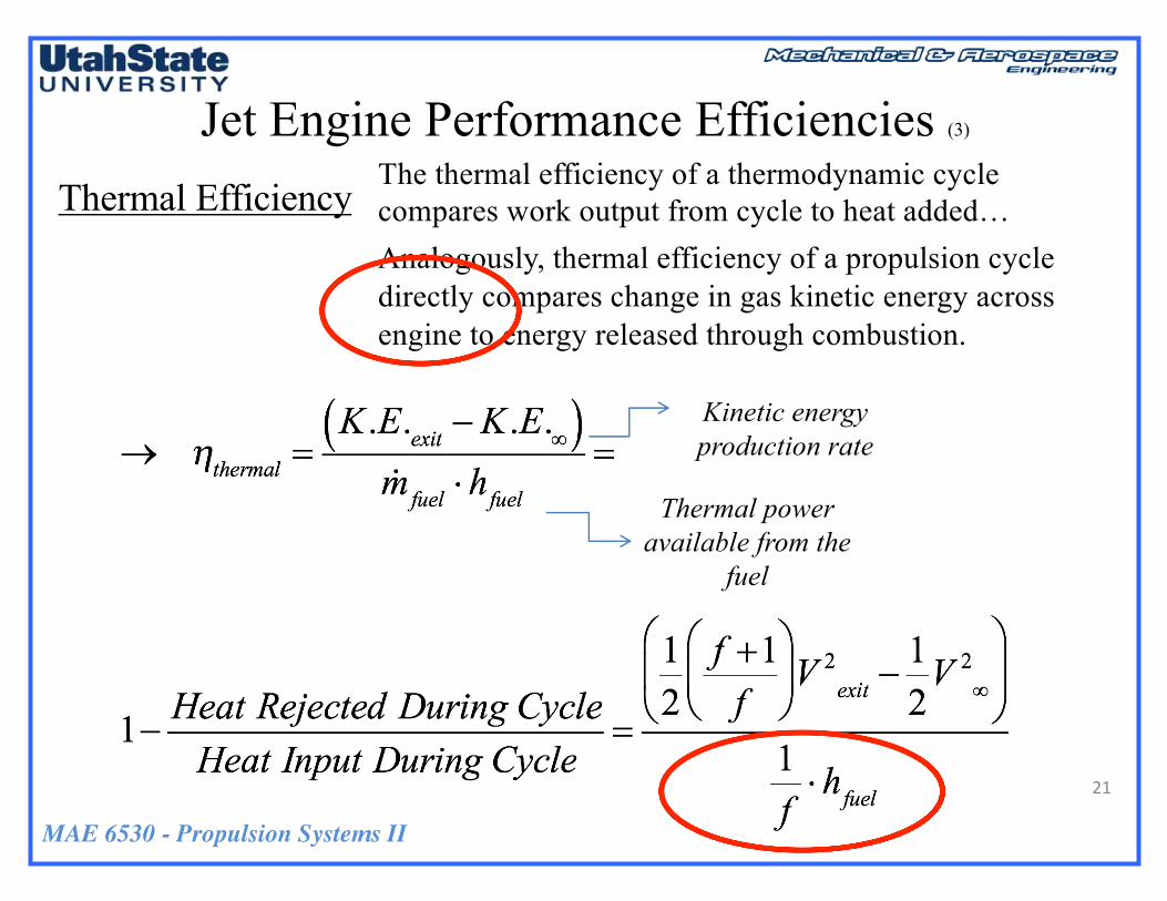
Jet Engine Performance Efficiencies (3)
21
Thermal Efficiency
Kinetic energy production rate
Thermal power available from the
fuel
The thermal efficiency of a thermodynamic cycle compares work output from cycle to heat added…Analogously, thermal efficiency of a propulsion cycle directly compares change in gas kinetic energy across engine to energy released through combustion.

MAE 6530 - Propulsion Systems II
Jet Engine Performance Efficiencies (4)
22
• Rewriting the expression
• Rewriting in terms of the gas enthalpies where
MAE 6530 - Propulsion Systems II
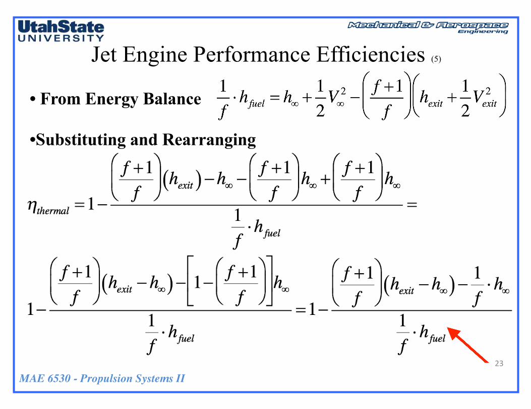
Jet Engine Performance Efficiencies (5)
23
• From Energy Balance
•Substituting and Rearranging
MAE 6530 - Propulsion Systems II
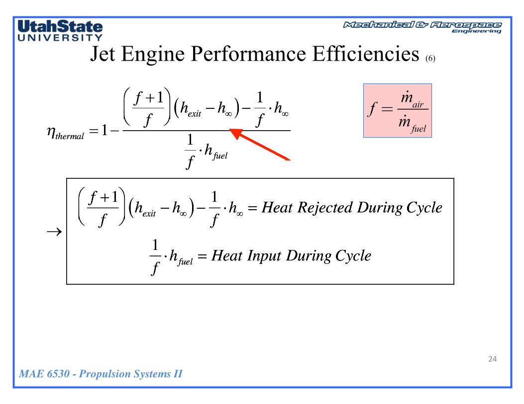
Jet Engine Performance Efficiencies (6)
24
f =!mair!mfuel
MAE 6530 - Propulsion Systems II
Jet Engine Performance Efficiencies (7)
25
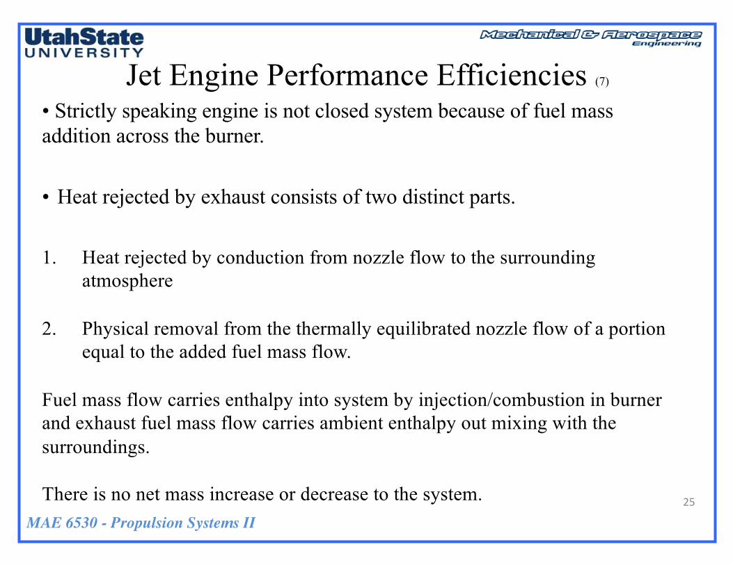
• Strictly speaking engine is not closed system because of fuel mass addition across the burner.
• Heat rejected by exhaust consists of two distinct parts.
1. Heat rejected by conduction from nozzle flow to the surrounding atmosphere
2. Physical removal from the thermally equilibrated nozzle flow of a portion equal to the added fuel mass flow.
Fuel mass flow carries enthalpy into system by injection/combustion in burner and exhaust fuel mass flow carries ambient enthalpy out mixing with the surroundings.
There is no net mass increase or decrease to the system.

MAE 6530 - Propulsion Systems II
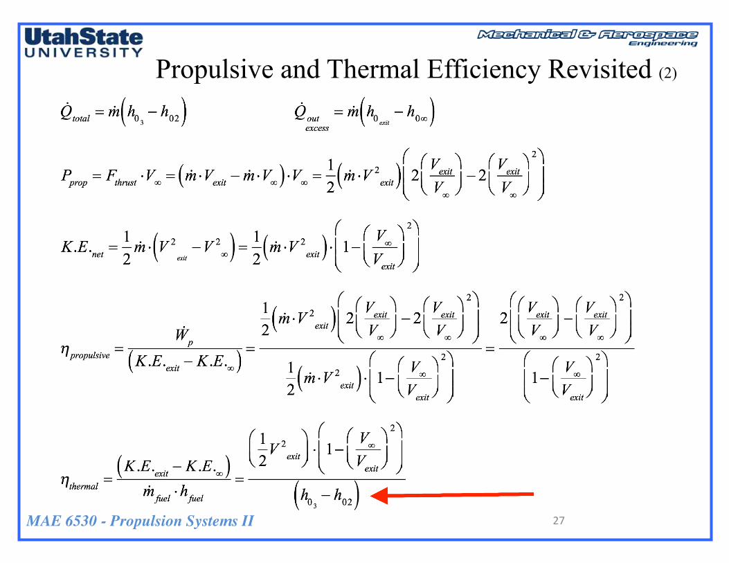
Propulsive and Thermal Efficiency Revisited
@ Cruise Assumed Optimized Nozzle à pexit = p∞
NozzleEnthalpyBalance
!m h4 +V42
2⎛
⎝⎜⎞
⎠⎟= !m h5 +
V52
2⎛
⎝⎜⎞
⎠⎟= !m hexit +
Vexit2
2⎛
⎝⎜⎞
⎠⎟→V4 ≈ 0→Vexit = 2 h4 − hexit( )
MAE 6530 - Propulsion Systems II
Propulsive and Thermal Efficiency Revisited (2)
27
MAE 6530 - Propulsion Systems II
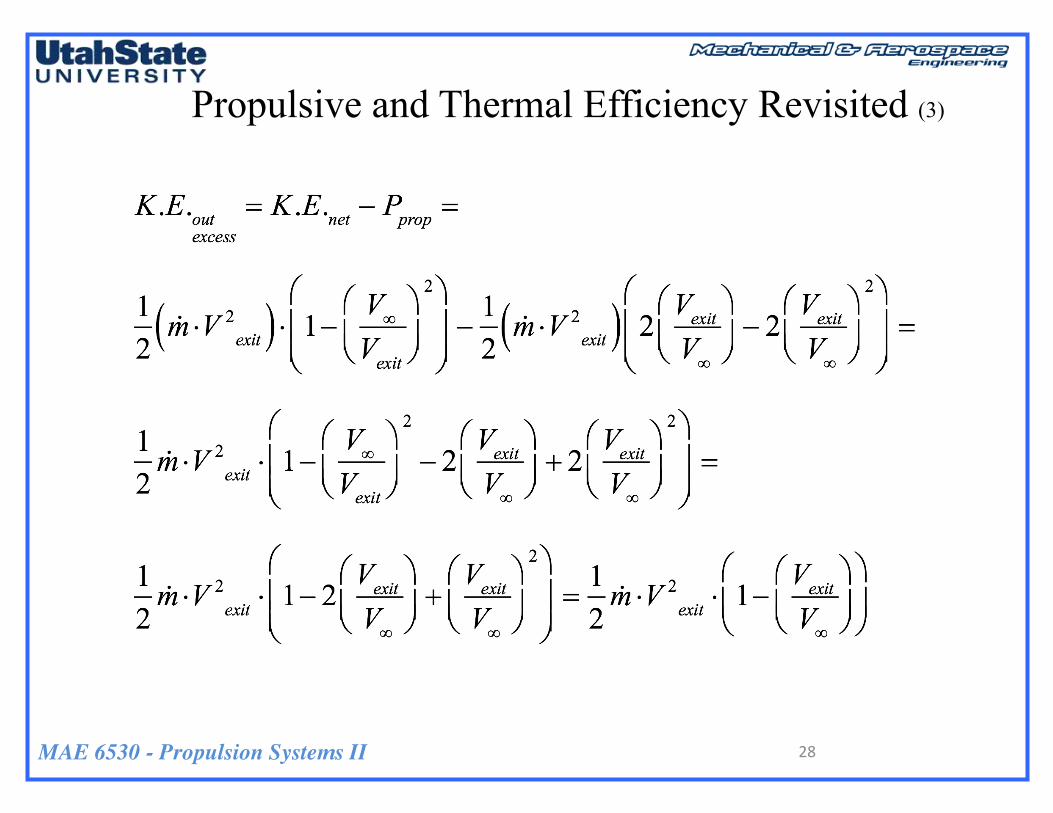
Propulsive and Thermal Efficiency Revisited (3)
28

MAE 6530 - Propulsion Systems II
Propulsive and Thermal Efficiency Revisited (9)
29
Summary
MAE 6530 - Propulsion Systems II
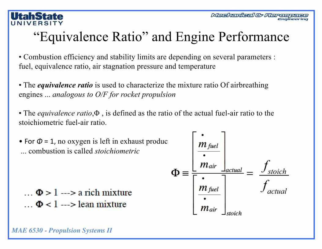
“Equivalence Ratio” and Engine Performance• Combustion efficiency and stability limits are depending on several parameters : fuel, equivalence ratio, air stagnation pressure and temperature
• The equivalence ratio is used to characterize the mixture ratio Of airbreathingengines ... analogous to O/F for rocket propulsion
• The equivalence ratio,Φ , is defined as the ratio of the actual fuel-air ratio to the stoichiometric fuel-air ratio.
•ForΦ =1,no oxygen is left in exhaust products... combustion is called stoichiometric
fstoichfactual

MAE 6530 - Propulsion Systems II
“Equivalence Ratio” and Engine Performance (2)
• Unlike Rockets .. Ramjets … and air breathing propulsion systems tend to be more efficient when engine runs leaner than stoichiometric• Also Thermal Capacity of Turbine Materials Limits Maximum Allowable Combustion Temperature, notAllowing Engine to Run Stoichiometric
Fthrustm f
•
⎛
⎝⎜⎜
⎞
⎠⎟⎟opt
=Vexit +1fVexit −V∞( )

MAE 6530 - Propulsion Systems II
“Equivalence Ratio” and Engine Performance (3)
• … that is why afterburners work … left over O2 after combustion
Additional fuel is introduced into the hot exhaust and burned using excessO2 from main combustion
• The afterburner increases the temperature of the gas ahead of the nozzle Increases exit velocity
• The result of this increase in temperature is an increase of about 40 percent in thrust at takeoff and a much larger percentage at high speeds
MAE 6530 - Propulsion Systems II
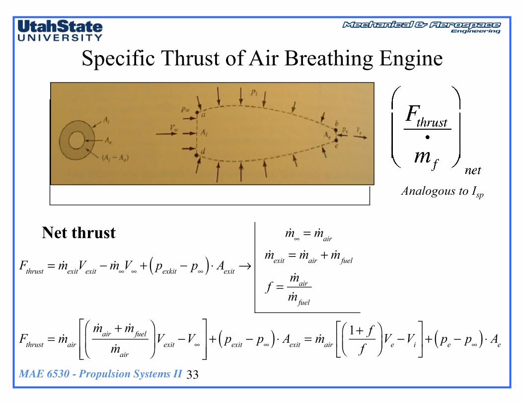
Specific Thrust of Air Breathing Engine
33
Analogous to Isp
Net thrust
Fthrust = !mexitVexit − !m∞V∞ + pexkit − p∞( ) ⋅ Aexit →!m∞ = !mair
!mexit = !mair + !mfuel
f =!mair!mfuel
Fthrust = !mair!mair + !mfuel
!mair
⎛
⎝⎜⎞
⎠⎟Vexit −V∞
⎡
⎣⎢⎢
⎤
⎦⎥⎥+ pexit − p∞( ) ⋅ Aexit = !mair 1+ f
f⎛⎝⎜
⎞⎠⎟Ve −Vi
⎡
⎣⎢
⎤
⎦⎥ + pe − p∞( ) ⋅ Ae

MAE 6530 - Propulsion Systems II
Specific Thrust of Air Breathing Engine (2)
Thrust = m•e Ve − m
•i Vi + peAe − p∞Ae( ) Cruise design condition
When pe=p∞
34%Ram Drag Reduced at lower air-fuel ratio “f”
Fthrustm f
•
⎛
⎝⎜⎜
⎞
⎠⎟⎟opt
=mf
•+mair
•⎡⎣⎢
⎤⎦⎥Vexit −mair
•V∞
mf
• = f +1[ ]Vexit − f ⋅V∞ =Vexit + f ⋅ Vexit −V∞( )
f =!mair!mfuel

MAE 6530 - Propulsion Systems II
Jet Engine Fuel Efficiency Performance MeasureThrust Specific Fuel Consumption (TSFC) à Inverse of Specific Thrust • Measure of fuel economy
• Analogous to specific impulse in Rocket Propulsion
35
TSFC generally goes up engine moves from takeoff to cruise, as energy required to produce a thrust goes up with increased percentage of stagnation pressure losses and with increased momentum of incoming air.
MAE 6530 - Propulsion Systems II
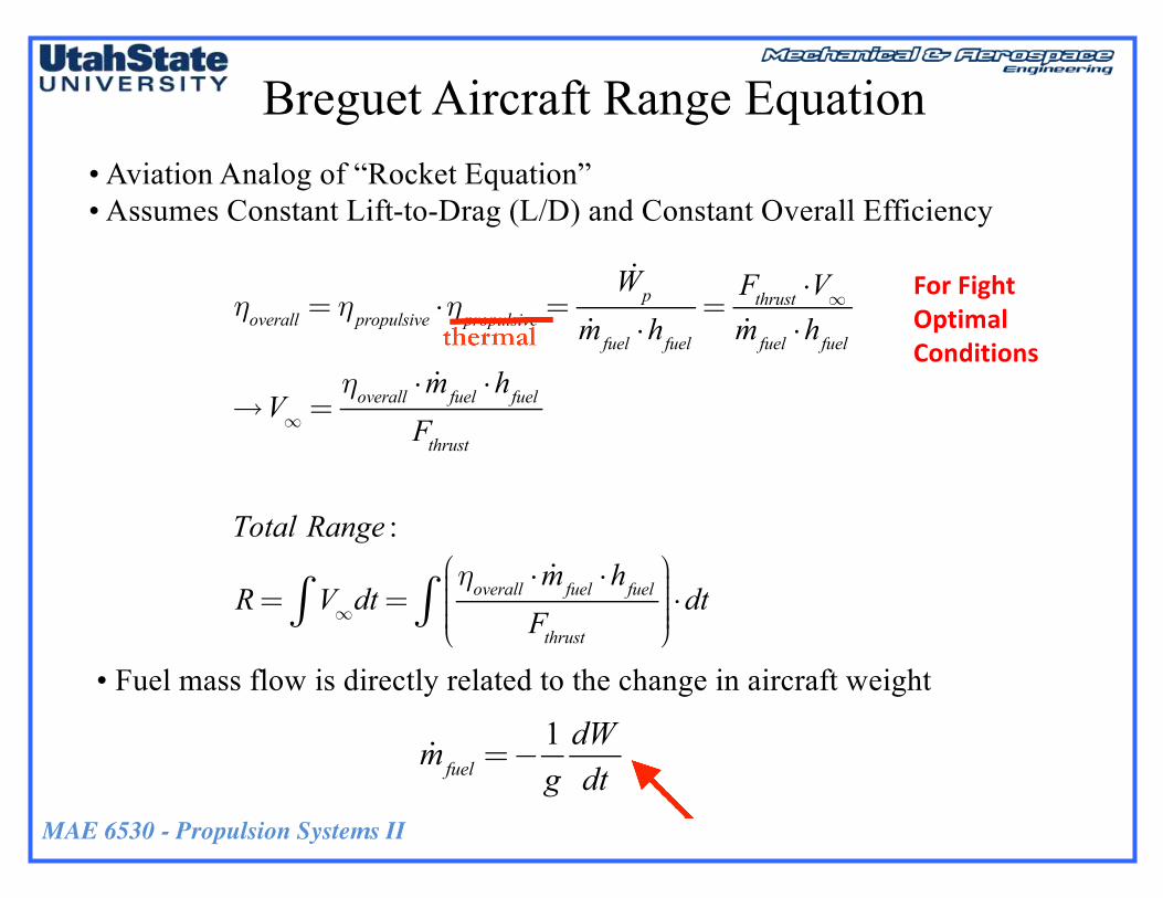
Breguet Aircraft Range Equation• Aviation Analog of “Rocket Equation”• Assumes Constant Lift-to-Drag (L/D) and Constant Overall Efficiency
ηoverall = η propulsive ⋅η propulsive =!Wp
!mfuel ⋅hfuel=Fthrust ⋅V∞!mfuel ⋅hfuel
→V∞ =ηoverall ⋅ !mfuel ⋅hfuel
Fthrust
Total Range :
R= V∞∫ dt=ηoverall ⋅ !mfuel ⋅hfuel
Fthrust
⎛
⎝⎜⎜⎜⎜
⎞
⎠
⎟⎟⎟⎟⎟∫ ⋅dt
• Fuel mass flow is directly related to the change in aircraft weight
!mfuel =−1gdWdt
ForFightOptimalConditions

MAE 6530 - Propulsion Systems II
Breguet Aircraft Range Equation (2)
• In equilibrium (cruise) flight Thrust equals drag and aircraft weight equals lift …
• Subbing into Range Equation
• Integration Gives
T = D= L / LD⎛
⎝⎜⎜⎜⎞
⎠⎟⎟⎟⎟=W /
LD⎛
⎝⎜⎜⎜⎞
⎠⎟⎟⎟⎟
R= V∞∫ dt=−ηoverall ⋅
1gdWdt⋅hfuel
W / LD
⎛
⎝⎜⎜⎜⎞
⎠⎟⎟⎟⎟
⎛
⎝
⎜⎜⎜⎜⎜⎜⎜⎜⎜⎜⎜
⎞
⎠
⎟⎟⎟⎟⎟⎟⎟⎟⎟⎟⎟⎟
∫ ⋅dt=−ηoverall ⋅hfuelg⋅LD
⎛
⎝⎜⎜⎜⎞
⎠⎟⎟⎟⎟⋅
dWW
⎛
⎝⎜⎜⎜
⎞
⎠⎟⎟⎟⎟∫
R=−ηoverall ⋅hfuelg⋅LD
⎛
⎝⎜⎜⎜⎞
⎠⎟⎟⎟⎟⋅ ln Wfinal( )− ln Winitial( )⎡⎣⎢
⎤⎦⎥= ηoverall ⋅
hfuelg⋅LD
⎛
⎝⎜⎜⎜⎞
⎠⎟⎟⎟⎟⋅ ln
Winitial
Wfinal
⎛
⎝
⎜⎜⎜⎜⎜
⎞
⎠
⎟⎟⎟⎟⎟
R= ηoverall ⋅hfuelg⋅LD
⎛
⎝⎜⎜⎜⎞
⎠⎟⎟⎟⎟⋅ ln
Winitial
Wfinal
⎛
⎝
⎜⎜⎜⎜⎜
⎞
⎠
⎟⎟⎟⎟⎟

MAE 6530 - Propulsion Systems II
Breguet Aircraft Range Equation (3)
R= ηoverall ⋅hfuelg⋅LD
⎛
⎝⎜⎜⎜⎞
⎠⎟⎟⎟⎟⋅ ln
Winitial
Wfinal
⎛
⎝
⎜⎜⎜⎜⎜
⎞
⎠
⎟⎟⎟⎟⎟
• Result highlights the key role played by the engine overall efficiency in available aircraft range.
• Note that as the aircraft burns fuel it must increase altitude to maintain constant L/D , and the required thrust decreases.
MAE 6530 - Propulsion Systems II
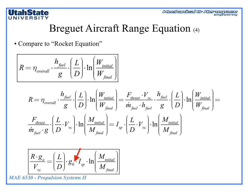
Breguet Aircraft Range Equation (4)
• Compare to “Rocket Equation”
R= ηoverall ⋅hfuelg⋅LD
⎛
⎝⎜⎜⎜⎞
⎠⎟⎟⎟⎟⋅ ln
Winitial
Wfinal
⎛
⎝
⎜⎜⎜⎜⎜
⎞
⎠
⎟⎟⎟⎟⎟
R= ηoverall ⋅hfuelg⋅LD
⎛
⎝⎜⎜⎜⎞
⎠⎟⎟⎟⎟⋅ ln
Winitial
Wfinal
⎛
⎝
⎜⎜⎜⎜⎜
⎞
⎠
⎟⎟⎟⎟⎟=Fthrust ⋅V∞!mfuel ⋅hfuel
⋅hfuelg⋅LD
⎛
⎝⎜⎜⎜⎞
⎠⎟⎟⎟⎟⋅ ln
Winitial
Wfinal
⎛
⎝
⎜⎜⎜⎜⎜
⎞
⎠
⎟⎟⎟⎟⎟=
Fthrust!mfuel ⋅g
⋅LD⋅V∞
⎛
⎝⎜⎜⎜
⎞
⎠⎟⎟⎟⎟⋅ ln
Minitial
M final
⎛
⎝
⎜⎜⎜⎜⎜
⎞
⎠
⎟⎟⎟⎟⎟= Isp ⋅
LD⋅V∞
⎛
⎝⎜⎜⎜
⎞
⎠⎟⎟⎟⎟⋅ ln
Minitial
M final
⎛
⎝
⎜⎜⎜⎜⎜
⎞
⎠
⎟⎟⎟⎟⎟
R ⋅goV∞=LD
⎛
⎝⎜⎜⎜⎞
⎠⎟⎟⎟⎟⋅g0 ⋅ Isp ⋅ ln
Minitial
M final
⎛
⎝
⎜⎜⎜⎜⎜
⎞
⎠
⎟⎟⎟⎟⎟
MAE 6530 - Propulsion Systems II
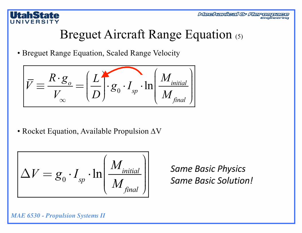
Breguet Aircraft Range Equation (5)
• Breguet Range Equation, Scaled Range Velocity
• Rocket Equation, Available Propulsion DV
V ≡R ⋅goV∞=LD
⎛
⎝⎜⎜⎜⎞
⎠⎟⎟⎟⎟⋅g0 ⋅ Isp ⋅ ln
Minitial
M final
⎛
⎝
⎜⎜⎜⎜⎜
⎞
⎠
⎟⎟⎟⎟⎟
ΔV = g0 ⋅ Isp ⋅ lnMinitial
M final
⎛
⎝
⎜⎜⎜⎜⎜
⎞
⎠
⎟⎟⎟⎟⎟SameBasicPhysicsSameBasicSolution!
MAE 6530 - Propulsion Systems II
Section 4.1 Homework
41
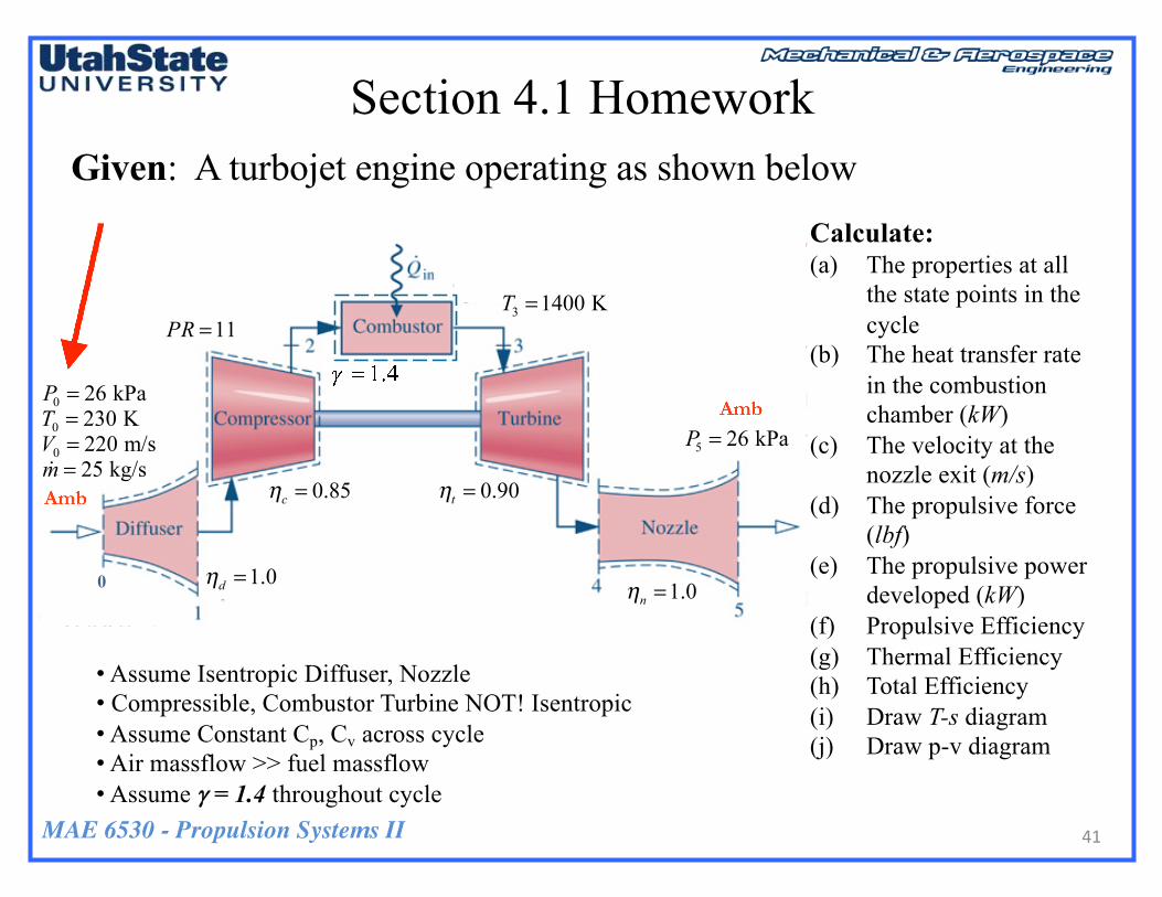
Given: A turbojet engine operating as shown belowCalculate:(a) The properties at all
the state points in the cycle
(b) The heat transfer rate in the combustion chamber (kW)
(c) The velocity at the nozzle exit (m/s)
(d) The propulsive force (lbf)
(e) The propulsive power developed (kW)
(f) Propulsive Efficiency(g) Thermal Efficiency(h) Total Efficiency(i) Draw T-s diagram(j) Draw p-v diagram
• Assume Isentropic Diffuser, Nozzle• Compressible, Combustor Turbine NOT! Isentropic• Assume Constant Cp, Cv across cycle• Air massflow >> fuel massflow• Assume g = 1.4 throughout cycle

MAE 6530 - Propulsion Systems II
Section 4.1 Homework (2)
42
Given: A turbojet engine operating as shown below
Incoming Air to Turbojet (@ to station 3)• Molecular weight = 28.96443 kg/kg-mole• = 1.40• Rg = 287.058 J/kg-K• T∞ = 230 K• p∞ = 26 kPa• V∞ = 220 m/sec• Universal Gas Constant: Ru = 8314.4612 J/kg-K
γ
For …Isentropic Conditions à
Calorically Perfect Gas
Ideal Gas
MAE 6530 - Propulsion Systems II
Section 4.1 Homework (3)
43
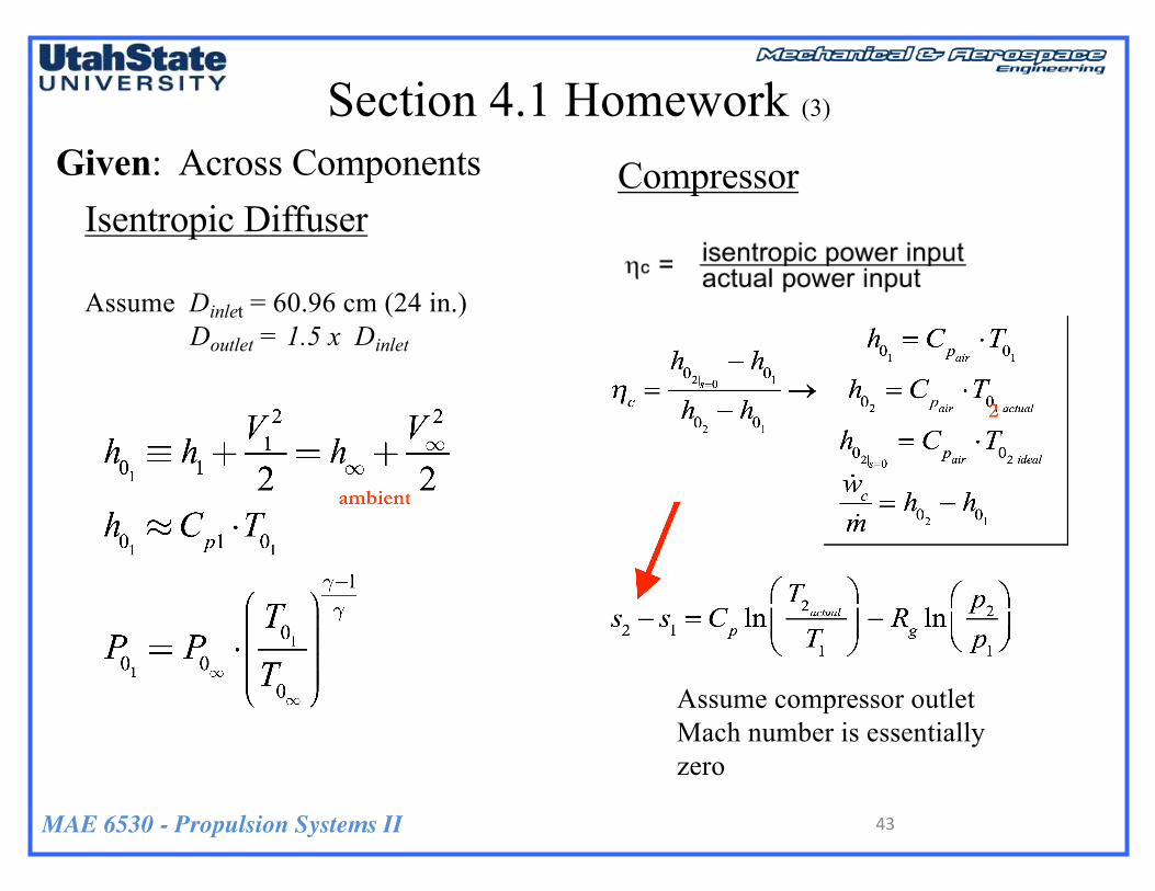
Given: Across ComponentsIsentropic Diffuser
Assume Dinlet = 60.96 cm (24 in.)Doutlet = 1.5 x Dinlet
Compressor
Assume compressor outlet Mach number is essentially zero

MAE 6530 - Propulsion Systems II
Section 4.1 Homework (4)
44
Given: Across Components
Combustor
Turbine
Assume combustor outlet Mach number is essentially zero
MAE 6530 - Propulsion Systems II45
Questions??


