79
Sewage Pumps 50Hz ®

Sewage Pumps 50Hz
®

Approvals
� ®
Contents NE Series page 4
NF Series 7
NEB(S/I) /NEBR(S/I) Series 11
NC Series 16
NWSeries 20
NWS Series 24
NAK Series 28
GPK Series 32
HE Series 36
EDW Series 44
MAM Series 48
MAL Series 52
MAK Series 60
HS Series 62
HT Series 66
NJ Series 68
ESA Series 71
ERS Series 74

NE
Seri
es -
50H
z
�
1112
6
15-1
8
28
16
21
3
4
5
7
15-2
HM
• High abrasive resistance resin Vortex impeller
• Double mechanical seal / Designed Agitator
• Auto reset thermal protector / Non air locking
• Auto version for small pit usage
NE Series • Light Weight Submersible Drainage Pump
Feature
Applications
• Residential, commercial, industrial dewatering and
site drainage
• Decorative waterfalls and fountains.
• Raw water supply from lakes or rivers.
• Sediment removal from small sumps or basins
1PH Protector (optional) (overheat & overload) 1PH Protector (Thermal)
Klixon protector provides protection against overheating from all running and stalled rotor conditions including:
» Plugging duty
» Stalling or failure to start
» Heavy overloads
» High ambient
» Ventilation failures
3PH Protector (overheat, overload)
»The additoinal suction plate can be drain water down to approx. 3mm.
Optional Suction Platetransfer to residue pump for 0.5HP
1112
6
15-1
8
28
16
21
3
4
5
7
15-2
HM
1112
6
15-1
8
28
16
21
3
4
5
7
15-2
HM
Further options
Agitator
� ®
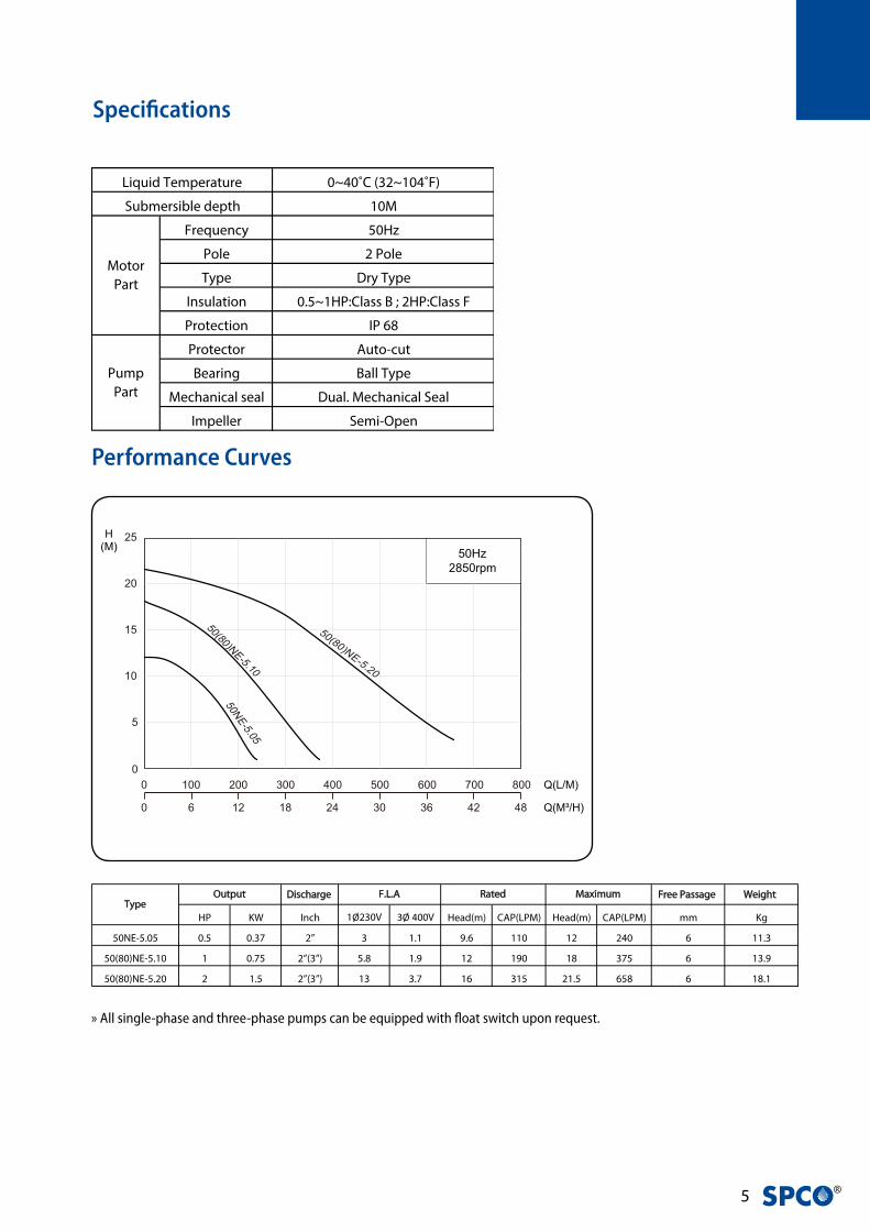
Performance Curves
Specifications
Discharge Free Passage Weight
HP KW Inch 1Ø230V 3Ø 400V Head(m) CAP(LPM) Head(m) CAP(LPM) mm Kg
50NE-5.05 0.5 0.37 2” 3 1.1 9.6 110 12 240 6 11.3
50(80)NE-5.10 1 0.75 2”(3”) 5.8 1.9 12 190 18 375 6 13.9
50(80)NE-5.20 2 1.5 2”(3”) 13 3.7 16 315 21.5 658 6 18.1
Output Rated MaximumF.L.AType
» All single-phase and three-phase pumps can be equipped with float switch upon request.
0~40˚C (32~104˚F)
10M
Frequency 50Hz
Pole 2 Pole
Type Dry Type
Insulation 0.5~1HP:Class B ; 2HP:Class F
Protection IP 68
Protector Auto-cut
Bearing Ball Type
Mechanical seal Dual. Mechanical Seal
Impeller Semi-Open
Pump
Part
Liquid Temperature
Submersible depth
Motor
Part

NF
seri
es -
50H
z
�
Materials
Dimensions
H
H2
H1
C.W.L.
L.W.L.
H3
A1 A2
A
H2
H1
H
C.W.L.
L.W.L.
H3
A2
A
A1 A2A1
A
H2
H1
H
H3
C.W.L.
L.W.L.
50NE-5.05 50(80)NE-5.10 50(80)NE-5.20
Type A A1 A2 H H1 H2 H3
50NE-5.05 243 94 117 352 200 84 110
50(80)NE-5.10 279 94 133 377 225 84 121
50(80)NE-5.20 313 107 155 464 308 94 130
1112
6
15-1
8
28
16
21
3
4
5
7
15-2
HM
No Part Material
1 Cable H07RN-F /SJTOW/STOW
2 Handle Nylon 6
3 Motor Cover ADC 12
4 Bracket Steel
5 Motor Housing + Stator ADC12+Steel
6 Shaft with Rotor AISI 410
7 Oil Chamber 0.5~1HP:Cast Iron
2HP:AlSi7Mg
8 Mech. Seal Upper : CA/CE
Lower : SIC/SIC
11 Impeller Hytrel
12 Pump Casing EN-GJL-200
15-1 Upper Bearing NTN/TPI
15-2 Lower Bearing NTN/TPI
16 Strainer PVC
28 Agitator SMF5030
� ®
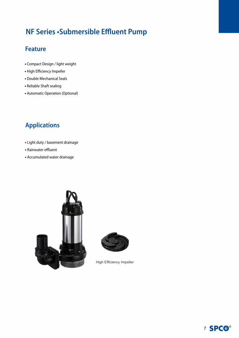
NF Series •Submersible Effluent Pump
• Light duty / basement drainage
• Rainwater effluent
• Accumulated water drainage
• Compact Design / light weight
• High Efficiency Impeller
• Double Mechanical Seals
• Reliable Shaft sealing
• Automatic Operation (Optional)
Feature
Applications

NF
seri
es -
50H
z
�
Performance Curves
Specifications
Discharge Free Passage
HP KW Inch 1Ø230V 3Ø 400V Head(m) CAP(LPM) Head(m) CAP(LPM) mm 1Ø 3Ø
50NF-5.05 0.5 0.37 2” 4.1 1.3 6 150 9.5 260 5 11.7 11.4
50NF-5.10 1 0.75 2” 5.2 2.1 8 150 11 400 5 18.5 18.2
50(80)NF-5.20 2 1.5 2”(3”) 11.3 3.5 10 400 15.5 650 5.5 35 34.9
50(80)NF-5.30 S(T) 3 2.2 2”(3”) 14 5.2 15 440 21 800 5.5 39.1 35.4
80(100)NF-5.50 5 3.7 3”(4”) - 8.2 15 530 27 950 5.5 - 53.2
80(100)NF-5.75 7.5 5.5 3”(4”) - 11.5 20 600 31 1000 5.5 - 59.2
Weight (kg)Output Rated MaximumF.L.AType
»S : Single phase, T: Three phase
» 50NF-5.05 : Thread Type
» 50NF-5.10 : Thread Type / Elbow Type is optional.(2” or 3”/ Fit with Q.D.C. QM-80)
» 50(80)NF-5.20~30 & 80(100)NF-5.50~75 : Elbow Type
0~40˚C (32~104˚F)
10M
Frequency 50Hz
Pole 2 Pole
Type Dry Motor
Insulation 0.5-3HP Class B ,5-7.5HP Class F
Protection IP 68
Protector Auto-cut
Bearing Ball Type
Mechanical seal Dual. Mechanical Seal
Impeller Semi-Open
Pump
Part
Liquid Temperature
Submersible depth
Motor
Part

� ®
Materials
www.evak-pumps.com
1
6
15
13
8
11
54
912
2
15
10
3
7
16
D
D1
D2
A1AA2
A3
H3
NF-5.05~10 NF-5.10~30 NF-5.50~75
Type A A1 A2 A3 D D1 D2 H H1 H2 H3
50NF-5.05 229 70 123 NA 141 66 75 350 250 79 100
50NF-5.10 229 70 123 NA 141 66 75 380 285 79 100
*50(80)NF-5.10 325 80 192 110 165 75 90 398 273 97 147
50(80)NF-5.20 403 103 250 168 212 103 109 555 385 110 163
50(80)NF-5.30S(T) 403 103 250 168 212 103 109 575 405 110 163
80(100)NF-5.50 466 110 264 176 227 110 117 605 440 132 220
80(100)NF-5.75 466 110 264 176 227 110 117 645 480 132 220
Dimensions
» Note1 : S: Single Phase ; T: Three Phase
»Automatic models are available in single-phase versions(0.5~2HP) and in three-phase versions(0.5~2HP).
»Q.D.C.(Quick Discharge Connection) is available only for Elbow type.
No Part Material
1 Cable H07RN-F/SJTOW/STOW
2 Handle Nylon 6 / ASTM A36
3 Motor Cover Nylon 66 / EN-GJL-200
4 Bracket EN-GJL-200
5 Motor Housing AISI 304
6 Shaft with Rotor AISI 410
7 Oil Chamber EN-GJL-200
8 Double Mech.Seal Upper : CA / CE
Lower : CA / CE(0.5~3HP)
SIC / SIC(5~7.5HP)
9 Seal Housing EN-GJL-200
10 Oil Seal NBR
11 Impeller EN-GJL-200
12 Pump Casing EN-GJL-200
13 Protector KLIXON
15 Bearing NTN/TPI
16 Strainer AISI 304

NF
seri
es -
50H
z
10
Dimensions with QDC (QM)
HH
123
8
L.W.L.
C.W.L.
129
252
8060
57 123 92
659103 474
212 10
910
3 180
150
18
180240
350
191
70
Output Discharge Dimensions(mm)
HP
1
2
3
5
7.5
kW
0.75
1.5
2.2
3.7
5.5
Inch
2”(3”)
2”(3”)
2”(3”)
3”(4”)
3”(4”)
mm
50(80)
50(80)
50(80)
80(100)
80(100)
H
610
695
S:735;T:715
765
805
H1
466
525
S:565;T:545
587
627
NF with QM Q.D.C.
ex. : 50(80)NF-5.20~30
HP KW Inch mm H H1
1 0.75 2''(3'') 50(80) 610 466
2 1.5 2''(3'') 50(80) 695 525
3 2.2 2''(3'') 50(80) S:735 ; T:715 S:565 ; T:545
5 3.7 3''(4'') 80(100) 765 587
7.5 5.5 3''(4'') 80(100) 805 627
Output Discharge Dimensions(mm)

11 ®
• Site drainage, mining, tunneling, public works,floods
• Cement industry, river intake, civil engineering projects
• Basement, parking lots, removing residue water
(NEBR/NEBRS/NEBRI)
• Version “S” in AISI 304 and “I” in AISI 316 are suitable for
• chemical liquids in drainage and general pumping applications
• High resistance to abrasive liquids
• Double mechanical seal in CA/CA+SIC/SIC
• Vortex impeller made of resin
• KLIXON thermal overload protection is available
upon request
• Compact design & Light weight
• Shaft in Stainless steel AISI 410
Applications
Feature
NEB/NEBS(I)/NEBR/NEBRS(I) Series • Submersible
Dewatering Pumps

NEB
/R S
erie
s -
50H
z
12
Specifications
Further options
1112
6
15-1
8
28
16
21
3
4
5
7
15-2
HM
1PH Protector (optional) (overheat & overload)
1PH Protector (Thermal)
Klixon protector provides protection against overheating from all running and stalled rotor conditions including:
» Plugging duty
» Stalling or failure to start
» Heavy overloads
» High ambient
» Ventilation failures
3PH Protector (overheat, overload)
1112
6
15-1
8
28
16
21
3
4
5
7
15-2
HM
0~40˚C (32~104˚F)
10M
Frequency 50Hz
Pole 2 Pole
Type Dry Motor
Insulation Class B (0.5-1HP). Class F (2HP)
Protection IP 68
Protector Auto-cut
Bearing Ball Type
Mechanical seal Dual. Mechanical Seal
Impeller Semi-Open
Pump
Part
Liquid Temperature
Submersible depth
Motor
Part

1� ®
Materials
No Part
NEB(0.5~1HP) NEB(2HP) NEBS NEBI NEBR NEBRS NEBRI
2 Handle Steel+NBR Steel+NBR AISI 304+NBR AISI 316+NBR Steel+NBR AISI 304+NBR AISI 316+NBR
3 Motor Cover ADC 12 ADC 12 AISI 304 AISI 316 ADC 12 AISI 304 AISI 316
4 Bracket Steel Steel EN-GJL-200 EN-GJL-200 Steel EN-GJL-200 EN-GJL-200
5 Motor Housing + Stator ADC12+Steel ADC12+Steel AISI 304 AISI 316 ADC12+Steel AISI 304 AISI 316
6 Shaft with Rotor AISI 410 AISI 410 AISI 304 AISI 316 AISI 410 AISI 304 AISI 316
7 Oil Chamber ADC 12 AlSi7Mg AISI 304 AISI 316 ADC 12 AISI 304 AISI 316
7-1 Oil Chamber - AlSi7Mg - - - - -
8 Mech. Seal
11 Impeller Hytrel Hytrel AISI 304 AISI 316 Hytrel AISI 304 AISI 316
12 Pump Casing EN-GJL-200 EN-GJL-200 AISI 304 AISI 316 EN-GJL-200 AISI 304 AISI 316
15-1 Upper Bearing
15-2 Lower Bearing
16 Strainer AISI 304 AISI 304 AISI 304 AISI 316 NBR EPDM EPDM
18-4 Volute Liner NBR NBR EPDM EPDM NBR EPDM EPDM
30 Pump Housing AISI 304 AISI 304 AISI 304 AISI 316 AISI 304 AISI 304 AISI 316
32 Pump Housing Ring - - - - AISI 304 AISI 304 AISI 316
Material
NTN/TPI
NTN/TPI
CA/CE+SIC/SIC
www.evak-pumps.com
4
6
3
8
11
16
30
15-2
18-412
2
5
7
15-1
32
6
7
1216
30
15-1
18-411
2
3
4
5
815-2
6
3
15-2
4
18-4
12
2
30
11
15-1
5
16
7-1 87
50NEB(S,I)-5.05~10 50NEBR(S,I)-5.05~10 50NEB-5.20
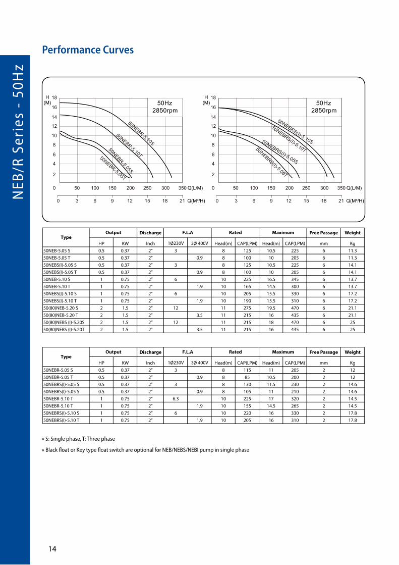
Performance Curves
NEB
/R S
erie
s -
50H
z
1�
Discharge Free Passage Weight
HP KW Inch 1Ø230V 3Ø 400V Head(m) CAP(LPM) Head(m) CAP(LPM) mm Kg
50NEB-5.05 S 0.5 0.37 2” 3 8 125 10.5 225 6 11.3
50NEB-5.05 T 0.5 0.37 2” 0.9 8 100 10 205 6 11.3
50NEBS(I)-5.05 S 0.5 0.37 2” 3 8 125 10.5 225 6 14.1
50NEBS(I)-5.05 T 0.5 0.37 2” 0.9 8 100 10 205 6 14.1
50NEB-5.10 S 1 0.75 2” 6 10 225 16.5 345 6 13.7
50NEB-5.10 T 1 0.75 2” 1.9 10 165 14.5 300 6 13.7
50NEBS(I)-5.10 S 1 0.75 2” 6 10 205 15.5 330 6 17.2
50NEBS(I)-5.10 T 1 0.75 2” 1.9 10 190 15.5 310 6 17.2
50(80)NEB-5.20 S 2 1.5 2” 12 11 275 19.5 470 6 21.1
50(80)NEB-5.20 T 2 1.5 2” 3.5 11 215 16 435 6 21.1
50(80)NEBS (I)-5.20S 2 1.5 2” 12 11 215 18 470 6 25
50(80)NEBS (I)-5.20T 2 1.5 2” 3.5 11 215 16 435 6 25
Discharge Free Passage Weight
HP KW Inch 1Ø230V 3Ø 400V Head(m) CAP(LPM) Head(m) CAP(LPM) mm Kg
50NEBR-5.05 S 0.5 0.37 2” 3 8 115 11 205 2 12
50NEBR-5.05 T 0.5 0.37 2” 0.9 8 85 10.5 200 2 12
50NEBRS(I)-5.05 S 0.5 0.37 2” 3 8 130 11.5 230 2 14.6
50NEBRS(I)-5.05 S 0.5 0.37 2” 0.9 8 105 11 210 2 14.6
50NEBR-5.10 T 1 0.75 2” 6.3 10 225 17 320 2 14.5
50NEBR-5.10 T 1 0.75 2” 1.9 10 155 14.5 265 2 14.5
50NEBRS(I)-5.10 S 1 0.75 2” 6 10 220 16 330 2 17.8
50NEBRS(I)-5.10 T 1 0.75 2” 1.9 10 205 16 310 2 17.8
Output Rated MaximumF.L.AType
TypeOutput F.L.A Rated Maximum
» S: Single phase, T: Three phase
» Black float or Key type float switch are optional for NEB/NEBS/NEBI pump in single phase
Performance Curves

1� ®
Dimensions
H
L.W.L.
H1
ØA
A1
ØA
A1
H
H1
L.W.L.
A1
ØA
H1
H
L.W.L.
ØA
A1H
H1
L.W.L.Ø
A
A1
H1
L.W.L.
H 436
50NEB-5.05~5.10 50NEB-5.20
50NEBI-5.05~5.1050(80)NEBS-5.2050NEBS-5.05~5.10
Type A A1 H H1
50NEBR-5.05 214 52 347 52
50NEBRS(I)-5.05 184 52 345 52(50)
50NEBR-5.10 214 52 372 52
50NEBRS(I)-5.10 184 52 370 52(50)
Type A A1 H H1
50NEB-5.05 188 52 345 53
50NEBS(I)-5.05 184 52 345 52
50NEB-5.10 188 52 370 53
50NEBS(I)-5.10 184 52 370 52
50(80)NEB-5.20 225 52 474 81
50(80)NEBS-5.20 225 52 455 81
Type A A1 H H1
50NEBR-5.05 214 52 347 52
50NEBRS(I)-5.05 184 52 345 52(50)
50NEBR-5.10 214 52 372 52
50NEBRS(I)-5.10 184 52 370 52(50)
Type A A1 H H1
50NEB-5.05 188 52 345 53
50NEBS(I)-5.05 184 52 345 52
50NEB-5.10 188 52 370 53
50NEBS(I)-5.10 184 52 370 52
50(80)NEB-5.20 225 52 474 81
50(80)NEBS-5.20 225 52 455 81
HH
1
L.W.L.
ØA
A1
ØA
A1
HH
1
L.W.L.
ØA
A1
H
H1
L.W.L.
50NEBR-5.05~5.10 50NEBRS-5.05~5.10 50NEBRI-5.05~5.10

NC
Ser
ies
- 50
Hz
1�
˙ • Drainage of sewage from building and school
basement etc.
˙ • Septic tank and cesspit
˙ • Wastewater treatment
˙ • Ground water drainage
• Tungsten inserts incorporated on the impeller blades to
provide shredding action
• Reliable shaft sealing provided by double mechanical seal
in Si.Ca
• Automatic operation (Optional)
Applications
Feature
NC Series •Submersible Cutter Sewage Pump

1� ®
Performance Curves
Specifications
Discharge Free Passage
HP KW Inch 1Ø230V 3Ø 400V Head(m) CAP(LPM) Head(m) CAP(LPM) mm 1Ø(Kg) 3Ø(Kg)
50NC-5.05 0.5 0.37 2” 4 1.2 6 150 9.5 300 19 12.8 12.5
50NC-5.10 1 0.75 2” 6 1.8 8 190 11 420 19 18.5 18.2
50(80)NC-5.20 2 1.5 2”(3”) 11.3 3.5 10 360 16 650 23 35.8 35.7
50(80)NC-5.30 S(T) 3 2.2 2”(3”) 14.5 5.2 14 330(440) 19(20) 700(800) 23 39.9 36.2
80(100)NC-5.50 5 3.7 3”(4”) - 8.2 15 530 24 900 28 -- 52.2
80(100)NC-5.75 7.5 5.5 3”(4”) - 11.5 21 525 30 1100 28 -- 59.2
WeightOutput Rated MaximumF.L.AType
» S: Single phase ; T: Three phase
» 50NC-5.05 : Thread Type
» 50NC-5.10 : Thread Type / Elbow Type is optional.(2” or 3” /Fit with Q.D.C. QM-80) /
»Q.D.C.(Quick Discharge Connection) is available only for Elbow type.
» 50(80)NC-5.20~30 : Elbow Type / 80(100)NC-5.50~75 : Elbow Type
0~40˚C (32~104˚F)
10M
Frequency 50Hz
Pole 2 Pole
Type Dry Motor
Insulation 0.5-3HP Class B ,5-7.5HP Class F
Protection IP 68
Protector Auto-cut
Bearing Ball Type
Mechanical seal Dual. Mechanical Seal
Impeller Semi-Open
Pump
Part
Liquid Temperature
Submersible depth
Motor
Part
NC
Ser
ies
- 50
Hz
1�
Materials
Dimensions
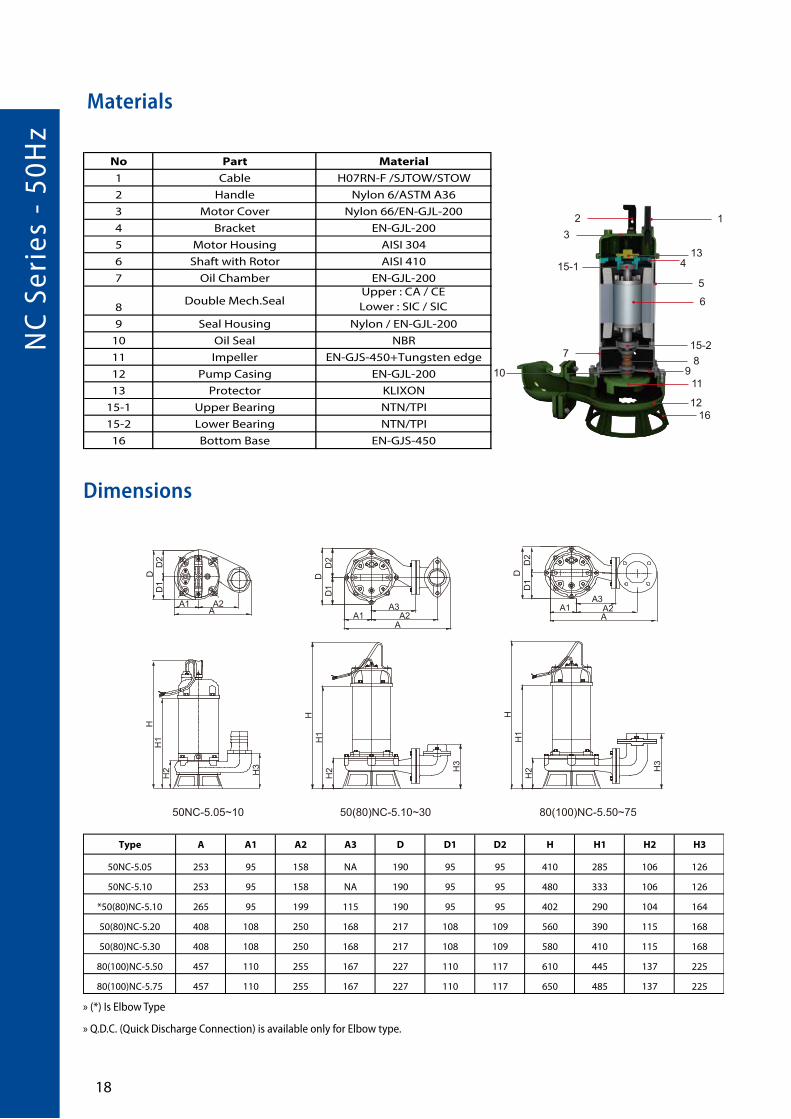
Type A A1 A2 A3 D D1 D2 H H1 H2 H3
50NC-5.05 253 95 158 NA 190 95 95 410 285 106 126
50NC-5.10 253 95 158 NA 190 95 95 480 333 106 126
*50(80)NC-5.10 265 95 199 115 190 95 95 402 290 104 164
50(80)NC-5.20 408 108 250 168 217 108 109 560 390 115 168
50(80)NC-5.30 408 108 250 168 217 108 109 580 410 115 168
80(100)NC-5.50 457 110 255 167 227 110 117 610 445 137 225
80(100)NC-5.75 457 110 255 167 227 110 117 650 485 137 225
HD
AA2A1
D1
D2
H1
H2 H3
DD
2D
1
A1 A2A3
A
HH
1H
2 H3
HH
1H
2 H3
DD
1D
2
A1AA2
A3
50NC-5.05~10 50(80)NC-5.10~30 80(100)NC-5.50~75
1
6
15-2
13
8
11
5
4
9
1216
2
15-1
10
3
7
» (*) Is Elbow Type
» Q.D.C. (Quick Discharge Connection) is available only for Elbow type.
No Part Material
1 Cable H07RN-F /SJTOW/STOW
2 Handle Nylon 6/ASTM A36
3 Motor Cover Nylon 66/EN-GJL-200
4 Bracket EN-GJL-200
5 Motor Housing AISI 304
6 Shaft with Rotor AISI 410
7 Oil Chamber EN-GJL-200
8Double Mech.Seal
Upper : CA / CE
Lower : SIC / SIC
9 Seal Housing Nylon / EN-GJL-200
10 Oil Seal NBR
11 Impeller EN-GJS-450+Tungsten edge
12 Pump Casing EN-GJL-200
13 Protector KLIXON
15-1 Upper Bearing NTN/TPI
15-2 Lower Bearing NTN/TPI
16 Bottom Base EN-GJS-450

1� ®
Dimensions with QDC (QM)
HP KW Inch mm H H1
1 0.75 2''(3'') 50(80) 610 466
2 1.5 2''(3'') 50(80) 695 525
3 2.2 2''(3'') 50(80) S:735 ; T:715 S:565 ; T:545
5 3.7 3''(4'') 80(100) 765 587
7.5 5.5 3''(4'') 80(100) 805 627
Output Discharge Dimensions(mm)

NW
Ser
ies
- 50
Hz
20
NW Series •Submersible Vortex Sewage pump
• Medium concentration wastewater
• Heavy duty
• Vortex Impeller/Non-clogging
• Minimized abrasive wear
• Large impeller clearance
• Maintenance free
• Double Mech. Seal
Applications
Feature
21 ®
Discharge Free Passage
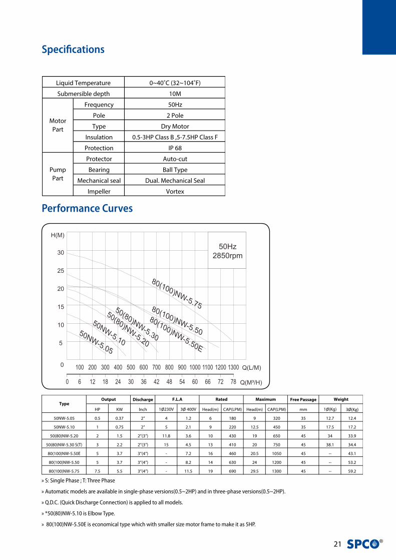
HP KW Inch 1Ø230V 3Ø 400V Head(m) CAP(LPM) Head(m) CAP(LPM) mm 1Ø(Kg) 3Ø(Kg)
50NW-5.05 0.5 0.37 2” 4 1.2 6 180 9 320 35 12.7 12.4
50NW-5.10 1 0.75 2” 5 2.1 9 220 12.5 450 35 17.5 17.2
50(80)NW-5.20 2 1.5 2”(3”) 11.8 3.6 10 430 19 650 45 34 33.9
50(80)NW-5.30 S(T) 3 2.2 2”(3”) 15 4.5 13 410 20 750 45 38.1 34.4
80(100)NW-5.50E 5 3.7 3”(4”) - 7.2 16 460 20.5 1050 45 -- 43.1
80(100)NW-5.50 5 3.7 3”(4”) - 8.2 14 630 24 1200 45 -- 53.2
80(100)NW-5.75 7.5 5.5 3”(4”) - 11.5 19 690 29.5 1300 45 -- 59.2
WeightOutput Rated MaximumF.L.AType
Performance Curves
Specifications
» S: Single Phase ; T: Three Phase
» Automatic models are available in single-phase versions(0.5~2HP) and in three-phase versions(0.5~2HP).
» Q.D.C. (Quick Discharge Connection) is applied to all models.
» *50(80)NW-5.10 is Elbow Type.
» 80(100)NW-5.50E is economical type which with smaller size motor frame to make it as 5HP.
0~40˚C (32~104˚F)
10M
Frequency 50Hz
Pole 2 Pole
Type Dry Motor
Insulation 0.5-3HP Class B ,5-7.5HP Class F
Protection IP 68
Protector Auto-cut
Bearing Ball Type
Mechanical seal Dual. Mechanical Seal
Impeller Vortex
Pump
Part
Liquid Temperature
Submersible depth
Motor
Part

NW
Ser
ies
- 50
Hz
22
HD
AA1 A2
D1
D2
H1
H2 H
3
HD
A1 A2A
A3
D1
D2
H1
H2 H3
DD
1D
2
A1AA2
A3
HH
1H
2
H3
NW-5.05~10 NW-5.10~30 NW-5.50~75NW-5.50E
Type A A1 A2 A3 D D1 D2 H H1 H2 H3
50NW-5.05 228 73 155 NA 150 69 81 412 297 117 138
50NW-5.10 228 73 155 NA 150 69 81 487 345 117 138
*50(80)NW-5.10 312 82 183 101 163 76 87 494 351 124 156
50(80)NW-5.20 390 103 235 151 210 105 105 532 400 150 152
50(80)NW-5.30 390 103 235 151 210 105 105 552 420 150 152
80(100)NW-5.50E 440 105 240 150 180 85 95 622 450 155 227
80(100)NW-5.50 470 110 257 170 218 98 120 633 468 160 206
80(100)NW-5.75 470 110 257 170 218 98 120 673 508 160 206
6
1
15-2
13
8
11
5
4
12
2
15-1
10
3
7
9
Materials
Dimensions
Note: * Is Elbow Type
No Part Material
1 Cable H07RN-F/SJTOW/STOW
2 Handle Nylon 6/ASTM A36
3 Motor Cover Nylon 66 / EN-GJL-200
4 Bracket EN-GJL-200
5 Motor Housing AISI 304
6 Shaft with Rotor AISI 410
7 Oil Chamber EN-GJL-200
8 Double Mech.Seal
Upper : CA / CE
Lower : SIC / SIC
9 Seal Housing EN-GJL-200
10 Oil Seal NBR
11 Impeller EN-GJL-200
12 Pump Casing EN-GJL-200
13 Protector KLIXON
15-1 Upper Bearing NTN/TPI
15-2 Lower Bearing NTN/TPI

2� ®
Dimensions with QDC (QS)/ QM
8169
150
73 243 75427
HH
114
022
228
30
80
C.W.L.
L.W.L.
21.5
13
110
60.5
12180
InstallationDimensions
105
105
6156
252
150
70
L.W.L.
C.W.L.
210
105 457620
134
265
H1
H
286 180
18 18
180
24
88
120
10.515
0
180InstallationDimensions
Output Discharge Dimensions(mm)HP0.51
kW0.370.75
Inch2”2”
mm5050
H434509
H1319367
Output Discharge Dimensions(mm)HP1235
5(E)7.5
kW0.751.52.23.73.75.5
Inch2”
2”(3”)2”(3”)3”(4”)3”(4”)3”(4”)
mm50
50(80)50(80)
80(100)80(100)80(100)
H625715
S:755;T:735775737815
H1482545
S:585;T:565597565637
NW with QS Q.D.C NW with QM Q.D.C
ex. : 50NW-5.05~10ex. : 50(80)NW-5.20~30
HP KW Inch mm H H1
1 0.75 2'' 50 625 482
2 1.5 2''(3'') 50(80) 715 545
3 2.2 2''(3'') 50(80) S:755 ; T:735 S:585 ; T:565
5 3.7 3''(4'') 80(100) 775 597
5 ( E ) 3.7 3''(4'') 80(100) 737 565
7.5 5.5 3''(4'') 80(100) 815 637
Output Discharge Dimensions(mm)
HP KW Inch mm H H1
0.5 0.37 2'' 50 434 319
1 0.75 2'' 50 509 367
Output Discharge Dimensions(mm)

NW
S Se
ries
- 5
0Hz
2�
NWS Series •SS316 Submersible Vortex Sewage pump
• Medium concentration wastewater
• Heavy duty
• Vortex Impeller/Non-clogging
• Minimized abrasive wear
• Large impeller clearance
• Maintenance free
• Double Mech. Seal
• Loss wax 316 stainless steel
Applications
Feature
Vortex Impeller 316 Stainless Steel
50NWS-5.05~10
50(80)NWS-5.20~30 80(100)NWS-5.50~75
Vortex ImpellerStainless Steel AISI 316
Mechanical Seal(EKK Eagle Burgmann) Long life Bearing
SQS(0.5HP~1HP)AISI 316
Gaskets, O-rings, Lip seal and Cable gland
made in Viton material
SQM(2HP~7.5HP)AISI 316
2� ®
Discharge Free Passage
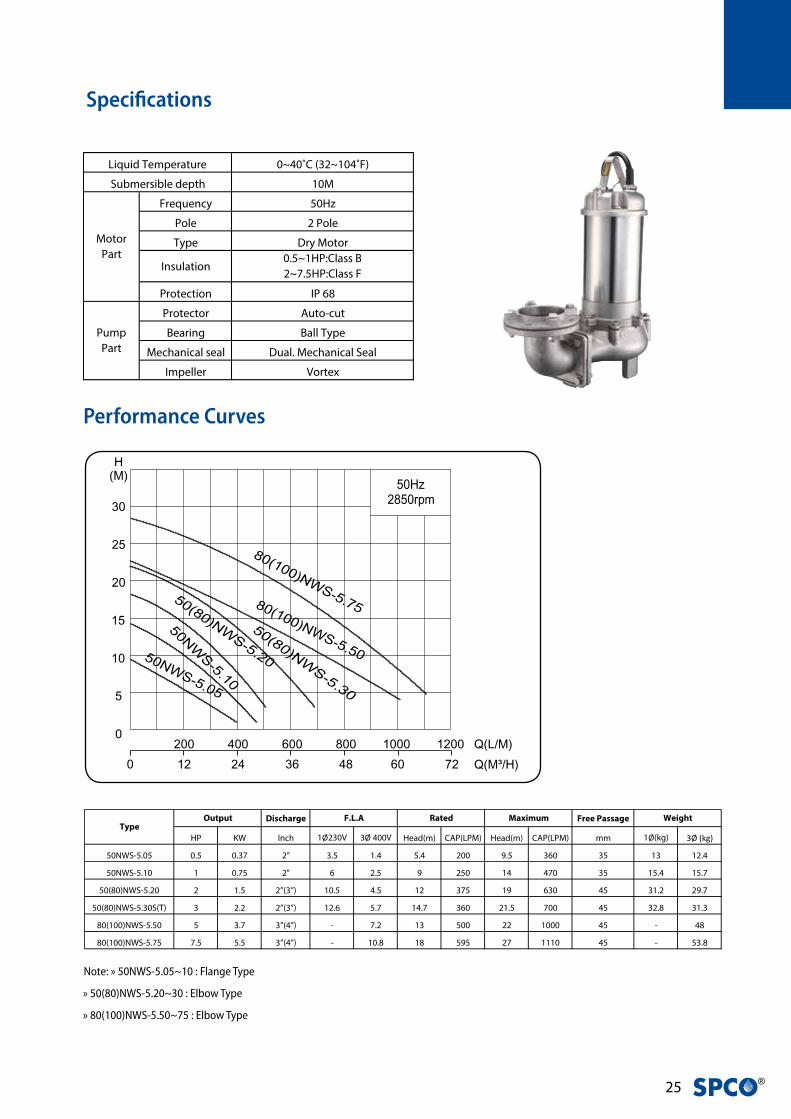
HP KW Inch 1Ø230V 3Ø 400V Head(m) CAP(LPM) Head(m) CAP(LPM) mm 1Ø(kg) 3Ø (kg)
50NWS-5.05 0.5 0.37 2” 3.5 1.4 5.4 200 9.5 360 35 13 12.4
50NWS-5.10 1 0.75 2” 6 2.5 9 250 14 470 35 15.4 15.7
50(80)NWS-5.20 2 1.5 2”(3”) 10.5 4.5 12 375 19 630 45 31.2 29.7
50(80)NWS-5.30S(T) 3 2.2 2”(3”) 12.6 5.7 14.7 360 21.5 700 45 32.8 31.3
80(100)NWS-5.50 5 3.7 3”(4”) - 7.2 13 500 22 1000 45 - 48
80(100)NWS-5.75 7.5 5.5 3”(4”) - 10.8 18 595 27 1110 45 - 53.8
Discharge Free Passage Weight
HP KW Inch 1Ø230V 3Ø 400V Head(m) CAP(LPM) Head(m) CAP(LPM) mm Kg
40NWSS-5.07 0.75 0.55 1 1/2” 3.58 1.33 7.1 80 9.1 260 35 8.97
40NWSS-5.07A 0.75 0.55 1 1/2” 3.58 - 7.1 80 9.1 260 35 9.21
50NWSS-5.10 1 0.75 2'' 4.78 2.07 7.1 100 7.7 400 50 11.78
50NWSS-5.10A 1 0.75 2'' 4.78 - 7.1 100 7.7 400 50 12.05
50NWSS-5.15 1.5 1.1 2'' 7.21 2.48 8.6 100 9.1 450 50 13.06
50NWSS-5.15A 1.5 1.1 2'' 7.21 - 8.6 100 9.1 450 50 13.32
50NWSS-5.20 2 1.5 2'' - 3.31 10.2 150 11 550 50 13.73
Weight
TypeOutput F.L.A Rated Maximum
Output Rated MaximumF.L.AType
Performance Curves
Specifications
Note: » 50NWS-5.05~10 : Flange Type
» 50(80)NWS-5.20~30 : Elbow Type
» 80(100)NWS-5.50~75 : Elbow Type
Al l technical informat ion is subject to change without not ice.
1
6
15-2
13
8
11
5
4
9
12
2
15-1
10
3
7
8170
150
75 243 71415
HH
114
226
.5
228
30
80
C.W.L.
L.W.L.
21.5
13
110
60.5
12180
InstallationDimensions
ex. : 50EWS-5.05~10
104
104
6156
250
150
70
L.W.L.
C.W.L.
208
104 455610
134
253
H1
H
285 181
18 18
180
24 88
121
10.515
0
181InstallationDimensions
ex. : 50(80)EWS-5.20~30
NWS with SQS NWS with SQM
0~40˚C (32~104˚F)
10M
Frequency 50Hz
Pole 2 Pole
Type Dry Motor
Insulation0.5~1HP:Class B
2~7.5HP:Class F
Protection IP 68
Protector Auto-cut
Bearing Ball Type
Mechanical seal Dual. Mechanical Seal
Impeller Vortex
0~35˚C (32~95˚F)
5M
Frequency 50Hz
Pole 2 Pole
Type Dry Motor
Insulation Class F
Protection IP 68
Protector Thermal Protector (1PH)
Bearing Double-shielded Ball Type
Mechanical seal Dual. Mechanical Seal
Impeller Vortex
Submersible depth
Motor
Part
Pump
Part
Pump
Part
Liquid Temperature
Submersible depth
Motor
Part
Liquid Temperature
NW
S Se
ries
- 5
0Hz
2�
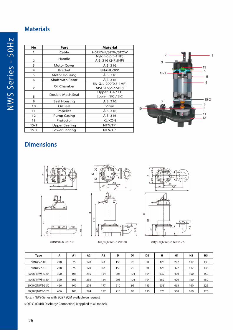
Note: » NWS-Series with SQS / SQM available on request
» Q.D.C. (Quick Discharge Connection) is applied to all models.
Materials
Dimensions
Type A A1 A2 A3 D D1 D2 H H1 H2 H3
50NWS-5.05 228 75 120 NA 150 70 80 425 297 117 138
50NWS-5.10 228 75 120 NA 150 70 80 425 327 117 138
50(80)NWS-5.20 390 103 235 154 208 104 104 532 400 150 150
50(80)NWS-5.30 390 103 235 154 208 104 104 552 420 150 150
80(100)NWS-5.50 466 100 274 177 210 95 115 633 468 160 225
80(100)NWS-5.75 466 100 274 177 210 95 115 673 508 160 225
1Ø 3Ø
40NWSS-5.07 410 410 95 -- -- -- 198
40NWSS-5.07A 410 -- 95 490 192 350 198
50NWSS-5.10 493 443 118.5 -- -- -- 198
50NWSS-5.10A 493 -- 118.5 573 275 350 198
50NWSS-5.15 493 493 118.5 -- -- -- 198
50NWSS-5.15A 493 -- 118.5 573 275 350 198
50NWSS-5.20 -- 493 118.5 -- -- -- 198
CH
Type H1 H2 H3 L
HD
AA1 A2
D1
D2
H1
H2 H
3
DD
1D
2
A1AA2
A3
H
H1
H2
HD
A1 A2A
A3
D1
D2
H1
H2 H3 H3
80(100)NWS-5.50~5.7550NWS-5.05~10 50(80)NWS-5.20~30
Al l technical informat ion is subject to change without not ice.
1
6
15-2
13
8
11
5
4
9
12
2
15-1
10
3
7
8170
150
75 243 71415
HH
114
226
.5
228
30
80
C.W.L.
L.W.L.
21.5
13
110
60.5
12180
InstallationDimensions
ex. : 50EWS-5.05~10
104
104
6156
250
150
70
L.W.L.
C.W.L.
208
104 455610
134
253
H1
H
285 181
18 18
180
24 88
121
10.515
0
181InstallationDimensions
ex. : 50(80)EWS-5.20~30
NWS with SQS NWS with SQM
No Part Material
1 Cable H07RN-F/SJTW/STOW
2Handle
Nylon 6(0.5-1HP)AISI 316 (2-7.5HP)
3 Motor Cover ÀISI 316
4 Bracket EN-GJL-200
5 Motor Housing ÀISI 316
6 Shaft with Rotor ÀISI 316
7Oil Chamber
EN-GJL-200(0.5-1HP) AISI 316(2-7.5HP)
8Double Mech.Seal
Upper : CA / CE Lower : SIC / SIC
9 Seal Housing ÀISI 316
10 Oil Seal Viton
11 Impeller ÀISI 316
12 Pump Casing ÀISI 316
13 Protector KLIXON
15-1 Upper Bearing NTN/TPI
15-2 Lower Bearing NTN/TPI

2� ®
Dimensions with QDC (SQS/SQM)
HP kW inch
0.51
0.370.75
2”2”
mm H H1
5050
445475
322352
HP kW inch
235
7.5
1.52.23.75.5
2”(3”)2”(3”)3”(4”)3”(4”)
mm H H1
50(80)50(80)
80(100)80(100)
660S:710;T:690
769809
534S:574;T:554
604644
8170
150
75 243 71415
HH
114
226
.5
228
30
80
C.W.L.
L.W.L.
21.5
13
110
60.5
12180
InstallationDimensions
104
104
6156
250
150
70
L.W.L.
C.W.L.
208
104 455610
134
253
H1
H
285 181
18 18
180
24 88
121
10.515
0
181InstallationDimensions
Output Discharge Dimensions(mm)Output Discharge Dimensions(mm)
NWS with SQS NWS with SQM
ex. : 50(80)NWS-5.20~30
ex. : 50NWS-5.05~10
HP kW inch
0.51
0.370.75
2”2”
mm H H1
5050
445475
322352
HP kW inch
235
7.5
1.52.23.75.5
2”(3”)2”(3”)3”(4”)3”(4”)
mm H H1
50(80)50(80)
80(100)80(100)
660S:710;T:690
769809
534S:574;T:554
604644
8170
150
75 243 71415
HH
114
226
.5
228
30
80
C.W.L.
L.W.L.
21.5
13
110
60.5
12180
InstallationDimensions
104
104
6156
250
150
70
L.W.L.
C.W.L.
208
104 455610
134
253
H1
H
285 181
18 18
180
24 88
121
10.515
0
181InstallationDimensions
Output Discharge Dimensions(mm)Output Discharge Dimensions(mm)
NWS with SQS NWS with SQM
ex. : 50(80)NWS-5.20~30
ex. : 50NWS-5.05~10
HP KW Inch mm H H1
2 1.5 2''(3'') 50(80) 660 534
3 2.2 2''(3'') 50(80) S:710 ; T:690 S:574 ; T:554
5 3.7 3''(4'') 80(100) 769 604
7.5 5.5 3''(4'') 80(100) 809 644
Output Discharge Dimensions(mm)
HP KW Inch mm H H1
0.5 0.37 2'' 50 445 322
1 0.75 2'' 50 475 352
Output Discharge Dimensions(mm)

NA
K S
erie
s -
50H
z
2�
NAK Series •Submersible Dredging Pumps
Dredging
Light slurry
• Vortex impeller with agitator
• Non-Colg operation
• Double mechanical seals in Si. Ca
• Reliable shaft sealing
• Automatic operation (Optional)
Applications
Feature
2� ®
Performance Curves
Specifications
Discharge Free Passage
HP KW Inch 1Ø230V 3Ø 400V Head(m) CAP(LPM) Head(m) CAP(LPM) mm 1Ø(Kg) 3Ø (Kg)
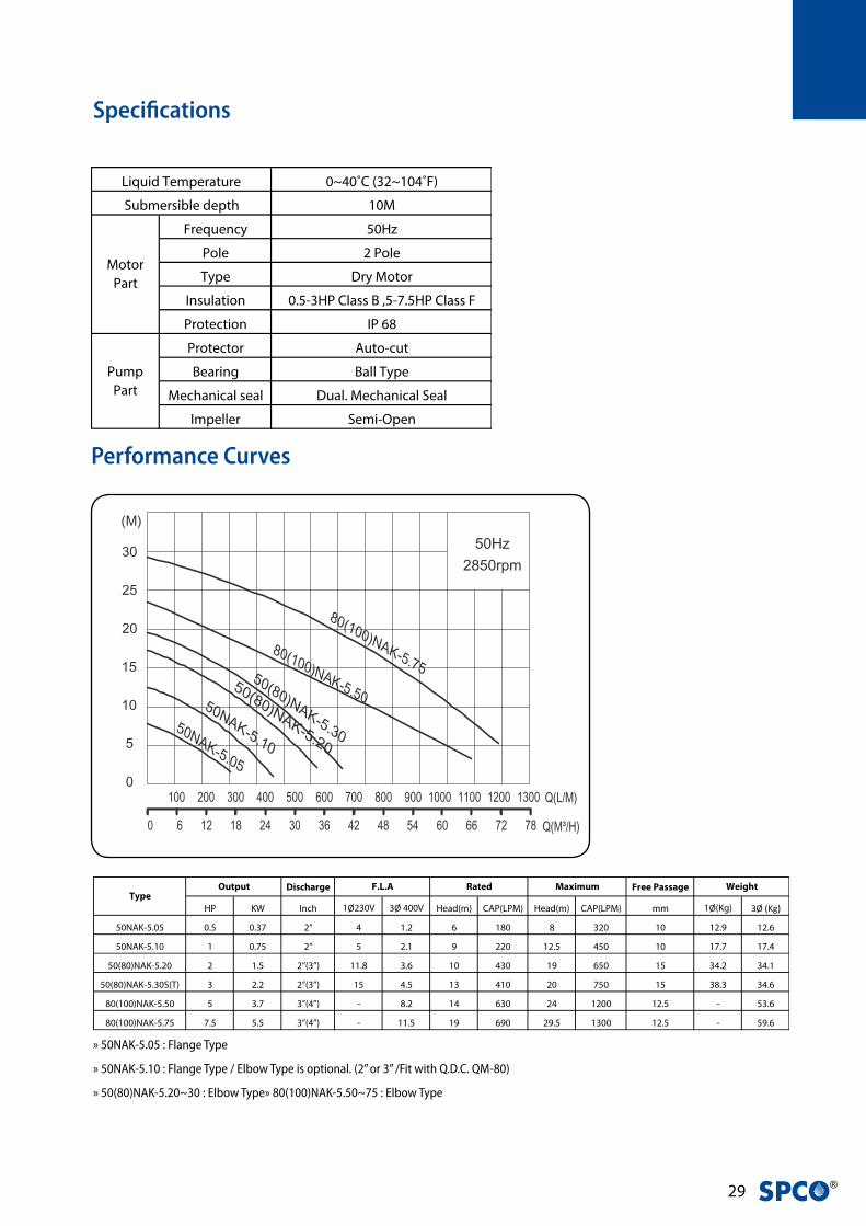
50NAK-5.05 0.5 0.37 2” 4 1.2 6 180 8 320 10 12.9 12.6
50NAK-5.10 1 0.75 2” 5 2.1 9 220 12.5 450 10 17.7 17.4
50(80)NAK-5.20 2 1.5 2”(3”) 11.8 3.6 10 430 19 650 15 34.2 34.1
50(80)NAK-5.30S(T) 3 2.2 2”(3”) 15 4.5 13 410 20 750 15 38.3 34.6
80(100)NAK-5.50 5 3.7 3”(4”) - 8.2 14 630 24 1200 12.5 - 53.6
80(100)NAK-5.75 7.5 5.5 3”(4”) - 11.5 19 690 29.5 1300 12.5 - 59.6
WeightOutput Rated MaximumF.L.AType
» 50NAK-5.05 : Flange Type
» 50NAK-5.10 : Flange Type / Elbow Type is optional. (2” or 3” /Fit with Q.D.C. QM-80)
» 50(80)NAK-5.20~30 : Elbow Type» 80(100)NAK-5.50~75 : Elbow Type
0~40˚C (32~104˚F)
10M
Frequency 50Hz
Pole 2 Pole
Type Dry Motor
Insulation 0.5-3HP Class B ,5-7.5HP Class F
Protection IP 68
Protector Auto-cut
Bearing Ball Type
Mechanical seal Dual. Mechanical Seal
Impeller Semi-Open
Pump
Part
Liquid Temperature
Submersible depth
Motor
Part

NA
K S
erie
s -
50H
z
�0
Materials
Dimensions
Type A A1 A2 A3 D D1 D2 H H1 H2 H3
50NAK-5.05 228 73 155 NA 150 69 81 412 297 117 138
50NAK-5.10 228 73 155 NA 150 69 81 487 345 117 138
50(80)NAK-5.10 312 82 183 101 163 76 87 494 351 124 156
50(80)NAK-5.20 390 103 235 151 210 105 105 532 400 150 152
50(80)NAK-5.30 390 103 235 151 210 105 105 552 420 150 152
80(100)NAK-5.50 470 110 257 170 218 98 120 633 468 160 206
80(100)NAK-5.75 470 110 257 170 218 98 120 673 508 160 206
SERIES 50HZEA
Submersible Dredging Pump
D
D1
D2
A1AA2
A3
H
H1
H2
H3
50NAK-5.05~10 50NAK-5.10~30 50NAK-5.50~5.75
Al l technical informat ion is subject to change without not ice.
1
6
13
8
11
5
4
9
12
2
15-1
10
3
715-2
No Part Material
1 Cable H07RN-F /SJTOW/STOW
2 Handle Nylon 6/SS41
3 Motor Cover Nylon 66/FC 200
4 Bracket FC 200
5 Motor Housing SUS 304
6 Shaft with Rotor SUS 410
7 Oil Chamber FC 200
8Double Mech.Seal
Upper : CA / CE
Lower : SIC / SIC
9 Seal Housing Nylon / FC 200
10 Oil Seal NBR
11 Impeller with Agitator Impeller : FC 200
Agitator : SUS 316
12 Pump Casing FC 200
13 Protector KLIXON
15-1 Upper Bearing TPI
15-2 Lower Bearing TPI
» Q.D.C. (Quick Discharge Connection) is applied to all models.

�1 ®
Dimensions with QDC ( QS/QM)
HP KW Inch mm H H1
1 0.75 2'' 50 625 482
2 1.5 2''(3'') 50(80) 715 545
3 2.2 2''(3'') 50(80) S:755 ; T:735 S:585 ; T:565
5 3.7 3''(4'') 80(100) 775 597
7.5 5.5 3''(4'') 80(100) 815 637
Output Discharge Dimensions(mm)
HP KW Inch mm H H1
0.5 0.37 2'' 50 434 319
1 0.75 2'' 50 509 367
Output Discharge Dimensions(mm)

GPK
Ser
ies
- 50
Hz
�2
GPK Series •Submersible Grinder Pumps
• Waste water treatment
• Sewage water
• Drainage of wastewater from individual residences,apartment buildings, recreational developments,motels.
• Transferring wastewater, Schools, federal, state and local parks
• To transfer various wastewater and sewage
• Robust construction
• Superior Heat Dissipation
• Double mechanical seals in Sic / Sic
• Vortex impeller design prevents clogging by cutting up articles
• Radial cutter and cutter ring SUS440C : corrosion resistant material, hardened to 55-60 Rockwell C.
• Specific single phase design for starting torque, torque is five times stronger than General capacitor pump.
• Horizontal casing with female thread can be fit the pipe directly
• Build in run / start capacitor
Applications
Feature
www.evak-pumps.com
Semi-open Impeller
QDC:QG 32GPK-5.20
CutterSUS 440C / HRC55~60
www.evak-pumps.com
Semi-open Impeller
QDC:QG 32GPK-5.20
CutterSUS 440C / HRC55~60
www.evak-pumps.com
Semi-open Impeller
QDC:QG 32GPK-5.20
CutterSUS 440C / HRC55~60

�� ®
Performance Curves
Specifications
Discharge Cable Weight
HP KW Inch 1Ø230V 3Ø 400V Head(m) CAP(LPM) Head(m) CAP(LPM) M Kg
32GPK-5.15 1.5 1.1 1-1/4"” 8.8 3.3 15.5 90 21 160 10 30
32GPK-5.20 2 1.5 1-1/4"” 11.2 4.5 23 100 28.5 160 10 32.8
32GPK-5.30 3 2.2 1-1/4"” - 4.7 25 120 31 160 10 35
50GpK-5.50 5 3.7 2” - 8.7 26 250 37 300 10 44
50GPK-5.75 7.5 5.5 2” - 11.8 36 250 46 300 10 49
Output Rated MaximumF.L.AType
0~40˚C (32~104˚F)
10M
Frequency 50Hz
Pole 2 Pole
Type Dry Motor
Insulation 1.5~3HP:Class B ;5~7.5HP:Class F
Protection IP 68
Protector Auto-cut
Bearing Ball Type
Mechanical seal Dual. Mechanical Seal
Impeller Semi-Open
Pump
Part
Liquid Temperature
Submersible depth
Motor
Part

GPK
Ser
ies
- 50
Hz
��
Materials
No Part Material
1 Cable H07RN-F/SJTOW/STOW
2 Handle ASTM A36
3 Motor Cover EN-GJL-200
4 Bracket EN-GJL-200
5 Motor Housing EN-GJL-200
6 Shaft with Rotor AISI 410
7 Oil Chamber EN-GJL-200
8 Mech. Seal Upper:CA/CE/NBR
Lower:SIC/SIC/NBR
9 Seal Housing EN-GJL-200
11 Impeller EN-GJL-200
12 Pump Casing EN-GJL-200
14-1 Upper Bearing NTN/TPI
14-2 Lower Bearing NTN/TPI
15-1 Run Capacitor 1 Phase only
15-2 Start Capacitor 1 Phase only
17 Centrifugal switch 1 Phase only
18 Cutter Set AISI 440C
www.evak-pumps.com
2
4
31
6
7
1211
3
14-1
15-1
5
8
18
9
14-2
1
15-217
Thermal protector for 1 phase
Overload protector for 3 phase
Run Capacitor(Single Phase Only)
Start Capacitor(Single Phase Only)
Centrifugal switch(Single Phase Only)
Dimensions
Type A B C D E F G H H1 H2 K K1 K2 K3 K4
32GPK-5.15(QG) 128 102 103 103 230 206 445 640 445 160 630 432 150 50 240
32GPK-5.20(QG) 128 102 103 103 230 206 445 640 445 160 630 432 150 50 240
32GPK-5.30(QG) 128 102 103 103 230 206 445 680 485 160 670 472 150 50 240
50GPK-5.50(QG) 164 119 125 114 283 239 500 669 509 186 637 477 154 29 240
50GPK-5.75(QG) 164 119 125 114 283 239 500 709 549 186 677 51 154 29 240
Dimensions (mm)
HH
1H
2
FC
D
E
B A
K2K1
K
K3
K4
G
K4
K2K1
K
K3
HH
1
H2
FC
D
EB A
G
GPK-5.15~30 GPK-5.15~30 with QG Q.D.C. GPK-5.50~75 GPK-5.50~75 with QG Q.D.C.
» (QG) identifies GPK pump with QG Q.D.C.
» Q.D.C. (Quick Discharge Connection) is applied to all models.

�� ®
www.evak-pumps.com
2
4
31
6
7
1211
3
14-1
15-1
5
8
18
9
14-2
1
15-217
Thermal protector for 1 phase
Overload protector for 3 phase
Run Capacitor(Single Phase Only)
Start Capacitor(Single Phase Only)
Centrifugal switch(Single Phase Only)
Sectional view

HE
Seri
es -
50H
z
��
HE Series •SOLID FULL-PASSAGE SEWAGE PUMP
• For heavy-duty applications with soiled biological
wastewaters, sewage, rainwater
• For both domestic and professional use
• Recess vortex impeller
• 2” gas discharge
• 2”(50mm) solid free-passage
• EKK Eagle Burgmann double mechanical seal
• Stainless steel motor housing
Applications
Feature
• Viscosity of treated fluid : 1 mm²/s
• Density of treated fluid : 1 kg/dm3
• Max starts per hour : 20
Operating Limits
�� ®
Performance Curves
Specifications
Discharge Free Passage Weight
HP KW Inch 1Ø230V 3Ø 400V Head(m) CAP(LPM) Head(m) CAP(LPM) mm Kg
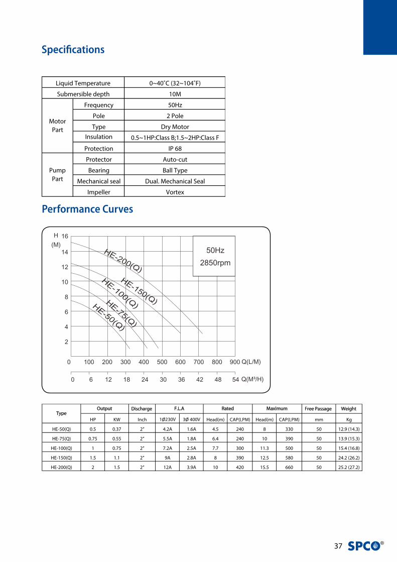
HE-50(Q) 0.5 0.37 2” 4.2A 1.6A 4.5 240 8 330 50 12.9 (14.3)
HE-75(Q) 0.75 0.55 2” 5.5A 1.8A 6.4 240 10 390 50 13.9 (15.3)
HE-100(Q) 1 0.75 2” 7.2A 2.5A 7.7 300 11.3 500 50 15.4 (16.8)
HE-150(Q) 1.5 1.1 2” 9A 2.8A 8 390 12.5 580 50 24.2 (26.2)
HE-200(Q) 2 1.5 2” 12A 3.9A 10 420 15.5 660 50 25.2 (27.2)
Output Rated MaximumF.L.AType
0~40˚C (32~104˚F)
10M
Frequency 50Hz
Pole 2 Pole
Type Dry Motor
Insulation 0.5~1HP:Class B;1.5~2HP:Class F
Protection IP 68
Protector Auto-cut
Bearing Ball Type
Mechanical seal Dual. Mechanical Seal
Impeller Vortex
Pump
Part
Liquid Temperature
Submersible depth
Motor
Part

HE
Seri
es -
50H
z
��
Materials
1
3
6
15-1
7
12
910
2
4
5
15-2
11
8
Thermal protector for 1 phase
Overload protector for 3 phase
EKK Eagle Burgmann Double mechanical seal
Pump volute2” solid free-passage
Cable gland sysWater tight cable gland with Epoxy Potting
Oil SealExtra protection for the leakage
1
3
6
15-1
7
12
910
2
4
5
15-2
11
8
Thermal protector for 1 phase
Overload protector for 3 phase
EKK Eagle Burgmann Double mechanical seal
Pump volute2” solid free-passage
Cable gland sysWater tight cable gland with Epoxy Potting
Oil SealExtra protection for the leakage
Sectional view
No Part Material
1 Cable H07RN-F/STOW/SJTOW
2 Handle Nylon6
3 Motor Cover PA66+30GF (0.5~1HP)
EN-GJL-200 (1.5~2HP)
4 Bracket EN-GJL-200
5 Motor Housing AISI 304
6 Shaft with Rotor AISI 410
7 Oil Chamber EN-GJL-200
8 Double Mech.Seal Upper : CA / CE
Lower : SIC / SIC
9 Seal Housing EN-GJL-200
10 Oil Seal NBR
11 Impeller EN-GJL-200
12 Pump Casing EN-GJL-200
15-1 Upper Bearing NTN/TPI
15-2 Lower Bearing NTN/TPI

�� ®
Dimensions
Type A A1 A2 B B1 B2 C C1 C2 D D1 D2 H H1 H2 H3 N N1 N2 N3
HE-50(Q) 244 82 118 231 81 150 165 82.5 82.5 164 80 84 466 336 151 141 470 342 161 90
HE-75(Q) 244 82 118 231 81 150 165 82.5 82.5 164 80 84 482 352 151 141 486 358 161 90
HE-100(Q) 244 82 118 231 81 150 165 82.5 82.5 164 80 84 496 366 151 141 500 372 161 90
HE-150(Q) 271 93 135 243 93 150 165 82.5 82.5 186 88 98 506 376 151 143 510 373 158 90
HE-200(Q) 271 93 135 243 93 150 165 82.5 82.5 186 88 98 520 396 151 143 530 393 158 90
Dimensions (mm)
N
N1
N2N3 B1 B2
B
C1
C2
C
H3
H
H2
H1
A
D
A2A1D
2D
1
173
0.5HP~1HP: 445.11.5~2HP: 468
128
142
43
250
135
0.5HP~1HP: 363.21.5~2HP: 383
94
142
166
79 1515
80.5
5.2
20.5
116
34
0.5HP~1HP: 451.5~2HP: 35
94
34.9125
HE-50~200
HE-50Q~100Q HE-50Q~200Q with QH coupling foot
» HE series standard version features a vertical, threaded outlet pump body.
» (Q) in the name-coding identifies the pump with horizontal flanged outlet.
» QH coupling foot is suitable for all HE pump with horiztontal volute.
» All single-phase pumps can be equipped with float switch upon request.

HE
Seri
es -
50H
z
�0
HE DN Series •SOLID FULL-PASSAGE SEWAGE PUMP
• For heavy-duty applications with soiled biological
wastewaters, sewage, rainwater
• For both domestic and professional use
• Recessed vortex impeller
• 2.5”& 3” (65mm&76mm) solid free-passage
• EKK Eagle Burgmann double mechanical seal in Si.Ca
• Stainless steel motor housing
Applications
Feature
• Viscosity of treated fluid : 1 mm²/s
• Density of treated fluid : 1 kg/dm3
• Max starts per hour : 20
Operating Limits
Vortex Impeller
1
3
6
15-1
9
12
7
10
2
45
15-2
11
8
Thermal protector for 1 phase
Overload protector for 3 phase
EKK Eagle Burgmann Double mechanical seal
Pump volute2.5” & 3” solid free-passage
Cable gland sysWater tight cable gland with Epoxy Potting
Long Life - Bearing
Oil SealExtra protection for the leakage
HE-200 DN65
HE-150 DN80 with QD-80
HE-300 DN80
Sectional view
�1 ®
Performance Curves
Discharge Free Passage QDC
HP KW Inch 1Ø230V 3Ø 400V Head(m) CAP(LPM) Head(m) CAP(LPM) mm 1ØKg 3Ø Kg
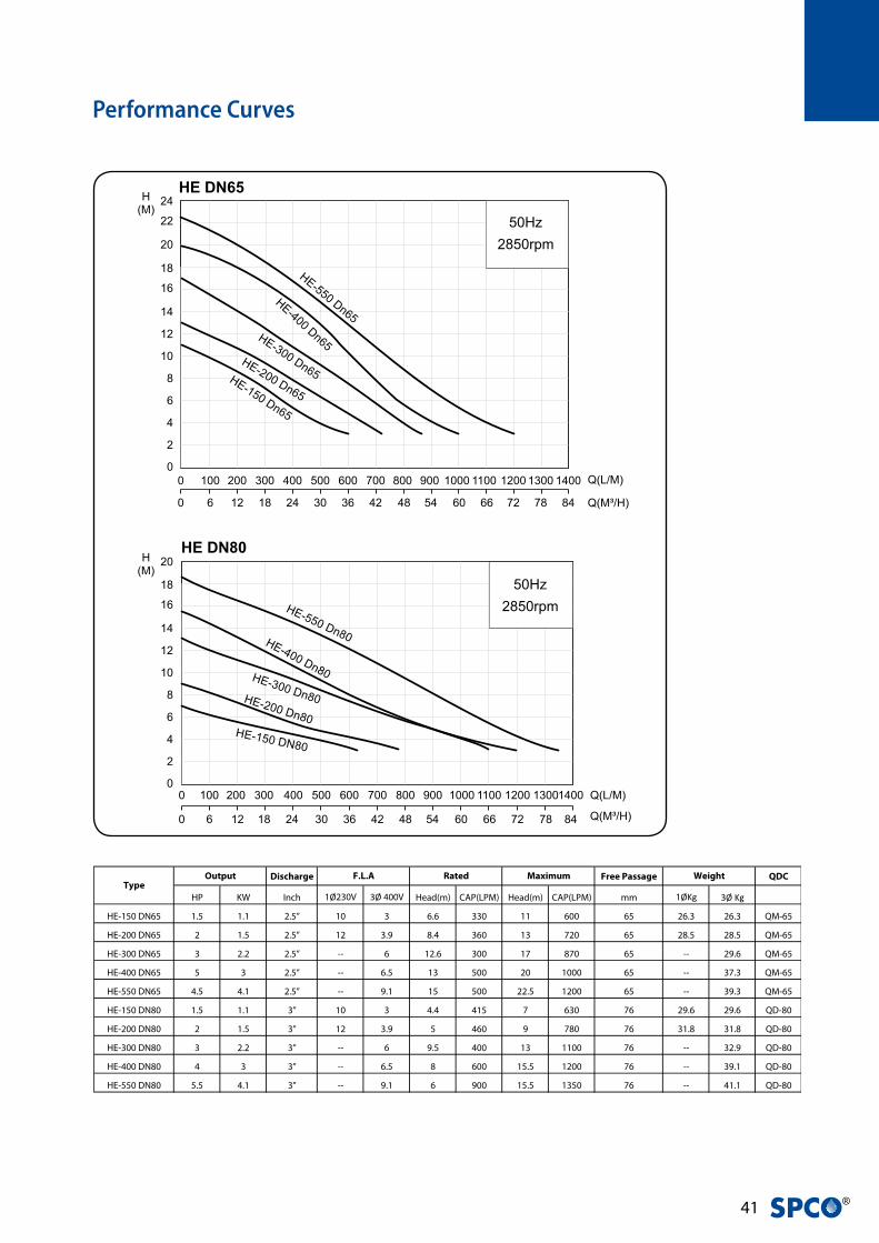
HE-150 DN65 1.5 1.1 2.5” 10 3 6.6 330 11 600 65 26.3 26.3 QM-65
HE-200 DN65 2 1.5 2.5” 12 3.9 8.4 360 13 720 65 28.5 28.5 QM-65
HE-300 DN65 3 2.2 2.5” -- 6 12.6 300 17 870 65 -- 29.6 QM-65
HE-400 DN65 5 3 2.5” -- 6.5 13 500 20 1000 65 -- 37.3 QM-65
HE-550 DN65 4.5 4.1 2.5” -- 9.1 15 500 22.5 1200 65 -- 39.3 QM-65
HE-150 DN80 1.5 1.1 3” 10 3 4.4 415 7 630 76 29.6 29.6 QD-80
HE-200 DN80 2 1.5 3” 12 3.9 5 460 9 780 76 31.8 31.8 QD-80
HE-300 DN80 3 2.2 3” -- 6 9.5 400 13 1100 76 -- 32.9 QD-80
HE-400 DN80 4 3 3” -- 6.5 8 600 15.5 1200 76 -- 39.1 QD-80
HE-550 DN80 5.5 4.1 3” -- 9.1 6 900 15.5 1350 76 -- 41.1 QD-80
TypeWeightOutput Rated MaximumF.L.A

HE
Seri
es -
50H
z
�2
Materials
No Part Material
1 Cable H07RN-F/SJTOW/STOW
2 Handle ASTM A36
3 Motor Cover EN-GJL-200
4 Bracket EN-GJL-200
5 Motor Housing AISI304
6 Shaft with Rotor AISI410
7 Oil Chamber EN-GJL-200
8 Double Mech.Seal Upper : CA / CE
Lower : SIC / SIC
9 Seal Housing EN-GJL-200
10 Oil Seal NBR
11 Impeller EN-GJL-200
12 Pump Casing EN-GJL-200
15-1 Upper Bearing NTN/TPI
15-2 Lower Bearing NTN/TPI
Vortex Impeller
1
3
6
15-1
9
12
7
10
2
45
15-2
11
8
Thermal protector for 1 phase
Overload protector for 3 phase
EKK Eagle Burgmann Double mechanical seal
Pump volute2.5” & 3” solid free-passage
Cable gland sysWater tight cable gland with Epoxy Potting
Long Life - Bearing
Oil SealExtra protection for the leakage
HE-200 DN65
HE-150 DN80 with QD-80
HE-300 DN80
Specifications
Note: Single lower bearing for 1.5HP/2HP; Double lower bearings for 3HP
0~40˚C (32~104˚F)
10M
Frequency 50Hz
Pole 2 Pole
Type Dry Motor
Insulation Class F
Protection IP 68
Protector Auto-cut
Bearing Ball Type
Mechanical seal Dual. Mechanical Seal
Impeller Vortex
Pump
Part
Liquid Temperature
Submersible depth
Motor
Part
�� ®
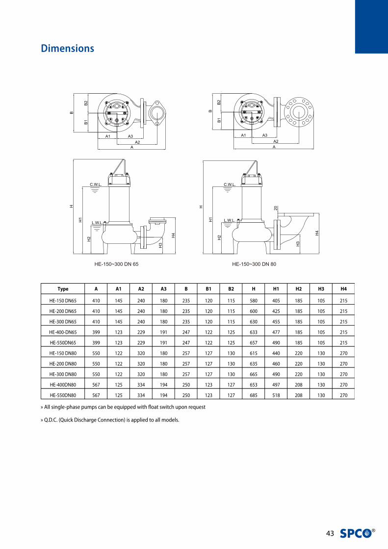
Type A A1 A2 A3 B B1 B2 H H1 H2 H3 H4
HE-150 DN65 410 145 240 180 235 120 115 580 405 185 105 215
HE-200 DN65 410 145 240 180 235 120 115 600 425 185 105 215
HE-300 DN65 410 145 240 180 235 120 115 630 455 185 105 215
HE-400-DN65 399 123 229 191 247 122 125 633 477 185 105 215
HE-550DN65 399 123 229 191 247 122 125 657 490 185 105 215
HE-150 DN80 550 122 320 180 257 127 130 615 440 220 130 270
HE-200 DN80 550 122 320 180 257 127 130 635 460 220 130 270
HE-300 DN80 550 122 320 180 257 127 130 665 490 220 130 270
HE-400DN80 567 125 334 194 250 123 127 653 497 208 130 270
HE-550DN80 567 125 334 194 250 123 127 685 518 208 130 270
Dimensions
H
H2
H1
H4
C.W.L.
L.W.L.
H3
A1A2
B2
B1
A
B
A3
H
H2
H1
C.W.L.
L.W.L.
H4
H3
20
B2
B1
B
A1
A
A3A2
HE-150~300 DN 65 HE-150~300 DN 80
» All single-phase pumps can be equipped with float switch upon request
» Q.D.C. (Quick Discharge Connection) is applied to all models.

EDW
Ser
ies
- 50
Hz
��
EDW Series •Submersible Dewatering pumps
• Agriculture industry: irrigation and underground water
• Aquaculture industry: drainage and water supply of fresh water
• Extraction of water from rivers, lakes and reservoirs.
• Landscape use and horticulture irrigation related operation.
• Circumferential cooling ensuring long life operation with high
efficiency
• Dry motor design with thermal auto-cut with water-cut cable –
• Good protection of motor from over-heating and water invasion
through cable
• Ni Chrome Steel impeller for abrasive liquids
• It can be used on land by replacing the strainer and base plate with a
check valve.
• Double Mechanical seal and oil seal to ensure long life operation
Applications
Feature
www.evak-pumps.com
EDW
CHROMIUM NICKEL MATERIALGOOD AGAINST CORROSION
HIGH EFFICIENCY CLOSED TYPE IMPELLER
OPTIONAL-SACRIFICIAL ANODEPEDW-SA-M10
FLANGE3”, 4”
PEDW-FL
ADAPTER FLANGE3”, 4”
PEDW-ADF
CHECK VALVE3”, 4”
PEDW-CKV
FLANGE KITS3”, 4”
PEDW-FLK
www.evak-pumps.com
EDW
CHROMIUM NICKEL MATERIALGOOD AGAINST CORROSION
HIGH EFFICIENCY CLOSED TYPE IMPELLER
OPTIONAL-SACRIFICIAL ANODEPEDW-SA-M10
FLANGE3”, 4”
PEDW-FL
ADAPTER FLANGE3”, 4”
PEDW-ADF
CHECK VALVE3”, 4”
PEDW-CKV
FLANGE KITS3”, 4”
PEDW-FLK
Optional Accessories

�� ®
Performance Curves
Specifications
Discharge Free Passage
HP KW Inch 1Ø230V 3Ø 400V Head(m) CAP(LPM) Head(m) CAP(LPM) mm 1Ø(Kg) 3Ø(Kg)
80EDW-5.20 2 1.5 3” 11 3.8 9.5 500 16.4 820 10 45.2 44.2
80EDW-5.30 3 2.2 3” 15 5.7 14.5 500 26.5 980 10 46.6 45.6
100EDW-5.30 3 2.2 4” 15 5.7 9.5 800 17 1200 10 46.6 45.6
80EDW-5.50 5 3.7 3” - 7.9 21.5 400 32.4 1040 10 - 48.2
100EDW-5.50 5 3.7 4” - 7.9 12.5 1000 22 1680 10 - 48.2
WeightOutput Rated MaximumF.L.AType
0~40˚C (32~104˚F)
10M
Frequency 50Hz
Pole 2 Pole
Type Dry Motor
Insulation Class F
Protection IP 68
Protector Auto-cut
Bearing Ball Type
Mechanical seal Dual. Mechanical Seal
Impeller Closed Type
Pump
Part
Liquid Temperature
Submersible depth
Motor
Part

EDW
Ser
ies
- 50
Hz
��
Materials
No Part Material
1 Motor Housing EN-GJL-200
2 Stator
3&4 Shaft with Rotor SUS 304
5 Motor Cover EN-GJL-200
6 Pump Casing EN-GJL-200
7 Mech. Seal Upper: CA/CE
(EKK Burgmann) Lower: SIC/SIC
13-1 Upper Bearing NTN/TPI
13-2 Lower Bearing NTN/TPI
14 Bottom Bearing Bracket EN-GJL-200
16 Shaft Sleeve SUS 304
17 Impeller Ni Chrome Steel
18 Inlet Plate EN-GJL-200
20 Upper Cover EN-GJL-200
28 Discharge EN-GJL-200
29 Flange EN-GJL-200
30 Strainer SUS 304
31 Base Plate EN-GJL-200
32 Outer Case SUS 304
33 Handle SC+PVC
34 Bracket EN-GJL-200
35&36 Centrifugal Switch
37 Centrifugal Switch Cover STEEL
39 Capacitor
40 Klixon Thermal Protector
Dimensions
Type A A1 A2 H H1 F G
80EDW-5.20S 247 160 235 568 209 125 14.5
80EDW-5.20T 247 160 235 523 187 125 14.5
80EDW-5.30S 260 185 235 568 209 150 14.5
80EDW-5.30T 260 185 235 523 187 150 14.5
100EDW-5.30S 260 185 235 568 209 150 14.5
100EDW-5.30T 260 185 235 523 187 150 14.5
80EDW-5.50T 260 185 235 548 187 150 14.5
100EDW-5.50T 260 185 235 548 187 150 14.5
L.W.L
A
A1 A2
H
H1
F G
» S: Single Phase ; T: Three Phase

�� ®
MAM Series •Heavy Duty Submersible Pumps
• Non-clog single channel impeller
• Robust construction
• Large solid passage
• Dry Tip (optional)
• Sewage
• Waste water
Applications
Feature
Specifications
0~40°C (32~104°F)
8M
Frequency 50Hz
Pole 4 Pole
Type Air-filled watertight
Insulation Class F
Protection IP 68
Bearing Ball Bearing
Mechanical seal Dual. Mechanical Seal
Impeller Single Channel, Non-Clog
Pump
Part
Liquid Temperature
Submersible depth
Motor
Part
Protector
Built-in overload protector(3HP)
Build-in thermal protector
(5-30HP)

MA
M S
erie
s -
50H
z
��
Performance Curves
Discharge Cable Free Passage Weight
HP KW Inch 1Ø230V 3Ø 400V Head(m) CAP(LPM) Head(m) CAP(LPM) M mm Kg
80MAM-5.30 3 2.2 3” - 5.2 11.2 200 4 1600 10 76 80
80MAM-5.50 5 3.7 3” - 8.4 15.8 200 9.1 1338 10 76 87
80MAM-5.75 7.5 5.5 3” - 12.6 19.3 300 12.8 1400 10 76 118
80MAM-5.100 10 7.5 3” - 16.9 22.6 300 16 1449 10 76 123
80MAM-5.150 15 11 3” - 23.8 28.5 300 22.7 1512 10 76 157
80MAM-5.200 20 15 3” - 31 34 300 28.4 1557 10 76 163
80MAM-5.300 30 22 3” - 42 39.5 300 34 1595 10 76 223
100MAM-5.50 5 3.7 4” - 8.4 9.1 1338 4 2407 10 76 89
100MAM-5.75 7.5 5.5 4” - 12.6 12.8 1400 9.3 2194 10 76 121
100MAM-5.100 10 7.5 4” - 16.9 16 1449 12.6 2270 10 76 125
100MAM-5.150 15 11 4” - 23.8 22.7 1512 18.3 2368 10 76 160
100MAM-5.200 20 15 4” - 31 28.4 1557 23.7 2440 10 76 166
100MAM-5.300 30 22 4” - 42 34 1595 28 2489 10 76 226
150MAM-5.75 7.5 5.5 6” - 12.6 9.3 2194 4 3379 10 76 127
150MAM-5.100 10 7.5 6” - 16.9 12.6 2270 4 3987 10 76 132
150MAM-5.150 15 11 6” - 23.8 18.3 2368 5.5 4472 10 76 166
150MAM-5.200 20 15 6” - 31 23.7 2440 8 5102 10 76 172
150MAM-5.300 30 22 6” - 42 28 2489 10 5566 10 76 232
Output Rated MaximumF.L.AType
Data Chart

�� ®
No Part Material
1 Submersible Cable
2 Lifting Hanger SS Steel
3 Thermal Protector
4 Ball Bearing
5 Impeller EN-GJL-200
6 Impeller Bolt AISI 304
7 Opposite Side Bracket EN-GJL-200
8 Rotor
9 Stator
10 Shaft AISI 403
11 Motor Frame EN-GJL-200
12 Power Side Bracket EN-GJL-200
13 Mechanical Seal Upper : CA/CE
Lower : SIC/SIC
14 Mechanical Seal Cover EN-GJL-200
15 Pump Casing EN-GJL-200
Materials
12
7
12
89
10
11
34
4
1314
515
6
Type A B C D E F H J L1
80MAM-5.30 534 320 378 157 285 298 668 210 279
80MAM-5.50 534 320 378 157 285 298 727 210 279
80MAM-5.75 640 381 453 188 360 334 824 255 310
80MAM-5.100 640 381 453 188 360 334 824 255 310
80MAM-5.150 734 455 513 221 420 350 938 315 329
80MAM-5.200 734 455 513 221 420 350 938 315 329
80MAM-5.300 777 497 533 245 440 363 1021 335 332
100MAM-5.50 577 320 420 157 315 313 727 210 279
100MAM-5.75 653 381 465 188 360 334 824 255 310
100MAM-5.100 653 381 465 188 360 334 824 255 310
100MAM-5.150 746 455 525 221 420 350 938 315 329
100MAM-5.200 746 455 525 221 420 350 938 315 329
100MAM-5.300 790 497 545 245 440 363 1021 335 332
150MAM-5.75 713 381 525 188 385 369 824 255 310
150MAM-5.100 713 381 525 188 385 369 824 255 310
150MAM-5.150 806 455 585 221 445 385 938 315 329
150MAM-5.200 806 455 585 221 445 385 938 315 329
150MAM-5.300 850 497 605 245 465 398 1021 335 332
Dimensions
MA
M S
erie
s -
50H
z
�0
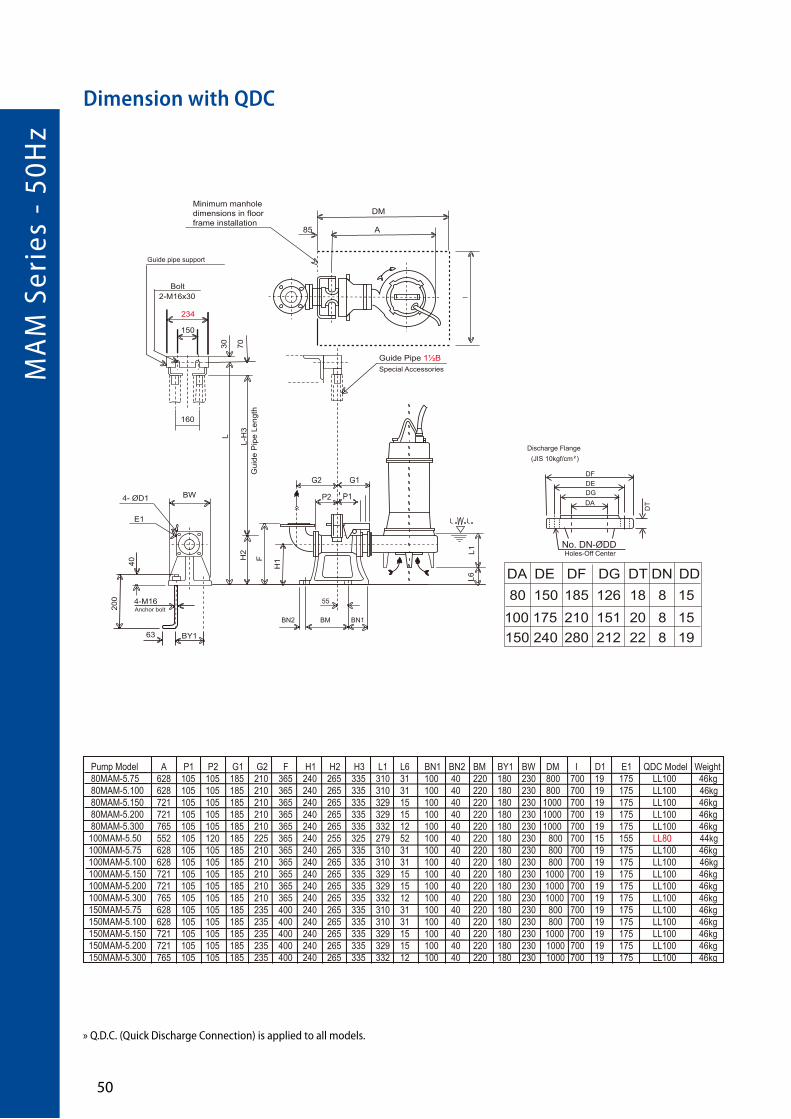
Dimension with QDC
L1
F
P2 P1
L6G2 G1
H1
No. DN-ØDDHoles-Off Center
DFDEDGDA
Discharge Flange(JIS 10kgf/cm )
DT
BN2 BM BN1
55
H2
L-H
3
L
7030
Guide pipe support
Bolt2-M16x30
234
150
160
Gui
de P
ipe
Leng
th
BW
E1
4- ØD1
200
40
BY163
4-M16Anchor bolt
Guide Pipe 1½BSpecial Accessories
Minimum manholedimensions in floorframe installation
DM
A85
DA DE DF DG DT DN DD80 150
100 175
A P1 P2 G1 G2 F H1 H2 H3 L1 L6 BN1 BN2 BM BY1 BW DM I D1 E1 QDC Model Weight628 105 105 185 210 365 240 265 335 310 31 100 40 220 180 230 800 700 19 175 LL100 46kg628 105 105 185 210 365 240 265 335 310 31 100 40 220 180 230 800 700 19 175 LL100 46kg721 105 105 185 210 365 240 265 335 329 15 100 40 220 180 230 1000 700 19 175 LL100 46kg721 105 105 185 210 365 240 265 335 329 15 100 40 220 180 230 1000 700 19 175 LL100 46kg765 105 105 185 210 365 240 265 335 332 12 100 40 220 180 230 1000 700 19 175 LL100 46kg552 105 120 185 225 365 240 255 325 279 52 100 40 220 180 230 800 700 15 155 LL80 44kg628 105 105 185 210 365 240 265 335 310 31 100 40 220 180 230 800 700 19 175 LL100 46kg628 105 105 185 210 365 240 265 335 310 31 100 40 220 180 230 800 700 19 175 LL100 46kg721 105 105 185 210 365 240 265 335 329 15 100 40 220 180 230 1000 700 19 175 LL100 46kg721 105 105 185 210 365 240 265 335 329 15 100 40 220 180 230 1000 700 19 175 LL100 46kg765 105 105 185 210 365 240 265 335 332 12 100 40 220 180 230 1000 700 19 175 LL100 46kg628 105 105 185 235 400 240 265 335 310 31 100 40 220 180 230 800 700 19 175 LL100 46kg628 105 105 185 235 400 240 265 335 310 31 100 40 220 180 230 800 700 19 175 LL100 46kg721 105 105 185 235 400 240 265 335 329 15 100 40 220 180 230 1000 700 19 175 LL100 46kg721 105 105 185 235 400 240 265 335 329 15 100 40 220 180 230 1000 700 19 175 LL100 46kg765 105 105 185 235 400 240 265 335 332 12 100 40 220 180 230 1000 700 19 175 LL100 46kg
150 240 280 212 22 8 198 158 15126 18
151 20210185
Pump Model 80MAM-5.75 80MAM-5.100 80MAM-5.150 80MAM-5.200 80MAM-5.300 100MAM-5.50 100MAM-5.75 100MAM-5.100 100MAM-5.150 100MAM-5.200 100MAM-5.300 150MAM-5.75 150MAM-5.100 150MAM-5.150 150MAM-5.200 150MAM-5.300
L1
F
P2 P1
L6
G2 G1
H1
No. DN-ØDDHoles-Off Center
DFDEDGDA
Discharge Flange(JIS 10kgf/cm )
DT
BN2 BM BN1
55
H2
L-H
3
L
7030
Guide pipe support
Bolt2-M16x30
234
150
160
Gui
de P
ipe
Leng
th
BW
E1
4- ØD1
200
40
BY163
4-M16Anchor bolt
Guide Pipe 1½BSpecial Accessories
Minimum manholedimensions in floorframe installation
DM
A85
DA DE DF DG DT DN DD80 150
100 175
A P1 P2 G1 G2 F H1 H2 H3 L1 L6 BN1 BN2 BM BY1 BW DM I D1 E1 QDC Model Weight628 105 105 185 210 365 240 265 335 310 31 100 40 220 180 230 800 700 19 175 LL100 46kg628 105 105 185 210 365 240 265 335 310 31 100 40 220 180 230 800 700 19 175 LL100 46kg721 105 105 185 210 365 240 265 335 329 15 100 40 220 180 230 1000 700 19 175 LL100 46kg721 105 105 185 210 365 240 265 335 329 15 100 40 220 180 230 1000 700 19 175 LL100 46kg765 105 105 185 210 365 240 265 335 332 12 100 40 220 180 230 1000 700 19 175 LL100 46kg552 105 120 185 225 365 240 255 325 279 52 100 40 220 180 230 800 700 15 155 LL80 44kg628 105 105 185 210 365 240 265 335 310 31 100 40 220 180 230 800 700 19 175 LL100 46kg628 105 105 185 210 365 240 265 335 310 31 100 40 220 180 230 800 700 19 175 LL100 46kg721 105 105 185 210 365 240 265 335 329 15 100 40 220 180 230 1000 700 19 175 LL100 46kg721 105 105 185 210 365 240 265 335 329 15 100 40 220 180 230 1000 700 19 175 LL100 46kg765 105 105 185 210 365 240 265 335 332 12 100 40 220 180 230 1000 700 19 175 LL100 46kg628 105 105 185 235 400 240 265 335 310 31 100 40 220 180 230 800 700 19 175 LL100 46kg628 105 105 185 235 400 240 265 335 310 31 100 40 220 180 230 800 700 19 175 LL100 46kg721 105 105 185 235 400 240 265 335 329 15 100 40 220 180 230 1000 700 19 175 LL100 46kg721 105 105 185 235 400 240 265 335 329 15 100 40 220 180 230 1000 700 19 175 LL100 46kg765 105 105 185 235 400 240 265 335 332 12 100 40 220 180 230 1000 700 19 175 LL100 46kg
150 240 280 212 22 8 198 158 15126 18
151 20210185
Pump Model 80MAM-5.75 80MAM-5.100 80MAM-5.150 80MAM-5.200 80MAM-5.300 100MAM-5.50 100MAM-5.75 100MAM-5.100 100MAM-5.150 100MAM-5.200 100MAM-5.300 150MAM-5.75 150MAM-5.100 150MAM-5.150 150MAM-5.200 150MAM-5.300
» Q.D.C. (Quick Discharge Connection) is applied to all models.

�1 ®
L1
F
P2 P1
L6
G2 G1
H1
No. DN-ØDDHoles-Off Center
DFDEDGDA
Discharge Flange(JIS 10kgf/cm ²)
DT
10 BN2 BN1
H2
L-H
3
L
5020
Guide pipe support
Bolt2-M12x30
128
60
70
Gui
de P
ipe
Leng
th
140
E1
4- ØD1
200
40
10063
2-M16Anchor bolt
Guide Pipe 1BSpecial Accessories
Minimum manholedimensions in floorframe installation
800
A56
DA DE DF DG DT DN DD
80 150 185 126 18 8 15
A P1 P2 G1 G2 F H1 H2 H3 L1 L6 BN1 BN2 D1 E1 QDC Model Weight492 75 90 125 165 285 175 230 280 279 7 75 90 15 155 LM80 17Kg492 75 90 125 165 285 175 230 280 279 7 75 90 15 155 LM80 17Kg
10
10
10
700
40
Pump Model80MAM-5.3080MAM-5.50
Dimension with QDC
» Q.D.C. (Quick Discharge Connection) is applied to all models.

MA
L Se
ries
- 5
0Hz
�2
MAL Series •Heavy Duty Submersible Pumps
• Semi-Open and non-clog Impeller
• Non-Clogging/Wide Rang
• Robust construction
• Superior heat Dissipation
• Built-in motor protection
• Sewage
• Strom water drainage
• Industrial Waste Water
Applications
Feature
Specifications
0~40°C (32~104°F)
8M
Frequency 50Hz
Pole 4 Pole
Type Air-filled watertight
Insulation Class F
Protection IP 68
Bearing Ball Bearing
Mechanical seal Dual. Mechanical Seal
Impeller Non-Clog
Built-in overload protector(up to 10HP)
Build-in thermal protector(15-60HP)
Leakage detector(40-60HP)2-30HP optional
Liquid Temperature
Submersible depth
Motor
Part
Pump
Part
Protector

�� ®
Performance Curves
Discharge Cable Free Passage Weight
HP KW Inch 1Ø230V 3Ø 400V Head(m) CAP(LPM) Head(m) CAP(LPM) M mm Kg
65MAL-5.20 2 1.5 2.5” - 3.9 15.5 70 9.9 450 10 40 52
80MAL-5.20 2 1.5 3” - 3.9 12.2 200 3.3 950 10 50 55
80MAL-5.30 3 2.2 3” - 5.2 15.8 100 4 1200 10 50 67
80MAL-5.50 5 3.7 3” - 8.3 19.1 100 10.4 1200 10 46 75
80MALC-5.75 7.5 5.5 3” - 11.3 22 200 12.3 1600 10 46 134
80MALC-5.100 10 7.5 3” - 15.5 27.3 200 15.3 1800 10 46 148
100MAL-5.50 5 3.7 4” - 8.3 14 500 5 1900 10 57 79
100MALC-5.75 7.5 5.5 4” - 11.3 22 200 12.3 1600 10 46 134
100MALC-5.100 10 7.5 4” - 15.5 27.3 200 15.3 1800 10 46 148
100MALB-5.75 7.5 5.5 4” - 11.3 16.1 500 8.3 2290 10 57 123
100MALB-5.100 10 7.5 4” - 15.5 20.8 500 11.5 2300 10 57 141
100MAL-5.150 15 11 4” - 21.5 28.4 500 16 2500 10 57 180
100MAL-5.200 20 15 4” - 28.5 33 500 20.6 2600 10 57 230
100MAL-5.250 25 18.5 4” - 35 39 500 24 2600 10 57 285
150MAL-5.75 7.5 5.5 6” - 11.3 11.2 1500 5.8 3050 10 68 146
150MAL-5.100 10 7.5 6” - 15.5 15.2 1500 8.3 3300 10 68 158
150MAL-5.150 15 11 6” - 21.5 20 1500 11.5 3600 10 68 199
150MAL-5.200 20 15 6” - 28.5 25.8 1500 15.2 3700 10 68 237
150MAL-5.250 25 18.5 6” - 35 28.3 1500 18 3800 10 68 300
150MAL-5.300 30 22 6” - 42 33 1500 20.5 4000 10 68 325
150MAL-5.400 40 30 6” - 58 35 1500 27.4 4000 10 68 355
150MAL-5.500 50 37 6” - 72.5 38.6 1500 30.4 4100 10 68 418
150MAL-5.600 60 45 6” - 87.5 44 1000 34.8 4300 10 68 456
200MAL-5.75 7.5 5.5 8” - 11.3 6.5 2600 4 3800 10 73 160
200MAL-5.100 10 7.5 8” - 15.5 9.6 2900 5.8 4700 10 73 176
200MAL-5.150 15 11 8” - 21.5 13.2 3100 9 5000 10 73 212
200MAL-5.200 20 15 8” - 28.5 17 3400 12 5300 10 73 260
200MAL-5.250 25 18.5 8” - 35 19.4 3500 13.5 5300 10 73 305
200MAL-5.300 30 22 8” - 42 23.2 3500 15 5500 10 73 330
200MAL-5.400 40 30 8” - 58 27.4 4000 20.5 6200 10 73 355
Output Rated MaximumF.L.AType
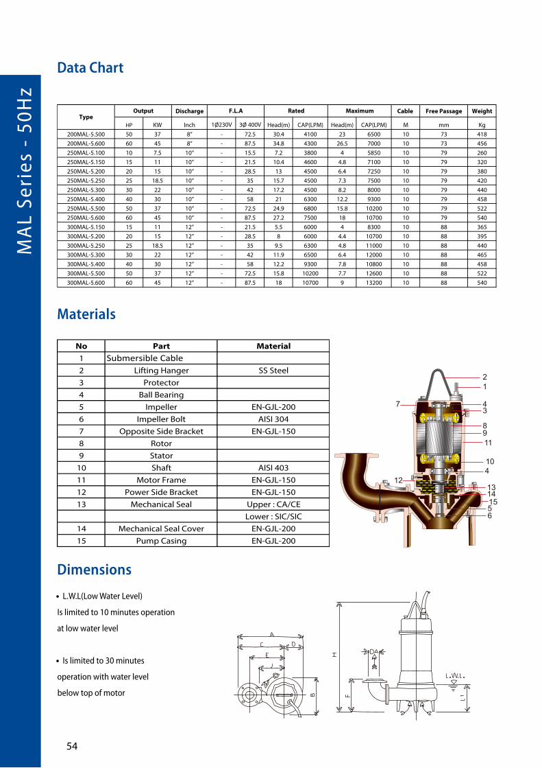
Data Chart
MA
L Se
ries
- 5
0Hz
��
Discharge Cable Free Passage Weight
HP KW Inch 1Ø230V 3Ø 400V Head(m) CAP(LPM) Head(m) CAP(LPM) M mm Kg
200MAL-5.500 50 37 8” - 72.5 30.4 4100 23 6500 10 73 418
200MAL-5.600 60 45 8” - 87.5 34.8 4300 26.5 7000 10 73 456
250MAL-5.100 10 7.5 10” - 15.5 7.2 3800 4 5850 10 79 260
250MAL-5.150 15 11 10” - 21.5 10.4 4600 4.8 7100 10 79 320
250MAL-5.200 20 15 10” - 28.5 13 4500 6.4 7250 10 79 380
250MAL-5.250 25 18.5 10” - 35 15.7 4500 7.3 7500 10 79 420
250MAL-5.300 30 22 10” - 42 17.2 4500 8.2 8000 10 79 440
250MAL-5.400 40 30 10” - 58 21 6300 12.2 9300 10 79 458
250MAL-5.500 50 37 10” - 72.5 24.9 6800 15.8 10200 10 79 522
250MAL-5.600 60 45 10” - 87.5 27.2 7500 18 10700 10 79 540
300MAL-5.150 15 11 12” - 21.5 5.5 6000 4 8300 10 88 365
300MAL-5.200 20 15 12” - 28.5 8 6000 4.4 10700 10 88 395
300MAL-5.250 25 18.5 12” - 35 9.5 6300 4.8 11000 10 88 440
300MAL-5.300 30 22 12” - 42 11.9 6500 6.4 12000 10 88 465
300MAL-5.400 40 30 12” - 58 12.2 9300 7.8 10800 10 88 458
300MAL-5.500 50 37 12” - 72.5 15.8 10200 7.7 12600 10 88 522
300MAL-5.600 60 45 12” - 87.5 18 10700 9 13200 10 88 540
TypeOutput F.L.A Rated Maximum
Materials
No Part Material
1 Submersible Cable2 Lifting Hanger SS Steel
3 Protector
4 Ball Bearing
5 Impeller EN-GJL-200
6 Impeller Bolt AISI 304
7 Opposite Side Bracket EN-GJL-150
8 Rotor
9 Stator
10 Shaft AISI 403
11 Motor Frame EN-GJL-150
12 Power Side Bracket EN-GJL-150
13 Mechanical Seal Upper : CA/CE
Lower : SIC/SIC
14 Mechanical Seal Cover EN-GJL-200
15 Pump Casing EN-GJL-200
12
7
12
89
10
11
34
4
1314
515
6
Dimensions
• L.W.L(Low Water Level)
Is limited to 10 minutes operation
at low water level
• Is limited to 30 minutes
operation with water level
below top of motor
Data Chart

�� ®
Dimensions
Type A B C D E F H J L1
65MAL-5.20 497 291 353 144 265 200 576 200 140
80MAL-5.20 524 292 378 146 285 220 597 210 165
80MAL-5.30 542 308 388 154 295 220 654 220 165
80MAL-5.50 567 328 403 164 310 220 687 235 165
80MALC-5.75 618 379 428 190 335 307 753 260 205
80MALC-5.100 648 399 448 200 355 305 751 280 205
100MAL-5.50 614 335 445 169 340 250 706 235 185
100MALC-5.75 660 379 470 190 365 322 753 260 205
100MALC-5.100 690 399 490 200 385 320 751 280 205
100MALB-5.75 646 369 460 186 355 323 768 250 205
100MALB-5.100 673 385 480 193 375 323 760 270 205
100MAL-5.150 701 402 500 201 395 323 859 290 205
100MAL-5.200 741 441 520 221 415 330 954 310 205
100MAL-5.250 741 441 520 221 415 330 958 310 205
150MAL-5.75 750 398 550 200 410 381 799 280 245
150MAL-5.100 780 418 570 210 430 377 784 300 245
150MAL-5.150 810 438 590 220 450 377 883 320 245
150MAL-5.200 810 438 590 220 450 377 972 320 245
150MAL-5.250 848 476 610 238 470 381 979 340 245
150MAL-5.300 848 476 610 238 470 381 979 340 245
150MAL-5.400 912 520 650 262 510 468 1284 360 1080
150MAL-5.500 912 520 650 262 510 468 1434 360 1165
150MAL-5.600 912 520 650 262 510 468 1434 360 1165
200MAL-5.75 832 430 615 217 450 414 826 300 285
200MAL-5.100 863 453 635 228 470 410 809 320 285
200MAL-5.150 863 453 635 228 470 410 908 320 285
200MAL-5.200 896 479 655 241 490 411 995 340 285
200MAL-5.250 932 512 675 257 510 415 1001 360 285
200MAL-5.300 932 512 675 257 510 415 1001 360 285
200MAL-5.400 937 520 675 262 510 483 1284 360 1080
200MAL-5.500 937 520 675 262 510 483 1434 360 1165
200MAL-5.600 937 520 675 262 510 483 1434 360 1165
250MAL-5.100 969 525 700 269 500 622 904 370 400
250MAL-5.150 993 541 720 273 520 634 1000 390 400
250MAL-5.200 1007 549 730 277 530 646 1086 400 400
250MAL-5.250 1007 549 730 277 530 646 1089 400 400
250MAL-5.300 1007 549 730 277 530 646 1089 400 400
250MAL-5.400 1125 660 790 335 590 706 1336 460 1132
250MAL-5.500 1125 660 790 335 590 706 1505 460 1236
250MAL-5.600 1125 660 790 335 590 706 1505 460 1236
300MAL-5.150 1100 588 798 302 575 671 1050 420 450
300MAL-5.200 1100 588 798 302 575 671 1131 420 450
300MAL-5.250 1135 618 818 317 595 668 1131 440 450
300MAL-5.300 1135 618 818 317 595 668 1131 440 450
300MAL-5.400 1172 660 838 335 615 726 1336 460 1132
300MAL-5.500 1172 660 838 335 615 726 1505 460 1236
300MAL-5.600 1172 660 838 335 615 726 1505 460 1236
» Q.D.C. (Quick Discharge Connection) is applied to all models.

MA
L Se
ries
- 5
0Hz
��
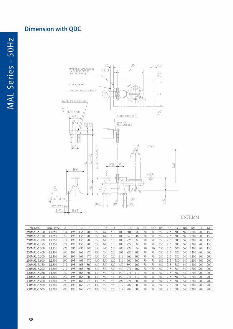
Dimension with QDC
Minimum manholedimensions in �oorframe installation
Special Accessories
1½B
UNIT:MM
Model QDC Type A P1 P2 G1 G2 F H1 H2 H3 L1 L2 L6 BN1 BN2 BM BY1 BW DM I D1 E1 KG
80MALC-5.75 LL80 635 105 120 185 195 350 240 255 325 205 653 43 100 40 220 180 230 800 700 15 155 44
80MALC-5.100 LL80 665 105 120 185 195 350 240 255 325 205 651 45 100 40 220 180 230 800 700 15 155 44
100MAL-5.50 LL100 589 105 105 185 210 365 240 265 335 185 606 115 100 40 220 180 230 800 700 19 175 46
100MALC-5.75 LL80 635 105 120 185 225 365 240 255 325 205 653 43 100 40 220 180 230 800 700 15 155 44
100MALC-5.100 LL80 665 105 120 185 225 365 240 255 325 205 651 45 100 40 220 180 230 800 700 15 155 44
100MALB-5.75 LL100 621 105 105 185 210 365 240 265 335 205 668 42 100 40 220 180 230 800 700 19 175 46
100MALB-5.100 LL100 648 105 105 185 210 365 240 265 335 205 660 42 100 40 220 180 230 800 700 19 175 46
100MAL-5.150 LL100 676 105 105 185 210 365 240 265 335 205 699 42 100 40 220 180 230 1000 700 19 175 46
100MAL-5.200 LL100 716 105 105 185 210 365 240 265 335 205 794 35 100 40 220 180 230 1000 700 19 175 46
100MAL-5.250 LL100 716 105 105 185 210 365 240 265 335 205 798 35 100 40 220 180 230 1000 700 19 175 46

�� ®
UNIT:MM
DA DE DF DG DT DN DD150 240200 290 12 23
8 19212 22262 26330
280
MODEL QDC Type A P1 P2 G F H1 H2 H3 L1 L2 L6 BN1 BN2 BM BP BY1 BW DM I D1 E1 KG
150MAL-5.75 LL125 635 155 195 325 450 290 362 432 245 699 69 60 60 370 165 280 330 1000 700 16 210 65
150MAL-5.100 LL125 665 155 195 325 450 290 362 432 245 684 73 60 60 370 165 280 330 1000 700 16 210 65
150MAL-5.150 LL125 695 155 195 325 450 290 362 432 245 723 73 60 60 370 165 280 330 1000 700 16 210 65
150MAL-5.200 LL125 695 155 195 325 450 290 362 432 245 812 73 60 60 370 165 280 330 1000 700 16 210 65
150MAL-5.250 LL125 733 155 195 325 450 290 362 432 245 819 69 60 60 370 165 280 330 1000 700 16 210 65
150MAL-5.300 LL125 733 155 195 325 450 290 362 432 245 819 69 60 60 370 165 280 330 1000 700 16 210 65
150MAL-5.400 LI150 777 155 205 355 480 320 405 475 288 884 210 60 60 390 170 300 350 1100 800 16 250 80
150MAL-5.500 LI150 777 155 205 355 480 320 405 475 296 939 210 60 60 390 170 300 350 1100 800 16 250 80
150MAL-5.600 LI150 777 155 205 355 480 320 405 475 296 939 210 60 60 390 170 300 350 1100 800 16 250 80
200MAL-5.75 LL150 672 155 205 355 495 320 405 475 285 726 81 60 60 390 170 300 350 1100 800 16 250 80
200MAL-5.100 LL150 703 155 205 355 495 320 405 475 285 709 85 60 60 390 170 300 350 1100 800 16 250 80
200MAL-5.150 LL150 703 155 205 355 495 320 405 475 285 748 85 60 60 390 170 300 350 1100 800 16 250 80
200MAL-5.200 LL150 736 155 205 355 495 320 405 475 285 835 84 60 60 390 170 300 350 1100 800 16 250 80
200MAL-5.250 LL150 772 155 205 355 495 320 405 475 285 841 80 60 60 390 170 300 350 1100 800 16 250 80
200MAL-5.300 LL150 772 155 205 355 495 320 405 475 285 841 80 60 60 390 170 300 350 1100 800 16 250 80
200MAL-5.400 LL150 777 155 205 355 495 320 405 475 288 884 210 60 60 390 170 300 350 1100 800 16 250 80
200MAL-5.500 LL150 777 155 205 355 495 320 405 475 296 939 210 60 60 390 170 300 350 1100 800 16 250 80
200MAL-5.600 LL150 777 155 205 355 495 320 405 475 296 939 210 60 60 390 170 300 350 1100 800 16 250 80
Dimension with QDC
MA
L Se
ries
- 5
0Hz
��
UNIT:MM
MODEL QDC Type A P1 P2 F H1 H2 H3 L1 L2 L6 BN1 BN2 BM BP BY1 BW DM I KG
250MAL-5.100 LL250 834 195 435 700 350 440 510 400 804 58 70 70 650 215 500 560 1200 900 150
250MAL-5.150 LL250 858 195 435 700 350 440 510 400 840 46 70 70 650 215 500 560 1200 900 150
250MAL-5.200 LL250 872 195 435 700 350 440 510 400 926 34 70 70 650 215 500 560 1200 900 150
250MAL-5.250 LL250 872 195 435 700 350 440 510 400 929 34 70 70 650 215 500 560 1200 900 150
250MAL-5.300 LL250 872 195 435 700 350 440 510 400 929 34 70 70 650 215 500 560 1200 900 150
250MAL-5.400 LL300 990 195 465 970 430 550 620 292 886 300 70 70 680 215 580 640 1200 900 200
250MAL-5.500 LL300 990 195 465 970 430 550 620 319 960 300 70 70 680 215 580 640 1200 900 200
250MAL-5.600 LL300 990 195 465 970 430 550 620 319 960 300 70 70 680 215 580 640 1200 900 200
300MAL-5.150 LL300 917 195 465 800 430 550 620 450 890 109 70 70 680 215 580 640 1200 900 200
300MAL-5.200 LL300 917 195 465 800 430 550 620 450 971 109 70 70 680 215 580 640 1200 900 200
300MAL-5.250 LL300 952 195 465 800 430 550 620 450 971 112 70 70 680 215 580 640 1200 900 200
300MAL-5.300 LL300 952 195 465 800 430 550 620 450 971 112 70 70 680 215 580 640 1200 900 200
300MAL-5.400 LL300 990 195 465 970 430 550 620 292 921 300 70 70 680 215 580 640 1200 900 200
300MAL-5.500 LL300 990 195 465 970 430 550 620 319 989 300 70 70 680 215 580 640 1200 900 200
300MAL-5.600 LL300 990 195 465 970 430 550 620 319 989 300 70 70 680 215 580 640 1200 900 200
Dimension with QDC

�� ®
UNIT:MM
Model QDC Type A P1 P2 G1 G2 F H1 H2 H3 L1 L2 L6 BN1 BN2 D1 E1 KG
65MAL-5.20 LM65 464 75 95 120 160 250 145 190 240 140 476 50 75 95 12 140 14
80MAL-5.20 LM80 481 75 90 125 165 285 175 230 280 165 497 65 75 90 15 155 17
80MAL-5.30 LM80 499 75 90 125 165 285 175 230 280 165 554 65 75 90 15 155 17
80MAL-5.50 LM80 524 75 90 125 165 285 175 230 280 165 587 65 75 90 15 155 17
Dimension with QDC

MA
K S
erie
s -
50H
z
�0
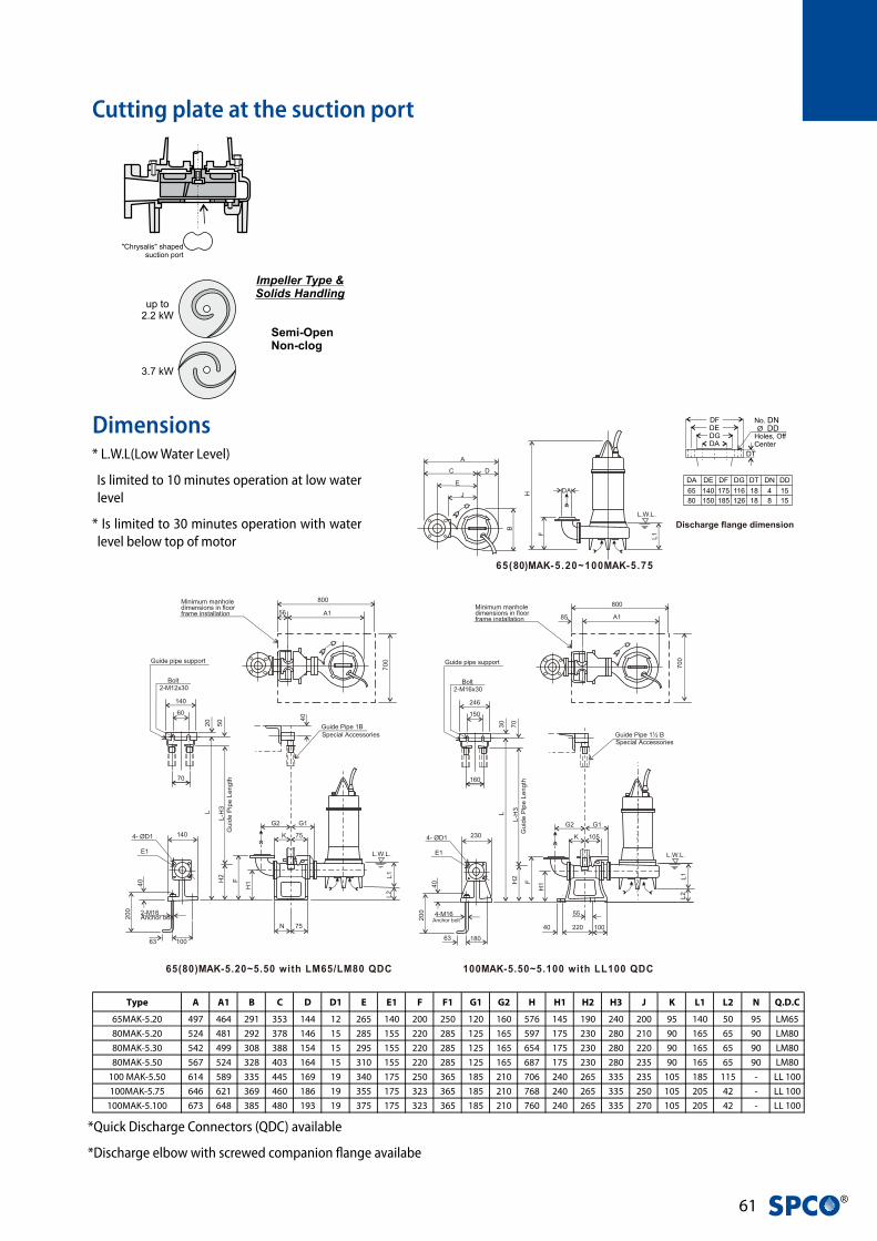
MAK Series •Submersible Pumps with cutter plate
• Non-clog operation with “cutting” action
• Robust construction
• Double mechanical seal in oil chamber
• In built motor protection
• Sewage
• Strom water drainage
• Industrial Waste Water
Applications
Feature
Discharge Free Passage Weight
HP KW Inch 1Ø230V 3Ø 400V Head(m) CAP(LPM) Head(m) CAP(LPM) mm Kg
65MAK-5.20 2 1.5 2.5” - 3.9 14 70 10 400 40 52 LM 65
80MAK-5.20 2 1.5 3” - 3.9 9.3 400 3 930 50 55 LM 80
80MAK-5.30 3 2.2 3” - 5.2 14.5 100 4 1150 50 67 LM 80
80MAK-5.50 5 3.7 3” - 8.3 18.4 100 10.4 1200 46 75 LM 80
100MAK-5.50 5 3.7 4” - 8.3 13.9 500 4 2000 57 79 LL 100
100MAK-5.75 7.5 5.5 4” - 11.3 16.1 500 8.5 2250 57 123 LL 100
100MAK-5.100 10 7.5 4” - 15.5 21.8 200 11.5 2300 57 141 LL 100
Type
Q.D.COutput Rated MaximumF.L.A
Performance curve
•Submersible pump with non-clog semi open impeller
•Maximum solids handling: refer to table
• Maximum submergence: 8 m
• Maximum liquid temperature: 40 °C
Specifications
�1 ®
Type A A1 B C D D1 E E1 F F1 G1 G2 H H1 H2 H3 J K L1 L2 N Q.D.C
65MAK-5.20 497 464 291 353 144 12 265 140 200 250 120 160 576 145 190 240 200 95 140 50 95 LM65
80MAK-5.20 524 481 292 378 146 15 285 155 220 285 125 165 597 175 230 280 210 90 165 65 90 LM80
80MAK-5.30 542 499 308 388 154 15 295 155 220 285 125 165 654 175 230 280 220 90 165 65 90 LM80
80MAK-5.50 567 524 328 403 164 15 310 155 220 285 125 165 687 175 230 280 235 90 165 65 90 LM80
100 MAK-5.50 614 589 335 445 169 19 340 175 250 365 185 210 706 240 265 335 235 105 185 115 - LL 100
100MAK-5.75 646 621 369 460 186 19 355 175 323 365 185 210 768 240 265 335 250 105 205 42 - LL 100
100MAK-5.100 673 648 385 480 193 19 375 175 323 365 185 210 760 240 265 335 270 105 205 42 - LL 100
SERIES 50HZECK
Submersible Sewage Pump with Cutter Plate
A
C D
E
J
B
DAH
F
L.W.L.
L1
L.W.L.
L1
800
56 A1
700
140
60
20 50
70
Minimum manholedimensions in floorframe installation
Bolt2-M12x30
Guide pipe support
40
K 75
G1G2
N 75
L2
2-M16Anchor bolt
4- ØD1
E1
140
40
200
H1FH
2
L
L-H
3G
uide
Pip
e Le
ngth
63 100
Guide Pipe 1BSpecial Accessories Guide Pipe 1½ B
Special Accessories
L.W.L.
L1L2
800
85 A1
700
246
150
30 70
160
Minimum manholedimensions in floorframe installation
Bolt2-M16x30
Guide pipe support
K 105
G1G2
40 100
4-M16Anchor bolt
4- ØD1
E1
230
40
200
H1FH
2
L
L-H
3G
uide
Pip
e Le
ngth
220
55
18063
65(80)MAK-5 .20~100MAK-5 .75
65(80)MAK-5.20~5.50 with LM65/LM80 QDC 100MAK-5.50~5.100 with LL100 QDC
* L.W.L(Low Water Level)
Is limited to 10 minutes operation at low water level
* Is limited to 30 minutes operation with water level below top of motor
Dimensions
*Quick Discharge Connectors (QDC) available
*Discharge elbow with screwed companion flange availabe
Cutting plate at the suction port
Discharge flange dimension

HS
Seri
es -
50H
z
�2
HS Series •Submersible Drainage Pumps
Performance Curves
Specifications
Applications
Emptying of septic tanks and residential sumps
0~50˚C
Frequency 50Hz
Pole 2 Pole
Type Dry Motor
Insulation Class F
Protection IP 68
Protection device Thermal Protector(Single phase)
Bearing Double shielded Ball Bearing
Mechanical seal Dual. Mechanical Seal
Impeller Open Impeller
0~35˚C
Frequency 50Hz
Pole 2 Pole
Type Dry Motor
Insulation Class F
Protection IP 68
Protection device Thermal Protector(Single phase)
Bearing Double shielded Ball Bearing
Mechanical seal Dual. Mechanical Seal
Impeller Vortex Impeller
Motor
Part
Pump
Part
Pump
Part
Liquid Temperature
Motor
Part
Liquid Temperature
Discharge Cable Free Passage
HP KW Inch Head(m) CAP(LPM) Head(m) CAP(LPM) M mm
HS-07 0.75 0.55 RP 1.5” 8.6 100 10.9 250 10 8
HS-10 1 0.75 RP 1.5” 11.2 100 14 325 10 8
HS-15 1.5 1.1 RP 1.5” 11.9 150 16.1 375 10 8
HS-20 2 1.5 RP 1.5” 15.6 150 20.6 420 10 8
Discharge Cable Free Passage
HP KW Inch Head(m) CAP(LPM) Head(m) CAP(LPM) M mm
HT-07 0.75 0.55 RP 1.5” 7.1 80 9.1 260 5 35
HT-10 1 0.75 RP 2” 7.1 100 7.7 400 10 50
HT-15 1.5 1.1 RP 2” 8.6 100 9.1 450 10 50
HT-20 2 1.5 RP 2” 10.2 150 11 550 10 50
TypeOutput Rated Maximum
Output Rated MaximumType
HS - 07
Power (HP)
Series name
Type Key

�� ®
Materials
Dimensions
Part Material
Cable H07RN-F
Handle AISI304+Nylon
Motor Cover AISI 304
Motor Casing AISI 304
Fixing Ring AISI 304
Pump Body AISI 304
Mechanical Seal Sic/Sic/NBR
Impeller AISI 304
Key AISI 304
Pump Casing AISI 304
Oil Seal NBR
Shaft AISI 304
V-type axial oil seal NBR
Suction Flange AISI 304
Single-Phase
Three-Phase
Type H H1 H2 L L1
HS-07 357 437 341 459 370
HS-10 407 497 391 514 425
HS-15 407 497 391 514 425
Type H H2 Weight
HS-07 357 341 12
HS-10 357 341 12
HS-15 407 391 15
HS-20 407 391 17
Type H H1 H2 L L1
HS-07 357 437 341 459 370
HS-10 407 497 391 514 425
HS-15 407 497 391 514 425
Type H H2 Weight
HS-07 357 341 12
HS-10 357 341 12
HS-15 407 391 15
HS-20 407 391 17

HS
Seri
es -
50H
z
��
HS -03 Submersible pump
Type Key
Applications
• Domestic drainage
• Grey water drainage.
• Koi pond
• Light waste water discharge.
• Hydro-sanitary
• Emergencies flooding pumping in homes
• Fountain and landscape
• Drainage pumping.
• Livestocks
Stainless Steel Series electric submersible pumps
Compact design with Top Discharge Outlet reduces space usage for installation in small manholes, for use in domestic, installations and small featured works.
Two different types of lever sensors:
• Mechanical activated float switch with cable extender (A)
• Vertical Mechanical activated Float Switch with case-ment (S)
Top discharged cools and removes heat from the motor through the outlet.
It allows these pumps to be used even when only par-tially submerged.
Every model undergoes hydrostatic testing for leakage from the casing and mechanical seals.
Features
Accessories
Minimum suction devices Impeller
With float switch and vertical level float switch
MaterialsNo Part Material
1 Cable H07RN-F
2 Float switch Plastic
3 Handle NY66+G30
4 Motor Cover AISI 304
5 Motor housing AISI 304
6 Oil seal NBR
7 Mechanical SealCarbon Graphite
Ceramic / NBR/ 304
8 Shaft AISI 410
9 Pump housing AISI 304
10 Impeller AISI 304
11 Pump casing AISI 304
12 Strainer AISI 304
13 Spring washer AISI 304
14 Hex domed nuts AISI 304
HS - 07 M A - 32
Discharge size A =Float switch S =Vertical level switch M = Single Phase T = Three Phase Power (HP) Series name
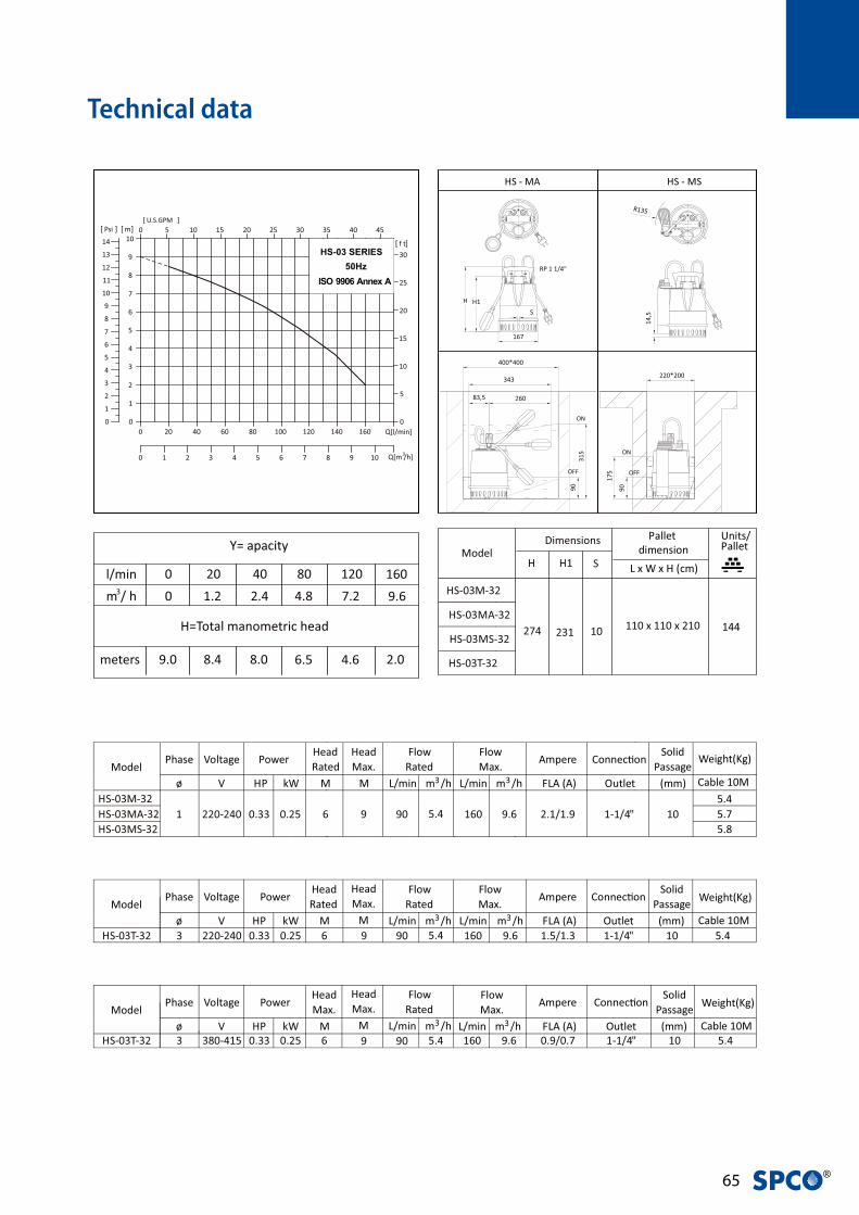
�� ®
Technical data

HT
Seri
es -
50H
z
��
Discharge Cable Free Passage
HP KW Inch Head(m) CAP(LPM) Head(m) CAP(LPM) M mm
HS-07 0.75 0.55 RP 1.5” 8.6 100 10.9 250 10 8
HS-10 1 0.75 RP 1.5” 11.2 100 14 325 10 8
HS-15 1.5 1.1 RP 1.5” 11.9 150 16.1 375 10 8
HS-20 2 1.5 RP 1.5” 15.6 150 20.6 420 10 8
Discharge Cable Free Passage
HP KW Inch Head(m) CAP(LPM) Head(m) CAP(LPM) M mm
HT-07 0.75 0.55 RP 1.5” 7.1 80 9.1 260 5 35
HT-10 1 0.75 RP 2” 7.1 100 7.7 400 10 50
HT-15 1.5 1.1 RP 2” 8.6 100 9.1 450 10 50
HT-20 2 1.5 RP 2” 10.2 150 11 550 10 50
TypeOutput Rated Maximum
Output Rated MaximumType
HT Series •Submersible Drainage Pumps
Specifications
Applications
Emptying of septic tanks and residential sumps
Performance Curves
0~50˚C
Frequency 50Hz
Pole 2 Pole
Type Dry Motor
Insulation Class F
Protection IP 68
Protection device Thermal Protector(Single phase)
Bearing Double shielded Ball Bearing
Mechanical seal Dual. Mechanical Seal
Impeller Open Impeller
0~35˚C
Frequency 50Hz
Pole 2 Pole
Type Dry Motor
Insulation Class F
Protection IP 68
Protection device Thermal Protector(Single phase)
Bearing Double shielded Ball Bearing
Mechanical seal Dual. Mechanical Seal
Impeller Vortex Impeller
Motor
Part
Pump
Part
Pump
Part
Liquid Temperature
Motor
Part
Liquid Temperature

�� ®
Type H H1 H2 H3 L1 C DNM Weight
HT-07 403 88 483 185 350 193 RP 1.5'' 11
HT-10 486 111.5 566 268 350 198 RP2'' 14
HT-15 486 111.5 566 268 350 198 RP2'' 15
Type H H1 C DNM Weight
HT-07 403 88 193 RP 1.5'' 11
HT-10 436 111.5 198 RP2'' 12
HT-15 486 111.5 198 RP2'' 14
HT-20 486 111.5 198 RP2'' 15
Single-Phase
Three-Phase
Materials
Dimensions
All technical information is subject to change without notice.
Part Material
Cable H07RN-F
Handle AISI304+Nylon
Motor Cover AISI 304
Motor Casing AISI 304
Fixing Ring AISI 304
Pump Body AISI 304
Mechanical Seal Sic/Sic/NBR
Impeller AISI 304
Key AISI 304
Pump Casing AISI 304
Oil Seal NBR
Shaft AISI 304
V-type axial oil seal NBR
Suction Flange AISI 304
Type H H1 H2 H3 L1 C DNM Weight
HT-07 403 88 483 185 350 193 RP 1.5'' 11
HT-10 486 111.5 566 268 350 198 RP2'' 14
HT-15 486 111.5 566 268 350 198 RP2'' 15
Type H H1 C DNM Weight
HT-07 403 88 193 RP 1.5'' 11
HT-10 436 111.5 198 RP2'' 12
HT-15 486 111.5 198 RP2'' 14
HT-20 486 111.5 198 RP2'' 15

NJ
Seri
es -
50H
z
��
Performance Curves
NJ Series •Submersible Jet Aerators
Applications• The wastewater treatment aeration and agitation
• High oxygen transfer rate
• BOD easy to remove from wastewater treatment
• Mixing and stirring applications for uniform MLSS
• Provide coarse/gross bubbles
Features
Specifications
www.evak-pumps.com
1
6
15-2
13
8
11
10
54
9
12
2
15-1
26
3
7
0~40˚C (32~104˚F)
10M
Frequency 50Hz
Pole 2 Pole
Type Dry Motor
Insulation 0.5~3HP:Class B; 5~7.5HP:Class F
Protection IP 68
Protector Auto-cut
Bearing Ball Type
Mechanical seal Dual. Mechanical Seal
Impeller Semi-Open
Pump
Part
Liquid Temperature
Submersible depth
Motor
Part

�� ®
Materials
Data chart
Discharge
HP KW Inch 1Ø230V 3Ø 400V AIR(m3/h) OTR(Kg-O2/H) HR(m) L(m) W(m) H(m) 1ØKg 3ØKg
80NJ-5.05 0.5 0.37 3” 4A 1.2A 5 0.12-0.23 1.5 2 1.8 2 21.7 21.4
80NJ-5.10 1 0.75 3” 5A 2.1A 10 0.3-0.5 2 3 2.5 3 26.5 26.2
80NJ-5.20 2 1.5 3” 11.8A 3.6A 22 0.9-1.1 2.5 4 3.5 3.5 37 36.3
80NJ-5.30 3 2.2 3” 15A 4.5A 40 1.9-2.2 3 5 4.5 4 41.1 37.4
80NJ-5.50 5 3.7 3” -- 8.2A 70 2.8-3.3 3.5 6 5 5 -- 51.2
80NJ-5.75 7.5 5.5 3” -- 11.5A 100 4.2-4.8 4 7 6 6 -- 57.2
WeightOutput F.L.AType
Rated Aeration Tank
Note: » Quick discharge connection( QM-80) Duck Foot is optional
No Part Material
1 Cable H07RN-F /SJTOW/STOW
2 Handle Nylon 6/ASTM A36
3 Motor Cover Nylon 66/EN-GJL-200
4 Bracket EN-GJL-200
5 Motor Housing + Stator AISI 304
6 Shaft with Rotor AISI 410
7 Oil Chamber EN-GJL-200
8 Double Mech.Seal Upper : CA / CE
Lower : SIC / SIC
9 Seal Housing EN-GJL-200
10 Oil Seal NBR
11 Impeller EN-GJL-200
12 Pump Casing EN-GJL-200
13 Protector KLIXON
26 Jet Aerator EN-GJL-200
15-1 Upper Bearing NTN/TPI
15-2 Lower Bearing NTN/TPI
www.evak-pumps.com
1
6
15-2
13
8
11
10
54
9
12
2
15-1
26
3
7
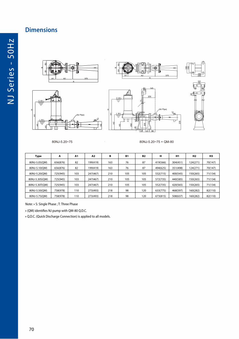
NJ
Seri
es -
50H
z
�0
Dimensions
Type A A1 A2 B B1 B2 H H1 H2 H3
80NJ-5.05(QM) 656(876) 82 199(419) 163 76 87 419(566) 304(451) 124(271) 70(147)
80NJ-5.10(QM) 656(876) 82 199(419) 163 76 87 494(625) 351(498) 124(271) 70(147)
80NJ-5.20(QM) 725(945) 103 247(467) 210 105 105 532(715) 400(545) 150(265) 71(134)
80NJ-5.30S(QM) 725(945) 103 247(467) 210 105 105 572(735) 440(585) 150(265) 71(134)
80NJ-5.30T(QM) 725(945) 103 247(467) 210 105 105 552(735) 420(565) 150(265) 71(134)
80NJ-5.50(QM) 758(978) 110 273(493) 218 98 120 633(775) 468(597) 160(282) 82(110)
80NJ-5.75(QM) 758(978) 110 273(493) 218 98 120 673(815) 508(637) 160(282) 82(110)
Note: » S: Single Phase ; T: Three Phase
» (QM) identifies NJ pump with QM-80 Q.D.C.
» Q.D.C. (Quick Discharge Connection) is applied to all models.
(Air Pipe)
A
BB
2B
1
A1 A2 375
H
H2
180
150
240180
19170
15
H1 L.W.L.
C.W.L.
H3
202 23
5
205
20
8060
145
205
1”
57 123 88
22
18
12
AA1 A2 375
B
B2
B1
H
H3
H1
H2
L.W.L.
C.W.L.H
4
(Air Pipe)
12
80NJ-5.20~75 80NJ-5.20~75 + QM-80
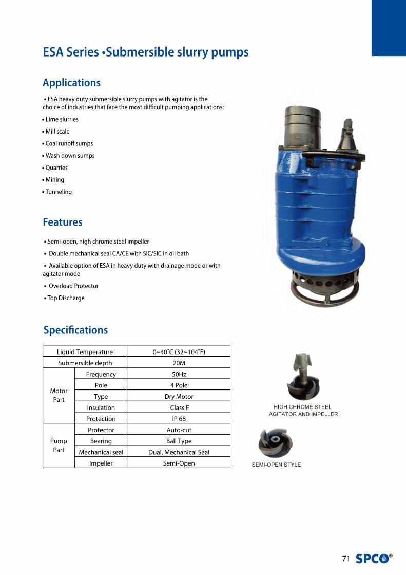
�1 ®
ESA Series •Submersible slurry pumps
Applications • ESA heavy duty submersible slurry pumps with agitator is the choice of industries that face the most difficult pumping applications:
• Lime slurries
• Mill scale
• Coal runoff sumps
• Wash down sumps
• Quarries
• Mining
• Tunneling
Features
Specifications
• Semi-open, high chrome steel impeller
• Double mechanical seal CA/CE with SIC/SIC in oil bath
• Available option of ESA in heavy duty with drainage mode or with agitator mode
• Overload Protector
• Top Discharge
100(150)ESA-5.100~5.150 150(200)ESA-5.200~5.300
H H2 H1
H3
A
A1
B
A
A1
B
H H2 H1
H3
SEMI-OPEN STYLE
HIGH CHROME STEEL AGITATOR AND IMPELLER
26
2922
7
19
5
3
1
17
2423
112
18
1410
15
2016
Material
0~40˚C (32~104˚F)
20M
Frequency 50Hz
Pole 4 Pole
Type Dry Motor
Insulation Class F
Protection IP 68
Protector Auto-cut
Bearing Ball Type
Mechanical seal Dual. Mechanical Seal
Impeller Semi-Open
Pump
Part
Liquid Temperature
Submersible depth
Motor
Part
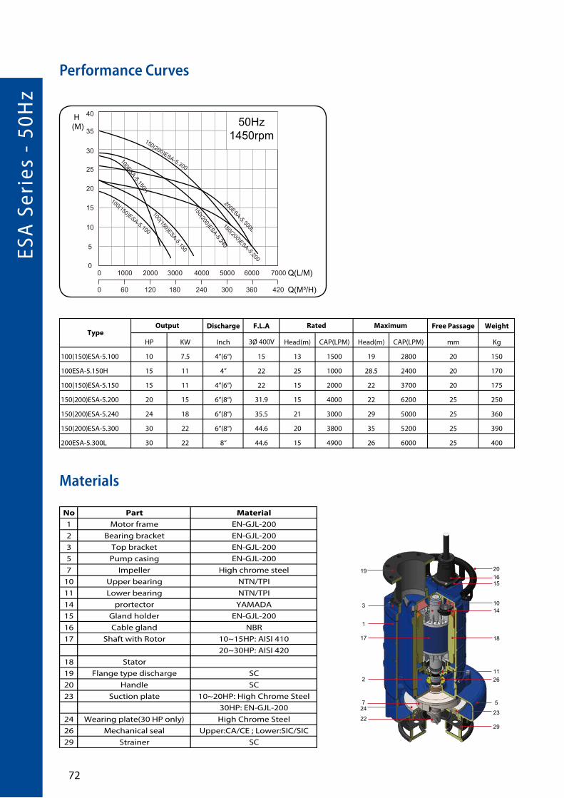
ESA
Ser
ies
- 50
Hz
�2
Performance Curves
Discharge F.L.A Free Passage Weight
HP KW Inch 3Ø 400V Head(m) CAP(LPM) Head(m) CAP(LPM) mm Kg
100(150)ESA-5.100 10 7.5 4”(6“) 15 13 1500 19 2800 20 150
100ESA-5.150H 15 11 4” 22 25 1000 28.5 2400 20 170
100(150)ESA-5.150 15 11 4”(6“) 22 15 2000 22 3700 20 175
150(200)ESA-5.200 20 15 6”(8“) 31.9 15 4000 22 6200 25 250
150(200)ESA-5.240 24 18 6”(8“) 35.5 21 3000 29 5000 25 360
150(200)ESA-5.300 30 22 6”(8“) 44.6 20 3800 35 5200 25 390
200ESA-5.300L 30 22 8“ 44.6 15 4900 26 6000 25 400
Output Rated MaximumType
Materials
SEMI-OPEN STYLE
HIGH CHROME STEEL AGITATOR AND IMPELLER
26
2922
7
19
5
3
1
17
2423
112
18
1410
15
2016
Material
No Part Material
1 Motor frame EN-GJL-200
2 Bearing bracket EN-GJL-200
3 Top bracket EN-GJL-200
5 Pump casing EN-GJL-200
7 Impeller High chrome steel
10 Upper bearing NTN/TPI
11 Lower bearing NTN/TPI
14 prortector YAMADA
15 Gland holder EN-GJL-200
16 Cable gland NBR
17 Shaft with Rotor 10~15HP: AISI 410
20~30HP: AISI 420
18 Stator
19 Flange type discharge SC
20 Handle SC
23 Suction plate 10~20HP: High Chrome Steel
30HP: EN-GJL-200
24 Wearing plate(30 HP only) High Chrome Steel
26 Mechanical seal Upper:CA/CE ; Lower:SIC/SIC
29 Strainer SC

�� ®
Dimensions
100(150)ESA-5.100~5.150 150(200)ESA-5.200~5.300
H H2 H1
H3
A
A1
B
A
A1
B
H H2 H1
H3
Type A A1 B H H1 H2 H3
100(150)ESA-5.100 445 305 370 855 820 720 265
100ESA-5.150H 445 305 370 855 820 720 265
100(150)ESA-5.150 445 305 370 855 820 720 265
150(200)ESA-5.200 520 350 455 1000 950 860 313
150(200)ESA-5.240 520 350 530 1160 1145 1010 330
150(200)ESA-5.300 610 440 530 1160 1145 1010 330
200ESA-5.300L 610 440 530 1160 1145 1010 330

ERS
Seri
es -
50H
z
��
ERS Series • Construction Dewatering Pump
• Double mechanical seal CA/CE with SIC/SIC in oil bath
• Heavy duty with drainage mode
• Protected with Yamada Overload Protector
• Top Discharge
• Lime slurries
• Mill scale
• Coal runoff sumps
• Wash down sumps
• Mining
• Tunneling
Applications
Features
SEMI-OPEN STYLEHIGH CHROME STEEL
7
19
5
3
1
17
23
11
18
1014
26
29
15
20
16
2
24
Specifications
0~40˚C (32~104˚F)
20M
Frequency 50Hz
Pole 4 Pole
Type Dry Motor
Insulation Class F
Protection IP 68
Protector Auto-cut
Bearing Ball Type
Mechanical seal Dual. Mechanical Seal
Impeller Semi-Open
Pump
Part
Liquid Temperature
Submersible depth
Motor
Part
SEMI-OPEN STYLEHIGH CHROME STEEL
7
19
5
3
1
17
23
11
18
1014
26
29
15
20
16
2
24
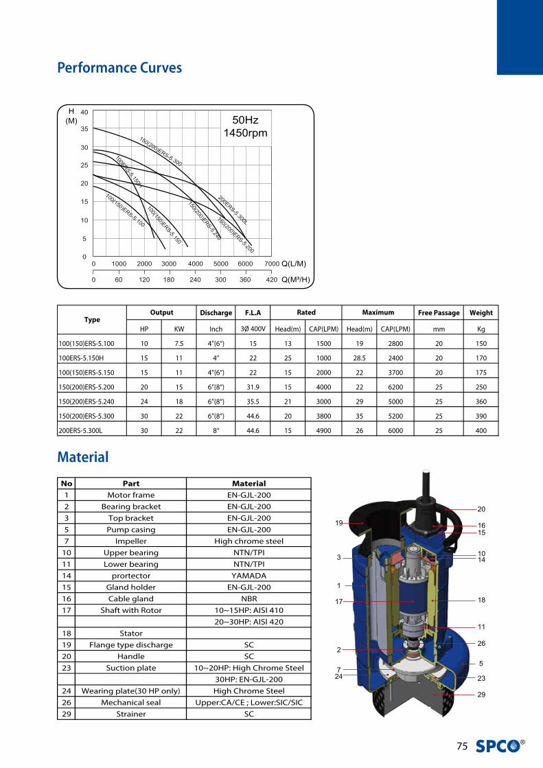
�� ®SEMI-OPEN STYLE
HIGH CHROME STEEL
7
19
5
3
1
17
23
11
18
1014
26
29
15
20
16
2
24
Discharge F.L.A Free Passage Weight
HP KW Inch 3Ø 400V Head(m) CAP(LPM) Head(m) CAP(LPM) mm Kg
100(150)ERS-5.100 10 7.5 4”(6“) 15 13 1500 19 2800 20 150
100ERS-5.150H 15 11 4” 22 25 1000 28.5 2400 20 170
100(150)ERS-5.150 15 11 4”(6“) 22 15 2000 22 3700 20 175
150(200)ERS-5.200 20 15 6”(8“) 31.9 15 4000 22 6200 25 250
150(200)ERS-5.240 24 18 6”(8“) 35.5 21 3000 29 5000 25 360
150(200)ERS-5.300 30 22 6”(8“) 44.6 20 3800 35 5200 25 390
200ERS-5.300L 30 22 8“ 44.6 15 4900 26 6000 25 400
Output Rated MaximumType
Material
Performance Curves
No Part Material
1 Motor frame EN-GJL-200
2 Bearing bracket EN-GJL-200
3 Top bracket EN-GJL-200
5 Pump casing EN-GJL-200
7 Impeller High chrome steel
10 Upper bearing NTN/TPI
11 Lower bearing NTN/TPI
14 prortector YAMADA
15 Gland holder EN-GJL-200
16 Cable gland NBR
17 Shaft with Rotor 10~15HP: AISI 410
20~30HP: AISI 420
18 Stator
19 Flange type discharge SC
20 Handle SC
23 Suction plate 10~20HP: High Chrome Steel
30HP: EN-GJL-200
24 Wearing plate(30 HP only) High Chrome Steel
26 Mechanical seal Upper:CA/CE ; Lower:SIC/SIC
29 Strainer SC

ERS
Seri
es -
50H
z
��
B
AA1
H3
H H1H2
100(150)ERS-5.100~5.150 150(200)ERS-5.200~5.300
A
B
A1
H3
H H1H2
Type A A1 B H H1 H2 H3
100(150)ERS-5.100 445 305 370 790 750 655 242
100ERS-5.150H 445 305 370 790 750 655 242
100(150)ERS-5.150 445 305 370 790 750 655 242
150(200)ERS-5.200 515 350 455 970 940 830 282
150(200)ERS-5.240 515 350 455 1154 1160 1025 345
150(200)ERS-5.300 615 445 530 1154 1160 1025 345
200ERS-5.300L 615 445 530 1154 1160 1025 345
Dimensions

�� ®


Swiss Pump Company AGMoosweg 36
CH - 3645 Thun - GwattSwitzerland
Tel. +41 33 223 11 00Fax +41 33 223 11 22 [email protected]
www.swisspump.com


