Specifications Information and Repair Parts Manual 316A-95, 316B-95, 393A-95, 393B-95, 394A-95, 394B-5, 394E-95, 394F-95, 399C-95
394E-250-00 1 5/2015
Please read and save this Repair Parts Manual. Read this manual and the General Operating Instructions carefully before attempting to assemble, install, operate or maintain the product described. Protect yourself and others by observing all safety information. The Safety Instructions are contained in the General Operating Instructions. Failure to comply with the safety instructions accompanying this product could result in personal injury and/or property damage! Retain instructions for future reference. AMT reserves the right to discontinue any model or change specifications at any time without incurring any obligation.
Periodic maintenance and inspection is required on all pumps to ensure proper operation. Unit must be clear of debris and sediment. Inspect for leaks and loose bolts. Failure to do so voids warranty.
Sewage/Trash PumpsRefer to pump manual 1808-634-00 for General Operating and Safety Instructions.
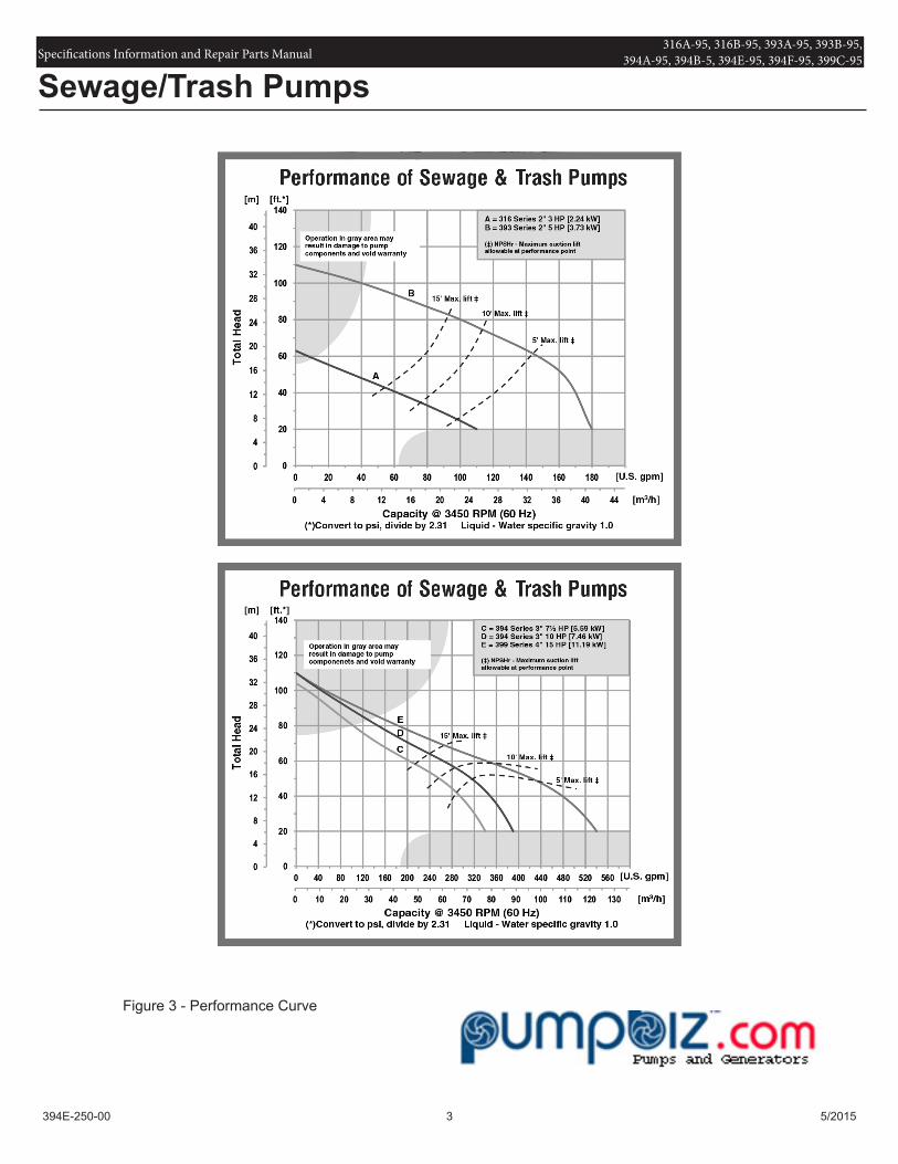
Pumps must be operated in specific ranges as noted on respective curves on page 3 (Figure 3). Failure to adhere to curve will result in damage and cavitation to pump thus voiding warranty.
UNPACKING
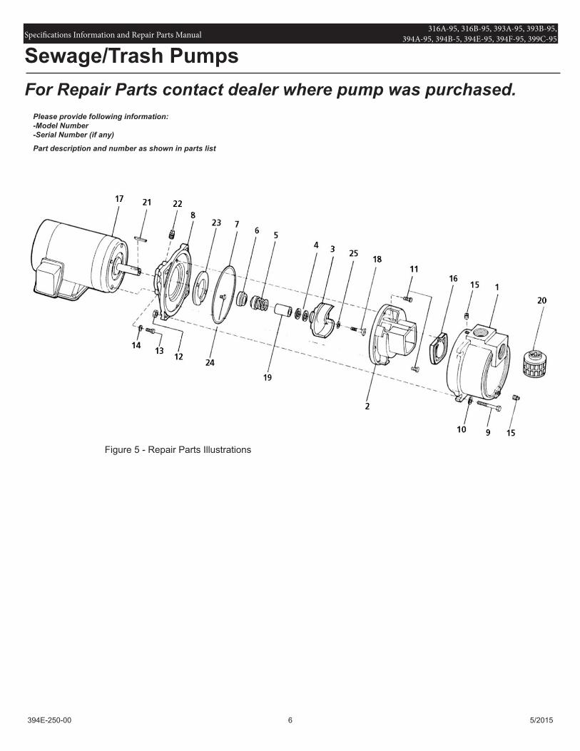
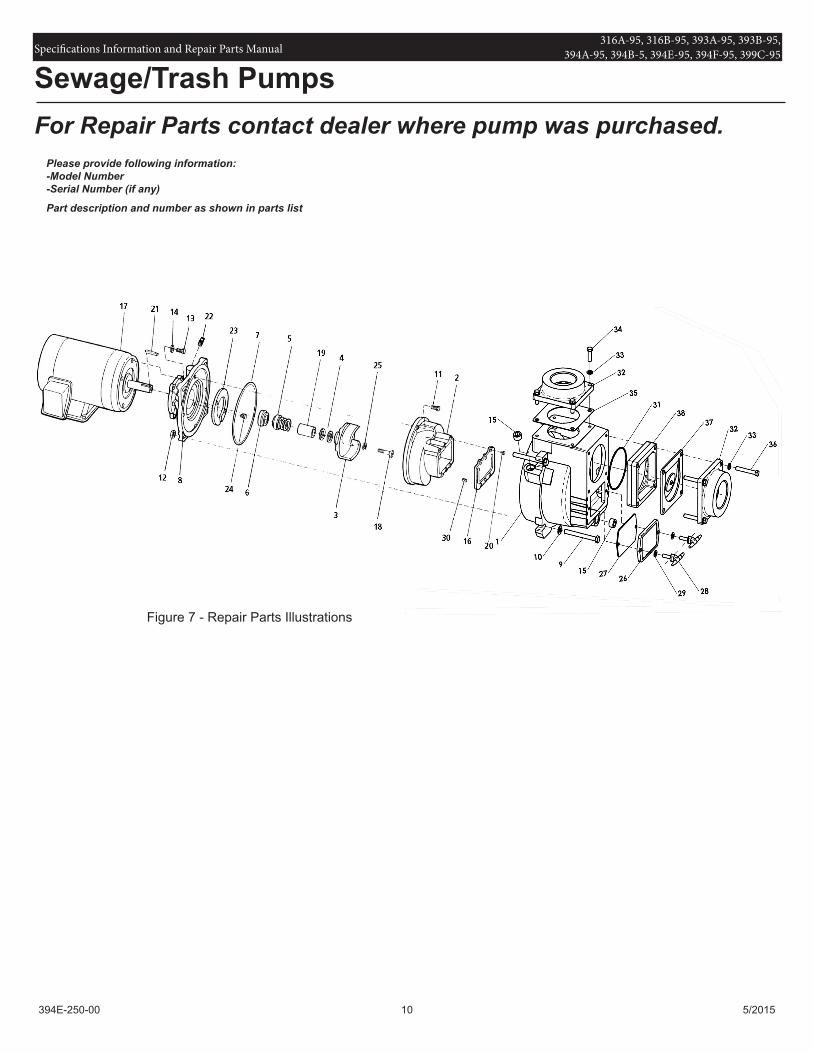
Refer to Repair Parts Illustration and Repair Parts List to aid in identifying parts. Unpack and separate all pump components from container making sure all parts are accounted for.
Package should contain:1. Pump and motor completely assembled.2. Suction strainer.3. Specifications Information & Repair Parts Manual.4. General Operating Instructions & Maintenance Manual.
MAINTENANCE
Note: For information pertaining to the motor and motor parts, consult the motor manual or contact the nearest authorized service representative or the manufacturer.
Make certain that the unit is disconnected from the power source before attempting to service or remove any component.
MECHANICAL SEAL REPLACEMENT
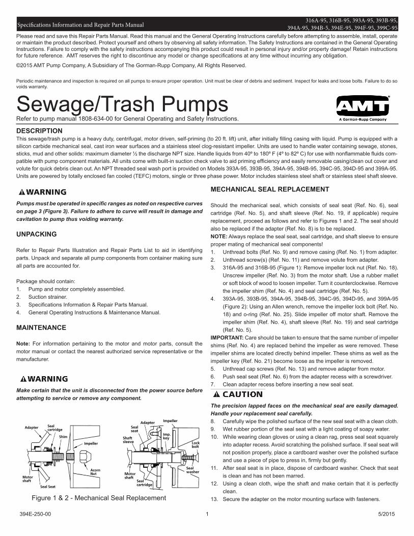
Should the mechanical seal, which consists of seal seat (Ref. No. 6), seal cartridge (Ref. No. 5), and shaft sleeve (Ref. No. 19, if applicable) require replacement, proceed as follows and refer to Figures 1 and 2. The seal should also be replaced if the adapter (Ref. No. 8) is to be replaced.NOTE: Always replace the seal seat, seal cartridge, and shaft sleeve to ensure proper mating of mechanical seal components!1. Unthread bolts (Ref. No. 9) and remove casing (Ref. No. 1) from adapter.2. Unthread screw(s) (Ref. No. 11) and remove volute from adapter.3. 316A-95 and 316B-95 (Figure 1): Remove impeller lock nut (Ref. No. 18).
Unscrew impeller (Ref. No. 3) from the motor shaft. Use a rubber mallet or soft block of wood to loosen impeller. Turn it counterclockwise. Remove the impeller shim (Ref. No. 4) and seal cartridge (Ref. No. 5).
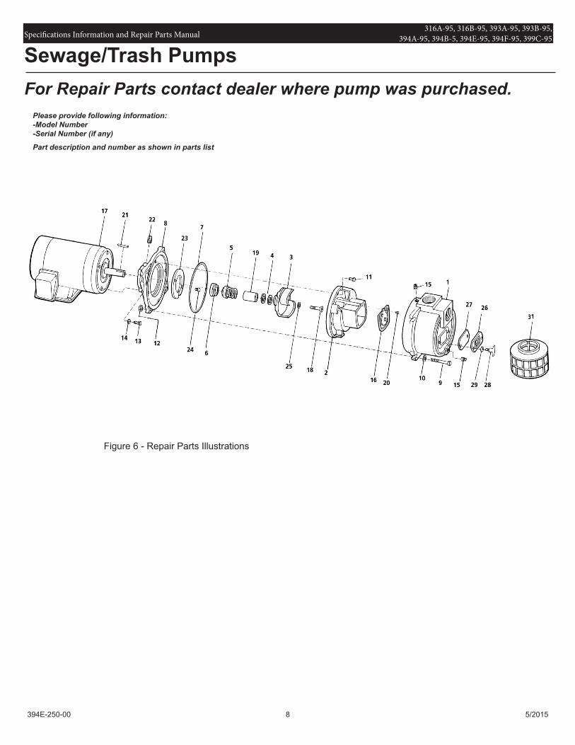
4. 393A-95, 393B-95, 394A-95, 394B-95, 394C-95, 394D-95, and 399A-95 (Figure 2): Using an Allen wrench, remove the impeller lock bolt (Ref. No. 18) and o-ring (Ref. No. 25). Slide impeller off motor shaft. Remove the impeller shim (Ref. No. 4), shaft sleeve (Ref. No. 19) and seal cartridge (Ref. No. 5).
IMPORTANT: Care should be taken to ensure that the same number of impeller shims (Ref. No. 4) are replaced behind the impeller as were removed. These impeller shims are located directly behind impeller. These shims as well as the impeller key (Ref. No. 21) become loose as the impeller is removed.5. Unthread cap screws (Ref. No. 13) and remove adapter from motor.6. Push seal seat (Ref. No. 6) from the adapter recess with a screwdriver.7. Clean adapter recess before inserting a new seal seat.
The precision lapped faces on the mechanical seal are easily damaged. Handle your replacement seal carefully.8. Carefully wipe the polished surface of the new seal seat with a clean cloth. 9. Wet rubber portion of the seal seat with a light coating of soapy water.10. While wearing clean gloves or using a clean rag, press seal seat squarely
into adapter recess. Avoid scratching the polished surface. If seal seat will not position properly, place a cardboard washer over the polished surface and use a piece of pipe to press in, firmly but gently.
11. After seal seat is in place, dispose of cardboard washer. Check that seat is clean and has not been marred.
12. Using a clean cloth, wipe the shaft and make certain that it is perfectly clean.
13. Secure the adapter on the motor mounting surface with fasteners.
DESCRIPTIONThis sewage/trash pump is a heavy duty, centrifugal, motor driven, self-priming (to 20 ft. lift) unit, after initially filling casing with liquid. Pump is equipped with a silicon carbide mechanical seal, cast iron wear surfaces and a stainless steel clog-resistant impeller. Units are used to handle water containing sewage, stones, sticks, mud and other solids: maximum diameter ½ the discharge NPT size. Handle liquids from 40º to 180º F (4º to 82º C) for use with nonflammable fluids com-patible with pump component materials. All units come with built-in suction check valve to aid priming efficiency and easily removable casing/clean out cover and volute for quick debris clean out. An NPT threaded seal wash port is provided on Models 393A-95, 393B-95, 394A-95, 394B-95, 394C-95, 394D-95 and 399A-95. Units are powered by totally enclosed fan cooled (TEFC) motors, single or three phase power. Motor includes stainless steel shaft or stainless steel shaft sleeve.
Figure 1 & 2 - Mechanical Seal Replacement
Jeff
pumpbiz
Specifications Information and Repair Parts Manual 316A-95, 316B-95, 393A-95, 393B-95, 394A-95, 394B-5, 394E-95, 394F-95, 399C-95
394E-250-00 2 5/2015
14. Wet the inside rubber portion of the new seal cartridge with a light coating of soapy water. 316A-95 and 316B-95: Slide cartridge onto motor shaft until cartridge meets seal seat. 393A-95, 393B-95, 394A-95, 394B-95, 394C-95, 394D-95 and 399A-95: Slide cartridge onto shaft sleeve. Slide shaft sleeve with seal cartridge onto motor shaft until cartridge meets seal seat. Reinstall impeller key.
IMPORTANT: Before installing new shaft sleeve, apply a bead of non-hardening, pliable sealant (such as Permatex® Form-A-Gasket® No. 2) to motor shaft shoulder. 15. Reinstall any impeller shims that have been removed. (See “Shim
Adjustment” section).16. 316A-95 and 316B-95: Screw impeller back in place, tightening until it is
seated against shims and shaft shoulder. 393A-95, 393B-95, 394A-95, 394B-95, 394C-95, 394D-95 and 399A-95: Replace impeller key, impeller, o-ring and impeller lock bolt. Tighten lock bolt until impeller is seated against shims and shaft sleeve.
17. Remount volute with fasteners.18. Refer to section entitled Shim Adjustment at this time if shaft sleeve or any
other parts listed have been replaced.19. Inspect position of flapper valve to ensure proper movement and sealing.20. Replace o-ring seal on volute rabbet.NOTE: Always inspect o-ring seals. Replace when cracked or worn. Wet o-ring with soapy water for ease of assembly.21. Remount casing.22. Remount any other parts and reconnect power.
SHIM ADJUSTMENT
When installing a replacement impeller, motor, shaft sleeve, adapter or volute, it may be necessary to adjust the number of impeller shims (Ref. No. 4) to ensure proper running clearance between impeller and the volute wear surface. Proceed as follows:NOTE: Proper running clearance is 0.010”.1. For impeller replacement, add one (1) shim in addition to those removed
originally.2. For motor replacement, add one (1) shim in addition to the shims removed
during disassembly.3. Reassemble the pump as described in steps 15, 16, and 17. (See
“Mechanical Seal Replacement” section).
IMPORTANT: Check the shaft to make sure it is turning freely (rotate the impeller by the impeller lock bolt with an Allen wrench or by the acorn nut with a socket wrench). If it turns freely, check to ensure that the volute and adapter are fitted metal-to-metal where they meet on the outside. If they are not metal-to-metal, tighten fasteners and recheck the shaft for free turning. Tighten carefully, turning the shaft while tightening so that the motor bearings are not damaged in the event that too many shims were installed. If shaft seizes before fasteners are completely tight, disassemble the pump and remove one (1) shim and repeat reassembly.
NOTE: When adding or removing shims, it is best to proceed with a 0.010” increment each time. If motor shaft does turn freely, add shims until it does strike, then remove a 0.010” shim. This will ensure maximum performance.
IMPELLER, WEARPLATE, AND VOLUTE REPLACEMENT
Impeller (Ref. No. 3), wear plate (Ref. No. 23) and volute (Ref. No. 2) are subject to wear only by abrasive sand or sediment laden liquids. If badly worn, all these parts can be replaced easily and the pump thus restored to full efficiency.
NOTE: When the clearance between the impeller and the volute exceeds 1/16” at the face of the impeller or 1/8” on the outside diameter of the impeller, it may be necessary to take corrective action. The increased clearance can cause lengthened priming times and reduce pumping capacity. If both the priming and capacity of your unit are satisfactory for your application, it is recommended that no corrective maintenance be performed regardless of what clearances on your unit may have developed, since the increased clearances in themselves are not generally harmful to your pump.
Normally, new pump clearances can be restored by simply shimming behind the impeller. (Add impeller shims (Ref. No. 4). If the impeller is badly worn, it is recommended that the impeller be replaced. This is usually all that is required since only on unusually abrasive service does the cast iron wear plate and volute show deterioration. Occasionally a stone or hard object might get caught in the impeller and cause damage to the volute. In these cases, follow the instructions below for replacement and refer to the associated Repair Parts Illustration.
1. Disassemble pump for access as described in MECHANICAL SEAL REPLACEMENT, steps 1, 2, 3 and 4.
2. Replace parts as necessary.NOTE: When replacing volute, attach flapper valve to new volute. To replace rear wear plate (Ref. No. 23), remove impeller (Ref. No. 3) and fasteners (Ref. No. 24).NOTE: Before installing new parts, clean all mating surfaces thoroughly.
CLEANING
These units are designed with a removable volute and suction cleanout cover (394A-95, 394B-95, 394C-95, 394D-95 and 399A-95) enabling the pump to be cleaned or unclogged with ease. Remove the suction clean out cover plate (Ref. No. 26) and gasket and/or remove the casing and volute. Remove any debris found inside the unit, reassemble as described in MECHANICAL SEAL REPLACEMENT steps 17 to 22.
NOTE: When replacing clean out cover plate, carefully wipe clean all surfaces on which the gasket has contact. Also, make sure the gasket is in position.
FLAPPER VALVE CLEANING
If debris clogging the flapper valve becomes a constant problem, the flapper area can be cut from the perimeter gasket area and removed from the pump. It is important that the perimeter of the flapper valve remains to seal the inlet area of the casing/volute from the discharge area.
NOTE: Priming efficiency will be reduced if flapper portion is removed.
NOTE: Do not remove entire flapper valve. Perimeter of valve must remain; remove only the flapper area. The pump will not prime and performance will be affected if entire flapper valve is removed.
Sewage/Trash Pumps
Specifications Information and Repair Parts Manual 316A-95, 316B-95, 393A-95, 393B-95, 394A-95, 394B-5, 394E-95, 394F-95, 399C-95
394E-250-00 3 5/2015
Sewage/Trash Pumps
Figure 3 - Performance Curve
Jeff
pumpbiz
Jeff
PB Logo
Specifications Information and Repair Parts Manual 316A-95, 316B-95, 393A-95, 393B-95, 394A-95, 394B-5, 394E-95, 394F-95, 399C-95
394E-250-00 4 5/2015
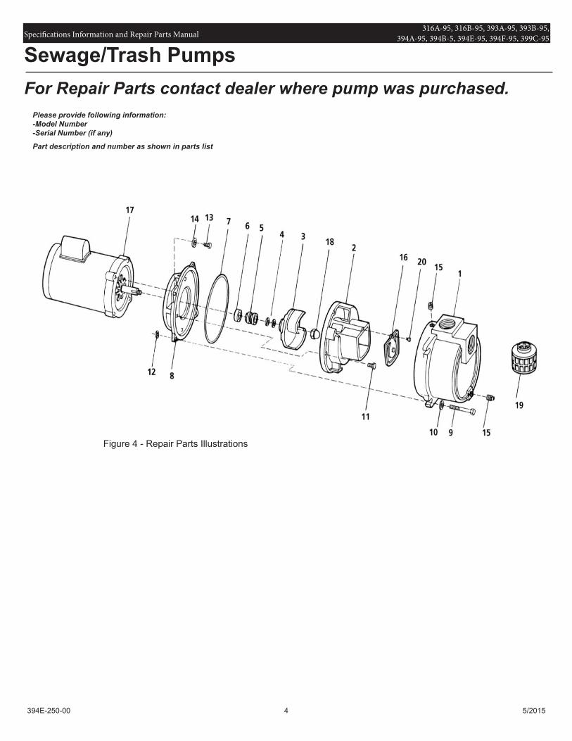
For Repair Parts contact dealer where pump was purchased.Please provide following information:-Model Number-Serial Number (if any)
Part description and number as shown in parts list
Figure 4 - Repair Parts Illustrations
Sewage/Trash Pumps
Jeff
pumpbiz
Specifications Information and Repair Parts Manual 316A-95, 316B-95, 393A-95, 393B-95, 394A-95, 394B-5, 394E-95, 394F-95, 399C-95
394E-250-00 5 5/2015
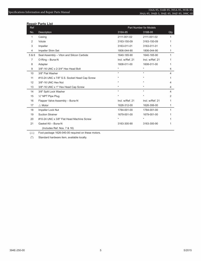
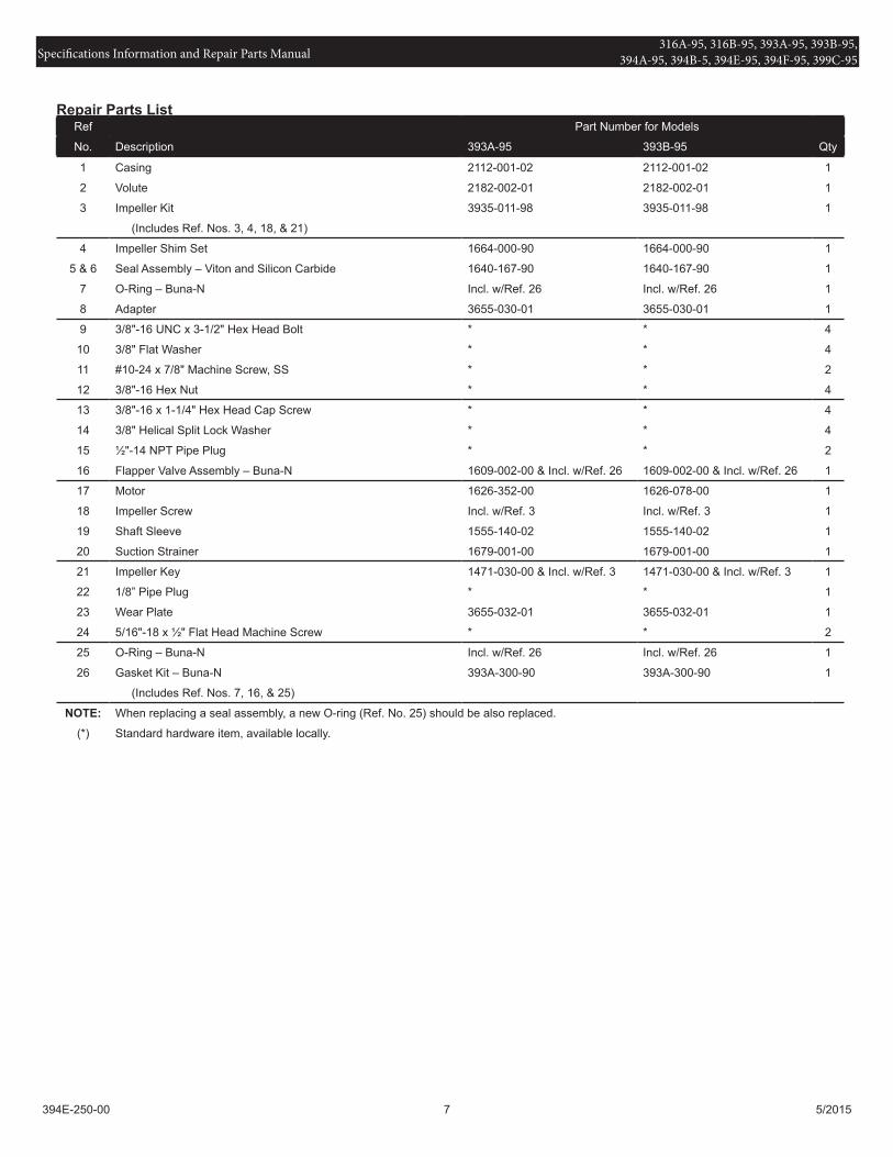
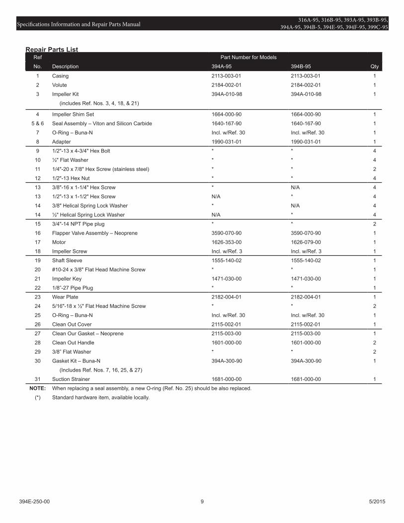
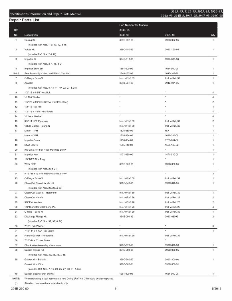
Ref Part Number for Models
No. Description 316A-95 316B-95 Qty
1 Casing 2111-001-02 2111-001-02 1
2 Volute 3163-150-09 3163-150-09 1
3 Impeller 3163-011-01 3163-011-01 1
4 Impeller Shim Set 1806-044-90 1806-044-90 1
5 & 6 Seal Assembly – Viton and Silicon Carbide 1640-165-90 1640-165-90 1