December/January The magazine for the SI TE esr res Tes rious Sinclair user Ghristrmas lights #prom blower & ` 1: Graphics generator ч Joystick сор Spectrum: meméry "s Word Spor sss w ` і = j И, э BETSy ga = = 224 lh і = й 52°, 2 - A У4 — “s ^ я = == =. ` f — ГА і - Y a2 = š Plus latestnews on the hardware -market and tips on do-it-yourself techniques andthe toolsto use
Transcript
December/January The magazine for the
SI TE esr res Tes
rious Sinclair user
Ghristrmas lights #prom blower & ` 1: Graphics generator ч Joystick сор Spectrum: meméry "s Word Spor
sss w
` і = j И, э BET Sy ga =
= 224 lh і = й 52°, 2 - A
У4 — “s ^ я = == =. ` f — ГА
і - Y a2
= š Plus latestnews on the hardware -market and tips on do-it-yourself
techniques andthe tools to use
Do your programs load from tape first time, every time? If not, you need... (1) THEMICROCOMPUTER USER'S BOOK OFTAPE
RECORDING by Hilderbay Ltd.
Contents: PART | (for everybody; the ‘how to' part):
1 How yoursystem should work 2 choosing а tape recorder 3 testing and adjusting your tape recorder 4 keeping your recorder in good condition 5 the selection and care of tapes B making reliable recordings 7 loading difficult tapes Buseful accessories.
PART II (more for enthusiasts; the ‘why’ part): 9 howa tape recorder works 10 computer cassette interface waveforms 11 stereo heads, azimuth angle error 12miscellaneous tape problems.
Price £3.15 incl postage; £2.90 from bookshops. Or ask for itat your library,
(2) TEST AND ALIGNMENT CASSETTE:a precision accessory Which enables you to set up the azimuth angle of your cassette recorder head accurately using only а small screwdriver! Azimuth erroris опе of the commonest causes of tape troubles. With full
structions. £4.90.
(3) LOADING AID: if your recorder is basically OK, but you have. trouble getting the playback level right with tapes from different sources, you need our Loading Aid! Also suitable for checking the. quality of tapes, detecting and (sometimes) compensating for dropouts, etc. With full instructions and hints on tape use. £5.95
(4) TAPE RECORDER aligned and tested for computer use. A simple, but satisfactory, machine. £22 + £2 postage (All products suitable for most computers)
SPECIALTAPE OFFER! Book «alignment cassette + loading aid for £1 1.90!
SPECTRUM SOFTWARE (АВК) PAYROLL (50 employees, all tax codes, pay levels, NI contributions; Hourly, weekly, monthly; payslips, summary of payments; Very easy to use; Amendments to employee details Very easy right up to the last minute; Can also compute gross pay & deductions from net pay), £25
STOCK CONTROL (typically 1500 stock lines; prints list of all lines, or lines with given codes, or understocked lines; locate-by- name/add/delete stock line in under two seconds; prints values of stock, Program loads in one minute, data in less than three). £25.
GOLD our best-selling adventure game, now available on the Spectrum! ЄВ
All these programs are available from stock; we have interesting professional Spectrum software development, but we won't advertise it until we can supply it!
2X-81 SOFTWARE (16-48K) BEAMSCAN, Computers bending moment and shear force diagrams fora simply Suppartedbeam wth 1-99 point uniform, and unormly tapered loads C26. TIME LEDGER or up to Т7 employees, 200 chents. А great ime-saver E15 OPTIMAX.A powerlullnear optimisation program, Upto 75 variables <= constraints C40. PAYROLL Similar tothe Spectrum version but 30 employers £25 STOCK CONTROL about 400 stock hnes in 18K. 2000 m 48K) £25 CRITICAL PATH ANALYSIS. Enter & solve SOO-sctwiy network in 16K. Edit durations costs, repeat £18 BUDGET. Keeps track of expenses & compares them with budget. SO headings, 12 manths lj ar 12 categories 1) £ 15 forbudgetl& 1 (together) FINANCIAL PACKI. Contains throe programs MORTGAGE, LOAN, МАТ £8 GOLD. A tantalising adventure game! £6 Free GOLD 2X-B1 or Spectrum) withall orders of £22 or over postmarked before Decem з Allpricesinclude VAT Everything post réunies stated otherwise СОО orders £2 ача Access orders accepted by telephone. Hilderbay Ltd Professional Software. 8/10 Parkway Regents Park London NW1 7AA To01-885 1059 Tic 22870
Keyboard with Electronics
= EE, A häl size, fditrave 43key keyboard that's simple to add о your ZXB) and requies no soldering in the ТУВ] Complete with the electronics to make "Shift Loci single key selections making entry lar easier. Powered from 2X81 s own standard power supply -with special adaptor supplied. Two colour print for key caps.
low price for complete bud it yourself ki, озү £18.95 incl. VAT and carriage. Order Аз ТОР Һа detas in the June 1982 isse of "Bectronics -The Maplin Magazine” on sale at all good newsagents price Б In case of ойу send 0р to address below, си E240 for annual subscription М issues
KEMPSTON (Micro) ELECTRONICS ZX81 Klik-Keyboard This is a full, forty key, moving keyboard. which fits into the recess left after peeling off the existing "touch:
lowing advantages: Positive feedback trom keys Fits onto the 2X81 No trailing wires. No special case needed Elegant design with two colour legends $ The fully built keyboard requires absolutely no soldering since two fk connectors plug into the ZX81 sockets. Alternatively, the keyboard is available as
an easy build kit at a considerable saving. Now available with 41 keys, the extra key can be used to give a repeat facilty.
E Spectrum Joystick complete with interface and full instructions for use in вас 19 50те VAT
€ Allprices inclusive of VAT, but postage must be added at 70 pence fora single tem, 100 pence for 2 or more items. Payment by cheque or P.O.
Available by mail order from: KEMPSTON (Micro) ELECTRONICS
180A Bedtord Road, Kempston, Bedford MK42 ВІ. Please allow 21 days for delivery. S.A.E. in all correspondence.
Your Name and Address SUB
Description Unit Price Amount Spectrum Joystick.
X81 Kok-Keyboard built 41 keys
Postage
a i sine lei or ges
A р
5 CLUBS Help with problems сап be obtained from some ofthe user groups throughout the country
NEWS The latest on what peripherals are being launched
HOW TOSOLDER An easy guide to basic techniques
10
12 JOYSTICK CONTROLLER How to build a simple control for the Spectrum
WORD PROCESSOR Some routines to improve text handling
LATCH CARD This enables the ZX-81 to drive a power card which can be put to various uses
CHRISTMAS LIGHTS A Power Card to drive lightson a Christmas tree
GRAPHICS GENERATOR Asimple card to allow users to define their own graphics
17
20
24
29
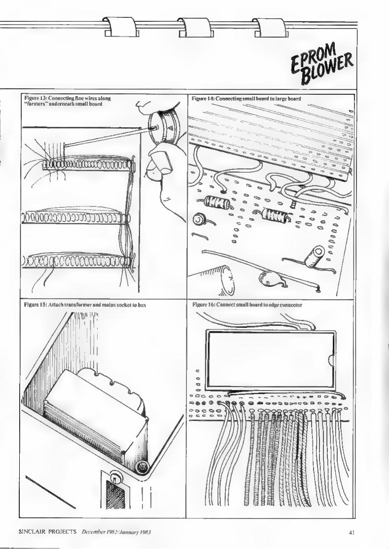
34 EPROM BLOWER How to program an EPROM
TOOLS A survey of the tools you will need in adapting your machines
42
47 EDGECONNECTOR Our regular page illustrating the
FROM THE EDITOR INCLAIR PROJECTS is unlike any magazine on the market. It aims to cater for those who posses:
Sinclair computer and are beginning to become illusioned with playing Space Invaders and are соп-
vinced deep down that the computer is capable of much more.
Each issue of Sinclair Projects will present a number of graded projects designed for a spectrum of users from the absolute beginners to those who are highly competent at do-it-yourself electronics. We will also be printing a series
teaching the complete novice how to choose a worthwhile set of toolsand even how to solder.
The projects in the first issue start with a very simple board which will allow a range of applications to be covered in future issues. The first board to be plug; this input/output card is a power controller. whi permit you to control anything from sets of Christmas lights—just to be topical—to train-set points to domestic lighting.
Yet another project will allow you to build a joystick controller for either the ZX-8 | or Spectrum, thusallowing easy control of cursor position on ine,
The two major proje, s iss hardware—are really for those who kno what ү аге doing. We take the EPROM blowcr project which won the competition recently in Sinclair User and de: how you can build it. The major software project looks at how you can use the Sj 1
Other pages in comprehen- sive round-up of new hardware plug-ins on the market and a look at some computer clubs which offer advice and helpon building projects,
The next issue, in January, will consider some exten- ions of projects in this issue and will also bring you up-to-
date with some of the new hardware releases which make at Christmas.
In common with most magazines in this field we wel- come comments, criticism, ideas for future articles and even articles. We have appointed a group of techn
sessors whose job is to evaluate cach project as it is received to build it and test it so that we know it works before we publish it. If you have a project you would like to submit, please send it to the editor. Each project should
Sterlicchi Advertisement director Simon Hors Editorial production assistant Margaret Hawkins
Sinclair Projects is published monthly by ECC Publications Ltd. Telephone all departments: 01-359 7481. If you would like to co
ims, articles ог ideas for hardware projects to Sinclair Use uy £50 per 1,000 words for each article used.
" cost less than £20 and use commonly-available connections from both the ZX-81 and the component: i Spectrum We wish you а merry Christmas—and get out those
soldering irons. Editor Nigel Cla ‘Consultant raer Robin Bradbeer BSc(Hons). MPhil, CEng. MIEE. MInstP Technical assessors Richard Li Whittle BSc, Dave Butcher Production editor Harold Mayes MBE Design Elaine Bishop
Advertisement manager John Ross Advert ingdirector Terry Cartwright Chairman Richard Hease in no way connected nclair Research Ltd. tribute to any of the Sinclair User group of publications please send
ions. 30-31 Islington Green, London N1 BJ. We
peset by Bournchall Press Ltd. Welwyn Garden City, Herts, Distributed by Spotlight Magazine Distribution Ltd. 1 Benwell Road, Holloway. London N7.01-607 6411.
SINCLAIR PROJECTS December 1982 January 1983
We've got big ideas about you and your
. Sinclair / ISIS Because we know you're always looking for
/— new ideas to make the most of your Sinclair computer, we'remaking sure younever runout
of steam!
Just announced - and due out in December — is Sinclair Projects magazine, full of fascinating
schemes to tax your skills and reveal the practical potential of your Sinclair in applications like соп-
trolling lights, upgrading computer graphics, house- 7 hold security, and many more.
Whether you're new to computing, oran old hand, you're certain to be an enthusiast. That's why we introduced
Sinclair User magazine for the latest news, techniques andenhancements tomatch your enthusiasm(now with new
"Spectrum User’ supplement!) Next, its companion magazine, Sinclair Programs, became an overnight success with 40 NEW programs, ready for you to key, in every issue, Now the exciting new Sinclair Projects completes your store of possibilities witha huge increase in computing potential for you
to explore.
Sinclair Projects is published on alternate months to Sinclair Programs, so there's always something new to test your skill. But
here's the best news: when you subscribe to all three Sinclair magazines, you get the first three issues of new Sin- clair Projects absolutely free!
езіглє-ієвій Argeck
ч "
Weknow you'vegotbigideas about your Sinclair. Make sure you live up to them with threefold computing pleasure. Fill out the order form now and we'll send you the first ideas-packed Sinclair Projects — hot off the press.
Mail to: ECC Publications Li 'd; 30-31 Islington Green,
London N1 8ВЈ
Sinclair User / Spectrum User; Sinclair Programs; Sinclair Projects
Yes - I'd like to subscribe to: (1 Sinclair User (12 issues - price £9.00) including special ‘Spectrum User’ supplement in each issue.
17 Sinclair Programs (6 issues — price £6.60) | Sinclair Projects (6 issues - price £6.60) Remember you get the first three issues FREE if subscribing to all
three magazines! D lencloseachequeforg | — — .— — — (deduct £3.30 from total costif subscribing toall three publications) [ 1 Please chargemy creditcard Cardname Number Name Address
Signature Date NB This offer applies to UK subscribers only. Overseas rates available on request.
n
a
HERE ARE more than 300 Timone clubs in the U.K.
That does not include the machine-specifie groups like the national ZX Users’ Group, which organises on a national basis. Most of the clubs are based on small groups of people, usually fewer than 100. who meet regularly in college rooms, libraries or even upstairs pub rooms.
If you have a computer, it is recommended that you join a local group as well as any national ones. In Club Spot cach month we plan to look at some of'the local clubs which cater forthe typical reader.
Most clubs are good for those who know nothing about com- puters and want to pick a few brains before buying one, or for comparing new programs or even swapping them with like-minded users. What most do not cater for is the hobbyist interested in building bits and pieces to add on to their computers. The few who do will bethe subject of this section.
The national group which co- ordinates the activities ofall the local clubs and the majority of the national user groups is the ACC, It used to be called the Amateur Computer Club but a recent name change to ACC is an attempt to broaden its influence and.take account ofits new role.
The interests of the ACC are far-ranging and not tied to any one type of computer. micro- processor or manufacturer, |l is consequently ап ideal complement lo the dedicated user groups which are formed for specific machines. It provides an insight into the many aspects ої microcomputers which otherwise might be ignored.
Since its formation in 1972. the ACC has published a news- letter. now called 4CCumulator. In
Clubbing together for mutual support
the days when most people were scarcely aware of the giant main- frame computers. the ACC was the only computer club in the world and it can now claim to be the first computer club of all. ACCumulator was for five years the only magazine in Europe for the amateur and small business user.
With few commercially-made sys- tems available. АЄСптийшог con- lained designs for complete com- puters, as do it yourself was the only way. and contained help- ful articles for people building or repairing their systems.
That favour of hardware designs
ACC has been a regular feature at computer shows for several years. Ex- hibitors regard it as the central contact for personal com- puter users.
and systems programming is main- tained today, as the ACC is the only group catering for the so-called homebrew enthusiast. Yet the wealth of knowledge and expertise built from the early years has been vital for newcomers to computing and now 1CCumulator. reflects the changing
scene. with information and com- ments on a selection of the latest machines to reach the market. In the last year low-cost designs have been published for a micromous four computers. an Epromulator. а programmable character generator. A/F and D/A converters, and a light pen
The ACC is not limited only
to a magazine. As membership grew, people joined to form local clubs and thus built the foundations of the now country-wide but still expanding network of groups. The ACC maintains a database of those groups and that is made avail- able at exhibitions to keep people in touch with the activities in their areas. The database was also used by the BBC to form the basis of its Referral Service. The ACC continues to pro-
vide help and service to the local groups. many of which have appointed an ACC repre- sentative—at a reduced subscription rate—to maintain close links directly with the committee, Also a reduced
с bulk subscription is available for clubs. They may then use 1CCumulator to increase the size and diversity of their news sheets or relieve themselves entirely of that sometimes difficult task.
The ACC has been a regular feature at computer shows for several years. Exhibitors and | national organisations regard it as the central contact for per- sonal computer users. The organisation advances with
changes in technology and has held conferences on robotics and com- munications, formed a specialist robotics group. and maintains а number of news and information pageson Preste
The ACC is not a one-man band and is run by a committee elected democratically at the annual meeting. Run entirely by volunteers. the ACC remains the lowest-cost and best-value computer group, with a 1982 subscription of £5. To join. send your name. address
and subscription to The Membership Secretary, Rupert Steele, St John's College. Oxford. OX 1 ЗІР. |
SINCLAIR PROJECTS December 1982 January 1983
x: XC Tanaman,
=i == EAS
news Data loss threat
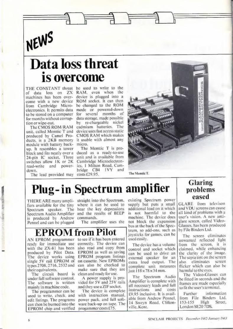
is overcome THE CONSTANT threat
of data lo: on machines has been о come with a new device from Cambridge Micro-
It permits data
to be stored on a computer for months without corrup-
unit, lled Memtie T And produced by Camel Pro- ducts, is a 2KB | memory
up. It re block and fi ly overa 24-pin IC socket, Three witches allow IK or 2K
l-write and power- down.
The lead provided may
a tower
be used to write to the RAM. even when the device is plugged into a ROM socket. It can then be changed to the ROM mode or powered-down for several months of
lata storage, made possible nickel
mium batteries. The хе uses fast access static
CMOS RAM which makes it usable with almost any micro,
The Memtic T is pro- duced as a ready-to-use unit and is available from Cambridge Microelectron-
ics, | Milton Road. Cam- bridge CB4 IVY and costs £29.95. The Memtic T.
0 0 2 00 br B 20|
B5 50 | K: 2
Plug- in Spectrum ARE many ampli- lable for the tiny
speaker. The Spectrum Audio Amplifier is produced by Andrew Pennel and can be plugged
straight into the Spectrum, where it can be used to hear the key depressions and the results of BEEP commands.
The amplifier uses the
EPROM from Pilot AN EPROM programmer ready for immediate use with the ZX-81 has been produced by Pilot Data. The device works using single 5У rail EPROM of types 2708, 2716, 2532 and theirequivalents.
The circuit board is under full software control. The software is written mainly in machine code.
The programmer can be used to write, check, and edit listings. The programs can then be burned into the EPROM chip and verified
it has been entered correctly. The device can also read and copy from EPROM as well as saving EPROM program listings on cassette. New EPROMs can also be checked to make sure that they are clean and ready for use.
power supply is vided for 5V and and they usea ZIF:
The device is complete with instruction. manual. power pack. and full soft- ware back-up on tape. The progammercosts £7.
amplifier existing Spectrun supply but pui additional load on it which is not harmful to the machine. The device doi not block the expansion busat the back of the Spe trum, so add-ons, such as joysticks for games. can be used easily
power
The device has a volume control and socket which can be used to drive external speaker for an extra loud output. The complete unit measures just 18x78 x34 mm.
The Spectrum Audio Amplifier is complete with all necessary leads and full instructions and costs 59.95 inclusive. It is avail- able from Andrew Pennel, 14 Sweyn Road. Clifton- ville. Kent.
Glaring problems
eased GLARE from televison and VDU screens can cause
all kind of problems with a user's vision. A new a glare screen, Glasses. has been produced by File Binders Ltd.
The ser en eliminates unwanted reflected. light from the sereen, it is claimed. while enhancing the clarity of the image. The sepia tint on the screen also eliminates screen flicker which can also be harmful to the eyes.
The Video-Glasses can be fitted in seconds and the frames are made especially то it the user'sterminal.
Further information from File Binders Ltd. 153-155 High Street. London SE20 7DS.
6 SINCLAIR PROJECTS December 1082 January 1983
NEWS Colourful registers on market
TWO NEW registers are to be published listing sup- pliers of Spectrum. pro- ducts in the U.K. The ZX Spectrum. Guide is. from Youngs Computer Publi-
tions, Which released the -80/81 — Register іп
1982, The new Spectrum guide will include a list of soliware available. publi- cations, hardware, and other items,
Youngs is considering compiling a supplement or new edition of the ZX-80/81 Register to bring
publication up-to-date and preparing supplemen- tary editions on computer shops and domestic pro-
ams The guides will be
available from Youngs Computer Publications. 2 Woodland. Gosfield.
alstead. Essex, CO9 ITH. The prices for the guides have not yet been decided.
The Guide tò Spectrum Resources has been pro- duced by the organisers of the Micro Scene Brum 82. It follows the EZUG Dire tory of ZX Suppliers which was published carly in 1982 but it is a general guide and not related to its educational counterpart.
The Micro Scene guide will contain details of sup- pliers of Spectrum pro- ducts, Spectrum books with reviews, software and hardware. and miscellan-
us suppliers and services. he guide will be obtain-
able from Micro Scene. 6 — Battenhall Road. Harborne, Birmingham. BI7 9UD and will cost £2.50
Spectrum speech pack THE COMPANY which introduced Speech Packs for the ZX81. DCP Micro- developments, has upgrad- ed its products for use оп the Spectrum. The Spectrum Speech Pack includes all the features found previously in the ZX-8l version, including ZX Connector. built-in speaker. volume control and expandable vocabu- lary. It is controlled by the Spectrum OUT command. followed by a number which indicates the word to be used.
he Speech Pack plugs directly into the rear of the Spectrum. The ordinary Spectrum power pack can be used with itand no extra equipment is needed. The ZX printer and other peripherals can be added onto the back of the unit.
The unit is accompanied by Word Pack ROM One which contains all the letters of the alphabet, numbers from zero to more than one million and other words and sounds. Three more plug-in ROM packs can be added to the speech pack at any time to expand the machine vocabulary to hundreds of words, The Spectrum Speech Pack costs £49.95 and additional word packs £14.95 each.
The Inters а new interface for the Spectrum. It adds on to the rear of the Spectrum and provides interfaces for such peri- pherals as joysticks or
t sensors, The device four relay outputs for
high current control. four switch inputs buffered for connection to contacts, and eight-bit input and output
ports which can be used for home-built dev The Interspec unit
includes the DCP bus, an expansion system using a 15-way connector which can control up to four more peripherals or. if a few additional components are added, up to other devices. The unit is pro- grammed using the IN and OUT commands of the Spectrum. lt costs £39.95,
The DAC Pa plugs into the DCP s of the Interspec. an eight-bit | digital-to- analogue converter with an output range of 0 to 2.55V. Other units compatible with the DCP bus can be connected to the DAC pack, which costs £14.95, All the devNorwich, NR13 4AX.
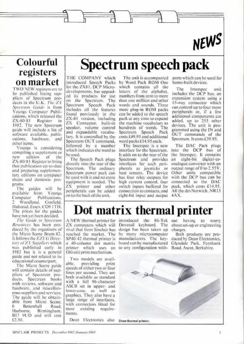
Dot matrix thermal printer A NEW thermal printer for ZX computers which will rival that from Sinclair reached the market, The $Р40/42 thermal printer is a 40-column dot matrix printer which uses an Olivetti print mechanism.
Two models are avail- able. providing print speeds of either two or four lines per second. They are both available as standard with a full 96-character ASCII set in upper d lower-case. as well graphics. They also have а
we range of interfaces, with connectors fitted for most existing require- ments.
Dean Electronics also
introduced the Hi-Tek Dovetail keyboard. The design has been taken up by many microcomputer manufacturers. The key- board can be manufactured to any configuration with-
Dean thermal printer.
ош having to worry about set-up or engineering charge:
Both products are pro- duced by Dean Electronics. Glendale Park, Fernbank Road. Ascot, Berkshire.
SINCLAIR PROJECTS December 1982 January 1983
Tracing the Spectrum IT IS now possible to draw maps. technical drawings, portraits and even cartoon characters in full-screen high-resolution with the Spectrum, using the mini- mum of memory and pro- gram code, The hardware device which permits the Spectrum to be used as a drawing pad is called the RD Digital Tra It resembles a horizontal mechanical arm which can be guided over pictures. As the arm traces the original picture on the board the picture will be transferred to the Spectrum screen. The pictures can then be copied to the printer or saved on cassette for recall ata later date,
The device consists of a mechanical digitiser which can be put on toa desk о drawing board. The Tracer can draw over an area
approximately 300 x 200 mm., though bigger ver- sions are available to special order.
Software is also supplied with the Tracer which will enable outline drawings to be made quickly and easily and then shaded. The dis-
RD digital tracer.
play file can also be saved for merging with the user's own programs.
The RD Dig costs £49.95 and is avail- able from RD Laboratories. 5 Kennedy Road. Dane End. Ware, Herts, 5012 OLU.
Electronics on show AN EXHIBITION for electronies hobbyists is to be staged at the Royal Horticultural Hall, London for four days from Novem- ber 10. Called Breadboard. it has been planned by Argus Specialist Publica- lions, publisher of Computing Today
Peter Freebrey. ап organiser. said that it has a mainly electronics base but there will be some com- putersat the show. One feature will be the
computer corner which will have a 2Х-81 and Spectrum on display. The idea of the corner is to allow people who have never used computers pre-
viously to have hands-on experience,
г Research will not be at the show. The reason seems to be that the show is expected to attract elec- tronics rather than com- puter hobbyists.
Among the exhibits will bea feature on war gaming. with two computers play- ing а war game with each other. An exhibition of holograms — three-dimen- sional images created by light patterns—will also be on view.
The show will be centred on the Royal Horticultural New Hall in Greycoat Street—not in Vincent Street.
Portable Sinclairs
USERS of the ZX-81 and Spectrum sometimes need to take their machines to clubs and exhibitions, Now
Computer Aided Design has produced a range of products. called Jigsaw. which will make it easier. The range includes an
attache case and an inter- face connector. The attache case will have com- partments fora RAM pack. a keyboard, floppy discs. printer. flat-screen tele vision, cassette players.
modem and rechargable battery. as well as space for the ZX-81.
Contact Computer Aid- ed Printing Services Ltd, 28 The Spain, Petersfield. Hampshire. GU32 3LA.
Promoting Alpha on EPROM
CAR MANUFACTURER Alla Romeo is using a very interesting device in its sales promotions. H is a ZX-81 with — external EPROM attached. The
ROM is being manu- factured by Capital Com- puters and Abies Infor- matics has provided the program.
The control program is based in an EPROM cart- ridge programmed in Basi That is unusual, because EPROM programming has usually been. done in machine code. The pro- gram is burned into the EPROM and can be erased only by using ultra-violet light.
When the ZX-8l is switched-on the program is loaded automatically into the RAM of the ZX-81, All the salesman has to do then is to follow the program prompts.
Capital Computers plans to put the device on the
ket and sell it to ZX users. There will be a series of EPROM cartridges to go with the machine, which will then have the same ability as the Vic and Atari computers to use cartridges asan alternative to cassette. Programs will be available instantly from power-up. so the user will not have to worry about manual loading.
Further information on the EPROM can be obtain- ed from Capital Com- puters, 1 Branch Road. Park Street, St Albans ALI ARI.
SINCLAIR PROJEC December 1982 January 1983
А Y
NEWS ZX-81 programs for the Spectrum
THE PROBLEM of load- ing ZX-8l programs into the Spectrum has been eased by East London Robotics. It seemed to be insoluble when the first Spectrums left the produc tion lines. Even Clive Sin- clair said that because of the difference in the transfer baud rate of the machines and language in- compatibilities, loading ZX-81 programs directly on to the Spectrum was something which could not be done. Theansweris in the form
of a hardware device, together with a control pro- gram. To load a ZX-81 pro- gram, the control program
must first be loaded into the Spectrum. The ZX-81 pro-
n can then be loaded on to the Spectrum Бу fol- lowing the prompts given by the Slow Loader control program. Those prompts appear in the form of several menus of options. The user selects the options, depending on how the incompatibilities are to be dealt with.
The — incompatibilities between the machines include SCROLL and graphics characters on the ZX-81 and the INVERSE command on the Spe trum. The Slow Loader uses machine code routines to deal with all the prob-
lems except for INVERSE. which cannot be translated.
East London Robotics also produces 64K of add- on RAM for the Spectrum. It takes the Spectrum mem- ory capacity up to 80K. The memory is put under the keyboard into the sock- ets which are provided for the Sinclair 32K memory add-on.
Both products are avail- able from East London Robotics, Finlan 14 Darwell Clos Ham E6 4BT. The Slow Loader costs £10 and 64K RAM costs £50. The RAM
ailable as a kit for £44.
Non-wobble RAM A NEW RAM designed to elimini RAM wobble and dis nection problems ha produced by Ground Con- trol. The company si that the ZX-81 can bi picked up and shaken and the RAM pack will stay in position. The RAM are manufactured by injec- tion moulding so that the contours of the case are absolutely correct for fit- ting on to the ZX-81. Each 16K unit costs £19.95. Ground Control also
providesa keyboard sound- eras an optional extra. The sounder is fitted inside the case to permit the user to enter programs faster and with more accuracy, as it gives an audio feedb: when a key is pressed. The company also says that the
k device a so helps to reduce y in because the user
does not have to look at the. keyboard so often to check whether a key has been pr
The distributor claims a fast turnover of orders. For credit-card — transactions, Ground Control RAM pack.
units will be mailed by return of post and for cheques and postal orders deliveries should be made within four day
Further information from Ground Control. Alfreda Avenue, Hull- bridge. Essex, 555 6LT.
Sinclair market expands rapidly INCLAIR market is
still expanding rapidly and ies are produc-
ing add-ons and software every month. Compani are dealing more in tl Spectrum but sales of ZX-8 |sarestill increasing.
The ZX-81 is now of interest to electronics hobbyists who can use it to discover more about com- puter architecture, Companies have been set
up to try to cope with the demand for Sinclair pro- ducts. One is Prism Micro- products. which has more than 200 retailers through- out Britain, At the moment Prism is responsible for
olesaling the ZX-8l. printer and software but managing director Bob Denton hopes to be selling the complete Sinclair range
also receiving samples of products from other companies in the Sin- clair market. Denton wants to sell the best of them through Prism in an effort lostandardise the market.
He also wants market its own Spectrum products y would be produced by independent companies and individuals espe for Prism, w isas company of ECC Publica- tions. which publishes Sinclair Projects.
In addition. the number of national chains stocking the ZX-81 is growing. Apart from W H Smith, it is be- ing sold by Boots, Dixons, Rumbelowsand Wiglalls.
SINCLAIR PROJECTS December 1982/January 1983
а= Wa j
onhowto make itseem easy.
OLDERING із easy, isn't it? Ss tis once you can do it but
at first. it seems almost impossible, The best to learn to solder is to watch somebody who does it well and then to try it yourself while they see where you are going wrong.
Nevertheless, 1 will try to tell you how to make good soldered joints without ‘frying’ your components,
sistors—and fingers. ‘Of the things you need, the most
important tool obviously is the sold- ering iron. For working on printed circuit boards, Veroboard and the kind of circuitry we are concerned about, I suggest you use а small light- weight iron of no more than 15 watts power. I use both an Autex C-240 with “a2 in., 32 in. and 5/2 in, bi and а low-voltage Oryx 6V 6-watt miniature soldering iron for really small jobs. Other manufacturers pro- duce equally suitable small light- weight irons. 1 also suggest you buy а soldering iron stand as well.
You many wonder why I use three
Figure 1
Je chan a component lead:—
different sizes of bit. The answer is that the bit is a store of heat and the bigger the bit the more heat it stores, so if I am making very small joints I
Soldering on to a perfect finish
The ability to use a soldering iron is of major importance in should be suitable, provided it is a
any electronic projects. David Elbee gives a simple guide small diametersize.
use the !/zin. bit and for larger ones on switches or terminals I use the 5/заї п. one. If | use the !/azin. one on
large joints all the heat flows out of the bit into the joint and there is not sufficient to heat the joint and bit to a high enough temperature for the solder to flow. 1 know the soldering iron bit is being heated by the electric element in the iron but that is being done only slowly and we need fast heat transfer to the joint, or we can
over-heat the components being soldered. On the other hand, if I am making very small joints the 5/azin. bit is often too big to reach the joint without touching something I do not
want it to touch. For soldering electronic compo-
nents we need to use a good quality resin-cored solder made specially for electronics work. The resin core, when heated by the soldering iron, melts into a flux which helps heat transfer to the joint and mildly cleans and protects the components from the air while they are being soldered, and because when the joint has cooled the flux has solidified in all the nooks and crannies it is vital that it does not contain harmful chemi- cals which must be washed away.
The cored solder which you can buy from a local ironmonger may or may not be satisfactory but I wouldn't use it, 1 use Ersine Multi- core five-core solder in a 0.71 mm.
size but any cored solder you buy from a reputable component supply
shop or radio/TV repair shop
A damp paper towel is needed to clean the hot bit before starting to
solder and to clean the flux from the bit after each joint before you return
the iron to its stand. Soldering iron stands usually have a piece of sponge. but I prefer the damp towel.
I never usc heat shunts; most com- ponents will tolerate their leads being
at the temperature of molten solder for five to 10 seconds and that is ample time to make a soldered joint.
Some people would say you need а small pair of round-nosed pliers or tweezers for bending component leads. They are useful to have but
most times I just bend the leads with
my fingers. An ink rubber is useful. If you
Figure3
all silver with solder
Tn soldering ron bit.
make a slit in one and draw a com- ponent lead through it—figure one— it will clean-offall the dirt, grime and grease from the lead. Normally that is unnecessary but sometimes a batch of resistors can be difficult to solder. You can also use it to rub over the copper strips on the circuit board to make them shine; that makes them easier to solder and will not damage them.
Blu-tack is very usful for holding components in place in a circuit board until they are soldered and saves burnt fingers.
10 SINCLAIR PROJECTS December 1982 January 1983
wo m
Now we have discussed what you need, we can proceed to the process.
To start, though, | would have ted circuit sockets and a of Veroboard and prac-
tise soldering the sockets in place. That way it does not matter if you make a mess of the first few joints,
Figure
doldeving the joint Component foes
because at the end you can just throw away the assembly and put the small cost down to experience.
Before you begin, prepare a space to work on. Do not work on a pol ed table; components leave scratches and hot solder makes little hard burnt patches. Protect the surface with two newspapers or a sheet of hardboard or cardboard.
Switch on the iron and leave it for five minutes to warm-up and stabilise at the proper temperature. Puta component in the circuit board and bend the leads a little where they protrude the other side, to hold it in place—figure two. Blu-tack also
Figure
Goldered joint :- Shiny RU j
<=
helps but do not use it on the copper side of the board—it leaves some- thing behind which makes soldering difficult. sure the circuit board cannot move when you touch it with
the iron—stick it down with Blu-tack.
Then wipe the soldering iron bit on the damp towel to clean it; it should be a silvery colour all over the part which will be in contact with the joint—figure three.
Wait for at least 10 seconds for the tip of the bit to return to temperature and touch the end of the bit with the end of the solder to put some molten flux on the bit. Then touch the joint with the bit and immediately after- wards touch the joint and the end of the bit with solder and feed in the solderas it melts—figure four.
Almost immediately the flux should flow over the joint, to be fol- lowed quickly by the molten solder which should form a fillet at the joint—figure five. As soon as the molten solder has formed a fillet, stop feeding-in the solder and take away the iron. From the time you touched the bit to the joint to the time you took it away should be no more than about four seconds. Then wipe the bit on the damp towel to clean off the Пих and excess solder.
Do not disturb the component until the joint has set. That will take from two to four seconds. If you disturb it while it is cooling you will break the solder connection in the joint and have what is known asa dry joint, which does not conduct elec- tricity very well, If you make a dry joint re-melt the solder at the joint and let it set again.
Then cut off the component lead about "/лвіп. from the circuit board. Do not bother to cut off the pins of integrated circuit sockets, even though they may be fractionally longer—figuresi:
Inspect the joint carefully; it should look like figure five and there should be no solder splashed around the joint or solder bridges to other components. When you have finished soldering-
in all the components inspect the board carefully for joints you have
solder bridges, solder splashes which may short-out some- thing. If there is a quantity of flux on the board, and to ease inspection, you can clean-off the flux with methylat- ed spirit and an old toothbrush but be careful—the spirit may dissolve some
components. Now to look at what can go Wrong: —The bit may be too small for the joint and the joint does not heat up in time. In that event, try a bigger bit. —The iron has not been switched on long enough and has not reached temperature. Waita short time. —The bit is dirty and/or it is not shiny with solder—a bit which is shiny with solder is technically called “tinned”. Clean it on the damp towel and apply some solder. —The component is dirty, Try the ink rubber on its leads. Asa last resort.
scraping the leads gently with a
E tic-covered wire gives off some chemical which seems to prevent the solder flowing over the
Cutting off leads :— about Mi
joint. That is generally green plastic forsome reason. Do not use it.
Get the joint too hot by keeping the bit on it too long and the component will burn and/or the copper will come off the circuit board. If that is happening, you need more practice.
Solder bridges to other com-
ponents caused by too much solder or too big a bit can be carefully removed roking with the bit.
Solder splashes happen to every- body sometimes. They should brush off; if not, try stroking gently with the bit.
Let me repeat, soldering is not difficult providing you do it the cor- rect way. What you are trying to do is to get the molten solder to wet the surface of the things to be joined so as to form a good electrical contact. Consequently things must be clean and not moved while they are setting.
That said, soldering really is easy. Good luck.
SINCLAIR PROJECTS December 1982/January 1983
Sections.
JOYSTICK is a useful and versatile addition to а com- puter because it allows the user
1o control two variables simultane- ously with a single lever. Those variables could be the frequency and loudness of a tone, the speed and direction of a model car being con- trolled by the computer or, to take more common example, the hori zontal and vertical positions of a dot—the cursor—displayed ona tele-
vision screen, To build and operate a simple two-
axis joystick | interfac for the
Spectrum, the inte three sections—the joystick mecha
n electronic interface circuit a signal from the
у and feeds it to the Spectrum, and a short machine code program which converts the incoming signal into numbers in the computer. The unit is powered directly from the
computer power supply via the edge connector.
The joystick consists of two poten-
tiometers linked mechanically to a single lever. Movement of the lever in the left-right direction, the X-axis.
causes а corresponding movement of ider contact of the X-axis
potentiometer. Similarly an up- down—Y-axis—movement adjusts the slider on the Y-axis potenti- ometer.
The interface circuit contains a square-wave oscillator which pro-
How to move in two di rections at the same time
A joystick is a useful and versatile addition to a computer because it allows the user to control two variables simul- taneously with a single lever. Those variables could be the frequency and loudness of a tone or the speed and direction of a model car being controlled by the computer. Dave Sanders explains how to build one in three simple
an output signal which
continually between approximately 5V and OV. Those voltage levels correspond to the logic alues high and low respectively. A
short section of the output signal is shown in figure one.
The X- otentiometer a a variable resistor and controls the length of time for which the output is in the low state, so that as the resis- lance is increased; by moving the
lever to the right, the low interval of the output signal becomes longer. Moving the lever to the left reduces the resistance and causes the low time to become shorter again.
The Y. otentiometer controls the high interval in a similar manner; moving up the lever increases the interval and moving it down reduces it. When the computer performs an N 255 command the simple input
circuit formed by ICs one and two samples the output level of the square wave oscillator and feeds it to the computer.
The program which talks to the input circuit is written in 7-80 machine code. In simple terms, that return routine inputs the signal from the interface until it finds а step from high to low—point one in figure one.
counts how long the signal s low, When the signal goes
high—point two in figure one—the routine switches to a second counter and times the duration of the high
Miscellaneous. Veroboard type 10345, O.lin. matrix, 127mm.x63mm. 1mribbon cable, 10-way Maplin two-axis joystick control, with 220 Kohm potentiometers Metal panel box, Maplin type M4005, ог equivalent 28-way double-sided edge connector for Spectrum, Fourself-tapping screws, ЄВА x in.
SINCLAIR PROJECTS | December 1882 January 1983
Figure 4: 1 5 10,
зь —— | % ан З 5 | он d m
1%
i 5 О 15 20 25 130 7
5 зкжжжжжжюжюююжню TOODO скижжиюююююююююи Г ИНИПЛИНИИКИКИЮ Оши ижи жии TI ГИЗИ T: ГИЛИК ажи гли F Ya скижижжююююююююю re earr ronn Y p жикикик о нинини ижи TT REREREREE a TEOD egg ижи F
20
interval. Finally, when the signal goes low again—point three in figure опе—{һе counting stops.
Тһе routine compresses the two values into one number and puts that in the variable specified in the USR function used to start the routine. The Basic commands in line 1110 then extract the X and Y counts from the number and put them into the variable x and y.
The first construction step is to cut the lid of the box to accept the joy- stick unit. The positions and sizes of the holes needed for the Maplin j stick we have used are shown figure 2a. If you decide to use a joy: stick ofa different size you obviously will have to determine the dimen- sions of the holes for yourself. Remember, however, to make the central hole big enough to allow the lever its full range of movement and to leave room in the box for the circuit board. It is also necessary to
е a shallow slot in the edge of the
Figure 3. Circuit diagram for the joystick interface.
SINCLAIR PROJECTS December 1982/January 1983 13
—
Ø Volts | —-
І
Figure 1. An example ої а short section of the output signal from the oscillator circuit.
Interval Interval +5Volts (x axis) (y axis)
| | 3 2
box lid opposite the joystick to allow
the ribbon cable to enter the box. That isalso marked оп figure 2a.
Cut a piece of Veroboard along the tracks by 2.5in. acros Place the board with the strips upper- most and, remembering that you are working on the opposite side of the board from that shown in the layout diagram in figure four, mark the positions of the breaks in the tracks on the board.
Check the location of the marks to make sure they are correct and then cut through the corner tracks at those points, If you do not have a spot face cutter designed for the job you can make the cuts almost as easily with the top ofan ordinary twist drill held in the hand, Check that the breaks are complete and clean away any surplus pieces of copper.
Turn the board component side up and cut and fit the insulated wire
links in the positions shown in figure four. Check that they have been posi- tioned correctly and then solder the links to the strips on the under-side of
the board. Next bend the leads of all the com-
ponents to fit into their correct hol Then mount and solder into place
st the resistors and then the capaci- Take care to mount the
tantalum bead capacitor correctly so
that the lead marked with a + is con- nected to the 5V supply. Fit the two transistors О! and Q2 and the inte- grated circuits IC] and ІС2, taking care to see that they are positioned exactly as shown in figure four, i.e. with the dots or cutouts on the inte- grated circuits nearest the top edge of the board and with the flats on the transistor packages facing to the right.
Try not to apply the soldering iron for long periods when soldering the components, as they will be damaged by excessive heat. To complete the board push the Veropins into the holes marked in figure four and solder them in place. Finally, check the underside of the board for any dry joints or splashes of solder which might short adjacent tracks.
Then take an 8-way piece of ribbon cable and connect the pins at
Figure 5. Diagram showing the positions of the required contacts on the 28-way Spec- trum edge connector.
IORQ RD slot D7
stick. All dimensions are in millimetres.
R [2n
Figure 2a. Diagram showing how to mark and cut the box lid to accept а Maplin joy-
SINCLAIR PROJECTS December 1982 January 1983
a_i
the left-hand edge of the circuit board to the 28-way edge connector. The positioning of the relevant contacts ‘on the edge connector are shown in figure five. Double-check that you have wired the contacts to the correct pins on the board, since the computer may be damaged if those connections are incorrect
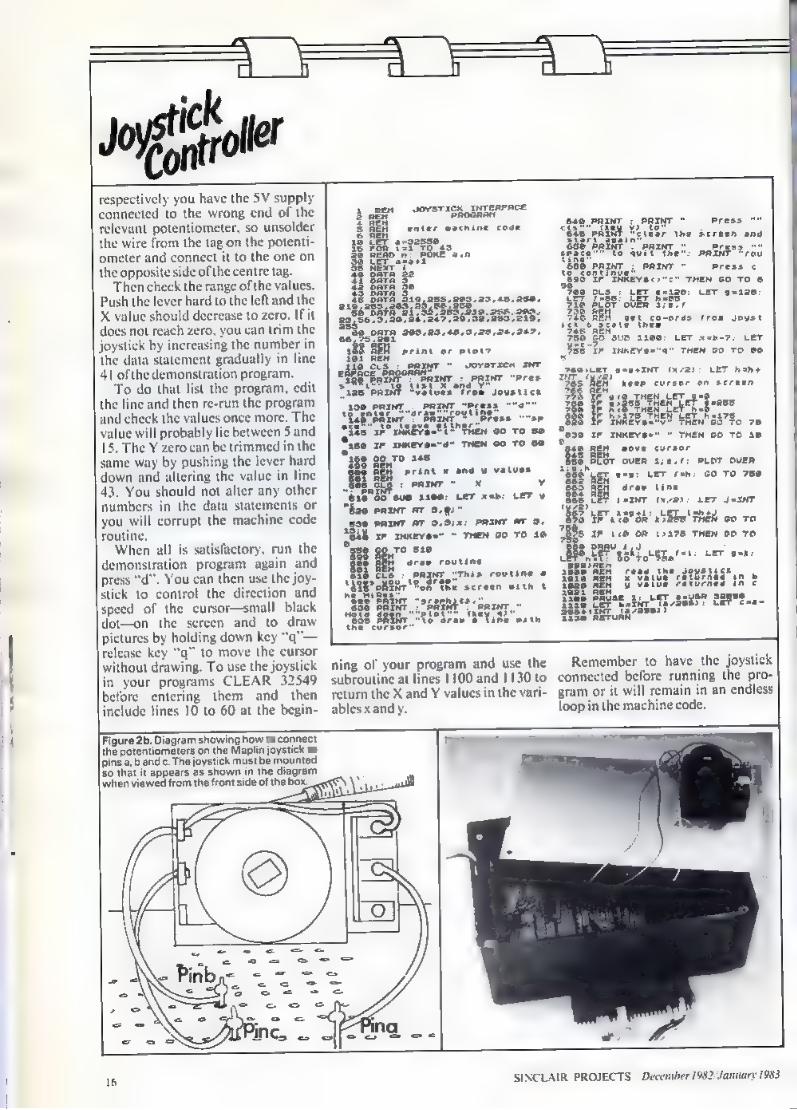
The last step in the wiring isto con- nect the joystick. The sketch in figure 2b shows a view of the joystick as seen from the front of the box and illustrates how to wire the potenti- ometer tags to pins a. b and c on the circuit board—using insulated wire. Ifyou are not using a Maplin joystick you should connect the centre tag of the X-axis potentiometer to pin b, the centre tag of the Y-axis potenti- ometer to pin a, and then connect one of the other terminals on each potentiometer to pin c. The tests detailed will soon show whether those connections are corn
Screw the joystick unit into place on the under-side of the box lid and fit the circuit board into the box, The board may be held in place with a sticky-lixer at each corner but make sure that it touches no metal parts. inally, assemble the box so that the
connector cable emerges from the slot on the lefi-hand side. You are then ready to “fire-up” the interface on your Spectrum,
In testing. setting-up and use, remove the power plug from the Spectrum. fit the edge connector and re-insert the power plug. The Spec- trum should still work exactly as it did previously. If there is any diffi- culty switch-off immediately and disconnect the interface. That should then be checked thoroughly before being re-connected. Assuming all is
That should print a message which switches, apparently at random. between high and low, If it prints only either high or low. you should re-check the circuit board for mistakes or short circuits. Otherwise type CLEAR 32549 (enter) and enter the demonstration program. Save it on tape before you run it
Run the program and press “I” for
well, type and run the following program: 10 REM joystick test 20 LET à- IN255: REM read joy- stick output 301 THENPRINT
HIGH 401Fa=127 THEN PRINT " LOW" 50 POKE23692,255: REM keep scrolling 60 GOTO 20: REM doit again
ofthe X and Y values from the joystick. Move around the lever and watch how the numbers vary Moving the stick from left to right— X-axis—shouldalterthe X value, Iit alters the Y value instead you have the potentiometer connected to the wrong input pins. Return to the circuit board and swap the wires from the joystick to pinsa and b. Ifthe X or Y value becomes smaller when the stick is moved to the right or up
SINCLAIR PROJECTS December 1982 Ми inuary 1983
respectively you have the 5V supply connected to the wrong end of the relevant potentiometer, so unsolder the wire from the tag on the potenti- ometer and connect it to the one on the opposite side ofthe centre tag. Then check the range ofthe values.
Push the lever hard to the left and the X value should decrease to zero. If it does not reach zero, you can trim the joystick by increasing the number in the data statement gradually in line
41 ofthe demonstration program. To do that list the program, edit
the line and then re-run the program and check the values once more. The value will probably lie between 5 and 15. The Y zero can be trimmed in the same way by pushing the lever hard down and altering the value in line 43. You should not alter any other numbers in the data statements or you will corrupt the machine code routine, When all is satisfactory, run the
demonstration program again and press "4". You can then use the joy- stick to control the direction and speed of the cursor—small black dot—on the screen and to draw pictures by holding down key "q"— release key "q" to move the cursor without drawing. To use the joystick in your programs CLEAR 32549 before entering them and then include lines 10 to 60 at the begin-
я JOYSTICK INTERFACE ен rus enter machine code
SREB RE on — i 15 Bare З 18 ВАТА 319, 055.203.23.48,250, 2155255: 203:24288;:256 Bá" Бата 21, 52,289,239. 255.200. 8945543, 20, 26,247, $32,282,219,
do DATA 200,22,40,2,20,24,247, 188 REH print er ptor? 198 Ecs o рахит ` vorsrxen хмт E uad RAE ЖЕК ENIT PRINT: PRINT "Pres Sias paN? 408108597706 Jousticn
Siso zm нквув"а" THEN со TO ве 168 90 то 145 Pp P
SE SES . PRINT” х y 618928 вив 1100: LET хе: LET v "Bae PRINT AT s,e;" gos PRINT AT э,дул: PRINT AT D.
= THEN 00 то за
RINT ; PRINT“ — Press By И MILD Press ii PRIME Frou
Sai HET prago: - Be! БЕТ Roane) DET 97120 BT oUER 1765, H gep co-ords from Joys gett thew dd ^ SUB 2200: LET x=b-7: LET
1uktvs-"a" THEN GO TO ee g&e»LET a9 INT (4/2): LET Ges KER’ keep curser on screen fe ET. Bš SP, e THEN LET gee |l ces we ТҮ mtm 28 BEN 88 BEUT OVER зде, е: PLOT OUER Be uer ems: LET rah: со ro 759 SES ДЕН araw tine БЕ ВЕН Pee Bratman Дана m "M 368 SE LL" Gh SSES TREN co ro j "lbs ar Leo om 19378 THEN op те rum ISI DONNEES
"
ning ої your program and use the subroutine at lines 1100 and 1130 to return the X and Y values in the vari- ables xand y.
Remember to have the joystick connected before running the pro- gram or it will remain in an endless loop in the machine code.
Figure 2b. Diagram showing how to connect the potentiometers on the Maplin joystick to [pins a, b and c. The joystick must be mounted зо that it appears as shown in the diagram when viewed from the front side of the box.
SINCLAIR PROJECTS December 1982 January 1983
=o
ing routines is part of a of text-handling pro-
grams written specially for the ZX range of computers. Word processors
save a great deal of time. They reduce the amount of re-typing necessary to produce a finished piece of writing. More than that, the quality of the product tends to be better than it would be without the processor.
all improvements in the struc- a piece of writing cost a dis-
proportionately large amount of. trouble. Before printing, corrections often have to be made. Spelling and grammatical mistakes need to be rectified. Additions may be needed and unwanted text might have to be removed. À word processor will per- form all those t and offer an
ate opportunity to assess the s of the changes. If you do not
like the new version, it can be edited again,
Word processing facilities could Бе useful in other programs where text output is a feature. The problem is that the word processing programs are very big. They tend to fill the computer. All the space which the program does not occupy is given lo storing the text. If one would like Figure 1
T» COLLECTION of word
Sample verore Formatting
Better text handling on the Spectrum
Word processors save a great deal of time. They reduce the amount of re-typing necessary to produce a finished piece of writing and the quality tends to be better. Randle Hurley, who included a word processor in his recent book of practical uses for the ZX-81 here reveals some guidelines for using the spectrum as a word processor.
to use the benefits of text editing in another program, the two will not fit into the machine at the same time.
The routines listed have been developed to allow Spectrum users to use the essential elements of a word processor, merged with other major programs. The routines are short and use few variables. The whole s у be used ог апу combination can be selected according to preference. The jobs which the routines cover are Figure2
ng the margins, avoiding the splitting of words across two lines, and storing the text in some conven- ient form for editing. Some people find the appearance
of right-justified text rather un- natural, while others much prefer it to a ragged right-hand margin. How- ever you prefer your margins, some things cannot be tolerated. Lines must not start with spaces unless there is good reason and punctuation marks must appear at the start of lines only if they are preceded by a space in the text. All the text pro- duced by the routines will be left- justified cording to these rules. Right-hand justification can be switched-on by setting a fat, rj, from 0 to 1. The formatting routine will put its output on to the
screen. It isa matter of conver the PRINT statements are accom- panied by LPRINT statements or ifa
eenful of text is allowed to build, to be copied and then cleared away for the next block. ures one, two and three show the different forma
Figure four shows the first of the routines which carries out the formatting. The by-pass at line І sends the computer to the main art of the program. The routine is
called into play by a GOSUB call. You will have to replace line 28 with asimple RETURN statement
The routine is allowed to stop at line 28 when the whole of a $ has been formatted and printed. Thi convenient for testing the ope ofthe routine buta RETURN needed in the working version. There is a REM statement at line 29 to remind you that the flag needs to be set before the routine is called.
The next part of the set trims the text as it is entered, This word wrap- ping makes it easier to check the material on the screen and to visual- ise the final appearance of the text. Figure five shows the effect of the routine on a partly-filled screen. The word routine normally would split at. the end of the line but the computer moves the word to the next line to Бе finished.
The word wrap facility in figure six is part of the main text entry routine, The keyboard is live while the rou- tine is working and that means that the keyboard click is lost. To some people the click is valuable feedback, while others find it intensely annoy- ing, Those who would prefer not to hear the click should delete the BEEP .005,0 from line 13. When trying the routine it is convenient to stay inside the loop but when using the routine in earnest, the STOP command Figure
Arter justifying both margins
SINCLAIR PROJECTS December 1982/January 1983
Figure4
routines 2 3 j=1 $ SE LÉN b
RINT b$: RETURI Б IF b$(j)
сто LET у=у+1:
во ore З GO TO 4 LET пс=1 LET len=33
IF b$(1)-" GQ TO 23
п=1еп-2: 26 60 sup 2 27 LET nc=n 28 PRINT a4
RN to an appr main program
B9 REM rst n fight hand
* t ас Pri
е u.
є < °
h jus
Formatting routines 1 GO TO 100: REM Bu-Pass the
LET b$zb$( TO ten-i)
32 OR rj=@ THEN P
Ji*b$(t) TO 2: iR StEN BS нем
IF nc+ten>LEN a$ THEN GO ТО
LET b$-a$í(nc TO nc«ten?
аб IF b$ilen)co" " GO TO эз
п: Ti a
1 i
THEN ex sam bs LET
THEN LET nc=nc
THEN LET le
GO TO 21 25: REM RETU Part or the
°
° switch о
te
ag t fication
should move the machine back to the main program. To allow that to happen, convert
the REM statement at line 51 to ЧЕ
allow you to escape from the routine. While entering text, mistakes can be removed by means of the normal DELETE procedure, shift 0. This facilit: intended only for minor correction. Major alterations to the text should be done while editing. The editing routine might be used
alone, to edit text from another source. The keyboard reading rou- tine has been repeated because of the possibility. As written, the routine will allow the editing of the first 704 characters in a S. If a 5 is shorter, а check will prevent the need for the userto edit non-existent material.
To edit the text beyond the first.
page, the variables a and b will have to be altered to point, respectively, to the first and last characters to be printed.
The paging routine will vary con- siderably from one program to the next, so that section has been left for the user to design according to the dictates ofthe task.
The normal cursor control Кі to 8, allow the user to point to any
[character to be removed, or one
ahead of the point at which new text will be added. Press the e key and then choose one of the options. If INSERT is selected, the Spectrum will ask for the new material. Enter it at the bottom of the screen and it will be inserted as soon as the ENTER key is pressed. Figure 6
Figure 5
When DELETING, the computer needs to know the number of haracters to be removed. When this
is keyed, ENTER will remove the unwanted characters, Again, the routine has been written to be tested. An escape is needed in the working version or the user will be locked into the loop. The REM at line 80 is to remind the programmer to insert а RETURN statement to be executed when a suitable signal is given. The
shif/a—which was used in the text entering routines could be used again, The results can be seen in. figures seven and eight.
The excellent ZX Basic string- dling facilities have been used to
perform the editing work. The Spec- trum will allow very long strings to build and string-slicing works very
GO sup 210:
43 PRINT AT 23692,9: LET c
: LET а=а+1
45 GO TO 42 46 GO SUB 10-
N GO TO 41 48 IF SCREENS
EN LET с=є- 49 FOR j
j-C; SCREENS g3;" =: NEXT d: T' Br 22,с-2;ь8: 1, ate CODE bs
: LET a$-a$( TÓ
c TO
52 GO TO 44
cope b$:126 THEN GO ТО
сї
44 IF c=32 THEN GO TO 46
CODE ЬФ>126 THEN GO ТО 59 47 LET a$=a$+b$:
GU ТО ¿E
20, j): EET C
PRINT AT 21,c;
БІ ВЕН If CODE Bee 226 (shi гүр far STOP) THEN RETURN
NT. IF CODE bé<S2 OR
.€ib&;" ": POKE LET a$-a$sb$
IF CODE b$<32 OR
- НЕ
ти
PRINT AT 21, PRINT AT 20,
с+1: PRIN GD To 42 2 THEN LET c=c-
г LET а=а-1
IF Ь%=
t(29,c-1) cs" "
за:
a=
18 SINCLAIR PROJECTS December 1982/January 1983
quickly, giving virtually instantan- allow the production of hard copy. cous, on-screen editing. Figure nine If each PRINT statement
ompanied by possible. POKE may prove beneficial as well.
s full the Spectrum
is the code which makes editing
The routines are brought into pl When the screen be means of GOSUB calls from the | Figure9.
normally asks if it should SCROLL. POKE 23692,9 in the line containing the PRINT statement allows the вше?
жнт
computer to SCROLL whenever it needs to do so and removes the necessity for pressing a key whenever the screen fills, There is an example for you to follow in line 43 ofthe text entering routine. Variables a
j general counter rj rtjustification flat len line length пе nextcharacter number Text storage and word wrap variables € columnnumberofcharacter d characternumberina$ Editing variables à firstcharacterin block b Іазі character in block F cursorcolumn.
main program. To start writinga new piece of text, call GOSUB 40. If an
dition to the existing material is needed. the following commands should be given—PRINT AT 21.0: followed by GOSUB 42. Whichever call is made, the escape from the
writing loop is made by keying shift/a.
Editing the first page of the writing is achieved by the call GOSUB 60. If other parts of the text need to be treated, the variablea should be set to the first character and b should be set to the last. GOSUB 62 allows editing of the specified text but be careful to specify only а sereenful—704 characters—at a time. Again shift/a allows an escape to the main program When formatting the text for print-
ing, set the right-hand margin flat rj. to zero for left justification or to | for justification of both margins. This routine needs the addition of LPRINT or COPY statements to
The editing routine IF INKEY$<> IF INKEY$-"" THEN GÖ ТО 11 LET BS-INKEYs: IF b$ To BEEP .005,0: RETURN LET c21: LET
IF b»704 THEN LET PRINT AT O,0;a$(a TO
Ness GO TO 63: REM Or somewhere sens
азежзаєі: IF b$="d
THEN GO TO 10 = THE
e-10: LET ree:
fi OVER 1;'.— PRINT BT ë T; ov
THEN LET’ РЕР
delete“; b AND b$c»"d" THEN
THE new material"; bs TO а)+Ь%+а%(а+1 many characters? TO a)+as(a+e+1 T
SINCLAIR PROJECTS December 1982 January 1983
== =
ATCH-CARD is an casily- I built, low-cost 8-bit output
memory-mapped latch at 5 36850 fora 81 which can
be modified for the Spectrum. The bits of the latch. may be set and
у POKES. The latch. . will always return
regardless of the value POKEd. It enables the Z. 1 or Spectrum
todrive the Power-Card project. Construction of the Latch-Card is
different from other m: пе pro- ed-up on Vero-
rd so that you can build it easily Without having to send for a spei printed circuit board or having to etch your own.
The Veroboard used is made specially for integrated circuits and has the tracks already broken every four holes. You can buy it in pieces 5.85in. x 2.9in. and you will need to cut off а piece 3'4in. long—figure two.
To e sure the board is wired properly it is best to follow a wiring schedule. All the pins on the same row of the wiring schedule should be connected together.
Start construction by soldering-in the edge connector, leaving ‘in, between the body of the connector and the Veroboard—figure one. If you wish to use the Latch-Card with other add-ons then, after soldering the edge connector gently, bend the pins towards each other and insert the extender card, making sure that the slot in the card is behind the blanked-off slot in the edge connec- tor; then solder the pins to the tracks on the extender card.
Driving force at a reasonable price
Dave Buckley details how to make a Latch-Card which is wired-up on Veroboard so that it can be built easily without having to send for a special printed circuit board or to have one specially etched. It is an easily-built, eight-bit, output memory-mapped latch at address 36850 for a ZX-81 which can be modifiedfor the Spectrum.
Then solder-in the IC sockets. One 16-pin socket is for the output. The 20-pin socket is for the 741.537. The other 16-рїп socket is for the 741.5133 and the 14-pin socket is for the 74LS04—see figure two for correct location of the sockets. Solder-in the capacitor and the diode. making sure the diode is the proper way round; the end with the band should be towards the edge connector.
Then you have to use the wiring schedule mentioned earlier. It does not matter how you route the wires so long as they do not go over the top of Figure 1
The extender card is available from Technomatic The edge connector is available from adver- tisers specialising іп 2Х-81 parts. The remainder should be available from any good component shop.
COST
Vero VQ board Edge connector ZX-81 O. 1uF capacitor KB914 diode 1K resistor 7415133 7415373 DIL 14-pin socket DIL 16-pin socket (at 12р) DIL20-pin socket Extender card Connecting wire оооор-ооооы- съв OOOD S538-s589985
3 | B
20 SINCLAIR PROJECTS December 1082 January 1983
[АТН CARD
` \ VM NS ——— М aa
Figure 2
COMPUTER
the IC sockets—see photograph for a guide. Start by wiring the 9V pin on the edge connector to pin 10 of the output socket; then the 5V pin on the edge connector to pin 16 of the socket for the 74LS133. Connect that pin to pin 14 of the socket for the 741504, then connect it to pin 20 of the socket for the 7415373 and finally that pin to pin9 of the output socket.
Then do the same for the OV pins of the edge connector to the other
ins in the same row in the wiring schedule, followed by D7, DO and so on.
The best way to do the wiring is to strip ‘hein, off one end of the coil of connecting wire, solder it into the Veroboard at the start connection, lay it roughly over the board along where it will be finally and cut it off Vain, past the finish connection strip ‘asin. from the end and solder it in. When all the wires have been solde: ed, they can be pressed and squeezed with the fingers to lay in reasonably neat runs, The resistor is then solder- ed on the back of the board direct pins 20 and 11 ofthe 20-pin socket. When all that wiring is finished,
check the copper side of the board thoroughly for solder splashes, bridged tracks, dry joints and other examples of poor workmanship, and clip off any wires protruding more than Visin—figure three.
Then insert the integrated circuits, making sure you have them the correct way—figure two. You may need to squeeze the pins together gently to be able to fit them into the sockets.
If you are sure everything is correct, unplug the power supply from the ZX-81 plug in the Latch- Card and return the power supply to the ZX-81. The K cursor should still be there and everything should work normally. If it does not, unplug the power supply, unplug the Latch- Card and check each connection for bridged tracks and dry joints.
If you find anything wrong you must have put the wrong wire in the wrong hole; it is very unlikely that the ICs are faulty. Take the chip: from the sockets and, with a multi- meter set to ohms, check that you
LAIR PROJECTS December 1982January 1983
have followed the wiring schedule correctly.
The Latch-Card occupies 32 memory locations from 36 x 1.024 - 32 (or 3682) to 36 x 1.024 - 1 (or 36863) and POKEing any one of them will have the same effect. An easy address to remember is 36850. To set all the bits of the latch to logic 0=0V POKE 36850,0.
To set bits of the latch to logic | = 5V see table опе for the value to be POKEd.
The outputs of the 74LS373 can source 10 in mA and so can drive the
ie of driver transistors directly, e.g. those in the Power-Card.
If you have a 16K Spectrum and wish to have a memory-mapped out- put latch set by POKEs, the only modifications necessary are to use a longer 2 x 28-way double-sided edge connector, leave off the diode and follow the edge connector signal locations for a Spectrum. An exten- der card will be more difficult to obtain fora Spectrum.
If you have a 48K Sp wish to have the Latch-
mapped set by Basic OUTS. you will have to follow the Spectrum wiring schedule for the 1/O-mapped version. The I/O address in that case is not so easily worked-out as for the ZX-81, since any I/O address must have the AO to АЗ address line as logic 1 or the Spectrum does some- thing you may not want. Table two gives a list of I/O locations occupied by the Spectrum Latch-Card as wired according to the Spectrum wiring schedule,
You will note that the diode is omitted from the Spectrum wiring schedule; it is not needed, since it is not necessary to disable a copy of the ROM as one has to do on the ZX-81. Neither is the associated resistor needed.
Table 1
TRELE &
Spectrum Latch-card i dares зва: +58 ii 238: 1 +38; i хз: i э i #3,
#3: is
33993949999999999999939999999999 TRERRRRRERATARRRRARRIARRRRR AAA Ù собоююбюовобосорСесронофівавоюоо Ob ношачолесюном о 0 GIU x. TTS 9565666605655959569665655655506566 ОПОРОЮ ТОГО TOTO ODIO JO TUTO В ПОТОКОВОГО SRERREERERERRRRRRRRPARPPRRRERERE
Toset POKE36850
Bito 1 1 2 2 4 3 8 4 16 5 32 6 64 7 128
To set апу combination of bits, add the corresponding values, eg, to set bits 2and$.
POKE 36850, (4-32) or OUT 7999, (4 «32) for Spectrum 1/0 version.
Edgeconnector 7415133 741504 7418373 Socket | „ә 7415133 741504 7415373 Socket H Diode ov 8 3 110 — 11-16
9v 10 Ра 18 Bv 16 14 20 9 B» З D 18 D 7 Do 8 ES А Ë 9 Ds 17 D; 4 Ds 14 Ds 17 ві 8 Ds 14 be 13 3 19 1 Es їз 18 2
na d 15 3 1s 5 12 4 15 з š $ 12 3 8 7 3 8 4 p 6 З 2 5 5 £ дм n" 3 5 An 9
TOREO 5 Aw 1 WR 3 An z з 1 Aio 10 Ан n 12 W An 9 9 15 An 6 В An 7 1 4 Avo 10 H 8 А 11 5 8 Аз 12 4 10 А 13 дә А 14 ^ Ao 15 =
As Fog - 3 2 МЕЕ 5
5 8 $ Ts 9v 10 12 T 5v 16 14 20 9
l 1 1% 8 7 110 11-16 Figure 5
7415 133 s D7
s DÓ
as DS
su 04
so D3
saa 02
ее DI
ssa DO
SINCLAIR PROJECTS December 1982 January 1983
А k = Y
Brightening the festive season
Dave Buckley details how to improve your Christmas tree decorations by making a simple power card which will allow your ZX-81 to control the switching on and off of the tree lights. The card can also be used for a number of other switching applications, including lamps, aquarium heaters and model railway points.
HIS IS a simple, low-cost pro- heaters orelectric fires. If you build it I ject to permit you to switch оп іп time, you can dazzle and amaze
and off under program control your friends and neighbours by using up to four 5 amp loads at upto mains your ZX-81 or Spectrum to control voltages, although because of the your Christmas tree lights. Used with limitations oftheconnectorsusedthe an add-on sound board. you could total of the four loads should not even have your lights flash in time exceed 5 amps. with music. h as Christmas
The Power-Card is controlled via carols. any user output port such as the You will see that the circuit board Latch-Card. |t is designed to be has been mounted in a stout plastic plugged straight into the Latch-Card. Verobox; that is essential if the A
Suitable applications for the Power-Card include switching lamps, aquarium heaters, electric motors and model railway points.
Power-Card is to be used to switch mains voltages. On the other hand. if you are to use it only to control your model trains, the box can be omitted
The warning is that it should пої Бе and the cost of the project will be used to switch unattended room almosthalved.
Rly . Riy4 Maplin (10 amp mains relay—VX97F} BC107B transistors— 1Kohm resistor—R..... Ra 1N914 diode—D, ... Dš 100m 16V capacitor—C GBA solder tag 12-way connector block (5 amp rating) 7-way connector block (5 amp rating) Vero case 202-21037L type 214 180mm. x 120mm, x 40mm. con- necting wire
All the components can be obtained from Maplin. To connect the Power-Card to a user port.
you need either two 16-pin dual in-line header plugs and one 1ft. 16-way ribbon cable or one 16-pin DIL plug to 16-pin plug cable assembly. The header plugs and ribbon cable should be available from any good component shop.
The case assembly is available from Technomatic and other computer compon- ent shops.
T
==»
24 SINCLAIR PROJECTS December 1082 January 1083
E
"ard is built on a stan- dard-sized piece of Veroboard. Insert the big components in the cor- rect place in the Veroboard using the component overlay diagram—figure опе—аз a guide, and solder them in place. Then work your way down to the small components: it is easier to have the locations correct that ма; When all the components have
been soldered in place and the exce: leads have been cropped-off, Vein. twist drill held in your fingers or a Vero trackbreaker to cut the tracks in the places indicated. Although this is the opposite of constructing things from that usually recommended, if the tracks are cut before fitting there is great difficulty in finding the correct locations.
Having fitted all the components, mount the 12-way connector block using two 6BA nuts and bolts or stick it down using sticky pads. When it is in place, use thick insulated wire to put in the links between the connec- tor block and the relays. Use blue for the common connectors, yellow for the normally-closed ones and white forthe normally-open connection on each relay.
a
Figure 2: Power-card schematic. '
Ri і |
T7 a3 E С
=, alli о
лг 5555650606 Ж! ЫЛ
'
?9 0009,
SINCLAIR PROJECTS December 1982 January 1983
$
с Б Where the links enter the Vero-
board, make sure that there is a good solder connection between the link and the relay connection. For the normally-open connection (white) lay an offeut of component wire along the Verotrack between the white link and the relay connection and solder it in place to give a good, thick connection. Vero-tracks by themselves will burn-out if you try to put 5amps through them.
The Power-Card uses only the lowest four bits of the output latch and so you can use the upper four bits to control something else. If the unused upper four bits is routed along with the9V, 5V and OV linesto SK2, you can plug-in something else there—perhaps another Power-
]—but in that case it would be advisable to route the unused upper
Figure S: Model motor control
Motoron/offusing one relay
Step Y—— 90
3961, alls
four bits to the lower four bit posi- tions of SK2 and then the second Power-Card should be identical to the first: otherwise on the second card the four base resistors would need to go to bits 3 to 7, rather than bits0 to 3.
Ifyou do not want to use the upper four bits, you can omit SK2 and its
interconnecting wires. One point you may notice—SK1 and SK? are one way round in the photograph and the other way round on the drawings.
Figure 6
motor forward/reverse using one relay
forord
etse.
The drawings are correct, Having sembled all the circuit board, there
must be some way of holding it in the. A piece ої З/віп. balsa, lin. x
Sin.. can be stuck, using sticky pads, 1o the Veroboard under the con- nector block, That gives support for when you are connecting wires to the Power-Card. Also you could stick Ма x lin. pieces of З/віп. balsa underneath SKI and SK2 to give them some support, again using sticky pads,
If you are to use the Power-Card to switch only low voltages you can leave itat that but for mains the box is needed, with the balsa feet stuck to the inside ofthe box.
Using more sticky pads, stick in the 7-way connector block. File five hein. slots in. deep in the back panel and make sure they are smooth
Figure 3: Back or Veroboard
hit 5
o
5
о
Relay power connections
Yellow
verotack thickened with wite опа! sock
26 SINCLAIR PROJECTS December 1982 January 1983
à ў
Figure 7
motor forward/reverse/stop using two relays
ает р к очо
| Relay 2 X
and then attach a solder tag with a 6BA nut and bolt. Then cut a slot in the left-hand side ofthe top ofthe box (by SK1) for the input to SKI—sec figure six.
The box wiring is shown in figure seven and it should be done in thick wire whieh will carry 5 amps. Then the mains supply wires can be wired into the three connectors marked Mains In, Earth, Li nd Neutral. The four li can each be wired between one of the neutral out con- nectors and one of the four NO— normally | open—connectors Бу
s. To prevent putting any strain on
the connectors by the wires leaving the box through the slots in the back panel, tie a knot in each lead before
i s through the slot —see figure eight—making sure that there
is slack on the inside of the box. Nothing could be easier to operate.
Attach the 16-pin DIL jumper cable between SKI and the Latch-Card or some other 8-bit output port, making sure that the orientation of the plugs is correct. If some other 8-bit output port is u: you must make sure that the various signals and power lines have been transposed to suit SK 1.
Writing zero to the port will turn- offall the loads and writing a 1 to any of the low-order data bits will turn-on that particular rela: . POKE the
port with 1 will turn on relay І POKE with 2 will turn on relay 2, POKE with 3 and both relay 1 and relay2 will be turned-on.
The Power-Card will control small DC model motors easily but when that is being done the Power-Card must not be connected to the mains. Figure 10 gives details. Here is a sample program to drive
Power-Card using a ZX-81 and the Latch-Card: 10 REM ASSIGN ADDRESS TOP. 20 LET P=36850 30REM ASSIGN MAXIMUM PAUSETIMETOT 40 LET T=100 50 REM RANDOMLY SWITCH EACH RELAY 60 REM AT RANDOM TIMES 70 РОКЕР, RND*15 80 PAUSE I T*RND 90 GOTO 70
PORT
Figure
Alternative method motor forward, Tcverse/stop using two relays
EAT Figure 9: SK1 pin allocation
Ov Ov Ov
Figure 10:
5v
Dó D5 ра
SK2 pinallocation
notconnecte but see text
. slot for signals to
SKL
SINCLAIR PROJECTS December 1982/January 1983
ee L AR — ues =
28 SINCLAIR PROJECTS December [082 January 1983
— 0 £
зб ç 1 ý
Dn SINCLAIR 2x81
л
Figure phics generator board attached to the
Circuit training helps to build good characters
HE CHARACTER table—dot lerns—are located in the
X-81 ROM from 1Е00 (hex), lo IFFF (Бех), i 7680 to 8191 decin h character requires eight — bytes consecutive addresses—to define the dot pattern forthe shape required, as shown:
Good graphics can make all the difference to a program.
Dave Looker investigates ways of defining your own illustrations.
articular bit isa ̀l”, the corres- tion will be black: if the
bit is "0 the location will be whit The circuit described will enable
the character table area of the ROM to be replaced by RAM. which will enable the user to define his own characters by POKEing the required bit patterns into the relevant memory locations. To accommodate the
dot-pattern table, a minimum of
bytes of RAM will be required, It would be possible, of course, to build the necessary RAM ICs into the logic circuit board but that is not really necessary. When any 16K RAM extension
module is connected to the ZX-81, the original 1K of RAM is disabled by connecting the internal RAMCS
PARTS LIST Components required for this project are: 2 741500 Quad NAND gate ICs 1 741508 Quad AND gate IC 1 10K AW resistor 1 SPST miniature toggle switch 1 smallpieceof Veroboard 1 metre of single-core insulated wire. Total cost approximately £2 GLOSSARY RAMCS—RAM Chip Select—the line above means active low. ROMCS—ROM Chip Select—the line above means active low.
SINCLAIR PROJECTS December 1982 January 1983
pari TOR
бре line to +5У. That means that these RAM ICs are available for use as our Characters RAM, with some modifi- cations to the connections, as detailed.
Since the ROM character table is addressed by the Sinclair logic 1С during the Display Refresh Interrupt section of the machine and not by the Z-80 processor, it will be necessary to modify the address con- nections to the RAM ICs,
Remove the 2114 RAM ICs from their sockets, taking note of the posi- tion of the identifying notch in the en lofeach IC,
а pair of tweezers, bend the adis pins A0 to A8—pins 2, 3, 4, 5,6,7, 15, 16 and 17—upwards until they are at right angles to the rest of the pins.
Re-insert the ICs, ensuring that they are orientated correctly, as shown by the identifying notches.
Using fine insulated single-core wire anda fine-tipped soldering iron, link the corresponding pins of the two ICs Кр g.. pin 2 to pin 2, pin3topin3
Using the same fine wire, connect the address pins of the two RAM ICs
to the address pins AO to A8 of the ROM, as follows: RAMICpins ROMICpin Address line.
It is not necessary to re-connect the A9 terminals of the RAM ICs (pin 1) to the ROM A9 terminal,since this is a direct connection already.
Having constructed the CHRS. logic circuit on Veroboard as shown in the diagram, proceed with the con-
і li line must be located
—pin 23B of ZX-81 edge connector —and CUT at a convenient point between the edge connector and the OM. ‘A small, sharp screwdriver can be
used to cut the printed circuit tra The RAMCS line must be loca
—pin 2A of edge connector—and cul at a convenient point betwen the edge connector and internal. RAM ICs.
The ROMCS line—pin 23B of
edge connector—must be connected to the ROMCS input of the СНВ$
S output from the CHRS logic circuit must be connect- ed to the ROM ROMCS terminal— pin20ofthe ROM IC. _
The CHR$ RAMCS output from the CHRS logic circuit must be con- nected to the internal RAM RAMCS terminals—pin 8 ofeither RAM ІС,
The address lines A9, A10, А11, A12 and A13 must be connected to the CHRS logic circuit as shown in the diagram. See edge connector diagram for location of'address lines.
The 45V and 0V connections to the CHRS logic circuit must be con- nected to pins ІВ and 4B of the edge connector respectively.
The switch (51) connections from rcuit must be con-
nected to the miniature toggle switch, which can be fitted in the rear of the ZX-81 case, above the circuit board.
All leads should be kept as short as conveniently possible; the CHRS logic circuit board can be located,
adh
ROMCS
(то ROM)
CHR$ RAMCS (TO CHR$ RAM)
30 SINCLAIR PROJECTS. December 1982 January 1983
В ЕЕ IS
А Таке great саге with all соппес-
lions to avoid shorts between circuit ; in particular, connections to
the pins of ICs should be made as quickly as possible: do not heat the pin for more than two or three seconds at a time, otherwise damage
ZX-81 will no longer work without it.
Switch on the power to the ZX-81. If the cursor fails to appear within the usual time, or the display goes into a crash state, switch-off immedi- ately and re-check all the connec-
iure Віпагусоде | Hexcode Decimal 10111101 BD 189 01111110 7E 126 11011011 DB 219 11111111 FF 255 11100111 E7 231 01111110 7Е 126 01000010 42 66 10000001 81 129
to the IC тау occur because оГ tions. It is unlikely that any perman- 'essive heat,
Check that all connections are correct and that no shorts are present: if everything seems satisfactory you are ready for the initial test of the circuit, as follows:
Make sure that the switch SI is open, i.e., in the normal position. The purpose of this instruction will become apparent later.
Connect your ZX-81 to the TV set and power supply in the usual plug-in the 16K RAM pack.
ent damage could be
aving locat- ed and corrected any errors in the wiring, the circuit should then work correctly When the cursor appears, enter а
few commands or letters to make sure that the keyboard is working correct- ly, then switch SI to the CHRS posi- tion—i.e., close S1.
The screen display should change immediately to a random high- resolution pattern, with any charac-
lers becoming blobs.
The reason for this effect is that the memory locations in the 2114 static RAM ICs assume random values at power-up; when 51 is closed, the ROM CHRS table is replaced by the
randomly-shaped
CHR$ RAM which, at present, contains random data, hence the screen display will be random garbage. When SI is opened, i switched back to the normal posi- tion, the display will revert to normal.
Having completed the initial test, re-assemble the ZX-81 and proceed to the initialisation routine in the next section.
r circuit operation and initi ation, with SI open, the 'ANDED" combination of A9. A10, A11 and A12 will enable RAMCS fro to 16383 (decimal), with M enabled from 0 to 8191 (0-8K); A13 is used to disable the ROM from 8K to 16K. Thus the computer will operate normally, using the charac- ter table in the ROM, which can then be copied ino the CHRS RAM—15872 to 16383—either by using a machine-code block-shift
I re 4: Memory map i
<
ROM 1 L i
7680 8K Y 15872 ЖК
ROMCS t apy SI 1 ТИТ OPEN D ГЛ ()
CHRESRAMCS ! ЛД ' ' '
| ui FI ROMCS ] ! і
SI à : ' CLOSED, : ^
CHR$ RAMCS , 1 I ' 1 І £ 4 ! 1 1 єл
“SPARE T “T NORMAL 1 1 RAM
SINCLAIR PROJECTS December 1982/January 1983 31
routine, or by entering a Basic pro- gram (а) of the form: | FAS
20POKE A, PEEK M 30LETA-A-«I 40NEXTM S0SLOW
This program copies all the CHRS dot patterns in the ROM character table into the CHRS RAM position- edat 15872 to 16383 on the memory map—3E00 to 3FFF hex. Once run, it can be deleted by the
since NEW will not the CHRS RAM. ith 51 closed. the ROM will be
abled from 7680 to 8191 and the CHRS RAM will be activated in its place. The CHRS RAM will also appear at 15872 to 16383 on W memory map, since CHR$ RAMCS will be active-low in this region also.
Having loaded the ROM dot patterns into CHRS RAM—using program (a)—closing 51 will have no effect on the display but the user can then change any ofthe characters by POKEing the required values into
the relevant memory locations. The character table can be poked in either the 7680 to 8191 section or the 15872 to 16383 section, since the CHRS RAM appears at both loca- lions when SI isclosed.
The most straightforward way of defining your new character is, fi draw your desired character—prefer ably on graph paper and write Ше binary code corresponding to
ch line, as shown in the example— igure three.
Having worked-out the required a „ ап easy method of con-
can be employ- ed, using this table: Binary Hex 0000 O Divide the 8-bit code into two 0001 1 4r-bit sections and look up 0010 2 atthe hex code for each half in 0011 3 the table. The hex equivalent 0100 4 of the 8-bi code is the 0101 5 combination of the hex codes 0110 6 forthetwohalves: 0111 7 eg. 1011 1101 1000 8 B D 1001 9 1010 А So 10111101-BDhex 1011 B 1100 С Using this method, the 1101 D codes for each of the eight 1110 Е bytes which define the 1111 F character can be derived as
shown for Invaders example
the Space
Figure 5: Bend pins 2-7, 15-17 and re-insert ICs into sockets Figure 6: Solder wires between ber
SINCLAIR PROJECTS December 1982 January 1083
quati The next step is to decide which
existing characteris to be replaced by the new user-defined character. The character code for the character to be re-defined can then be found in appendix A of the manual. That will be a number between 0 and 63, since the inverse characters are generated automatic- ally by the ROM and will always be the inverse of the characters 0 to 63. The obvious first choices for
characters to be re-defined are the graphics characters—codes | to 10—since they will not affect any text content of your program. The follow- ing program (b) can be used to re- define any characte 10 Print “Input
63)" 20 Input e 30 Print C 40 Print "Input new character Hex Codes" 50 LetM=15872+C*8 6OForN=llo8 70 Input HS SOPoke M, 16 “code HS (1-28) + (Code HS (2)-28) 90 Printat 21,01 M: "=": HS 100 Let М=М+1 110 Scroll 120 Next N
For example, input “1° in response to the request for a character code
er code (0 to
and then input the hex codes for the space invader. To test the result, print the graphics ‘I’ character to the screen in the normal way, then close 51. The graphics "І will change istantly to the space invader. The NEW command will not
affect your new characters, since the
1 Fas 2 Dim AS(10, 16) 3 Let AS (1) - "BD 7E DB FF E7
ivaderexample) haracter hex codes"
7 Let AS(5) s "Character hex cod 8 Let AS (6) "Character hex codes 9 Let AS(7)= "Character hex code: 10 Let AS(B)— "Character hex codes 11 Let ASQ) 12 Let AS(IO] 13 Le Az 15872 14 ForM- 7680 t08191 15 Poke А, peck M l6Lel Az Asl 17 Next M 18 ForC=lto 10 19 Let Me 158724 C*8 20 ForNz По 15 сі 21 Let HS=AS(C, NtoN+1) 2 Poke М. 16 *(code HS (1-28) +
(code HS (2)-28) 23 LetM=M+1 24 Next N 2: 26 Slow l
racter hex codes haracter hex codes’
CHRS RAM is located below 16K. (16384), which is the start location of the normal RAM area.
Unfortunately, that also means that the SAVE command will not save your characters either. To save the new characters on to cassette, it will be necessary to find a way ої storing the dot-pattern data in the normal program area of RAM.
The easiest way to do so is to store the data in the form of a string—or strings—together with a routine to load the data into the CHR$ RAM before the main program is run. A suitable program (c) would take the following form—see figure nine.
This can be used as a characters initialisation routine at the start of any program in which user-defined graphics are to be used, since it incor- porates program (a)—lines 13 to 1/—1o copy the normal character set into CHR$ RAM before re-defining characters 1 to 10. In fast mode, this routine takes approximately 10 seconds to execute—a small price to pay for the flexibility which is afford- edby user-defined graphics.
Figure 7: Connect board to main PCB Figure 8: Attach switch to rear o X-81 case
SINCLAIR PROJECTS December 1982/January 1983
aes а аі
ЕРКОМ blower needs large software element
ECAUSE most users of the ZX- 81 are software-orientated, the
in this design. The software needed to run it consequently will be large and some of it із in machine code.
The heart of the design is the 8255 programmable peripheral interface device. This chip 24 lines of input or output, which can be defined by software. There are only sufficient to handle the 2 EPROM. Port Is used to output and read the data, port B to output. the eight least significant bits and port C for the remaining address bits and control bits. Table one shows which functions port C has for cach of the two types of EPROM. The design caters for the 2516 and 2532
Stephen Churchman details how to expand the storage available for programs using inexpensive components.
EPROMs from Texas Instruments, The 50ms programming pulse is timed by the hardware and PC4 out- put must return to 0 before 50ms has gone by.
A simple program is included to enable the programming of the EPROM. The machine code routine in the first REM statement will pro- gram one memory location and read that memory location. The Basic will
s required, The de is required is chip is placed in
the 1/О map of the 7-80 so that the memory map із left alone. In the ZX-81 the PEEK and POKE com- mands access only the memory map. As Sinclair has not fully decoded the 1/0 map it was difficult finding somewhere where the 8255 was not affected Бу t X-81,
Another reason for leaving the memory map alone is so that EPROMS can be placed above the 8K ROM, These could contain routines to improve the 8K Basic. nyone building it is also advised to
acquire a data sheet on the 825 the chip is very complex.
Referring to the circuit diagrams,
Figure 1:
240v
|y o
BD235
9 gu:
22004f—3
+
SINCLAIR PROJECTS Decemberl983January 1983
Figure 2: EPROM blower outside its case і Fis S.U. diagram.
| 5: 8255 reset | 'O s, q n35 l 5K6 13 pins
74123 clr 12| р 79 pin 3
ЗАН! 8 75 ZX8/ үе CONNECTOR
1 Aoo——ÀÀ5s 6
Aio—L 4j & 1 } 3 1
І ; 2 13 " І gem г — a — 3 i| (1 | ] es
A l | & — 4 | 9 рїп 6
| A70 1
I = ова ! $255 VOaktesdecoser
SINCLAIR PROJECTS December 1982/January 1983 35
two Nand gates have been used and three Or gates to drive the chip select pin. CS will go low only when A0. AT. A2, АЗ are logic | and A7, ОКО are logic 0. That places the 8255 at ТЕН, ЗЕН, SFH, and 7FH. The other
9V windings in series aiding. The 50ms timer uses а 74123 TTL chip—only one half is being used. The diode And gate is needed as pin
The prototype is constructed on two pieces of Veroboard; the PSU on 0.15їп. matrix and the main com- ponents on a piece of VQ board. It is
20 of a 2: reading (C5) and low for 50ms when
wired with Verowire, which is ideal for a prototype, as modifications are
needs to be low when
two Nand gates ensure that the 8255 programming. casy to implement. The final board is ms timer are re-set when тенет isapplied.
The only difference between the 2516,2K by 8-bit 2516 and 2532 EPROMs are two EPROM function — Nothing Read Program pinsand t at is why a switch has been PCO АВ —Standard Address. Inputs—
included. When programming the РСТ А9 —Standard Address Inputs—
2532. the programming voltage must PC2 A10 — Standard Address Inputs—
be switched from 5V to26V andback | pcs пераа i i к= to SV either side ofthe programming | pcs кан сх w ad pulse. With the 2516 it may beleftat | Pce cs High Low High 26V to verify the EPROM contents. PC7 5v/26v High High Low
The 26V regulator can be switched to SV by the PC7 output going high. 2352, 4K by 8-bit Switching-on the BC108 and placing ANN пр e nm a 5V zener across the 24V zener. [zs fA “Быз диня
The power supply is standard, PC1 A9 —Standard Address
using a single transformer and ES АЮ алон Aci in
half-wave rectification for the 5V EE eei yeas үре н " PC4 PD/PGM Le Le Pulsed high supply and voltage doubling for the | pes NOI High iow High 26V supply. It is best to ma PC6 cs At = д
that the transformer you buy has РС7 5v/26v High High Low
иа Components [— ЕТО у» o ou o oo ЕЕЕ Do00000000000000000000
р оооооооооооооооооооооо бе = ooooooooooooooooooooo
90000 ооо ооо
eene
8255РРІ B
o
o o
S rj = >
5 š 5 о = = = = o
З 5 Ооооооооооооооооооооооо
й ооооооооооооооосоо lo!
š EPROM ш HE A 315 SOCKET 22 500000000000000000000 i E bo00000000000000000000 a =й ро^осооооооооооооооооо в о e раження 1 з boooooooooooooooooooooj
= n — 8 рооооооооооооооооооооо рооооооооооооооооооооо!
36 SINCLAIR PROJECTS December 1982/January 1983
a
Figure 6: Main circuit diagram
ZX81 EDGE +5) + +26) CONNECTOR H v" У
Урр
зедкоїво
SINCLAIR PROJECTS December 1982/January 1983
LOCATION IS
Е i] i]
Components 188 PRINT “UHAT ADDRESS IN THE EPROM"
1xINS8285 (1C 1) 110 INPUT Y 1x7413211C2) 2i REM S HSB NEED TO BE R LOGI
1 x 741532 (IC3) m ç жеке» 1x74LS00 (IC 4) E =Y +57 4
TE BETOB ТЕЗ) i58 POKE 18515.INT (y/255) 3X IN4002 168 PRINT "ENTÉR NO OFBYTES ТО 1x BZY88 24V Zener BE SENT
1x BXY88 5V zener 178 INPUT A s зва DIM B(A) зв, 190 FOR C=1 TO A 2x470 и-Е 63V electrolytic 233 INPUT B (C) 1х2200 1-Е 16V electrolytic 210 PRINT БІС? 1x 10 u-F 10V electrolytic 220 BICI тоа 1х1 uF 63V tantalum 25@ FOR C=1 3x0.1 -F Polyester 240 POKE 16516,B(C? 1 x 47K ohms Preset Resistor 250 LET S=USR 16518 1 x 5K6 ohms ' /2w 5% Resistor 260 IF PEEK 16516¢>PEEK 16517 T 1 x 4K7 ohms ' /2w 5% Resistor HEN сото 1060,
Hacia intesa ipe e ра 338 Boxe’ 16914,¥-256<INT (y PSS 1 x 2 pole change-over switch š E ЧИГУ Va закл эзе роке дезїз.їнт (Y 7256)
x 24 pinzer оске N 1 x8-0-9V 1 amp transformer одів PRINT "мов FINISHED. NO ERR 1xcase 16cm. 10cm.x 6cm. - Veroboard—VQ board ooze PRINT "DO YOU REQUIRE TO PR Verowire pe
1 2in ribbon cable—20-way 338 INPUT Z$ Nuts and bolts 349 it 28-79" THEN сото 100
Батето аннан | 1588 PRONT -ERROR HAS OCCURRED’ 2019 LET Y-Y-57344 23-way double-edge connector 1858 PRINT RROR OCCURRED AT“ 23-way double male-male PCB 1838 PRINT ITR READ FROM THIS
PEEK 16517 1040 STOP
Figure 7: Component lay-out for large board Figure 8: Cut track оп back of large board
26v || 5v/26v 5м Ov А
| i і | ° о о о
Sg ta Bet 5 Ке в — Ë BCI08-( ) &jF ls
5vl КШ Wb ñ 4
(Е) ids ЕЕ hs 2 end Dot, буғ Ц M
262 2200uF t
5 144002 [c 1440025 “79Р \ : бышышын EL ыыра:
38 SINCLAIR PROJECTS December 1952. апиату 198.
somewhat cluttered because an extra chip had to be added ata later stage to help with the decoding ofthe CS line. The transformer is bolted to the base of the case and a cassette-type mains plugand socket on the сазе.
The power transistor (BD235) and voltage regulator do not need heat- sinks as they pass fairly small currents, The two boards are fixed on top of each other. with the EPROM socket emerging through a hole in the top cover of the box. The switch is mounted next to the EPROM socket.
With a REM statement on the first line of a program, the first character
5 memory location |
à for the machine ram, the machine code sub-
routine starting at 16518. 16514 BYTEFORPORTB 1651 BYTEFOR РОВТ С 16516 BTYE FOR PORT A 16517 READ FROM PORT A—used for verification,
Within the program, register H holds the byte for port C, and register that for port B, and register B that for port A. Register C contains the ИО location of the three ports and the
Control Location. Register DE is used as a counter to pause for longer than 50ms—when following the machine code routine, it is useful to look at table one.
The timer has to last for 50ms, so an electrolytic capacitor is used. Because they have tolerances between plus 100 percent or minus 50 percent the pre-set is made very large to take account of it. If electrolytics are used, the timer should Бе set up
scilloscope. If an oscilloscope
is not available, tantalum capacitors should be used instead. Alternative- ly, it is possible to feed the Q output temporarily to the port A input—any will do—and write a small program to measure the duration of the output
pulse, time between C4 going low and Q output returning low,
The software has been tested on a 2516 EPROM and programmed a routine successfully into it. The soft- ware for a 2432 EPROM will be given ina later issue of the mag: e.
16549 =H 16551 Bit4 Low Reconditions Report C does |
23797 170000 LDdd.nn
not stop 74123 from working.
l10ms delay.
16562 16564 T-C,NETFH — Reconditions A asl/P. | 16566 тл. №90 Reconditions А as I/P. 16568 2 16570 203180 Bit6 Low Reconditions Hand
ен 16572 1495 sendsto Port C. 16574 23797 16576 1463 Refills Port B. 16578 237105 | OUT(C.r 16580 1431 LDr.N Read EPROM. 16582 237120 | ІМО, г Store resultat 16517. 16584 5013364 LDnn.A
|
16587 201 RET
Figure 11: Soldering large components onto large Veroboard i Soldering wires to small board
40 SINCLAIR PROJECTS December 1982/January 1983
а Figure 14: Connecting small board to large board
SINCLAIR PROJECTS December 1982/January 1983 al
Р x
Tooling-up for an absorbing hobby Whatever your ambitions, a toolkit of some kind is essential. Most jobs are made easier if the correct kit is used. In this first article Richard Larkin gives some tips on the basic items which are required and looks in detail at some of the important tools.
VEN if your ambitions run no E»; than a ready-built
microcomputer, you will still needa tool kit of'somes
The list of wh how to choose it austive, neither is this the minimum tool kit you must have, although here are some suggestions for a beginner's Кіа nail-file as a screwdriver, probe, knife, wire stripper and cutter, file, scraper and tommy-bar; and а cigarette lighter will melt tape solder
and shrink the heat-shrinkable sleeve with which you insulate i
How do you choose a tool? If it is one you will use often, buy quality,
Assorted screwdrivers
il
| "ED
Weller iron, spare bits, proble, aspirator attachment, braid and sucker
the best you can afford. For less monly-used items, balance quency of use against cost.
What do you look for when shop- ping? Start by reading two cata- logues. Visit a good tool-shop rather than an ironmonger which sells only a few tools. A reputable brand name is some help but brand names can be bought and sold. So look to see if a tool appears well- made—no rough edges, mould marks, burrs or other obvious
com- fre-
defects; in effect, ifit looks cheap and nasty. Will it stand regular use?
The next test is to pick it up, sec how it feels, and if it fits your hand. The final test is whether you need it.
Unless you decide thai you will use only wire-wrap techniques and will never modify or repair soldered equipment, you will need а good, lightweight soldering iron. The first decision is whether or not it should be temperature-controlled. Con- trolled irons cost more but there is less risk of ‘cooking’ component Not only semiconductors are at ris! even resistors can alter in value per- manently if over-heated, and copper track can be lifted from printed cir. cuit boards. Any soldering job requires care but can be handled regardless of the type of iron.
If you choose an uncontrolled iron, buy one with a power rating of between 12 and 30 watts and, prefer- ably, with interchangeable bits. A Imm. or 3/64іп. and a 3mm. or 1/8in. bit will suit most jobs. Fora temperature-controlled iron,
choose one rated between 20 and 60 watts. It does not matter whether you choose the Curie point switching type, where you change the bit for
SINCLAIR PROJECTS December 1982/January 1983
Lr
different temperatures: the fixed type, where you change both element
and bit; or the continuously-variable type. Work at about 265°C (500°F) to 315°C (600*F). Some military con-
acts specify that work must be done with ironsset no higher than 265°C,
The Antex CTC and XTC and the Ersa TE50 have built-in thermo- couples and must be run from a suit- able controller/power supply. An article in Elektor No. 41, September, 1978, contains a circuit and a printed circuit board layout. Estimated cost is approximately £9. Any other low- voltage iron requires only a basic power supply. i.e., a transformer and afus
Bi i buys seem to be the Oryx 5 mains or low voltage, and the Weller TCP-2 with PU-2D.
Use either 60/40 solder or Savbit with a resin or other non-corrosive flux, Never use acid flux. You will probably find 22 standard wire
Assorted spanners and Allen keys
auge the best size and 18SWG ond best. What do you do when you find you
have soldered something the wrong way round? The simplest de-solder- ing aid is the de-soldering braid. It is
copper wire braid-coated in а non- corrosive flux. You place the braid on top of the joint and the hot iron on top of the braid. First the Пих melts, then the solder, which is soaked-up by the braid by capillary action. The
t braid would appear to be Solder- Wick. Others available are Spirig and
TEMPERATURE-CONTROLLED Wahl Iso-tipcordless 50W £22.25) Wik-It. IRONS—MAINS complete The other type of aid is the sucker. Амех — X50TC 50w dittofaster £26.40 It may take the form of a sprung pis-
rechargerate complete ton in a cylinder, or of a simple Litesold 140 40W £16 Шпдаг БОТА 50w £4228| rubber bulb; both types will have a
£11.50 complete high temperature-resistant plastic Adamin12 £6 (approx) (RS) nozzle, usually PTFE. In use, either
£16.50 24V iron 48W £26.63] compress the spring until the piston approx) (RS) latches or squeeze the bulb. Apply
TC5O(mains) SOW £13.80 Weller ТСР-2 45W £1427| the iron and the nozzle to the joini TC50(24V) | SOW £13.80 PU-2D £23.88 when the solder melts, release the
£27.30 WC100 bulb or trigger the piston. They cost (approx) cordless 25W £33.18] [тот #31012.
complete A favourite version is the one- we m us DN handed sucker, oraspirated iron. The Weller WP60D 60w £18.35 NON-CONTROLLED IRONS—| iron hasa hollow bit. connected by a
WEC240 £28 MAINS tube to a rubber bulb. Squeeze the яю Adcola К1000 bulb.apply the bit to joint and, when one Көй K200 the solder melts, release the bulb. Жы» СҮ “uda Invader 27w That type is available as an attach-
complete Атех CX240 17w £480 | ment for the Weller TCP2 and WP 333 CCN240 15W £470 60D at £8.57 and as a complete unit
ый ПЕТА х25 25w £480 | from Adcola, the R500, at £16.18. 444 sow Oryx Super 30 27w Є5 Always buy good-quality screw-
M3 17W £5 drivers. Cheap ones bend. twist, snap. Antex стс 30W £18.50 Ersa Multitip 230 25W £7 or fall apart in you hand. Do not buy
XTC SOW £13.50 Litesoid LC18 18w £6.10 | a set of jewellers’ drivers—you will £50.67 1А12 12w £5.95 never need them. Do not buy sets: if
Ersa TE50 50W £59 Weller Marksmanseries they are of good quality, the price ofa complete 51 150 15W £548 | set will scare you. If they аге not of
Oryx 50(24V version)50W £13.75 81250 25W £548 good quality, they are not worth PSU24 £23 WM 120 12w £473 | having.
SINCLAIR PROJECTS December 1982/January 1983 з
The proper screwdriver for the job istheone with a blade the same width
as the diameter of the screw head—
no wider, no narrower. The table is
only aguide: British American Metric Driver size (app) ВВА 256 M25 1/8іп. (3mm) 68A 4-40 МЗ 3/16in. (4mm) АВА 6-32 M4 3/16in (5mm) 28A 8-32 М5 '/+ (65mm)
is a difference between and Pozidriv screws, the
instead оѓ;
Various pliers, forceps and tweezers
not think it does not matter and do not listen to those who tell you so. Do
not use the wrong driver on a cross- head screw. The incorrect choice can
leave you with a stripped-out screw
head, a damaged tool and a bloody hand. Names from which to choose
include Stanley, Bahco, Xcelite and Snap-on Tools.
Allen keys are in inch and metric
sizes. For once, British and
Americans use the same sizes—it
must have been an oversight. You will not often need them, so buy them
while you need them. They are so cheap it is not worth anyone’s while
tomake bad ones. Buy good spanners. Open jaw are
the commonest, cheapest and most
useful; it may be worthwhile obtain-
ing ring spanners in the sizes you use most often. Tubular box spanners are cheap and useful. Nut drivers, which
are like screwdrivers with a hexagon
socket at the end of the blade, are use-
ful but expensive. Again, consider
them in the often-used sizes only.
Britis АВА, 6ВА. 8BA—you will rarely meet odd-numbered ВА screws.
3/6in. AF, гіп, АЕ. 5/16in. AF.
You could choose from Bedford. Eclipse, Elora, Gedore and Snap-on Tools. If you feel undressed without an adjustable spanner, choose a small one from Bahco, Elora, Footprint ог King Dick
Always use the correct size span-
ner—do not settle for ‘near enough’.
The result can be rounded-off nuts.
Do not use pliers on nuts, except in
emergency. If you must, use parallel- jaw pliers or quick gril both of
which were designed for the job. Grip tight or you will have round nuts and
skinned knuckles.
Cutters and strippers, scissors, scalpels and single-edge blades
Fine, long-nosed pliers between 4\/зїп, and 6'/zin.—say 11ст, to
14cm.—are the obvious choice. They may be called long-nosed, snipe-
nosed, chain-nosed or simply wiring pliers. Some incorporate wire cut- tet sually close to the joint,
occasionally close to the tip. You will
probably need separate cutters as well. so it is not an important consideration.
For heavy work, a pair of 6in. or Jin, combination pliers might be use-
ful, or a self-grip wrench, e.g.. Mole
or Vise-grip. Parallel-jawed pliers аге made by Maun ina range of size:
Choices can be made from Arhoso,
Bahco, CK, Crescent, Elliot Lucas,
EPE Corp, Erom, Lindstrém, OK,
Proto, Wilkinson, Xcelite and RS
Components. Various types of tweezers are
handy, Use your discretion and you
will not go far wrong. Look for the
types which have their legs crossed—you squeeze to open them.
Haemostatic or artery forceps are
good. They have similar handles to
scissors and a rachet so that they can
be locked on to a job. They can be bought, substandard, from fishing tackle shops, where they are sold as
Wire cutters are, believe it or not, precision tools. If you have to cut
piano wire, or trim screws, buy the proper cutter. For general use, a small pair of side or diagonal cutters
! e|
44 SINCLAIR PROJECTS December 1982/January 1983
à 5 à i
is the best choice. An end-cutter or pincer can also be handy. For heavier work, have the Bib wire cutter and stripper. When you look at a pair of wire
cutters, open the ihen close them gently until they ju: Hold them between your eyes and a bright light to see if the jaws meet all the way along. Check carefully by rotating the tool a little. Then cl the tool a little tighter—not your best, bone-creaking clench, but just a little. Look again; if the jaws do not meet properly, all the way along, leave the tool alone—it will be more trouble than itis worth,
Choi сап be from the same manufacturers as for pliers but add Bib and Hellerman.
A pair of scissors with short, fat. heavy blades will be handy. Heller- man, OK, Whiteley and Wiss all make versions specially for wire cut- ting, Expect to pay £3.50 to £6.50.
For a tool which looks so crude, the Bib range of cutters and strippers is amazingly good. So, too, are many imitations. The only alternative seems to be the type in which the
blades consist of two sets of flat steel plates, which will fan slightly and wrap around the wire. You can strip ribbon cable without having to split it. There are even single-handed ver- sions—the AB Mk 1 from Allen Bradley and the Strippax, at about £18. The two-handed types include the Bernstein 3-805, Hellerman 1235 and Park Star Engineering T15, all costing about £9.
Now, wire-wrap tools. There are two types of wrap, regular and modified, Both consist of approxi- mately five to seven turns of silver-plated or tinned copper wire wound on to а post which has sharp corn The difference is that the modified wrap will have started with one-and-a-quarter turns of insulated
SUGGESTIONS ON WHAT TO BUY FIRST
Tool Approx.price Remarks
Screwdriver, 3mm. blade 60 pence Flat-bladed: do not bother ‘5mm. blade 80 pence with Pozidriv until you need it.
Small pliers £3up Electronic or jewellers’ size; look atthe Lindström ones, to see how small they can be.
Small wire cutters £270up e.g. from RS Components or Vero
Short, heavy scissors £2up
Wire strippers. £1.60up Bib, orsimilar.
You need to decide whether you want a soldering iron or a wire wrap tool. If you are building а kit, the answer is simple—seldom is there one based on wire wrap technique.
Soldering iron £4up Choose one rated ator about 12 watts. If interchangeable bits are available, buy а fine anda medium one.
Smallreelofresin-coredsolder ЕТ approx Choose 22SWG if possible. —either 60/40 or Savbit 18SWG issatisfactorybuta
little heavy.
Reel of de-soldering braid £1 approx.
wire on the post. Although there is a range of wrap
post sizes and of suitable wires, assume you will be using 0.6mm, (0.025in. square)—or 085тт. (0.035in. diagonal)—posts, and 30 American Wire Gauge (0.25mm. diameter) wire and choose tools accordingly.
For small jobs and repairs, the OK-30m is a three-in-one tool-strip, wrap and unwrap, modified type. costing approximately £6. For bigger jobs, a battery-powered wiring gun with nickel-cadium re-chargeable batteries and a charger costs арргохі- mately £35. Wire isabout £1 to £1.40. per 1001.
Names from which to choose are Gardner Denver, OK Machine and Tool (U.K.), Vectorand Vero.
Every toolkit requires and even- tually acquires а comprehensive if nota comprehensible complement of odds and ends. Jewellers’ loupes eyeglasses ог magnifiers are handy and are available in a range of focal lengths. The black thimble you wear likea monocle costs about £1 to £2.
In soldering and wiring aids, Adcola does a kit, comprising three double-ended tools—a scraper and knife, a spike and hook, and a wire brush and fork or pushing hook—for £3.95.
Do not buy, do not use and do not trust insulating tape. Cotton impreg- nated tape is not insulating tape. It is meant to be put over an insulated joint to protect it from mechanical damage. PVC tape is not safe. After a time, the glue softens and creeps and the tape no longer sticks firmly in place.
Instead, use synthetic rubber sleev- ing, e.g., Symel or Helsyn; use plastic or glass-fibre sleeving, tieing it at the ends so that it will not slip, or use heat-shrinkable sleeving:
The exception is Butapol, made by BICC. There is no glue to creep—it is pure synthetic rubber. You peel off
the backing strip, stretch it, and while still stretched, wrap it on tightly. RS Components sells self- amalgamating tape at approximately
£1.50 per 10 metres reel and it is comparable.
SINCLAIR PROJECTS December 1982/January 1983
wes 5 <= sinclair user
» NN k
h IN In the fast-moving world of Sinclair—a year is
averylongtime....... The first of the best of the year! A complete guide which follows
the course of all the Sinclair developments in the last 12 months—and you'll never believe how much has happened until
yousee it! Since Sinclair User was launched in April, we’ve tried to keep
you up-to-date. Now we’ve asked our top writers to take stock of
the year's progress in the compendium you won't want to miss.
We've also chosen the best articles and programs from previous
issues—so the new Sinclair User Annual makes a great gift fora
new enthusiast, as well as forming a valuable reference work for
you. The Sinclair User Annual will be available from the beginning of
December, price £1.50, from your usual newsagents. Make sure you order your copy in good time—because
everything about Sinclair is fast-moving! So don’t miss it!
If you are unable to obtain Sinclair User Annual from your newsagent, order it by post from:
Sinclair ZX Specti 16K or 48K RAM... full-size moving- key keyboard... colour and sound. high-resolution graphics...
From only
£125! First, there was the world-beating
Sinclair 2ХВО. The first personal computer forunder £100.
Then, the ZX81. With up to 16K RAM available, and the ZX Printer. Giving more powerand more flexibility. Together, they've sold over 500,000 so far, to make Sinclair world leaders in personal computing. And the ZX81 remains the ideal low-cost introduction to computing.
Now there's the ZX Spectrum! With up to 48K of RAM. A full-size moving-key keyboard. Vivid colour and sound. High- resolution graphics. And a low price that's unrivalled.
Professional power- personal computer price!
TheZX Spectrum incorporates all the proven features of the ZX81. But its new 16K BASIC ROM dramatically increases your computing power.
You have access to a range of 8 colours for foreground, background and border, together with a sound generator and high-resolution graphics.
You have the facility to support separate data files.
You have a choice of storage capa- cities (governed by the amount of RAM). 16K of RAM (which you can uprate later to 48K of RAM) ora massive 48K of RAM.
Yet the price of the Spectrum 16K is an amazing £125! Even the popular 48K version costs only £175!
You may decide to begin with the 16K version. f so, you can still return itlater foran upgrade. The cost? Around £60.
48
ES
poor мот
т] менту MERGE mesronE
Ready to use today, easy to expand tomorrow
Your ZX Spectrum comes with a mains adaptor and all the necessary leads to Connect to most cassette recorders and TVs (colouror black and white).
Employing Sinclair BASIC (now used in over 500,000 computers worldwide) the ZX Spectrum comes complete with two manuals which together representa detailed course in BASIC programming Whether you're a beginner ora competent programmer, you'll find them both of im- mense help. Depending on your computer experience, you'll quickly be moving into the colourful world of ZX Spectrum professional-level computing.
There's no need to stop there. The ZXPrinter-available now- is fully compatible with the ZX Spectrum. And later this year there will be Microdrives for massive amounts of extra on-line storage, plus an RS232 /networkinterface board.
Е тоон монт
Key features of the Sinclair ZX Spectrum Full colour-8 colours each for
foreground, background and border, plus flashing and brightness-intensity control.
ө Sound- BEEP command with variable pitch and duration.
ө High speed LOAD & SAVE~16K in 100 seconds via cassette, with VERIFY & MERGE for programs and separate datafiles.
le Sinclair 16K extended BASIC- incorporating unique ‘one-touch’ keyword entry, syntax check, and report codes.
SINCLAIR PROJECTS December 198 January 1983.
ща» mi б
ZX Spectrum software on cassettes -available now
The first 21 software cassettes are now available directly from Sinclair. Produced by ICL and Psion, subjects include games, education, and business/ household management. Galactic Invasion... Flight Simulation. .. Chess. History... Inventions.... VU-CALC.... VU-3D 47 programs in ай. There's something
lor everyone, and they all make full use of the Spectrum's colour, sound and graphics capabilities. You'll receive a detailed catalogue with your Spectrum. RS232/network interface board
This interface, available later this year, will enable you to connect your 2X Spectrum to a whole host of printers, terminals and other computers.
The potential is enormous. And the astonishingly low price of only #2015 possible only because the operating systems are already designed into the ROM,
Designed exclusively for use with the Sinclair ZX range of computers, the printer offers ZX Spectrum owners the full ASCII character set - including lower-case characters and high-resolution graphics.
A special feature is COPY which prints out exactly what is on the whole TV Screen without the need for further instructions. Printing speed is 50 charac- ters per second, with 32 characters per line and 9 lines per vertical inch.
The ZX Printer connects to the rear of your ZX Spectrum. А roll of paper (65ft long and 4in wide) is supplied, along with full instructions. Further supplies of paper are available in packs of five rolls
The ZX Microdrive- coming soon
The new Microdrives, designed especially for the ZX Spectrum, are set to change the face of personal computing.
Each Microdrive is capable of holding up to 100K bytes using a single inter- changeable microfloppy.
The transfer rate is 16K bytes рег second, with average access time of 3.5 seconds. And you'll be able to connect ир to 8ZX Microdrives to your ZX Spectrum.
Allthe BASIC commands required for the Microdrives are included on the Spectrum.
A remarkable breakthrough at a remarkable price. The Microdrives are available later this year, for around £50.
How to order your ZX Spectrum BY PHONE -Access, Barclaycard ог
Trustcard holders can call 01-200 0200 for personal attention 24 hours a day, every day. BY FREEPOST -use the no-stamp needed coupon below. You can pay by cheque, postal order, Access,
Barclaycard or Trustcard. EITHER WAY- please allow up to 28
days for delivery. And there's а 14-day money-back option, of course. We want you to be satisfied beyond doubt -and we have no doubt that you will be.
Qty Item
inclair ZX Printer Printer paper (pack of 5 rolls)
onnection of one or two suitable joysticks (see below)
The ‘ADD-ON’ uses the amazing AY-3-8910 SOUND Chip, which gives you an enormous range of sound effects, The output and volume of each channel can be separately controlled, with gun shots, explosions, drums etc., produced under the ‘sound envelope MOST IMPORTANT TO NOTE — the CHIP в ‘processor independent.’ This means that sounds can Continue to be produced without any noticeable effect on the speed of your program!! The ‘ADD-ON’ contains its own speaker and amplifier chip and is supplied with a cassette containing sound demonstration routines and some sample sounds.
MAIL ORDER ADVERTISING British Code of Advertising Practice
Advertisements in this publication are required to conform to se British Code of Advertising Practice. In respect of mail order
advertisements where money is paid in advance, the code requires advertisers to fulfil orders within 28 days, unless a longer delivery period is stated. Where goods are returned un- damaged within seven days, the purchaser's money must be refunded. Please retain proof of postage/despatch, as this may be needed.
Mail Order Protection Scheme If you order goods from Mail Order advertisements in this magazine and pay by post in advance of delivery, Sinclair User will consider you for compensation if the Advertiser should become insolvent or bankrupt, provided: (1) You have not received the goods or had your money
returned; and (2) You write to the Publisher of Sinclair User summarizing the
situation not earlier than 28 days from the day you sent your order and not later than two months from that day
Please do not wait until the last moment to inform us. When you do write, we will tell you how to make your claim and what evidence of payment is required. We guarantee to meet claims from readers in accordance with the above procedure as soon as possible after the Advertiser has, been declared bankrupt or insolvent (up to а limit of £4,250 per annum for any one Advertiser so affected and up to £10,000 per annum in respect of all insolvent Advertisers, Claims may be paid for higher amounts, or when the above procedure has not Been complied with at the discretion of Sinclair User, but we do not guarantee to do so in view of the need to set some limit to this ‘commitment and to learn quickly of readers’ difficulties). This guarantee covers only advance payment sent in direct response to an advertisement in this magazine payment made in response to catalogues etc, receiv of answering such advertisements). Classified adverti are excluded.
The ‘ADD-ON’ simply plugs straight onto the back of your SPECTRUM, No soldering is required. The ‘ADD-ON’ is offered at the incredibly low price of £19.50 + VAT
COMPLETE YOUR SPECTRUM NOW!!
JOYSTICK KITS £3.95 + VAT To complement our exciting new ‘ADD-ON’ for the SPECTRUM we мо offering low-cost Joystick Kits, Each one contains a potentiometer joystick, a fire-button and а suitable connector,
ORIGINAL SPECTRUM SOFTWARE Trom PROGRAM POWER — using the ‘ADD-ON’ to great effect!
CABMAN (Machine Code) £3.95 + VAT You are the owner of a (ес! of yellow ta with you, trying to steal your fares and run you off the fan, Ten skill levels determine the Speed at which they drive and the amour ип per completed journey. MAXIMISE your earnings before you lose your entire fiet This program is FIRST CLASS. ATTENTION MACHINE CODE PROGRAMMERS! We can now offer SPECTRUM versions of the ASSEMBLER and DISASSEMBLER programs from ACS Software. The 281 versions have proved extremely popular ULTRAVIOLET lAssemblerl £6.95 + VAT
£5.95 + VAT
(ССР) (в) 0 (єв) (ву ад ім) 63 С9С08СУМО (9 (8
Over the Spectrum. 695 jour С 1116655
Ма Code on your 2081 — _ £2.50 NOT ONLY 30 Programs — £5.95 Getting Acquainted with your £5.95 49 Explosive Games for the 2x81 — £5.95 Making the most of your 2Х81 £5.95 Byteing Deeper into your ZX81 £4.95, The Explorer's Guide to the ZX81 —
ncode tree Ni uie Terri wi vocat by Cin Scie and РЕМ
1 could take you a week to play, it could uka you а Мите! PIMANIA, We bes evidence thet compune, ing her come ol age. - an adventu ноода ие" (Computer & Video Game) An investment at lO task spectrum) LB rex 2x01)
Ашот» Lid. (8) ба Ойле йозі port England
SINCLAIR PROJECTS December 1982/January 1983
BIG SIZE 161” x 1134" (АЗ) 100 pages. Tracing Paper to overlay and copy.
Every High-Res. Plot Position numbered (45.056 Pixels).
| Every Print Position / 600 User definable grids per pad. numbered (704items) ез
Set of seven pens for each computer colour.
It will improve your ZX SPECTRUM graphics in aye you wouldnt believe м бе
4 2x81 Jotter у 2X81 Film
i
1
PLEASE NOTE ALL PRICES INCLUDE POST, PACKING AND VAT FOR ОК DELIVERIES as
Remittance enclosed payable to PrinenPlotter Produc Please bill my Accest/Barclaycard/Visa/Mastercard No.—
Just part of a range of ZX products
QUOTES "Michael Orwin's £5 Cassette Two із very good value.
It contains 10 stolid well designed games which work, offer plenty of variety and choice, and are fun.”
From the ZX Software review in Your Computer, May '82 issue.
"| had your Invaders/React cassette ... | was delighted with this first cassette.”
P. Rubython, London NW10
"1 have been intending to write to you for some days to say how much | enjoy the games on ‘Cassette One’ which you supplied me with earlier this month.”
E.H., London SW4
‚ | previously bought your Cassette One and consider it to be good value for money!”
Richard Ross-Langley Managing Director Mine of Information Ltd.
CASSETTE2 Ten games in Basic for 16k ZX81
Cassette Two contains Reversi, Awari, Laser Bases, Word Mastermind, Rectangles, Crash, Roulette, Pontoon, Penny Shoot and Gun Command. Cassette Two costs £5.
CASSETTE 3 8 programs for 16k ZX81 STARSHIP TROJAN
Repair your Starship before disaster strikes. Hazards include asphyxiation, radiation, escaped biological specimens and plunging into a Supernova.
STARTREK This version of the well known space adventure game features variable Klingon mobillity, and graphic photon torpedo tracking.
CASSETTE 1 (eleven 1k programs) machine code: React, Invaders, Phantom aliens, Maze of death, Planet lander, Bouncing letters, Bug splat. Basic: 1 Ching, Mastermind, Robots, Basic Hangman. PLUS Large screen versions of Invaders and Maze of Death, Ready for when you get 16k. Cassette One costs £3.80
PRINCESS OF KRAAL An adventure game. BATTLE Strategy game for 1 to 4 players. KALABRIASZ World's silliest card game, full of pointless. complicated rules. CUBE Rubik Cube simulator, with lots of functions including “Backstep’ . SECRET MESSAGES This message coding program is very txlp qexi jf. MARTIAN CRICKET A simple but addictive game (totally unlike Earth cricket) in machine code. The speed is variable, and its top speed is very fast. Cassette 3 costs £5.
CASSETTE 4
ZX-SCRAMBLE (machine code) with 3 stages. Bomb and shoot your way torouaht the fortified caves.
8 games for 16k ZX81
GUNFIGHT
(machine code)
INVADERS
(machine code)
GALAXY INVADERS (machine code) Fleets of swooping and diving alien craft to fight off.
SNAKEBITE (machine code) Eat the snake before it eats you. Variable speed.
(мегу fast at top speed). LIFE (machine code)
A 2Х81 version of the well known game.
Ee ЖИ Ponto Ж T 1-FÜNGUE BONES Sn
3D TIC-TAC-TOE (Basic) Played on a 4 4 x 4 board, this is a game for the
brain. it is very hard to beat the computer at it.
7 of the 8 games are in machine code, bec. of these games were previously available
ause this is much faster than Basic. (Some from J. Steadman). Cassette 4 costs £5.