Smart Management Module (SMM) Owner’s/Installation Manual SAVE THIS MANUAL FOR FUTURE REFERENCE MODEL: 006873 DATE PURCHASED:______________ WWW.GENERAC.COM 888-436-3722 Para español , visita: http://www.generac.com/service‐support/product‐support‐lookup Pour le français, visiter : http://www.generac.com/service‐support/product‐support‐lookup
Transcript
Owner’s/Installation Manual for SMM i
Smart Management Module (SMM)
Owner’s/Installation Manual
SAVE THIS MANUAL FOR FUTURE REFERENCE
MODEL: 006873
DATE PURCHASED:______________
WWW.GENERAC.COM888-436-3722
Para español , visita: http://www.generac.com/service‐support/product‐support‐lookup
Pour le français, visiter : http://www.generac.com/service‐support/product‐support‐lookup
WARNINGCalifornia Proposition 65. This product contains or emits chemicals known to the state of California to cause cancer, birth defects, and other reproductive harm.
(000004)
WARNINGCalifornia Proposition 65. Engine exhaust and some ofits constituents are known to the state of California tocause cancer, birth defects, and other reproductiveharm.
IntroductionThank you for purchasing a Generac Smart Manage-ment Module. The Smart Management Modules(SMM) are designed to work together to prevent thehome standby generator from being overloaded bylarge appliance loads. The modules require no con-trol wires, and provide a cost effective, quick installa-tion. Use of up to eight modules is available, allowingprotection of your home and necessary appliances. Read this manual thoroughly and understand all ofthe instructions, cautions, and warnings beforeusing this equipment. If any section of the manual isnot understood, contact your nearest authorizeddealer, or contact Generac Customer Service at 1-888-436-3722, or www.generac.com with any ques-tions or concerns.The owner is responsible for proper maintenanceand safe use of the equipment. Before operating, ser-vicing or storing this product:
• Study all warnings in this manual and on the prod-uct carefully.
• Become familiar with this manual and the product before use.
• Refer to the Installation section of the manual for instructions on final assembly procedures. Follow the instructions completely.
Save these instructions for future reference.ALWAYS supply this manual to any individual thatwill use this product.THE INFORMATION CONTAINED HEREIN WASBASED ON PRODUCTS IN PRODUCTION AT THETIME OF PUBLICATION. GENERAC RESERVES THERIGHT TO MODIFY THIS MANUAL AT ANY TIME.
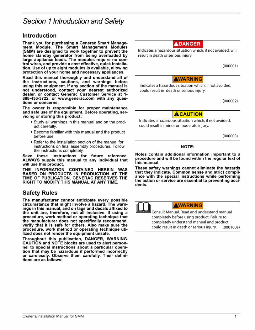
Safety RulesThe manufacturer cannot anticipate every possiblecircumstance that might involve a hazard. The warn-ings in this manual, and on tags and decals affixed tothe unit are, therefore, not all inclusive. If using aprocedure, work method or operating technique thatthe manufacturer does not specifically recommend,verify that it is safe for others. Also make sure theprocedure, work method or operating technique uti-lized does not render the equipment unsafe.Throughout this publication, DANGER, WARNING,CAUTION and NOTE blocks are used to alert person-nel to special instructions about a particular opera-tion that may be hazardous if performed incorrectlyor carelessly. Observe them carefully. Their defini-tions are as follows:
NOTE:
Notes contain additional information important to aprocedure and will be found within the regular text ofthis manual.These safety warnings cannot eliminate the hazardsthat they indicate. Common sense and strict compli-ance with the special instructions while performingthe action or service are essential to preventing acci-dents.
(000001)
DANGERIndicates a hazardous situation which, if not avoided, will result in death or serious injury.
(000002)
WARNINGIndicates a hazardous situation which, if not avoided,could result in death or serious injury.
(000003)
CAUTIONIndicates a hazardous situation which, if not avoided,could result in minor or moderate injury.
(000100a)
WARNINGConsult Manual. Read and understand manualcompletely before using product. Failure to completely understand manual and productcould result in death or serious injury.
Owner’s/Installation Manual for SMM 1
Introduction and Safety
This page intentionally left blank.
2 Owner’s/Installation Manual for SMM
General Information and Setup
Section 2 General Information and Setup
Figure 2-1. Features and Controls
Know Your Smart Management Module and Carton ContentsPriority Dial (A) – Sets module priority.
NOTE: PRIORITY MUST BE DIFFERENT for each module in an installation. Priority sets the order in which loads recover from a load shed event. Recovery time from a load shed event is five minutes for Priority 1. Each priority after Priority 1 waits an additional 15 seconds after the initial recovery time. See Table 1.
Lockout Switch (B) – Prevents load from operating when sys-tem is operating under generator power. See Table 2.
NOTE: Recovery time is based on priority dial settings. See Table 1.
Test Button (C) – Disables contactor output for a specifiedtime.
LED (D) – Provides module status. See Table 3.
Contactor (E) – Controlled by a smart controller in module.Contactor remains CLOSED until generator power is required.Upon generator activation, controller moves to OPEN to handleoverload conditions.
NOTE: The contactor is also opened during lockout switch ACTIVE state.
Priority Decal (G) – Provided for recording priority of eachmodule in installation. Should be installed on electrical panel.
000106
A
B C
D
E
FF
000143a
G
Table 1. Priority Dial Settings
Priority Recovery Time
1 5 minutes
2 5 minutes 15 seconds
3 5 minutes 30 seconds
4 5 minutes 45 seconds
5 6 minutes
6 6 minutes 15 seconds
7 6 minutes 30 seconds
8 6 minutes 45 seconds
9 Not Used
0 Not Used
Owner’s/Installation Manual for SMM 3
General Information and Setup
Table 2. Lockout Switch Settings
Lockout Switch
PositionMode Function
ON GENERATOR Power is NOT available on module output (contactor output). Contactor is OPEN.
ON UTILITY Power is available on module output (contactor output). Contactor is CLOSED.
OFF GENERATOR Module operates with standard load shed logic. Contactor is OPEN or CLOSED per logic.
OFF UTILITY Power is available on module output (contactor output). Contactor is CLOSED.
Table 3. LED States
State LED State Mode Note
Shed1 second flash (1 On – 1 Off)
GeneratorModule detected an overload and shed its load. This state only occurs in generator mode, or during a first time utility power up for five minutes of initial operation.
Lockout (30 minutes)
3 second flash (3 On – 3 Off)
Generator
Module detected an overload while trying to recover from a shed situ-ation. It identified the offending load and disabled operation for 30 minutes to allow other loads to operate. This state only occurs in gen-erator mode.
Lockout Switch Active
6 second flash (6 On – 6 Off)
GeneratorModule output is disabled and there is no power to the appliance while in generator mode. Lockout switch must be ON. See Table 2.
Lockout Switch Active
ON UtilityLockout Switch operates in generator mode only. It has no function in utility mode. LED is solid, indicating contactor is CLOSED and load is connected. Lockout switch must be ON. See Table 2.
Normal ON Generator or UtilityIndicates contactor is CLOSED and appliance has power. This is the default in utility mode. It is the normal operating state in generator mode when an overload is not detected.
Test 1 second flash Generator or UtilityTest button triggers a typical shed condition and overrides all other states except generator lockout switch ACTIVE state.
4 Owner’s/Installation Manual for SMM
General Information and Setup
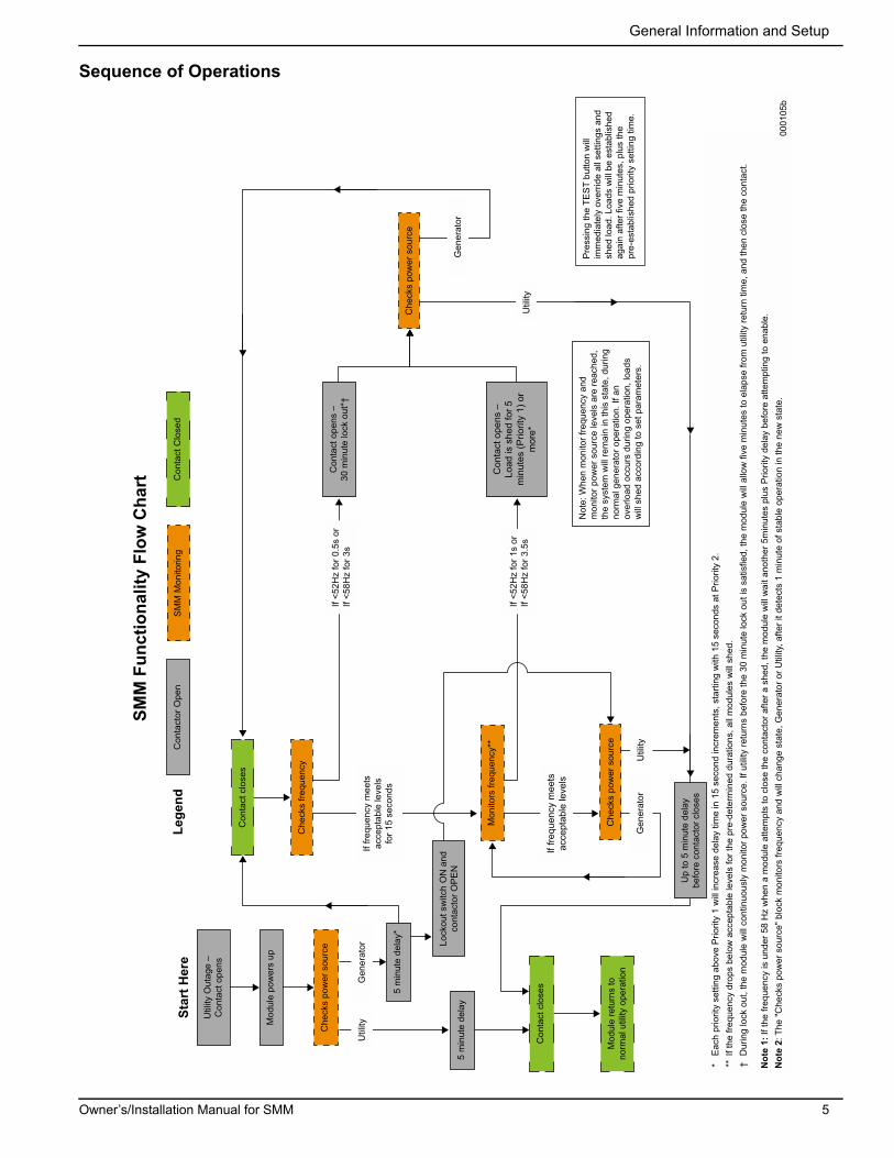
Sequence of Operations
SMM
Fun
ctio
nalit
y Fl
ow C
hart
Star
t Her
eLe
gend
Not
e: W
hen
mon
itor f
requ
ency
and
m
onito
r pow
er s
ourc
e le
vels
are
reac
hed,
th
e sy
stem
will
rem
ain
in th
is s
tate
, dur
ing
norm
al g
ener
ator
ope
ratio
n. If
an
over
load
occ
urs
durin
g op
erat
ion,
load
s w
ill s
hed
acco
rdin
g to
set
par
amet
ers.
* E
ach
prio
rity
setti
ng a
bove
Prio
rity
1 w
ill in
crea
se d
elay
tim
e in
15
seco
nd in
crem
ents
, sta
rting
with
15
seco
nds
at P
riorit
y 2.
** I
f the
freq
uenc
y dr
ops
belo
w a
ccep
tabl
e le
vels
for t
he p
re-d
eter
min
ed d
urat
ions
, all
mod
ules
will
she
d.†
Dur
ing
lock
out
, the
mod
ule
will
con
tinuo
usly
mon
itor p
ower
sou
rce.
If u
tility
retu
rns
befo
re th
e 30
min
ute
lock
out
is s
atis
fied,
the
mod
ule
will
allo
w fi
ve m
inut
es to
ela
pse
from
util
ity re
turn
tim
e, a
nd th
en c
lose
the
cont
act.
Not
e 1:
If th
e fre
quen
cy is
und
er 5
8 H
z w
hen
a m
odul
e at
tem
pts
to c
lose
the
cont
acto
r afte
r a s
hed,
the
mod
ule
will
wai
t ano
ther
5m
inut
es p
lus
Prio
rity
dela
y be
fore
atte
mpt
ing
to e
nabl
e.N
ote
2: T
he "C
heck
s po
wer
sou
rce"
blo
ck m
onito
rs fr
eque
ncy
and
will
cha
nge
stat
e, G
ener
ator
or U
tility
, afte
r it d
etec
ts 1
min
ute
of s
tabl
e op
erat
ion
in th
e ne
w s
tate
.
Util
ity
Util
ity
Util
ity
0001
05b
Gen
erat
or
Gen
erat
or
Che
cks
pow
er s
ourc
e
Che
cks
pow
er s
ourc
e
Con
tact
clo
ses
Con
tact
clo
ses
Con
tact
Clo
sed
Che
cks
frequ
ency
SM
M M
onito
ring
Lock
out s
witc
h O
N a
nd
cont
acto
r OP
EN
Up
to 5
min
ute
dela
y be
fore
con
tact
or c
lose
s
Mon
itors
freq
uenc
y**
5 m
inut
e de
lay
5 m
inut
e de
lay*
Mod
ule
pow
ers
up
Con
tact
or O
pen
Util
ity O
utag
e –
Con
tact
ope
ns
Con
tact
ope
ns –
Load
is s
hed
for 5
m
inut
es (P
riorit
y 1)
or
mor
e*
Con
tact
ope
ns –
30 m
inut
e lo
ck o
ut*†
Mod
ule
retu
rns
to
norm
al u
tility
ope
ratio
nC
heck
s po
wer
sou
rce
If fre
quen
cy m
eets
ac
cept
able
leve
ls
If fre
quen
cy m
eets
ac
cept
able
leve
ls
for 1
5 se
cond
s
If <5
2Hz
for 1
s or
If
<58H
z fo
r 3.5
s
If <5
2Hz
for 0
.5s
or
If <5
8Hz
for 3
sG
ener
ator
Pre
ssin
g th
e TE
ST
butto
n w
ill
imm
edia
tely
ove
rrid
e al
l set
tings
and
sh
ed lo
ad. L
oads
will
be
esta
blis
hed
agai
n af
ter f
ive
min
utes
, plu
s th
e pr
e-es
tabl
ishe
d pr
iorit
y se
tting
tim
e.
Owner’s/Installation Manual for SMM 5
General Information and Setup
This page intentionally left blank.
6 Owner’s/Installation Manual for SMM
Installation, Tests and Troubleshooting
Section 3 Installation, Tests and Troubleshooting
Electrical Specifications
Enclosure Specifications
Remove Contents from Carton1. Open carton.2. Remove and verify carton contents. 3. Retain carton for mounting template.
Carton Contents:
• Smart Management Module (SMM)
• Priority decal
• Owner/Installation manual4. Contact the place of purchase with the unit model num-
ber for any missing carton contents.5. Record date of purchase on front cover of this manual.
Tools Needed For Installation• Power drill and suitable drill bit
• Phillips and flat head screwdrivers
• Mounting screws or wall anchors
• Electrical materials
Mounting InstructionsThe recommended installation is near the electrical panel orappliance/load. The enclosure has a UL type 3R rating and canbe mounted indoors or outdoors. It provides a degree ofprotection against rain and sleet and is undamaged by theformation of ice on the enclosure.
1. Turn OFF both UTILITY (NORMAL) and EMERGENCY(STANDBY) power supplies.
2. Choose mounting location (near electrical panel,appliance or load to be managed).
3. Use a flat head screwdriver to remove appropriateknockouts from module enclosure for wiring. See A inFigure 3-1.
NOTE: If outdoor installation is chosen, bottom knockouts must be used to meet NEMA 3R rating and protect against water ingress.
4. Hold SMM enclosure against mounting surface witharrows pointing up, and mark or drill four mounting holes.See B in Figure 3-1 for arrows.
5. Install SMM enclosure to mounting surface using appro-priate mounting screws or wall anchors.
Figure 3 -1. Knockouts and UP Arrows
Figure 3 -2. Mounting Dimensions
Input Voltage 240 VAC
Current Rating 50A resistive, 40A inductive
Locked Rotor Amp Rating 240A
Motor Rating 3HP
Contactor Coil Voltage 240 VAC
UL Rating Type 3R
Temperature -30 to 50 deg C (-22 to 122 deg F)
(000116)
DANGERElectrocution. Turn utility and emergencypower supplies to OFF before connecting power source and load lines. Failure to do so will result in death or serious injury.
Height (in/mm)H1 6.17/156.8
H2 2.36/60
Width (in/mm)W1 7.06/179.4
W2 4.72/120
Depth (in/mm) D1 3.7/94
000138
A
A
A
B
W1
W2
H2H1
D1
000107
Owner’s/Installation Manual for SMM 7
Installation, Tests and Troubleshooting
Connections
Figure 3 -3. Wiring Diagram
1. Turn OFF both UTILITY (NORMAL) and EMERGENCY(STANDBY) power supplies before connecting powersource and load lines to transfer switch and SMM.
NOTE: Suitable conduit fittings must be installed in knockout openings when running supply and load wires.
NOTE: Use at least 75 ºC rated wire and gauge per installa-tion instructions. Refer to table for recommended wire size based on load current.
2. Run line supply wires per applicable NEC code articlesfor wiring method selected.
3. Run load wires per applicable NEC code articles forwiring method selected.
4. Connect line supply wiring to line side of SMM contactorfield terminals. See Figure 3-2. Tighten field terminals to25 in-lbs (2.8 Nm).
5. Connect load supply wiring to load side of SMMcontactor field terminals. See Figure 3-2.
NOTE: If neutral and ground wires are included, connect inside SMM using a listed termination device.
The unit is now ready to apply power and perform testing.
Setting PrioritiesHigh priority 240 VAC loads should be set to the highestpriorities so those loads recover first, in the event of generatoroverload.
NOTE: The highest priority, and first load to activate is Priority 1. The last load to activate is Priority 8.
Setting priority determines timing for 3 scenarios:
• Order in which loads recover
• Delay time until power returns during an outage
• Delay time for post load shed recovery
An example configuration is shown below. Configurations willvary depending on customer prioritization of loads:
Priority 1 - Baseboard heatPriority 2 - Air conditionerPriority 3 - RangePriority 4 - DryerPriority 5 - Non-essential circuitsPriority 6 - Pool pump or hot tubPriority 7 - Other circuitsPriority 8 - Other circuits
1. Set the priority of each SMM module as desired (usingthe example configuration for reference).
2. Apply priority decal in a suitable location on electricalpanel to record chosen priority designations.
3. Record priorities on decal.
Setting LockoutMost installations will require the lockout switch will beDISABLED. When performing a whole house backup with agenerator not sized to manage all household loads, SMM's canbe used to disable appliances or circuits during an outage. Fornon-essential loads that will not be used on generator power,set lockout switch to ENABLED.
Tests
Utility Test
1. Turn utility power ON and enable all module feedingcircuits.
2. Verify LED begins to flash at one second intervals.3. All contactors will close after five minutes. LED will
illuminate, and stay ON.4. Wait 30 seconds after contactor closes, then press TEST
button and verify module load shed. LED will flash at onesecond intervals.
5. Wait five minutes, plus predefined priority set time formodule to recover.
6. Contactor will CLOSE and LED will illuminate, and stayON.
DANGERElectrocution. Turn utility and emergencypower supplies to OFF before connecting power source and load lines. Failure to do so will result in death or serious injury.
8 Owner’s/Installation Manual for SMM
Installation, Tests and Troubleshooting
Generator Test
1. Simulate a utility loss by turning main line circuit breaker(MLCB - service disconnect) to OFF while generator is inAUTO.
2. All modules will lose power and LEDs will disable. 3. Generator will power on after preset delay. 4. All LEDs will flash when generator transfers.5. Allow each module to enable output per its priority set-
ting.6. After predefined priority time elapses, each contactor will
CLOSE and LED will illuminate and stay ON.7. Once LED stays ON, press TEST button and verify load
shed occurs.8. Once load shed occurs, LED will flash at one second
intervals.9. Allow time for each module to enable contactor output
per priority setting.10. After predefined priority set time, each contactor will
CLOSE and LED will illuminate and stay ON.
NOTE: Depending on load size, the SMM module may imme-diately go into load shed mode or lockout during test. In this event, remove one or more higher priority loads to allow testing of each module.
Generator Test with Lockout Switch Enabled (perform if Lockout Switch Enabled on any loads)
1. Simulate a utility loss by turning MLCB (service discon-nect) to OFF while generator is in AUTO.
2. All modules will lose power and LEDs will disable. 3. Generator should power on after preset delay.
NOTE: For modules with lockout switch enabled, LEDs will flash at six second intervals and load will remain disabled while in generator power.
Return to Utility Test
1. Return utility power by setting the MLCB (service discon-nect) to ON.
NOTE: All modules should begin flashing at one second inter-vals.
NOTE: All modules will recover in five minutes (including units with lockout switch enabled).
Installation Summary
• Install cover on electrical panel.
• Install covers on modules.
TroubleshootingSee Table 4 for troubleshooting problems, causes and correc-tions.
Table 4. Troubleshooting
Problem Cause Correction
Load not powered, LED is OFF Circuit Breaker disabled. Enable Circuit Breaker
Load not powered, LED is OFF MLCB disabled and generator OFF. Enable MLCB if utility is present or verify generator operation if outage.
Load not powered, LED flashing 1 sec-ond interval.
Generator power just applied to unit.Utility power just applied to unit.Generator was overloaded and shed occurred.
Wait 5 minutes plus the priority time delay (see Table 1) for unit to enable output.
Load not powered, LED flashing 3 sec-ond interval.
This load overloaded the generator while attempting recovery from a shed. It is in a 30 minute lockout wait period.
Wait 30 minutes from lockout for unit to attempt to re-apply load.Review all loads enabled in household. The generator may end up in another overload condition when this load is enabled. Disable some loads to prevent generator overload from recurring.
Load not powered, LED flashing 6 sec-ond interval.
The lockout switch is enabled and the unit is on generator power.
During installation, it was determined that this load will be disabled during generator operation to prevent generator overload. Contact servicing dealer for details.
SMM module is humming.
NOTE: A normal 60 Hz hum is expected from the normally open contac-tor. Excessive hum may be caused by one of the following:
1. Improper mounting.
2. Contactor error or connections notcorrect.
1. Mount to wall or vertical surface witharrows pointing up only.