NATIONAL RADIO ASTRONOMY OBSERVATORY SOCORRO, NEW MEXICO VERY LARGE ARRAY PROGRAM VLA ELECTRONICS MEMORANDUM NO. 206 VLA 327 MHz PROTOTYPE FEED SYSTEM P. NAPIER Introduction Since the VLA subreflector is only 2.6 wavelengths in diameter at 327 MHz and because a 327 MHz Cassegrain feed would need to be approximately 6.3m in diameter, it is obviously not feasible to place the 327 MHz receiver at the secondary focus. The rms deviation of the VLA main reflector from the best fit parabola is 1.0 cm which will cause negligible loss of gain for a prime focus 327 MHz feed. Clearly, then, the 327 MHz receiver system should be placed at the prime focus. The design goals for the feed system design were as follows (more or less in descending order of importance). (1) The complete receiver/feed system must be inexpensive enough so that 28 systems could be constructed from available 00E funds. $5K to $10K per system is a reasonable goal. This clearly rules out an automatic mechanism to move the subreflector in and out of position. (2) It must not be necessary to manually remove the subreflector to use the 327 MHz system. Estimates by the VLA Antenna Division show that, with available manpower, at most 4 antennas a day could have their subreflectors removed and 327 MHz Systems installed. Thus, 7 working days would be needed to convert the array to 327 MHz 1
Transcript
NATIONAL RADIO ASTRONOMY OBSERVATORY SOCORRO, NEW MEXICO
VERY LARGE ARRAY PROGRAM
VLA ELECTRONICS MEMORANDUM NO. 206
VLA 327 MHz PROTOTYPE FEED SYSTEM P. NAPIER
Introduction
Since the VLA subreflector is only 2.6 wavelengths in diameter at
327 MHz and because a 327 MHz Cassegrain feed would need to be
approximately 6.3m in diameter, it is obviously not feasible to place
the 327 MHz receiver at the secondary focus. The rms deviation of the
VLA main reflector from the best fit parabola is 1.0 cm which will
cause negligible loss of gain for a prime focus 327 MHz feed.
Clearly, then, the 327 MHz receiver system should be placed at the
prime focus. The design goals for the feed system design were as
follows (more or less in descending order of importance).
(1) The complete receiver/feed system must be inexpensive enough
so that 28 systems could be constructed from available 00E funds. $5K
to $10K per system is a reasonable goal. This clearly rules out an
automatic mechanism to move the subreflector in and out of position.
(2) It must not be necessary to manually remove the subreflector
to use the 327 MHz system. Estimates by the VLA Antenna Division show
that, with available manpower, at most 4 antennas a day could have
their subreflectors removed and 327 MHz Systems installed. Thus, 7
working days would be needed to convert the array to 327 MHz
1
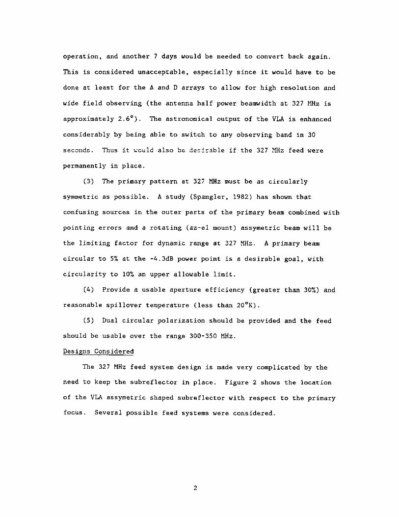
operation, and another 7 days would be needed to convert back again.
This is considered unacceptable, especially since it would have to be
done at least for the A and D arrays to allow for high resolution and
wide field observing (the antenna half power beamwidth at 327 MHz is
approximately 2.6°). The astronomical output of the VLA is enhanced
considerably by being able to switch to any observing band in 30
seconds. Thus it would also be desirable if the 327 MHz feed were
permanently in place.
(3) The primary pattern at 327 MHz must be as circularly
symmetric as possible. A study (Spangler, 1982) has shown that
confusing sources in the outer parts of the primary beam combined with
pointing errors and a rotating (az-el mount) assymetric beam will be
the limiting factor for dynamic range at 327 MHz. A primary beam
circular to 5% at the -4.3dB power point is a desirable goal, with
circularity to 10?& an upper allowable limit.
(4) Provide a usable aperture efficiency (greater than 30%) and
reasonable spillover temperature (less than 20°K).
(5) Dual circular polarization should be provided and the feed
should be usable over the range 300-350 MHz.
Designs Considered
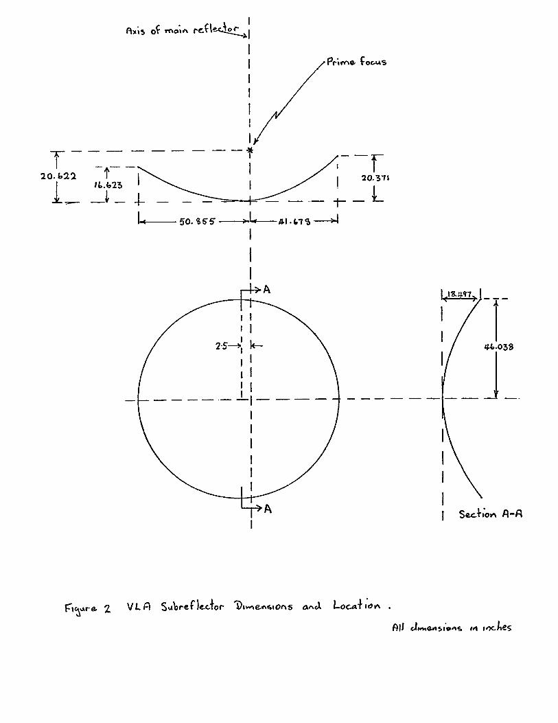
The 327 MHz feed system design is made very complicated by the
need to keep the subreflector in place. Figure 2 shows the location
of the VLA assymetric shaped subreflector with respect to the primary
focus. Several possible feed systems were considered.
2
Dipoles mounted in front of the Subreflector
A pair of dipoles for each linear polarization could be mounted
r
on the face of the subreflector as shown in figure 1. Circular
polarization could be formed using a hybrid. The subreflector would
then act as a curved, assymetric, ground plane for the dipoles.
The nominal position of the subreflector is shown in Figure 2.
The subreflector mount allows db 6 inches of travel about this nominal
position, but approx 2 inches of this is used up in correcting for
differences between antennas. Thus, the phase center of such a dipole
feed (Jasik, 1961; Christiansen and Hogbom, 1969) which would be close
to the subreflector surface, could be placed approximately 16.6 inches
(0.5X) from the prime focus. The loss of gain as a function of
defocussing for the VLA 25m reflector, calculated from formulas given
in Ruze (1969), is shown in Figure 3. The predicted gain loss is -1.7
dB (efficiency reduced by a factor of 0.68). This gain loss would
possibly be bearable, but other factors make this feed unattractive.
The effect of the assymetric curved subreflector on the radiation
pattern of the dipoles is almost impossible to predict accurately. A
large antenna range would be needed to measure the patterns
experimentally. The effect of the dipoles on the performance of the
Cassegrain feeds is also difficult to determine. Finally, a receiver
mounted on the back side of the subreflector would be extremely
inconvenient to install and maintain because this region is blocked by
the subreflector support structure.
3
Flat Dipoles mounted on the Subreflector
B. Clark has suggested that flat dipoles could be made right at
the subreflector surface by making cuts in the thin aluminum
conductive coating of the fiberglass subreflector. In this case the
dipoles would be within 0.5X of the prime focus and the defocussing
loss of -1.7dB might be bearable. This feed suffers from the same
disadvantages as the dipole feed. If the current design proves
inadequate, however, Clark's idea and the dipole feed should be
investigated further.
Large Dipole Array In Front of Subreflector
One could conceive of a large, two dimensional array of dipoles
in front of the subreflector, with the complex excitation of the
elements chosen to give the correct amplitude pattern and an apparent
phase center at the prime focus. This idea was not pursued because of
its complexity and because such a feed would have to be moved in and
out of position.
The concept finally chosen was a compact feed placed off axis at
the edge of the subreflector.
The Prototype Prime Focus Geometry
The feed element chosen is a "crossed-dipoles-in-a-cavity" feed
(Wong and King, 1973; Ruze, 1976.) This type of feed is commonly used
at Greenbank as a prime focus feed. It has adequate spillover
efficiency and beam circularity and is inexpensive. The scalar feed
has better performance but is more expensive and, because it is
larger, would have to be located further off axis. Figure 4 shows the
4
location of the feed with respect to the subreflector in its fully
retracted position. The feed must be located far enough off axis to
clear the largest radius of the subreflector. In this position the
feed is 67.7 in (1.87 X) off axis.
The feed element described below has a pattern taper of approx
-11.9dB at the edge of the main reflector at 327 MHz. This, together
with a space factor loss at the dish edge of -3.4dB gives an aperture
distribution with a total edge taper of ~15.3dB. Comparison of the
measured feed patterns with the families of circular aperture
distributions presented by Hansen (1964, Page 65) shows that the
expected aperture distribution at 327 MHz is closely approximated by a
distribution of the form f(r) = 0.25 + (1-r2)3 , where r is normalized
radius.
The primary beam properties of this distribution, in the absence
of blockage or aberration are as follows.
3dB Beamwidth = 1.25 X/D = 2.63° at 327 MHz.
Aperture Taper Efficiency = 0.79
First Sidelobe Level = -32dB
First Null = 1.97X/D = 4.14° at 327 MHz.
The antenna performance with the feed 1.87 X off axis can now be
estimated using the curves presented by Ruze (1965). These curves are
reproduced as Figure 5, with the approximate operating points for the
VLA 327 MHz feed marked. A feed lateral displacement of AX will cause
a beam scan of (AX/F) BDF, where F is the focal length (9.0m) and BDF
is the Beam Deviation Factor. From Fig. 5, BDF = 0 . 8 0 giving a
5
predicted beam scan (pointing offset) of 8.8° (3.3 bearawidths). The
327 MHz feed will be located directly over the LBand Cassegrain Feed.
The pointing offset is in the plane containing the 327 MHz feed and
the axis of the main reflector and is in the direction opposite to the
direction of the lateral offset (see inset in Figure 6). The quantity
X in the curves in Figure 5 is 22 for 3.3 beamwidths scan and F/D =
0.36. These curves predict the following: in the plane of the scan
the 3dB beamwidth will broaden by 7% and the lOdB beamwidth will
broaden by 14%. The coma lobe, on the axis side of the offset beam,
will increase to approx 12dB. The loss of gain is approx -l.OdB.
The beam assymetries predicted above are just within Spangler's
(1982) limits, although it should be noted that Spangler assumed an
elliptical gaussian beam for his analysis. The data in Ruze (1965)
shows that this is not an appropriate model beyond the 3dB beamwidth.
Figure 4 shows that, even with the subreflector in its fully retracted
position, the subreflector comes close to blocking a part of the main
reflector. This, together with the assymetric location of the feed
with respect to the feed legs, could give rise to significant
assymetry in the aperture illumination. If tests show that the
primary beam is unacceptably assymetric, a holographic measurement of
the aperture distribution (Napier, 1982) should reveal the cause.
Figure 6 shows the overall assymetry of the geometry and shows
the optimum tilt of the feed to get best symmetry of illumination in
the dish aperture.
6
Note that Ruze (1965) and Rusch (1976) predict that the focal
point in the off axis location will be AX2/2F (0.18X) further away
from the main reflector vertex than the nominal prime focal point.
Figure 3 predicts a -0.3dB gain loss due to this defocussing, some of
which can be recovered by moving the feed as far back as subreflector
blockage will allow.
Finally, the off-axis feed will cause the circularly polarized
beams to point in slightly different directions. The curves in Chu and
Turrin, (1973) predict that the right and left polarized beams will be
separated by 0.05 beamwidths in the sky.
The Prototype Feed Element
The prototype feed design was scaled from a Greenbank design
provided by R. Fisher and J. Coe. Examination of Greenbank measured
feed patterns showed that an edge taper of approximately -12dB would
give a taper efficiency slightly below optimum, but the increased
taper would reduce the effect of the lateral feed displacement and
give a reduced spillover temperature contribution.
The feed design chosen to provide this illumination is shown in
Figure 7. Figure 8 shows the measured feed patterns for 300, 325 and
350 MHz. These patterns were measured on a simple antenna range
constructed at the VLA. Table 1 shows the measured reflector edge
taper.
7
f (Mhz E H
300 -lO.OdB -10. 7dB
325 -11.4 -12. 3
350 -11.7 -13. 0
Table 1. Feed pattern taper at ±70°.
The patterns were integrated (Leonard - Napier, 1973) to give
predictions of efficiency and spillover temperature. This data is
tabulated in Table 2, in which E and H plane data have been averaged
together. The spillover temperature
f (MHz) TaperEfficiency
\ %
SpilloverEfficiency
\ %
FeedEfficiency
\ XT)s %
Ground Spillover Temperature (°k)
300 85 84 71 24325 83 87 72 20350 83 88 72 21
Table 2. Efficiency and Spillover Calculations
calculations are uncertain by 20%. The spillover temperatures are
higher than desired but probably bearable considering that sky
temperature will vary between 34°K in directions near the Galactic
pole and 450°K towards the Galactic Center. Figure 9 shows Kraus’
(1966) data for sky temperature. Note that the feed taper efficiency
of 0.83 is in reasonable agreement with the efficiency of the model
aperture distribution of 0.79.
The predicted aperture efficiency for the feed system can now be
obtained as the product of the feed efficiency (0.72), blockage
8
efficiency (0.85), coma loss (0.79), defocussing loss (0.93),
insertion loss (0.93) to give a total of 0.42. Experience would
predict that this estimate is only accurate to 10%, especially given
the uncertain effects of subreflector and feed leg blockage.
Figure 10 shows the measured return loss of the feed which was
optimized by experimentally adjusting the dipole length and the size
of the matching plates in front of and behind the dipoles. Circular
polarization will be provided using a 90° hybrid located after the
preamplifiers if the amplifiers can be well enough matched in
amplitude and phase, or, otherwise, in front of the amplifiers.
The cost of the feed and its mounting structure is less than $500.
Future W o r k . After the prototype feed is rebuilt in permanent form
and mounted on antenna 12, careful tests will be needed on focus
664 IEEE TRANSACTIONS ON A NT EN NAS AND PROPAGATION September .
Half-power beamwidth.
. . . -t-\v* ‘•Jy «
Loss of gain.
Beam deviation factor.
Tenth-power beamwidth.
X
Coma lobe. Region of validity.
5 \ Curu^SVLA 32.7 HVx. o^ro^i^a't'e a exc*4-\no iS **iCxr ke<A %
317 H Ha. F E E D SYSTEM
fVct Co,-Aer
I Lh.
X
Fi u e 7 . Pfofo^jJe feed
300 MVyZ. £ PVovfxe.
r e l fi r i y e s r r e n g t h , d b
- 1-31 -1
- 2 0 '
- 7 0 -
3oO M Hz HR E L R r I y E -3 f R E H G T H .. d B
\_V lC'C(t& ~ l 0
- 1 s 4-
~ 2 0 t S
A - l0--7^6
\ /
-ISO -SO o
D I R E C TI 0 N
— i !ISO -i*o
---h ------- 1-------~Ho o
DI RE C TI 0 N
325" H K i £ Plar>eR E L R T I y E S T R E H G f H , d B
0 T
3Z5 MWz H Pl.ft.oeR E L R T I y E S r R E N G T H , d B
- 1 0;*.__
- 1 5"
2 0 ”
- 2 F . ’. r \ i
■/
/ —H-4 <*8
\V
'Iso "90 O 90
D I R E C T I 0 N
-i---------
/
I
90 130
3 S O f*\V\z £
R E L H T I E 3 IRE N G T H , d B
- 1 0 +
- 1 5- 2 0 1
- 7 0 -
\— — V— 7J6
3 S’o M U x H P U a &
R E L R T I V E 3 T R E H G T H , d B
- 1 0
- 1 F +
- 2 O t
- 7 0
-90 O 90
DI RECT I O N130 -iflp
1I /
U
0 90D I R E C T I 0 N
1%Q
F ig u r e , ^ . Pr^-UKjpc, 3 ^ 7 HWz. IneeJ K casured {^jed .
F req u en cy
Antenna sky noise temperature as a function of frequency and antenna angle. A beam angle (HPBW) of less than a few degrees and 100 percent beam efficiency are assumed. (After Kraus and Ko, 1957, cosmic noise below 1 C.c; Penzias and Wilson, 1965, and Dicke ct al., 1905, cosmic noise above 1 Gc; Croom, 1904, atmospheric noise; and CCIIl, 1964, atmospherics).