.. ' 1lilliiillMIIII [) lolob[] [)[)S2Sb4 b SDC-90-00123 soc SOLENOIDAL DETECTOR NOTES HYBRID CENTRAL lRACKING CHAMBER COLLABORATION, Summary Report - Part II: Proposal for FY91 Contact person: A. T. Goshaw August 1990
Transcript
~.. '1lilliiillMIIII
[) lolob[] [)[)S2Sb4 b
SDC-90-00123
socSOLENOIDAL DETECTOR NOTES
HYBRID CENTRAL lRACKING CHAMBER COLLABORATION,Summary Report - Part II: Proposal for FY91
Contact person: A. T. Goshaw
August 1990
"
<>:
Hybrid Central Tracking Chamber Collaboratiun
Summary Report - Part n: Proposal for FY91
Submittedto
PhysicsResearchDivisionSSC Laboratory
2550Beckleymeade AvenueDallas. TX 75237
.'-~.:»<t....
.....
,"
..-.)(;F.""
se
e
...... -~~..... ,-
"'~.. ~o
......- ....
. ., .
...
.*"' .*"' : ~ ,. x..... -)Ie..)0
Prepared by
Continuous Electron BeamAccelerator Facility
DukeUniversityFlorida StateUniversityGeneral Electric Canada Inc,KEKNorth Carolina StateUniversity
Northeastern UniversitvOak Ridge National LaboratoryQuantum Research ServicesSupercomputer Computations
Research InstituteTRIUMFUniversity of Pennsylvania
August 1990
Collaboration Members
-,
I
•
Continuous Electron Beam Accelerator Facj!jty
puke University
Florida State University
General Electric Canada Inc.
t\orth Carolina State University
Northea;tem Universiry
Oak Ridee National Laboratory
Quantum Research Sen;ces. Inc.
Supercomputer Computation Research Instirute
TRIm.iF
Univer;itv of Penn<vlvania
Prim3l""\' Contact Person'
ii
Dr. Stan MajewskiDr.CarlZomDr. Alfred T. Goshaw (Co-spokesman)Dr. Seog OhDr. William Robertson
Dr. Vaskan HagopianMr. Phil Rulon
Dr. Robert McIntyreDr. Henri DautetDr. Hirokazu IkedaDr. Yasuo Arai
Dr. John PaulosDr. Thomas S. Elleman
Dr. Stephen Reucroft (Co-spokesman)Dr. George Alverson .Mr. Addison GrimesDr. Mike GlaubmanDr. Ian Leedom
Dr. Tony GabrielMr. Gary AlleyMr. Hugh BrashearMr. Charles L. Britton, Jr.Mr. Michael EmoryDr. Raymond E. Garvey, IIIDr. Charles GloverDr. Richard A. LillieMr. Brad NelsonMr. Ted RyanMr. David Vandergriff
Dr. William L. DunnDr. Fearghus O'FoghludhaMr. Joseph D. SimpkinsDr. A.M. Yacout
Dr. Martyn CordenDr. Mike Mermikides
Dr. Martin SolomonDr. Robert HendersonDr.Wayne FraszerMr. Robert Openshaw
Dr. Rick Van Berg
Dr. Alfred T. GoshawPhysics DepartmentDuke UniversityDurham, NC 27706\9 i 9) 684-8134DUKHEP::GOSHAW
.r: Hybrid Central Tracking Chamber Collaboration
Summary Report - Part II: Proposal for FY91
Section
1.0 Executive Summary1.1 Introduction1.2 OverviewofFY1991 R&D program1.3 acre development in FYl992
2.0 Straw Tube Drift Chambers (Task 1)2.1 Straw rube construction2.2 Superlayer construction2.3 Development and testing ofreadout electronics2.4 Gas selection and aging studies2.5 Radiation hardness studies2.6 Task timeline
3.0 Scintillating Fibers (Task 2)3.1 Fiber studies3.2 Ribbon fabrication and superlayer construction3.3 Development and tests ofreadout devices3.4 Radiation hardness studies3.5 Task timeline
4.0 Mechanical Engineering (Task 3)4.1 Straw tube layout cylinder4.2 Carbon composite cylinder design and prototype fabrication4.3 End plate design and prototype fabrication4.4 Support structure design4.5 Assembly and alignment concepts4.6 Task timeline
5.0 Monte Carlo Simulation ofHerC (Task 4)5. 1 Detector response simulation5.2 Reconstruction studies5.3 Panem recognition studies5.4 CAD Interfacing5.5 Optimization of parameters5.6 Background and radiation damage srudies5.7 Task timeline
6.0 Administration6. 1 Project organization and personnel6.2 FYl991 Budget by institution and by task6.3 Projected FY 1992 budget
References
iii
I
. /"'"""
,.1.0 Executive Summary
1.1 Introduction
During the past year, the Hybrid Central Tracking Chamber (HCrC)
Collaboration has established a comprehensive research program designed to
develop a large volume tracking detector for the SSC. The HCTC detector conceptand a detailed description of our R&D results from FY1990 are presented in Part I of
this Summary Report. The conclusions of our first years work are that the HCrCdetector concept is sound and appears to be a highly attractive option for particletracking in the central rapidity region of an SSC detector. This Proposal describes anatural continuation of our HCrC detector development into FY1990. The
proposed R&D program is broad enough to test all critical features of the HCrCdesign. It includes the construction of prototypes which will investigate thefabrication and automation procedures needed for the construction of a full scale
detector. We will also develop a detailed Work Breakdown Study (WBS) and cost
estimate for the construction of a HCrC for the SDC detector. As discussed in more
detail below, we have made contacts with other tracking subsystem groups tocoordinate R&D work where possible.
1.2 Overview of FY1991 R&D program
t The R&D program spans four tasks that are basic to development of the HCrCdetector: straw tube drift chambers (task I); scintillating fiber tracking (task 2);
mechanical engineering (task 3); and Monte Carlo detector simulation and pattern
recognition (task 4). Readout electronics development and radiation hardness
studies are distributed over tasks 1 and 2. The details of our program are presented
in Sections 2 to 5 of this Proposal. Section 6 summarizes the administration of theproject. This includes responsibilities of personnel and institutions, a projecttimeline with milestones and the FY199I budget by institution and task.
Some of the major R&D goals of the HCrC Collaboration for FY1991 aresummarized below.
•
Task 1: straw tube drift chambers• continued evaluation of existing 2.7 meter straw tube superlayer
1-1
• construction of long (-6 meter) straw tubes with midtubeterminators
• construction of a straw tube superlayer on a cylinder; study of '-Jassembly automation procedures
• frontend electronics testing and assembly into end plate ring• gas selection and aging studies• radiation hardness evaluation of all components
Task 2: scintillating fiber tracking• study optical and mechanical properties of fibers and ribbons• development and testing of avalanche photodiode arrays• radiation hardness evaluation of all components
Task 3: mechanical engineering• carbon composite cylinder design and prototype fabrication• end plate design and prototype fabrication• support structure design, assembly and alignment concepts• WBS with cost estimate for complete HCTC detector
Task 4: Monte Carlo simulations• detector response and pattern recognition studies• optimization of HCTC parameters within SDC detector• evaluation of neutron backgrounds in central tracking chambers
As our Progress Report has shown, we have made steady advancement inmost, of the areas listed above. For FY1991 we have further strengthened ourCollaboration. The addition of University of Pennsylvania, KEK and an electronics
group from ORNL have made it possible for us to quickly evaluate and improvereadout electronics. Mechanical engineering has always been a strength of the
HCrC collaboration. OR..>.,JL will broaden their engineering contribution to theHCTC effort in FY1991.
The HCTC work will be coordinated with ongoing SSC Subsystem R&D effortswhere useful. We will make direct use of the frontend electronics being developedby the Frontend Electronics Subsystem Collaboration (PC031, Williams, et al.) and byKEK. Rick Van Berg (University of Pennsylvania) and Hirokazu Ikeda (KEK),members of our collaboration, will expedite the transfer of electronics developed bythese groups to our straw tube superlayer prototypes. We will cooperate with thestraw tube work of the Wire Chamber Subsystem Collaboration (PC024, Hanson, et.al.) where possible. We note that the R&D work needed to develop the straw tube
1-2
.r>
t·
•
".
•r--
•
modules being proposed by Hanson, et al., differs significantly from the HCTCconcept, and therefore parallel R&D efforts are required. We will be working closelywith the Scintillating Fiber Tracking Subsystem Collaboration (PC023, Atac, Elias,Ruchti, et. al.) since this group will also be developing scintillating fiber superlayerson carbon composite stable base cylinders. Finally, we have agreed to closelycooperate with a group proposing a new Subsystem Proposal (A Compact CentralTracker for the sse, Ahlen, et. al.). This group also recognizes the advantages of theHCTC concept but will direct it toward an application in the smaller trackingvolume of the L· detector.
1.3 HCTC development in FY1992
Our FY1991 R&D program will examine all the critical features of the HCTCdesign and will probably identify some areas needing further study. The detailscannot be specified at this time, but the general program is clear. If the HCTCtracking system emerges as a viable option for one or more sse detectors, we wouldconstruct at least one full-scale carbon composite cylinder with end plate rings. Thiscylinder would be used to develop and perfect the automated assembly of straw tubeand scintillating fiber superlayers. We anticipate that major developments of front
end readout electronics will be continuing in FY1992 and these would beincorporated into the geometric constraints imposed by the end plates. In addition,we anticipate a need to continue a modest investigation of radiation hardness ofplastic scintillating fiber, in view of the complexity and importance of this issue.
The FY1992 program would therefore produce one or more full-scale HCTCsuperlayers which would be partially instrumented for readout using state-of-the-artelectronics. These superlayers would be subjected to a variety of mechanical,electrical and radiation hardness tests and their measurement performanceevaluated in particle test beams.
1-3
·1
,
t
•
2.0 Straw Tube Drift Chambers (Task 1)
In the HCTC design the majority of the precise, large-volume tracking isprovided by straw tube drift cells. A central theme in the design is simplicity ofmechanical construction (straw tubes laid axially on support cylinders). This willproduce maximum overall measurement precision and, we believe, result in adetector which is of lower cost than other alternatives.
Because of the critical importance of straw tube superlayers to our design, alarge fraction of the HCTC effort will be devoted to basic straw drift tubedevelopment (this task) and the mechanical engineering of support structures (task3). This section describes our straw tube R&D program. The work includes theconstruction of superlayers on a cylinder and the development of realistic end platerings containing gas flow, electronics and cooling. Electronics provided by Penn andKEK will be promptly adapted to and evaluated with our straw tube superlayers.We will continue our gas selection and aging studies, and the radiation hardnessevaluation of all other superlayer components.
2.1 Straw tube construction
As described in the progress report, we have completed construction of a 2.7meter long straw tube prototype array consisting of 60 tubes, 28 of which have beenstrung with sense wires. They are holding high voltage and signals are seen bothfrom cosmic rays and beta and gamma sources using several different types ofpreamplifiers. We are in the process of instrumenting these signals with availableamplifier-discriminators and CAMAC TDC's to do studies of the superlayer'sresolution using cosmic rays.
We will also be conducting tests of amplifler-shaper circuits being developed atPenn and KEK as they become available. We have prototype chips from both Pennand KEK which have been mounted on circuit boards and have been connected tothe readout end of the straw tube sense wires. The KEK chip has five channels andthe Penn chip contains a single channel. For straw tube detector operation in theSSC environment it is important to reduce the operating voltage as much aspossible. To achieve good resolution at the lower voltage the signal to noise of theamp-shaper-discriminator will have to be excellent; careful circuit board design will
2-1
be essential. We are relaying the results of our tests to the designers to assist in -Jdevelopment of the next generation of circuits.
In the coming year we will continue to study manufacturing techniques for oursense wire support design with the help of private companies. Presently, we areevaluating prototype samples developed by an injection molded plastics company.Careful measurement with a microscope shows that the center of the spiral hole inthe 2.5 cm long pieces is offset by about 120 microns. We have discussed this with
the company and a second generation sample of 1.2 em length is in design andproduction at this time.
The straw tubes we have used for the prototype array are constructed of 50micron mylar with 12 micron aluminum cathodes. Tubes of different material andthickness are being studied. We will purchase several different types of tubes forelectrical, mechanical and radiation hardness testing.
To reduce cell occupancy in the central tracking chamber it will be necessary toconstruct the superlayers of two half length arrays. In order to avoid the presence ofadditional material in the detector at the midpoint, we have devised a scheme tomake a straw tube cell which is electrically composed of two isolated detectors butwhich is a single mechanical element, thus eliminating the need for wire tensionsupport in the middle. Figure 2-1 illustrates the concept we intend to develop. Thiswill require research and development in several areas. The sense wire will have tobe constructed so it has a nonconducting segment in the middle with mechanicalproperties similar to the sense wire material (tensile strength, diameter, etc.). Thesense wire on either side of the central insulator will have to be terminated to thecathode coating on the inside of the straw tube through about 300 ohms resistance.A capacitive coupling to provide an AC ground at the midpoint of the cell will alsobe necessary. We believe our scheme for terminating the wire at the midpoint willbe a straightforward development task which we expect to complete over thecoming year.
To facilitate studies of mid wire termination schemes we will construct a ~5 mstraw tube cell. This apparatus will also be useful for extending our studies of signalattenuation.
2-2
• ).. r (' • ) . .' .. ')...
High Resistive Section. 'Iube wilh smaller radius.
o 300 ohm.
• 3 melers. • I • 3 meters, olII~I----
-JI \ 7 \ /:t \ 7rtf'.. 'C/
W;,. Support, 1J- JlV S.... WI,.
~w
Figure 2-1. Conceptual representation of proposed mid-tube termination.
2.2 Superlayer construction
A major project for the coming year will be construction of a cylindricalprototype chamber at ORNL. The proposed cylinder is to be about 60 to 80 em in
radius and 3 meters long. After construction, it will be transported to Duke for straw
tube assembly. The number of straw tubes to be attached to the cylindrical surfacewill be about 500, compared to 60 in the present prototype array (still 8 layers deep).
This project will demonstrate the ability to lay straw tubes on a cylindricalsurface with precision alignment and will allow us to investigate methods ofautomating superlayer assembly as much as possible. We will also test end platedesign for a superlayer on the cylindrical prototype. End plate design is critical since
electrical. mechanical. cooling and chamber gas supply and power connection aredone through the end plate. For the cylindrical prototype, the end plate design
concept will be similar to that used on the present 2.7 m prototype array, consistingof two thin walls with a space between to serve as a gas supply plenum to the strawtubes,
Finally, we will test the first compact front end electronics packages from KEKand/or Penn, depending on availability. Emphasis will be on testing for cross talk -'and noise pickup, These will be directly influenced by the end plate construction.
2.3 Development and testing of straw tube readout electronics
2.3.1 Overview
An electronic readout system will be developed for a portion of thecentral tracking prototype. Because of the costs associated with constructing a full
sized cylinder made from composite materials and the costs of instrumenting a fullsized cylinder, it has been decided to construct a cylinder using a less expensivematerial and only instrument a portion of the channels for readout. Therefore, out
of the few hundred straw tubes we plan to install, approximately half of these
channels will be instrumented at anyone time. We believe critical issues such ascrosstalk, packaging, materials, and mechanical alignment can be addressed usingthis more cost-effective approach. The ultimate goal is to develop readoutelectronics modules that can be interchanged quickly. To that end we plan toimplement the readout electronics in plug-compatible modules incorporating
2-4
t
I
•
custom integrated circuit (IC) designs from both Japan's National Laboratory forHigh Energy Physics (KEK) and the University of Pennsylvania (Penn). These
modules will be interchangeable so data can be taken using both and a performancecomparison can be made. A combination of commercial and full custom electronicswill be used to acquire the data from the front-end electronics. A review of whetherthe sense wire should be at high voltage or at ground potential will be conductedand a final decision made. We will design inner-tube wire termination plugs whichwill permit the construction of long (:>6 m) straw tube layers with no central endplate. Finally, we also plan to perform in-situ radiation tests both with gamma andneutron irradiation to investigate background noise and circuit degradation issues.
This electronics development program is directed specifically toward thereadout needed for the HCTC straw tube superlayers. We intend to keep in closecommunication with two other groups developing straw tube detectors for the SSC.In particular, we plan to cooperate with a group proposing to develop a CompactCentral Tracker (Steven Ahlen, et al.), which has features in common with ourdesign. In addition, we will work with the Wire Chamber Subsystem Collaboration(Gail Hanson, et al.). However, the modular straw tube bundles proposed by thisgroup will require end plates appreciably different than those proposed here.
2.3.2. Front-end electronics
The objective of the HCTC collaboration is to avoid development ofcustom integrated circuits if circuits being developed by other groups can be used.Therefore, the front-end electronics modules will be based on custom readoutcircuits developed at Penn and KEK
The front-end architecture being considered from Penn is based on apreamp/shaper circuit that was implemented in a bipolar array technology fromAT&T. Tests on this chip show a noise performance of -1500 e· rms and a powerconsumption of -10 milliwatts per channel. The enhanced version of this circuitwill include not only the preamp and shaper but also a discriminator. Penn plans to
include four channels of this preamp/shaper/discriminator configuration per chipand to fabricate the chips using a full custom bipolar process from Analog Devices.It is this new version of the Penn chip, packaged in surface mount or equivalenttechnology, that we would like to use for the work described here.
2-5
A readout module will also be designed and constructed using custom frontend electronics from KEK. One version of these chips has been fabricated using aSuper Self-aligned Technology (SST) bipolar process from NIT and presentlycontain five channels per chip (preamp and shaper). The five channel chip has beentested at Duke using the 2.7 meter prototype chamber. Although the chip performedquite satisfactory, improvements are needed to be made in the areas of tailcancelling and overshoot. The results of our tests were sent to the designer and thenext version will be better. A version with 16 channels of preamplifier and shaperwill be fabricated and manufactured by Fall of 1990. At the same time, anotherversion with discriminators and at least 8 channels of preamplifier-shaper isexpected to be manufactured.
As soon as the chips are available (either from Penn or KEK), circuit boards willbe designed to fit the 28 channel 2.7 meter prototype for the first test. If the test issatisfactory, then the circuit design for the cylindrical prototype will be started.
If these chips are not available within our time constraints we plan to pursueone of the following options:
1. Establish a joint NCSU/ORNL/Penn development to expedite the redesignor refabrication of the Penn circuits.
2. Use an earlier version of the Penn chip that does not have discriminatorson-chip. This option means an increased overhead in components count(we would have to add discriminators and the density of channels/chipwould be low) and increased design complexity.
2.3.3 High voltage and straw tube terminations
The high-voltage bias for the straw tubes will likely be between 1600 and2000 volts dependent upon the gas used in the tubes. This voltage will be generatedby an external power supply and will be applied to the straw tubes via limitingresistors. An issue that will be addressed concerns the method used for supplyingthe high voltage bias between the sense wire and the tube wall. Traditionally, highvoltage is applied to the sense wire through a limiting resistor while the tube wall isheld at ground. The resistor protects the supply in the event of a broken wire andprevents sustained arcing. The disadvantage of this scheme is that a physicallylarge, high-voltage capacitor is required to couple the sense wire to the preamplifier.This capacitor will affect the mechanical design, may be a source of interchannel
2-6
'I
r
t·
•
crosstalk, and may add appreciable mass to the end plates. In contrast, if the highvoltage bias is applied to the tube walls, the sense wires can be DC coupled to thecharge sensitive preamplifiers. It might be possible to introduce limiting resistors byusing an anodized contact surface where the end plate contacts the aluminizedsurface of the tube. However, this approach may aggravate electromagneticinterference as the cathode does not act as a grounded shield. These and otherrelated design concepts will be analyzed further.
Another issue that will be addressed involves the terminating resistors used toreduce signal reflections within the straw tubes. In present configurations using -3meter tubes, the terminations are done on one end and readout is done on theopposite end, Ultimately we would like to use 6 meter tubes that are electricallydivided in half. This would allow readout on both ends but would requireterminations inside the tubes, We are currently developing ideas about how thismight be accomplished, as discussed in Section 2.1.
2.3.4. End-cap design
The concept of an end cap or end ring, on which to mount the readoutelectronics, will be demonstrated with this prototype. Although we plan to installonly a few hundred straw tubes, we will construct a full 360 degree end cap.Provisions will be made to instrument the regions occupied with straw tubes usingthe readout electronics modules. This arrangement will allow us to verify ourconcepts of making contact with the straw tubes, properly terminating the strawtubes, and high-density packaging of readout electronics. The end cap design will bean extension of the termination/readout board concepts prototyped in FY90, asdiscussed in Part I: Progress Report for FY90.
2.3.5. Data acquisition
The custom front-end electronics being considered do not have thenecessary timing functions built in. Penn is working on a TVC (time-voltage chip)and KEK is working on their TMC (time memory chip). In the event these chips areavailable within our time constraints we will evaluate them in our prototypesystem. If not, it is likely that we will use commercially available data acquisitionhardware such as TDCs to process the timing data from the front-end electronics.Data acquisition for this prototype will be controlled by a CAMAC-based computer
2-7
system available at Duke. The complete data acquisition is shown conceptually in~~ J
2.3.6. Issues and tradeoffs
The first issue to be dealt with involves the suitability of both the KEKand Penn chips for use in high density straw tube readout. Samples of both chipsare currently being evaluated with a small number of straw tubes. In the event itbecomes necessary, the distance between KEK and ORNL/NCSU will probably makeit difficult to work closely with KEK to optimize and enhance their architecture forstraw tube readout. In the case of the Penn chips, however, there is the possibility ofa Penn/ORNL/NCSU collaborative effort to optimize the existing Penn architecturefor use by the HCTC collaboration. It may also be reasonable to incorporate newfeatures into this architecture especially suited to the HCTC design.
The second critical issue is the susceptibility of the straw tube system toelectromagnetic interference (EM!). The detection scheme conventionally used is asingle-ended <ground referenced) measurement, which is extremely sensitive toelectromagnetic interference and noise in the ground lines. The feasibility of a fullydifferential approach will be considered where common-mode signals, such asground noise and EMI, can be rejected (Fig. 2·3). The planned Analog Deviceversions of the Penn chips will have a true differential input facilitating thisapproach.
2.3.7. Testing plan
The electronic readout system will be bench tested at ORNL. After thisphase of the testing is complete, the electronics will be shipped to Duke where theywill be mounted on the end cap assembly and connected to the straw tubes.Electrical tests will be conducted at intermediate steps during the assembly process.After the end cap assembly is complete, the front end electronics will be interfacedwith the data acquisition electronics. Testing of the complete electronics system willthen be conducted. At this point, collection of test sets of data will begin usingradioactive sources and cosmic rays. ORNL engineers and physicists from Duke willwork together during the testing phases.
2-8
· I
t-...~
~c....e].-C'0en
eo.~:L.. ;'"
1r2-9
A.
B.
Dll'FtllOIll AI.PM.....pUnER
DUAl.DISCRI".""TORS
c.
Figure 2-3. Possible schemes ior differential preamplifier connections.
2·10
,,/""'
J.
In parallel with the above tests, we will evaluate the effect of electron, neutron,and gamma radiation on the noise level and general performance of the front-endelectronics. This work, which will be carried out by FSU, NCSU, and Quantum, isdescribed in Section 2.5
2.4 Gas selection and aging studies
Our aging results from last year's work have established that the gas mixtureCF4/Isobutane (80:20) is an excellent candidate for use in Central Tracking Chambersat the SSe. The high cost of the CF4/Iso mixture and the higher voltage necessary tooperate at useful gas gains are possibly the only impediments to an unreservedrecommendation of its use. The testing program proposed for next year will attemptto answer four questions:
1. Are there other gas mixtures containing CF4 which retain the desirablecharacteristics (aging, drift velocity, specific ionization, etc) but have a loweroperating voltage?
2. Can CF4 gas mixtures be recirculated without affecting the performancecharacteristics of the gas? If they can, operating costs could be cut by a factorof 10 or more.
3. Are there any as yet unseen aging problems caused by the exact geometry ormaterials used in the proposed HCTC when operated for extended periodsin CF4 gas mixtures?
4. What is the mechanism which inhibits polymer formation in some CF4 gasmixtures?
Preliminary tests by one of our colleagues have indicated that the electron driftvelocity in a gas mixture of Argon/Ethane/CF4 (33:33:33) is adequate for use in theHCrC and has a lower operating voltage. We will be conducting aging studies ofthis mixture as well as mixtures of argon with isobutane and CF4. We will of courseremain open to testing any other promising mixtures suggested by any of thesubsystem collaborations. Initial tests will be done at higher current densities inorder to accelerate testing. Promising candidates will then be tested at lower morerealistic rates for longer (6·9 month) durations. Tests will be conducted in ourstandard test cells, individual straw tubes, and small scale superlayer "clones"provided by other members of the collaboration. We will continue our practice ofconducting many tests in parallel using identical source gas supplies, while keepingthe number of pilrilmp\pr<; varieri in lIny single t€'st to ? minimum. CF41!so (80:20)
2·11
tests will be run in parallel as the standard to which other performance can be 'Jcompared. Since many of the tests must be done at low ionization rates for longdurations, conducting large numbers of tests in parallel is the only way to increasethe number of tests which can be done in a fixed time. We have also found thatcareful parallel testing considerably simplifies the task of sorting out the manypossible causes of aging effects.
A superlayer with 13,700 4-mm straws and a linear gas flow of 1 ernlsec willconsume about 100 litres/min of gas. Since CF4/lso (80:20) costs approximately 23cents/litre, this implies an operating cost of approximately of 12 million dollars peryear. Even cheaper gas mixtures such as Ar lEt (50:50) would still cost-1 MS/year/superlayer. A recirculation system with a 10% exhaust rate wouldresult in savings of the order of 11 M$/year/superlayer with the CF4/Iso (80:20)
mixture. Clearly, recirculation of the detector gas should be given seriousconsideration. We have built 2 recirculation systems for Ar lEt (50:50) and Ar /Me(80:20) gas mixtures which have been used at TRIUMF in the TPC and RMCexperiments. In addition we are currently designing a 100% recirculation system fora Xenon/Methane gas mixture for the HERMES collaboration at HERA. Ourexperience has been that the extra filtration and contaminant removal systemsnecessary for recirculating systems tend to improve the gas quality and agingperformance in Ar /Et (50:50). However, because of the possibility of failing toremove damaging contaminants, adding new contaminants, or reactions betweenthe gasses and the filtration systems of the recirculator, we believe it is prudent totest the aging performance of any new recirculated gas mixture. We intend to builda small (-2 litre/min) recirculator, and test the aging performance of CF4/Iso (80:20)
and other promising gas mixtures when they are recirculated.
A complete understanding of the chemical processes which lead some gasmixtures to form polymers, while others are resistant or even capable of etchingpolymers off of the electrodes would greatly simplify the task of selecting gasmixtures for high flux environments. The complexity of the chemistry involved inwhich many of the reaction cross sections have not even been measured makessuch an understanding a distant goal. It is hoped however that through empiricalstudies such as those proposed here, combined with chemical analysis of the gasmixtures used, and analysis of any deposits formed, some understanding of theprocess can be achieved.
2-12
Several other groups are currently studying the problem of aging in detectors.We are in contact with John Kadyk's group at Berkeley and have informally agreedto cooperate and coordinate our research in a way which will be complementary andminimize unnecessary duplication of effort. The exact nature of the cooperativeeffort will be developed as the research proceeds. We have also been in contact withSteve Ahlen's group at Boston University, who are conducting gas studies for the L"collaboration. We intend to share results, and communicate frequently with thisgroup as well. In particular we understand they will be studying drift velocities andmagnetic field effects in various gas mixtures. We intend to test the aging propertiesof any new potential gas mixtures arising from their research.
CEBAF will perform complementary aging studies, and possesses the majorcomponents necessary to carry them out. For FY90, CEBAF requests only $2,000 inadditional funding, to cover costs for various miscellaneous detector and gas systemmechanical parts (connectors, valves, etc.).
2.5 Radiation hardness studies
In project year two, Quantum and NCSU will continue their joint radiationdamage testing of straw tubes and glues, and will initiate tests of prototype strawtube electronic devices for radiation damage. The testing of electronics will includeperformance testing during neutron and photon bombardment. In addition,Quantum will perform neutron slowing-down calculations, benchmarking againstneutron dosimetry measurements carried out by NCSU, in order to furthercharacterize the neutron spectrum in the reactor irradiation port. This informationwill be used in conjunction with ORNL work - intended to more completelycharacterize the radiation environment in the central tracking region of an SDC-likedetector (see Section 5.6) - to determine equivalent displacement damage betweenthe reactor spectrum and the SSC spectrum.
The following second-year reactor irradiation testing program for straw-tubecomponents is planned:
• Further testing of straws and glues in order to identify the threshold formeasurable degradation of performance. Preliminary indications are thatthe glues exhibit slight, but detectable, loss of adhesive power at neutronfluences of about 1015 cm-2, fast, and 1016 cm·2, thermal. We would like toreFe~t the tests at reduced fluences to see where the damage threshold is.
2-13
• Testing of at least one alternative glue, which has high aromatic content .Jand known radiation resistance.
• Irradiation of straw-tube prototype electronic devices (developed byNCSU/ORNL/Penn) to verify design hardness and to investigate the effectsof mixed-field exposure on electrical performance. This will involve twotypes of tests: pre- and post- irradiation testing to determine the extent ofresidual damage, and device monitoring under bias during irradiation. Theelectronics testing will be carried out at different fluxes, in order toinvestigate rate effects.
• Irradiation and testing of a small assembly of straw tubes with end caps,central wires, and (static) filling gas. The assembly will be glued togetherusing one or more of the candidate glues, and will be tested using aradioactive source before and after irradiation. The total fluence will be onthe order of 1015 cm·2 fast neutrons.
~CSU will build an additional sample-holder capsule, which is requiredbecause of the significant 28AI production in the aluminum capsule during thehigh-fluence exposures. This will allow sequential tests to be performed, irradiatinga second sample while the short-lived 28AI is decaying in the first capsule. NCSUwill also perform supplementary neutron dosimetry to benchmark Quantum'sslowing-down calculations.
Studies have shown that the neutron energy spectrum is peaked just above 1
MeV, and so there has been strong interest in fast neutron damage studies.However, the neutron flux (as opposed to energy times flux) will be much flatter; wethus contend that there will be a broad spectrum of neutrons present in the centraltracking region of an SSC detector and that testing should involve neutrons at allenergies from thermal to several MeV. A 235U fission spectrum (see Fig. 2-4) is thus
quite suitable for damage testing of SSC components. We will attempt to identifyspectral effects by filtering out parts of the spectrum, using absorbers such ascadmium. We will also compare the reactor spectrum (a partially thermalizedversion of Fig. 2-4) with spectral predictions developed by ORNL (see Section 5.6) forthe SSe. In addition, we will irradiate with gammas only, by exposing samples tothe fission fragments in the reactor core with the reactor shut down, and comparewith results from the mixed neutron-gamma exposures. This testing program willallow a fairly comprehensive analysis of neutron and ionizing radiation effects onstraw tube components.
rThe plastic scintillating fiber (PSF) research task associated with the HCTC
collaboration will concentrate on four study areas. We shall continue to evaluatethe optical and mechanical characteristics of individual fiber samples and aim at theselection of tracker fiber type by the end of 1990. We shall continue to investigateribbon manufacture alternatives. We shall continue our evaluation of theavalanche photodiode as a fiber readout device. We shall continue in-depthradiation hardness studies of both fiber samples and readout devices. All of theseare discussed in the following along with a timeline estimate of this research task.
3.1 Fiber studies
We intend to purchase substantial quantities of PSF from all of the 4 vendors( (Bicron, Kurary, Optectron and NE). Our work this past few months with the free
samples provided by these vendors allows us to select fiber types which should beadequate for our tracking purposes. A small sample of PSF cannot, however, yieldstatistically significant results and cannot give any feeling for the reliability of fibercharacteristics over the kilometers of fiber needed to build a tracking system. Withthe large purchased samples, we shall continue to evaluate the optical characteristics(photon yield and attenuation length) of individual fibers and the dimensionalstability over large fiber distances.
I
..
•
Our aim is to select (by the end of 1990) fiber types which provide adequate lightyield, have a large enough attenuation length and have a good enough sizetolerance to be suitable for manufacture of fiber ribbons which can then bepositioned on the HCTC support structure.
3.2 Ribbon fabrication and superlayer construction
In parallel with our fiber studies we shall investigate the alternative ribbonmanufacturing techniques. To date we have used ribbons made from fibers rolledonto a grooved drum from the fiber spool (in both the L3 experiment at LEP and inE774 at FermiIab). The fiber size tolerance and straightness was -10% of the fibersize in these ribbons and we plan to improve that by at least a factor of 2 for theHCTC application.
3·1
Other ribbon fabrication techniques have been discussed with our PSF vendors.These include laying individually cut fibers of the proper length onto a groovedmaster plate and laying up to 100 fibers at once (from 100 spools fed through analignment comb) onto an adhesive surface.
We intend to purchase several prototype ribbons from each of the PSF vendorsand test them thoroughly in our laboratory to determine the location of each fiber inthe ribbon.
In addition to mono-layer ribbons, we also intend to investigate the problemsassociated with the manufacture of a multi-layer ribbon. With round cross-sectionfibers, in principle the nth fiber layer will position itself in the grooves betweenfibers of the (n-l)th layer. Again, we intend to test this in the laboratory to see if theneeded fiber precision is maintained in a multi-layer ribbon.
3.3 Development and tests of readout devices
Our initial work with single devices indicates that the avalanche photodiode(APD) is a device well-matched to the readout needs of small core scintillating fiber.The device itself is inexpensive and compact and does not need sophisticatedelectronics - especially when it is operated in Geiger mode. The dark current noiseproblems are minimal even when operated at room temperature. The onlypotential problem we have encountered is an increase in the dark current aftersubjecting the device to a modest neutron environment (-4xl06 cm-2 fast neutrons).This is a soluble problem which simply dictates that the location and/or shielding ofthe APD has to be carefully chosen to avoid excessive neutron exposure.
We intend to continue to investigate the APD as a PSF readout device. By theend of 1990 we should be testing a 4 APD array and we would like to quickly workup to 128 or 256 APD arrays and investigate, in collaboration with GE (our APDsupplier), the cross-talk, alignment and packaging problems of such arrays.
3.4 Radiation hardness studies
Radiation hardness of plastic scintillators is a critical issue, not only for PSF incentral tracking and calorimetry applications but also for bulk scintillator in avariety of possible sse applications. As is well known, many variables (e.g.,
3-2
..r' temperature, gas atmosphere, base polymer, clad material, UV exposure, time sinceirradiation) affect hardness, and simple answers concerning scintillator suitabilityfor SSC applications are not yet available. In recognition of these facts, the HCTCcollaboration has assembled a strong group of researchers interested in PSF hardnessand proposes in the second year to undertake a broad-based, coordinatedinvestigation of this matter. One aspect of this coordinated investigation thatshould prove useful is that a common set of fibers will be tested by each of thegroups equipped to do so on a regular (probably quarterly) basis. This will helpinsure consistency and reproducibility of results.
Although all hardness issues will not be resolved within the next year, weanticipate that we can make excellent progress both in understanding the interplayof the many variables that affect PSF hardness and in evaluating a wide variety offibers from several manufacturers. It is our intention to test fibers from four sources(Bicron, Kurary, NE, and Optectron), and to down-select a list of several promisingfibers for further intensive study.
Five institutions will be actively involved with this effort: CEBAF, FSU,NCSU, Quantum Research Services, and TRIUMF. Quantum will coordinate theradiation hardness studies, in view of its proximity to Duke and NCSU and its closeties with Northeastern University (Quantum is a collaboration member with NUon the TEXAS EO!). This coordination will take the form of collecting and
• distributing information among the various institutions, which will independentlyconduct their own programs. In addition to the researchers involved in last yearswork. Dr. Thomas S. Elleman (a Chemist by training and currently Professor ofNuclear Engineering) of NCSU will assume an active research role and TRIUMF, in
• addition to it gas aging studies, will investigate some fiber and electroniccomponents. The proposed efforts of the various groups are briefly discussed below.
3.4.1 CEBAF
•
•
We will continue our current program of performing high dose rateirradiations of prospective fibers (utilizing the 3 MeV electron beam facility atFlorida State University in collaboration with Dr. Kurtis Johnson), and continue ournew and important studies exploring the consequences of low-dose-rate irradiationsof the same types of fibers (utilizing the 60Co sources of the Reactor Facility at the
3-3
University of Virginia). These will provide an appropriate comparison of results
obtained with low dose rate neutron irradiations carried out by Quantum Research
Services, Inc. .J
We have a need for another fiber scanner of a similar design to that being used.First, this device was constructed with minimal funding via CEBAF. As a result,although decent results can be obtained, there are some deficiencies in the designwhose improvement could result in a device with improved accuracy, precision,and ease of use. (In addition, other CEBAF groups require the use of a dedicatedscintillator plate scanning device for their own attenuation and light outputmeasurements.) Hence it would be wise to plan for the construction of anotherdedicated fiber scanner that also makes up for the shortcomings of its predecessor.We ask 52.5K for the design and construction of this improved scanner. In addition,we request an additional 571< for purchasing a Macintosh IIx computer system(including a control card for the stepper motor on the scanner) that will act both asthe control for the scanner, and be used for the analysis of the data. The requiredsoftware is available at CEBAF, or can be developed.
Furthermore, we require funding for the use of facilities such as the ReactorFacility at the University of Virginia. This will cover the cost of travel, labor, designand construction of any special equipment (sample holders, dosimetry, gas delivery) -.Jrequired for low (and possibly high) dose-rate irradiations. We ask $21< to coverthese expenses. Finally, we require some travel funding to attend HCTCcollaboration meetings and appropriate SSC workshops and symposia. We ask51.5K to cover these travel costs.
3.4.2 Florida State University
In the past, most of our radiation damage study effort was concernedwith the evaluation of various fibers supplied by industry. The number of photonsthat a one millimeter fiber produces (e.g., BICRON G) is sufficient, if the detectionmedium has over 60% quantum efficiency. If the efficiency is closer to phototubeefficiency of 20% to 25%, then the number of photons are marginal. We propose tocontinue our effort with industry to formulate new materials that will increase thenumber of photons without compromising the radiation hardness. The next majorproject is the evaluation of fiber ribbons and connection to clear fibers to be able to
3-4
I
r
•
,
•
get the light signals out. Approximately 20% to 30% of our total sse effort onscintillator work will be devoted to the HerC collaboration.
3.4.3 North Carolina State University/Quantum Research Services, Inc.
In last year's effort, NCSU primarily provided neutron irradiationservices, including sample cannister construction and neutron dosimetry; this year,Dr. Thomas S. Elleman, Professor of Nuclear Engineering, intends to take a moreactive research role, especially with respect to PSF hardness. Last year, Quantumplanned the APD and PSF irradiation program, defined the design specifications forthe irradiation cannister, interfaced with NU, GE, and NCSU, and analyzed the testresults; this year, Quantum will supplement those functions with some spectral anddamage calculations. Because NCSU and Quantum, which are only about 20 milesapart, will work together so closely, their efforts are described together below.
The primary emphasis will be on mixed-field (neutron-photon) irradiations;however, some strictly gamma-ray exposures (from the shut-down reactor core) willbe included in order to isolate effects between neutrons and photons. We havesome indication that neutron fluences of about 1016 cm·2 or greater can cause severephysical effects - even disintegration - of polystyrene, which is used in many fibersas a base polymer. Although such fluences are higher than those expected in theHCTe, we want to see if neutron damage is fundamentally different from photondamage or whether - as Groom suggested at the FSU workshop on plasticscintillator - the damage mechanisms are so similar that neutron fluence cansimply be scaled to an equivalent ionizing radiation dose. We should be able toanswer this fundamental question by the end of FY91. We also want to investigateneutron spectral effects.
Quantum will perform neutron slowing-down calculations, in order to morefully characterize the neutron spectrum at the irradiation port used. Thesecalculations will be benchmarked against a set of neutron dosimetry measurementsthat will be carried out by NCSU. The groups will also perform gamma-raydosimetry measurements and calculations, in order to adequately characterize thephoton spectrum. This is more difficult than for neutrons, partly because theneutron fluxes and spectra tend to scale directly with reactor power whereas the
3·5
photon doses, which are dependent on complicated fission-product half-lives andproduction rates, do not. .J
Another major emphasis will be to down-select from a rather diverse set offiber types, provided by four manufacturers, a smaller set of the more promisingcandidates. This will allow a more thorough test program to be carried out, in asystematic fashion, than could be accomplished with a large number of fiber types.Also, by studying the short list, it may be possible to identify chemical,manufacturing, or other characteristics that are favorable, thus guiding the directionof future fiber development efforts.
Specific components of the second-year PSF hardness testing program plannedby NCSU/Quantum include the following:
• Comparison of extent of damage among a large group of fiber typesirradiated to similar neutron fluences and gamma doses.
• Repeating some of these tests with cadmium filters to remove the thermalneutrons, in order to ascribe damage to an appropriate part of the neutronspectrum.
• Calculation of equivalent displacement damage within the fibers for thereactor spectrum and the expected SSC spectrum, and investigation of .....,scintillator damage processes, with a goal of identifying structures that arepotentially more radiation resistant.
• Exposure to the reactor core with the reactor shut down, to isolate gammaray effects.
• Irradiation to the same total fluence at different reactor powers, to assess rateeffects.
• Comparison of fibers irradiated in oxygen-rich (air) and oxygen-free (argon)atmospheres.
• Annealing and recovery studies; potential for recovery through annealingat less than 50°C, and testing of PSF after nominal heating.
We also plan to perform confirmatory testing of APD arrays, to verify that theirdamage thresholds are similar to those of the single APD's, at about 4xl06 cm-2, fastneutrons.
•
•
3.4.4 TRIUMF
We have purchased a new set of avalanche photodiodes with better lightcollection properties, which will arrive at TRIUMF in the near future. We plan tomeasure gain, noise and other important properties of these devices. We will alsobe conducting tests on a new series of scintillating fibers with better efficiency andemission spectra at longer wave lengths. These fibers should make better use of thesuperior quantum efficiency of the photodiodes. Several improvements in themeasurement apparatus are currently being implemented. In particular, a betterelectronics system with reduced noise is being employed to amplify the diodesignals.
Continued development and refinement of the Hybrid Central TrackingChamber (HCTC) will require significant mechanical engineering design. Thissection of our proposal discusses those items which have been identified as criticalissues to be addressed in the coming year. These include the fabrication of a simplestraw tube layout cylinder and end plate to be used for perfecting straw tube layuptechniques and for assembly and automation studies. This layup cylinder and endplate will not be made from the carbon composite in order to speed up construction.In addition, design studies of the complete stable base cylinder will continue alongwith fabrication of a small prototype carbon composite cylinder for material andfabrication studies. The design and fabrication methods for the production of theend plates will be improved. Evaluation of these items will determine therequirements for individual superlayers. Additional studies will be required at thesystem level, induding support structure design for interconnecting the superlayersand for the connection of the HCTC to the external detector structure. The final areathat has been identified for engineering support is cost estimating. This will beessential in determining a realistic cost of the entire HCTC.
4.1 Straw tube layout cylinder
The HCTC collaboration has constructed a prototype section of a straw tubesuperlayer on a flat, aluminum surface. In order to more accurately model an actualsuperlayer, a similar project needs to be executed on a cylindrical structure. Thestraw tube layout cylinder mentioned above will provide this structure. This can beconstructed quickly and at relatively low cost. The proposed cylinder, approximately60 to 80 em in radius and 3 meters long would be fabricated from a thin, lightweightmetal (see Fig. 4-1). Its surface finish would simulate that of a composite material.The layout cylinder would be mounted on a spindle arrangement to allow rotation,and provided with a means of fixing rotational steps. The ends of the cylinder willbe designed to accept two full end plate rings.
The end plate section for the straw tube layout cylinder will be fabricated from alightweight material and fixed to the end of the cylinder. The end plate cross sectionwill be machined to match that of the proposed HCrC end plate so that compactelectronic installation can be tested. It " ..HI also provide passages for Ion gas and
4-1
1'\1~
!
.....:I
'Q...~
81 \t •• •! Si - \
.
t ••
i -,$;
-. "i
,
-, '0t
-, ' ' I" .,I II .11
III~~
~~ -PVji
I
,I
- 'P',
i ,
· -:t.• 11\• 0.~,
4-2
I
,
Ir>
electronics cooling fluid. The end plate will also be drilled to accept a number ofstraw tubes arranged in a production sequence. An end plate section will befabricated for each end of the cylinder to allow an actual superlayer section to befabricated, assembled and tested.
The straw tube layout cylinder will also be used for assembly and automationtechnique studies. Various mechanical components to locate and position strawtubes onto the cylinder will be tested. This portion of the testing will be done inparallel with design efforts pertaining to the assembly and automation issues.
4.2 Carbon composite cylinder design and prototype fabrication
The stable base cylinder which is to be composed of a carbon composite remainsthe single most important component in the success of the HCTC. This device mustprovide structural support and alignment for every other component associatedwith this tracker. Preliminary design studies of the stable base cylinder werediscussed in detail in the accompanying Progress Report. These show the generalsoundness of the stable base cylinder concept. This proposal for FY91 includescontinued design and analysis of this cylinder, as well as the production of aprototype carbon composite cylinder. The primary issues to be addressed with thecylinder are how to optimize the material thickness for minimum radiationlengths, and how to produce a structure with very large overall dimensions butwith minimum creep and sag. The cylindrical design and prototype fabrication willbe instrumental in proving that these concerns can be eliminated or minimized.We are confident that our approach will result in a cost effective design for meetingperformance requirements.
One proven approach to fabrication of such a stable base cylinder is describedbelow.
Step 1. Tooling in the form of a rotatable cylinder is manufactured to therequired cylinder size and tolerances.
Step 2. The cylinder is mounted in a winding machine which controlsrotation and feeds fibers and adhesive onto the cylinder in a controlledmanner to produce Winding layers at orientations to meet engineeringestablished mechanical property requirements.
Step 3. The first (inner) shell layer is wound.
4-3
Step 4. After the first layer is complete, a foam core is added on top of thislayer.
Step 5. The foam core is machined to tolerances.
Step 6. A second (outer) shell layer is wound.
Step 7. A sacrificial layer of material is added.
Step 8. The outer surface is machined to final tolerances providing a very flatsurface for mounting the straw tubes or scintillating fibers.
The design and material selection of the carbon composite laminate, and coreand foam materials are achieved by an iterative process which will take into accountstructural requirements as well as availability of materials to build that structure.The selected materials will be especially highly radiation resistant and adequatetesting of all materials will be accomplished to verify performance againstrequirements.
The ultimate fabrication of all the above components will require somepreliminary attempts to assure the success of the fabrication and to avoidjeopardizing loss of investment and materials at this stage. The fabrication processwill of course require sequential operations that must be successfully and carefullyperformed. These specific processes are quite labor intensive and studies will bemade to determine means of reducing this cost.
Other approaches to produce a stable base cylinder will be investigated and themost cost effective one selected for design and fabrication of the cylinders and otherstructure. A cross sectional view of the carbon composite stable base is given in Fig.4-2 and shows the various components as well as the straw tubes.
4.3 End plate design and prototype fabrication
The termination point for all straw tubes is the end plate. An end plate isillustrated in Fig. 4-3. The end plates must provide registering for the straw tubes aswell as supply them with all electrical and mechanical services. Additionally, theend plates will playa significant structural role in the HCTC design. These
. components will provide structural stiffening to the stable base cylinders and alsoprovide attachment points for structural ties to the remainder of the tracker. For
4-4
=:0::10<--- -:";k.> .~~
z:::et;=::---::::z-:::--~E--
t=:<--- -- ---:.::a:
-
-
~---::::c:-
:.:--e::::~
::;-::::...=
z
.....-;:.:-
....
tr.:r.......,;•....
-,....:::
• 4-5
til
~
s.-..-z-----t:i
z--~<;--tr..Z
IIIiI,
! i III I
i I
---=:-JI'
::::p0;,.;<~-<u>
,;
c
I ,
\...-
u:--::::<c----
z~-..-z-------
z
--w
---!-;,.;'.'-zz
tr:<..-z zc ;,;:
I
,/
---:-:-
-
z
<
-e-~-
---
.---
4-6
t
I
•
these reasons, it is proposed that additional design and fabrication work beperformed to complement the functional work that is currently under progress.
There are several components to the end plates. The end plate assemblycontains straw tube terminations, sense wire terminations, multiple electronicsboards, ion gas supply for the straw tubes, cooling fluid supply for the electronicsand a number of other items. It must also include a minimum amount of materialto reduce the radiation length in this very busy region of the HCTC. The designwork will provide guidelines for development and a fabricated prototype will enableus to test the suitability of our design concepts.
4.4 Support structure design
The above tasks deal with the superlayer level of the HCTC. From theperspective of the overall structure, support must be provided to integrate thesuperlayers into a single rigid assembly. Preliminary design work has indicated thata conical structure intersecting each of the superlayers is the most efficient way toaccomplish this interconnection (see Fig. 4-4). In order to verify these concepts, ananalysis is required that will model the entire tracker as a system and provide loadpaths and stresses for each component. This analysis will be done in conjunctionwith a 3-dimensional design and layout work on support structure concepts. Theoverall package should provide a high degree of confidence that this is indeed aviable proposal.
4.5 Assembly and alignment concepts
A significant portion of the proposed manpower for FY91 is committed tostudies and simulation of assembly and automation techniques. It becomes obviousupon examining the quantity of components associated with the HCTC that acompletely manual assembly would be extremely time consuming and expensive.To deal with this reality, the prospect of automated assembly and alignmentbecomes a necessity. A breakdown of the components identifies the areas wherethese techniques would be most beneficial. These areas include the straw tubes, thesense wires and their connection requirements, and the scintillating fibers. Inconjunction with the straw tube layout cylinder outlined above, we propose todevelop devices or processes that would expedite the assembly process.
4-7
I/
I
4·8
~/. ~I
I
- I.-ca I-C) IQ I
en Ic.- I~
CJ Ica~ I- I~ I...
- ICC) I(.) I"C.- I...J:a I
~IIIII
--_J
•
The straw tubes in the 2.7 m prototype were placed by hand on a flat surface.The straw tubes were then aligned visually and manually inspected for compliancewith the requirements. This occurs after each straw has had its wire support andend plugs inserted. There are approximately 250,000 straw tubes, two end plugs pertube and 6 to 8 wire guides per tube, so these areas must be addressed first.Preliminary studies of automation have begun in the area of placing the straw tubesonto the cylinder. This work will continue along with conceptual development forexpediting the sense wire insertion method. The current method for this process isto use air pressure to blow the wires down the tubes, and it appears that this may bea relatively simple process to automate.
The placement of the scintillating fibers onto the cylinder will requireadditional studies. The current proposal is to have the fibers bonded into ribbonswhich are wound onto the stable base cylinder. This work will have to becoordinated with the fiber ribbon manufacturers for tolerance control and handlingrestrictions. Efficient automation of these procedures is essential to the reduction ofcost associated with the fabrication of the detector.
4.5 Task timeline
During FY91, ORNL will provide updates on the cost estimate for the HCTC tosupport the Tracking System Review in March, 1991, the Baseline Design in April,1991, and the 92 R&D Plan in June, 1991. These estimates will be based on the latestinformation available at the time.
To support the Detector Proposal due in late 1991, a complete bottoms-up costestimate for the HCTC will be made based on the conceptual design establishedduring FY91. This cost estimate will be complete by September 30, 1991.
The bottoms-up cost estimate will be itemized according to WBS Engineering,assembly labor and materials, tooling and procurement. Confidence levels and
.. methods of arriving at cost numbers will also be provided. The data will beprovided in both electronic (spread sheet) and paper formats.
The project timeline for this section is presented on the next page and thebudget is summarized in Section 6.
4-9
I 'eTC Timcline FYI991
Task 3: Mechanical Engineering
Task NameTotal s
(EIIC)
90oct1
Nov DecI 3
91Jan2
Feb Mar IIprI 1 1
Sep Oct3 1
of"~
o
1991 OIlNI./llyhrld ". F..Str"w I.ayout cyllnller
IIluminum CylinderF.nd PI"te
cyll nder Des ignCylinder Deslgn/lln"lyslsEnvelope Drawing and SpeF"hrlc"tlon DrawingsTooling Design
End 1'1 ate DesignEnd PI ate Conf Igurat IonEnd Plate IInalysls (FEll)End Plug DesignWire TerminationJon Gas Feed and ""nlfolElectronics CoolingEngineering I>rawlngs
Support Structure Design3D I~yout and ModelingFinite Element Analysis
Assembly/Alignment ConceptsTolerance Stack-upsAssembly/Alignment RequlAssembly/Alignment DrawlTool ing Design
I . --.E==~E~E===e5~~.B~ss~eEee=g~g.S5=e55e5••. . ..........................~e=eeee~=ee~=e=eeee=5eeg••---------------------
--5EEEEeeeeEEeeeee=----
I . .~5Ee~~=e~Ee==5=55e=~B.e~.e.Bm•••••B.--
I . . ..-.&E~==e==E=ee ••••••••~----
. . ..~e••••••••~eB•••••••Ee.e=.E.g
•••••••••••••••••••••• __L __-{ ( (
. /"'"""
J
I
..
•
5.0 Monte Carlo Simulation of HCTC (Task 4)
The simulation work proposed for FY91 will continue and extend theperformance simulation work of the first year to consider track reconstruction,pattern recognition, design optimization, and radiation environment calculations.New features to be investigated in the second year include the use of artificial neuralnetwork algorithms and interfaces to CAD systems. The second-year simulationeffort is briefly discussed in the following five subsections.
5.1 Detector response simulation
We propose to build on the performance simulation work described in theprogress report for FY90. This will include efficiency improvements to allow greaternumbers of events to be simulated, extended graphics, better data structures, andporting the code to other computer architectures, with the aim of making thesimulation code more widely accessible. A more accurate simulation of the readoutelectronics being developed at the University of Pennsylvania will be incorporated.Nevertheless, we anticipate that in FY91 there will be much less emphasis ondevelopment of the simulation package itself, and more on reconstructiontechniques and comparison of alternative detector parameters.
5.2 Reconstruction studies
It is proposed to develop a full three dimensional track reconstruction, whichwill allow a study of effective mass resolution for processes such as Higgs or vectorboson production. Sensitivity to longitudinal spatial resolution and to alternativestereo layer configurations will be studied. Specifically, the consequences of a moveto 1 rnrn fibers and the omission of the axial fiber layers will be investigated. Workwill continue on tuning the current reconstruction algorithms, particularly for hightransverse momentum tracks. We also plan to investigate alternative track findingalgorithms, especially those suited to alternative computer architectures, and usingtechniques such as look-up tables and neural networks (see Section 5.3). This will
include algorithms designed specifically to find high transverse momentum tracksin conditions of high occupancy (due to high luminosity or high background), bothoffline and at the trigger level. This background will be folded into the analysis (seeSection 5.6).
5-1
5.3 Pattern recognition studies
A critical issue in the design of the central tracking chamber is the type ofalgorithms and hardware necessary to construct and identify particle tracks from the
data. Triggering time requirements impose severe limitations on the complexity of
algorithms that are implemented in hardware to determine whether valid tracksexist in the data stream. Current processing techniques employ very crude heuristicalgorithms (e.g., stiff tracks [1]). These techniques offer very little real discrimination
between events of interest and background events. Artificial Neural Network
(ANN) algorithms implemented in specially designed hardware circuits have thepotential to vastly exceed current hardware tracking techniques. This research effort
will investigate their potential use in the triggering hardware for the centraltracking chamber.
The construction and identification of particle tracks are a classical problem inoptimization theory known as the Data Association Problem (DAP) [2]. The DAP fortracking is where, under a given set of constraints, each data point must be
associated with one of the hypothesized tracks such that a measure (usually taken tobe the chi-square) of the quality of association is an extremum. This problem is NP
complete [3]. Therefore, the globally optimal association cannot be found except forwhen the number of data points and tracks is very small. The best one can do is to
find a "good" association, i.e., a local extremum that yields an association which isnear the globally optimal association.
A~N algorithms have been applied to a wide variety of association problems[4], and have been shown to yield "good" solutions. In particular, ANN algorithmshave been designed to construct and identify tracks of aircraft and missiles fromsensor data in military scenarios [5]. The advantage of ANN algorithms lies in theirspeed of execution. ANN algorithms can be executed in a fully parallelcomputation, and the computation time is independent of the number of data
points and tracks. A.~TN algorithms can be implemented in specially designed VLSI
and/or optical circuitry [4J.
In addition, ANN hardware circuits can produce track solutions at rates thatcan only be matched by the fastest mainframe supercomputers. Thus, ANNalgorithms implemented in the trigger hardware could provide a detector system
5-2
a
•
with on-line track construction far superior to those using conventional heuristictechniques. This, in turn, would offer a significant improvement in the detectorsystem's event discrimination efficiency.
Our research effort for this proposal period will focus on the design and testingof ANN algorithms to solve the particle tracking problem for central trackingchamber data. The first step will be to design an ANN optimization algorithm thatcontains the constraints imposed by the central tracking problem. The next step willbe to implement the algorithm in software and test its performance on a scaleddown version of the SSC tracking problem. This will allow us to adjust thealgorithm's parameters; such that it will be the fastest, high-quality solutionpossible. Scalability issues will be addressed by applying an ANN algorithm to asimulated SSC event. The data will be generated by the Monte Carlo code from theSupercomputer Computations Research Institute (SCRI) at Florida State University,which simulates central tracking chamber response to SSC events. This researchwill be performed to determine the extent to which ANN algorithms can improveparticle tracking solutions over the currently used techniques.
5.4 CAD Interfacing
We plan to more fully utilize CAD systems in the design representation andspecification of the HCTC during the second year; this will allow better visualizationof complex design issues, easier consideration of structural and other constraints,quicker exchange of critical information between designers and simulators, andbetter eventual integration of the HCTC subsystem into a larger detector.
One of the collaboration members, Quantum Research Services, is currentlydeveloping a CAD-to-GEANT software interface, under DOE support within theSmall Business Innovation Research (SBIR) program. The HCTC collaborationintends to take advantage of this effort in two ways:
• utilize portions of the interface, as they become available, to expedite thetransfer of CAD geometry representations of alternative HCTC designs intoGEA.:'\'T input for the simulation studies at SCRI
• construct interface routines to go from CAD to CALOR89, as a similarexpedient for the simultions that will take place at ORNL.
5-3
In addition, Quantum will work directly with Duke University to set up a localCAD library of HCTC design alternatives, which all collaboration members can -.Jaccess. This effort will greatly simplify the interchange of critical information, sothat design decisions made by one group are quickly and accurately incorporated byall affected groups.
5.5 Optimization of parameters
The detector response simulation technology developed during the first .year,and supplemented in the early part of the second ,year, will be used to comparealternate designs and to study the effects of design decisions (such as the decision to
go from 0.5- to 1.0-mm fibers). It will not be possible to fully simulate all possibledesign considerations in the next year, since so many parameters can vary over somany parameter values. Thus, it will be necessary to be judicious in the selection ofthe cases for simulation. A limited iterative procedure will be employed, whereinnew design parameter values will be fed to the simulation team and the results ofthe simulations will be quickly fed back to the design team so that someoptimization of parameters can take place. In this regard, the CAD interfacesoftware will be used to the extent possible and will help facilitate this iteration.
We will also investigate the possible use of the Inverse Monte Carlo (IMC)method, developed by the investigators from Quantum Research Services [6], as anaid in performing the parameter optimization study. IMC is a Monte Carlosimulation procedure for performing inverse problems in a way that is noniterativein the simulation. Since many optimization problems can be posed as inverseproblems, use of IMC may provide an efficient way of performing parts of the designoptimization procedure.
5.6 Background and radiation damage studies
5.6.1 Introduction
A systematic simulation study of the background and radiation damageintroduced in the central tracker by the primary particles produced from the popcollisions and by albedo particles produced from the primary particles in thecalorimeter and tracker is important and must be considered before the overallperformance of this system can be determined. This study will utilize the CALOR89
5-4
•
•
code system [7] to determine the background and radiation damage levels. In orderto have a strong experimental central tracking program, a substantial effort must beinvolved in the calculational analysis of the detector system. This calculationalcapability must be fundamentally sound and based on previous interchangesbetween theoretical calculations and experimental test programs as has CAL0R89.
Due to financial constraints, only a few prototype detectors can be built andtested. However, once the calculated results have been shown to agree with the testprogram data, a much wider variation of the design can be calculationallyinvestigated. This will be the approach followed in this proposal so as to maximizeeffort and minimize cost.
5.6;2 Methods of Calculations
The calculations to be carried out in this proposal will be performed with
the new CALOR89 computer system following approximately the procedures usedin previous calculations [8-12J. The major changes in CALOR are in an improvedhigh energy collision model following FLUKA88 [8] and a better low energy neutrontransport by the code MICAP. A flow diagram of the codes in CALOR is given inFig. 1. The three-dimensional multimedia, high-energy nucleon-meson transportcode HETC88 [13J was used with modifications to obtain a detailed description of thenucleon-meson cascade produced in the absorbers considered in this paper. ThisMonte Carlo code takes into account the slowing down of charged particles via thecontinuous slowing-down approximation, the decay of charged pions and muons,inelastic nucleon-nucleus and charged-pion-nucleus (excluding hydrogen) collisionsthrough the use of an intermediate-energy intranuclear--cascade evaporation(MECC) model (E < 3 GeV) [14), a scaling model (3 GeV < E < 5 GeV), and a multichain fragmentation model (E > 3 GeV), and a fragmentation model (E > 3 GEV) [13J.Also accounted for are elastic neutron-nucleus (E < 100 MeV) collisions, and elasticnucleon and charged-pion collisions with hydrogen.
In recent years, a large amount of experimental and theoretical work has beendone, and more reliable models are now available for the description of high energy(> 5 GeV) hadron-proton and hadron-nucleus collisions, in particular, a multi-chainfragmentation code by J. Ranft, et al. [15], following the work of A. Capella and J.Tran Thanh Van [16). The version of the model that is used in the updated version
5-5
ICALOR89I
HETC88Particle Production
HadronTransport Cede
. '0'- I J ~: I
......."'7..
- LI, s--eo.... I -- :....
I I
SPECT89 EGS4 MORSEHadron EJec:l'omagne:ic
(MICA?)Analysis TransportNeUtroll Analysis
1 "'I I
ANALYSISof R~ullS frOlll
SPEClS9, EOS4, &:~ORSE(MlCA?)
Figure 4-1. The CALOR89 Code System.
5-6
-,
,i
•
of HETC with some modifications is that provided by the transport code FLUI<A88.The modifications that have been made are mostly those necessary to predict suchthings as residual nuclei and excitation energies [17,18]. This information is neededin HETC for evaporation calculations which yield the production of low-energyneutrons, protons, deuterons, alpha particles, etc.
The source distribution for the electromagnetic cascade calculation is providedby HETe. It consists of direct photon production from hadron-nuclear collisions,photons from neutral pion decay, electrons and positrons from muon decay(although this is usually not of interest in calorimeter calculations because of thelong muon lifetime), de-excitation gamma rays from nonelastic nuclear collisionsand fission gamma rays. Since the discrete decay energies of the de-excitationgammas are not provided by HETC and only the total available energy, a uniformsampling of the available energy is utilized to select the specific gamma energies.The transport of the electrons, positrons, and gammas from the above sources iscarried out using the EGS4 system [19].
Neutrons which are produced with energies below 20 MeV are transportedusing the MORSE [20,21] or MICAP [22] Monte Carlo transport codes. The neutroncross-sections used by MORSE or MICAP are obtained from ENDFB/V. Gamma rays(including those from capture, fission, etc.) produced during this phase of thecalculations are stored for transport by the EGS code. The MORSE code wasdeveloped for reactor application. The MICAP code was developed specifically fordetector analysis. Both codes can treat fissioning systems in detail. This ability is
very important since a majority of the fissions results from neutrons with energiesless than 20 MeV. Time dependence is included in MORSE and MICAP, but sinceneither HETC nor EGS has a timing scheme incorporated, it is generally assumedthat no time passes for this phase of the particle cascade. Therefore, all neutronsbelow 20 MeV are produced at t .. O. General time cuts used in the MORSE orMICAP codes are 50 to 75 ns for scintillator and 100 to 300 ns for TMS or Argon.
The nonlinearity of the light pulse in scintillator due to saturation effects istaken into account by the use of Birk's law [23]
•
elL. a dEfdxdx 1 + kB dE/dx
5-7
(5-1)
where kB is the saturation constant. For plastic scintillator ks is generally between0.01- and 0.02-g cm-2 MeV-t . A similar law is assumed to apply to the charge ""collected in ionization detectors. This takes into account the lost of signal resultingfrom recombination effects in the ionization column [24]. For electrons at allenergies, it is assumed that kB = O.
Efficient collection of scintillation light produced by the energy deposition of acharged particle (or of wavelength shifted light) is important in the overallperformance of a scintillator detector system. The detection efficiency is determinedby many factors including the geometry of the modular section, the index ofrefraction characteristics of the scintillating material and external material, theinternal reflection efficiency of the phototubes, and the size of the phototubes. TheMORSE Monte Carlo code has been modified to include all of the above factors andmore so that accurate scintillation light transport can be carried out. This code willbe referred to as MORLIGHT.
A simplified flow of the calculations is as follows:
1. Determine the wavelength group of the scintillation photon.
2. Determine the direction of the photon from an isotropic distribution.
3. Determine the flight path distance from eob , where A is the inverseabsorption length for the group.
4. If the total path distance is completed before the next boundary isencountered, kill the photon (no downscatter or wavelength changeallowed in current calculation, but can be included).
5. If the next boundary encountered is not the phototube or wavelength shifterboundary, determine angle of incidence and compare to critical angle.
6. If the angle of incidence is less than the critical angle, kill the photon(leakage). This assumes no reflective boundary other than critical anglereflection.
7. If the angle of the incidence is greater than the critical angle, then continuetransport after reflection until the path length is completed or the photonreaches the phototube or wavelength shifter. (Kill the photon as instatement 4.)
5-8
'1
•
"
•
8. If the photon reaches the phototube, determine the probability that thephoton wil! produce a photoelectron. If an electron is produced, score andkill the photon, otherwise, just kill the photon. If the wavelength shifter isreached, convert photon and transmit down wavelength shifter tophototube.
9. Start at statement 1 again.
Several modifications to the above procedure currently implemented inMORSE will have to be carried out in order to study the light gatheringcharacteristics. For example, changes will have to be made to include theconversion probability of the wavelength shifter when the scintillator light entersthe fiber.
5.6.3 Design Calculations
5.6.3.1 Effect of the Hadronic Background, Tracking Sensitivity andResolution. In many instances, the ability of separate detector signals from manyincident particles separated by very short time and spatial intervals determines thesuccess or failure of an experiment. The CALOR89 code system will be modified toinclude time dependence so that the spatial dependence of the energy deposition inthe hybrid central tracking chamber can be monitored in time. By utilizing this timedependence through pulse shaping and proper segmentation, the backgroundgenerally associated with a large number of soft particles (neutrons, protons, pionsand electrons) can potentially be identified on a single or at most a multiple particlebasis. The geometry of the tracking detector will be fashioned after those defined inthis and previous proposals. The CALOR89 system, which has a large energy rangeof applicability (20 TeV to 10-3eV) has been shown to be substantially superior to theother simulation codes in terms of the treatment of the low energy particles,especially albedo particles, and should be able to realistically generate the response ofthe tracking system to these low energy particles.
At present, timing is included only in the MORSE and MICAP codes inCALOR89. Neither EGS4, or HETC88, which are also included in CAL0R89, havinga timing scheme incorporated. It has been assumed from past calculations that notime passes for this phase of the particle cascade (roughly correct) and that allneutrons produced below 20 MeV are produced at t = O. For the proposedcalculation, this is not sufficiently accurate.
5-9
(5-2)
The geometry of the calorimeter, which through hadronic collisions yields theparticle albedo, will be fashioned after the SOC detector. The calorimeter materialsconsidered in the first series of calculations will be lead and plastic.
t =to+IT~rolv
where to and TO are the previous time and spatial coordinates of the particle, to and Tare the current time and spatial coordinates of the particle vis the velocity of the
particle.
For charged particles, since the velocity is constantly changing, the timing is notas straightforward, but can be obtained from the following:
(5-3)
where the variables have the same meaning as before and E is the particle totalenergy, E is the particle kinetic energy, and dE/dx is the ionization energy loss perunit path length, x.
At the same time that timing is being incorporated into CALOR89, thegeometry will be developed to incorporate the inner core of the SDC detector.
Once the above improvements and geometry have been debugged, calculationswill be carried out to determine the time tagged "hits" in the tracking chambers dueto albedo particles produced in the calorimeter. (The source of particles produced inthe initial pop collisions will be obtained from ISAJET.)
5.6.3.2 Radiation Damage Considerations. During the calculations to becarried out as described in section 5.6.3.1, the neutron flux, charged particle flux, andenergy deposition profiles in the tracking section will be calculated in detail. Theparticle spectra wiII be useful in helping to determine experiments which will berelevant for radiation damage. It is well known that the amount of damageanticipated in plastic, silicon, or other active media is very dependent on the shapeof the particle spectra. In addition to using the dose profiles to determine damagelevels, the flux will be folded with damage response functions to yield more realistic
5·10
profiles in damage. This will be especially true for silicon devices located in thecentral tracking volume.
5.6.3.3 Light Transport in the Scintillating Fibers. As part of thisanalysis, the light collection efficiency must be included in the calculation. TheMORLIGHT code will be modified and data added so that scintillation lighttransport can be carried out for the scintillating fibers. The data that are necessaryfor such calculations include frequency distribution of the emitted scintillation light,the number of scintillation photons emitted per 100 eV of energy deposition, thelight absorption characteristics and index of refraction of the scintillator, theconversion probability of light in the wavelength shifter fibers, the light absorptioncharacteristics of the light guide fibers, phototube conversion efficiency, etc. Muchof these data are available and can be easily obtained. If data cannot be found,realistic data based on past experience will be substituted. Since there are variationsin the types of data needed, some sensitivity studies will be carried out. The finalresults of the MORLIGHT calculations will be spatial and energy depositiondependent light collection efficiency include fluctuations. By varying the lightabsorption characteristics of the scintillator and the light guides, levels of radiationdamage can be simulated so that performance degradation can be studied.
In some showers, particles may undergo a hydrogen collision within the shifterleading to a "Texas tower event." The frequency of occurrences of such events and
• the magnitude of the signal will be determined to see what detrimental effects thishas on the response of the scintillating fibers.
5.7 Project timeline
• The Monte Carlo simulation of the HCTC and of the background will continuethroughout the year. A task timeline is illustrated on the following page.
The HCTC Collaboration consists of 40 people from 12 institutions. AlfredGoshaw (Duke) will serve as the primary contact person between the Collaborationand the SSC Laboratory. The overall coordination of research activities will becarried out by Goshaw and Steve Reucroft (Northeastern). The principalinvestigator (bold type) and reseach staff at each institution are given on page U ofthis proposal.
Listed below are the research responsibilities for each participating institution.
CEBAF:radiation damage testing of scintillating fibers
Duke University:straw tube cell and superlayer construction and testing; gas selection;readout electronics tests; conceptual design of HCTC detector
Florida StateUniversity:lr" radiation damage testing of scintillating fiber
General Electric Canada Inc:development of scintillating fiber readout device arrays
KEK:design and fabrication of straw tube frontend electronics chips
North Carolina State University:development of straw tube frontend electronics, and radiation damagetesting of straw tube and scintillating fiber components
Northeastern University:coordination of scintillating fiber task; fiber studies (both before and afterirradiation), ribbon manufacture, superlayer construction, and fiberreadout devices
Oak Ridge National Laboratory:straw tube frondend electronics; all aspects of the mechanical engineeringtask; neural networks and radiation background calculations within thesimulation task.
6-1
Quantum Research Services:straw tube and scintillating fiber radiation hardness studies; CADinterfacing and design optimization within the simulation task
Supercomputer Computation Research Institute:simulation of HCTC detector response to SSC events; trigger simulation;pattern recognition studies; optimization of HCTC parameters for SDC
TRIUMF:selection and radiation hardness evaluation of straw tube gases
University of Pennsylvania:design and fabrication of straw tube frontend electronics
6·2
J
..r' 6.2 FY1991 budget summaries
The HCTC budget request for FY91 is summarized in Tables 6-1 through 6-3,
Table 6-1. FY91 Institutional Budgets
,
•
Institution
Continuous Electron Beam Accelerator Facility
Duke University
Florida State University
General Electric Canada Inc.!KEK2
!\'orth Carolina State University
Northeastern University
Oak Ridge National Laboratory
Quantum Research Services3
Supercomputer Computations Research Institute
TRIUMF
University of Pennsylvania
Total
InstitutionBud~et
s 15,000
231,500
30,020
100,000
10,000
60,000
168,238
974,738
105,287
6,000
73,000
a
51,773,783
•
3
Administered through Northeastern University.
Administered through Duke University (50% overhead is included in Duke budget),·\A_: ... :~ - ..:It\. __ ·,_l.. r'\n " (A tl"t ~.rrS:.~ __. __\.._.I:~ ~ __'~,"_..1:_ ,........"'L'· d )•• _ ••••••• ", "vwO,l _ 4,. .,1.", v.l UI;' V_C::IItt:C1\ol J~ 1I1\.lul"H.:\,<l HI V.l\.,l'\lj vi,; gc.-l.
6·3
Table 6-2. FY91 Budget Requests by Subtask and Task
"""TaskSubtask Budget' Budget
Straw/superlayer construction $146,300Readout electronics 276,100
TRlUMF Gas aging studies 73,000Radiation damage to PSF 0 73,000
Penn Straw tube electronics 0 0
Total $1,773,7836-3. Projected FY1992 budget
The primary goal of the HCTC program in FY92 will be to construct and test apartially instrumented full scale superlayer cylinder. The cost for this program,described briefly in the Executive Summary, will be determined by our FY91 R&Dresults. A preliminary estimate for the complete HCTC budget in FY92 is $1.5 - 2.0M.
6-5
I1.
2.
. 3.
4.
5.
6.
7.
I
References
Ohsugi, T., Chiba, Y., Hayashibara, I., Taketani, A, Aria, Y., Sakamoto, H., andUehara, S., NlM A269:S22 (1988).
Blackman, S., Multiple-Target Tracking with Radar Applications, ArtechHouse, Norwood, MA (1986).
Hopfield, J., and Tank, D., Biological Cybernetics 52:141 (1986).
Simpson, J.K., Artificial Neural Systems, Pergamon Press, New York (1990):
Barnard, E., and Casasent, D., Proc. of SPlE 963, in press.
Dunn, W.L., Inverse Monte Carlo Analysis, J. Comput. Phys. 41(1):154 (1981).
Gabriel, T.A, et al., CALOR87: HETC87, MICAP, EGS4, and SPECT, A CodeSystem for Analyzing Detectors for Use in High Energy Physics Experiments,Proc. Workshop on Detector Simulation for the SSC, Argonne NationalLaboratory (August 24-28, 1987), and Gabriel, et al., CALOR89 Monte CarloProgram Package for the Design and Analysis of Calorimeter System, Oak RidgeNational Laboratory, ORNL/TM-11185 (in press).
8. Gabriel, T.A, et al., Compensation Effects in Hadron Calorimeters, IEEE Trans.Nuc1. Sci. NS-32:1 (1985).
9. Brau, J.E., and Gabriel, T.A, SLD - NEw Detector Note No. 119 (May 22,1984).
10. Brau, J.E., A Monte Carlo Investigation of Compensation in UraniumCalorimeters, Proc. September 1984 Seattle Meeting of the SLD Collaboration.
11. Gabriel, T.A., Codes, Models, and Cross Sections for Use in AnalyzingCompensated Calorimeters, Proc, Workshop on Compensated Calorimetery,Pasadena (1985), CALT-68-130S.
12. Brau, J., and Gabrie, T.A., Monte Carlo Studies of Uranium Calorimetery, Nucl.Instru. Me/h. A238:487 (1985).
13. Alsmiler, RG., jr., et al., The High Energy Transport Code - HETC88 andComparison with Experimental Data, submitted to Nucl, lnstru. Meth.
16. Capella, A, and Tran Thanh Van, J., Phys. Letts. 93B:2 (June 1980).
17. Alsmiller, F.S., et al., Low-Energy Particle Production and Residual NucleiProduction from High-Energy Hadron-Nucleus Collisions, Proc. Conference onTheory and Practices in Radiation Protection and Shielding, Knoxville, TN(April 23-24, 1987).
R-I
lB. Alsmiller, R.G., [r., et al., Modifications of the High-Energy Transport Code(HETC) and Comparisons with Experimental Results, Proc. Conference on ..,Theory and Practices in Radiation Protection and Shielding, Knoxville, TN(April 22-24, 1987).
19. Nelson, W.R., et al. SLAC-265, Stanford Linear Accelerator Center (1985).
20. Emmett, M.B., Oak Ridge National Laboratory, ORNL-4972 (1975).
21. Greene, N.M., et al., Oak Ridge National Laboratory, ORNL/TM-3706 (1973).
22. Johnson, J.O., and Gabriel, T.A., Oak Ridge National Laboratory, ORNLTM10196 (1987).
23. Birks, J.B., Proc. Phys. Soc. A64:874 (1951).
24. Babaev, A., et al., Nucl. InstTu. Meth. 160:427 (1979).

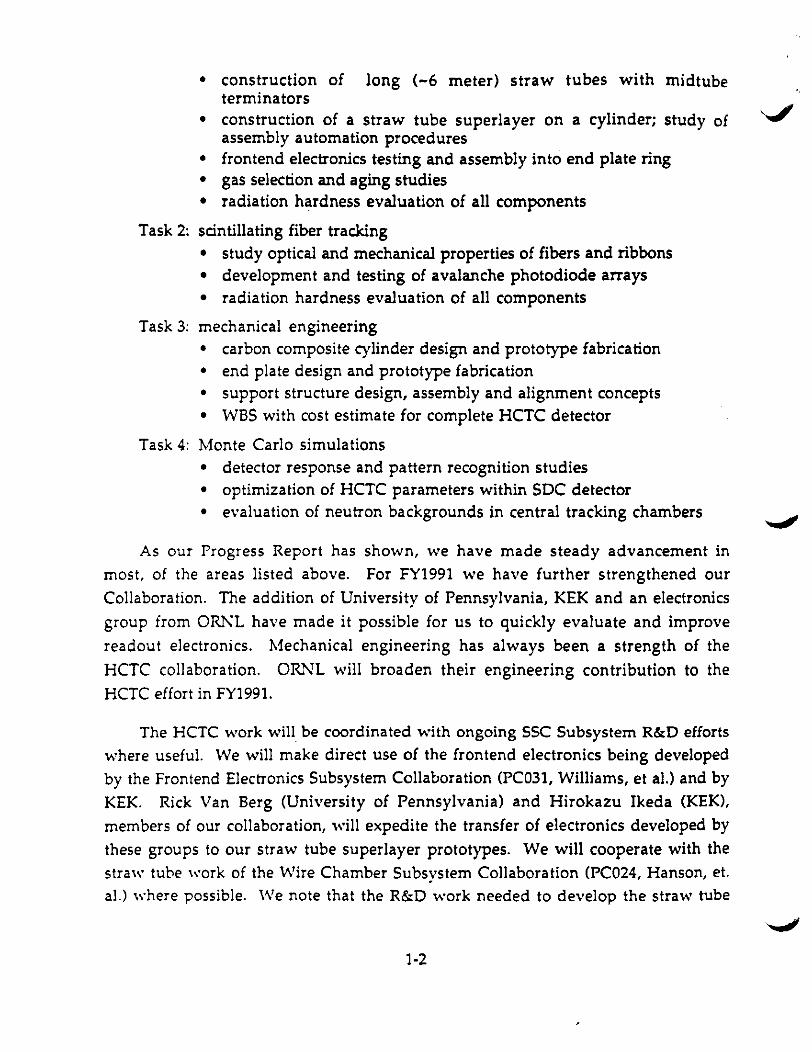
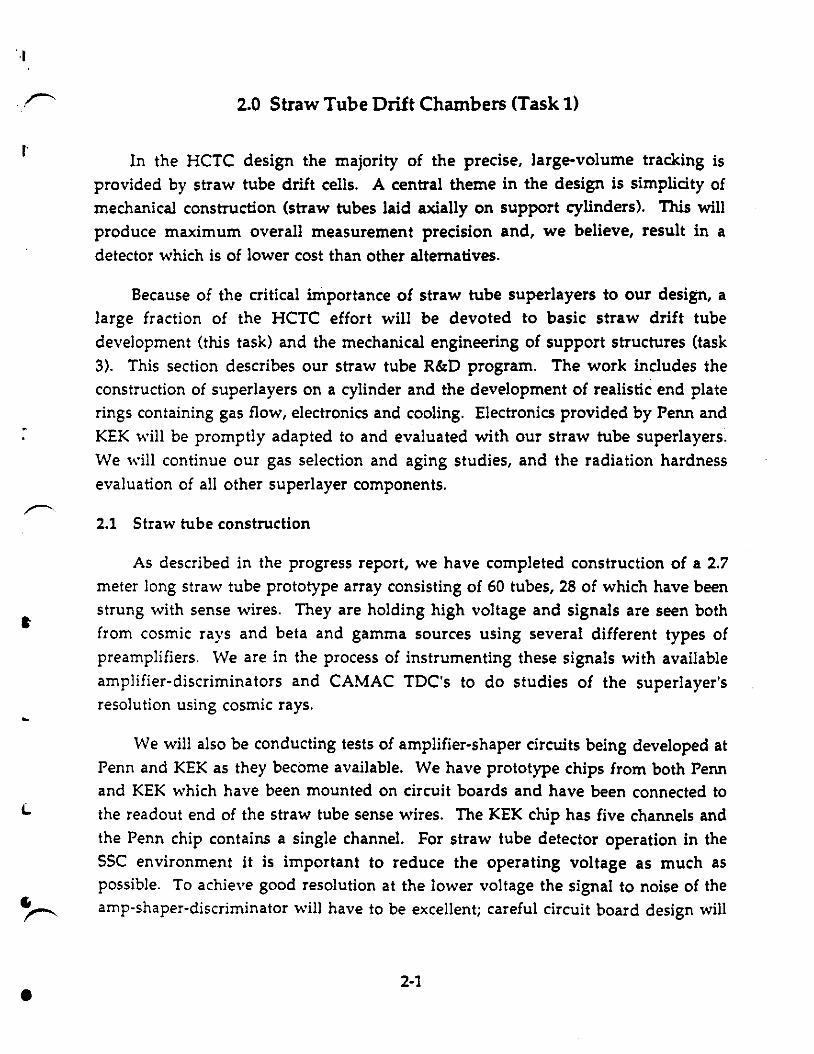
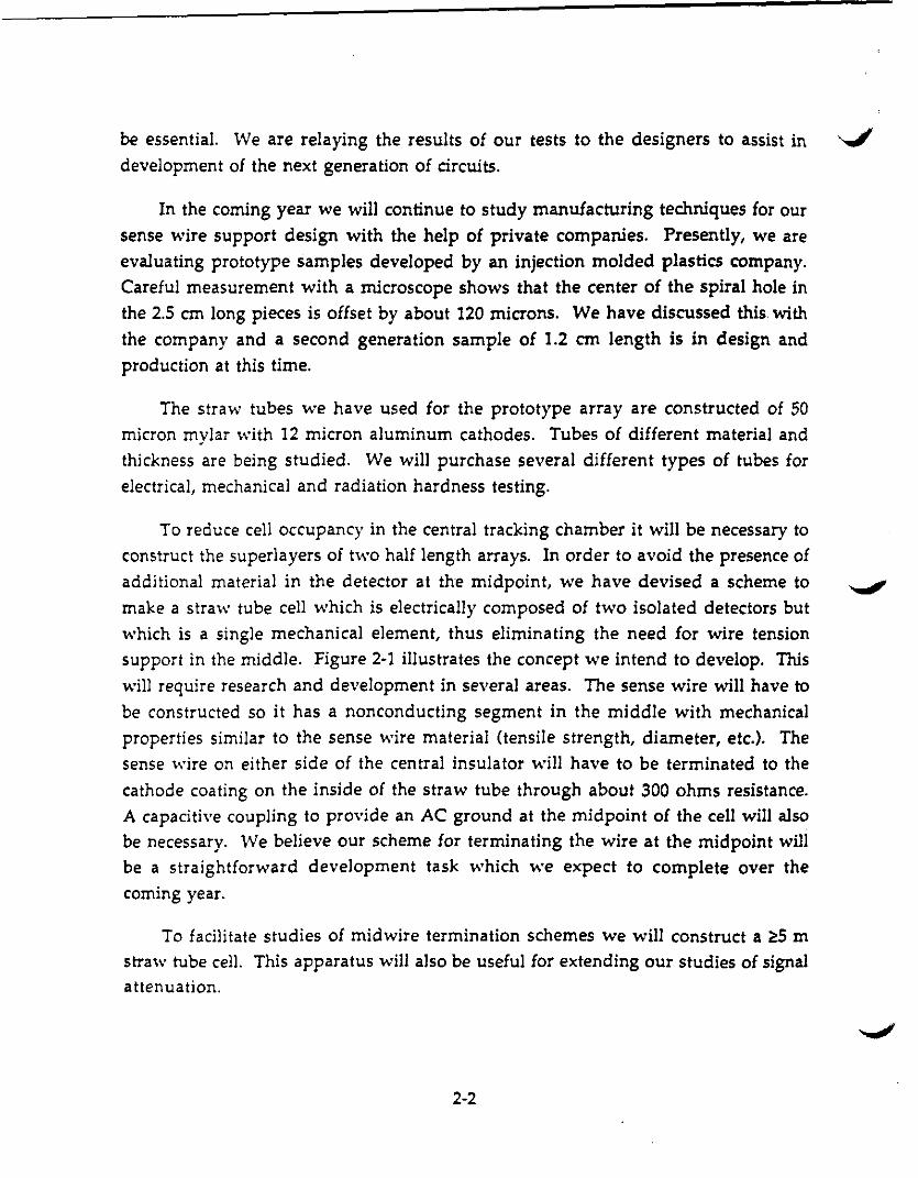
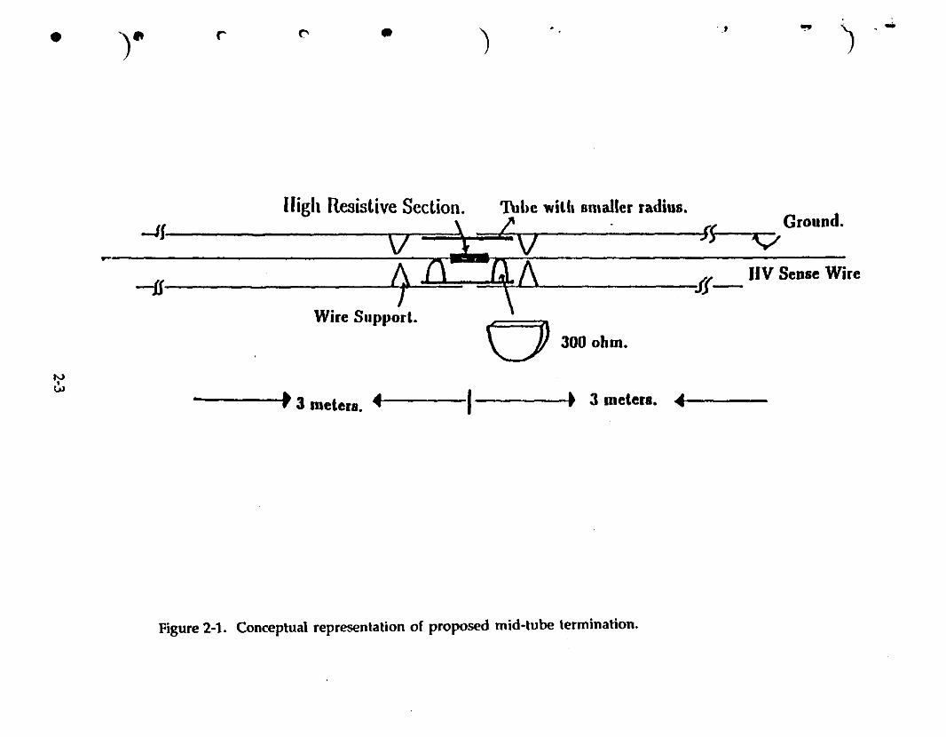
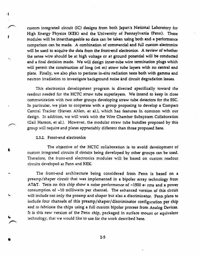
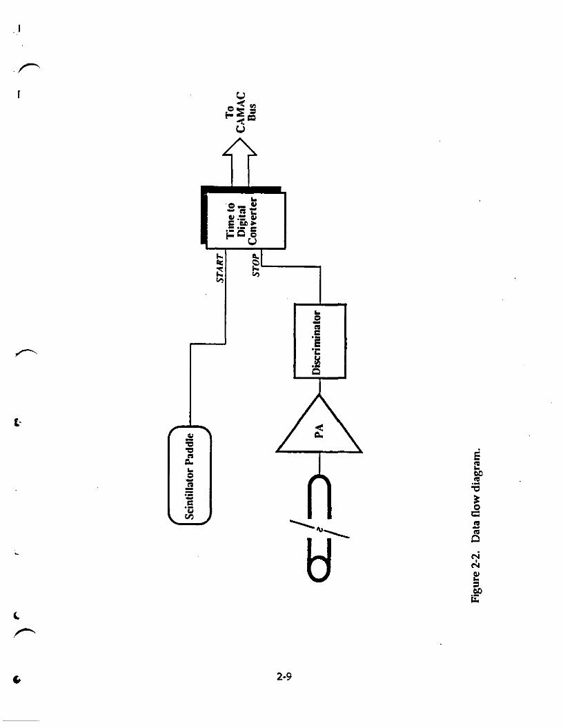
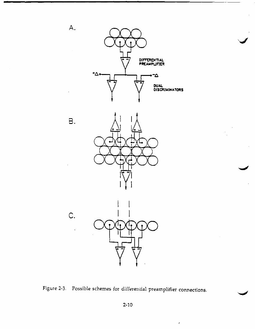
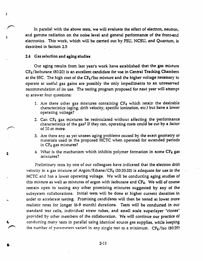
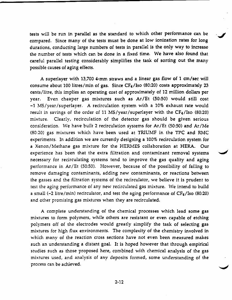


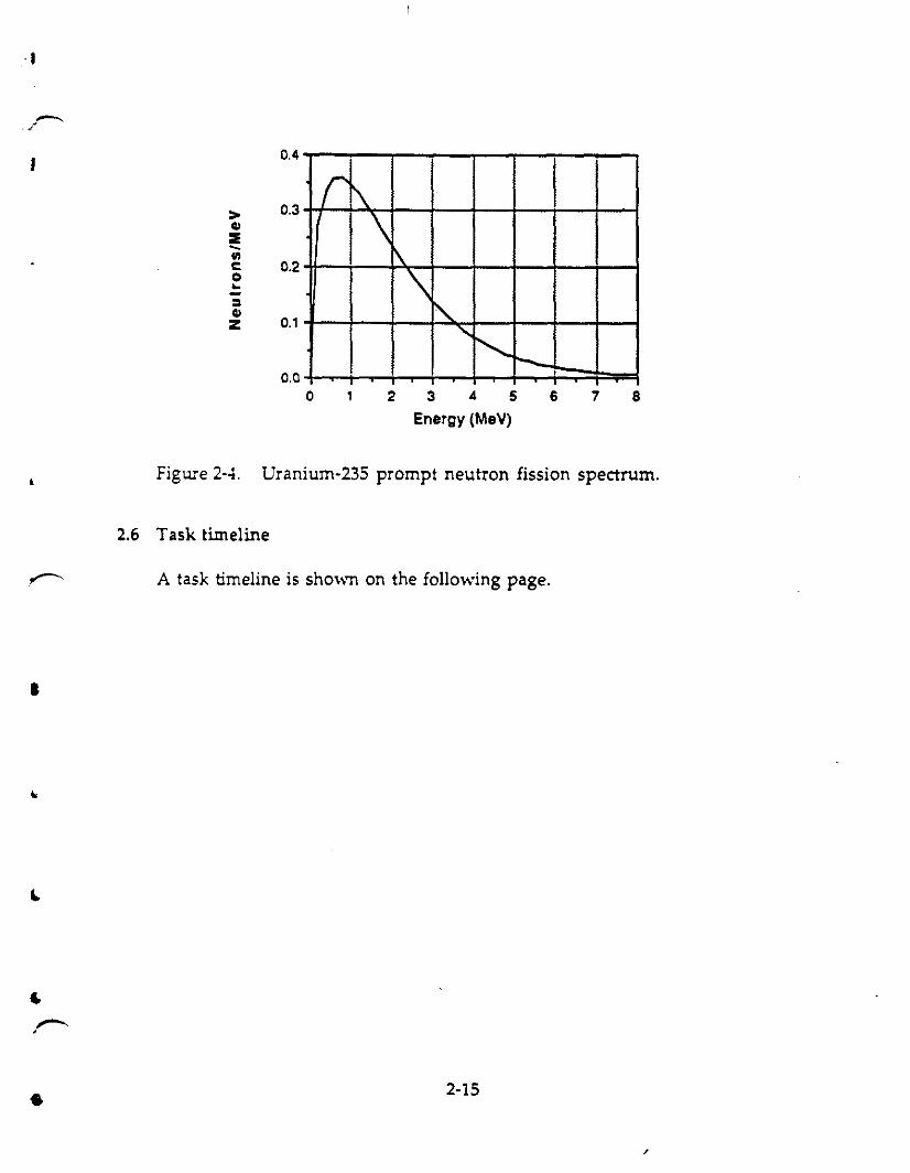
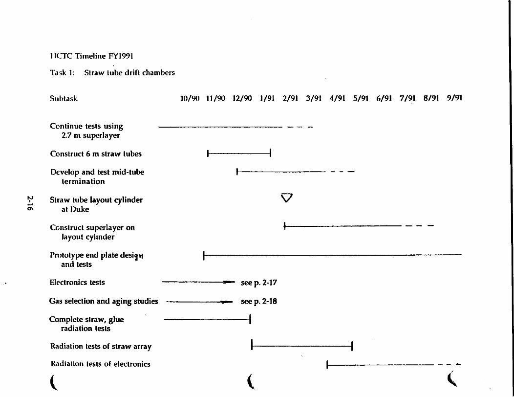

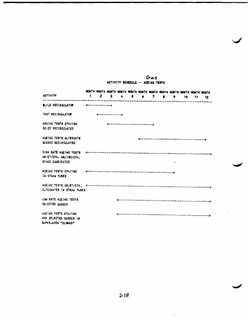
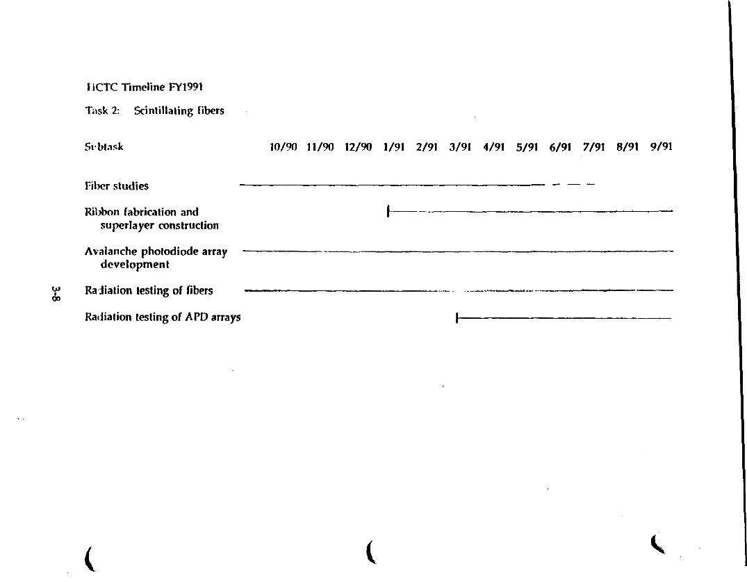
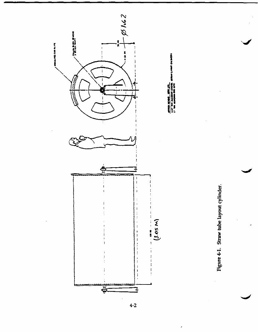
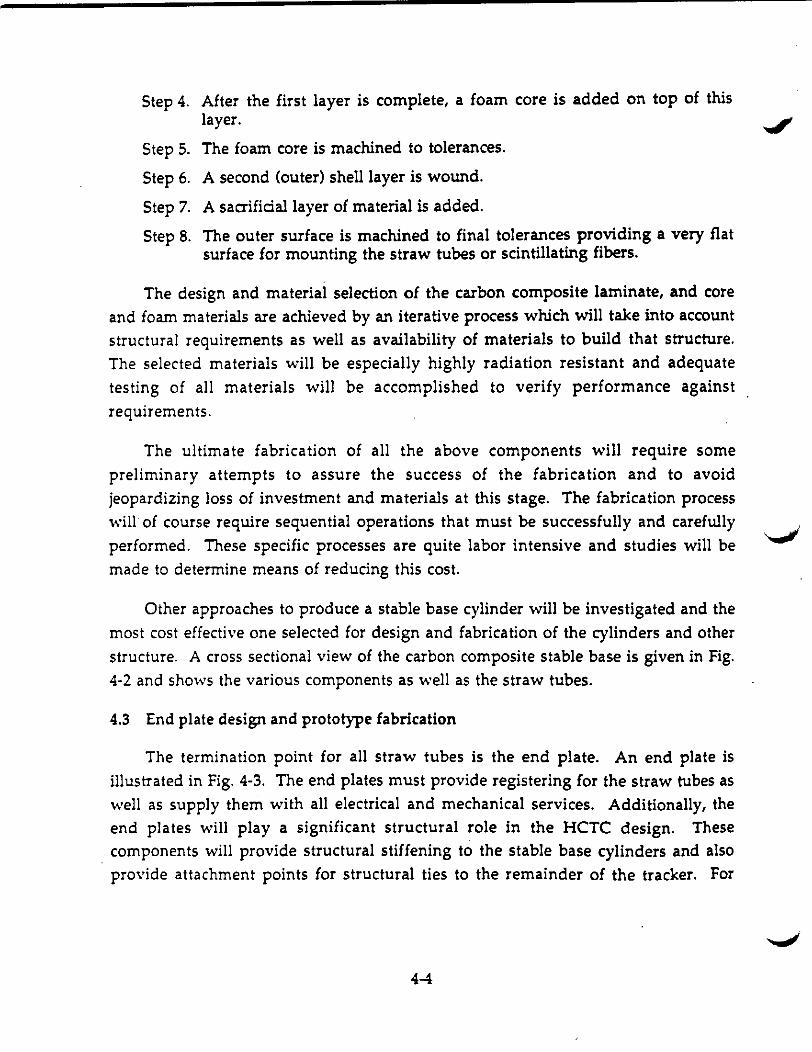
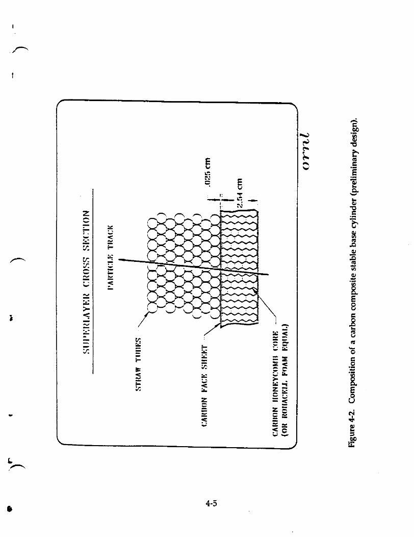
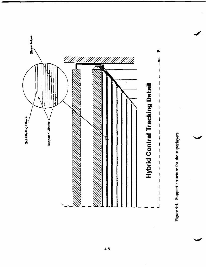
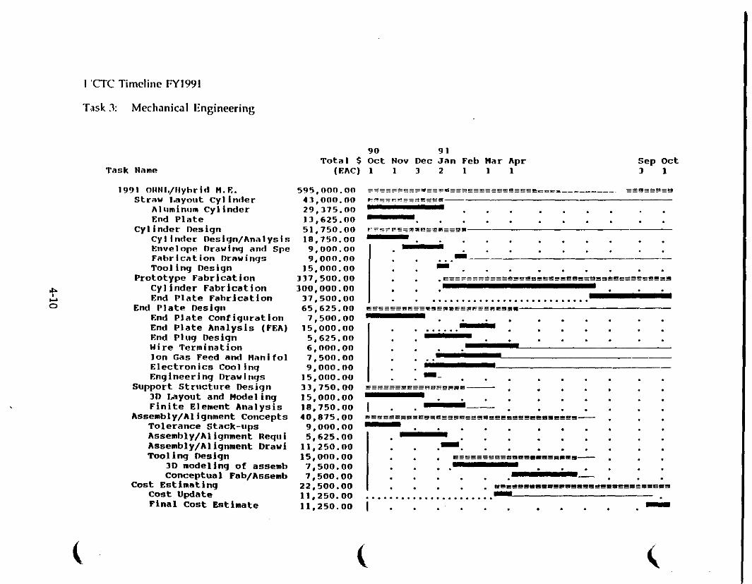
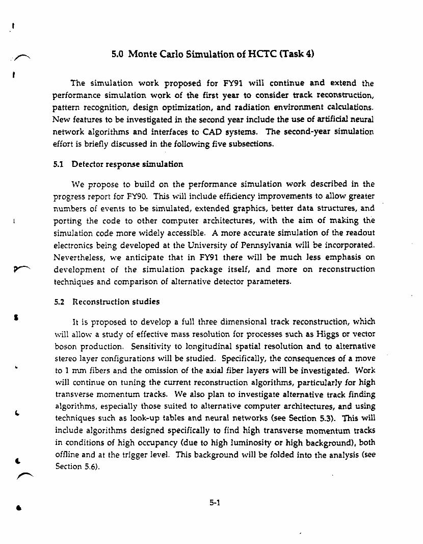
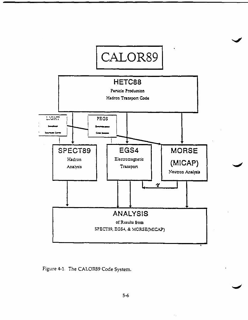


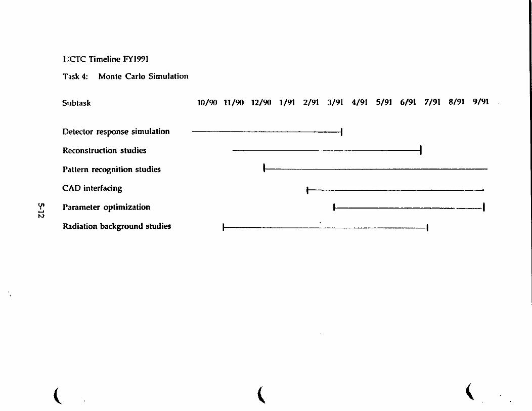
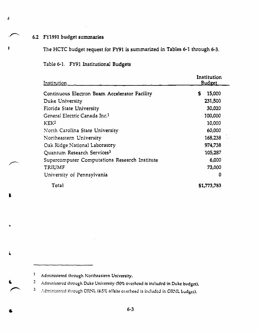
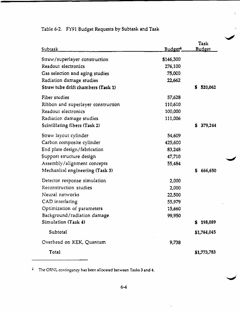
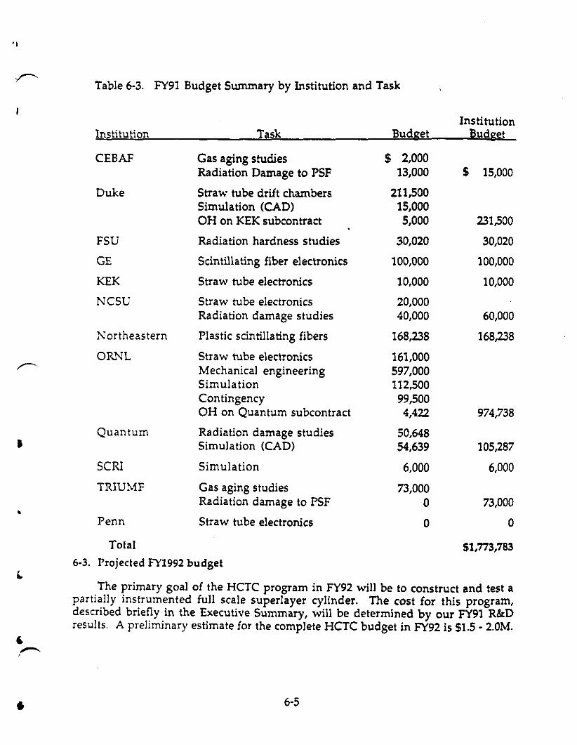


![Untitled3 [lss.fnal.gov]lss.fnal.gov/archive/other/sdc/sdc-90-151.pdf · 2009. 8. 12. · SD~-'tO-OO,s-l Or Letter of Intent OT by the SOLENOIDAL DETECTOR COLLABORATION to construct](https://static.documents.pub/doc/80x56/5fd2004678236530e445a345/untitled3-lssfnalgovlssfnalgovarchiveothersdcsdc-90-151pdf-2009-8.jpg)