1 Liu JL, Zhu S, Xu YL and Zhang Y (2011) Displacement-based design approach for highway bridges with SMA isolators. Smart Structures and Systems. 8(2): 173-190. This is the Pre-Published Version.
Transcript
1
Liu JL, Zhu S, Xu YL and Zhang Y (2011) Displacement-based design approach for highway bridges with SMA isolators. Smart Structures and Systems. 8(2): 173-190.
This is the Pre-Published Version.
2
Displacement-based design approach for highway bridges
with SMA isolators Jin-long Liu1,2, Songye Zhu*1, You-lin Xu1 and Yunfeng Zhang3
1Department of Civil and Structural Engineering, The Hong Kong Polytechnic University, Hung Hom, Kowloon,
Hong Kong, China 2Institute of Engineering Mechanics, China Earthquake Administration, Harbin 150080, China
3Department of Civil and Environmental Engineering, University of Maryland, College Park, MD, USA Abstract: As a practical and effective seismic resisting technology, the base isolation system has seen
extensive applications in buildings and bridges. However, a few problems associated with conventional
lead-rubber bearing have been identified after historical strong earthquakes, e.g. excessive permanent
deformations of bearings and potential unseating of bridge decks. Recently the applications of shape memory
alloys (SMA) have received growing interest in the area of seismic response mitigation. As a result, a variety
of SMA-based base isolators have been developed. These novel isolators often lead to minimal permanent
deformations due to the self-centering feature of SMA materials.
However, a rational design approach is still missing because of the fact that conventional design method
cannot be directly applied to these novel devices. In light of this limitation, a displacement-based design
approach for highway bridges with SMA isolators is proposed in this paper. Nonlinear response spectra,
derived from typical hysteretic models for SMA, are employed in the design procedure. SMA isolators and
bridge piers are designed according to the prescribed performance objectives. A prototype reinforced concrete
(RC) highway bridge is designed using the proposed design approach. Nonlinear dynamic analyses for
different seismic intensity levels are carried out using a computer program called “OpenSees”. The efficacy of
the displacement-based design approach is validated by numerical simulations. Results indicate that a properly
designed RC highway bridge with novel SMA isolators may achieve minor damage and minimal residual
deformations under frequent and rare earthquakes. Nonlinear static analysis is also carried out to investigate
the failure mechanism and the self-centering ability of the designed highway bridge.
‘yield’ stress), phase transformation finish strain εM and energy dissipation coefficient β (as shown in Fig. 1).
The parameters are tuned according to the stress-strain relationship of Nitinol wires produced by Johnson
Matthey Inc. (2010) when cyclically tested at the frequency of 2Hz:
EA = 39 GPa, EM = 19 GPa, σy = 390 MPa, α = 0.036, εM =0.062, β = 0.4
An apparent strain hardening can be observed at large strain, to which attention should be paid because of the
potential overloading to adjacent members. The fracture strain of Nitinol wires is over 14%. According to
(Zhang and Zhu, 2008), although the flag-shaped constitutive model could not accurately simulate the
unloading path, and does not reflect the loading rate effect, it can predict the seismic response with
satisfactory accuracy with regard to peak displacements, accelerations and ductility ratios in both SDOF
6
systems and MDOF systems, as far as its parameters are tuned to dynamic test data.
To enable the dynamic analysis of highway bridges with SMA devices, this constitutive model has been
implemented in the computer program OpenSees (Mazzoni et al. 2006) as a new material model.
2.2 SMA base isolator
A few SMA-based isolation systems have been developed and investigated by different researchers (Wilde,
et al. 2000, Choi, et al. 2005, Dolce et al. 2007, Casciati et al. 2007). A common feature of these isolators is
self-centering (also called re-centering) capability due to the superelastic behavior of Nitinol alloys or other
SMAs. Fig. 2(a) shows a scheme of a highway bridge isolation system, in which SMA elements are used
together with elastomeric bearings (or sliding bearings). The lateral stiffness and capacity of elastomeric
bearings are often much smaller than those of SMA elements (Wilde, et al. 2000). Therefore the elastomeric
bearings are treated as gravity load transfer elements in this study, while the lateral seismic load resistance is
mainly offered by SMA cables. The SMA cables are assumed to undertake tensile force only. It should be
noted that the schematic drawing shows a general model of some common SMA base isolators, and it may not
necessarily be a real configuration to be implemented in real bridges. The DBD approach presented in this
study can be easily adapted to aforementioned SMA isolators with similar hysteresis. Although only the
longitudinal SMA cables are shown in Fig. 2(a), similar elements should also be arranged in transversal
direction in real bridges.
2.3 Equivalent SDOF system of a highway bridge with SMA isolators
In DBD approach, it is assumed that seismic response of structures is often dominated by the fundamental
vibration mode so that it can be modelled by an equivalent SDOF system. Fig. 2(b) shows a simplified model
of the highway bridge with isolators, where kp, kb and ks represent the stiffness of the bridge pier, elastomeric
7
bearing and SMA isolator respectively. As mentioned before, the spring kb only provides vertical stiffness,
and their contribution to the overall lateral stiffness of the bridge is neglected. Therefore, the bridge can be
further simplified as an equivalent nonlinear SDOF system shown in Fig. 2(c) when subject to horizontal
ground motions in longitudinal direction, where u1 and u2 stand for the longitudinal displacement at the deck
level and the pier top level respectively, f12(t) represent the seismic force applied on the deck, and m is seismic
tributary mass to each bridge pier. The total mass of the superstructure is concentrated at deck level, and the
mass of the pier is not considered in the design process according to the study by Turkington et al (1989a,
1989b). The isolators between bridge piers and decks are often used to protect the concrete piers from
significant damage. Therefore it is always desirable to design the capacity of the bridge piers higher than the
‘yield load’ of the SMA isolators. Consequently, the system shown in Fig. 2(c) can be approximated by a
nearly linear spring in series with a nonlinear spring with flag-shaped hysteresis. As shown in Fig. 3(c), the
consequent hysteresis is still in a flag shape, however, the stiffness and ductility of the equivalent system is
different from those of the SMA materials. Easy to know that the yield displacement and the maximum
displacement of the equivalent system is
yp
ys
yeq uuu += (1)
mp
ms
meq uuu += (2)
where yequ ,,
ysu , y
pu are, respectively, the yield displacement of the system, the yield displacement of the SMA
isolator, and the top displacement of the pier corresponding to the yielding of the isolators; while
mequ , m
su , mpu is the maximum displacement of equivalent system, SMA isolator, and the top of the bridge pier.
The elastic stiffness and the post-yield stiffness ratio of the SMA isolator are ks and α, and its ductility is
defined as
ys
ms
uu
=μ (3)
8
Therefore the ductility, elastic stiffness and post-yield stiffness ratio of the equivalent system can be computed
as follows
yp
ys
mp
ms
yeq
meq
eq uuuu
uu
+
+==μ (4)
sp
pseq kk
kkk
+= (5)
)1/()/1(
)( +
+=
+=
ps
ps
eqps
pseq kk
kkkkk
kkαα
αα
α (6)
μeq, keq and αeq are not equal to μ, ks and α unless kp is infinite.
2.4 Nonlinear SDOF response spectra
It is well known that the seismic response of the structures is substantially dependent on the nonlinear
hysteretic behavior. Nonlinear response spectra of SDOF system with various hysteretic models have been
extensively studied (Newmark and Hall 1982, Nassar and Krawinkler 1991, Vidic, et al. 1994, Seo and Sause
1995). This section studies the nonlinear response spectra of SDOF system, in which a flag-shaped hysteresis
showing strain hardening at large strain is used. The hysteretic model is described in Fig. 3. The derived
nonlinear response spectra will be employed in DBD approach presented in the next section. Three major
parameters are considered in the nonlinear response spectra, namely the initial period T0 (from 0.2 to 3
seconds), the post-yield stiffness α ( 0.4 0.3, 0.2, 0.1, 0,= ) and the strength reduction factor R
(=1,2,3,4,5,6,7,8). T0 and R could be calculated by
eqkmT /20 π= (7)
ye FFR /= (8)
where keq is the initial stiffness of the SDOF system, Fe is the elastic design strength and Fy is the ‘yield’
strength of the equivalent nonlinear system.
9
A ground motion suite containing a total of 20 earthquake records, designated as EQ01-EQ20, is employed
in the computation. These 20 ground motions were derived from ten earthquakes, each comprising two
perpendicular components. They are scaled to match the seismic design spectrum of rare earthquake level for
seismic intensity level of 7.5 and site class II specified in Chinese seismic design code (2001) using the
scaling method proposed by Zhu and Gao (2009). Fig. 4 shows the design spectrum, and the response spectra
of the 20 scaled records. It is seen that the median spectrum can well match the design spectrum within the
period range of interest.
Fig. 5 shows the median spectra of ductility response, for varying parameters T0, α and R. Seo (2005)
emphasized the median response as the likely response for a set of ground motions based on the assumption
that nonlinear response follows a lognormal distribution. Furthermore, Seo (2005) proposed a regression
function to fit the nonlinear μ-R-T0 relationship of SDOF system for different types of hysteresis:
)/1exp(0
20),,(cTc
eq RRT =αμ (9)
where eqμ is the regression value of ductility, T0 is the initial period, R is the strength reduction factor, c1 and
c2 are functions of post-yield stiffness ratio α, with
21 )()( αα bac −= , 2
2 )()( αα dcc −= (10)
It can be seen that the relationship is characterized by four parameters a, b, c, d. This regression function is
also adopted in this study to simulate the nonlinear response spectra corresponding to hysteretic behavior of
SMA. Through regression analysis, the four parameters in this paper are taken as a = 0.408, b= 0.904, c = 0.98,
d = -0.37. The simulation results of the nonlinear response spectra are also shown in Fig. 5. It can be seen that
the regression function can well match the median spectra of the ductility over the period range of interest.
Consequently the force reduction factor can be expressed as
)/1exp(0
20),,(cTc
eqeqTR −= μαμ (11)
10
3. DBD approach
DBD approach has been developed and applied by some researchers to the seismic design of different
structures (Kowalsky, et al. 1995, Kowalsky 2002, Priestley 1997, Priestley and Kowalsky 2000, Lin et al.
2003, Medhekar and Kennedy 2000). In conventional DBD approach, nonlinear structure systems are usually
modeled by an equivalent linear system with equivalent elastic stiffness and equivalent viscous damping.
Chopra and Goel (2000, 2001) revised this approach by incorporating nonlinear design spectra in order to
improve the accuracy of the performance prediction. In this study, the DBD approach using nonlinear design
spectra is further extended to the design of highway bridges with SMA base isolators. The objective is to
design a highway bridge with SMA isolators in order to achieve the target performance level under given
intensity of ground motions, e.g. the maximum displacement, ductility and damage extent. The following
assumptions are made within the DBD procedure: the vibration of the isolated highway bridge is dominated
by the first mode and the mode shape is maintained during the earthquake; the lateral strength of the piers are
higher than the yield load of the SMA isolators so that the seismic behavior of the piers is almost linear; the
mass of the pier is relative small and can be ignored in comparison with that of the deck; all piers of the
highway bridge have the same height. As the elastomeric bearing provides only gravity carrying capacity, its
design is not discussed hereinafter. The design procedure is elaborated as follows:
Step one: Target Seismic Performance
Once basic structural parameters (e.g. mass and height) are known, the target performance levels under
design earthquake level should be determined, including the peak displacement at the top of the pier mpu , the
relative displacement between the deck and the pier msu , and the maximum ductility of SMA elements μ .
The first one mpu determines the damage level of the bridge pier. In order to prevent the bridge pier from
significant damage and noticeable residual deformation after an earthquake, it is desirable to limit its drift
11
ratio to the elastic limit state.
The peak relative displacement msu should be determined by taking into account various factors such as the
impact between the deck and the abutment, the potential unseating of bridge decks, the damage of joint
connections and the deformation capacity of elastomeric bearings. According to Zhang and Zhu (2008), SMA
cannot be fully recovered to its original shape after being loaded beyond 8% of strain, and thus partially loses
its self-centering capability. Therefore the ductility level of SMA has to be limited if minimal residual
displacement after an earthquake is desired.
Step two: Equivalent SDOF System
The peak displacement of the bridge deck can be easily estimated from Eq. (2). The restoring forces of SMA
base isolators can be calculated by
yss
ys ukF = (12)
yss
yss
ms ukukF )1( −+= μα (13)
where ysF and m
sF are respectively the yield force and peak forces of the isolators respectively. Meanwhile,
the piers are in elastic state under considered seismic level. As the piers are in series with the SMA isolators,
the resisting forces are always equal in these two elements.
ypp
ys ukF = (14)
mpp
ms ukF = (15)
Therefore, the ratio of the lateral stiffness ps kk /=η can be calculated from Eqs (12)–(15). The ductility μeq
and the post yield stiffness ratio αeq of the simplified equivalent SDOF system can be subsequently computed
by
)]1(/[ ημ += ys
meqeq uu (16)
)1/()1( αηηαα ++=eq (17)
12
Step three: Nonlinear Design Spectrum
The elastic design spectra (including pseudo acceleration spectrum Sae and displacement spectrum Sde) can
be obtained from the design code. The nonlinear acceleration spectra Sa and the displacement spectra Sd can be
constructed by
RSTS aeeqeqa /),,( 0 =αμ (18)
RSTS deeqeqeqd /),,( 0 μαμ = (19)
where μeq and αeq are calculated from Eq. (16) and (17). Based on the target displacement of the bridge deck
mequ , the initial period T0 and the corresponding acceleration level Sa can be easily determined according to Fig.
6.
Step four: Design of Isolators and Bridge Piers
The yield load of the bridge isolator is equal to
ay
s SmF ⋅= (20)
The lateral stiffness of the equivalent SDOF system, the SMA isolator and the bridge pier can be computed by
20
2 /4 Tmkeq π= (21)
ηη /)1( += eqp kk (22)
ps kk η= (23)
Once the yield load, initial stiffness, peak deformation and ductility level of the isolators are determined, the
length and cross sectional area of the SMA elements can be computed. Subsequently, with the desired stiffness
and strength of the bridge piers, the cross section of RC piers can be designed. In order to protect the pier from
significant damage, the bridge pier is typically designed to have a greater lateral strength than the yield load of
the SMA isolators.
Step five: Check Seismic Performance
13
The seismic performance levels of the designed highway bridge needs to be checked through nonlinear
static analyses and time-history analyses, particularly under other seismic intensity levels that are not
considered in the design procedure.
4. Case study
4.1 Design example
The example consists of a four-span RC highway bridge with three six-meter high piers and two rigid
abutments, as shown in Fig. 7. The bridge has four 20 m continuous spans, and the width of deck is 12 m. The
total mass of the superstructure is about 2000 ton. All the piers and the deck are reinforced concrete members.
The material properties of SMA are shown in section 2.1. According to the Chinese seismic design code
(2001), the bridge is designed for site class II and intensity level 7.5 with the peak ground acceleration of
0.31g (rare earthquake). The site classification in Chinese seismic design code is presented in Table 1. The
corresponding elastic design spectrum is shown in Fig. 4. The objective is to design the highway bridge with
target peak displacements and minimal residual deformation under the considered seismic intensity level. The
peak drift ratio of the piers is taken as 1/600 (i.e. mpu =1cm), and the ductility of SMA elements are taken as
μ=6. The peak displacement of the bridge deck is selected to be 12 cm based on the study by other researchers
on highway bridges (Choi, et al. 2005, Dolce, et al. 2007). Using the above-described design procedure, the
following structural parameters are determined: the length of SMA element 1830 =l cm; the cross-sectional
area of the SMA element in each isolator A=11.3 cm2; the effective width and height of the cross-section of
the pier b=1.8 m and h=1.1 m; a total of 18 steel bars with 25 mm diameter arranged along the width (one side)
of each pier.
In order to assess the efficacy of the proposed DBD approach, a finite element model of the designed bridge
is built using the computer program OpenSees (Mazzoni et al. 2006). The new material’s model is developed
14
in OpenSees to simulate the superelastic behavior of SMA. The pier and the deck are all simulated by
nonlinear beam-column elements with fiber sections. Nonlinear static analysis (i.e. pushover analysis) and
nonlinear time-history analyses are carried out in order to evaluate the seismic performance of the designed
highway bridge under different seismic intensity levels. Only the seismic ground motions in longitudinal
direction are considered.
4.2 Pushover analysis of the pier
A pushover analysis as defined by NEHRP recommendation provisions for seismic regulations for new
buildings and other structures (FEMA 450) (2003) is carried out to evaluate the failure mechanism and
self-centering capability of the isolated highway bridge. The pushover curves are shown in Fig. 8. Fig. 8(a)
illustrates the relationship between the total base shear of three piers and the deck displacement, in particular,
two unloading paths corresponding to medium deformation and large deformation of the SMA isolators are
indicated. The corresponding force-displacement relationship of the piers and SMA isolators are shown in Fig.
8(b). It is seen that the concrete piers crack at relative small displacement (point 1), and it results in a slight
reduction in the lateral stiffness of the bridge piers. Point 2 stands for the ‘yield’ load of the isolators, which is
actually due to stress-induced phase transformation of SMA instead of conventional yield mechanism. It
should be noted that the yield strength of the piers (point 4) is designed to have higher yield strength than the
yield load of the SMA isolators in order to effectively protect the piers from significant damage. Therefore the
pier behavior is nearly linear elastic when the isolator yields. As a result, the residual deformation of the
highway bridge will be ignorable when unloaded from the yield plateau (as shown by the unloading path a).
Point 3 represents the end of phase transformation, and obvious strain hardening can be observed after point 3.
The slope of the curve is governed by the modulus of elasticity of martensite SMA. The stain hardening
behavior of the SMA isolators results in a larger force exerted on the bridge piers. Consequently, the steel
15
reinforcement in the bridge pier begins to yield at point 4, and the system reaches its maximum capacity.
Further loading beyond point 4 leads to noticeable plastic deformation in the bridge piers. As shown by the
unloading path b, an apparent residual displacement can be observed in the bridge piers, even though the SMA
isolators can still recover their deformation, and the self-centering capability is partially lost. Therefore, if the
peak response is below point 1, there is no crack in concrete piers, both the bridge’s piers and isolators
behaves linearly, and the whole highway bridge is almost damage free; from point 1 to 4, the highway bridge
is only subjected to minor damage in the bridge piers without yielding of steel reinforcement and noticeable
residual displacement. This feature will considerably reduce the post-earthquake repair cost. However,
relatively large damage of the bridge pier may result from the strain hardening behavior of SMA at large
strain. It implies that neglecting the strain hardening behavior in the constitutive model of SMA may lead to
an underestimation of pier’s damage in seismic analyses.
4.3 Nonlinear dynamic analyses
The aforementioned twenty earthquake records are employed to investigate the actual seismic response of
the designed highway bridge. Following Chinese seismic design code (2001), the twenty ground motions are
scaled to match the design spectra of rare earthquakes (2-3% exceedance probability in 50 years) and frequent
earthquakes (63% exceedance probability in 50 years) respectively.
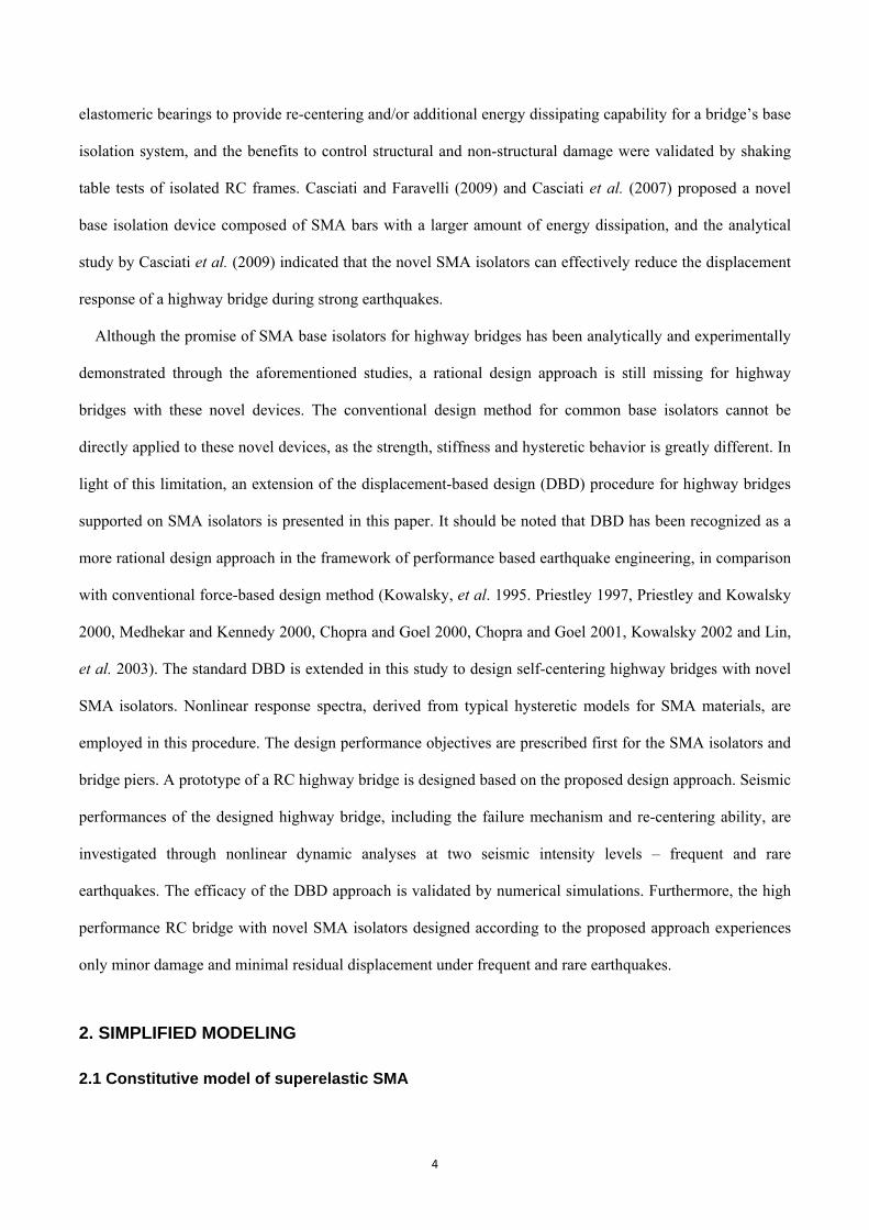
Figures 9-13 show the seismic response under the 20 rare earthquake records. The median values of the
peak displacements for the bridge pier, SMA isolators, and the bridge deck are 0.9 cm, 10.3 cm and 11.6 cm
respectively, which are close to the target displacements specified in the design procedure, namely 1.0 cm,
11.0 cm and 12.0 cm. The median ductility of SMA elements, i.e. 5.6, is close to the target value μ=6 as well.
In general, the proposed DBD approach is able to fairly well achieve the target displacement and ductility
specified in the design procedure.
16
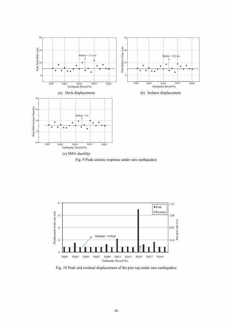
Fig. 10 shows the peak and residual displacements of the bridge pier for all 20 rare earthquake records.
Although the concrete piers tend to crack in all rare earthquakes, the bridge piers do not reach their yield
strength under 18 earthquake records. Furthermore, the residual displacement of the highway bridge is
ignorable under all the rare earthquakes except for EQ15. This clearly manifests the merit of the self-centering
feature of the SMA isolators. The limited damage in the bridge piers, together with nearly zero residual drift
ratios will considerably reduce the post-earthquake repair cost and effort. The results imply that highway
bridges with SMA isolators, if properly designed, are able to achieve a high seismic performance in
comparison with conventional bridge systems. The peak displacement is maximum under EQ15 among all 20
ground motions. The SMA isolators under EQ15 enter into the martensite range, and the strain hardening of
SMA at large deformation leads to an increased base shear. As a result, the bridge piers yield during EQ15,
and the plastic deformation of the bridge piers causes noticeable residual displacement after the earthquake.
These dynamic analysis results further justify the necessity of properly modeling the strain hardening at large
strain in the constitutive model of SMA. Figures 11-13 show the displacement time history of the pier, and the
force-displacement relationship of the piers and SMA isolators under EQ01 and EQ15. They provide further
supports to the above statements.
Fig. 14 shows the peak and residual displacements of the bridge pier under 20 frequent earthquake records.
The median value of the peak displacement is about 0.46 cm. No yielding of steel reinforcement occurs under
all the 20 records, and the bridge piers behave almost linearly. Consequently no apparent residual
displacement is observed after all the earthquakes. In around 15 earthquakes, the peak response of the bridge
is below point 1 shown in Figure 8, and the highway bridge is almost damage free without any cracks in the
bridge piers. The highway bridge is therefore associated with minor damages or even no damage after
frequent earthquakes.
17
5. Conclusion
In this paper, a displacement-based seismic design procedure for highway bridges supported on SMA
isolators is presented. Nonlinear response spectra derived from the constitutive model for SMA materials is
employed in the design procedure. A simplified SDOF model consisting of two springs in series is used to
represent the highway bridge. A four-span RC highway bridge is designed using the proposed design approach,
in which the major parameters of the bridge piers and SMA isolators are determined based on the desired
seismic performance objectives, including the target drift ratio of the bridge piers, target displacement of the
bridge deck and the target ductility of the SMA isolators.
A finite element model of the design example is built in OpenSees computer program. Nonlinear static and
time-history analyses are carried out to investigate its actual seismic behavior. The results indicate that the
simplified model can well predict the seismic response of the highway bridges of interest, and the proposed
DBD procedure can well achieve the target performance specified in the design procedure. Furthermore, the
highway bridges supported on SMA isolators, if properly designed, are associated with minor damage under
rare earthquakes, and are likely damage free under frequent earthquakes. The residual deformations after
earthquakes are minimal due to the superior self-centering feature of the SMA isolators. The high seismic
performance will considerably reduce the post-earthquake repair cost and the corresponding downtime. In
addition, both nonlinear static and dynamic analyses indicate that neglecting the strain hardening in the
constitutive model of SMA may result in an underestimation of seismic damage in the bridge’s piers.
It should be noted that the bridge piers are assumed to be of the same height, and the effect of vertical
ground motions are not considered in this study. Further development of this design procedure is needed in
future to appropriately address these two issues.
Acknowledgement
18
The authors are grateful for the financial support from The Hong Kong Polytechnic University through
research grant (PolyU-1-87SZ and PolyU-A-PJ15). Findings and opinions expressed here, however, are those
of the authors alone, not necessarily the views of the sponsoring agencies.
References
Andrawes B., and DesRoches R. (2005), “Unseating prevention for multiple frame bridges using superelastic devices”, Smart Materials and Structures, 14:S60-S67.
Casciati F., and Faravelli L. (2009), “A passive control device with SMA components: from the prototype to the model”, Structural Control and Health Monitoring, 16: 751-765.
Casciati F., Faravelli L., and Hamdaoui K. (2007), “Performance of a base isolator with shape memory alloy bars”, Earthquake Engineering and Engineering Vibration, 6(4):401-408.
Casciati F., Faravelli L. and Al Saleh R. (2009), “An SMA passive device proposed within the highway bridge benchmark”, Structural Control and Health Monitoring, 16(6): 657-667.
Chang K.C., Chang D.W., Tsai M.H. and Sun Y.C. (2000), “Seismic performance of highway bridges”, Earthquake Engineering and Engineering Seismology, 2(1):55-77.
Choi E., Nam T.H., and Cho B.S. (2005), “A new concept of isolation bearings for highway steel bridges using shape memory alloys”, Can. J. Civ. Eng., 32(5): 957-967.
Chopra A.K., and Goel R.K. (2000), “Evaluation of a NSP to estimate seismic deformation: SDF system”, Journal of Structural Engineering (ASCE), 126(4):482-490.
Chopra A.K., and Goel R.K. (2001), “Direct displacement-based design: use of inelastic vs. elastic design spectra”, Earthquake Spectra, 17(1):47-64.
Christopoulos C., Filiatrault A., and Folz B. (2002), “Seismic response of self-centering hysteretic SDOF systems”, Earthquake Engineering and Structural Dynamics, 31:1131-1150.
Dolce, M., Cardone, D. and Palermo G. (2007), “Seismic isolation of bridges using isolation systems based on flat sliding bearings”, Bull Earthquake Eng, 5:491-509
Graesser E.J., and Cozzarelli F.A. (1991), “Shape memory alloys as new materials for aseismic isolation”, Journal of Engineering Mechanics (ASCE), 117(11):2590-2608.
Hameed A., Koo M.S., Dai Do T.D., and Jeong J.H. (2008), “Effect of lead rubber bearing characteristics on the response of seismic-isolated bridges”, KSCE Journal of Civil Engineering, 12(3):187-196.
Han Q., Du X.L., Liu J.B., Li Z.X, Li L.Y. and Zhao J.F. (2009), “Seismic damage of highway bridges during the 2008 Wenchuan earthquake”, Earthquake Engineering and Engineering Vibration, 8:263-273.
Jankowski, R., Wilde, K. and Fujino, Y. (1998), “Pounding of superstructure segments in isolated elevated bridge during earthquakes”, Earthquake Engineering and Structural Dynamics, 27:487-502.
Johnson Matthey, Inc (2010) www.jmmedical.com Kowalsky M.J., Priestley M.J.N., and MacRae G.A. (1995), “Displacement-based design of RC bridge columns in
seismic regions”, Earthquake Engineering and Structural Dynamics, 24(12):1623-1643. Kowalsky M.J. (2002), “A displacement-based approach for the seismic design of continuous concrete bridges”,
Earthquake Engineering and Structural Dynamics, 31:719-747. Kwan W.P., and Billington S.L. (2003), “Unbonded Posttensioned Concrete Bridge Piers. I: Monotonic and Cyclic
Analyses”, Journal of Bridge Engineering (ASCE), 8(2):92-101. Lin Y.Y., Tsai M.H., Hwang J.S., and Chang K.C. (2003), “Direct displacement-based for buildings with passive energy
19
dissipation systems”, Engineer Structures, 25(1):25-37. Mazzoni, S., McKenna, F., Scott, M.H., Fenves, G.L. (2006) Open system for earthquake simulation user
command-language manual,, OpenSees version 1.7.3. Pacific Earthquake Engineering Research Center, University of California, Berkeley.
Medhekar M.S., and Kennedy D.J.L. (2000), “Displacement-based seismic design of buildings-theory”, Engineering Structures, 22:201-209.
Medhekar M.S., and Kennedy D.J.L. (2000), “Displacement-based seismic design of buildings-application”, Engineering Structures, 22:210-221.
Nassar A.A., and Krawinkler H. (1991), “Seismic damands for SDOF and MDOF systems”, Rep. No 95, John Blume Earthquake Engineering Center, Department of Civil Engineering, Stanford University, CA
National standard of the People’s Republic of China (2001). Code for seismic design of buildings (GB 50011-2001). Beijing; [in Chinese].
Newmark, N.M., and Hall, W.J. (1982), Earthquake spectra and design, Earthquake Engineering Research Institute, Berkeley, Calif.
Priestley, M. J. N. (1997), “Displacement-based seismic assessment of reinforced concrete buildings”, Journal of Earthquake Engineering, 1(1):157-192.
Priestley, M. J. N. (1997), “Myths and fallacies in earthquake engineering”, Concr. Int., 19(2): 54-63. Priestley M.J.N., and Kowasky M.J. (2000), “Direct displacement-based seismic of concrete buildings”, Bulletin of the
New Zealand National Society for Earthquake Engineering, 33(4):421-442. Seo, C.Y. and Sause, R. (2005), “Ductility demands on self-centering systems under earthquake loading”, ACI
Structural Journal. 102(2): 275-285. Seo C.Y. (2005), “Influence of ground motion characteristics and structural parameters on seismic response of SDOF
systems”, Ph.D dissertation, Lehigh University. Song G., Ma N. and Li H. N. (2006), “Applications of shape memory alloys in civil structures,” Engineering Structures,
28: 1266-1274. Turkington D.H., Carr A.J., Cooke N., and Moss P.J. (1989a), “Seismic design of bridges on lead-rubber bearings”,
Journal of Structural Engineering (ASCE), 115(12):3000-3016. Turkington D.H., Carr A.J., Cooke N., and Moss P.J. (1989b), “Design method for bridges on lead-rubber bearings”,
Journal of Structural Engineering (ASCE), 115(12):3017-3030. U.S. building seismic safety council. (2003), NEHRP recommendation provisions for seismic regulations for new
buildings and other structures (FEMA 450). Vidic T., Fajfar P., and Fischinger M. (1994), “Consistent inelastic design spectra: strength and displacement”,
Earthquake Engineering and Structural Dynamics, 23:507-521. Wilde W., Gardoni P., and Fujino Y. (2000), “Base isolation system with shape memory alloy device for elevated
highway bridges”, Engineering Structures, 20:222-229 Wilson J.C. and Wesolowsky M.J. (2005), “Shape memory alloys for seismic response modification: a state-of-the-art
review”, Earthquake Spectra, 21(2): 569-601. Zhang Y.F., Camilleri J.A., and Zhu S.Y. (2008), “Mechanical properties of superelastic Cu-Al-Be wires at cold
temperatures for the seismic protection of bridges”, Smart Materials and Structures, 17, 025008 (9pp). Zhang Y., Hu X. and Zhu S. (2009), “Seismic performance of benchmark base isolated bridges with superelastic
Cu-Al-Be wire damper”, Structural Control and Health Monitoring, 16(6): 668-685. Zhang Y. and Zhu S. (2008), “Seismic resistant braced frame structures with shape memory alloy-based self-centering
damping device”. In: Miura, T., Ikeda, Y. (eds.): Earthquake Engineering: New Research, Nova Science Publisher, Inc., Hauppauge, USA, 219-254.
20
Zhang, Y. and Zhu, S. (2008), “Seismic response control of building structures with superelastic Shape Memory Alloy wire damper”, Journal of Engineering Mechanics( ASCE), 134(3): 240-251.
Zhu, S. and Gao, Y. (2009), “Genetic algorithm-based development of ground motion time histories”. Proceedings of 2009 ANCER Workshop, University of Illinois Urbana-Champaign, IL, USA, August 13-14.
Zhu S. and Zhang Y. (2008), “Seismic analysis of concentrically braced frame systems with self-centering friction damping braces”, Journal of Structural Engineering (ASCE), 134(1): 121-131.
20
Figure list
Fig. 1 Constitutive model of superelastic SMA
Fig. 2 Simplified modelling of a highway bridges with SMA base isolators Fig. 3 Hysteretic behavior of the highway bridge with SMA isolators Fig. 4 Acceleration response spectra of 20 earthquake records considered Fig. 5 The median spectra of the ductility μeq for varying R and α
Fig. 6 Nonlinear displacement and acceleration spectra
Fig. 7 A four-span RC highway bridge with SMA base isolators
Fig. 8 Pushover analysis results of highway bridges with SMA isolators
Fig. 9 Peak seismic response under rare earthquakes
Fig. 10 Peak and residual displacement of the pier top under rare earthquakes
Fig. 11 Time history of pier top displacement under EQ01 and EQ15
Fig. 12 Lateral force-displacement relationship of bridge pier under EQ01 and EQ15
Fig. 13 Lateral force-displacement relationship of SMA isolator under EQ01 and EQ15
Fig. 14 Peak and residual displacement of the bridge pier under frequent earthquakes
21
Table 1. Site class definition for seismic design (China’s code for seismic design of buildings 2001)
Equivalent shear
wave velocity
(m/s)
Total thickness of overlaying
layers for each class* (m)
I II III IV
vse > 500 0
500 ≥ vse > 250 <5 ≥5
250 ≥ vse > 140 <3 3~50 >50
vse ≤ 140 <3 3~15 15~80 >80
* the thickness of overlaying layer is the distance measured from ground to underlying rock layer (i.e.
the layer with vse > 500 m/s)
22
0 0.02 0.04 0.06 0.080
300
600
900
ExperimentModel
ε
σ(M
Pa)
Austenite Phase transformation Martensite
EA
αEA
EM
σy βσy
Fig. 1 Constitutive model of superelastic SMA
Pier
Deck
SMA Cable
Elastomeric Bearingor Sliding Surface
m
kp
ks
kb
mkp k s
f
u1
u2
12(t)
(a) Schematic configuration of a highway bridge isolators
(b) modelling of an isolated highway bridge
(c) simplified modelling
Fig. 2 Simplified modelling of a highway bridges with SMA base isolators
kp
00
f
u2-u1
up
2 f
u1
1
0
f
u2
12
f s f p
keq
aks
(series)
aepkeq
ks
f ps
us ueqy ueq
my usm
(a) SMA isolator (b) Bridge pier (c) Equivalent system Fig. 3 Hysteretic behavior of the highway bridge with SMA isolators
23
0.0 0.5 1.0 1.5 2.0 2.50.0
0.4
0.8
1.2
1.6
Spec
tral A
ccel
erat
ion
(g)
Period Tn (sec)
Design spectrum of Chinese Code Median of 20 records Maxmum of 20 records Minmum of 20 records
Fig. 4 Acceleration response spectra of 20 earthquake records considered
0.0 0.5 1.0 1.5 2.0 2.5 3.00
4
8
12
16
20
α=0 α=0.1 α=0.2 α=0.3 α=0.4
α=0 α=0.1 α=0.2 α=0.3 α=0.4
μeq
Tn (sec)
R=3
0.0 0.5 1.0 1.5 2.0 2.5 3.00
4
8
12
16
20
R=4
μeq
Tn (sec)
α=0 α=0.1 α=0.2 α=0.3 α=0.4
α=0 α=0.1 α=0.2 α=0.3 α=0.4
(a) R=3 (b) R=4
0.0 0.5 1.0 1.5 2.0 2.5 3.00
4
8
12
16
20
R=5 α=0 α=0.1 α=0.2 α=0.3 α=0.4
α=0 α=0.1 α=0.2 α=0.3 α=0.4
Tn (sec)
μeq
0.0 0.5 1.0 1.5 2.0 2.5 3.00
4
8
12
16
20
μeq
Tn (sec)
R=6 α=0 α=0.1 α=0.2 α=0.3 α=0.4
α=0 α=0.1 α=0.2 α=0.3 α=0.4
(c) R=5 (d) R=6 Fig. 5 The median spectra of the ductility μeq for varying R and α
ω
regression median regression median
24
T0
mequ
Sa Sd
SaS
a (g
)
Sd(m
)
Period (sec)
Fig. 6 Nonlinear displacement and acceleration spectra
20m 20m 20m 20m
6m 6m6m
Fig. 7 A four-span RC highway bridge with SMA base isolators
25
-0.05 0.00 0.05 0.10 0.15 0.20 0.25-5.0x10⁵
0.0
5.0x10⁵
1.0x10⁶
1.5x10⁶
2.0x10⁶
2.5x10⁶
3.0x10⁶
SMA Yield b
a
5
4
32
1
Crack Residual displacement
SMA came into martensite
Yield of steel bars
Tota
l Bas
e Sh
ear (
N)
Deck Displacament (m)
(a) Base shear - deck displacement relationship
0.00 0.05 0.10 0.15 0.20
-1.0x10⁶
-5.0x10⁵
0.0
5.0x10⁵
1.0x10⁶
1.5x10⁶
2.0x10⁶
2.5x10⁶
3.0x10⁶
Pier SMA
Tota
l Bas
e Sh
ear (
N)
Displacament (m)
5
4
32
1
(b) Force-displacement relationship of the SMA isolators and piers Fig. 8 Pushover analysis results of highway bridges with SMA isolators
26
0
20
40
60
EQ20EQ15EQ10EQ05
Median = 11.2 cm
Peak
Dec
k D
isp.
(cm
)
Earthquake Record No.EQ01
0
20
40
60
EQ20EQ15EQ10EQ05
Median = 10.2 cm
Peak
Rel
ativ
e D
isp.
(cm
)
Earthquake Record No.EQ01
(a) Deck displacement (b) Isolator displacement
-10
0
10
20
30
Earthquake Record No.
Peak
SM
A Is
olat
or D
uctil
ity
Median = 5.6
EQ20EQ15EQ10EQ05EQ01
(c) SMA ductility Fig. 9 Peak seismic response under rare earthquakes
0
2
4
6
8
EQ01 EQ03 EQ05 EQ07 EQ09 EQ11 EQ13 EQ15 EQ17 EQ19
Dis
plac
emen
t at p
ier t
op (
cm)
Earthquake Record No.
Peak
Residual
Pier
drif
t rat
io (
%)
0.33
0.67
1.00
1.33
Midain = 0.9 cm
Fig. 10 Peak and residual displacement of the pier top under rare earthquakes
Median = 0.9cm
27
0 10 20 30 40 50 60-0.02
-0.01
0.00
0.01
0.02
Pier
Top
Dis
plac
emen
t (m
)
Time (sec)0 10 20 30 40 50 60
-0.02
0.00
0.02
0.04
0.06
0.08
Pier
Top
Dis
plac
emen
t (m
)
Time (sec)
(a) EQ01 (b) EQ15 Fig. 11 Time history of pier top displacement under EQ01 and EQ15
-0.04 -0.02 0.00 0.02 0.04 0.06 0.08
-1.0x10⁶
-5.0x10⁵
0.0
5.0x10⁵
1.0x10⁶
Bas
e Sh
ear (
N)
Displacement (m)
No Residual displacement
0
-0.04 -0.02 0.00 0.02 0.04 0.06 0.08 0.10
-1.0x10⁶
-5.0x10⁵
0.0
5.0x10⁵
1.0x10⁶
Bas
e Sh
ear (
N)
Displacement (m)
Residual displacement
0
(a) EQ01 (b) EQ15 Fig. 12 Lateral force-displacement relationship of bridge pier under EQ01 and EQ15
28
-0.2 -0.1 0.0 0.1 0.2-8.0x10⁵
-4.0x10⁵
0.0
4.0x10⁵
8.0x10⁵Fo
rce
(N)
Displacement (m) -0.2 -0.1 0.0 0.1 0.2
-1.0x10⁶
-5.0x10⁵
0.0
5.0x10⁵
1.0x10⁶
Forc
e (N
)
Displacement (m)
(a) EQ01 (b) EQ15 Fig. 13 Lateral force-displacement relationship of SMA isolator under EQ01 and EQ15
0
0.2
0.4
0.6
0.8
EQ01 EQ03 EQ05 EQ07 EQ09 EQ11 EQ13 EQ15 EQ17 EQ19
Dis
plac
emen
t at p
ier t
op (
cm)
Earthquake Record No.
Peak
Residual
Pier
drif
t rat
io (
%)
0.033
0.067
0.100
0.133
Midain = 0.46 cm
Fig. 14 Peak and residual displacement of the bridge pier under frequent earthquakes