Abu Dhabi University College of Engineering and Computer Science FALL 2014/2015 Structural Steel Design CIV413 Group #12 Term Project Submitted by : ID: Hakam Amer Ayyad 1028763 Alhareth Hamid 1029638 Saleh Khalaf 1025786 1
Transcript
Abu Dhabi University
College of Engineering and Computer Science
FALL 2014/2015
Structural Steel Design
CIV413
Group #12
Term Project
Submitted by: ID:
Hakam Amer Ayyad 1028763
Alhareth Hamid 1029638
Saleh Khalaf 1025786
Instructor: Dr. Zubair Sayed
1
Table of contents:
Title Page Number
Cover Page 1
Table of Contents 2
Introduction 3
Why we did our project 4
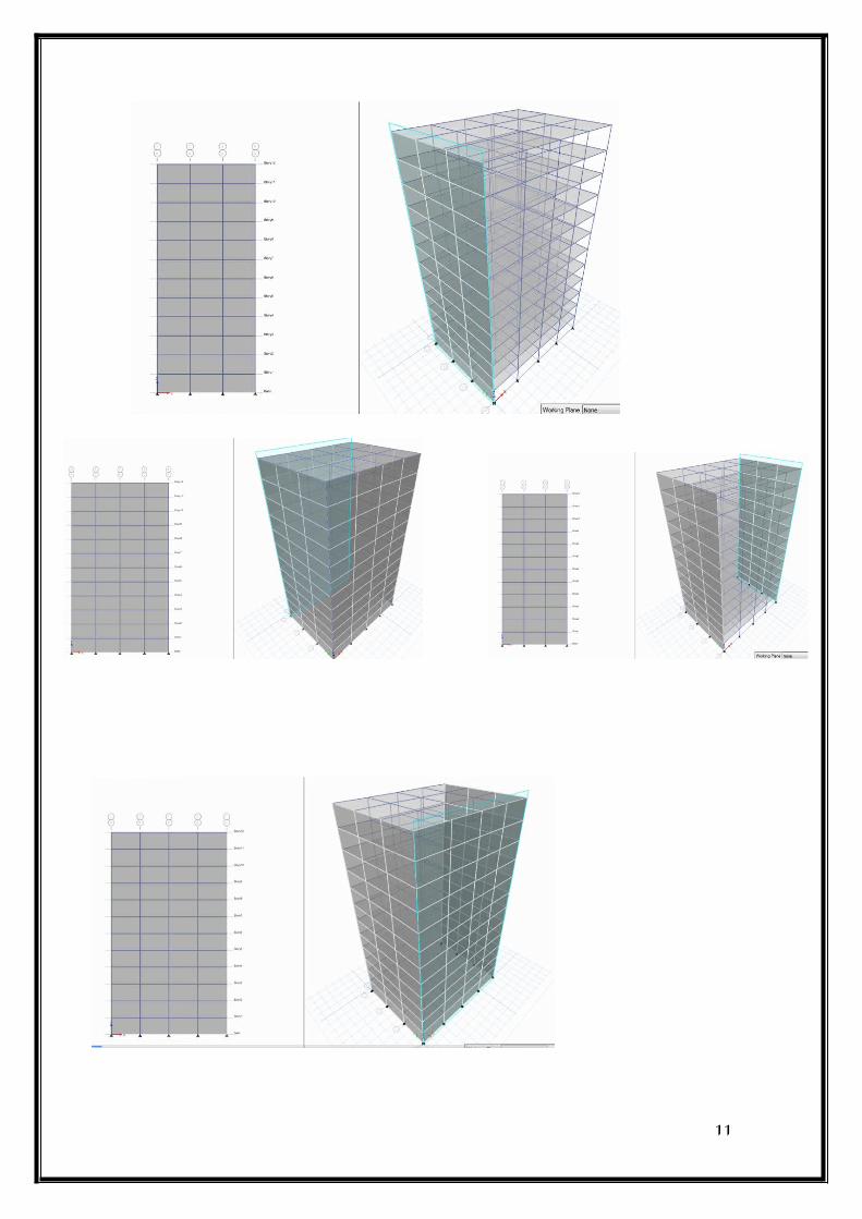
Step by step analysis of the project 4-12
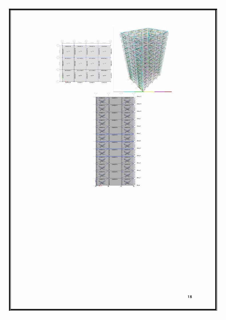
Running the analysis 13-18
Deflected shape of the building 19
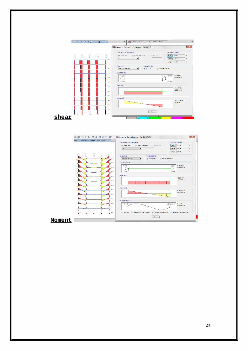
Axial, Shear and Moment diagrams for
Load combinations
20-26
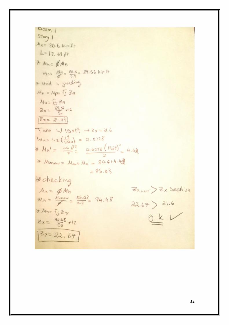
Manual Calculations
27-32
Conclusion 33
References 34
2
Introduction:
We as civil engineers know that steel plays a big part of our professional lives.
Steel is used in almost every building around the world. Why is that? Steel is popular
and it is one of the most important materials used in constructing that is because steel
has a very high tensile strength and is much cheaper than other materials with similar
properties. Steel is a mixture of carbon and iron.
Steels containing 0.2% C to 1.5% C are known as carbon steel. They are of three types. It contains 14% to 18% chromium and 7% to 9% nickel.The three types of carbon steel are :
1. Low carbon steel2. Mild carbon steel3. High carbon steel
The other types of steel are alloy steel and stainless steel.
Why use steel?
Steel is not only one of the strongest materials in the world today, it is
the best automotive material in terms of its design flexibility, cost
effectiveness, low emissions during manufacture, recyclability, and the list
could go on. The typical strength of steel is 50 ksi which is a lot higher than
other materials and it is much lighter as well.
Structural steel is steel construction material, a profile, formed with a
specific shape or cross section and certain standards of chemical composition and