63
Superconduttivita’ e Criogenia XXII Giornate di Studio sui Rivelatori Torino, 15 Giugno 2012 Amalia Ballarino European Organization for Nuclear Research (CERN), Geneva
Superconduttivita’ e Criogenia
XXII Giornate di Studio sui Rivelatori
Torino, 15 Giugno 2012
Amalia Ballarino
European Organization for Nuclear Research (CERN), Geneva

Introduction
Superconductivity for high energy physics
Part I
Cryogenics for LHC
Part II
Superconductivity in LHC
PART III
Superconductivity & Cryogenics in LHC Upgrades
Amalia Ballarino XXII Giornate di Studio sui Rivelatori
Amalia Ballarino XXII Giornate di Studio sui Rivelatori
Introduction
Superconductivity for high energy physics
Part I
Cryogenics for LHC
Part II
Superconductivity in LHC
PART III
Superconductivity & Cryogenics in LHC Upgrades
“In physics, cryogenics is the study of the production of very low eye temperature (below –150 °C, –238 °F or 123 K) and the behavior of materials at those temperatures” from Wikipedia The lowest natural temperature ever recorded on earth was in 1983 in Antartica: -89.2 oC or 183.8 K
What is cryogenics ?
What is superconductivity ?
“Superconductivity is a phenomenon occurring in certain materials at very low temperatures , characterized by exactly zero electrical resistance and the exclusion of the interior magnetic field (the Meissner effect) from Wikipedia
Cryogenic: for Greek “kryos", which means cold or freezing, and "genes" meaning born or produced.
Amalia Ballarino XXII Giornate di Studio sui Rivelatori
Introduction
Amalia Ballarino XXII Giornate di Studio sui Rivelatori
Introduction
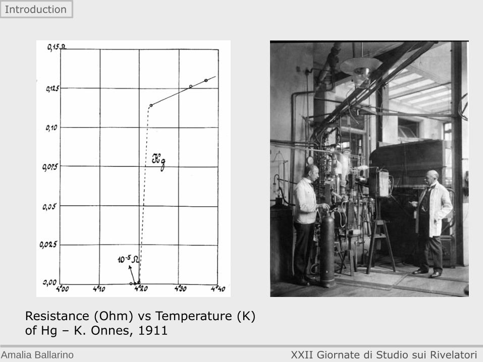
Resistance (Ohm) vs Temperature (K) of Hg – K. Onnes, 1911
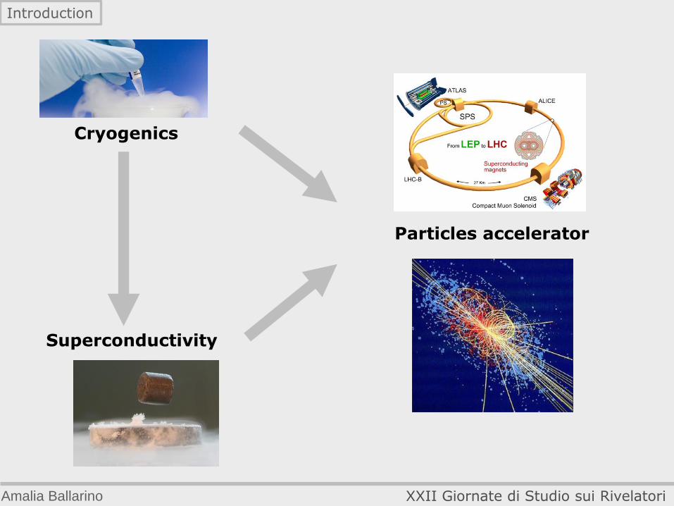
Cryogenics
Superconductivity
Particles accelerator
Amalia Ballarino XXII Giornate di Studio sui Rivelatori
Introduction
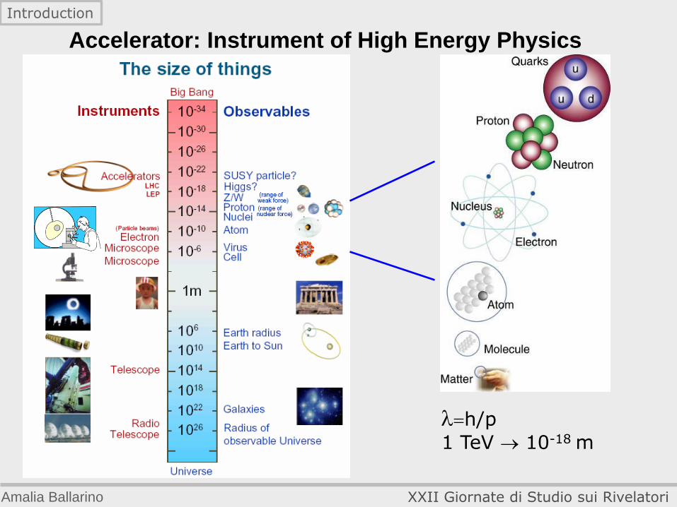
Accelerator: Instrument of High Energy Physics
h/p
1 TeV 10-18 m
Amalia Ballarino XXII Giornate di Studio sui Rivelatori
Introduction
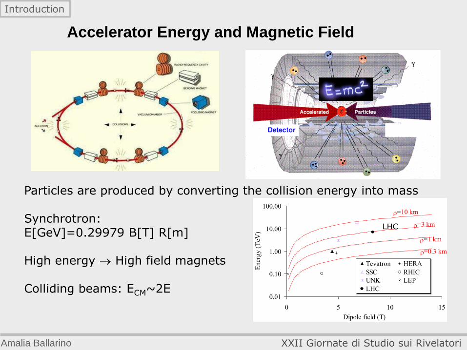
Particles are produced by converting the collision energy into mass Synchrotron: E[GeV]=0.29979 B[T] R[m] High energy High field magnets Colliding beams: ECM~2E
Accelerator Energy and Magnetic Field
Amalia Ballarino XXII Giornate di Studio sui Rivelatori
Introduction
0.01
0.10
1.00
10.00
100.00
0 5 10 15
Dipole field (T)
En
erg
y (
TeV
)Tevatron HERA
SSC RHIC
UNK LEP
LHC
r=10 km
r=3 km
r=1 km
r=0.3 km
LHC
Resistive magnets The most economical designs are iron-dominated; The upper field limit for iron-dominated magnets is ~2 T due to iron
saturation; Most resistive accelerator magnet rings are operated at low field (~
1 T), to limit power consumption ( B R).
Superconducting magnets
Significant reduction in power consumption (cryogenic power R); Higher current density in the magnet coils.
Amalia Ballarino XXII Giornate di Studio sui Rivelatori
Introduction
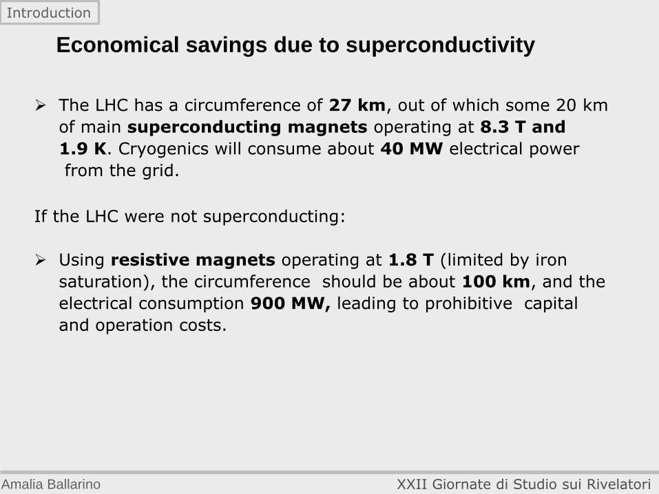
The LHC has a circumference of 27 km, out of which some 20 km
of main superconducting magnets operating at 8.3 T and
1.9 K. Cryogenics will consume about 40 MW electrical power
from the grid.
If the LHC were not superconducting:
Using resistive magnets operating at 1.8 T (limited by iron
saturation), the circumference should be about 100 km, and the
electrical consumption 900 MW, leading to prohibitive capital
and operation costs.
Economical savings due to superconductivity
Amalia Ballarino XXII Giornate di Studio sui Rivelatori
Introduction
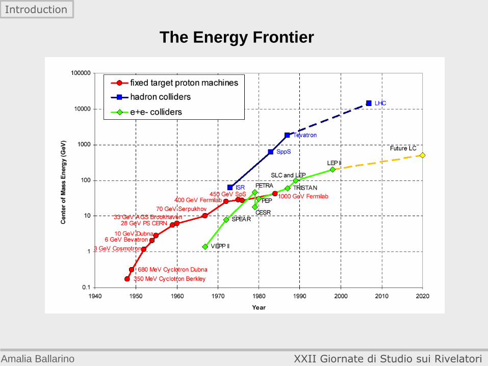
The Energy Frontier
Amalia Ballarino XXII Giornate di Studio sui Rivelatori
Introduction
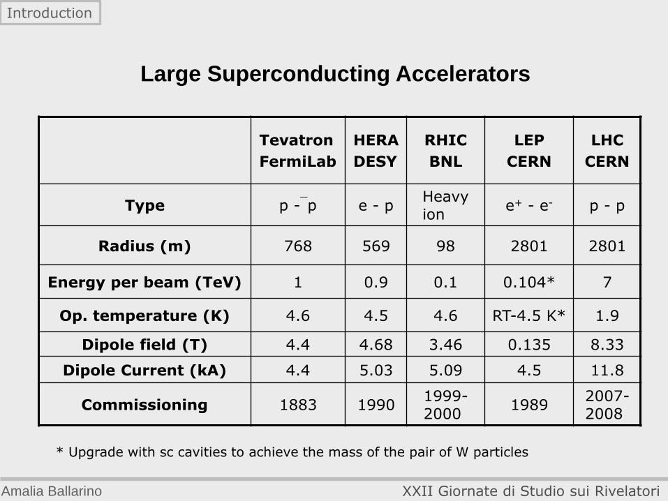
Tevatron
FermiLab
HERA
DESY
RHIC
BNL
LEP
CERN
LHC
CERN
Type p -p e - p Heavy ion
e+ - e- p - p
Radius (m) 768 569 98 2801 2801
Energy per beam (TeV) 1 0.9 0.1 0.104* 7
Op. temperature (K) 4.6 4.5 4.6 RT-4.5 K* 1.9
Dipole field (T) 4.4 4.68 3.46 0.135 8.33
Dipole Current (kA) 4.4 5.03 5.09 4.5 11.8
Commissioning 1883 1990 1999-2000
1989 2007-2008
Large Superconducting Accelerators
* Upgrade with sc cavities to achieve the mass of the pair of W particles
Amalia Ballarino XXII Giornate di Studio sui Rivelatori
Introduction

Amalia Ballarino XXII Giornate di Studio sui Rivelatori
Introduction
Superconductivity for high energy physics
Part I
Cryogenics for LHC
Part II
Superconductivity for LHC
PART III
Superconductivity & Cryogenics for LHC Upgrades
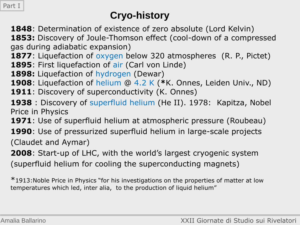
Cryo-history
1848: Determination of existence of zero absolute (Lord Kelvin) 1853: Discovery of Joule-Thomson effect (cool-down of a compressed gas during adiabatic expansion) 1877: Liquefaction of oxygen below 320 atmospheres (R. P., Pictet) 1895: First liquefaction of air (Carl von Linde) 1898: Liquefaction of hydrogen (Dewar) 1908: Liquefaction of helium @ 4.2 K (*K. Onnes, Leiden Univ., ND) 1911: Discovery of superconductivity (K. Onnes)
1938 : Discovery of superfluid helium (He II). 1978: Kapitza, Nobel Price in Physics 1971: Use of superfluid helium at atmospheric pressure (Roubeau)
1990: Use of pressurized superfluid helium in large-scale projects
(Claudet and Aymar)
2008: Start-up of LHC, with the world’s largest cryogenic system
(superfluid helium for cooling the superconducting magnets)
*1913:Noble Price in Physics “for his investigations on the properties of matter at low
temperatures which led, inter alia, to the production of liquid helium”
Amalia Ballarino XXII Giornate di Studio sui Rivelatori
Part I
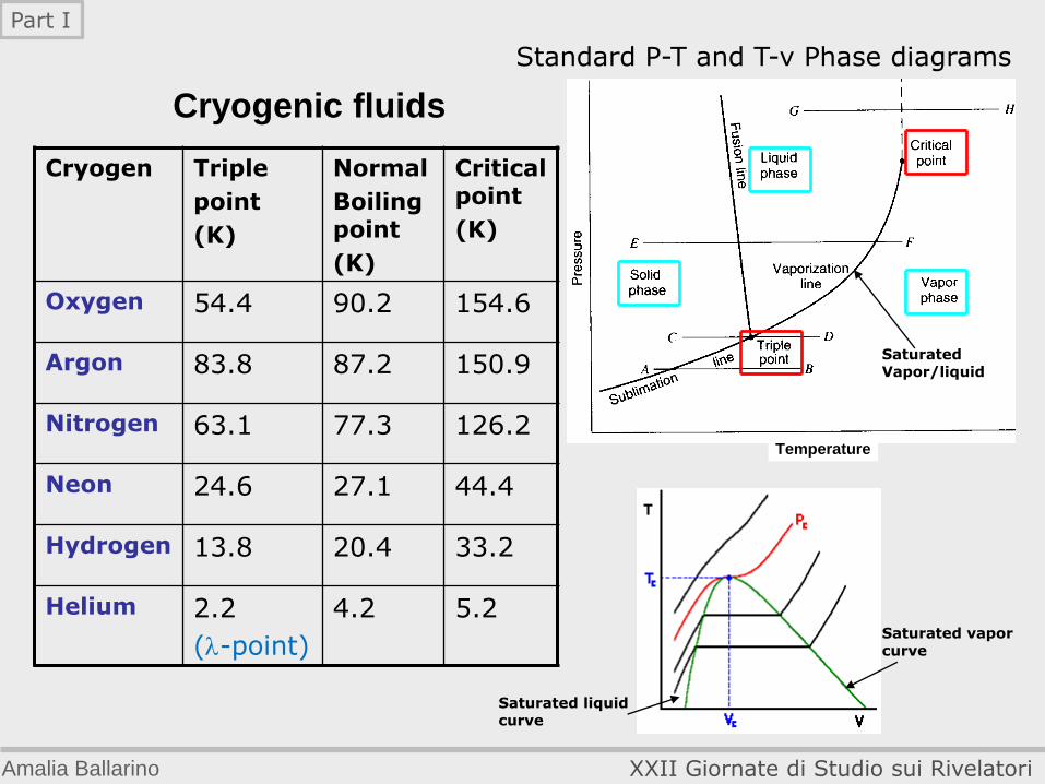
Cryogenic fluids
Cryogen Triple
point
(K)
Normal
Boiling point
(K)
Critical point
(K)
Oxygen 54.4 90.2 154.6
Argon 83.8 87.2 150.9
Nitrogen 63.1 77.3 126.2
Neon 24.6 27.1 44.4
Hydrogen 13.8 20.4 33.2
Helium 2.2
(-point)
4.2 5.2
Standard P-T and T-v Phase diagrams
Temperature
Saturated Vapor/liquid
Saturated liquid curve
Saturated vapor curve
Amalia Ballarino XXII Giornate di Studio sui Rivelatori
Part I
Helium
Second lightest elemental gas, after hydrogen Smallest of all molecules Colorless, odorless, inert and non-toxic Lowest boiling point of any element (-268.9°C, 4.2 K) Helium is produced continually by the radioactive decay of uranium and other elements, gradually working its way into the atmosphere Commercial extraction from air is impractical because helium's concentration is only about five parts per billion. Commercially, helium is obtained from the small fraction of natural gas deposits that contain helium volumes of 0.3 percent or higher Unusual characteristics: Helium remains liquid to absolute zero At 2.1 K, liquid helium exhibits super fluidity or virtually zero viscosity (Helium II), defies gravity to flow up container walls and becomes nearly a perfect heat conductor
Amalia Ballarino XXII Giornate di Studio sui Rivelatori
Part I
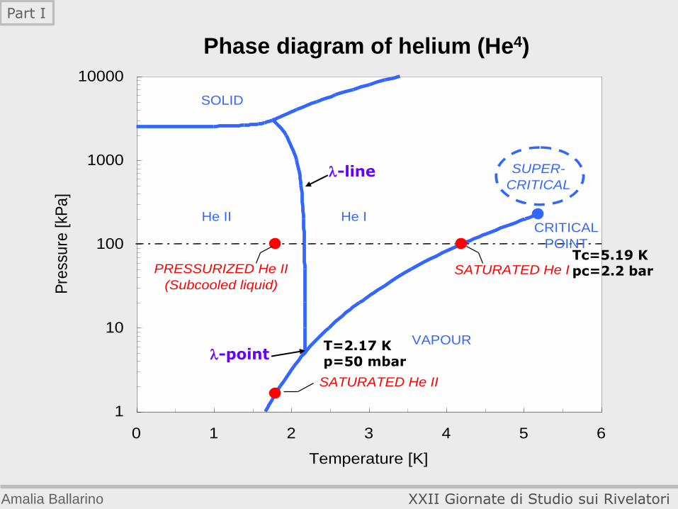
Phase diagram of helium (He4)
1
10
100
1000
10000
0 1 2 3 4 5 6
Temperature [K]
Pre
ssu
re [
kPa
]
SOLID
VAPOUR
He IHe IICRITICAL
POINT
PRESSURIZED He II
(Subcooled liquid)
SATURATED He II
SUPER-
CRITICAL
SATURATED He I
-line
-point
Tc=5.19 K pc=2.2 bar
T=2.17 K p=50 mbar
Amalia Ballarino XXII Giornate di Studio sui Rivelatori
Part I
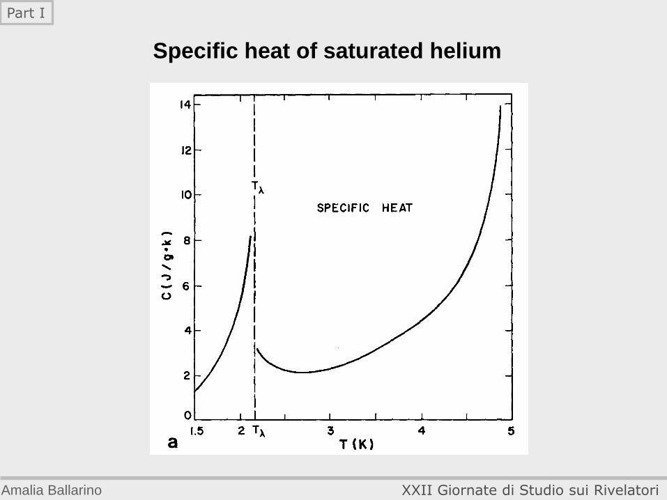
Specific heat of saturated helium
Amalia Ballarino XXII Giornate di Studio sui Rivelatori
Part I
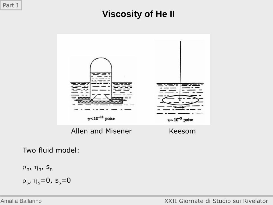
Viscosity of He II
Allen and Misener Keesom
Two fluid model: rn, n, sn
rs, s=0, ss=0
Amalia Ballarino XXII Giornate di Studio sui Rivelatori
Part I
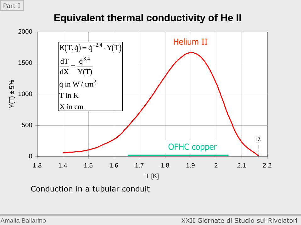
Equivalent thermal conductivity of He II
Conduction in a tubular conduit
0
500
1000
1500
2000
1.3 1.4 1.5 1.6 1.7 1.8 1.9 2 2.1 2.2
T [K]
Y(T
) ±
5%
T
K T,q q Y T
dT
dX
q
Y(T)
q in W / cm
T in K
X in cm
2.4
3.4
2
OFHC copper
Helium II
Amalia Ballarino XXII Giornate di Studio sui Rivelatori
Part I
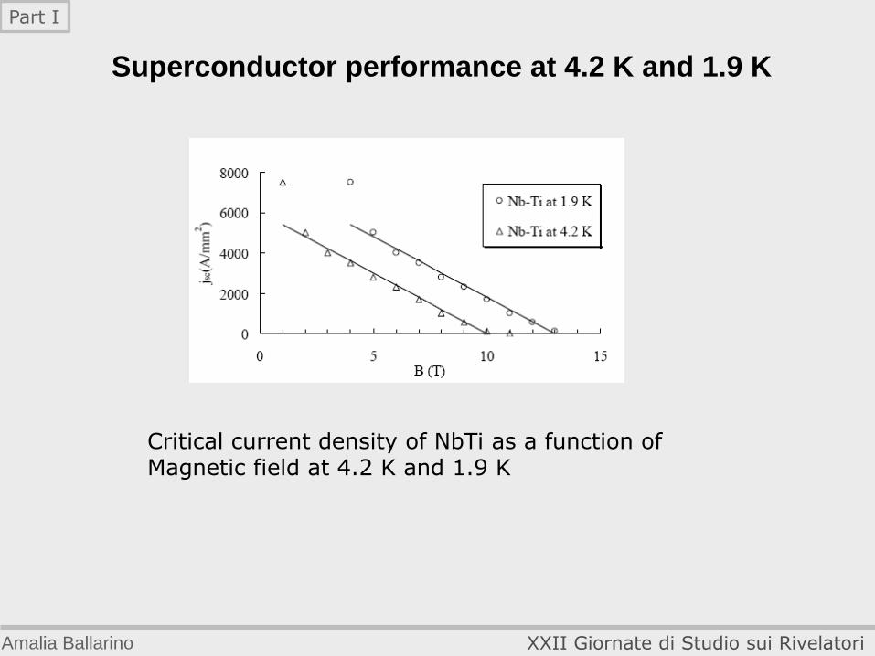
Superconductor performance at 4.2 K and 1.9 K
Critical current density of NbTi as a function of Magnetic field at 4.2 K and 1.9 K
Amalia Ballarino XXII Giornate di Studio sui Rivelatori
Part I
1
10
100
1000
10000
0 1 2 3 4 5 6
Temperature [K]
Pre
ssu
re [
kPa
]
SOLID
VAPOUR
He IHe IICRITICAL
POINT
PRESSURIZED He II
(Subcooled liquid)
SATURATED He II
SUPER-
CRITICAL
SATURATED He I
-line
-point
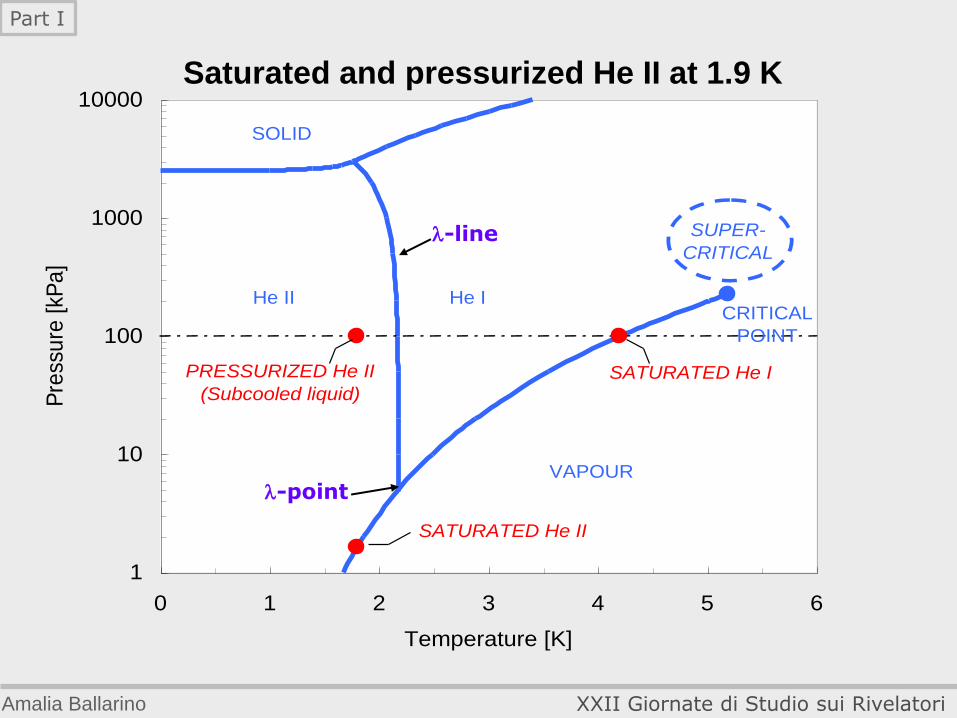
Saturated and pressurized He II at 1.9 K
Amalia Ballarino XXII Giornate di Studio sui Rivelatori
Part I
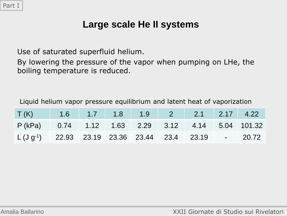
Use of saturated superfluid helium.
By lowering the pressure of the vapor when pumping on LHe, the boiling temperature is reduced.
T (K) 1.6 1.7 1.8 1.9 2 2.1 2.17 4.22
P (kPa) 0.74 1.12 1.63 2.29 3.12 4.14 5.04 101.32
L (J g-1) 22.93 23.19 23.36 23.44 23.4 23.19 - 20.72
Liquid helium vapor pressure equilibrium and latent heat of vaporization
Large scale He II systems
Amalia Ballarino XXII Giornate di Studio sui Rivelatori
Part I
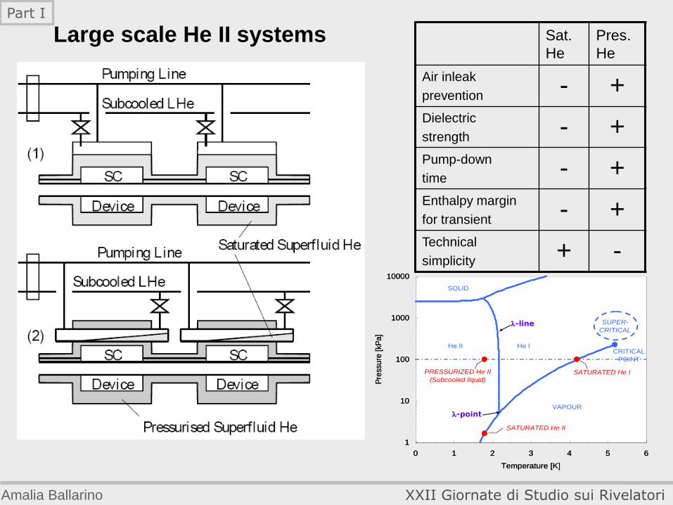
Large scale He II systems Sat.
He
Pres.
He
Air inleak
prevention - + Dielectric
strength - + Pump-down
time - + Enthalpy margin
for transient - + Technical
simplicity + -
1
10
100
1000
10000
0 1 2 3 4 5 6
Temperature [K]
Pre
ssu
re [
kPa
]
SOLID
VAPOUR
He IHe IICRITICAL
POINT
PRESSURIZED He II
(Subcooled liquid)
SATURATED He II
SUPER-
CRITICAL
SATURATED He I
-line
-point
1
10
100
1000
10000
0 1 2 3 4 5 6
Temperature [K]
Pre
ssu
re [
kPa
]
SOLID
VAPOUR
He IHe IICRITICAL
POINT
PRESSURIZED He II
(Subcooled liquid)
SATURATED He II
SUPER-
CRITICAL
SATURATED He I
-line
-point
Amalia Ballarino XXII Giornate di Studio sui Rivelatori
Part I
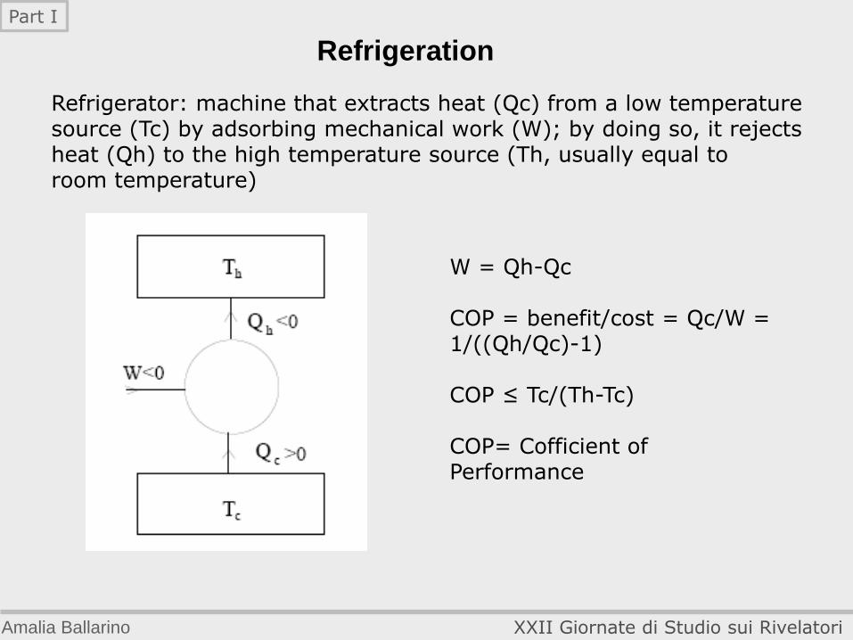
Refrigeration
Refrigerator: machine that extracts heat (Qc) from a low temperature source (Tc) by adsorbing mechanical work (W); by doing so, it rejects heat (Qh) to the high temperature source (Th, usually equal to room temperature)
W = Qh-Qc COP = benefit/cost = Qc/W = 1/((Qh/Qc)-1) COP ≤ Tc/(Th-Tc) COP= Cofficient of Performance
Amalia Ballarino XXII Giornate di Studio sui Rivelatori
Part I
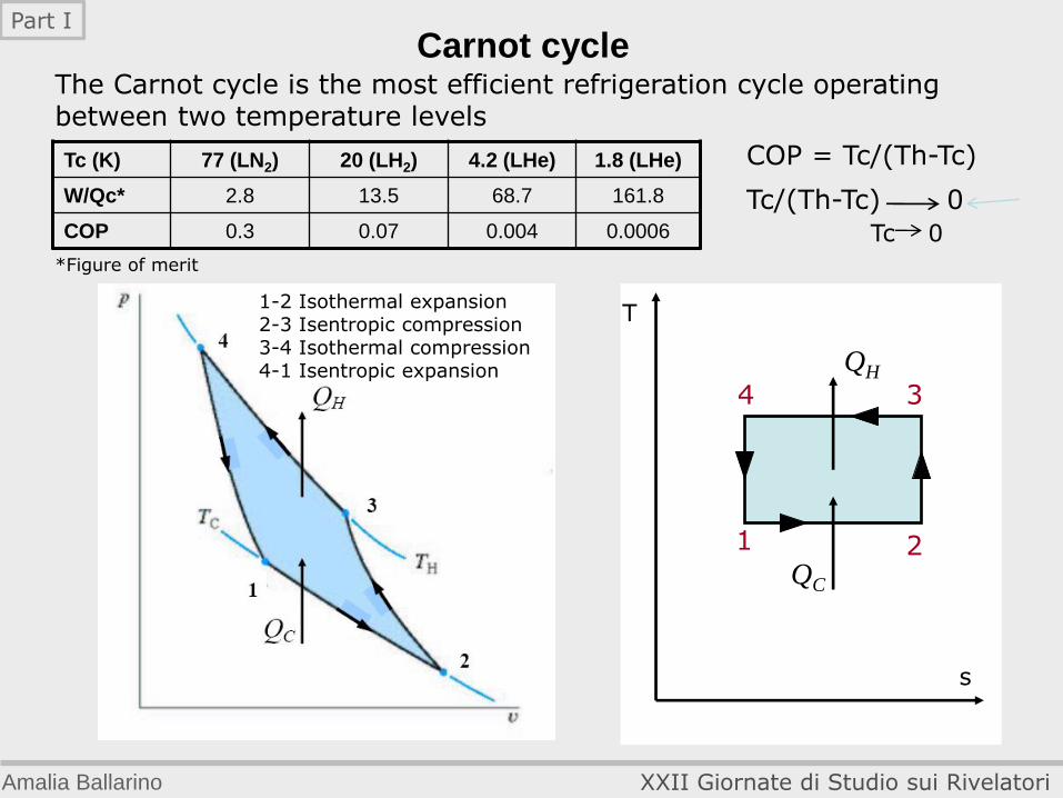
The Carnot cycle is the most efficient refrigeration cycle operating between two temperature levels
Carnot cycle
1 2
3 4
T
s
QC
QH
COP = Tc/(Th-Tc) Tc/(Th-Tc) 0
Tc 0
1-2 Isothermal expansion 2-3 Isentropic compression 3-4 Isothermal compression 4-1 Isentropic expansion
Tc (K) 77 (LN2) 20 (LH2) 4.2 (LHe) 1.8 (LHe)
W/Qc* 2.8 13.5 68.7 161.8
COP 0.3 0.07 0.004 0.0006
*Figure of merit
Amalia Ballarino XXII Giornate di Studio sui Rivelatori
Part I
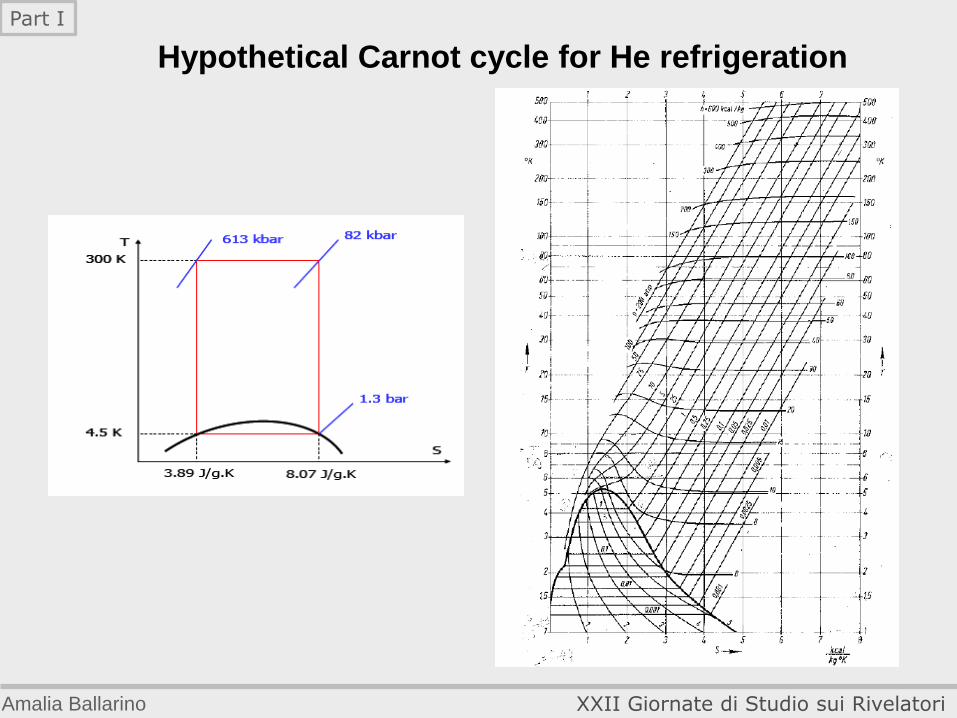
Hypothetical Carnot cycle for He refrigeration
Amalia Ballarino XXII Giornate di Studio sui Rivelatori
Part I
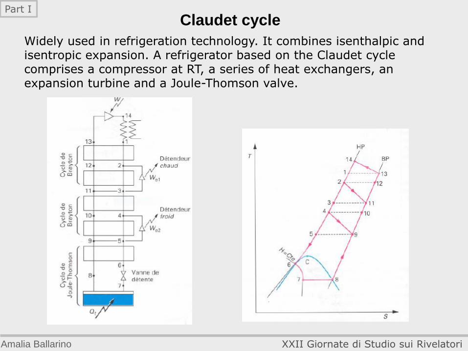
Claudet cycle
Widely used in refrigeration technology. It combines isenthalpic and isentropic expansion. A refrigerator based on the Claudet cycle comprises a compressor at RT, a series of heat exchangers, an expansion turbine and a Joule-Thomson valve.
Amalia Ballarino XXII Giornate di Studio sui Rivelatori
Part I
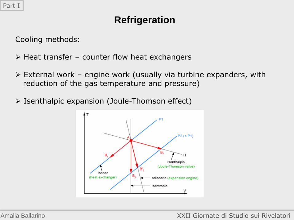
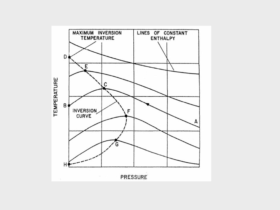
Refrigeration Cooling methods: Heat transfer – counter flow heat exchangers External work – engine work (usually via turbine expanders, with reduction of the gas temperature and pressure) Isenthalpic expansion (Joule-Thomson effect)
Amalia Ballarino XXII Giornate di Studio sui Rivelatori
Part I
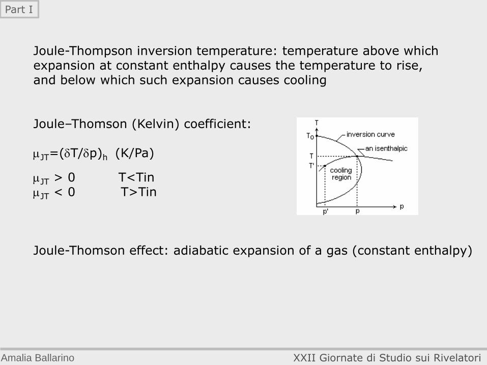
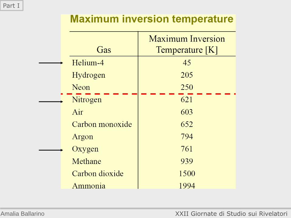
Joule-Thompson inversion temperature: temperature above which expansion at constant enthalpy causes the temperature to rise, and below which such expansion causes cooling Joule–Thomson (Kelvin) coefficient: JT=(T/p)h (K/Pa)
JT > 0 T<Tin JT < 0 T>Tin Joule-Thomson effect: adiabatic expansion of a gas (constant enthalpy)
Amalia Ballarino XXII Giornate di Studio sui Rivelatori
Part I
Amalia Ballarino XXII Giornate di Studio sui Rivelatori
Part I
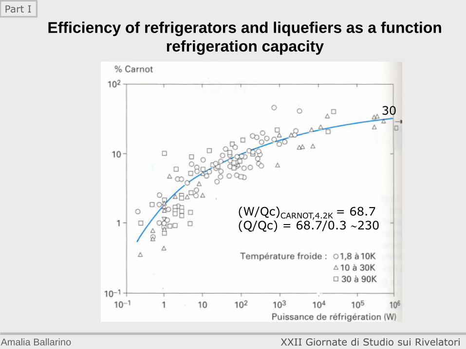
Efficiency of refrigerators and liquefiers as a function
refrigeration capacity
Amalia Ballarino XXII Giornate di Studio sui Rivelatori
Part I
(W/Qc)CARNOT,4.2K = 68.7 (Q/Qc) = 68.7/0.3 230
30

0.999999991c0.999999991c
The cryogenic system for the LHC machine
Amalia Ballarino XXII Giornate di Studio sui Rivelatori
Part I
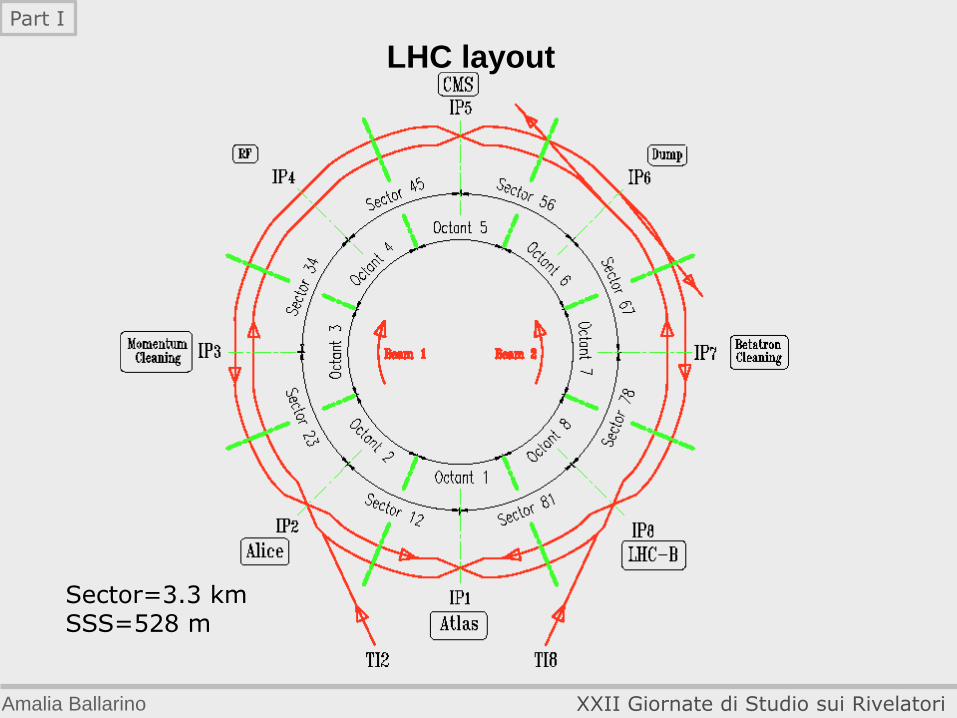
LHC layout
Sector=3.3 km SSS=528 m
Amalia Ballarino XXII Giornate di Studio sui Rivelatori
Part I

From the LEP to the LHC machine
8000
Amalia Ballarino XXII Giornate di Studio sui Rivelatori
Part I
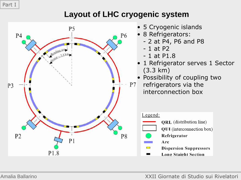
Layout of LHC cryogenic system
• 5 Cryogenic islands • 8 Refrigerators: - 2 at P4, P6 and P8 - 1 at P2 - 1 at P1.8 • 1 Refrigerator serves 1 Sector (3.3 km) • Possibility of coupling two refrigerators via the
interconnection box
Amalia Ballarino XXII Giornate di Studio sui Rivelatori
Part I
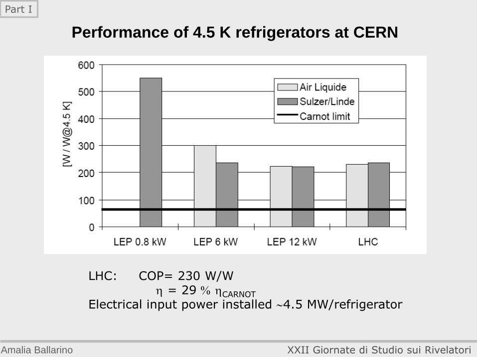
Performance of 4.5 K refrigerators at CERN
Amalia Ballarino XXII Giornate di Studio sui Rivelatori
Part I
LHC: COP= 230 W/W = 29 CARNOT
Electrical input power installed 4.5 MW/refrigerator
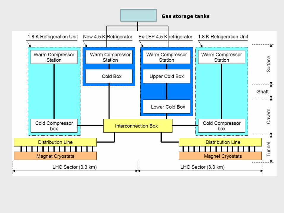
Gas storage tanks
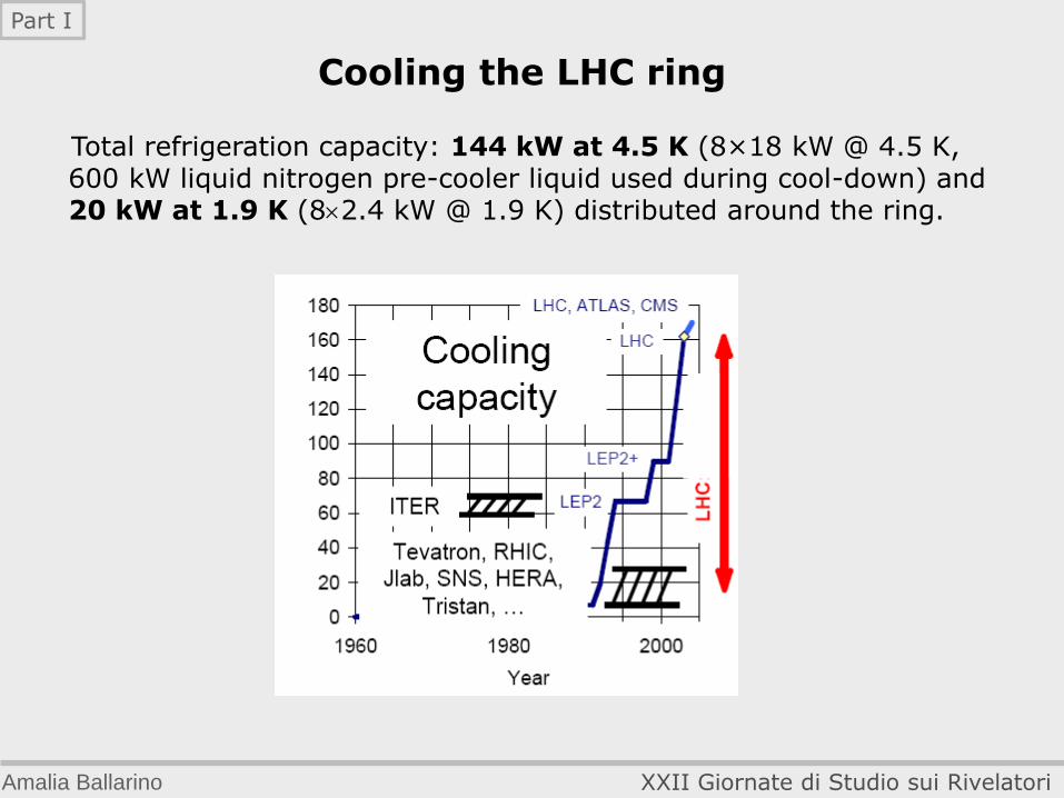
Cooling the LHC ring
Total refrigeration capacity: 144 kW at 4.5 K (8×18 kW @ 4.5 K, 600 kW liquid nitrogen pre-cooler liquid used during cool-down) and 20 kW at 1.9 K (82.4 kW @ 1.9 K) distributed around the ring.
Amalia Ballarino XXII Giornate di Studio sui Rivelatori
Part I
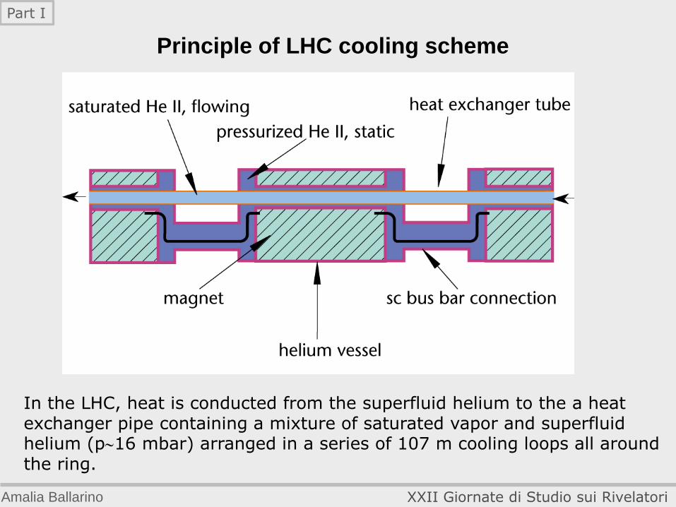
In the LHC, heat is conducted from the superfluid helium to the a heat exchanger pipe containing a mixture of saturated vapor and superfluid helium (p16 mbar) arranged in a series of 107 m cooling loops all around the ring.
Principle of LHC cooling scheme
Amalia Ballarino XXII Giornate di Studio sui Rivelatori
Part I
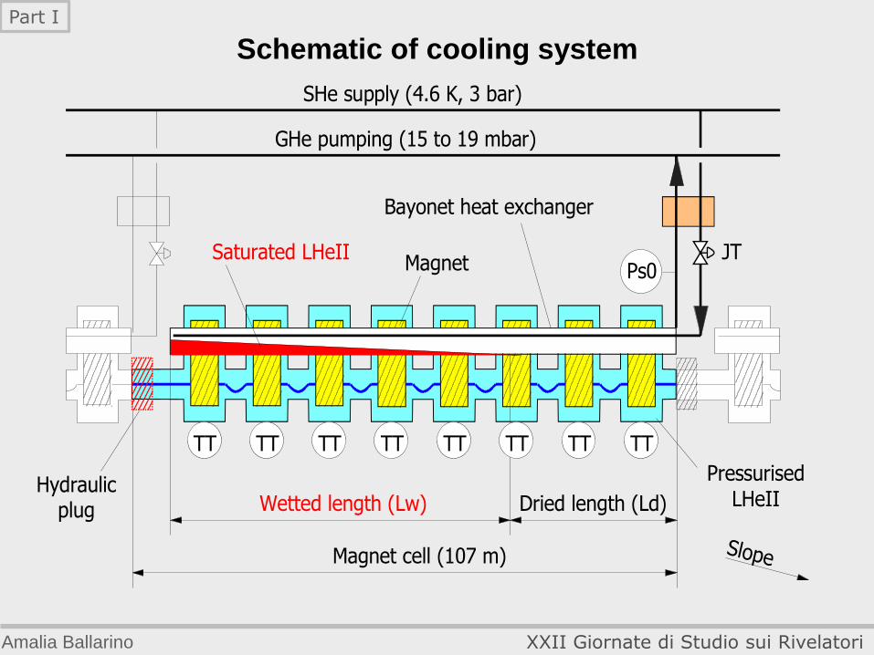
Schematic of cooling system
Slope
MagnetSaturated LHeII
Magnet cell (107 m)
Bayonet heat exchanger
GHe pumping (15 to 19 mbar)
SHe supply (4.6 K, 3 bar)
Ps0
Wetted length (Lw) Dried length (Ld)
JT
Hydraulicplug
PressurisedLHeII
TT TT TT TT TT TT TT TT
Amalia Ballarino XXII Giornate di Studio sui Rivelatori
Part I
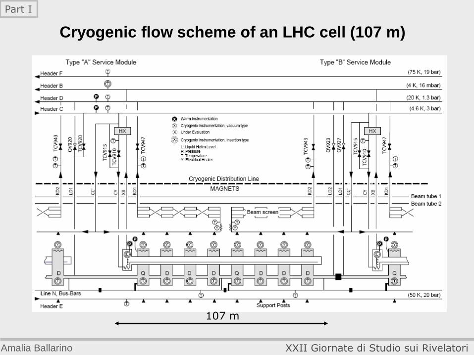
Cryogenic flow scheme of an LHC cell (107 m)
107 m
Amalia Ballarino XXII Giornate di Studio sui Rivelatori
Part I
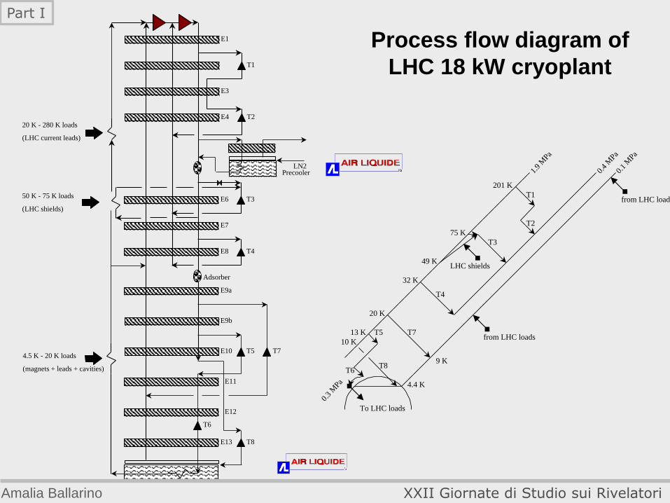
Temperature levels in the LHC cryogenic system
In view of the high cost of refrigeration at 1.8 K, the main heat influx in intercepted at higher temperatures. The temperature levels are: 50 K to 75 K for thermal shielding of the cold masses; 4.6 K to 20 K for cooling of the beam screens and lower temperature interception; 1.9 K quasi-isothermal superfluid helium for the magnets; 4 K helium at very low pressure for transporting the superheated helium flow coming from the 1.8 K heat exchanger tubes across the sector length to the 1.8 K refrigeration unit; 4.5 K saturated helium for some insertion magnets, RF cavities, and the bottom end of the HTS leads; 20 K to 300 K cooling for the resistive upper section of the HTS leads.
Amalia Ballarino XXII Giornate di Studio sui Rivelatori
Part I
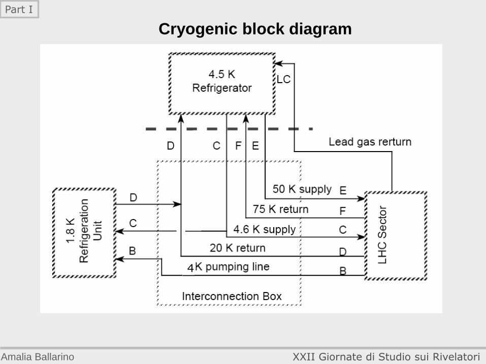
Cryogenic block diagram
4
Amalia Ballarino XXII Giornate di Studio sui Rivelatori
Part I
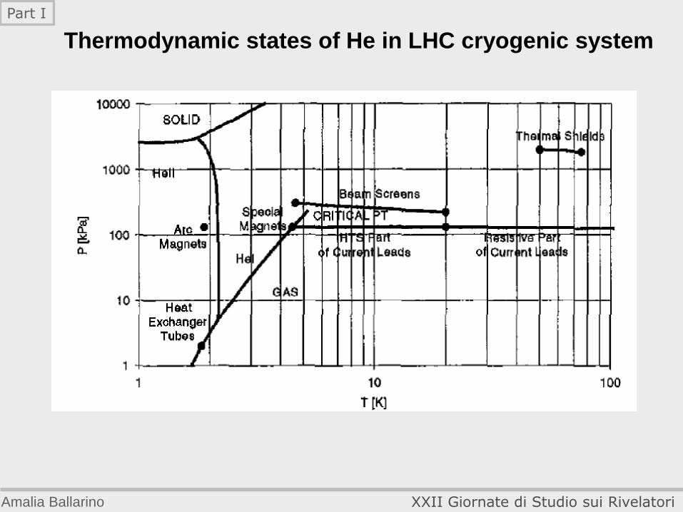
Thermodynamic states of He in LHC cryogenic system
Amalia Ballarino XXII Giornate di Studio sui Rivelatori
Part I
T54.5 K - 20 K loads
(magnets + leads + cavities)
T7
T1
T2
T3
T4
T8
T6
E1
E7
E3
E4
E6
E8
E9a
E9b
E10
E11
E12
E13
LN2Precooler
20 K - 280 K loads
(LHC current leads)
50 K - 75 K loads
(LHC shields)
Adsorber
T1
T3
T7
T4
T8
T5
T6
201 K
75 K
49 K
32 K
20 K
13 K
10 K
9 K
4.4 K
0.1
MPa
0.4
MPa
1.9
MPa
0.3
MPa
T2
LHC shields
To LHC loads
from LHC loads
from LHC loads
Process flow diagram of
LHC 18 kW cryoplant
Amalia Ballarino XXII Giornate di Studio sui Rivelatori
Part I

1.8 K He refrigeration system
0.3 MPa4.6 K
0.13 MPa,20 -30 K
WC
S
1.8
K R
efr
igera
tio
n U
nit
LHe 1.8 K Q1.8K
CC
B
4.5 KRefrigerator
B
D
C
Cold
com
pre
ssors
Tu
rbln
e
Adsor-bers
LHC SectorLoad
Installed pumping capacity 125 g/s at 15 mbar (i.e. ~2.4 kW @ 1.8 K)
Amalia Ballarino XXII Giornate di Studio sui Rivelatori
Part I
LHC Distribution system
The refrigerating helium of the magnets and cavities have to be distributed over the 27 km of the accelerator, in the LHC tunnel, 100 m below ground level.
Due to the size of the experiment, ultra high performance cryogenic lines have been specially designed for the LHC project.
The achieved performance of the line is: about 0.05 W/m on each of the 4.5 K tubes of the transfer line, a performance around 10 times better than usually achieved
Amalia Ballarino XXII Giornate di Studio sui Rivelatori
Part I
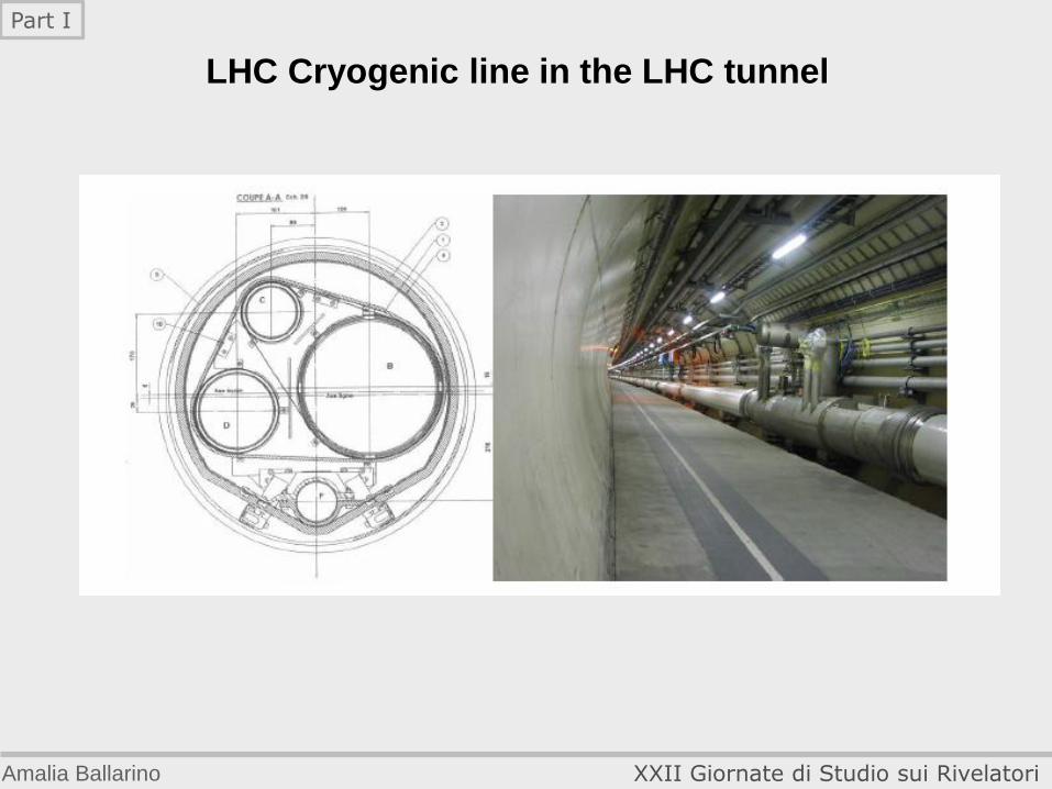
LHC Cryogenic line in the LHC tunnel
Amalia Ballarino XXII Giornate di Studio sui Rivelatori
Part I
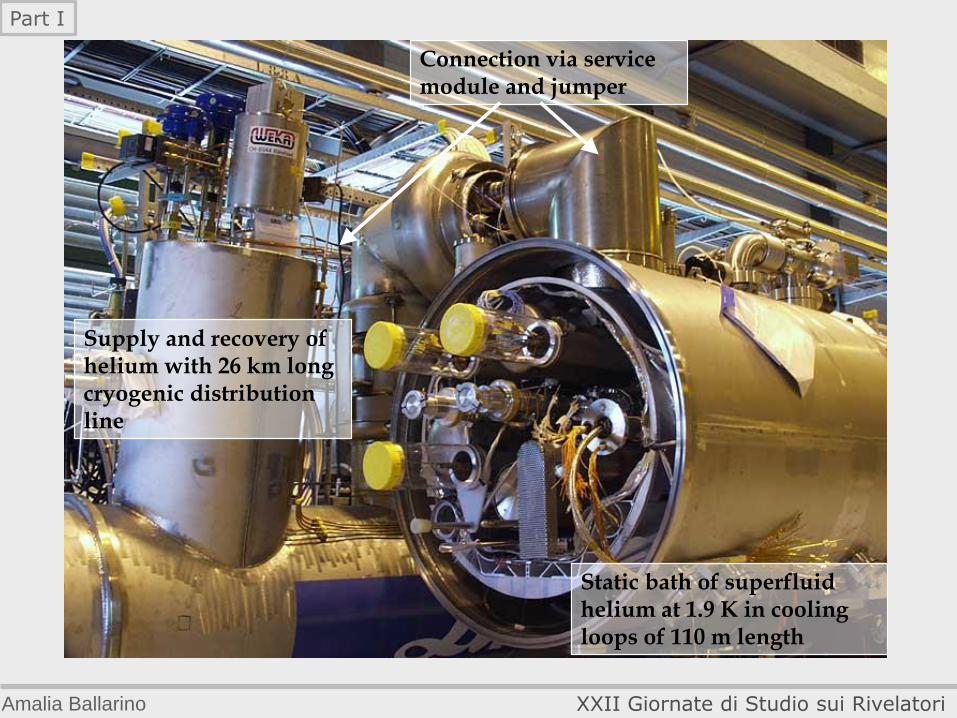
Supply and recovery of helium with 26 km long cryogenic distribution line
Static bath of superfluid helium at 1.9 K in cooling loops of 110 m length
Connection via service module and jumper
Amalia Ballarino XXII Giornate di Studio sui Rivelatori
Part I

Transverse cross section of the LHC tunnel
Amalia Ballarino XXII Giornate di Studio sui Rivelatori
Part I

Cool-down of LHC machine
Removal of air in circuit by evacuation and He filling (1 week);
Removal of dust and debris by flushing the helium circuits with
high helium flow at 300 K (1 to 2 week per sector) ;
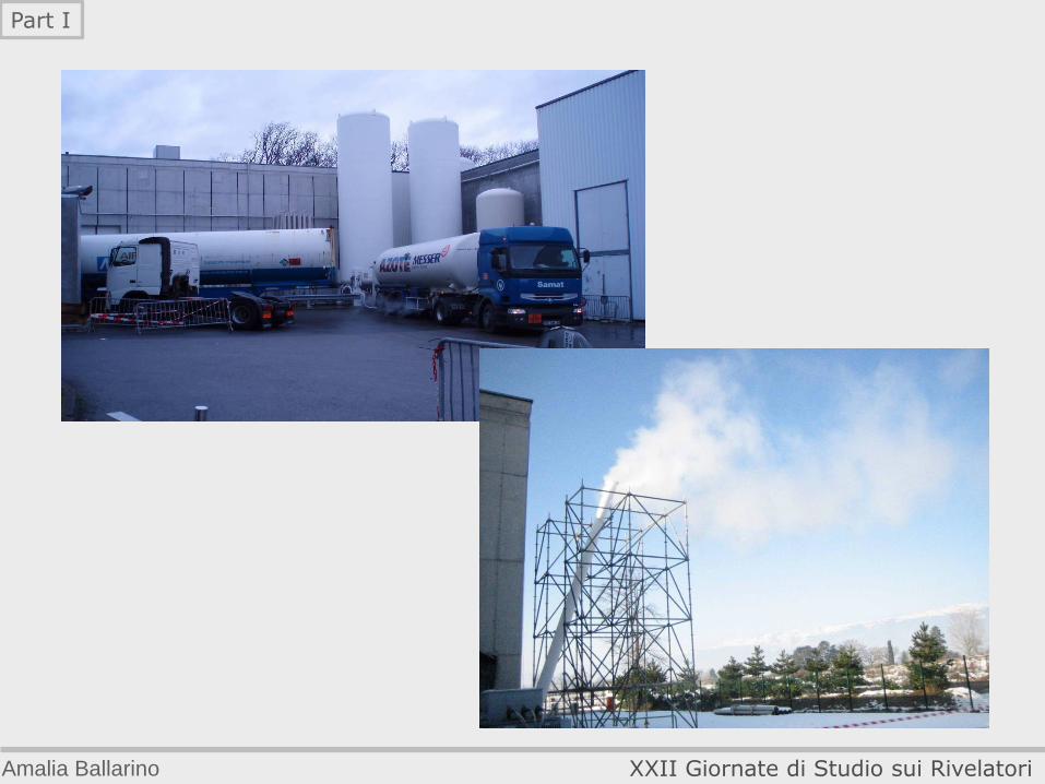
Cool-down of 4625 t per sector over 3.3 km: From 300 to 80 K: 600 kW pre-cooling with LN2, up to ~5 t/h, 6 LN2 trailer per day during 10 days (1250 t of LN2 in total); From 80 to 5 K: Cryoplant turbo-expander cooling;
LHe filling: 15 t of LHe in total (4 trailers); LHe filling and cool-down completion by using the 1.8 K refrigeration unit (1 week/sector)
Amalia Ballarino XXII Giornate di Studio sui Rivelatori
Part I
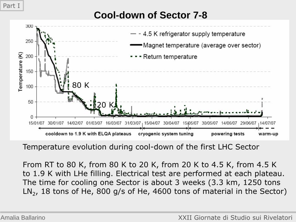
Cool-down of Sector 7-8
Temperature evolution during cool-down of the first LHC Sector From RT to 80 K, from 80 K to 20 K, from 20 K to 4.5 K, from 4.5 K to 1.9 K with LHe filling. Electrical test are performed at each plateau. The time for cooling one Sector is about 3 weeks (3.3 km, 1250 tons LN2, 18 tons of He, 800 g/s of He, 4600 tons of material in the Sector)
80 K
20 K
Amalia Ballarino XXII Giornate di Studio sui Rivelatori
Part I
Amalia Ballarino XXII Giornate di Studio sui Rivelatori
Part I
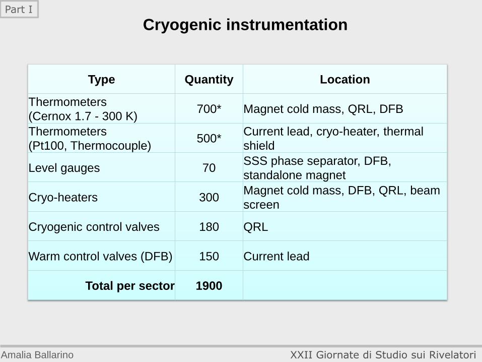
Type Quantity Location
Thermometers
(Cernox 1.7 - 300 K) 700* Magnet cold mass, QRL, DFB
Thermometers
(Pt100, Thermocouple) 500*
Current lead, cryo-heater, thermal
shield
Level gauges 70 SSS phase separator, DFB,
standalone magnet
Cryo-heaters 300 Magnet cold mass, DFB, QRL, beam
screen
Cryogenic control valves 180 QRL
Warm control valves (DFB) 150 Current lead
Total per sector 1900
Cryogenic instrumentation
Amalia Ballarino XXII Giornate di Studio sui Rivelatori
Part I

Heat load and cryostat design
Heat inleaks
– Radiation 70 K shield, MLI
– Residual gas conduction Vacuum < 10-4 Pa
– Solid conduction Non-metallic supports Heat intercepts
Joule heating
– Superconductor splices Resistance < a few nW
Beam-induced heating
– Synchrotron radiation (0.6 W/m) }
– Beam image currents (0.8 W/m) } 5-20 K beam screens
– Localized heat due to loss of particles }
(e.g particles escaping collimations)
Amalia Ballarino XXII Giornate di Studio sui Rivelatori
Part I
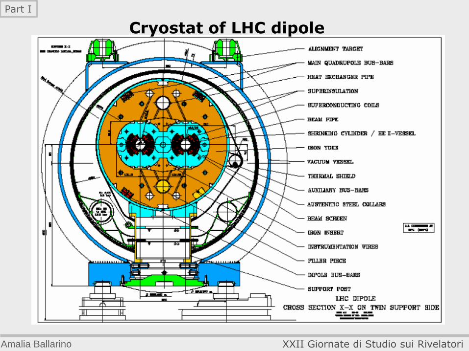
Cryostat of LHC dipole
Amalia Ballarino XXII Giornate di Studio sui Rivelatori
Part I
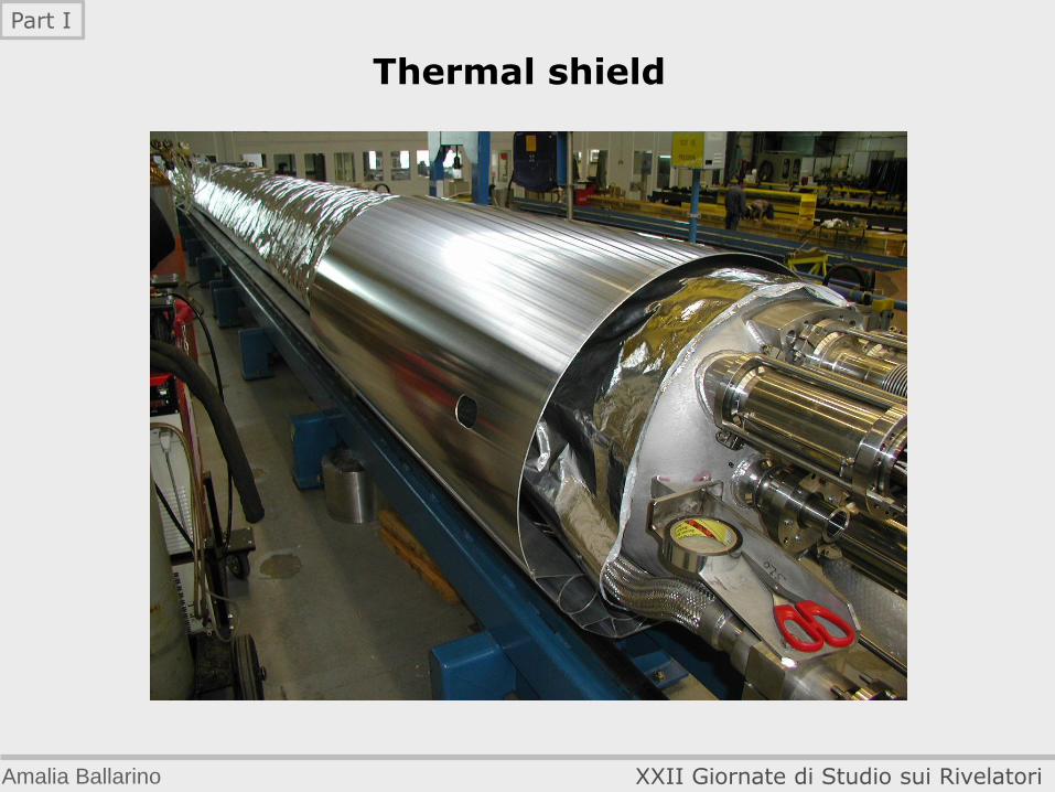
Thermal shield
Amalia Ballarino XXII Giornate di Studio sui Rivelatori
Part I
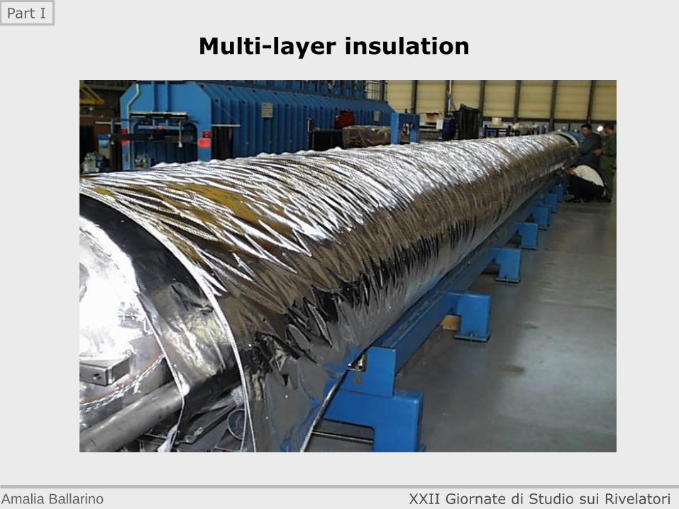
Multi-layer insulation
Amalia Ballarino XXII Giornate di Studio sui Rivelatori
Part I
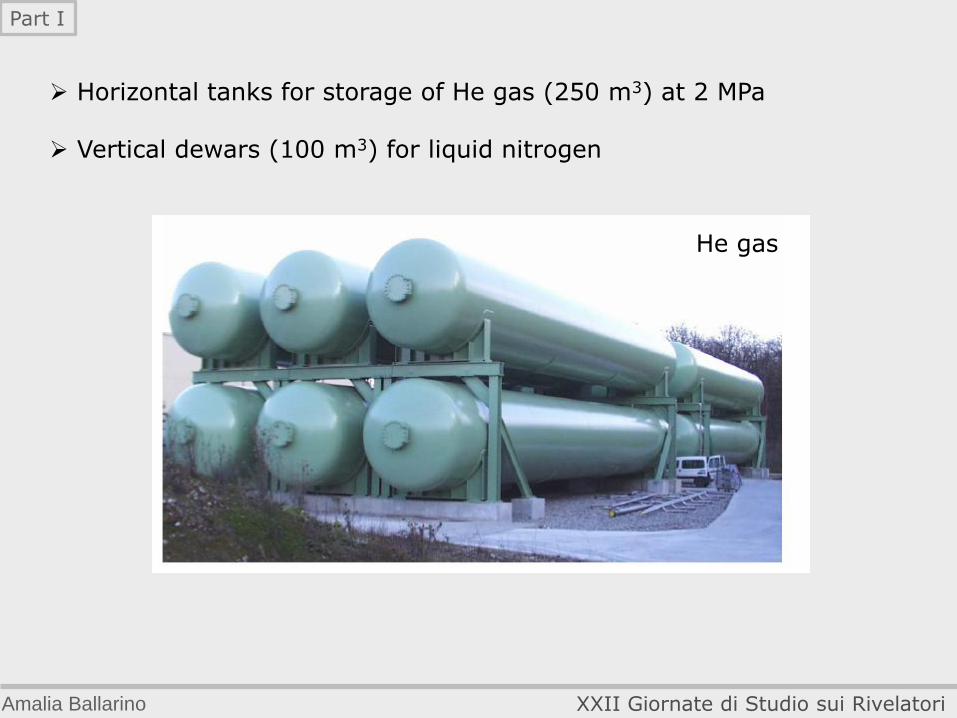
Horizontal tanks for storage of He gas (250 m3) at 2 MPa Vertical dewars (100 m3) for liquid nitrogen
He gas
Amalia Ballarino XXII Giornate di Studio sui Rivelatori
Part I
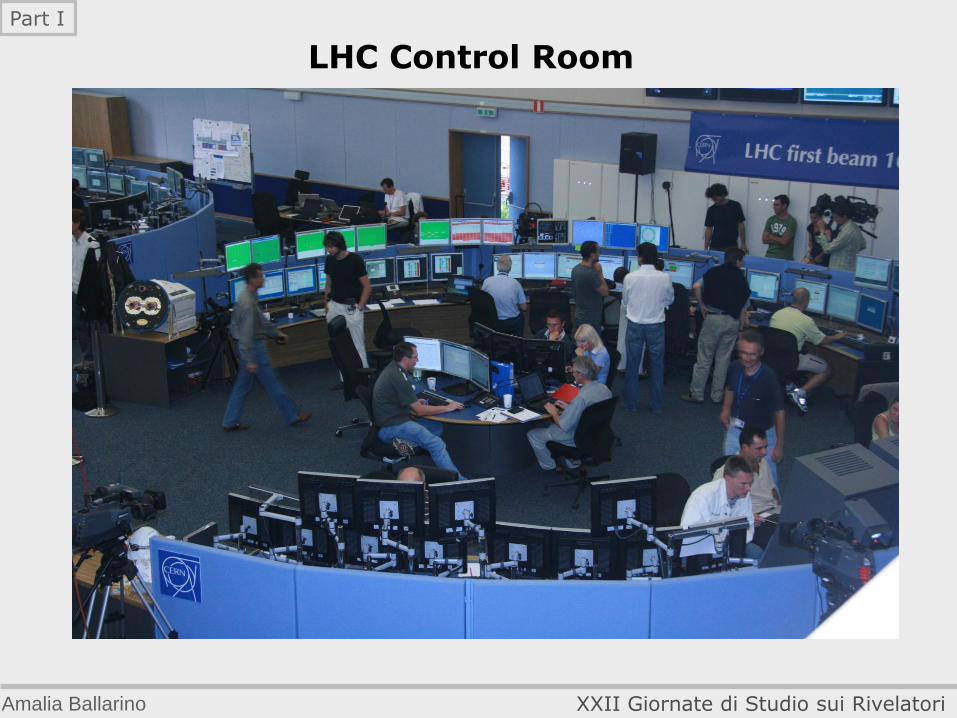
LHC Control Room
Amalia Ballarino XXII Giornate di Studio sui Rivelatori
Part I
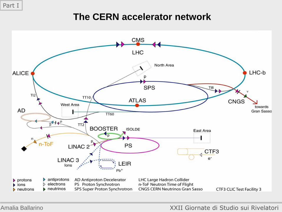
The CERN accelerator network
Amalia Ballarino XXII Giornate di Studio sui Rivelatori
Part I


