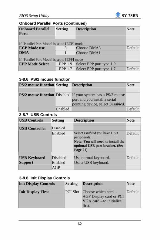
SY-7SBB Motherboard **************************************************** Socket 370 Celeron Processor supported SIS600 Motherboard 66/100 MHz Front Side Bus supported Baby AT Form Factor **************************************************** User's Manual
Trademarks:Soyo is the registered trademark of Soyo Computer Inc. All trademarks are theproperties of their owners.
Product Rights:All names of the product and corporate mentioned in this publication are used foridentification purposes only. The registered trademarks and copyrights belong totheir respective companies.
Copyright Notice:All rights reserved. This manual has been copyrighted by Soyo Computer Inc. Nopart of this manual may be reproduced, transmitted, transcribed, translated into anyother language, or stored in a retrieval system, in any form or by any means, suchas by electronic, mechanical, magnetic, optical, chemical, manual or otherwise,without permission in writing from Soyo Computer Inc.
Disclaimer:Soyo Computer Inc. makes no representations or warranties regarding the contentsof this manual. We reserve the right to amend the manual or revise thespecifications of the product described in it from time to time without obligation tonotify any person of such revision or amend. The information contained in thismanual is provided to our customers for general use. Customers should be awarethat the personal computer field is subject to many patents. All of our customersshould ensure that their use of our products does not infringe upon any patents. It isthe policy of Soyo Computer Inc. to respect the valid patent rights of third partiesand not to infringe upon or to cause others to infringe upon such rights.
Restricted Rights Legend:Use, duplication, or disclosure by the Government is subject to restrictions setforth in subparagraph (c)(1)(ii) of the Rights in Technical Data and ComputerSoftware clause at 252.277-7013.
About This Guide:This Quick Start Guide can help system manufacturers and end users in setting upand installing the Motherboard. Information in this guide has been carefullychecked for reliability; however, to the correctness of the contents there is noguarantee given. The information in this document is subject to amend withoutnotice.
For further information, please visit our Web Site on the Internet. The address is"http://www.soyo.com.tw".
U CMOS Clear JumperV Chassis Cooling FanW Front panel connectors
X PCI Audio Card HeaderY Flash ROMZ SiS 5595 Chip
Hardware Installation SY-7SBB
6
Chapter 2
HARDWARE INSTALLATION
Congratulations on your purchase of the SY-7SBB Motherboard. This
chapter will help you install and connect your new Motherboard.
Note: Do not unpack the Motherboard from its protective anti-
static packaging until you have made the following preparations.
2-1 PREPARATIONSGather and prepare all the following hardware equipment to complete the
installation successfully:
1. Celeron processor with CPU cooling fan.
2. DIMM memory module
3. Computer case and chassis with adequate power supply unit
4. Monitor
5. Keyboard
6. Pointing Device (mouse)
7. Speaker(s) (optional)
8. Disk Drives: HDD, CD-ROM, Floppy drive …
9. External Peripherals: Printer, Plotter, and Modem (optional)
10. Internal Peripherals: Modem and LAN cards (optional)
Hardware Installation SY-7SBB
7
2-2 UNPACKING THE MOTHERBOARDWhen unpacking the Motherboard, check for the following items:
u The SY-7SBB SiS 600 AGP/PCI Motherboard
u The User’s Manual
u The Installation CD-ROM
u One IDE Device Flat Cable
u One Floppy Disk Drive Flat Cable
u One 9-pin serial prot connector with 9-pin flat cableand 6-pin PS/2 mouse connector with 6-pin cable
u One 25-pin parallel port connector with 25-pin flatcable and 9-pin serial port connector with 9-pin flatcable
Warning: Do not unpack the Motherboard from its anti-static packaging
until you are ready to install it.
Like most electronic equipment, your Motherboard may be damaged by
electrostatic discharge. To avoid permanent damage to components ground
yourself while working by using a grounding strap. Otherwise, ground
yourself frequently by touching the unpainted portion of the computer
chassis to drain the static charges.
Handle the Motherboard carefully, holding it by the edges. You are now
ready to start the installation.
Hardware Installation SY-7SBB
8
2-3 INSTALLATION GUIDEWe will now begin the installation of the Motherboard. Please follow the
step-by-step procedure designed to lead you to a complete and correct
installation.
Warning: Turn off the power to the Motherboard, system
chassis, and peripheral devices before performing any work on
the Motherboard or system.
BEGIN THE INSTALLATION
Hardware Installation SY-7SBB
9
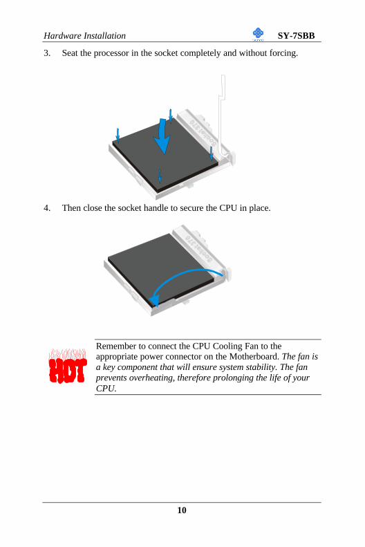
2-3.1 CPU InstallationFollow the steps below in order to perform the installation of your newSY-7SBB Motherboard.
Mark your CPU Frequency: Record the working frequency ofyour CPU that should be clearly marked on the CPU cover.
300MHz (66 x 4.5) 333MHz (66 x 5.0) 366MHz (66 x 5.5) 400MHz (66 x 6.0)433MHz (66 x 6.5) 466MHz (66 x7..0) 500MHz (66 x7.5)
This Motherboard is designed to be able to support processors with 100MHzFSB. However, Socket 370 processors with 100MHz FSB are not available yetat this moment for testing.
CPU Mount Procedure: To mount the Celeron TM processor that youhave purchased separately, follow these instructions.
1. Lift the socket handle up to a vertical position.
2. Align the blunt edge of the CPU with the matching pinhole on the
socket.
Hardware Installation SY-7SBB
10
3. Seat the processor in the socket completely and without forcing.
4. Then close the socket handle to secure the CPU in place.
Remember to connect the CPU Cooling Fan to theappropriate power connector on the Motherboard. The fan isa key component that will ensure system stability. The fanprevents overheating, therefore prolonging the life of yourCPU.
Hardware Installation SY-7SBB
11
2-3.2 SDRAM Memory Module Installation
This Motherboard features 3 x DIMM Banks for 168-pin 3.3V unbuffered
DIMM modules. Your board comes with three DIMM sockets, providing
support for up to 768MB of main memory using DIMM modules from
8MB to 256MB. For 66MHz front side bus CPUs use 12ns or faster
memory; for 100MHz front side bus CPUs use 8ns (100MHz, PC100
Note : 1. There are two types of DIMM module with different
operating voltages: 3.3V and 5.0V. Please note that only 3.3V EDO DIMM modules can be used on this Motherboard.
2. This motherboard does not support registered SDRAM DIMM Modules.
Hardware Installation SY-7SBB
13
2-3.3 Motherboard Connector
2-3.3.1 IDE Device Installation (HDD, CD-ROM)
This Motherboard offers a primary and secondary IDE device connector
(IDE1, IDE2). It can support up to four high-speed HDD or CD-ROM.
Connect one side of the 40-pin flat cable to the IDE device (HDD or CD-
ROM) and plug the other end to the primary (IDE1) or secondary (IDE2)
IDE connector on the Motherboard.
1
*
22
1
1
39
39
IDE 2
IDE 1
Pin -1
SecondaryIDE
PrimaryIDE
Hardware Installation SY-7SBB
14
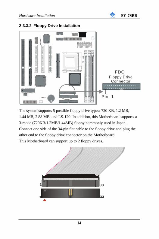
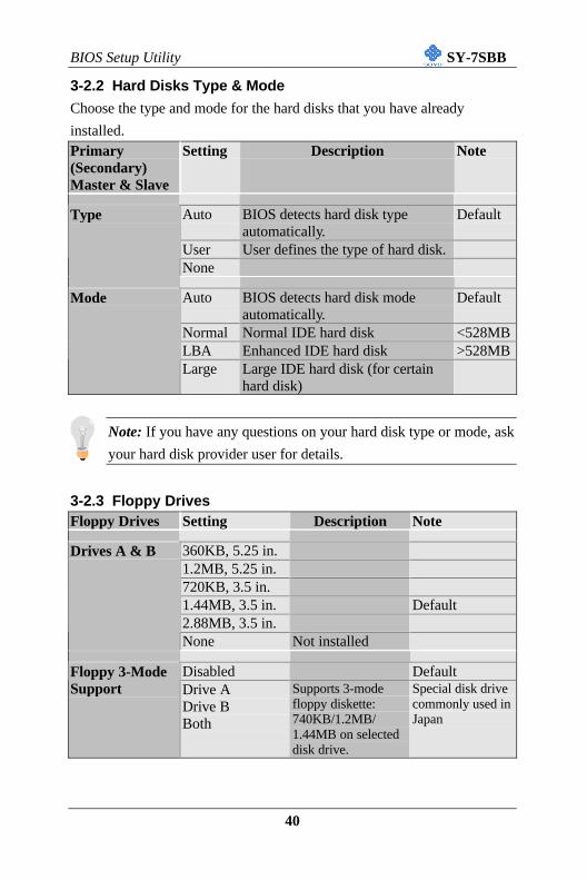
2-3.3.2 Floppy Drive Installation
The system supports 5 possible floppy drive types: 720 KB, 1.2 MB,
1.44 MB, 2.88 MB, and LS-120. In addition, this Motherboard supports a
3-mode (720KB/1.2MB/1.44MB) floppy commonly used in Japan.
Connect one side of the 34-pin flat cable to the floppy drive and plug the
other end to the floppy drive connector on the Motherboard.
This Motherboard can support up to 2 floppy drives.
1
*
22
1
1
33
33
FDC
Pin -1
Floppy DriveConnector
Hardware Installation SY-7SBB
15
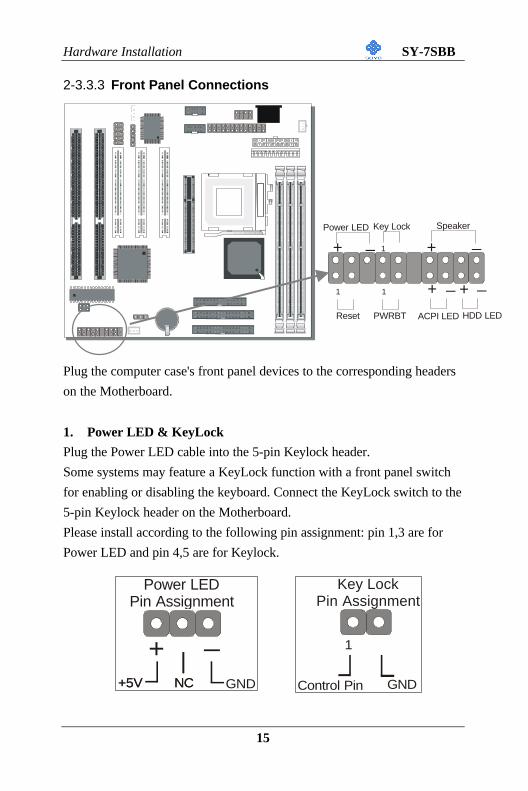
2-3.3.3 Front Panel Connections
Plug the computer case's front panel devices to the corresponding headers
on the Motherboard.
1. Power LED & KeyLock
Plug the Power LED cable into the 5-pin Keylock header.
Some systems may feature a KeyLock function with a front panel switch
for enabling or disabling the keyboard. Connect the KeyLock switch to the
5-pin Keylock header on the Motherboard.
Please install according to the following pin assignment: pin 1,3 are for
Power LED and pin 4,5 are for Keylock.
1
*
22
Power LEDPin Assignment
+5V+5V GND
+ _
NCNC
Key Lock Pin Assignment
Control Pin GND
1
Power LED Key Lock Speaker
Reset PWRBT ACPI LED HDD LED
++
++
_ _
_ _1
1
1
Hardware Installation SY-7SBB
16
2. Reset
Plug the Reset push-button cable into the 2-pin Reset header on the
Motherboard. Pushing the Reset button on the front panel will cause the
system to restart the boot-up sequence.
3. Speaker
Attach the 4-pin PC speaker cable from the case to the Speaker header on
the Motherboard.
4. ACPI LED
Connecting the 2-pin ACPI LED cable to the corresponding ACPI LED
header will cause the LED to light whenever the system is in ACPI mode.
The manufacturer has permanently set this Motherboard in ACPI mode
due to most hardware and software compliance to ACPI mode.
Reset Pin Assignment
Power Good GND
1
Speaker Pin Assignment
+ _
+5V Speaker outNC NC
ACPI LED Pin Assignment
+ _
LED Anode LED Cathode
Hardware Installation SY-7SBB
17
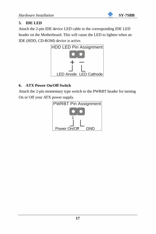
5. IDE LED
Attach the 2-pin IDE device LED cable to the corresponding IDE LED
header on the Motherboard. This will cause the LED to lighten when an
IDE (HDD, CD-ROM) device is active.
6. ATX Power On/Off Switch
Attach the 2-pin momentary type switch to the PWRBT header for turning
On or Off your ATX power supply.
HDD LED Pin Assignment
+ _
LED Anode LED Cathode
PWRBT Pin Assignment
Power On/Off GND
1
Hardware Installation SY-7SBB
18
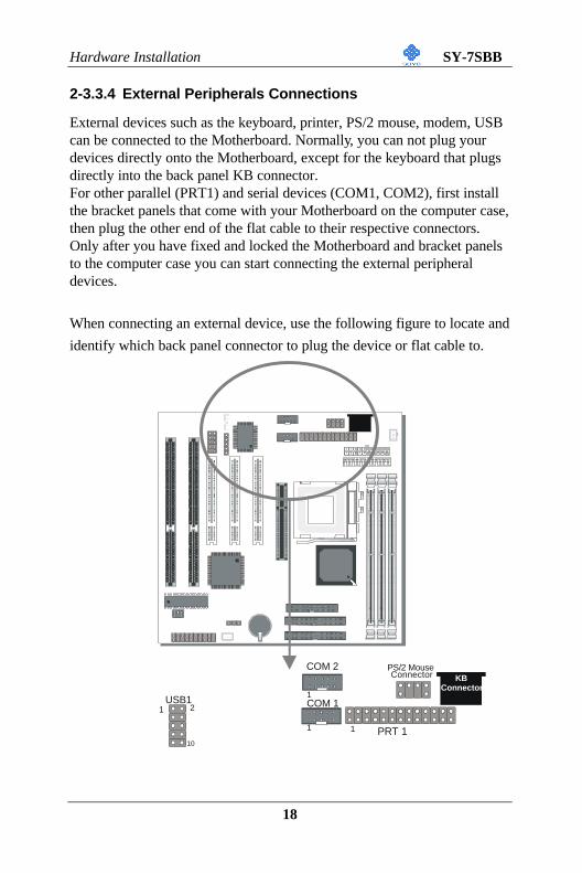
2-3.3.4 External Peripherals Connections
External devices such as the keyboard, printer, PS/2 mouse, modem, USBcan be connected to the Motherboard. Normally, you can not plug yourdevices directly onto the Motherboard, except for the keyboard that plugsdirectly into the back panel KB connector.For other parallel (PRT1) and serial devices (COM1, COM2), first installthe bracket panels that come with your Motherboard on the computer case,then plug the other end of the flat cable to their respective connectors.Only after you have fixed and locked the Motherboard and bracket panelsto the computer case you can start connecting the external peripheraldevices.
When connecting an external device, use the following figure to locate and
identify which back panel connector to plug the device or flat cable to.
1
*
22
PRT 1
KBConnector
PS/2 MouseConnector
1
COM 2
1
COM 11
21
10
USB1
Hardware Installation SY-7SBB
19
1. Serial Ports COM1/COM2
External Devices that use the COM ports include serial mice and modems.
The COM port connectors are located on 2 separate brackets panels, as
shown on the figure below. Please plug their respective 10 pin flat cable
connectors into the COM1 and COM 2 serial port connectors on the
Motherboard.
The bracket panels should be fixed to one of the slots at the back of the
computer case using a screw, after having finished this you can plug any
serial device into the back panel connectors.
Hardware Installation SY-7SBB
20
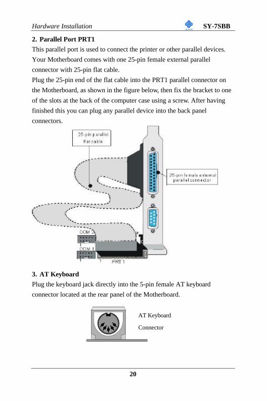
2. Parallel Port PRT1
This parallel port is used to connect the printer or other parallel devices.
Your Motherboard comes with one 25-pin female external parallel
connector with 25-pin flat cable.
Plug the 25-pin end of the flat cable into the PRT1 parallel connector on
the Motherboard, as shown in the figure below, then fix the bracket to one
of the slots at the back of the computer case using a screw. After having
finished this you can plug any parallel device into the back panel
connectors.
3. AT Keyboard
Plug the keyboard jack directly into the 5-pin female AT keyboard
connector located at the rear panel of the Motherboard.
AT Keyboard
Connector
Hardware Installation SY-7SBB
21
4. PS/2 Mouse
Attach the mouse cable to the 6-pin male PS/2 mouse connector on the
Motherboard to make use of a PS/2 mouse.
5. Universal Serial Bus (USB)
This Motherboard provides a dual-row 10-pin header (one pin is empty) to
support two USB ports for your additional devices. Attach the USB cable
(Optional) to this header as shown in the diagram below. The USB cable
has two USB ports mounted on a bracket.
PRT 1
KBConnector
PS/2 MouseConnector
1
COM 2
1
COM 11
Hardware Installation SY-7SBB
22
2-3.3.5 Other Connections
1. Wake-On-LAN (WOL)
Attach the 3-pin connector from a LAN card that supports the Wake-On-
LAN (WOL) function to the JP44 header on the Motherboard. This
WOL function lets users wake up the connected computer through the
LAN card.
Please install according to the following pin assignment:
Wake-On-LANJP44 Pin Assignment
MP-Wake-up
GND
5VSB1
2
3
Hardware Installation SY-7SBB
23
2. Infrared (IR1)
Plug the 5-pin infrared device cable to the IR1 header. This will enable the
infrared transfer function. This Motherboard meets both the ASKIR and
HPSIR specifications.
Please install according to the following pin assignment:
Serial Infrared (IR1) ConnectorIR1 Pin Assignment
1 2 3 4 5VCC
IRRXGND
IRTX
Hardware Installation SY-7SBB
24
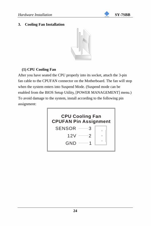
3. Cooling Fan Installation
(1) CPU Cooling Fan
After you have seated the CPU properly into its socket, attach the 3-pin
fan cable to the CPUFAN connector on the Motherboard. The fan will stop
when the system enters into Suspend Mode. (Suspend mode can be
enabled from the BIOS Setup Utility, [POWER MANAGEMENT] menu.)
To avoid damage to the system, install according to the following pin
assignment:
CPU Cooling FanCPUFAN Pin Assignment
SENSOR
12V
GND 1
3
2
Hardware Installation SY-7SBB
25
(2) Chassis Cooling Fan
Some cases also feature a cooling fan. This Motherboard features a
CHAFAN connector to provide 12V power to the chassis fan. Connect the
cable from the chassis fan to the CHAFAN 3-pin connector. Install
according to the following pin assignment:
2-3.3.6 PCI Audio Card
Some PCI soundcards require a PC-PCI DMA channel. Attach the 5-pin
cable from your PCI audio card to the SB-LINK ™ header on the
Motherboard. The SB-LINK ™ will forward requests for legacy DMA
channel to the PCI Bus.
Chassis Cooling FanCHAFAN Pin Assignment
SENSOR12VGND
1 32
1
2 5
6
4
DGND DGND
PC/PCI Request Sideband Signal
PC/PCI GrantSideband Signal
Serial IRQ
SB-LINK (PC/PCI)Pin Assignment
TM
Hardware Installation SY-7SBB
26
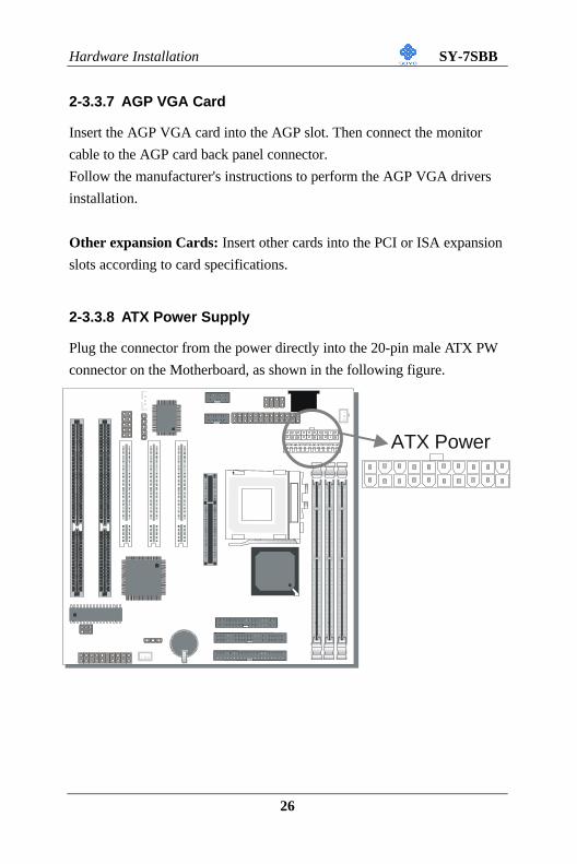
2-3.3.7 AGP VGA Card
Insert the AGP VGA card into the AGP slot. Then connect the monitor
cable to the AGP card back panel connector.
Follow the manufacturer's instructions to perform the AGP VGA drivers
installation.
Other expansion Cards: Insert other cards into the PCI or ISA expansion
slots according to card specifications.
2-3.3.8 ATX Power Supply
Plug the connector from the power directly into the 20-pin male ATX PW
connector on the Motherboard, as shown in the following figure.
1
*
22
ATX Power
Hardware Installation SY-7SBB
27
3.3V
-12V
GND
PS-ON
GND
GND
GND
-5V
5V
5V
3.3V
3.3V
GND
5V
GND
5V
GND
PW-OK
5VSB
12V
ATX Power
Warning: Follow these precautions to preserve your
Motherboard from any remnant currents when connecting to
ATX power supply:
Turn off the power supply and unplug the power cord of the
ATX power supply before connecting to ATX PW connector.
The Motherboard requires a power supply with at least 200 Watts and a
"power good" signal. Make sure the ATX power supply can take at least
720 mA * load on the 5V Standby lead (5VSB) to meet the standard ATX
specification.
* Note: If you use the Wake-On-LAN (WOL) function, the current
requirement is even more critical, make sure to use an ATX powersupply
that can at least supply 720mA on the 5STB line.
Please install the ATX power according to the following pin assignment:
Ø Pay special care to the notch.
Hardware Installation SY-7SBB
28
2-3.3.9 AT Power Supply
If you are using AT power, plug the dual 6-pin headers from the power
directly into the 12-pin male AT Power connector on the motherboard.
Make sure black leads of the 6-pin AT power headers are in the center.
Note: DO NOT use an AT powersupply if you already use an ATX
powersupply. Use only one type of powersupply at the same time.
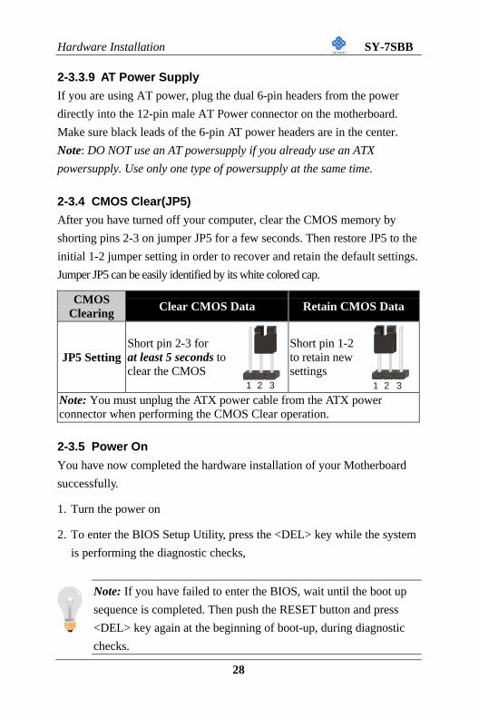
2-3.4 CMOS Clear(JP5)
After you have turned off your computer, clear the CMOS memory by
shorting pins 2-3 on jumper JP5 for a few seconds. Then restore JP5 to the
initial 1-2 jumper setting in order to recover and retain the default settings.
Jumper JP5 can be easily identified by its white colored cap.
CMOSClearing Clear CMOS Data Retain CMOS Data
JP5 SettingShort pin 2-3 forat least 5 seconds toclear the CMOS
Short pin 1-2to retain newsettings
Note: You must unplug the ATX power cable from the ATX powerconnector when performing the CMOS Clear operation.
2-3.5 Power On
You have now completed the hardware installation of your Motherboard
successfully.
1. Turn the power on
2. To enter the BIOS Setup Utility, press the <DEL> key while the system
is performing the diagnostic checks,
Note: If you have failed to enter the BIOS, wait until the boot up
sequence is completed. Then push the RESET button and press
<DEL> key again at the beginning of boot-up, during diagnostic
checks.
1 2 31 2 3
Hardware Installation SY-7SBB
29
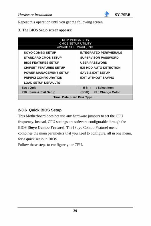
Repeat this operation until you get the following screen.
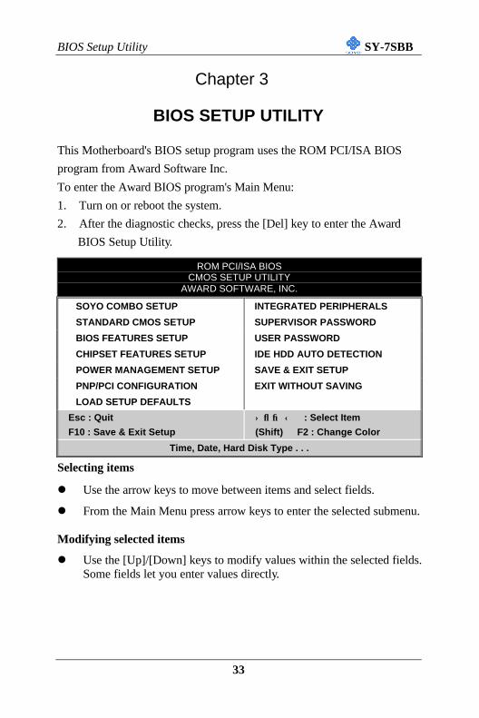
3. The BIOS Setup screen appears:
ROM PCI/ISA BIOSCMOS SETUP UTILITY
AWARD SOFTWARE, INC.
SOYO COMBO SETUP INTEGRATED PERIPHERALS
STANDARD CMOS SETUP SUPERVISOR PASSWORD
BIOS FEATURES SETUP USER PASSWORD
CHIPSET FEATURES SETUP IDE HDD AUTO DETECTION
POWER MANAGEMENT SETUP SAVE & EXIT SETUP
PNP/PCI CONFIGURATION EXIT WITHOUT SAVING
LOAD SETUP DEFAULTS
Esc : Quit ↑ ↓ → ← : Select Item
F10 : Save & Exit Setup (Shift) F2 : Change Color
Time, Date, Hard Disk Type . . .
2-3.6 Quick BIOS Setup
This Motherboard does not use any hardware jumpers to set the CPU
frequency. Instead, CPU settings are software configurable through the
BIOS [Soyo Combo Feature]. The [Soyo Combo Feature] menu
combines the main parameters that you need to configure, all in one menu,
for a quick setup in BIOS.
Follow these steps to configure your CPU.
Hardware Installation SY-7SBB
30
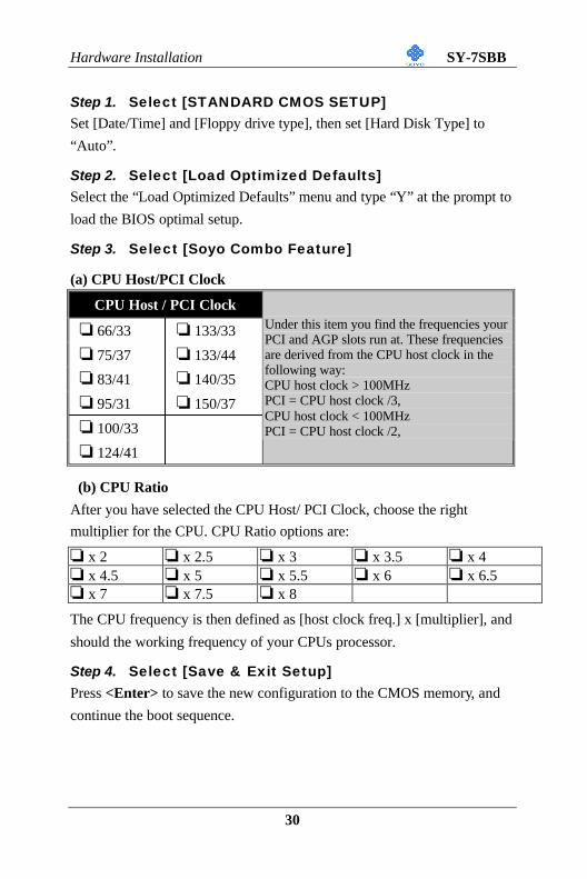
Step 1. Select [STANDARD CMOS SETUP]Set [Date/Time] and [Floppy drive type], then set [Hard Disk Type] to
“Auto”.
Step 2. Select [Load Optimized Defaults]Select the “Load Optimized Defaults” menu and type “Y” at the prompt to
load the BIOS optimal setup.
Step 3. Select [Soyo Combo Feature]
(a) CPU Host/PCI Clock
CPU Host / PCI Clock
o 66/33 o 133/33
o 75/37 o 133/44
o 83/41 o 140/35
o 95/31 o 150/37
o 100/33
o 124/41
Under this item you find the frequencies yourPCI and AGP slots run at. These frequenciesare derived from the CPU host clock in thefollowing way:CPU host clock > 100MHzPCI = CPU host clock /3,CPU host clock < 100MHzPCI = CPU host clock /2,
(b) CPU Ratio
After you have selected the CPU Host/ PCI Clock, choose the right
multiplier for the CPU. CPU Ratio options are:
o x 2 o x 2.5 o x 3 o x 3.5 o x 4o x 4.5 o x 5 o x 5.5 o x 6 o x 6.5o x 7 o x 7.5 o x 8
The CPU frequency is then defined as [host clock freq.] x [multiplier], and
should the working frequency of your CPUs processor.
Step 4. Select [Save & Exit Setup]Press <Enter> to save the new configuration to the CMOS memory, and
continue the boot sequence.
Hardware Installation SY-7SBB
31
2-3.7 Troubleshooting at First Start
l What should I do if the Motherboard refuses to start?
1. Check that all DIMM memory modules are inserted completely.
Sometimes a DIMM that is not inserted properly can cause boot
problems.
2. Check whether all Add-on cards have been inserted properly. Re-
insert the Add-on cards to make sure that they make proper contact
with the slots. Try removing all Add-on cards one by one to see
whether or not one of them is causing problems. (Switch the system
off before removing any of the cards.
3. Verify that speed settings are not exceeding specifications. This
applies to the PCI bus, that is specified to run at 33 MHz. Also check
the speed setting for the memory, make sure conservative setting. If
the CPU is overclocked the system may not start up, read the section
below.
4. Make sure that the Harddisk IDE cables are attached properly, if not
the system will not boot. In case of doubt try reversing the IDE
connector on one end of the cable.
5. Verify that the 110/220V switch on the back of the power supply is
set correctly.
6. Go through the jumper setting section again to make sure that all
jumpers are set correctly.
Note on Over-clocking Capability
The SY-7SBB provides over-clocking capability. If overclocked, your
system may fail to boot up or hang during run time. Please perform the
following steps to recover your system from the abnormal situation :
1. Turn off system power (If you use an ATX power supply, and
depending on your system, you may have to press the power button
for more than 4 seconds to shut down the system.)
2. Press and hold down the <Insert> key while turning on the system
Hardware Installation SY-7SBB
32
power. Keep holding down the <Insert> key until you see the CPU
type and frequency message shown on the screen.
3. Press the <Del> key during the system diagnostic checks to enter the
Award BIOS Setup program.
4. Select [Save & Exit SETUP] and press <Enter> to save the new
configuration to the CMOS memory, and continue the boot sequence.
Note: SOYO does not guarantee system stability if the user over
clocks the system. Any malfunctions due to over-clocking are not
covered by the warranty.
2-3.8 Power Off
There are two possible ways to turn off the system:
1. Use the Shutdown command in the Start Menu of Windows 95/98
to turn off your computer.
2. Press the mechanical power-button and hold down for over 4
seconds, to shutdown the computer. If you press the power-button for
less than 4 seconds, then your system will enter into Suspend Mode.
You are now ready to configure your system with the BIOS setup program.
Go to Chapter 3: BIOS SETUP
BIOS Setup Utility SY-7SBB
33
Chapter 3
BIOS SETUP UTILITY
This Motherboard's BIOS setup program uses the ROM PCI/ISA BIOS
program from Award Software Inc.
To enter the Award BIOS program's Main Menu:
1. Turn on or reboot the system.
2. After the diagnostic checks, press the [Del] key to enter the Award
BIOS Setup Utility.
ROM PCI/ISA BIOSCMOS SETUP UTILITY
AWARD SOFTWARE, INC.
SOYO COMBO SETUP INTEGRATED PERIPHERALS
STANDARD CMOS SETUP SUPERVISOR PASSWORD
BIOS FEATURES SETUP USER PASSWORD
CHIPSET FEATURES SETUP IDE HDD AUTO DETECTION
POWER MANAGEMENT SETUP SAVE & EXIT SETUP
PNP/PCI CONFIGURATION EXIT WITHOUT SAVING
LOAD SETUP DEFAULTS
Esc : Quit ↑ ↓ → ← : Select Item
F10 : Save & Exit Setup (Shift) F2 : Change Color
Time, Date, Hard Disk Type . . .
Selecting items
l Use the arrow keys to move between items and select fields.
l From the Main Menu press arrow keys to enter the selected submenu.
Modifying selected items
l Use the [Up]/[Down] keys to modify values within the selected fields.Some fields let you enter values directly.
BIOS Setup Utility SY-7SBB
34
Hot Keys: Function keys give you access to a group of commands
throughout the BIOS utility.Function Command Description
F1 Help Gives the list of options available for each item.
Shift F2 Color Change the color of the display window.
F5 Old values Restore the old values. These are the values that the userstarted the current session with.
F7 Load SetupDefaults
Loads all options with the Power-On default values.
F10 Save & ExitSetup
Saves your changes and reboots the system.
[Esc] Quit Lets you return at anytime and from any location to theMain Menu.
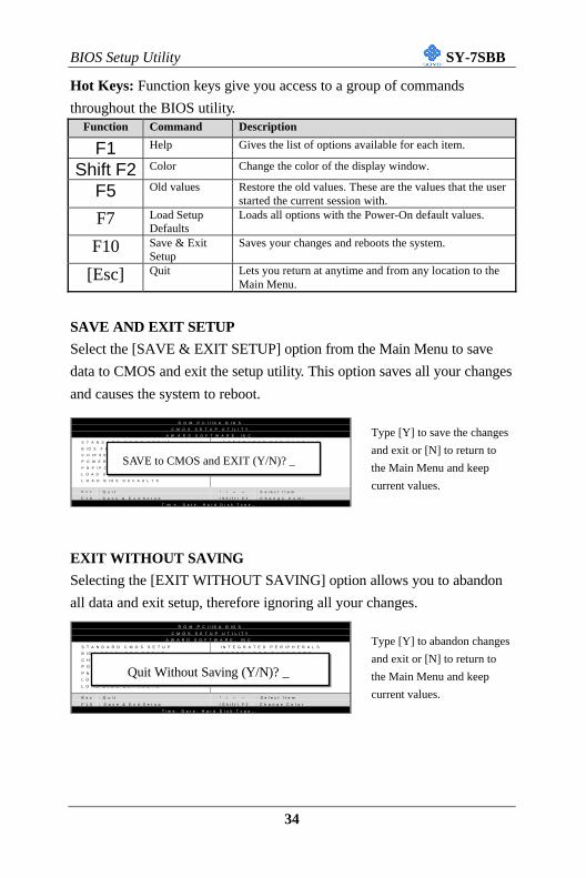
SAVE AND EXIT SETUP
Select the [SAVE & EXIT SETUP] option from the Main Menu to save
data to CMOS and exit the setup utility. This option saves all your changes
and causes the system to reboot.
Type [Y] to save the changes
and exit or [N] to return to
the Main Menu and keep
current values.
EXIT WITHOUT SAVING
Selecting the [EXIT WITHOUT SAVING] option allows you to abandon
all data and exit setup, therefore ignoring all your changes.
Type [Y] to abandon changes
and exit or [N] to return to
the Main Menu and keep
current values.
R O M P C I / I S A B I O S
C M O S S E T U P U T I L I T Y
A W A R D S O F T W A R E , I N C .
S T A N D A R D C M O S S E T U P
B I O S F E A T U R E S S E T U P
C H I P S E T F E A T U R E S S E T U P
P O W E R M A N A G E M E N T S E T U P
P N P / P C I C O N F I G U R A T I O N
L O A D S E T U P D E F A U L T S
L O A D B I O S D E F A U L T S
I N T E G R A T E D P E R I P H E R A L S
S U P E R V I S O R P A S S W O R D
U S E R P A S S W O R D
I D E H D D A U T O D E T E C T I O N
S A V E & E X I T S E T U P
E X I T W I T H O U T S A V I N G
E s c
F 1 0
: Q u i t
: S a v e & E x i t S e t u p
↑ ↓ → ←
( S h i f t ) F 2
: S e l e c t I t e m
: C h a n g e C o l o r
T i m e , D a t e , H a r d D i s k T y p e …
SAVE to CMOS and EXIT (Y/N)? _
R O M P C I / I S A B I O S
C M O S S E T U P U T I L I T Y
A W A R D S O F T W A R E , I N C .
S T A N D A R D C M O S S E T U P
B I O S F E A T U R E S S E T U P
C H I P S E T F E A T U R E S S E T U P
P O W E R M A N A G E M E N T S E T U P
P N P / P C I C O N F I G U R A T I O N
L O A D S E T U P D E F A U L T S
L O A D B I O S D E F A U L T S
I N T E G R A T E D P E R I P H E R A L S
S U P E R V I S O R P A S S W O R D
U S E R P A S S W O R D
I D E H D D A U T O D E T E C T I O N
S A V E & E X I T S E T U P
E X I T W I T H O U T S A V I N G
E s c
F 1 0
: Q u i t
: S a v e & E x i t S e t u p
↑ ↓ → ←
( S h i f t ) F 2
: S e l e c t I t e m
: C h a n g e C o l o r
T i m e , D a t e , H a r d D i s k T y p e …
Quit Without Saving (Y/N)? _
BIOS Setup Utility SY-7SBB
35
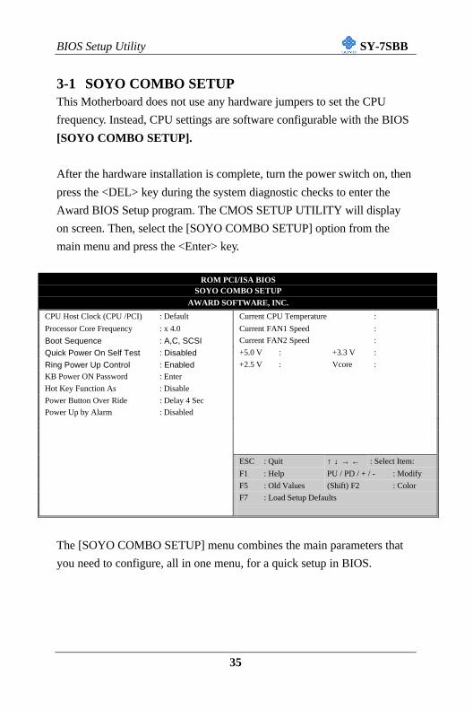
3-1 SOYO COMBO SETUPThis Motherboard does not use any hardware jumpers to set the CPU
frequency. Instead, CPU settings are software configurable with the BIOS
[SOYO COMBO SETUP].
After the hardware installation is complete, turn the power switch on, then
press the <DEL> key during the system diagnostic checks to enter the
Award BIOS Setup program. The CMOS SETUP UTILITY will display
on screen. Then, select the [SOYO COMBO SETUP] option from the
main menu and press the <Enter> key.
ROM PCI/ISA BIOSSOYO COMBO SETUP
AWARD SOFTWARE, INC.
CPU Host Clock (CPU /PCI) : Default Current CPU Temperature :
Processor Core Frequency : x 4.0 Current FAN1 Speed :
Boot Sequence : A,C, SCSI Current FAN2 Speed :
Quick Power On Self Test : Disabled +5.0 V : +3.3 V :
Ring Power Up Control : Enabled +2.5 V : Vcore :
KB Power ON Password : Enter
Hot Key Function As : Disable
Power Button Over Ride : Delay 4 Sec
Power Up by Alarm : Disabled
ESC : Quit ↑ ↓ → ← : Select Item:
F1 : Help PU / PD / + / - : Modify
F5 : Old Values (Shift) F2 : Color
F7 : Load Setup Defaults
The [SOYO COMBO SETUP] menu combines the main parameters that
you need to configure, all in one menu, for a quick setup in BIOS.
BIOS Setup Utility SY-7SBB
36
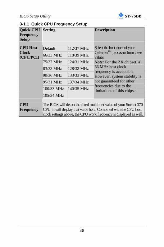
3-1.1 Quick CPU Frequency SetupQuick CPUFrequencySetup
Setting Description
Default 112/37 MHz
66/33 MHz 118/39 MHz
75/37 MHz 124/31 MHz
83/33 MHz 128/32 MHz
90/36 MHz 133/33 MHz
95/31 MHz 137/34 MHz
100/33 MHz 140/35 MHz
CPU HostClock(CPU/PCI)
105/34 MHz
Select the host clock of yourCeleronTM processor from thesevalues.Note: For the ZX chipset, a66 MHz host clockfrequency is acceptable.However, system stability isnot guaranteed for otherfrequencies due to thelimitations of this chipset.
CPUFrequency
The BIOS will detect the fixed multiplier value of your Socket 370CPU. It will display that value here. Combined with the CPU hostclock settings above, the CPU work frequency is displayed as well.
BIOS Setup Utility SY-7SBB
37
3-1.2 System Boot Control SettingsSystem BootControl Settings
Setting Description Note
A, C, SCSIC, A, SCSIC, CD-ROM, ACD-ROM, C, AD, A, SCSIE, A, SCSIF, A, SCSISCSI, A, CSCSI, C, AC only
Boot Sequence
LS/ZIP, C
Choose the boot sequenceadapted to your needs, forexample:l [A, C, SCSI] meansthe BIOS will look for anoperating system first indrive A, then in drive C,and eventually in the firstSCSI device.
Disabled DefaultQuick Power OnSelf Test Enabled Provides a fast POTS at
boot-up.
3-1.3 Power ManagementPM Events Setting Description Note
DisabledRing PowerUp Control Enabled When you select Enabled, a ring
signal from the modem returns thesystem to Full On state.
Default
KB Power ONPassword
Enter (yourpassword)
Set the password that will wake-up yoursystem.
BIOS Setup Utility SY-7SBB
38
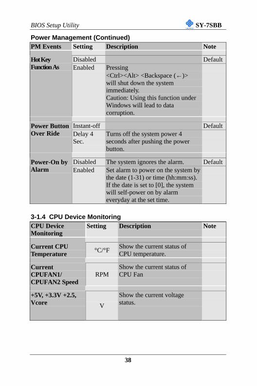
Power Management (Continued)PM Events Setting Description Note
Disabled DefaultHot KeyFunction As Enabled Pressing
<Ctrl><Alt> <Backspace (←)>will shut down the systemimmediately.Caution: Using this function underWindows will lead to datacorruption.
Instant-off DefaultPower ButtonOver Ride Delay 4
Sec.Turns off the system power 4seconds after pushing the powerbutton.
Disabled The system ignores the alarm. DefaultPower-On byAlarm Enabled Set alarm to power on the system by
the date (1-31) or time (hh:mm:ss).If the date is set to [0], the systemwill self-power on by alarmeveryday at the set time.
3-1.4 CPU Device MonitoringCPU DeviceMonitoring
Setting Description Note
Current CPUTemperature °C/°F
Show the current status ofCPU temperature.
CurrentCPUFAN1/CPUFAN2 Speed
RPMShow the current status ofCPU Fan
+5V, +3.3V +2.5,Vcore V
Show the current voltagestatus.
BIOS Setup Utility SY-7SBB
39
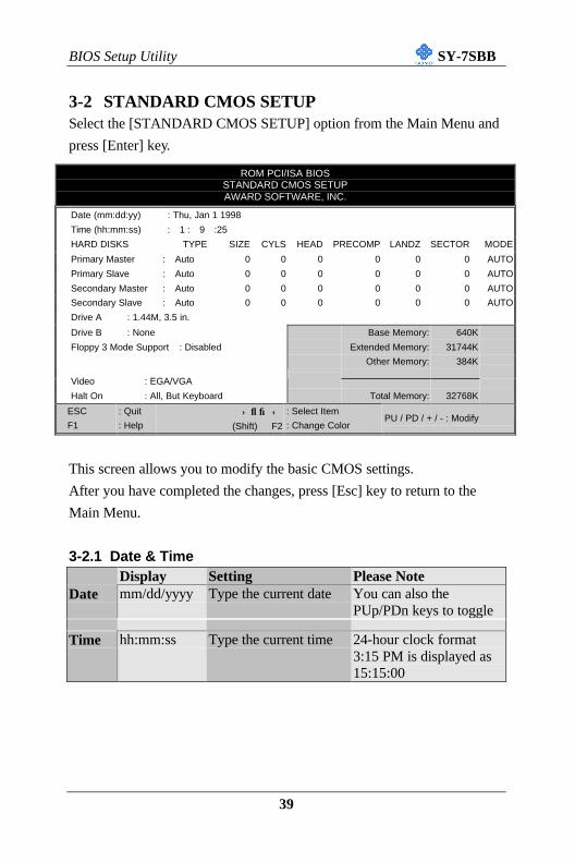
3-2 STANDARD CMOS SETUPSelect the [STANDARD CMOS SETUP] option from the Main Menu and
press [Enter] key.
ROM PCI/ISA BIOSSTANDARD CMOS SETUPAWARD SOFTWARE, INC.
Date (mm:dd:yy) : Thu, Jan 1 1998
Time (hh:mm:ss) : 1 : 9 :25
HARD DISKS TYPE SIZE CYLS HEAD PRECOMP LANDZ SECTOR MODE
Primary Master : Auto 0 0 0 0 0 0 AUTO
Primary Slave : Auto 0 0 0 0 0 0 AUTO
Secondary Master : Auto 0 0 0 0 0 0 AUTO
Secondary Slave : Auto 0 0 0 0 0 0 AUTO
Drive A : 1.44M, 3.5 in.
Drive B : None Base Memory: 640K
Floppy 3 Mode Support : Disabled Extended Memory: 31744K
Other Memory: 384K
Video : EGA/VGA
Halt On : All, But Keyboard Total Memory: 32768K
ESC : Quit ↑ ↓ → ← : Select Item
F1 : Help (Shift) F2 : Change ColorPU / PD / + / - : Modify
This screen allows you to modify the basic CMOS settings.
After you have completed the changes, press [Esc] key to return to the
Main Menu.
3-2.1 Date & TimeDisplay Setting Please Note
Date mm/dd/yyyy Type the current date You can also thePUp/PDn keys to toggle
Time hh:mm:ss Type the current time 24-hour clock format3:15 PM is displayed as15:15:00
BIOS Setup Utility SY-7SBB
40
3-2.2 Hard Disks Type & Mode
Choose the type and mode for the hard disks that you have already
installed.Primary(Secondary)Master & Slave
Setting Description Note
Auto BIOS detects hard disk typeautomatically.
Default
User User defines the type of hard disk.
Type
None
Auto BIOS detects hard disk modeautomatically.
Default
Normal Normal IDE hard disk <528MBLBA Enhanced IDE hard disk >528MB
Mode
Large Large IDE hard disk (for certainhard disk)
Note: If you have any questions on your hard disk type or mode, ask
Protection Enabled If set to enabled, the ParagonAnti-Virus. Function will scanyour boot drive for bootvirusses. If a boot virus isdetected, the BIOS will displaya warning message.
Choose how long after youpress a key the characterbegins repeating.
Default
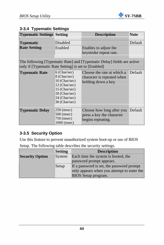
3-3.5 Security Option
Use this feature to prevent unauthorized system boot-up or use of BIOS
Setup. The following table describes the security settings.Setting DescriptionSystem Each time the system is booted, the
password prompt appears.Security Option
Setup If a password is set, the password promptonly appears when you attempt to enter theBIOS Setup program.
BIOS Setup Utility SY-7SBB
45
3-3.6 Other Control OptionsOther ControlOptions
Setting Description Note
Disabled DefaultEnabled
PCI/VGAPalette Snoop
The color of the monitor may be altered whenusing an MPEG card. Enable this option torestore the monitor's normal color.
DisabledAssign IRQFor VGA Enabled Use this default setting. Default
OS2 When using an OS2 operatingsystem.
OS Select forDRAM>64MB
Non-OS2 When using another,non-OS2 operating system.
Default
Disabled DefaultHDDS.M.A.R.T.capability
Enabled Enable this field when your HDDsupports the S.M.A.R.T. function.Consult your HDD provider fordetails.
Yes Windows will release IRQ line 6(normally used by the Floppy DiskDrive) after you disable your on-board FDD and set this field to[Yes].
DefaultReport NoFDD For WIN95
No Windows will reserve INT 6 foryour FDD, whether it is disabled ornot.
DisabledEnabled
Video orAdapter BIOSShadow The BIOS is shadowed in a 16K segment if it is
enabled and if it has BIOS present.These 16 segments can be shadowed fromROM to RAM. BIOS shadow copies BIOScode from slower ROM to faster RAM. BIOScan then execute from RAM.
Default
BIOS Setup Utility SY-7SBB
46
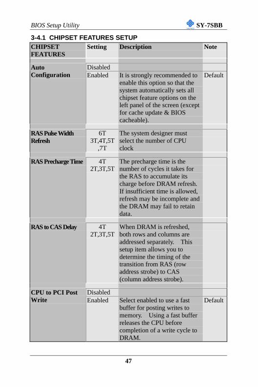
3-4 CHIPSET FEATURES SETUP
Caution: Change these settings only if you are already familiar
with the Chipset.
ROM PCI/ISA BIOS
CMOS SETUP UTILITY
CHIPSET FEATURES SETUP
Auto Configuration : Enabled AGP Aperture Size : 64RAS Pulse Width Refresh : 6T System BIOS Cacheable : EnabledRAS Precharge Time : 4T Video BIOS Cacheable : EnabledRAS to CAS Delay : 4T Memory Hole At 15M –16M : DisabledCPU to PCI Post Write : Enabled Concurrent function (MEM) : DisabledStarting Point of Paging : 1TECC Function for Bank 0 : Disabled CPU Pipeline Control : EnabledECC Function for Bank 1 : Disabled PCI Delay Transaction : DisabledECC Function for Bank 2 : Disabled Spread Spectrum : DisabledSDRAM CAS Latency : 2TSDRAM WR Retire Rate : X-1-1-1SDRAM Wait State Control : 0WSRAMW# Assertion Timing : 2TCAS Precharge Time (EDO) : 2TCAS# Pulse Width for EDO : 2TCAS Precharge Time (FP) : 2TCAS# Pulse Width for FP : 2TCPU to PCI Burst Mem_ WR : Enabled ESC : Quit ↑ ↓ → ← : Select ItemSDRAM Input Signals : Delay 0.5ns F1 : Help PU/PD/+/- : ModifySDRAM Output Signals : Lead 0.0ns F5 : Old Values (Shift) F2 : Color
F7 : Load Setup Defaults
The [CHIPSET FEATURES SETUP] option changes the values of the
chipset registers. These registers control the system options in the
computer.
After you have completed the changes, press [Esc] and follow the
instructions on your screen to save your settings or exit without saving.
The following table describes each field in the CHIPSET FEATURES
SETUP Menu and how to configure each parameter.
BIOS Setup Utility SY-7SBB
47
3-4.1 CHIPSET FEATURES SETUPCHIPSETFEATURES
Setting Description Note
DisabledAutoConfiguration Enabled It is strongly recommended to
enable this option so that thesystem automatically sets allchipset feature options on theleft panel of the screen (exceptfor cache update & BIOScacheable).
Default
RAS Pulse WidthRefresh
6T3T,4T,5T
,7T
The system designer mustselect the number of CPUclock
RAS Precharge Time 4T2T,3T,5T
The precharge time is thenumber of cycles it takes forthe RAS to accumulate itscharge before DRAM refresh.If insufficient time is allowed,refresh may be incomplete andthe DRAM may fail to retaindata.
RAS to CAS Delay 4T2T,3T,5T
When DRAM is refreshed,both rows and columns areaddressed separately. Thissetup item allows you todetermine the timing of thetransition from RAS (rowaddress strobe) to CAS(column address strobe).
DisabledCPU to PCI PostWrite Enabled Select enabled to use a fast
buffer for posting writes tomemory. Using a fast bufferreleases the CPU beforecompletion of a write cycle toDRAM.
Default
BIOS Setup Utility SY-7SBB
48
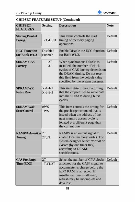
CHIPSET FEATURES SETUP (Continued)
CHIPSETFEATURES
Setting Description Note
Starting Point ofPaging
1T2T,4T,8T
This value controls the starttiming of memory pagingoperations.
Default
Disabled DefaultECC Functionfor Bank 0/1/2 Enabled
Enable/Disable the ECC functionfor Bank 0/1/2.
SDRAM CASLatency
2T3T
When synchronous DRAM isinstalled, the number of clockcycles of CAS latency depends onthe DRAM timing. Do not resetthis field from the default valuespecified by the system designer.
Default
X-1-1-1 DefaultSDRAM WRRetire Rate X-2-2-2
This item determines the timingthat the chipset uses to write datainto the SDRAM during burstcycles.
0WS DefaultSDRAM WaitState Control 1WS
This item controls the timing forthe precharge command that isissued when the address of thenext memory access cycle islocated at a different page thanthe current one.
2T DefaultRAMW# AssertionTiming 2T,3T
RAMW is an output signal toenable local memory writes. Thesystem designer select Normal orFaster (by one timer tick)according to DRAMspecifications.
2T DefaultCAS PrechargeTime (EDO) 1T,1T/2T
Select the number of CPU clocksallocated for the CAS# signal toaccumulate its charge before theEDO RAM is refreshed. Ifinsufficient time is allowed,refresh may be incomplete anddata lost.
BIOS Setup Utility SY-7SBB
49
CHIPSET FEATURES SETUP (Continued)
CHIPSETFEATURES
Setting Description Note
2T DefaultCAS# PulseWidth for EDO 0T,1T,
1T/2T
The system designer must setduration of a CAS signal pulse(in timer ticks).
2T DefaultCAS PrechargeTime (FP)
1T,1T/2T
This item allows you to selectCAS precharge time for FPRAM.
2T DefaultCAS# PulseWidth for FP
1T
The system designer must setduration of a CAS signal pulsefor FP RAM.
DisabledCPU to PCI BurstMem. WR Enabled Select enabled permits PCI
This item determines theDRAM input signal timing, inreference to the chipset CCLKsignal.
Lead 0.0 DefaultSDRAM outputSignals Delay
0.5/1.0/1.5/2.0/2.5
This item determines theDRAM output signal timing, inreference to the chipset CCLKsignal.
Disabled Use the default setting DefaultSDRAMPrechargeControl Enabled
AGP ApertureSize
644-256MB
AGP could use the DRAM asits video RAM. Choose theDRAM size that you wish toallocate as video RAM.
Default
BIOS Setup Utility SY-7SBB
50
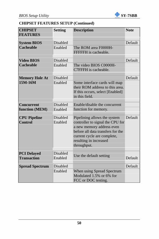
CHIPSET FEATURES SETUP (Continued)
CHIPSETFEATURES
Setting Description Note
Disabled DefaultSystem BIOSCacheable Enabled The ROM area F0000H-
FFFFFH is cacheable.
Disabled DefaultVideo BIOSCacheable Enabled The video BIOS C0000H-
C7FFFH is cacheable.
Disabled DefaultMemory Hole At15M-16M Enabled Some interface cards will map
their ROM address to this area.If this occurs, select [Enabled]in this field.
DisabledConcurrentfunction (MEM) Enabled
Enable/disable the concurrentfunction for memory.
CPU PipelineControl
DisabledEnabled
Pipelining allows the systemcontroller to signal the CPU fora new memory address evenbefore all data transfers for thecurrent cycle are complete,resulting in increasedthroughput.
Default
PCI DelayedTransaction
DisabledEnabled
Use the default settingDefault
Disabled DefaultSpread SpectrumEnabled When using Spread Spectrum
Modulated 1.5% or 6% forFCC or DOC testing.
BIOS Setup Utility SY-7SBB
51
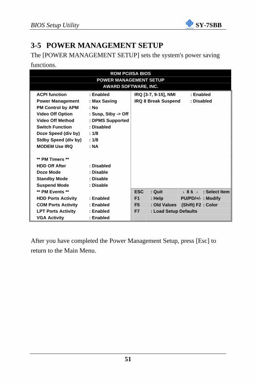
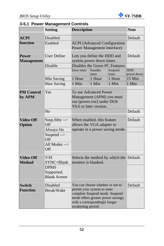
3-5 POWER MANAGEMENT SETUPThe [POWER MANAGEMENT SETUP] sets the system's power saving
functions.ROM PCI/ISA BIOS
POWER MANAGEMENT SETUPAWARD SOFTWARE, INC.
ACPI function : Enabled IRQ [3-7, 9-15], NMI : EnabledPower Management : Max Saving IRQ 8 Break Suspend : DisabledPM Control by APM : NoVideo Off Option : Susp, Stby -> OffVideo Off Method : DPMS SupportedSwitch Function : DisabledDoze Speed (div by) : 1/8Stdby Speed (div by) : 1/8MODEM Use IRQ : NA
User Define Lets you define the HDD andsystem power down times.
Default
Disable Disables the Green PC Features.Doze timer Standby
timerSuspendtimer
HDDpower down
Min Saving 1 Hour 1 Hour 1 Hour 15 Min
PowerManagement
Max Saving 1 Min 1 Min 1 Min 1 Min
Yes To use Advanced PowerManagement (APM) you mustrun [power.exe] under DOSV6.0 or later version.
PM Controlby APM
No Default
Susp,Stby -->Off
Default
Always OnSuspend -->Off
Video OffOption
All Modes -->Off
When enabled, this featureallows the VGA adapter tooperate in a power saving mode.
V/HSYNC+Blank
DefaultVideo OffMethod
DPMSSupported,Blank Screen
Selects the method by which themonitor is blanked.
Disabled DefaultSwitchFunction Break/Wake
You can choose whether or not topermit your system to entercomplete Suspend mode. Suspendmode offers greater power savings,with a correspondingly longerawakening period.
BIOS Setup Utility SY-7SBB
53
Power Management Controls (Continued)Setting Description Note
1/8 DefaultDoze Speed(div by) 1~8
Sets the CPU's speed during Dozemode. The speed is reduced to afraction of the CPU's normal speed.The divisors range from 1 to 8
1/8 DefaultStdby Speed(div by) 1~8
Select a divisor to reduce the CPUspeed during Standby mode to afraction of the full CPU speed. Thespeed is reduced to a fraction of theCPU's normal speed. The divisorsrange from 1 to 8-0.
3 DefaultMODEM UseIRQ 3-11, NA
Assigns an IRQ# to the modemdevice.
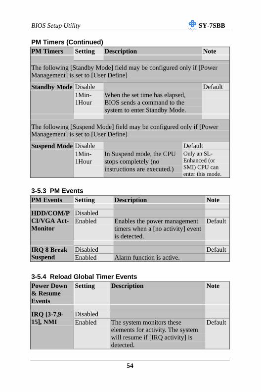
3-5.2 PM TimersPM Timers Setting Description Note
The following [HDD Off After] field may be configured only if [PowerManagement] is set to [User Define]
Disabled DefaultHDD OffAfter 1Min-
15Min
By default, this item is Disabled,meaning that no matter what mode therest of the system is in, the hard drivewill remain ready. Otherwise, you havea range of choices from 1 to 15 minutesor Suspend. This means that you canelect to have your hard disk drive to beturned off after a selected number ofminutes or when the rest of the systemgoes into Suspend mode.
The following [Doze Mode] field may be configured only if [PowerManagement] is set to [User Define]
Disable DefaultDoze Mode1Min-1Hour
When the set time has elapsed,BIOS sends a command to thesystem to enter Doze Mode.
Legacy ISA Choose IRQ-# andDMA-# assigned toLegacy ISA card.
IRQ-3,4,5,7,9,10,11,12,14,15
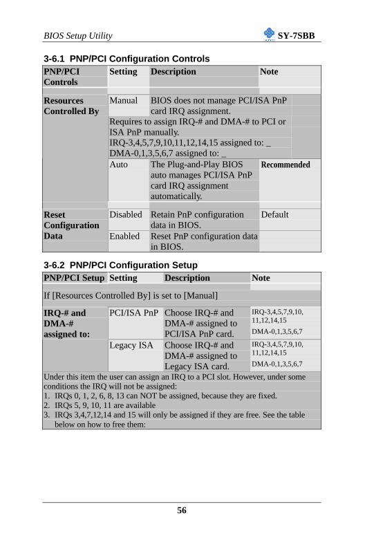
DMA-0,1,3,5,6,7
Under this item the user can assign an IRQ to a PCI slot. However, under someconditions the IRQ will not be assigned:1. IRQs 0, 1, 2, 6, 8, 13 can NOT be assigned, because they are fixed.2. IRQs 5, 9, 10, 11 are available3. IRQs 3,4,7,12,14 and 15 will only be assigned if they are free. See the table
How to set the BIOS to release the IRQ to the PnP Interrupt pool:InterruptLine PnP / PCI configuration Integrated PeripheralsIRQ 15 IRQ 15: PCI / ISA PnP On-Chip Secondary PCI IDE: disabledIRQ 14 IRQ 14: PCI / ISA PnP On-Chip Primary PCI IDE: disabled
IRQ 12 IRQ 12: PCI / ISA PnPInterrupt 12 will be released by the PnPBIOS automatically if the PS/2 Mouse Portis not used.
IRQ 7 IRQ 7: PCI / ISA PnP Onboard parallel port: disabledIRQ 4 IRQ 4: PCI / ISA PnP Onboard Serial port 1: disabledIRQ 3 IRQ 3: PCI / ISA PnP Onboard Serial port 2: disabled4. Your OS may reassign another interrupt to a PCI slot after BIOS passes control
to the OS, especially if you use Windows 95, 98 or NT.Level DefaultPCI IRQ
Actived By EdgeThis sets the method by which thePCI bus recognizes that an IRQservice is being requested by adevice. Under all circumstances,you should retain the defaultconfiguration unless advisedotherwise by your system’smanufacturer.
PCI-AUTO
DefaultPCI IDE IRQMap To
ISA,Optional
This allows you to configure yoursystem to the type of IDE diskcontroller in use. By default, Setupassumes that your controller is an ISA(Industry Standard Architecture)device rather than a PCI controller.The more apparent difference is thetype of slot being used.
A DefaultPrimary/Secondary IDEINT#
B, C, DIf you have equipped your system witha PCI controller, changing this allowsyou to specify which slot has thecontroller and which PCI interrupt (A,B, C or D) is associated with theconnected hard drives
Enabled BIOS will assign IRQ for USBport.
DefaultAssign IRQ ForUSB
Disabled BIOS won’t assign IRQ for USBport.
BIOS Setup Utility SY-7SBB
58
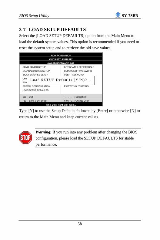
3-7 LOAD SETUP DEFAULTSSelect the [LOAD SETUP DEFAULTS] option from the Main Menu to
load the default system values. This option is recommended if you need to
reset the system setup and to retrieve the old save values.
Type [Y] to use the Setup Defaults followed by [Enter] or otherwise [N] to
return to the Main Menu and keep current values.
Warning: If you run into any problem after changing the BIOS
configuration, please load the SETUP DEFAULTS for stable
performance.
ROM PCI/ISA BIOS
CMOS SETUP UTILITY
AWARD SOFTWARE, INC.
SOYO COMBO SETUP
STANDARD CMOS SETUP
BIOS FEATURES SETUP
CHIPSET FEATURES SETUP
POWER MANAGEMENT SETUP
PNP/PCI CONFIGURATION
LOAD SETUP DEFAULTS
INTEGRATED PERIPHERALS
SUPERVISOR PASSWORD
USER PASSWORD
IDE HDD AUTO DETECTION
SAVE & EXIT SETUP
EXIT WITHOUT SAVING
Esc
F10
: Quit
: Save & Exit Setup
↑ ↓ → ←
(Shift) F2
: Select Item
: Change Color
Time, Date, Hard Disk Type…
L o a d S E T U P D e f a u l t s ( Y / N ) ? _
BIOS Setup Utility SY-7SBB
59
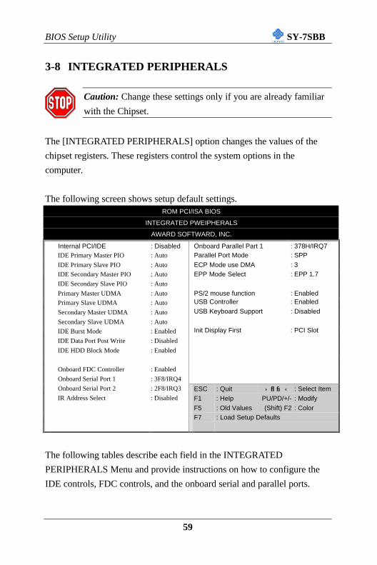
3-8 INTEGRATED PERIPHERALS
Caution: Change these settings only if you are already familiar
with the Chipset.
The [INTEGRATED PERIPHERALS] option changes the values of the
chipset registers. These registers control the system options in the
computer.
The following screen shows setup default settings.ROM PCI/ISA BIOS
INTEGRATED PWEIPHERALS
AWARD SOFTWARD, INC.
Internal PCI/IDE : Disabled Onboard Parallel Part 1 : 378H/IRQ7IDE Primary Master PIO : Auto Parallel Port Mode : SPP
IDE Primary Slave PIO : Auto ECP Mode use DMA : 3IDE Secondary Master PIO : Auto EPP Mode Select : EPP 1.7
IDE Secondary Slave PIO : Auto
Primary Master UDMA : Auto PS/2 mouse function : EnabledPrimary Slave UDMA : Auto USB Controller : Enabled
Secondary Master UDMA : Auto USB Keyboard Support : Disabled
Secondary Slave UDMA : Auto
IDE Burst Mode : Enabled Init Display First : PCI Slot
IDE Data Port Post Write : Disabled
IDE HDD Block Mode : Enabled
Onboard FDC Controller : Enabled
Onboard Serial Port 1 : 3F8/IRQ4
Onboard Serial Port 2 : 2F8/IRQ3 ESC : Quit ↑ ↓ → ← : Select ItemIR Address Select : Disabled F1 : Help PU/PD/+/- : Modify
Init Display First PCI Slot Choose which card –AGP Display card or PCIVGA card – to initializefirst.
Default
BIOS Setup Utility SY-7SBB
63
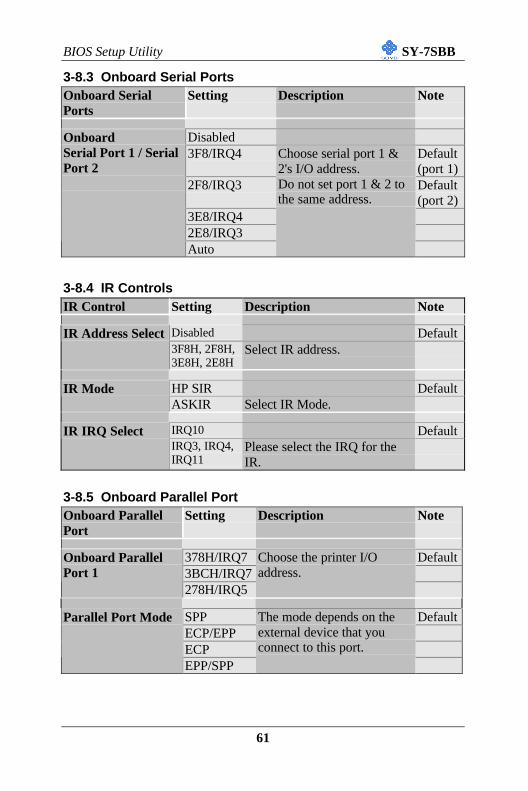
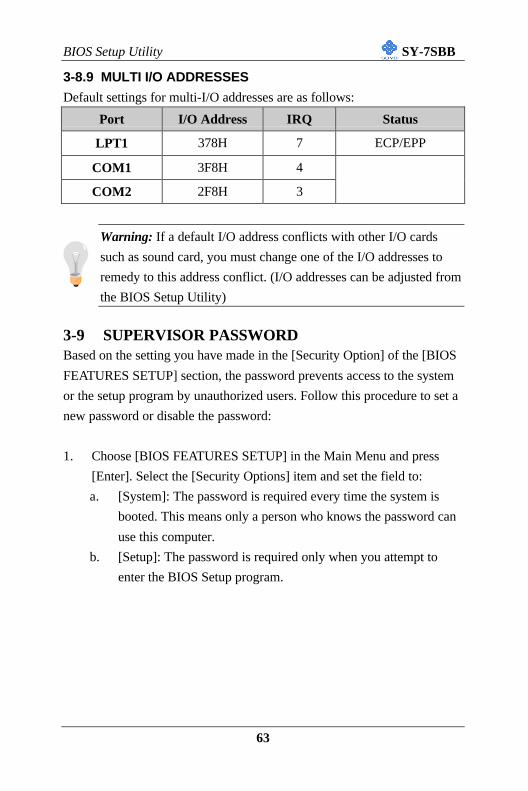
3-8.9 MULTI I/O ADDRESSES
Default settings for multi-I/O addresses are as follows:
Port I/O Address IRQ Status
LPT1 378H 7 ECP/EPP
COM1 3F8H 4
COM2 2F8H 3
Warning: If a default I/O address conflicts with other I/O cards
such as sound card, you must change one of the I/O addresses to
remedy to this address conflict. (I/O addresses can be adjusted from
the BIOS Setup Utility)
3-9 SUPERVISOR PASSWORDBased on the setting you have made in the [Security Option] of the [BIOS
FEATURES SETUP] section, the password prevents access to the system
or the setup program by unauthorized users. Follow this procedure to set a
new password or disable the password:
1. Choose [BIOS FEATURES SETUP] in the Main Menu and press
[Enter]. Select the [Security Options] item and set the field to:
a. [System]: The password is required every time the system is
booted. This means only a person who knows the password can
use this computer.
b. [Setup]: The password is required only when you attempt to
enter the BIOS Setup program.
BIOS Setup Utility SY-7SBB
64
2. Choose [SUPERVISOR PASSWORD] from the Main Menu and
press [Enter]. The following prompt will appear:
Warning: If you forget or lose the password, the only way toaccess the system is to set jumper JP5 to clear the CMOS RAM.All setup information is lost and you must run the BIOS setupprogram again.
Note: If you do not wish to use the password function, press[Enter] directly and the following message appears:
3. Enter your new password and press [Enter]. The following message
appears, prompting to confirm the new password:
4. Re-enter your password and then press [Enter] to exit to the MainMenu.
Enter Password:
Password Disabled!!
Confirm Password:
BIOS Setup Utility SY-7SBB
65
This diagram outlines the password selection procedure:
3-10 USER PASSWORDWhen the user password option is on, you are not allowed to change any
setting in the [CMOS SETUP UTILITY] except for changing the user's
password.
The password setting procedure is similar to that for the [SUPERVISOR
PASSWORD] (Refer to section 3-9).
ROM PCI/ISA BIOS
CMOS SETUP UTILITY
AWARD SOFTWARE, INC.
STANDARD CMOS SETUP
BIOS FEATURES SETUP
CHIPSET FEATURES SETUP
POWER MANAGEMENT SETUP
PNP/PCI CONFIGURATION
LOAD SETUP DEFAULTS
LOAD BIOS DEFAULTS
INTEGRATED PERIPHERALS
SUPERVISOR PASSWORD
USER PASSWORD
IDE HDD AUTO DETECTION
SAVE & EXIT SETUP
EXIT WITHOUT SAVING
Esc
F10
: Quit
: Save & Exit Setup
↑ ↓ → ←
(Shift) F2
: Select Item
: Change Color
Time, Date, Hard Disk Type…
Enter Password:
Enter Password: ∗ ∗ ∗ ∗ ∗ Password Disabled!!
Confirm Password: ∗ ∗ ∗ ∗ ∗
Press: ↔Without entering password
Type the Password
Press: ↔
After you confirm the
password, press ° to exit
Type the Passwordand Press: <Enter>
Press <Enter> withoutentering the password
After you confirm the password,press <Esc> to exit
BIOS Setup Utility SY-7SBB
66
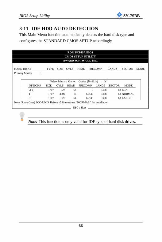
3-11 IDE HDD AUTO DETECTIONThis Main Menu function automatically detects the hard disk type and
configures the STANDARD CMOS SETUP accordingly.
ROM PCI/ISA BIOS
CMOS SETUP UTILITY
AWARD SOFTWARE, INC.
HARD DISKS TYPE SIZE CYLS HEAD PRECOMP LANDZ SECTOR MODE
Primary Master :
Select Primary Master Option (N=Skip) : N
OPTIONS SIZE CYLS HEAD PRECOMP LANDZ SECTOR MODE
2(Y) 1707 827 64 0 3308 63 LBA
1 1707 3309 16 65535 3308 63 NORMAL
3 1707 827 64 65535 3308 63 LARGE
Note: Some Oses( SCO-UNIX Before v5.0) must use “NORMAL” for installation
Note: This function is only valid for IDE type of hard disk drives.
ESC : Skip
The SOYO CD SY-7SBB
67
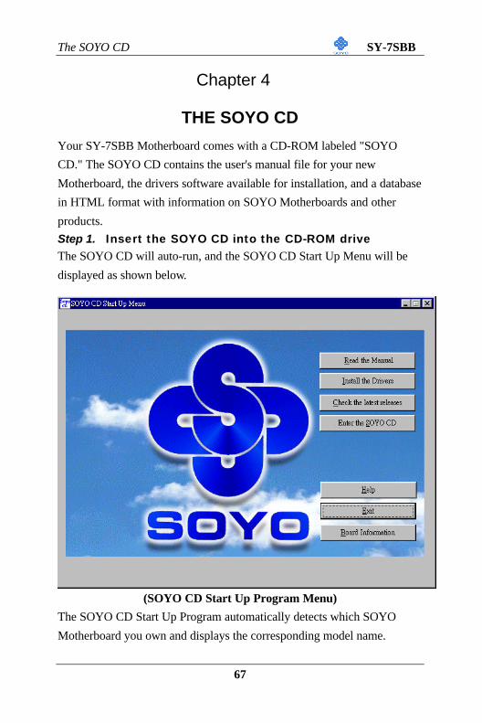
Chapter 4
THE SOYO CD
Your SY-7SBB Motherboard comes with a CD-ROM labeled "SOYO
CD." The SOYO CD contains the user's manual file for your new
Motherboard, the drivers software available for installation, and a database
in HTML format with information on SOYO Motherboards and other
products.
Step 1. Insert the SOYO CD into the CD-ROM driveThe SOYO CD will auto-run, and the SOYO CD Start Up Menu will be
displayed as shown below.
(SOYO CD Start Up Program Menu)
The SOYO CD Start Up Program automatically detects which SOYO
Motherboard you own and displays the corresponding model name.
The SOYO CD SY-7SBB
68
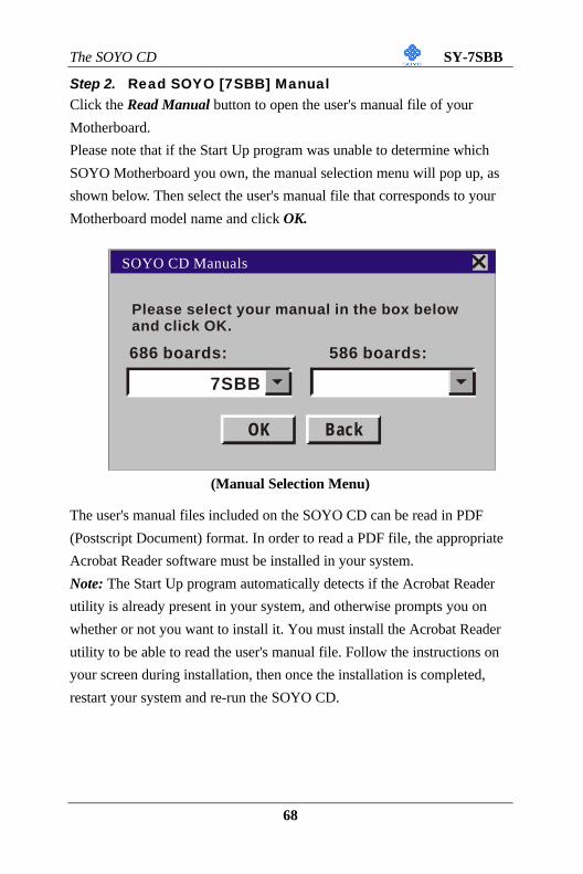
Step 2. Read SOYO [7SBB] ManualClick the Read Manual button to open the user's manual file of your
Motherboard.
Please note that if the Start Up program was unable to determine which
SOYO Motherboard you own, the manual selection menu will pop up, as
shown below. Then select the user's manual file that corresponds to your
Motherboard model name and click OK.
(Manual Selection Menu)
The user's manual files included on the SOYO CD can be read in PDF
(Postscript Document) format. In order to read a PDF file, the appropriate
Acrobat Reader software must be installed in your system.
Note: The Start Up program automatically detects if the Acrobat Reader
utility is already present in your system, and otherwise prompts you on
whether or not you want to install it. You must install the Acrobat Reader
utility to be able to read the user's manual file. Follow the instructions on
your screen during installation, then once the installation is completed,
restart your system and re-run the SOYO CD.
SOYO CD Manuals
Please select your manual in the box belowand click OK.
686 boards: 586 boards:
OK Back
7SBB
The SOYO CD SY-7SBB
69
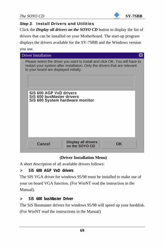
Step 3. Install Drivers and UtilitiesClick the Display all drivers on the SOYO CD button to display the list of
drivers that can be installed on your Motherboard. The start-up program
displays the drivers available for the SY-7SBB and the Windows version
you use.
(Driver Installation Menu)
A short description of all available drivers follows:
Ø SiS 600 AGP VxD drivers
The SIS VGA driver for windows 95/98 must be installed to make use of
your on board VGA function. (For WinNT read the instruction in the
Manual).
Ø SiS 600 busMaster Driver
The SiS Busmaster drivers for windows 95/98 will speed up your harddisk.
(For WinNT read the instructions in the Manual)
Please select the driver you want to install and click OK, You will have to restart your system after installation. Only the drivers that are relevant to your board are displayed initially.
Use this utility to deep track of the system hardware parameters. (For
Windows 95/98)
Select which driver you want to install and click OK, or click Cancel toreturn to the main menu. When the installation program of a driver startsrunning the SOYO-CD will exit. After finishing the installation, restart theSOYO-CD and install the next driver. We recommend you to install alldrivers, and to do so in the right sequence (top to bottom).
Step 5. Check the Latest ReleasesClick the 'Check the latest Releases' button to go the SOYO Website to
automatically find the latest BIOS, manual and driver releases for your
motherboard. This button will only work if your computer is connected to
the internet through a network or modem connection. Make sure to get
your modem connection up before clicking this button.
The SOYO CD SY-7SBB
71
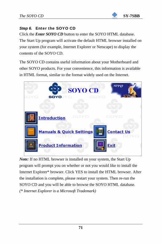
Step 6. Enter the SOYO CDClick the Enter SOYO CD button to enter the SOYO HTML database.
The Start Up program will activate the default HTML browser installed on
your system (for example, Internet Explorer or Netscape) to display the
contents of the SOYO CD.
The SOYO CD contains useful information about your Motherboard and
other SOYO products. For your convenience, this information is available
in HTML format, similar to the format widely used on the Internet.
Note: If no HTML browser is installed on your system, the Start Up
program will prompt you on whether or not you would like to install the
Internet Explorer* browser. Click YES to install the HTML browser. After
the installation is complete, please restart your system. Then re-run the
SOYO CD and you will be able to browse the SOYO HTML database.


![INDEX [zarzuragricola.com.br]zarzuragricola.com.br/catalogo.pdf · layflat coupler - male camlock adapter x hose tail Ø 2" x 2" 354-183200 7.60 1 Ø 3" x 3" 354-183300 10.00 1 Ø](https://static.documents.pub/doc/80x56/606f7b60ea327d5cb35cb11c/index-layflat-coupler-male-camlock-adapter-x-hose-tail-2-x-2.jpg)


