U.S. TSUBAKI POWER-LOCK ® D-85 Technical Notes U.S. TSUBAKI POWER-LOCK ® .................... D-86 ~ D-90 (1) Maximum Torque and Maximum Thrust (2) Selection by Series • AS, AD, ADN, AE, FL, KE, RE, EF, TF Series • SL Series • EL Series ...................... D-91 ~ D-94 • AS, AD, ADN, AE, FL, KE, TF, EF Series • AS-SS, KE-SS, RE-SS, SL Series • EL Series .................. D-95 ~ D-96 1. Installing to Keyed Shafts 2. Installation Accuracy 3. Hub’s Outer Diameter Deformation 4. Ambient Temperature 5. Allowable Deviation of Tightening Torque MA 6. Hub Movement 7. Assembly Lubrication 8. Bending Moment 9. Outdoor Use Note: AD series is referred to as ADN and AD-N in other parts of the world. All three describe an identical product.
STEP 1 Actual Locking Force, Transmissible Torque and Contact Pressure
EL SeriesSTEP 1 Shaft and Hub
SL Series
U.S. TSUBAKI POWER-LOCK®
D-89
D - P
T COM
PONE
NTS
Technical NotesSELECTION GUIDE AND PROCEDURE
STEP 2EL Series POWER-LOCKs do not have a self-centering
function. A hub must be pre-centered, using the guide portion
provided between the shaft and hub. A guide portion length
above d/2 is generally preferred. Also, select guide tolerance
based on the degree of accuracy you desire.
(1) Material StrengthSelect shaft and hub materials that meet the following
strength requirements.
(2) Required Hub Outer Diameter DN and Allowable Hollow Shaft Bore Diameter dB
Hubs must have a that is greater than the value obtained
from the following formula.
If using a hollow shaft, its bore must be equivalent to or less
than the obtained from the appropriate formula below.
(a) Bolts Fastened to the Hub Section
Shaft and Hub
(1) Bolt Strength Classes and Mechanical PropertiesIn general, 10.9 and 12.9 class bolts should be used. These
bolts are less affected by vibration and do not loosen as
easily as others.
(2) Bolt Head Bearing Surface PressureWhen using 10.9 or 12.9 bolts, check the pressure at their
bearing surfaces. If this pressure exceeds the maximum
values provided below, the bearing surfaces will eventually
deform, causing the bolts to loosen from decreased axial
force. When the bearing pressure rises above the maximum
values, reduce by increasing the strength of pressure flange
(either change the material or treat with heat) or by lowering
the tightening torque in order to prevent the bearing surfaces
from deforming.
(b) Bolts Fastened to the Shaft Section
P, P´ : Contact pressure on the shaft and hub.
STEP 3 Selecting Locking Bolts
D-90
D - P
T COM
PONE
NTS
SELECTION GUIDE AND PROCEDURE
Pressure flanges experience a great deal of stress while
locking bolts are being tightened. To avoid plastic deformation,
use a pressure flange with the appropriate material strength
and provide enough leeway in the design to account for some
stress. Provided below are example pressure system design
and calculations.
See table on the right for and dimensions.
(1) Bolt Pitch Circle Diameter
When
However, if you are mounting a pressure flange to the hub, use
1/2 of the maximum number of bolts allowed or less, so that
they may fit into the circumference.
(2) Thickness of Pressure Flange
(3) Strength of Pressure Flange
When tightening with the torque required for 8.8 bolts.
42,600 psi (1035 steel)
When tightening with the torque required for 10.9 bolts.
49,700 psi (1045 steel)
When tightening with the torque required for 12.9 bolts.
56,900 psi (1055 steel)
Yield point of pressure flange
(4) Functioning Length of the Screw
STEP 4 Pressure System DesignsModel Number
Dimension X (mm)
No. of EL installed
Pressure Sleeve Diameters
(mm)
1 2 3 4 d1 D1
PL010X013E 2 2 3 3 10.1 12.9
PL011X014E 2 2 3 3 11.1 13.9
PL012X015E 2 2 3 3 12.1 14.9
PL013X016E 2 2 3 3 13.1 15.9
PL014X018E 3 3 4 5 14.1 17.9
PL015X019E 3 3 4 5 15.1 18.9
PL016X020E 3 3 4 5 16.1 19.9
PL017X021E 3 3 4 5 17.1 20.9
PL018X022E 3 3 4 5 18.1 21.9
PL019X024E 3 3 4 5 19.2 23.8
PL020X025E 3 3 4 5 20.2 24.8
PL022X026E 3 3 4 5 22.2 25.8
PL024X028E 3 3 4 5 24.2 27.8
PL025X030E 3 3 4 5 25.2 29.8
PL028X032E 3 3 4 5 28.2 31.8
PL030X035E 3 3 4 5 30.2 34.8
PL032X036E 3 3 4 5 32.2 35.8
PL035X040E 3 3 4 5 35.2 39.8
PL036X042E 3 3 4 5 36.2 41.8
PL038X044E 3 3 4 5 38.2 43.8
PL040X045E 3 4 5 6 40.2 44.8
PL042X048E 3 4 5 6 42.2 47.8
PL045X052E 3 4 5 6 45.2 51.8
PL048X055E 3 4 5 6 48.2 54.8
PL050X057E 3 4 5 6 50.2 56.8
PL055X062E 3 4 5 6 55.2 61.8
PL056X064E 3 4 5 7 56.2 63.8
PL060X068E 3 4 5 7 60.2 67.8
PL063X071E 3 4 5 7 63.2 70.8
PL065X073E 3 4 5 7 65.2 72.8
PL070X079E 3 5 6 7 70.3 78.7
PL071X080E 3 5 6 7 71.3 79.7
PL075X084E 3 5 6 7 75.3 83.7
PL080X091E 4 5 6 8 80.3 90.7
PL085X096E 4 5 6 8 85.3 95.7
PL090X101E 4 5 6 8 90.3 100.7
PL095X106E 4 5 6 8 95.3 105.7
PL100X114E 4 6 7 9 100.3 113.7
PL110X124E 4 6 7 9 110.3 123.7
PL120X134E 4 6 7 9 120.3 133.7
PL130X148E 5 7 9 11 130.4 147.6
PL140X158E 5 7 9 11 140.4 157.6
PL150X168E 5 7 9 11 140.4 167.6
NOTE: Dimension X plus 3-mm is the minimum Pressure Sleeve length.
U.S. TSUBAKI POWER-LOCK®
D-91
D - P
T COM
PONE
NTS
Technical NotesAS, AD, ADN, AE, FL, KE, TF, EF Series Installation and Removal
A. Installation(1) Verify that the shaft and the inner surface of the hub are
clean, we recommend to lightly oil surfaces.
Note: Do not use silicone or molybdenum lubricants. Otherwise, friction coefficient will reduce, and standard torque will not be achieved.
(2) Remove the bolts and clean all contact surfaces. Lightly coat the bolts, including their bearing surfaces, with oil or grease. For AD/ADN Series POWER-LOCKs, use an oil bath or a spray method to thoroughly lubricate each part.
(3) Tighten the bolts part way, and preliminarily assemble the POWER-LOCK.
Notes: 1. Pre-assemble by keeping the phases of the slit and the taps for removal out of synch. For AD/ADN Series, maintain maximum space between the taper rings.
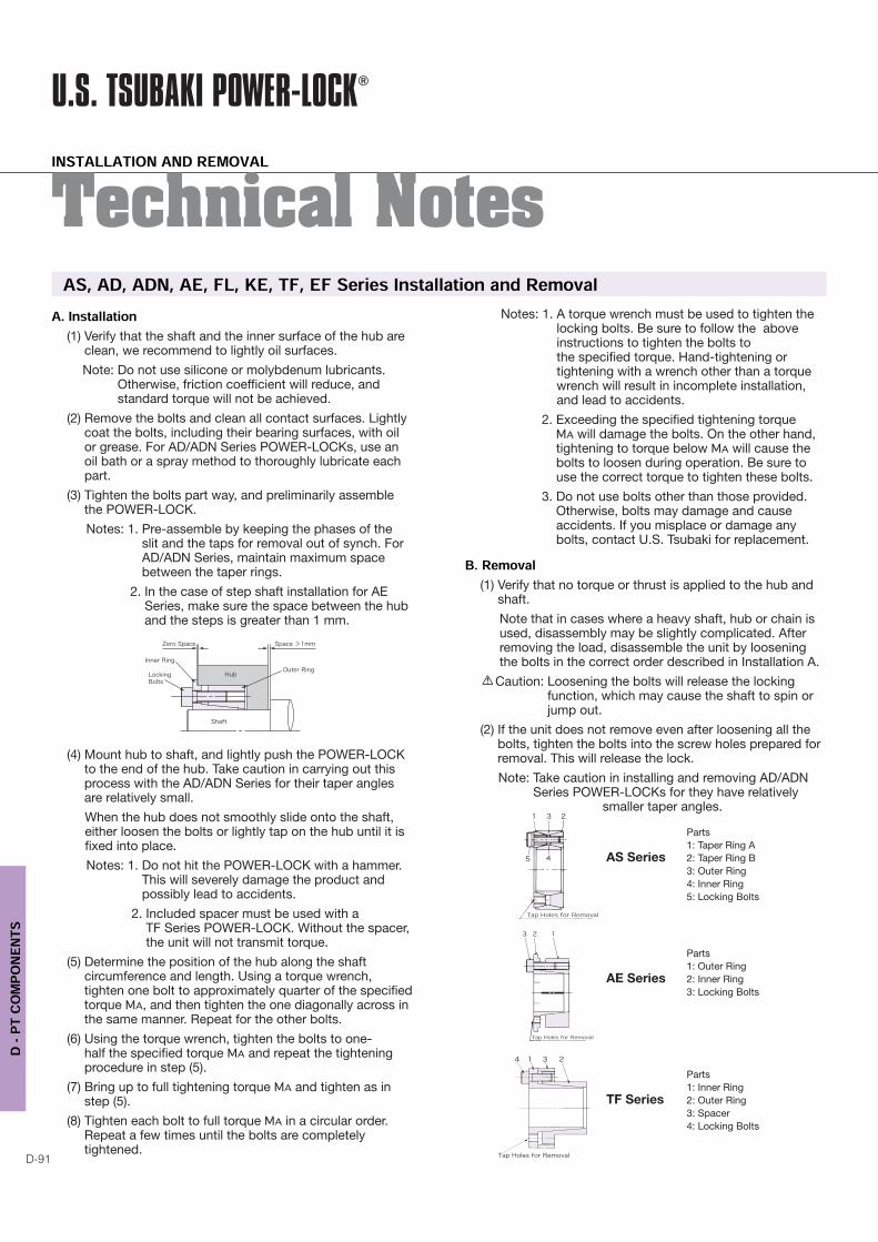
2. In the case of step shaft installation for AE Series, make sure the space between the hub and the steps is greater than 1 mm.
(4) Mount hub to shaft, and lightly push the POWER-LOCK to the end of the hub. Take caution in carrying out this process with the AD/ADN Series for their taper angles are relatively small.
When the hub does not smoothly slide onto the shaft, either loosen the bolts or lightly tap on the hub until it is fixed into place.
Notes: 1. Do not hit the POWER-LOCK with a hammer. This will severely damage the product and possibly lead to accidents.
2. Included spacer must be used with a TF Series POWER-LOCK. Without the spacer, the unit will not transmit torque.
(5) Determine the position of the hub along the shaft circumference and length. Using a torque wrench, tighten one bolt to approximately quarter of the specified torque , and then tighten the one diagonally across in the same manner. Repeat for the other bolts.
(6) Using the torque wrench, tighten the bolts to one-half the specified torque and repeat the tightening procedure in step (5).
(7) Bring up to full tightening torque and tighten as in step (5).
(8) Tighten each bolt to full torque in a circular order. Repeat a few times until the bolts are completely tightened.
Notes: 1. A torque wrench must be used to tighten the locking bolts. Be sure to follow the above instructions to tighten the bolts to the specified torque. Hand-tightening or tightening with a wrench other than a torque wrench will result in incomplete installation, and lead to accidents.
2. Exceeding the specified tightening torque will damage the bolts. On the other hand,
tightening to torque below will cause the bolts to loosen during operation. Be sure to use the correct torque to tighten these bolts.
3. Do not use bolts other than those provided. Otherwise, bolts may damage and cause accidents. If you misplace or damage any bolts, contact U.S. Tsubaki for replacement.
B. Removal(1) Verify that no torque or thrust is applied to the hub and
shaft.
Note that in cases where a heavy shaft, hub or chain is used, disassembly may be slightly complicated. After removing the load, disassemble the unit by loosening the bolts in the correct order described in Installation A.
Caution: Loosening the bolts will release the locking function, which may cause the shaft to spin or jump out.
(2) If the unit does not remove even after loosening all the bolts, tighten the bolts into the screw holes prepared for removal. This will release the lock.
Note: Take caution in installing and removing AD/ADN Series POWER-LOCKs for they have relatively
smaller taper angles.
Parts
1: Taper Ring A
AS Series 2: Taper Ring B
3: Outer Ring
4: Inner Ring
5: Locking Bolts
Parts
1: Outer Ring
AE Series 2: Inner Ring
3: Locking Bolts
Parts
1: Inner Ring
TF Series 2: Outer Ring
3: Spacer
4: Locking Bolts
INSTALLATION AND REMOVAL
D-92
D - P
T COM
PONE
NTS
A. Installation(1) Remove dust and oil from the hub and shaft with a cloth
or alcohol. Be sure to completely remove any grease and oil. Otherwise, standard torque may not be achieved.
Note: The locking bolts are coated with a special substance so no lubrication is required.
(2) Mount the POWER-LOCK onto the hub or shaft. Loosen the bolts or nut if difficult to install.
(3) Using a torque wrench, tighten the bolts at quarter of the specified torque , starting with one bolt then another diagonally across and repeating for the other bolts. Then, tighten the bolts further to one-half the specified torque in the same crisscross sequence. Finally, tighten each bolt to full torque in a circular order. Repeat until each bolt is completely tightened.
Notes: 1. Do not hit the POWER-LOCK with a hammer. This will severely damage the product and possibly lead to accidents.
2. A torque wrench must be used to tighten the locking bolts. Be sure to follow the above instructions to tighten the bolts to the specified torque. Hand-tightening or tightening with a wrench other than a torque wrench will result in incomplete installation, and lead to accidents.
3. Exceeding the specified tightening torque will damage the bolts. On the other hand,
tightening to torque below will cause the bolts to loosen during operation. Be sure to use the correct torque to tighten these bolts.
4. Do not use bolts or nuts other than those provided. Otherwise, bolts and nuts may damage and lead to accidents.
Notes on RE Series(1) Installation A: With a Snap Ring
Use a snap ring to prevent the hub from moving in the direction of the thrust.
(2) Installation B: Without a Snap Ring
The hub will move in the direction of the thrust while the unit is being installed. See RE Series Movement in the Shaft Direction for amount of hub movement.
Compared to Installation A, installation without a snap ring can transmit torque up to 1.7 times. Take note of the hub and shaft material strengths for this installation. The contact pressure generated at the hub and shaft from this setup is much larger than that achieved from Installation A. It is very important to check the hub material strength, for if the contact pressure is too high, the hub may displace itself. For required hub diameters, refer to the appropriate Hub Diameters table.
C. Reusability
Assembly and disassembly of the POWER-LOCKs may be repeated a few times. However, if the hub and shaft material yield stresses cannot tolerate the contact pressure P and P', repeated assembly and disassembly may damage certain parts of the hub-shaft contact surfaces.
Parts
1: Inner Ring
KE Series 2: Outer Ring
3: Locking Bolts
Parts
1: Taper Ring A
AD Series 2: Taper Ring B
3: Outer Ring
4. Inner Ring
5. Locking Bolts
Parts
1: Inner Ring
EF Series 2: Outer Ring
3: Locking Bolts
AS-SS, AS-KP, KE-SS, KE-KP, TF-KP, RE-SS, SL Installation and Removal
INSTALLATION AND REMOVAL
U.S. TSUBAKI POWER-LOCK®
D-93
D - P
T COM
PONE
NTS
Technical NotesThe snap ring can be easily removed with a flat-blade screwdriver.
• Removing a snap ring:
The snap rings for POWER-LOCKs are shaped like spirals. Insert a flat-blade screwdriver in the slit of the snap ring and slightly lift to remove. See Illustration 1.
Notes on SL Series
Before installing an SL POWER-LOCK, loosen the locking bolts and remove the spacer inserted between the taper rings A and B. See Illustration 2.
B. Removal(1) Verify that no torque or thrust is applied to the hub and
shaft.
Note that in cases where a heavy shaft, hub or chain is used, disassembly may be slightly complicated. After removing the load, disassemble the unit by loosening the bolts in the correct order described in Installation A.
Caution: Loosening the bolts will release the locking function, which may cause the shaft to spin or jump out.
(2) If the unit does not remove even after loosening all the bolts, tighten the bolts into the screw holes prepared for removal. This will instantly release the lock.
C. Reusability(1) When POWER-LOCKs with specially lubricated bolts
and inner rings start to flake, they cannot be reused. Also, if the end of a locking bolt seems to be damaged or if other parts show signs of wear, the product cannot be reused.
(2) Assembly and disassembly of the POWER-LOCKs may be repeated a few times. However, if the hub and shaft material yield stresses cannot tolerate the contact pressure P and P', repeated assembly and disassembly may damage certain parts of the hub-shaft contact surfaces.
SL Series1: Taper Ring A
2: Taper Ring B
3: Inner Ring
4. Locking Bolts
RE Series1: Inner Ring
2: Outer Ring
3: Locking Bolts
4. Snap Ring
INSTALLATION AND REMOVAL
D-94
D - P
T COM
PONE
NTS
A. Removal
(1) Verify that the shaft and the inner surface of the hub are clean, we recommend to lightly oil surfaces.
Note: Do not use silicone or molybdenum lubricants. Otherwise, friction coefficient will reduce, and standard torque will not be achieved.
(2) If an indentation in the inner hub corner or a large R is machined, a spacer sleeve must be used.
(3) An EL POWER-LOCK can be installed in two ways, resulting in different transmissible torque: (a) Install by pressurizing the outer ring or (b) by pressurizing the inner ring. Pay close attention to the installation position during this procedure.
(4) Mount the POWER-LOCK so that it slightly moves in parallel to the shaft.
(5) Mount by tightening the bolts on the pressure flange evenly, in a crisscross sequence. Make sure that the amount of space between the pressure flange and the hub is uniform throughout the circumference.
Note: If the pressure flange material strength is insufficient, adequate pressure cannot be achieved. Confirm the catalog rate for pressure flange material strength before installing and avoid damages to the POWER-LOCK and the bolt head bearing surfaces.
(6) Hand-tighten the bolts until the pressure flange no longer moves in the shaft direction. Then, adjust the hub position and phase.
Note: Do not use a spring washer or toothed washer with the pressure flange and bolts.
(7) Using a torque wrench or a hexagonal spanner wrench tighten the bolts to approximately quarter of the specified torque.
(8) Using the wrench tighten the bolts to one-half the specified torque.
(9) Bring up to full tightening torque until the bolts do not turn any further. Use the torque wrench to complete this final step and make sure that the space between the pressure flange and the hub or shaft end is uniform throughout the circumference.
Notes on AS and EL Series
When using a POWER-LOCK that is not self-centering, mount a guiding unit to the hub. Do not center by tightening the bolts. Instead, center or align the hub and shaft by adjusting the guide portion itself. The alignment accuracy is determined by the length and tolerance of the guide portion.
B. Removal(1) Tighten the bolts in a crisscross sequence.
Normally, when the bolts are loosened, the POWER-LOCK will remove itself.
(2) If it does not remove after loosening all the bolts, clean the surrounding surface and lightly hit the POWER-LOCK with a hammer.
(3) If an EL POWER-LOCK does not remove by procedure (2), an increase in friction coefficient may have taken place due to damaged contact surfaces or a dislocation of the unit may have happened due to incorrect mounting or a plastic deformation may have occurred. In these cases, the unit must be disassembled and the problem investigated before reassembling.
C. Reusability(1) An EL POWER-LOCK cannot be reused if the bolts or
other parts are damaged.
(2) Assembly and disassembly of the POWER-LOCKs may be repeated a few times. However, if the hub and shaft material yield stresses cannot tolerate the contact pressure P and P', repeated assembly and disassembly may damage certain parts of the hub-shaft contact surfaces.
EL Installation and Removal
INSTALLATION AND REMOVAL
U.S. TSUBAKI POWER-LOCK®
D-95
D - P
T COM
PONE
NTS
Technical Notes
1. Installing to Keyed Shafts Mounting to keyed shafts such as motored shafts will reduce the transmissible torque and transmissible thrust by 10%.
2. Installation Accuracy When a POWER-LOCK is installed into a straight hub bore, the installation accuracy depends on the hub's length as shown below.
3. Hub's Outer Diameter Deformation
When a POWER-LOCK is mounted onto a hub, contact
pressure P' will exert on the hub's inner surface, causing the
hub's outer diameter to experience a plastic deformation.
The specific degree of deformation cannot be determined
for it depends on the distribution of P' and the type of hub.
However, the following formula can be used to obtain rough
deformation values.
4. Ambient Temperature
POWER-LOCKs must be operated in an appropriate
environment with a temperature ranging from -22ºF to 392ºF.
5. Allowable Deviation of Tightening Torque MAThe allowable deviation from the specified tightening torque
is ±5%. If the bolts are correctly tightened within this range
with a torque wrench as instructed, the unit should achieve
adequate transmissible torque and thrust .
6. Hub MovementThe hub may move, depending on the type of POWER-LOCK
installed. See Selection and Procedure for details.
(1) RE Series Hub Movement
The hub will move when installing an RE POWER-LOCK
without a snap ring. This movement is caused
by the deformation of the shaft and hub and varies
depending on the hub's inner-to-outer diameter ratio aN.
See table below.
Model Number
Hub Movement
inch
aN=3 a
N=2 a
N=1.5
PL005X018 RE-SS 0.002 0.003 0.004
PL006X019 RE-SS 0.002 0.003 0.004
PL008X021 RE-SS 0.003 0.004 0.005
PL010X026 RE-SS 0.004 0.005 0.007
PL011X027 RE-SS 0.005 0.006 0.007
PL012X028 RE-SS 0.006 0.007 0.009
PL014X030 RE-SS 0.006 0.007 0.001
PL015X031 RE-SS 0.006 0.007 0.001
PL016X032 RE-SS 0.006 0.007 0.001
PL017X033 RE-SS 0.006 0.007 0.009
PL018X034 RE-SS 0.006 0.007 0.009
PL019X035 RE-SS 0.007 0.009 0.012
PL020X039 RE-SS 0.009 0.011 0.015
PL022X041 RE-SS 0.009 0.011 0.015
PL024X043 RE-SS 0.012 0.014 0.019
PL025X044 RE-SS 0.012 0.014 0.019
PL028X049 RE-SS 0.013 0.015 0.021
PL030X050 RE-SS 0.013 0.016 0.021
PL032X052 RE-SS 0.013 0.015 0.021
PL035X058 RE-SS 0.015 0.018 0.024
PL038X060 RE-SS 0.017 0.020 0.028
PL040X063 RE-SS 0.017 0.020 0.028
PL042X066 RE-SS 0.019 0.023 0.031
PL045X068 RE-SS 0.020 0.023 0.031
PL048X072 RE-SS 0.022 0.026 0.035
PL050X075 RE-SS 0.022 0.026 0.035
Series
ADN
AE
RE
KE
TF
EF
Hub Length B
L
L2
L2
L2
AS and EL are not self-centering.
Refer to Selection Procedure for details.
Note: Following contains metric numbers and equations. If there are questions, contact U.S. Tsubaki.
Precautions
PRECAUTIONS
D-96
D - P
T COM
PONE
NTS
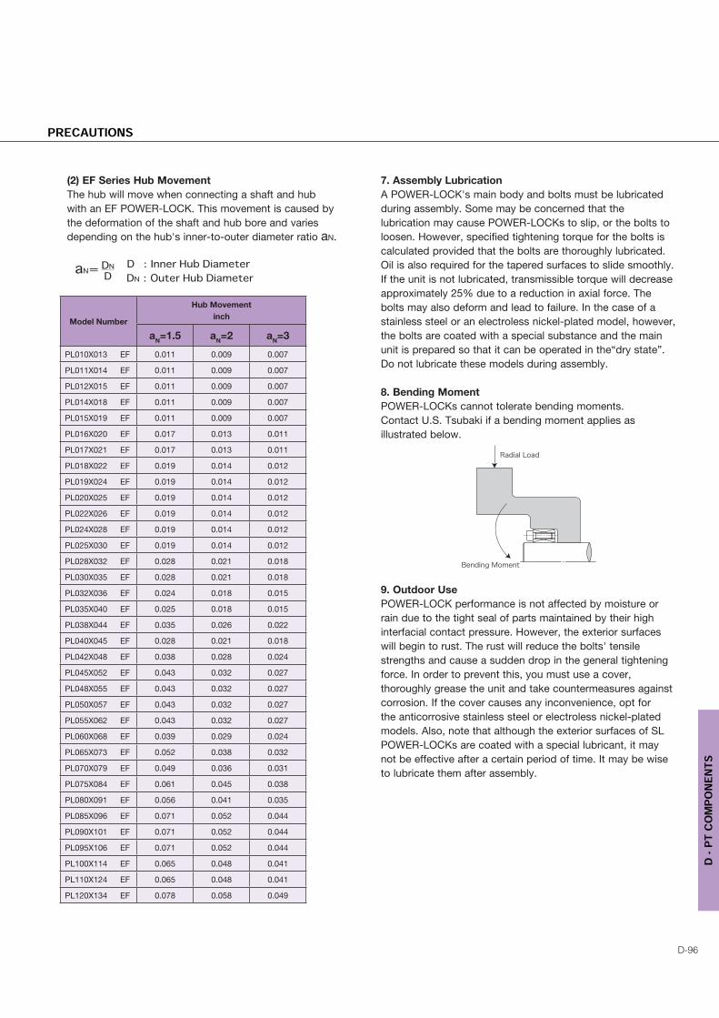
(2) EF Series Hub Movement
The hub will move when connecting a shaft and hub
with an EF POWER-LOCK. This movement is caused by
the deformation of the shaft and hub bore and varies
depending on the hub's inner-to-outer diameter ratio aN.
7. Assembly Lubrication
A POWER-LOCK's main body and bolts must be lubricated
during assembly. Some may be concerned that the
lubrication may cause POWER-LOCKs to slip, or the bolts to
loosen. However, specified tightening torque for the bolts is
calculated provided that the bolts are thoroughly lubricated.
Oil is also required for the tapered surfaces to slide smoothly.
If the unit is not lubricated, transmissible torque will decrease
approximately 25% due to a reduction in axial force. The
bolts may also deform and lead to failure. In the case of a
stainless steel or an electroless nickel-plated model, however,
the bolts are coated with a special substance and the main
unit is prepared so that it can be operated in the“dry state”.
Do not lubricate these models during assembly.
8. Bending Moment
POWER-LOCKs cannot tolerate bending moments.
Contact U.S. Tsubaki if a bending moment applies as
illustrated below.
9. Outdoor Use
POWER-LOCK performance is not affected by moisture or
rain due to the tight seal of parts maintained by their high
interfacial contact pressure. However, the exterior surfaces
will begin to rust. The rust will reduce the bolts' tensile
strengths and cause a sudden drop in the general tightening
force. In order to prevent this, you must use a cover,
thoroughly grease the unit and take countermeasures against
corrosion. If the cover causes any inconvenience, opt for
the anticorrosive stainless steel or electroless nickel-plated
models. Also, note that although the exterior surfaces of SL
POWER-LOCKs are coated with a special lubricant, it may
not be effective after a certain period of time. It may be wise