265
The XMOS XS1 Architecture David May
The XMOS XS1 Architecture
David May
ii The XMOS XS1 Architecture
The XMOS XS1 Architectureby David May
The authors have taken care in the preparation of this book, but make no expressed or implied warranty of anykind and assume no responsibility for errors or omissions. No liability is assumed for direct, indirect, incidentialor consequential damages in connection with or arising out of the use of the information or programs containedherein. No representation is made that the information or programs are or will be free from any claims ofinfringement and again, the authors shall have no liability in relation to any such claims.
Copyright © 2009 by XMOS Limited.Cover photo by Jason Mayes, copyright © 2009 by XMOS Limited.
All rights reserved. No part of this publication may be reproduced, stored in a retrieval system, or transmittedin any form, or by any means, electronic, mechanical, photocopying, recording, or otherwise, without the priorwritten permission of the publisher.
Trademarks: XMOS and the XMOS logo are registered trademarks of XMOS Limited in the United Kingdomand other countries, and may not be used without written permission. All other trademarks are property oftheir respective owners. Where those designations appear in this book, and XMOS was aware of a trademarkclaim, the designations have been printed with initial capital letters or in all capitals.
XMOS also publishes its books in electronic formats. Some content that appears in print may not be availablein electronic books.
For information on XMOS products, visit us on the Web: www.xmos.com.
Because of the dynamic nature of the Internet, any Web addresses or links contained in this book may havechanged since publication and may no longer be valid.
Printed and bound by CPI Antony Rowe, Chippenham.
ISBN: 978-1-907361-01-2 (PBK)ISBN: 978-1-907361-04-3
Published by XMOS Limited.
Contents iii
Contents
1 Background 1
2 Interconnect 12.1 XMOS Link Ports . . . . . . . . . . . . . . . . . . . . . . . . . . . . . . . 32.2 Serial XMOS Link . . . . . . . . . . . . . . . . . . . . . . . . . . . . . . . 32.3 Fast XMOS Link . . . . . . . . . . . . . . . . . . . . . . . . . . . . . . . . 4
3 Concurrent Threads 5
4 The XCore Instruction Set 6
5 Instruction Issue and Execution 85.1 Scheduler Implementation . . . . . . . . . . . . . . . . . . . . . . . . . . 9
6 Instruction Set Notation and Definitions 116.1 Instruction Prefixes . . . . . . . . . . . . . . . . . . . . . . . . . . . . . . 11
7 Data Access 12
8 Expression Evaluation 14
9 Branching, Jumping and Calling 15
10 Resources and the Thread Scheduler 16
11 Concurrency and Thread Synchronisation 18
12 Communication 21
13 Locks 24
14 Timers and Clocks 24
15 Ports, Input and Output 2615.1 Input and Output . . . . . . . . . . . . . . . . . . . . . . . . . . . . . . . . 2615.2 Port Configuration . . . . . . . . . . . . . . . . . . . . . . . . . . . . . . . 2715.3 Configuring Ready and Clock Signals . . . . . . . . . . . . . . . . . . . . 2915.4 NOREADY mode . . . . . . . . . . . . . . . . . . . . . . . . . . . . . . . 2915.5 HANDSHAKEN mode . . . . . . . . . . . . . . . . . . . . . . . . . . . . . 2915.6 STROBED mode . . . . . . . . . . . . . . . . . . . . . . . . . . . . . . . 3015.7 The Port Timer . . . . . . . . . . . . . . . . . . . . . . . . . . . . . . . . . 30
iv The XMOS XS1 Architecture
15.8 Conditions . . . . . . . . . . . . . . . . . . . . . . . . . . . . . . . . . . . 3115.9 Synchronised Transfers . . . . . . . . . . . . . . . . . . . . . . . . . . . . 3115.10 Buffered Transfers . . . . . . . . . . . . . . . . . . . . . . . . . . . . . . . 3215.11 Partial Transfers . . . . . . . . . . . . . . . . . . . . . . . . . . . . . . . . 3415.12 Changing Direction . . . . . . . . . . . . . . . . . . . . . . . . . . . . . . 34
16 Events, Interrupts and Exceptions 35
17 Initialisation and Debugging 41
18 Specialised Instructions 42
19 Instruction Details 4519.1 Instructions . . . . . . . . . . . . . . . . . . . . . . . . . . . . . . . . . . . 4519.2 Instruction Format Specification . . . . . . . . . . . . . . . . . . . . . . . 22619.3 Exceptions . . . . . . . . . . . . . . . . . . . . . . . . . . . . . . . . . . . 247

2 Interconnect 1
1 Background
An XS1 combines a number of XCore processors, each with its own memory, on a singlechip. The programmable processors are general purpose in the sense that they canexecute languages such as C; they also have direct support for concurrent processing(multi-threading), communication and input-output. A high-performance switch supportscommunication between the processors, and inter-chip XMOS Links are provided so thatsystems can easily be constructed from multiple chips.
The XS1 products are intended to make it practical to use software to perform manyfunctions which would normally be done by hardware; an important example is interfac-ing and input-output controllers.
2 Interconnect
The interconnect provides communication between all XCores on the chip (or system ifthere is more than one chip). In conjunction with simple programs, it can also be usedto support access to the memory on any XCore from any other XCore, and to allow anyXCore to initiate programs on any other XCore.
The interface between an XCore and the interconnect is a group of XMOS Links whichcarry control tokens and data tokens. The data tokens are simply bytes of data; thecontrol tokens are as follows.
• Tokens 0-127 (Application tokens). These are intended for use by compilers orapplications software to implement streamed, packetised and synchronised com-munications, to encode data-structures and to provide run-time type-checking ofchannel communications.
• Tokens 128-191 (Special tokens) are architecturally defined and may be interpretedby hardware or software. They are used to give standard encodings of commondata types and structures.
• Tokens 192-223 (Privileged tokens) are architecturally defined and may be inter-preted by hardware or privileged software. They are used to perform system func-tions including hardware resource sharing, control, monitoring and debugging. Anattempt to transfer one of these tokens to or from unprivileged software will causean exception.
2 The XMOS XS1 Architecture
• Tokens 224-255 (Hardware tokens) are only used by hardware; they control thephysical operation of the link. An attempt to transfer one of these tokens using anoutput instruction will cause an exception.
The four XMOS Links from each XCore connect directly to an on-chip switch whichprovides non-blocking communication between the XCores. The switch also provides16 off-chip XMOS Links allowing multiple XS1 chips to be combined in a system. Thestructure and performance of the XMOS Link connections in a system can be varied tomeet the needs of applications.
The links between XCores and switches and the XMOS Links can be partitioned intoindependent networks. This can be used, for example, to provide independent networkscarrying long and short messages or to provide independent networks for control anddata messages.
Messages are routed through the XMOS Links using a message header which containsthe number of the destination chip, the number of the destination processor and thenumber of a destination channel within the processor. These can be encoded usingeither 24 bits (16 bits chip and processor address, 8 bits channel address) or 8 bits (3bits chip and processor address, 5 bits channel address).
Each switch has a configurable identifier and can also be configured to route messagesaccording to the first component of each message header. It compares this bit-by-bitwith its own switch identifier; if all bits match it then uses the second component to routethe message to the destination XCore. Otherwise it uses the number of the first non-matching pair of bits to select an outgoing direction. The direction of each XMOS Linkis set when the switch is configured and it is possible for several XMOS Links to sharethe same direction thereby providing several independent routes between the same twoswitches.
The header establishes a route through the interconnect and subsequent tokens willfollow the same route until one of two special control tokens is sent: these are end-of-message (END) and pause (PAUSE).
2 Interconnect 3
2.1 XMOS Link Ports
The ports used for inter-chip XMOS Link communication use a transition-based nonreturn-to-zero signalling scheme. Bits are sent at a rate derived from the XS1 clock; thisrate can be programmed to meet applications requirements.
The XMOS Links can be switched between between a fast, wide mode and a slower,serial mode. Two encoding schemes are used.
2.2 Serial XMOS Link
The serial XMOS Link uses two data wires in each direction. A transition on one wirerepresents a one bit and a transition on the other wire represents a zero bit. The firstbit of a control token is a one; the first bit of a data token is a zero; the next 8 bits arethe token value. The two signal wires are both at rest between tokens and the final bitof each token is chosen to return the non-zero signal wire to the rest state; one of thesignal wires must be non-zero at this point as nine bits have been sent.
On the serial link, the END and PAUSE tokens are coded directly as application tokens1 and 2.
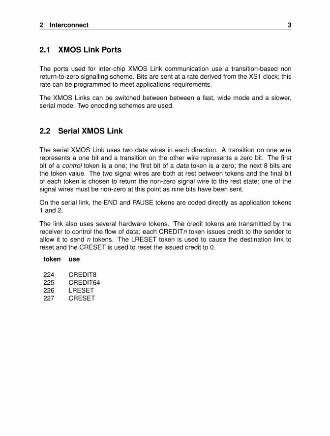
The link also uses several hardware tokens. The credit tokens are transmitted by thereceiver to control the flow of data; each CREDITn token issues credit to the sender toallow it to send n tokens. The LRESET token is used to cause the destination link toreset and the CRESET is used to reset the issued credit to 0.
token use
224 CREDIT8225 CREDIT64226 LRESET227 CRESET
4 The XMOS XS1 Architecture
2.3 Fast XMOS Link
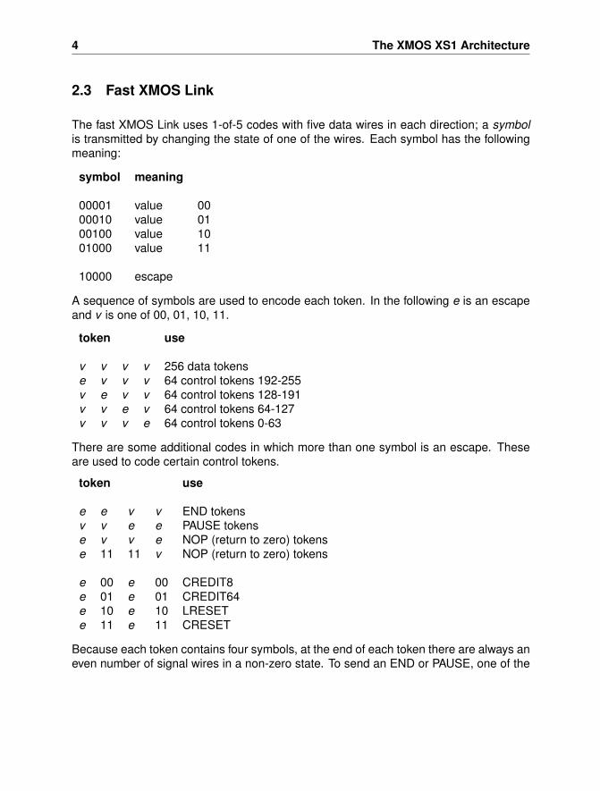
The fast XMOS Link uses 1-of-5 codes with five data wires in each direction; a symbolis transmitted by changing the state of one of the wires. Each symbol has the followingmeaning:
symbol meaning
00001 value 0000010 value 0100100 value 1001000 value 11
10000 escape
A sequence of symbols are used to encode each token. In the following e is an escapeand v is one of 00, 01, 10, 11.
token use
v v v v 256 data tokense v v v 64 control tokens 192-255v e v v 64 control tokens 128-191v v e v 64 control tokens 64-127v v v e 64 control tokens 0-63
There are some additional codes in which more than one symbol is an escape. Theseare used to code certain control tokens.
token use
e e v v END tokensv v e e PAUSE tokense v v e NOP (return to zero) tokense 11 11 v NOP (return to zero) tokens
e 00 e 00 CREDIT8e 01 e 01 CREDIT64e 10 e 10 LRESETe 11 e 11 CRESET
Because each token contains four symbols, at the end of each token there are always aneven number of signal wires in a non-zero state. To send an END or PAUSE, one of the
3 Concurrent Threads 5
END or PAUSE tokens is chosen to leave at most two signal wires in a non-zero state;this can be followed by a NOP token which is chosen to leave all of the signal wires in azero state.
The encoding of the credit and reset tokens has been chosen so that the state of thesignal wires after the token is the same as it was before the token.
3 Concurrent Threads
Each XCore has hardware support for executing a number of concurrent threads. Thisincludes:
• a set of registers for each thread.
• a thread scheduler which dynamically selects which thread to execute.
• a set of synchronisers to synchronise thread execution.
• a set of channels used for communication with other threads.
• a set of ports used for input and output.
• a set of timers to control real-time execution.
• a set of clock generators to enable synchronisation of the input-output with anexternal time domain.
Instructions are provided to support initialisation, termination, starting, synchronisingand stopping threads; also there are instructions to provide input-output and inter-threadcommunication.
The set of threads on each XCore can be used:
• to implement input-output controllers executed concurrently with applications soft-ware.
• to allow communications or input-output to progress together with processing.
• to allow latency hiding in the interconnect by allowing some threads to continuewhilst others are waiting for communication to or from remote XCores.
6 The XMOS XS1 Architecture
The instruction set includes instructions that enable the threads to communicate andperform input and output. These:
• provide event-driven communications and input-output with waiting threads auto-matically descheduled.
• support streamed, packetised or synchronised communication between threadsanywhere in a system.
• enable the processor to idle with clocks disabled when all of its threads are waitingso as to save power.
• allow the interconnect to be pipelined and input-output to be buffered.
4 The XCore Instruction Set
The main features of the instruction set used by the XCore processors are as follows.
• Short instructions are provided to allow efficient access to the stack and other dataregions allocated by compilers; these also provide efficient branching and subrou-tine calling. The short instructions have been chosen on the basis of extensiveevaluation to meet the needs of modern compilers.
• The memory is byte addressed; however all accesses must be aligned on naturalboundaries so that, for example, the addresses used in 32-bit loads and storesmust have the two least significant bits zero.
• The processor supports a number of threads each of which has its own set ofregisters. Some registers are used for specific purposes such as accessing thestack, the data region or large constants in a constant pool.
• Input and output instructions allow very fast communications between threadswithin an XCore and between XCores. They also support high speed, low-latency,input and output. They are designed to support high-level concurrent programmingtechniques.
4 The XCore Instruction Set 7
Most instructions are 16-bit. Many instructions use operands in the range 0 ... 11 asthis allows sufficient three-address instructions to be encoded using 16 bit instructions.Instruction prefixes are used to extend the range of immediate operands and to providemore inter-register operations (and inter-register operations with more operands). Theprefixes are:
• PFIX which concatenates its 10-bit immediate with the immediate operand of thenext 16-bit instruction.
• EOPR which concatenates its 11-bit operation set with the following instruction.
The prefixes are inserted automatically by compilers and assemblers.
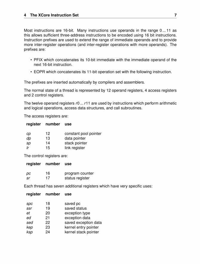
The normal state of a thread is represented by 12 operand registers, 4 access registersand 2 control registers.
The twelve operand registers r0 ... r11 are used by instructions which perform arithmeticand logical operations, access data structures, and call subroutines.
The access registers are:
register number use
cp 12 constant pool pointerdp 13 data pointersp 14 stack pointerlr 15 link register
The control registers are:
register number use
pc 16 program countersr 17 status register
Each thread has seven additional registers which have very specific uses:
register number use
spc 18 saved pcssr 19 saved statuset 20 exception typeed 21 exception datased 22 saved exception datakep 23 kernel entry pointerksp 24 kernel stack pointer
8 The XMOS XS1 Architecture
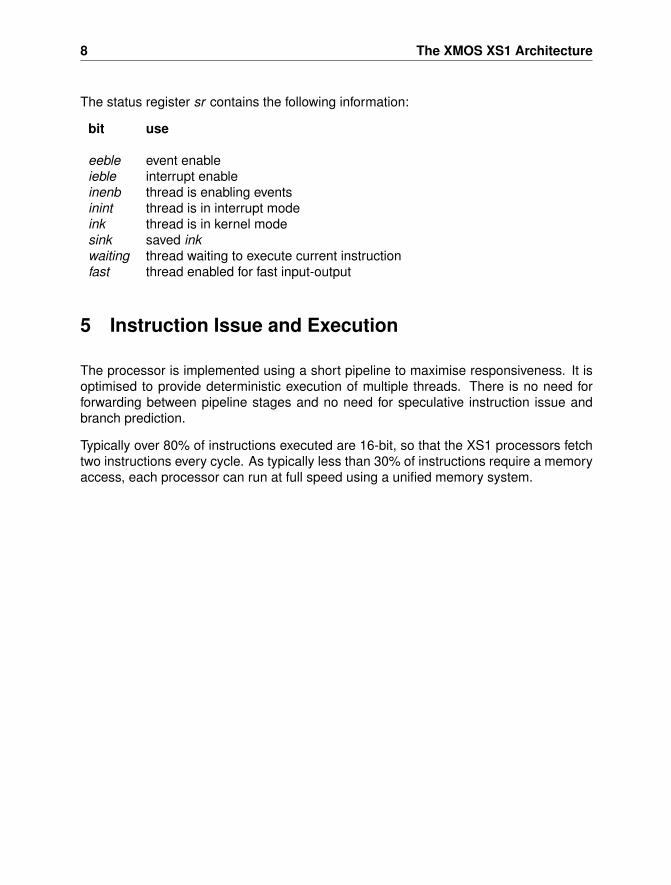
The status register sr contains the following information:
bit use
eeble event enableieble interrupt enableinenb thread is enabling eventsinint thread is in interrupt modeink thread is in kernel modesink saved inkwaiting thread waiting to execute current instructionfast thread enabled for fast input-output
5 Instruction Issue and Execution
The processor is implemented using a short pipeline to maximise responsiveness. It isoptimised to provide deterministic execution of multiple threads. There is no need forforwarding between pipeline stages and no need for speculative instruction issue andbranch prediction.
Typically over 80% of instructions executed are 16-bit, so that the XS1 processors fetchtwo instructions every cycle. As typically less than 30% of instructions require a memoryaccess, each processor can run at full speed using a unified memory system.
5 Instruction Issue and Execution 9
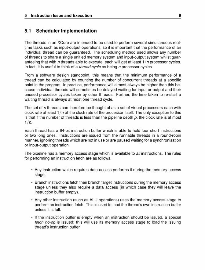
5.1 Scheduler Implementation
The threads in an XCore are intended to be used to perform several simultaneous real-time tasks such as input-output operations, so it is important that the performance of anindividual thread can be guaranteed. The scheduling method used allows any numberof threads to share a single unified memory system and input-output system whilst guar-anteeing that with n threads able to execute, each will get at least 1/n processor cycles.In fact, it is useful to think of a thread cycle as being n processor cycles.
From a software design standpoint, this means that the minimum performance of athread can be calculated by counting the number of concurrent threads at a specificpoint in the program. In practice, performance will almost always be higher than this be-cause individual threads will sometimes be delayed waiting for input or output and theirunused processor cycles taken by other threads. Further, the time taken to re-start awaiting thread is always at most one thread cycle.
The set of n threads can therefore be thought of as a set of virtual processors each withclock rate at least 1/n of the clock rate of the processor itself. The only exception to thisis that if the number of threads is less than the pipeline depth p, the clock rate is at most1/p.
Each thread has a 64-bit instruction buffer which is able to hold four short instructionsor two long ones. Instructions are issued from the runnable threads in a round-robinmanner, ignoring threads which are not in use or are paused waiting for a synchronisationor input-output operation.
The pipeline has a memory access stage which is available to all instructions. The rulesfor performing an instruction fetch are as follows.
• Any instruction which requires data-access performs it during the memory accessstage.
• Branch instructions fetch their branch target instructions during the memory accessstage unless they also require a data access (in which case they will leave theinstruction buffer empty).
• Any other instruction (such as ALU operations) uses the memory access stage toperform an instruction fetch. This is used to load the thread’s own instruction bufferunless it is full.
• If the instruction buffer is empty when an instruction should be issued, a specialfetch no-op is issued; this will use its memory access stage to load the issuingthread’s instruction buffer.
10 The XMOS XS1 Architecture
There are very few situations in which a fetch no-op is needed, and these can oftenbe avoided by simple instruction scheduling in compilers or assemblers. An obviousexample is to break long sequences of loads or stores by interspersing ALU operations.
Certain instructions cause threads to become non-runnable because, for example, aninput channel has no available data. When the data becomes available, the thread willcontinue from the point where it paused. A ready request to a thread must be receivedand an instruction issued rapidly in order to support a high rate of input and output.
To achieve this, each thread has an individual ready request signal. The thread identifieris passed to the resource (port, channel, timer etc) and used by the resource to selectthe correct ready request signal. The assertion of this will cause the thread to be re-started, normally by re-entering it into the round-robin sequence and re-issuing the inputinstruction. In most situations this latency is acceptable, although it results in a responsetime which is longer than the virtual cycle time because of the time for the re-issuedinstruction to pass through the pipeline.
To enable the virtual processor to perform one input or output per virtual cycle, a fast-mode is provided. When a thread is in fast-mode, it is not de-scheduled when an instruc-tion can not complete; instead the instruction is re-issued until it completes.
Events and interrupts are slightly different from normal input and output, because a vec-tor must also be supplied and the target instruction fetched before execution can pro-ceed. However, the same ready request system is used. The result will be to make thethread runnable but with an empty instruction buffer.
A variation on the fetch no-op is the event no-op; this is used to access the resourcewhich generated the event (or interrupt) using the thread identifier; the resource canthen supply the appropriate vector in time for it to be used for instruction fetch during theevent no-op memory access stage. This means that at most one virtual cycle is usedto process the vector, so there will be at most two virtual cycles before instruction issuefollowing an event or interrupt.
The XCore scheduler therefore allows threads to be treated as virtual processors withperformance predicted by tools. There is no possibility that the performance can bereduced below these predicted levels when virtual processors are combined.
6 Instruction Set Notation and Definitions 11
6 Instruction Set Notation and Definitions
In the following description
Bpw is the number of bytes in a wordbpw is the number of bits in a word
mem represents the memory
pc represents the program countersr represents the status registersp represents the stack pointerdp represents the data pointercp represents the constant pool pointerlr represents the link register
r0 ... r11 represent specific operand registers
x (a single small letter) represents one of r0 ... r11X (a single large letter) represents one of r0 ... r11, sp, dp, cp or lrus is a small unsigned source operand in the range 0 ... 11bitp is one of bpw , 1, 2, 3, 4, 5, 6, 7, 8, 16, 24, 32 encoded as a usu16 is a 16-bit source operand in the range 0 ... 65535u20 is a 20-bit source operand in the range 0 ... 1048575 which
Some useful functions are
zext(x , n) = x ∧ (2n − 1) zero extend
sext(x , n) = −(2n−1 ∧ x) ∨ x sign extend
6.1 Instruction Prefixes
If the most significant 10 bits of a u16 or u20 instruction operand are non-zero, a 16-bitprefix (PFIX) preceding the instruction is used to encode them. The least significant bitsare encoded within the instruction itself.
A different kind of 16-bit prefix (EOPR) is used to encode instructions with more thanthree operands, or to encode the less common instructions.
12 The XMOS XS1 Architecture
7 Data Access
The data access instructions fall into several groups. One of these provides access viathe stack pointer.
LDWSP D ← mem[sp + u16 × Bpw ] load word from stackSTWSP mem[sp + u16 × Bpw ]← S store word to stackLDAWSP D ← sp + u16 × Bpw load address of word in stack
Another is similar, but provides access via the data pointer.
LDWDP D ← mem[dp + u16 × Bpw ] load word from dataSTWDP mem[dp + u16 × Bpw ]← S store word to dataLDAWDP D ← dp + u16 × Bpw load address of word in data
Access to constants and program addresses is provided by instructions which either loadvalues directly or load them from the constant pool.
LDC D ← u16 load constantLDWCP D ← mem[cp + u16 × Bpw ] load word from constant poolLDAWCP r11← cp + u16 × Bpw ] load word address in constant poolLDWCPL r11← mem[cp + u20 × Bpw ] load word from constant pool longLDAPF r11← pc + u20 × 2 load address in program forwardLDAPB r11← pc − u20 × 2 load address in program backward
Access to data structures is provided by instructions which use any of the operand reg-isters as a base address, and combine this with a scaled offset. In the case of wordaccesses, the operand may be a small constant or another operand register, and theinstructions are as follows:
LDWI d ← mem[b + us × Bpw ] load wordSTWI mem[b + us × Bpw ]← s store wordLDAWFI d ← b + us × Bpw load address of word forwardLDAWBI d ← b − us × Bpw load address of word backward
LDW d ← mem[b + i × Bpw ] load wordSTW mem[b + i × Bpw ]← s store wordLDAWF d ← b + i × Bpw load address of word forwardLDAWB d ← b − i × Bpw load address of word backward
7 Data Access 13
In the case of access to 16-bit quantities, the base address is combined with a scaledoperand, which must be an operand register. The least significant bit of the resultingaddress must be zero. The 16-bit item is loaded and sign extended into a 32-bit value.
LD16S d ← sext(mem[b + i × 2], 16) load 16-bit signed itemST16 mem[b + i × 2]← s store 16-bit itemLDA16F d ← b + i × 2 load address of 16-bit item forwardLDA16B d ← b − i × 2 load address of 16-bit item backward
In the case of access to 8-bit quantities, the base address is combined with an unscaledoperand, which must be an operand register. The 8-bit item is loaded and zero extendedinto a 32-bit value.
LD8U d ← zext(mem[b + i ], 8) load byte unsignedST8 mem[b + i ]← s store byte
Access to part words, including bit-fields, is provided by a small set of instructions whichare used in conjunction with the shift and bitwise operations described below. Theseinstructions provide for mask generation of any length up to 32 bits, sign extension andzero-extension from any bit position, and clearing fields within words prior to insertion ofnew values.
MKMSK d ← 2s − 1 make maskMKMSKI d ← 2bitp − 1 make mask immediate
SEXT d ← sext(d , s) sign extendSEXTI d ← sext(d , bitp) sign extend immediateZEXT d ← zext(d , s) zero extendZEXTI d ← zext(d , bitp) zero extend immediate
ANDNOT d ← d ∧ ¬s and not (clear field)
The SEXTI and ZEXTI instructions can also be used in conjunction with the LD16S andLD8U instructions to load unsigned 16-bit and signed 8-bit values.
14 The XMOS XS1 Architecture
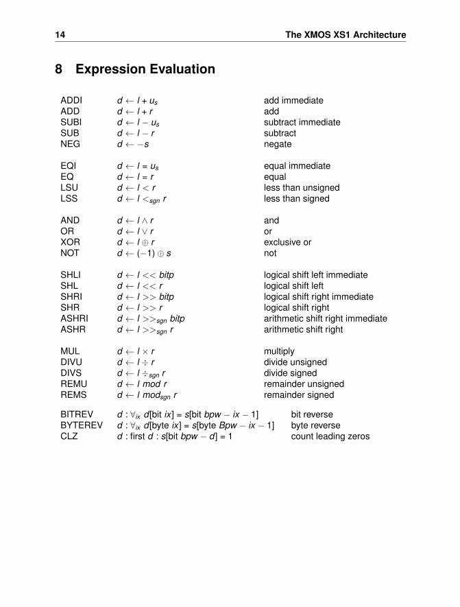
8 Expression Evaluation
ADDI d ← l + us add immediateADD d ← l + r addSUBI d ← l − us subtract immediateSUB d ← l − r subtractNEG d ← −s negate
EQI d ← l = us equal immediateEQ d ← l = r equalLSU d ← l < r less than unsignedLSS d ← l <sgn r less than signed
AND d ← l ∧ r andOR d ← l ∨ r orXOR d ← l ⊕ r exclusive orNOT d ← (−1)⊕ s not
SHLI d ← l << bitp logical shift left immediateSHL d ← l << r logical shift leftSHRI d ← l >> bitp logical shift right immediateSHR d ← l >> r logical shift rightASHRI d ← l >>sgn bitp arithmetic shift right immediateASHR d ← l >>sgn r arithmetic shift right
MUL d ← l × r multiplyDIVU d ← l ÷ r divide unsignedDIVS d ← l ÷sgn r divide signedREMU d ← l mod r remainder unsignedREMS d ← l modsgn r remainder signed
BITREV d : ∀ix d [bit ix ] = s[bit bpw − ix − 1] bit reverseBYTEREV d : ∀ix d [byte ix ] = s[byte Bpw − ix − 1] byte reverseCLZ d : first d : s[bit bpw − d ] = 1 count leading zeros
9 Branching, Jumping and Calling 15
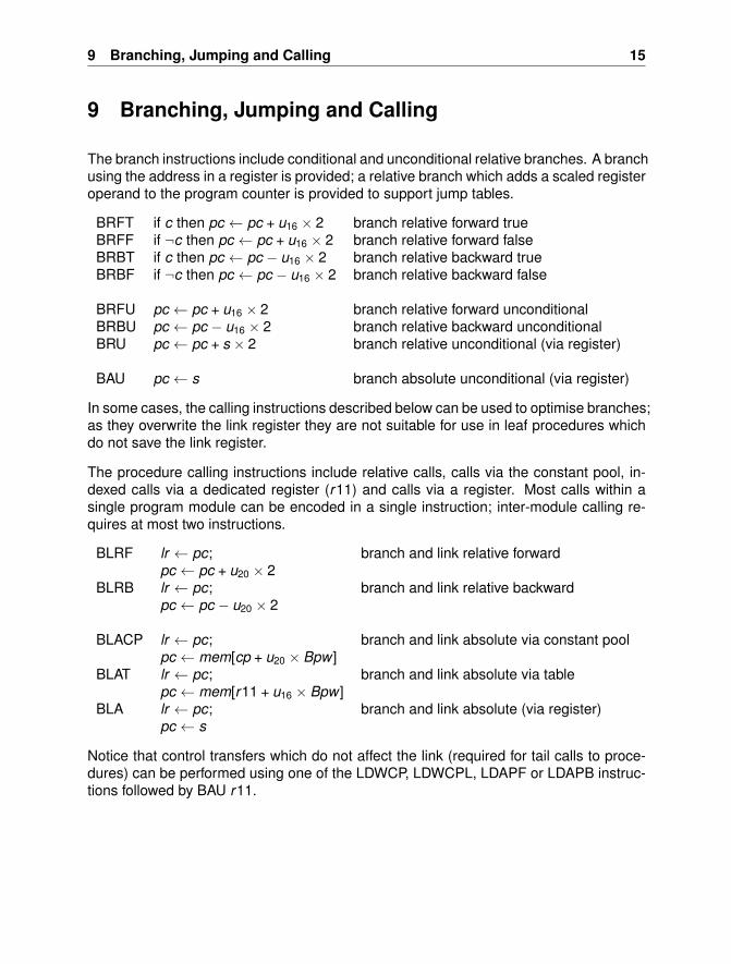
9 Branching, Jumping and Calling
The branch instructions include conditional and unconditional relative branches. A branchusing the address in a register is provided; a relative branch which adds a scaled registeroperand to the program counter is provided to support jump tables.
BRFT if c then pc ← pc + u16 × 2 branch relative forward trueBRFF if ¬c then pc ← pc + u16 × 2 branch relative forward falseBRBT if c then pc ← pc − u16 × 2 branch relative backward trueBRBF if ¬c then pc ← pc − u16 × 2 branch relative backward false
BRFU pc ← pc + u16 × 2 branch relative forward unconditionalBRBU pc ← pc − u16 × 2 branch relative backward unconditionalBRU pc ← pc + s × 2 branch relative unconditional (via register)
BAU pc ← s branch absolute unconditional (via register)
In some cases, the calling instructions described below can be used to optimise branches;as they overwrite the link register they are not suitable for use in leaf procedures whichdo not save the link register.
The procedure calling instructions include relative calls, calls via the constant pool, in-dexed calls via a dedicated register (r11) and calls via a register. Most calls within asingle program module can be encoded in a single instruction; inter-module calling re-quires at most two instructions.
BLRF lr ← pc; branch and link relative forwardpc ← pc + u20 × 2
BLRB lr ← pc; branch and link relative backwardpc ← pc − u20 × 2
BLACP lr ← pc; branch and link absolute via constant poolpc ← mem[cp + u20 × Bpw ]
BLAT lr ← pc; branch and link absolute via tablepc ← mem[r11 + u16 × Bpw ]
BLA lr ← pc; branch and link absolute (via register)pc ← s
Notice that control transfers which do not affect the link (required for tail calls to proce-dures) can be performed using one of the LDWCP, LDWCPL, LDAPF or LDAPB instruc-tions followed by BAU r11.
16 The XMOS XS1 Architecture
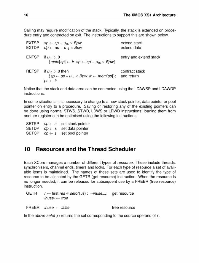
Calling may require modification of the stack. Typically, the stack is extended on proce-dure entry and contracted on exit. The instructions to support this are shown below.
EXTSP sp ← sp − u16 × Bpw extend stackEXTDP dp ← dp − u16 × Bpw extend data
ENTSP if u16 > 0 entry and extend stack{mem[sp]← lr ; sp ← sp − u16 × Bpw}
RETSP if u16 > 0 then contract stack{sp ← sp + u16 × Bpw ; lr ← mem[sp]}; and return
pc ← lr
Notice that the stack and data area can be contracted using the LDAWSP and LDAWDPinstructions.
In some situations, it is necessary to change to a new stack pointer, data pointer or poolpointer on entry to a procedure. Saving or restoring any of the existing pointers canbe done using normal STWS, STWD, LDWS or LDWD instructions; loading them fromanother register can be optimised using the following instructions.
SETSP sp ← s set stack pointerSETDP dp ← s set data pointerSETCP cp ← s set pool pointer
10 Resources and the Thread Scheduler
Each XCore manages a number of different types of resource. These include threads,synchronisers, channel ends, timers and locks. For each type of resource a set of avail-able items is maintained. The names of these sets are used to identify the type ofresource to be allocated by the GETR (get resource) instruction. When the resource isno longer needed, it can be released for subsequent use by a FREER (free resource)instruction.
GETR r ← first res ∈ setof (us) : ¬inuseres; get resourceinuser ← true
FREER inuser ← false free resource
In the above setof (r ) returns the set corresponding to the source operand of r .
10 Resources and the Thread Scheduler 17
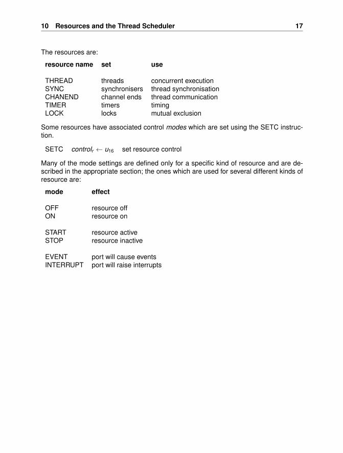
The resources are:
resource name set use
THREAD threads concurrent executionSYNC synchronisers thread synchronisationCHANEND channel ends thread communicationTIMER timers timingLOCK locks mutual exclusion
Some resources have associated control modes which are set using the SETC instruc-tion.
SETC controlr ← u16 set resource control
Many of the mode settings are defined only for a specific kind of resource and are de-scribed in the appropriate section; the ones which are used for several different kinds ofresource are:
mode effect
OFF resource offON resource on
START resource activeSTOP resource inactive
EVENT port will cause eventsINTERRUPT port will raise interrupts
18 The XMOS XS1 Architecture
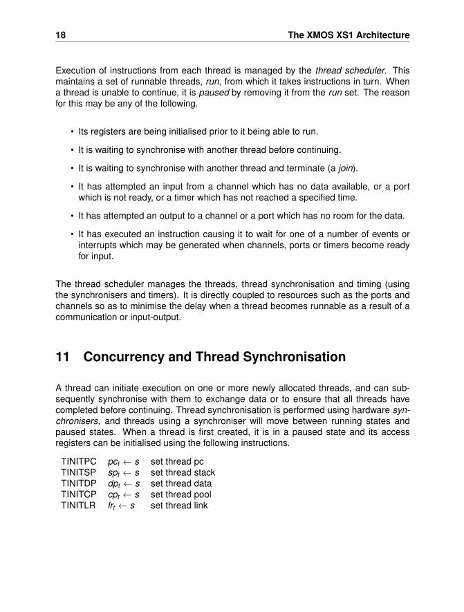
Execution of instructions from each thread is managed by the thread scheduler. Thismaintains a set of runnable threads, run, from which it takes instructions in turn. Whena thread is unable to continue, it is paused by removing it from the run set. The reasonfor this may be any of the following.
• Its registers are being initialised prior to it being able to run.
• It is waiting to synchronise with another thread before continuing.
• It is waiting to synchronise with another thread and terminate (a join).
• It has attempted an input from a channel which has no data available, or a portwhich is not ready, or a timer which has not reached a specified time.
• It has attempted an output to a channel or a port which has no room for the data.
• It has executed an instruction causing it to wait for one of a number of events orinterrupts which may be generated when channels, ports or timers become readyfor input.
The thread scheduler manages the threads, thread synchronisation and timing (usingthe synchronisers and timers). It is directly coupled to resources such as the ports andchannels so as to minimise the delay when a thread becomes runnable as a result of acommunication or input-output.
11 Concurrency and Thread Synchronisation
A thread can initiate execution on one or more newly allocated threads, and can sub-sequently synchronise with them to exchange data or to ensure that all threads havecompleted before continuing. Thread synchronisation is performed using hardware syn-chronisers, and threads using a synchroniser will move between running states andpaused states. When a thread is first created, it is in a paused state and its accessregisters can be initialised using the following instructions.
TINITPC pct ← s set thread pcTINITSP spt ← s set thread stackTINITDP dpt ← s set thread dataTINITCP cpt ← s set thread poolTINITLR lrt ← s set thread link
11 Concurrency and Thread Synchronisation 19
These instructions can only be used when the thread is paused. The TINITLR instructionis intended primarily to support debugging.
Data can be transferred between the operand registers of two threads using TSETR andTSETMR instructions, which can be used even when the destination thread is running.
TSETR dt ← s set thread operand registerTSETMR dmstr (tid) ← s set master thread operand register
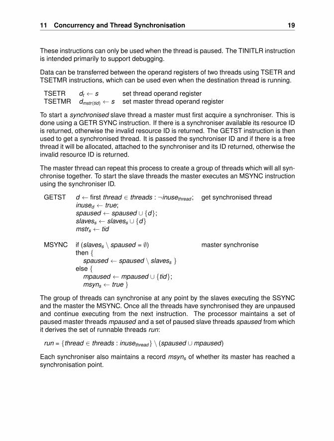
To start a synchronised slave thread a master must first acquire a synchroniser. This isdone using a GETR SYNC instruction. If there is a synchroniser available its resource IDis returned, otherwise the invalid resource ID is returned. The GETST instruction is thenused to get a synchronised thread. It is passed the synchroniser ID and if there is a freethread it will be allocated, attached to the synchroniser and its ID returned, otherwise theinvalid resource ID is returned.
The master thread can repeat this process to create a group of threads which will all syn-chronise together. To start the slave threads the master executes an MSYNC instructionusing the synchroniser ID.
GETST d ← first thread ∈ threads : ¬inusethread ; get synchronised threadinused ← true;spaused ← spaused ∪ {d};slavess ← slavess ∪ {d}mstrs ← tid
MSYNC if (slavess \ spaused = ∅) master synchronisethen {
spaused ← spaused \ slavess }else {
mpaused ← mpaused ∪ {tid};msyns ← true }
The group of threads can synchronise at any point by the slaves executing the SSYNCand the master the MSYNC. Once all the threads have synchronised they are unpausedand continue executing from the next instruction. The processor maintains a set ofpaused master threads mpaused and a set of paused slave threads spaused from whichit derives the set of runnable threads run:
run = {thread ∈ threads : inusethread} \ (spaused ∪mpaused)
Each synchroniser also maintains a record msyns of whether its master has reached asynchronisation point.
20 The XMOS XS1 Architecture
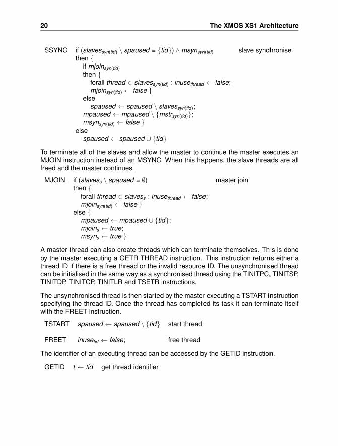
SSYNC if (slavessyn(tid) \ spaused = {tid}) ∧msynsyn(tid) slave synchronisethen {
if mjoinsyn(tid)then {
forall thread ∈ slavessyn(tid) : inusethread ← false;mjoinsyn(tid) ← false }
elsespaused ← spaused \ slavessyn(tid);
mpaused ← mpaused \ {mstrsyn(tid)};msynsyn(tid) ← false }
elsespaused ← spaused ∪ {tid}
To terminate all of the slaves and allow the master to continue the master executes anMJOIN instruction instead of an MSYNC. When this happens, the slave threads are allfreed and the master continues.
MJOIN if (slavess \ spaused = ∅) master jointhen {
forall thread ∈ slavess : inusethread ← false;mjoinsyn(tid) ← false }
else {mpaused ← mpaused ∪ {tid};mjoins ← true;msyns ← true }
A master thread can also create threads which can terminate themselves. This is doneby the master executing a GETR THREAD instruction. This instruction returns either athread ID if there is a free thread or the invalid resource ID. The unsynchronised threadcan be initialised in the same way as a synchronised thread using the TINITPC, TINITSP,TINITDP, TINITCP, TINITLR and TSETR instructions.
The unsynchronised thread is then started by the master executing a TSTART instructionspecifying the thread ID. Once the thread has completed its task it can terminate itselfwith the FREET instruction.
TSTART spaused ← spaused \ {tid} start thread
FREET inusetid ← false; free thread
The identifier of an executing thread can be accessed by the GETID instruction.
GETID t ← tid get thread identifier
12 Communication 21
12 Communication
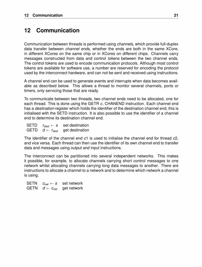
Communication between threads is performed using channels, which provide full-duplexdata transfer between channel ends, whether the ends are both in the same XCore,in different XCores on the same chip or in XCores on different chips. Channels carrymessages constructed from data and control tokens between the two channel ends.The control tokens are used to encode communication protocols. Although most controltokens are available for software use, a number are reserved for encoding the protocolused by the interconnect hardware, and can not be sent and received using instructions.
A channel end can be used to generate events and interrupts when data becomes avail-able as described below. This allows a thread to monitor several channels, ports ortimers, only servicing those that are ready.
To communicate between two threads, two channel ends need to be allocated, one foreach thread. This is done using the GETR c, CHANEND instruction. Each channel endhas a destination register which holds the identifier of the destination channel end; this isinitialised with the SETD instruction. It is also possible to use the identifier of a channelend to determine its destination channel end.
SETD rdest ← s set destinationGETD d ← rdest get destination
The identifier of the channel end c1 is used to initialise the channel end for thread c2,and vice versa. Each thread can then use the identifier of its own channel end to transferdata and messages using output and input instructions.
The interconnect can be partitioned into several independent networks. This makesit possible, for example, to allocate channels carrying short control messages to onenetwork whilst allocating channels carrying long data messages to another. There areinstructions to allocate a channel to a network and to determine which network a channelis using.
SETN cnet ← s set networkGETN d ← cnet get network
22 The XMOS XS1 Architecture
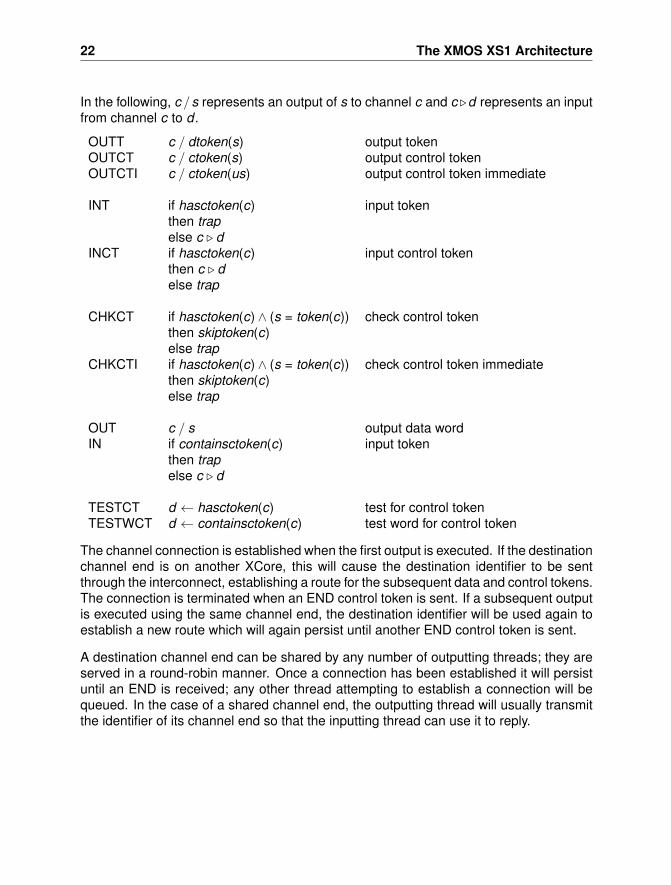
In the following, c /s represents an output of s to channel c and c .d represents an inputfrom channel c to d .
OUTT c / dtoken(s) output tokenOUTCT c / ctoken(s) output control tokenOUTCTI c / ctoken(us) output control token immediate
INT if hasctoken(c) input tokenthen trapelse c . d
INCT if hasctoken(c) input control tokenthen c . delse trap
CHKCT if hasctoken(c) ∧ (s = token(c)) check control tokenthen skiptoken(c)else trap
CHKCTI if hasctoken(c) ∧ (s = token(c)) check control token immediatethen skiptoken(c)else trap
OUT c / s output data wordIN if containsctoken(c) input token
then trapelse c . d
TESTCT d ← hasctoken(c) test for control tokenTESTWCT d ← containsctoken(c) test word for control token
The channel connection is established when the first output is executed. If the destinationchannel end is on another XCore, this will cause the destination identifier to be sentthrough the interconnect, establishing a route for the subsequent data and control tokens.The connection is terminated when an END control token is sent. If a subsequent outputis executed using the same channel end, the destination identifier will be used again toestablish a new route which will again persist until another END control token is sent.
A destination channel end can be shared by any number of outputting threads; they areserved in a round-robin manner. Once a connection has been established it will persistuntil an END is received; any other thread attempting to establish a connection will bequeued. In the case of a shared channel end, the outputting thread will usually transmitthe identifier of its channel end so that the inputting thread can use it to reply.
12 Communication 23
The OUT and IN instructions are used to transmit words of data through the channel;to transmit bytes of data the OUTT and INT instructions are used. Control tokens aresent using OUTCT or OUTCTI and received using INCT. To support efficient runtimechecks that the type, length or structure of output data matches that expected by theinputer, CHKCT and CHKCTI instructions are provided. The CHKCT instruction inputsand discards a token provided that the input token matches its operand; otherwise ittraps. The normal IN and INT instructions trap if they encounter a control token. To inputa control token INCT is used; this traps if it encounters a data token.
The END control token is one of the 12 tokens which can be sent using OUTCTI andchecked using CHKCTI. By following each message output with an OUTCTI c, END andeach input with a CHKCTI c, END it is possible to check that the size of the messageis the same as the size of the message expected by the inputting thread. To performsynchronised communication, the output message should be followed with (OUTCTI c,END; CHKCTI c, END) and the input with (CHKCTI c, END; OUTCTI c, END).
Another control token is PAUSE. Like END, this causes the route through the interconnectto be disconnected. However the PAUSE token is not delivered to the receiving thread.It is used by the outputting thread to break up long messages or streams, allowing theinterconnect to be shared efficiently. The remaining control tokens are used for runtimechecking and for signalling the type of message being received; they have no effect onthe interconnect. Note that in addition to END and PAUSE, ten of these can be efficientlyhandled using OUTCTI and CHKCTI.
A control token takes up a single byte of storage in the channel. On the receiving end thesoftware can test whether the next token is a control token using the TESTCT instruction,which waits until at least one token is available. It is also possible to test whether the nextword contains a control token using the TESTWCT instruction. This waits until a wholeword of data tokens has been received (in which case it returns 0) or until a control tokenhas been received (in which case it returns the byte position after the position of the bytecontaining the control token).
Channel ends have a buffer able to hold sufficient tokens to allow at least one word to bebuffered. If an output instruction is executed when the channel is too full to take the datathen the thread which executed the instruction is paused. It is restarted when there isenough room in the channel for the instruction to successfully complete. Likewise, whenan input instruction is executed and there is not enough data available then the thread ispaused and will be restarted when enough data becomes available.
Note that when sending long messages to a shared channel, the sender should send ashort request and then wait for a reply before proceeding as this will minimise intercon-nect congestion caused by delays in accepting the message.
24 The XMOS XS1 Architecture
When a channel end c is no longer required, it can be freed using a FREER c instruction.Otherwise it can be used for another message.
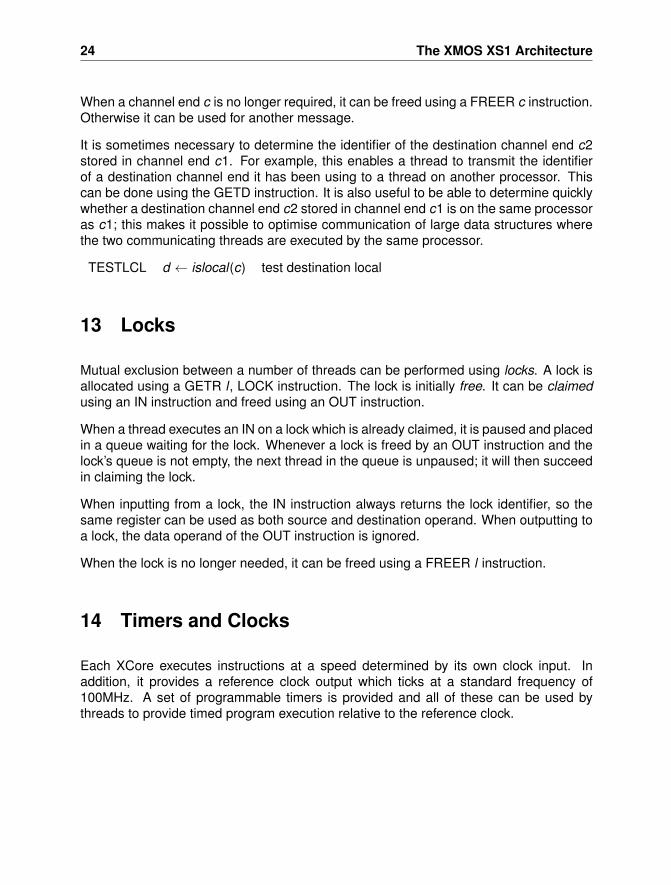
It is sometimes necessary to determine the identifier of the destination channel end c2stored in channel end c1. For example, this enables a thread to transmit the identifierof a destination channel end it has been using to a thread on another processor. Thiscan be done using the GETD instruction. It is also useful to be able to determine quicklywhether a destination channel end c2 stored in channel end c1 is on the same processoras c1; this makes it possible to optimise communication of large data structures wherethe two communicating threads are executed by the same processor.
TESTLCL d ← islocal(c) test destination local
13 Locks
Mutual exclusion between a number of threads can be performed using locks. A lock isallocated using a GETR l , LOCK instruction. The lock is initially free. It can be claimedusing an IN instruction and freed using an OUT instruction.
When a thread executes an IN on a lock which is already claimed, it is paused and placedin a queue waiting for the lock. Whenever a lock is freed by an OUT instruction and thelock’s queue is not empty, the next thread in the queue is unpaused; it will then succeedin claiming the lock.
When inputting from a lock, the IN instruction always returns the lock identifier, so thesame register can be used as both source and destination operand. When outputting toa lock, the data operand of the OUT instruction is ignored.
When the lock is no longer needed, it can be freed using a FREER l instruction.
14 Timers and Clocks
Each XCore executes instructions at a speed determined by its own clock input. Inaddition, it provides a reference clock output which ticks at a standard frequency of100MHz. A set of programmable timers is provided and all of these can be used bythreads to provide timed program execution relative to the reference clock.
14 Timers and Clocks 25
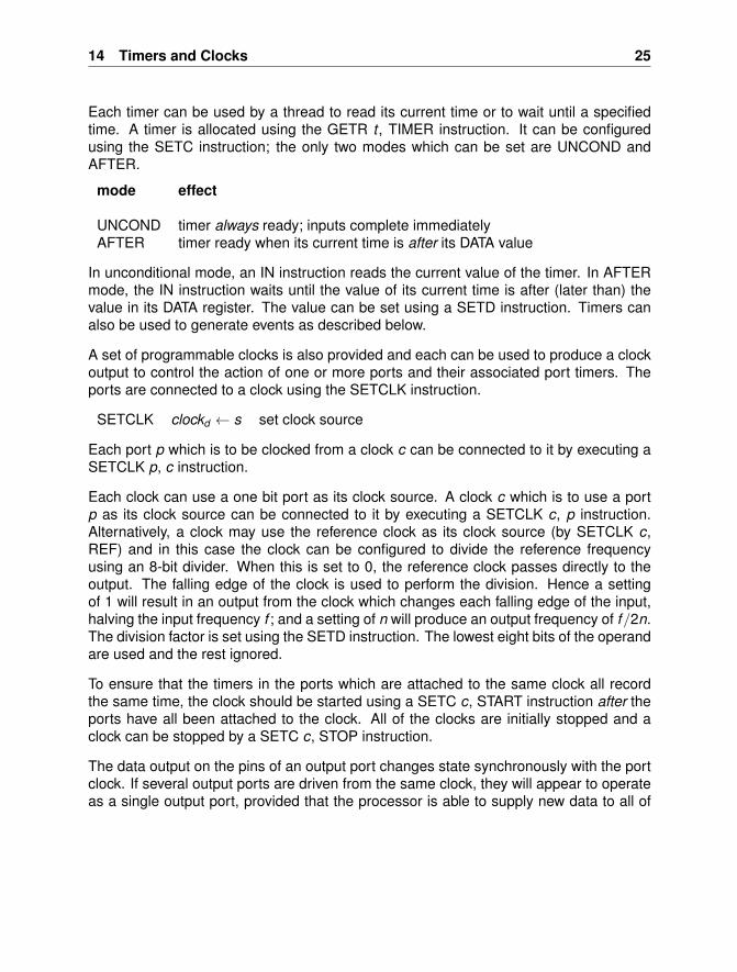
Each timer can be used by a thread to read its current time or to wait until a specifiedtime. A timer is allocated using the GETR t , TIMER instruction. It can be configuredusing the SETC instruction; the only two modes which can be set are UNCOND andAFTER.
mode effect
UNCOND timer always ready; inputs complete immediatelyAFTER timer ready when its current time is after its DATA value
In unconditional mode, an IN instruction reads the current value of the timer. In AFTERmode, the IN instruction waits until the value of its current time is after (later than) thevalue in its DATA register. The value can be set using a SETD instruction. Timers canalso be used to generate events as described below.
A set of programmable clocks is also provided and each can be used to produce a clockoutput to control the action of one or more ports and their associated port timers. Theports are connected to a clock using the SETCLK instruction.
SETCLK clockd ← s set clock source
Each port p which is to be clocked from a clock c can be connected to it by executing aSETCLK p, c instruction.
Each clock can use a one bit port as its clock source. A clock c which is to use a portp as its clock source can be connected to it by executing a SETCLK c, p instruction.Alternatively, a clock may use the reference clock as its clock source (by SETCLK c,REF) and in this case the clock can be configured to divide the reference frequencyusing an 8-bit divider. When this is set to 0, the reference clock passes directly to theoutput. The falling edge of the clock is used to perform the division. Hence a settingof 1 will result in an output from the clock which changes each falling edge of the input,halving the input frequency f ; and a setting of n will produce an output frequency of f/2n.The division factor is set using the SETD instruction. The lowest eight bits of the operandare used and the rest ignored.
To ensure that the timers in the ports which are attached to the same clock all recordthe same time, the clock should be started using a SETC c, START instruction after theports have all been attached to the clock. All of the clocks are initially stopped and aclock can be stopped by a SETC c, STOP instruction.
The data output on the pins of an output port changes state synchronously with the portclock. If several output ports are driven from the same clock, they will appear to operateas a single output port, provided that the processor is able to supply new data to all of
26 The XMOS XS1 Architecture
them during each clock cycle. Similarly, the data input by an input port from the port pinsis sampled synchronously with the port clock. If several input ports are driven from thesame clock they will appear to operate as a single input port provided that the processoris able to take the data from all of them during each clock cycle.
The use of clocked ports therefore decouples the internal timing of input and outputprogram execution from the operation of synchronous input and output interfaces.
15 Ports, Input and Output
Ports are interfaces to physical pins. A port can be used for input or output. It can use thereference clock as its port clock or it can use one of the programmable clocks. Transfersto and from the pins can be synchronised with the execution of input and output instruc-tions, or the port can be configured to buffer the transfers and to convert automaticallybetween serial and parallel form. Ports can also be timed to provide precise timing ofvalues appearing on output pins or taken from input pins. When inputting, a conditioncan be used to delay the input until the data in the port meets the condition. When thecondition is met the captured data is time stamped with the time at which it was captured.
The port clock input is initially the reference clock. It can be changed using the SETCLKinstruction with a clock ID as the clock operand. This port clock drives the port timer andcan also be used to determine when data is taken from or presented to the pins.
A port can be used to generate events and interrupts when input data becomes availableas described below. This allows a thread to monitor several ports, channels or timers,only servicing those that are ready.
15.1 Input and Output
Each port has a transfer register. The input and output instructions used for channels, INand OUT, can also be used to transfer data to and from a port transfer register. The INinstruction zero-extends the contents of a port transfer register and transfers the resultto an operand register. The OUT instruction transfers the least significant bits from anoperand register to a port transfer register.
15 Ports, Input and Output 27
Two further instructions, INSHR and OUTSHR, optimise the transfer of data. The INSHRinstruction shifts the contents of its destination register right, filling the left-most bits withthe data transferred from the port. The OUTSHR instruction transfers the least significantbits of data from its source register to the port and shifts the contents of the sourceregister right.
OUTSHR p / s[bits 0 for trwidth(p)]; output to ports ← s >> trwidth(p) and shift
INSHR s ← s >> trwidth(p); shift andp . s[bits (bpw − trwidth(p)) for trwidth(p)] input from port
The transfer register is accessed by the processor; it is also accessed by the port whendata is moved to or from the pins. When the processor writes data into the transferregister it fills the transfer register; when the processor takes data from the transferregister it empties the transfer register.
15.2 Port Configuration
A port is initially OFF with its pins in a high impedance state. Before it is used, it mustbe configured to determine the way it interacts with its pins, and set ON, which alsohas the effect of starting the port. The port can subsequently be stopped and startedusing SETC p, STOP and SETC p, START; between these the port configuration can bechanged.
The port configuration is done using the SETC instruction which is used to define severalindependent settings of the port. Each of these has a default mode and need onlybe configured if a different mode is needed. The effect of the SETC mode settings isdescribed below. The bold entry in each setting is the default mode.
28 The XMOS XS1 Architecture
mode effect
NOREADY no ready signals are usedHANDSHAKEN both ready input and ready output signals are usedSTROBED one ready signal is used (output on master, input on slave)
SYNCHRONISED processor synchronises with pinsBUFFERED port buffers data between pins and processor
SLAVE port acts as a slaveMASTER port acts as a master
NOSDELAY input sample not delayedSDELAY input sample delayed half a clock period
DATAPORT port acts as normalCLOCKPORT the port outputs its source clockREADYPORT the port outputs a ready signal
DRIVE pins are driven both high and lowPULLDOWN pins pull down for 0 bits, are high impedance otherwisePULLUP pins pull up for 1 bits, but are high impedance otherwise
NOINVERT data is not invertedINVERT data is inverted
The DRIVE, PULLDOWN and PULLUP modes determine the way the pins are drivenwhen outputting, and the way they are pulled when inputting. The CLOCKPORT, READY-PORT and INVERT settings can only be used with 1-bit ports.
Initially, the port is ready for input. Subsequently, it may change to output data when anoutput instruction is executed; after outputting it may change back to inputting when aninput instruction is executed.
It is sometimes useful to read the data on the pins when the port is outputting; this canbe done using the PEEK instruction:
PEEK d ← pins(p) read port pins
15 Ports, Input and Output 29
15.3 Configuring Ready and Clock Signals
A port can be configured to use ready input and ready output signals.
A port’s ready input signal is input by an associated one-bit port. This association ismade using the SETRDY instruction.
SETRDY readyp ← s set source of port ready input
A port’s ready output signal is output by another associated one-bit port. A one-bit portr which is to be used as a ready output must first be configured in READYPORT modeby SETC r , READYPORT. This ready port r can then be associated with a port p bySETRDY r , p.
A one-bit port can be used to output a clock signal by setting it into CLOCKPORT mode;its clock source is set using the SETCLK instruction.
When a 1-bit port is configured to be in CLOCKPORT or READYPORT mode, the drivemode and invert mode are configurable as normal.
15.4 NOREADY mode
If the port is in NOREADY mode, no ready signals are used and data is moved to andfrom the pins either asynchronously (at times determined by the execution of input andoutput instructions) or synchronously with the port clock, irrespective of whether the portis in MASTER or SLAVE mode.
At most one input or output is performed per cycle of the port clock.
15.5 HANDSHAKEN mode
In HANDSHAKEN mode, ready signals are used to control when data is moved to orfrom a port’s pins.
A port in MASTER HANDSHAKEN mode initiates an output cycle by moving data to thepins and asserting the ready output (request); it then waits for the ready input (reply) tobe asserted. It initiates an input cycle by asserting the ready output (request) and waitingfor the ready input (reply) to be asserted along with the data; it then takes the data.
A port in SLAVE HANDSHAKEN mode waits for the ready input (request) to be asserted.
30 The XMOS XS1 Architecture
It performs an input cycle by taking the data and asserting the ready output (reply); itperforms an output cycle by moving data to the pins and asserting the ready output(reply).
The ready signals accompany the data in each cycle of the port clock. The falling edgeof the port clock initiates the set up of data or a change of port direction; the port timeralso advances on this edge. On output, the data and the ready output will be valid onthe rising edge of the port clock. On input, data and the ready input will be sampled onthe rising edge of the port clock unless the port is configured as SDELAY, in which casethey are sampled on the falling edge.
15.6 STROBED mode
In STROBED mode only one ready signal is used and the port can be in MASTER orSLAVE mode. A MASTER port asserts its ready output and the slave has to keep up; aSLAVE port has to keep up with the ready input.
Note that a port in NOREADY mode behaves in the same way as a port in STROBEDmode which is always ready.
15.7 The Port Timer
A port has a timer which can be used to cause the transfer of data to or from the pins totake place at a specified time. The time at which the transfer is to be performed is setusing the SETPT (set port time) instruction. Timed ports are often used together withtimestamping as this allows precise control of response times.
SETPT porttimep ← s set port timeCLRPT clearporttime(p) clear port timeGETTS d ← timestampp get port timestamp
The CLRPT instruction can be used to cancel a timed transfer.
The timestamp which is set when a port becomes ready for input can be read using theGETTS instruction.
15 Ports, Input and Output 31
15.8 Conditions
A port has an associated condition which can be used to prevent the processor fromtaking input from the port when the condition is not met. The conditions are set usingthe SETC instruction. The value used for comparison in some of the conditions is heldin the port data register, which can be set using the SETD instruction.
mode port ready condition
NONE no conditionEQ value on pins equal to port data register valueNEQ value on pins not equal to port data register value
The simplest condition is NONE. The other conditions all involve comparing the valuefrom the pins with the value in the port data register.
When the condition is met a timestamp is set and the port becomes ready for input.
When a port is used to generate an event, the data which satisfied the condition is heldin the transfer register and the timestamp is set. The value returned by a subsequentinput on the port is guaranteed to meet the condition and to correspond to the timestampeven if the value on the port has changed.
15.9 Synchronised Transfers
A port in SYNCHRONISED mode ensures that the signalling operation of the port pinsis synchronised with the processor instruction execution.
When a SETPT instruction is used, the movement of data between the pins and thetransfer register takes place when the current value of the port timer matches the timespecified with the SETPT instruction.
If the port is used for output and the transfer register is full, the SETPT instruction willpause until the transfer register is empty. This ensures that the port time is not changeduntil the pending output has completed.
If a condition other than NONE is used the port will only be ready for input when thedata in the transfer register matches the condition. If an input instruction is executed andthe specified condition is not met, the thread executing the input will be paused until thecondition is met; the thread then resumes and completes the input. The value of the porttimer corresponding to the data in the transfer register when a port condition is met isrecorded in the port timestamp register. The timestamp register is read at any time usingthe GETTS instruction.
32 The XMOS XS1 Architecture
15.10 Buffered Transfers
A port in BUFFERED mode buffers the transfer of data between the processor and thepins through the use of a shift register, which is situated between the transfer registerand the pins. A buffered port can be used to convert between parallel and serial formusing its shift register. The number of bits in the transfer register and the shift registerdetermines the width of the transfers (the transfer width) between the processor andthe port; this is a multiple of the port width (the number of pins) and can be set by theSETTW instruction.
SETTW widthp ← s set port transfer width
For a 32-bit wordlength, the transfer width is normally 32, 8, 4 or 1 bit.
Note that in contrast to a synchronised transfer, where the transfer width and the portwidth are equal, the transfer width of a buffered transfer can differ from the port width.
On input, the shift register is full when n values have been taken from the p pins, wheren × p is the transfer width; it will then be emptied to the transfer register ready for aninput instruction. On output the shift register is filled from the transfer register and will beempty when n values have been moved to the p pins, where n × p is the transfer width.
The port operates as follows:
• HANDSHAKEN: A handshaken transfer only shifts data from the pins to the shiftregister on input when the shift register is not full; on output it only shifts data fromthe shift register to the pins when the shift register is not empty. On input, the shiftregister will become full if the processor does not input data to empty the transferregister; when the processor inputs the data, the transfer register is filled from theshift register and the shift register will start to be re-filled from the pins. On output,the shift register will become empty if the processor does fill the transfer register;when the processor outputs data to fill the transfer register, the shift register will befilled from the transfer register and the shift register will then start to be emptied tothe pins.
• STROBED SLAVE Input: Data is shifted into the shift register from the pins when-ever the ready input is asserted. Provided that the transfer register is empty, whenthe shift register is full the transfer register is filled from the shift register. When theprocessor executes an input instruction to take data from the transfer register, thetransfer register is emptied.
If the processor does not take the data from the transfer register by the time theshift register is next full, data will continue to be shifted into the shift register and
15 Ports, Input and Output 33
only the most recent values will be kept; as soon as an input instruction emptiesthe transfer register the transfer register will be filled from the shift register.
• STROBED SLAVE Output: Data is shifted out to the pins whenever the readyinput is asserted. Provided that the transfer register is full, when the shift registeris empty, it is filled from the transfer register. When the processor executes anoutput instruction it fills the transfer register.
If the processor has not filled the transfer register by the time the shift register isnext empty, the data is held on the pins. As soon as the processor executes andoutput instruction it fills the transfer register; the shift register is then filled from thetransfer register and the it will start to be emptied to the pins.
• STROBED MASTER: The transfer operates in the same way as a handshakentransfer in which the ready input is always asserted.
The SETPT instruction can be used to delay the movement of data between the shiftregister and the transfer register until the current value of the port timer matches thetime specified.
Note that this can be used to provide synchronisation with a stream of data in a BUFFEREDport in NOREADY mode, because exactly one item will be shifted to or from the pins ineach clock cycle.
If the port is outputting and the transfer register is full the SETPT instruction will pauseuntil it is empty. This ensures that the port time is not changed until the pending outputhas completed.
The port condition can be used to locate the first item of data on the pins that matchesa condition. If the condition is different from NONE, data will be held in the shift registeruntil the data meets the condition; the data is then moved to the transfer register, thetimestamp is set and the port changes the condition to NONE so that data can continueto fill the shift register in the normal way. Only the top port-width bits of the shift registerare used for comparison when the condition is checked.
34 The XMOS XS1 Architecture
15.11 Partial Transfers
Buffered transfers permit data of less than the transfer width to be moved between theshift register and the transfer register. The length of the items in a buffered transfercan be set by a SETPSC instruction, which sets the port shift register count. On input,this will cause the shift register contents to be moved to the transfer register when thespecified amount of data has been shifted in; on output it will cause only the specifiedamount of data to be shifted out before the shift register is ready to be re-loaded. This isuseful for handling the first and last items in a long transfer.
SETPSC shiftcountp ← s set port shift register count
A buffered input can be terminated by executing an ENDIN instruction which returns thenumber of items buffered in the port (which will include the shift register and transfer reg-ister contents) and also sets the port shift register count to the amount of data remainingin the shift register, enabling a following input to complete.
ENDIN d ← buffercountp end input
To optimise the transfer of partwords two further instructions are provided:
OUTPW shiftcountp ← bitp; output part wordp / s
INPW shiftcountp ← bitp; input part wordp . d
These encode their immediate operand in the same way as the shift instructions.
15.12 Changing Direction
A SYNCHRONISED port can change from input to output, or from output to input. Thedirection changes at the start of the next setup period. For a transfer initiated by aSETPT instruction, the direction will be input unless an output is executed before thetime specified by the SETPT instruction.
A BUFFERED port can change direction only after it has completed a transfer. This isdone by stopping and re-starting the port using SETC p, STOP and SETC p, STARTinstructions.
16 Events, Interrupts and Exceptions 35
16 Events, Interrupts and Exceptions
Events and interrupts allow timers, ports and channel ends to automatically transfer con-trol to a pre-defined event handler. The ability of a thread to accept events or interruptsis controlled by information held in the thread status register (sr ), and may be explicitlycontrolled using SETSR and CLRSR instructions with appropriate operands.
SETSR sr ← sr ∨ u6 set thread stateCLRSR sr ← sr ∧ ¬u6 clear thread stateGETSR r11← sr ∧ u6 get thread state
The operand of these instructions should be one (or more) of
EEBLE enable eventsIEBLE enable interruptsINENB determine if thread is enabling eventsININT determine if thread is in interrupt modeINK determine if thread is in kernel modeSINK determine if thread was in kernel modeWAITING determine if thread is waiting to execute the current instructionFAST determine if thread is in fast mode
A thread normally enables one or more events and then waits for one of them to occur.Hence, on an event all the thread’s state is valid, allowing the thread to respond rapidlyto the event. The thread can perform input and output operations using the port, channelor timer which gave rise to an event whilst leaving some or all of the event informationunchanged. This allows the thread to complete handling an event and immediately waitfor another similar event.
Timers, ports and channel ends all support events, the only difference being the readyconditions used to trigger the event. The program location of the event handler must beset prior to enabling the event using the SETV instruction. The SETEV instruction canbe used to set an environment for the event handler; this will often be a stack addresscontaining data used by the handler. Timers and ports have conditions which determinewhen they will generate an event; these are set using the SETC and SETD instructions.Channel ends are considered ready as soon as they contain enough data.
Event generation by a specific port, timer or channel can be enabled using an event en-able unconditional (EEU) instruction and disabled using an event disable unconditional(EDU) instruction. The event enable true (EET) instruction enables the event if its con-dition operand is true and disables it otherwise; conversely the event enable false (EEF)instruction enables the event if its condition operand is false, and disables it otherwise.
36 The XMOS XS1 Architecture
These instructions are used to optimise the implementation of guarded inputs.
SETV vectorr ← s set event vectorSETEV envectorr ← s set event environment vector
SETD datar ← s set resource dataGETD d ← datar get resource dataSETC condr ← s set event condition
EET enbr ← c; threadr ← tid event enable trueEEF enbr ← ¬c; threadr ← tid event enable falseEDU enbr ← false; threadr ← tid event disableEEU enbr ← true; threadr ← tid event enable
Having enabled events on one or more resources, a thread can use a WAITEU, WAITETor WAITEF instruction to wait for at least one event. The WAITEU instruction waitsunconditionally; the WAITET instruction waits only if its condition operand is true, andthe WAITEF waits only if its condition operand is false.
WAITET if c then eebletid ← true event wait if trueWAITEF if ¬ c then eebletid ← true event wait if falseWAITEU eebletid ← true event wait
This may result in an event taking place immediately with control being transferred tothe event handler specified by the corresponding event vector with events disabled byclearing the thread’s eeble flag. Alternatively the thread may be paused until an eventtakes place with the eeble flag enabled; in this case the eeble flag will be cleared whenthe event takes place, and the thread resumes execution.
event ed ← evres;pc ← vres;sr [bit inenb]← false;sr [bit eeble]← false;sr [bit waiting]← false
Note that the environment vector is transferred to the event data register, from where itcan be accessed by the GETED instruction. This allows it to be used to access dataassociated with the event, or simply to enable several events to share the same eventvector.
To optimise the responsiveness of a thread to high priority resources the SETSR EEBLEinstruction can be used to enable events before starting to enable the ports, channelsand timers. This may cause an event to be handled immediately, or as soon as it is
16 Events, Interrupts and Exceptions 37
enabled. An enabling sequence of this kind can be followed either by a WAITEU instruc-tion to wait for one of the events, or it can simply be followed by a CLRSR EEBLE tocontinue execution when no event takes place. The WAITET and WAITEF instructionscan also be used in conjunction with a CLRSR EEBLE to conditionally wait or continuedepending on a guarding condition. The WAITET and WAITEF instructions can also beused to optimise the common case of repeatedly handling events from multiple sourcesuntil a terminating condition occurs.
All of the events which have been enabled by a thread can be disabled using a singleCLRE instruction. This disables event generation in all of the ports, channels or timerswhich have had events enabled by the thread. The CLRE instruction also clears thethread’s eeble flag.
CLRE eebletid ← false; disable all eventsinenbtid ← false; for threadforall res
if (threadres = tid ∧ eventres) then enbres ← false
Where enabling sequences include calls to input subroutines, the SETSR INENB instruc-tion can be used to record that the processor is in an enabling sequence; the subroutinebody can use GETSR INENB to branch to its enabling code (instead of its normal in-putting code). INENB is cleared whenever an event occurs, or by the CLRE instruction.
In contrast to events, interrupts can occur at any point during program execution, andso the current pc and sr (and potentially also some or all of the other registers) mustbe saved prior to execution of the interrupt handler. This is done using the spc and ssrregisters. On an interrupt generated by resource r the following occurs automatically:
int spc ← pc;ssr ← sr ;pc ← vres;sed ← ed ;ed ← evressr [bit inint ]← truesr [bit ink ]← true;sr [bit eeble]← false;sr [bit ieble]← falsesr [bit waiting]← false
38 The XMOS XS1 Architecture
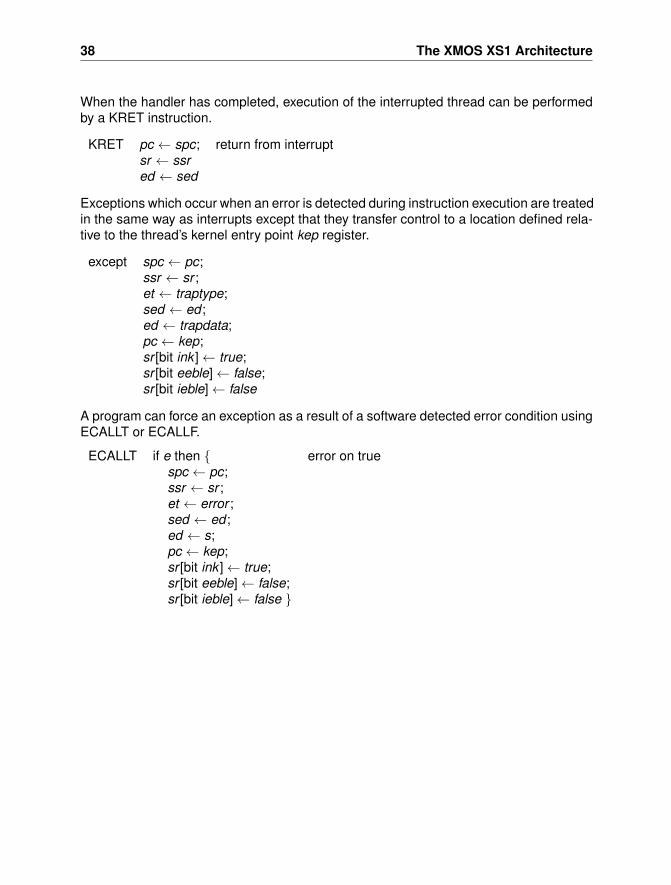
When the handler has completed, execution of the interrupted thread can be performedby a KRET instruction.
KRET pc ← spc; return from interruptsr ← ssred ← sed
Exceptions which occur when an error is detected during instruction execution are treatedin the same way as interrupts except that they transfer control to a location defined rela-tive to the thread’s kernel entry point kep register.
except spc ← pc;ssr ← sr ;et ← traptype;sed ← ed ;ed ← trapdata;pc ← kep;sr [bit ink ]← true;sr [bit eeble]← false;sr [bit ieble]← false
A program can force an exception as a result of a software detected error condition usingECALLT or ECALLF.
ECALLT if e then { error on truespc ← pc;ssr ← sr ;et ← error ;sed ← ed ;ed ← s;pc ← kep;sr [bit ink ]← true;sr [bit eeble]← false;sr [bit ieble]← false }
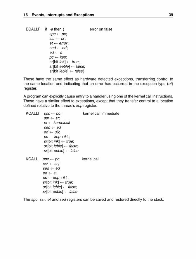
16 Events, Interrupts and Exceptions 39
ECALLF if ¬e then { error on falsespc ← pc;ssr ← sr ;et ← error ;sed ← ed ;ed ← spc ← kep;sr [bit ink ]← true;sr [bit eeble]← false;sr [bit ieble]← false}
These have the same effect as hardware detected exceptions, transferring control tothe same location and indicating that an error has occurred in the exception type (et)register.
A program can explicitly cause entry to a handler using one of the kernel call instructions.These have a similar effect to exceptions, except that they transfer control to a locationdefined relative to the thread’s kep register.
KCALLI spc ← pc; kernel call immediatessr ← sr ;et ← kernelcallsed ← eded ← u6;pc ← kep + 64;sr [bit ink ]← true;sr [bit ieble]← false;sr [bit eeble]← false
KCALL spc ← pc; kernel callssr ← sr ;sed ← eded ← s;pc ← kep + 64;sr [bit ink ]← true;sr [bit ieble]← false;sr [bit eeble]← false
The spc, ssr , et and sed registers can be saved and restored directly to the stack.
40 The XMOS XS1 Architecture
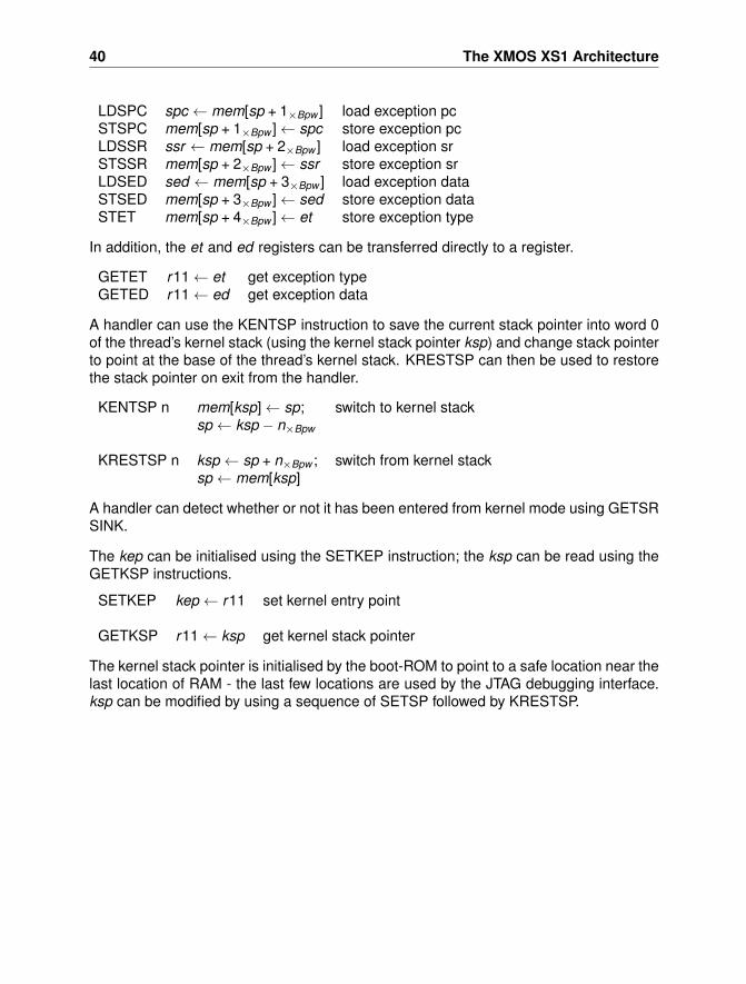
LDSPC spc ← mem[sp + 1×Bpw ] load exception pcSTSPC mem[sp + 1×Bpw ]← spc store exception pcLDSSR ssr ← mem[sp + 2×Bpw ] load exception srSTSSR mem[sp + 2×Bpw ]← ssr store exception srLDSED sed ← mem[sp + 3×Bpw ] load exception dataSTSED mem[sp + 3×Bpw ]← sed store exception dataSTET mem[sp + 4×Bpw ]← et store exception type
In addition, the et and ed registers can be transferred directly to a register.
GETET r11← et get exception typeGETED r11← ed get exception data
A handler can use the KENTSP instruction to save the current stack pointer into word 0of the thread’s kernel stack (using the kernel stack pointer ksp) and change stack pointerto point at the base of the thread’s kernel stack. KRESTSP can then be used to restorethe stack pointer on exit from the handler.
KENTSP n mem[ksp]← sp; switch to kernel stacksp ← ksp − n×Bpw
KRESTSP n ksp ← sp + n×Bpw ; switch from kernel stacksp ← mem[ksp]
A handler can detect whether or not it has been entered from kernel mode using GETSRSINK.
The kep can be initialised using the SETKEP instruction; the ksp can be read using theGETKSP instructions.
SETKEP kep ← r11 set kernel entry point
GETKSP r11← ksp get kernel stack pointer
The kernel stack pointer is initialised by the boot-ROM to point to a safe location near thelast location of RAM - the last few locations are used by the JTAG debugging interface.ksp can be modified by using a sequence of SETSP followed by KRESTSP.
17 Initialisation and Debugging 41
17 Initialisation and Debugging
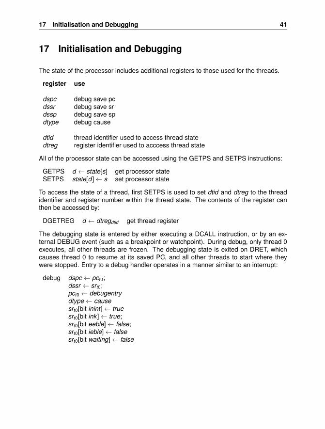
The state of the processor includes additional registers to those used for the threads.
register use
dspc debug save pcdssr debug save srdssp debug save spdtype debug cause
dtid thread identifier used to access thread statedtreg register identifier used to acccess thread state
All of the processor state can be accessed using the GETPS and SETPS instructions:
GETPS d ← state[s] get processor stateSETPS state[d ]← s set processor state
To access the state of a thread, first SETPS is used to set dtid and dtreg to the threadidentifier and register number within the thread state. The contents of the register canthen be accessed by:
DGETREG d ← dtregdtid get thread register
The debugging state is entered by either executing a DCALL instruction, or by an ex-ternal DEBUG event (such as a breakpoint or watchpoint). During debug, only thread 0executes, all other threads are frozen. The debugging state is exited on DRET, whichcauses thread 0 to resume at its saved PC, and all other threads to start where theywere stopped. Entry to a debug handler operates in a manner similar to an interrupt:
debug dspc ← pct0;dssr ← srt0;pct0 ← debugentrydtype← causesrt0[bit inint ]← truesrt0[bit ink ]← true;srt0[bit eeble]← false;srt0[bit ieble]← falsesrt0[bit waiting]← false
42 The XMOS XS1 Architecture
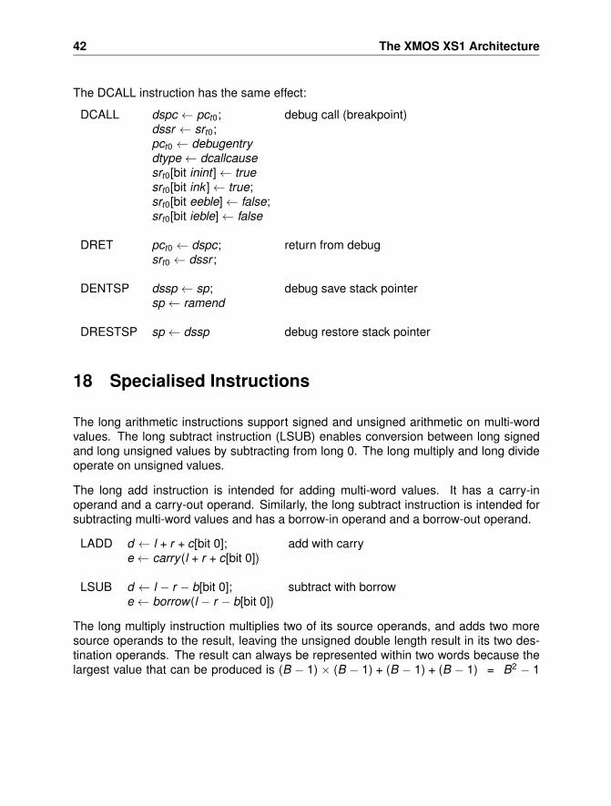
The DCALL instruction has the same effect:
DCALL dspc ← pct0; debug call (breakpoint)dssr ← srt0;pct0 ← debugentrydtype← dcallcausesrt0[bit inint ]← truesrt0[bit ink ]← true;srt0[bit eeble]← false;srt0[bit ieble]← false
DRET pct0 ← dspc; return from debugsrt0 ← dssr ;
DENTSP dssp ← sp; debug save stack pointersp ← ramend
DRESTSP sp ← dssp debug restore stack pointer
18 Specialised Instructions
The long arithmetic instructions support signed and unsigned arithmetic on multi-wordvalues. The long subtract instruction (LSUB) enables conversion between long signedand long unsigned values by subtracting from long 0. The long multiply and long divideoperate on unsigned values.
The long add instruction is intended for adding multi-word values. It has a carry-inoperand and a carry-out operand. Similarly, the long subtract instruction is intended forsubtracting multi-word values and has a borrow-in operand and a borrow-out operand.
LADD d ← l + r + c[bit 0]; add with carrye← carry (l + r + c[bit 0])
LSUB d ← l − r − b[bit 0]; subtract with borrowe← borrow(l − r − b[bit 0])
The long multiply instruction multiplies two of its source operands, and adds two moresource operands to the result, leaving the unsigned double length result in its two des-tination operands. The result can always be represented within two words because thelargest value that can be produced is (B − 1) × (B − 1) + (B − 1) + (B − 1) = B2 − 1
18 Specialised Instructions 43
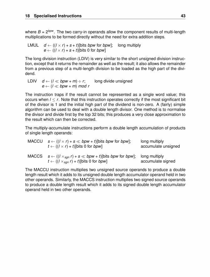
where B = 2bpw . The two carry-in operands allow the component results of multi-lengthmultiplications to be formed directly without the need for extra addition steps.
LMUL d ← ((l × r ) + s + t)[bits bpw for bpw ]; long multiplye← ((l × r ) + s + t)[bits 0 for bpw ]
The long division instruction (LDIV) is very similar to the short unsigned division instruc-tion, except that it returns the remainder as well as the result; it also allows the remainderfrom a previous step of a multi-length division to be loaded as the high part of the divi-dend.
LDIV d ← (l � bpw + m)÷ r ; long divide unsignede← (l � bpw + m) mod r
The instruction traps if the result cannot be represented as a single word value; thisoccurs when l ≤ r . Note that this instruction operates correctly if the most significant bitof the divisor is 1 and the initial high part of the dividend is non-zero. A (fairly) simplealgorithm can be used to deal with a double length divisor. One method is to normalisethe divisor and divide first by the top 32 bits; this produces a very close approximation tothe result which can then be corrected.
The multiply-accumulate instructions perform a double length accumulation of productsof single length operands:
MACCU s ← ((l × r ) + s � bpw + t)[bits bpw for bpw ]; long multiplyt ← ((l × r ) + t)[bits 0 for bpw ] accumulate unsigned
MACCS s ← ((l ×sgn r ) + s � bpw + t)[bits bpw for bpw ]; long multiplyt ← ((l ×sgn r ) + t)[bits 0 for bpw ] accumulate signed
The MACCU instruction multiplies two unsigned source operands to produce a doublelength result which it adds to its unsigned double length accumulator operand held in twoother operands. Similarly, the MACCS instruction multiplies two signed source operandsto produce a double length result which it adds to its signed double length accumulatoroperand held in two other operands.
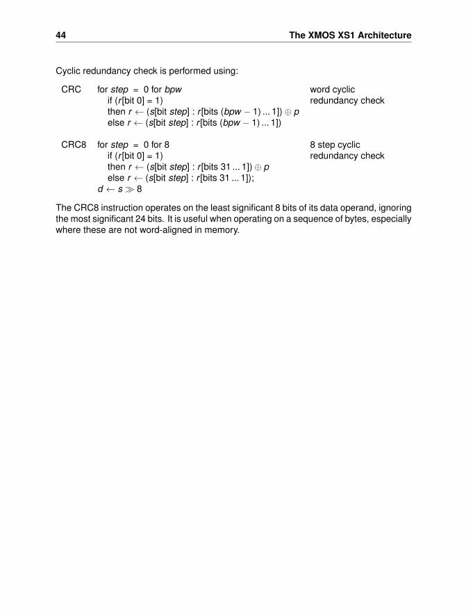
44 The XMOS XS1 Architecture
Cyclic redundancy check is performed using:
CRC for step = 0 for bpw word cyclicif (r [bit 0] = 1) redundancy checkthen r ← (s[bit step] : r [bits (bpw − 1) ... 1])⊕ pelse r ← (s[bit step] : r [bits (bpw − 1) ... 1])
CRC8 for step = 0 for 8 8 step cyclicif (r [bit 0] = 1) redundancy checkthen r ← (s[bit step] : r [bits 31 ... 1])⊕ pelse r ← (s[bit step] : r [bits 31 ... 1]);
d ← s � 8
The CRC8 instruction operates on the least significant 8 bits of its data operand, ignoringthe most significant 24 bits. It is useful when operating on a sequence of bytes, especiallywhere these are not word-aligned in memory.
19 Instruction Details 45
19 Instruction Details
This section details the semantics and encoding of all instructions of the XCore instruc-tion set architecture. The meaning and assembly syntax of each instruction is docu-mented in alphabetical order in Section 19.1. Section 19.2 presents the encoding ofeach instruction; the information in this chapter is needed for the construction of low-level tools such as assemblers and debuggers. Section 19.3 presents all exceptions,and lists which instructions can trigger each specific exception.
The instructions use the following registers:
r0 ... r11 operand registerspc program counter. The program counter is pre incremented, that is, it
contains the address of the next instruction in the program. All instruc-tions that use an address offset relative to the program counter (suchas relative branches, load address relative, etc) use an offset of ’0’ toaddress the next instruction.
sr status registersp stack pointerdp data pointercp constant pool pointerlr link register
19.1 Instructions
This section presents the instructions in alphabetical order. Each instruction is presenteda short textual description, followed by the assembly syntax, its meaning in a more formalnotation, its encoding(s) and potential exceptions that can be raised by this exception.
The processor operates on words - registers are one-word wide, data can be transferredto ports and channels in words, and most memory operations operate on words. A wordis bpw bits long, or Bpw bytes long.
46 The XMOS XS1 Architecture
The following notation is used in the description to describe operands and constants:
bitp denotes a bit-position - one of bpw , 1, 2, 3, 4, 5,6, 7, 8, 16, 24, and 32; these are encoded usingnumbers 0...11.
b register used as a base address.c register used as a conditional.d , e register used as a destination.r register used as a resource identifier.s register used as a source.t register used as a thread identifier.us a small unsigned constant in the range 0...11ux an unsigned constant in the range 0...(2x − 1)v , w , x , y registers used for two or more sources.
All mathematical operators are assumed to work on Integers (Z) and, unless otherwisestated, bit patterns found in registers are interpreted unsigned. Signed numbers arerepresented using two’s complement, and if an operand is interpreted as a signed num-ber, this is denoted by a subscript signed . In addition to the standard numerical operatorsfollowing bitwise operators are assumed:
∨bit Bitwise or.∧bit Bitwise and.⊕bit Bitwise xor.¬bit Bitwise complement.
Square brackets are used for two purposes. When preceded with the word mem squarebrackets address a memory location. Otherwise, they indicate that one or more bits aresliced out of a bit pattern. Bits can be spliced together using a “:” operator. The bitpattern x : y is a pattern where x are the higher order bits and y are the lower order bits.
The notation mem[x ] represents word-based access to memory, and the address x mustbe word-aligned (that is, the address must be a multiple of Bpw). Instructions that reador write data to memory that is not a word in size (such as a byte or a 16-bit value)explicitly specify which bits in memory are accessed.
The instruction encoding specifies the opcode bits of the encoding - the way that theoperands are encoded is specified on the corresponding page in the instruction formatssection. Each operand in the instruction section maps positionally on an operand in theformat section.
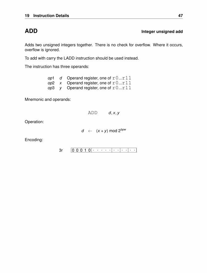
19 Instruction Details 47
ADD Integer unsigned add
Adds two unsigned integers together. There is no check for overflow. Where it occurs,overflow is ignored.
To add with carry the LADD instruction should be used instead.
The instruction has three operands:
op1 d Operand register, one of r0...r11op2 x Operand register, one of r0...r11op3 y Operand register, one of r0...r11
Mnemonic and operands:
ADD d , x , y
Operation:
d ← (x + y ) mod 2bpw
Encoding:
0 0 0 1 0 . . . . . . . . . . .3r
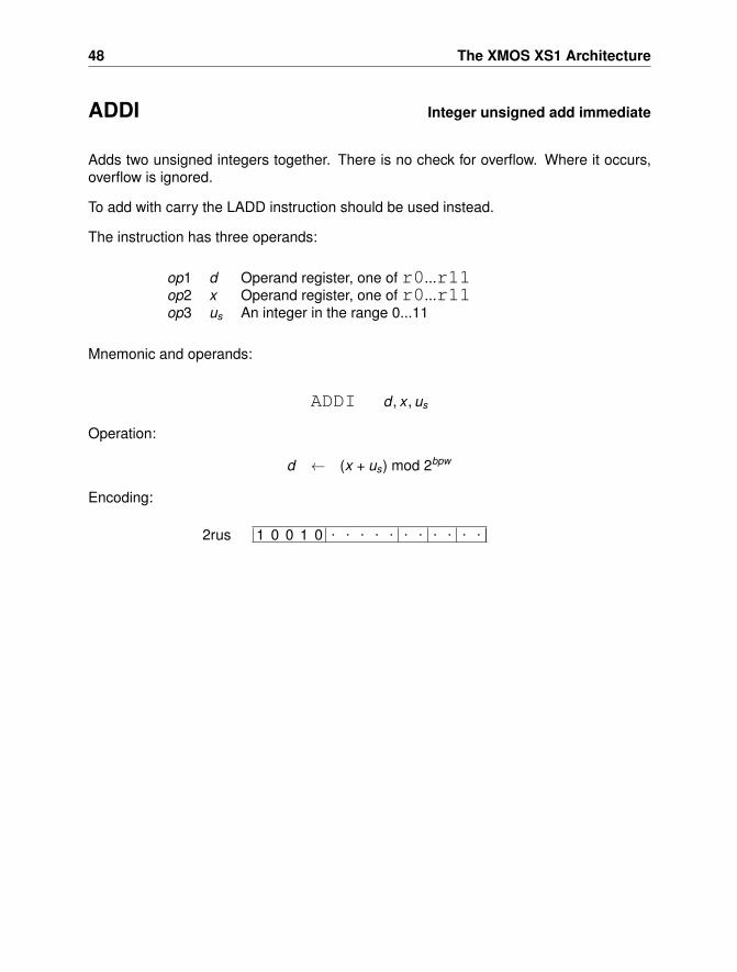
48 The XMOS XS1 Architecture
ADDI Integer unsigned add immediate
Adds two unsigned integers together. There is no check for overflow. Where it occurs,overflow is ignored.
To add with carry the LADD instruction should be used instead.
The instruction has three operands:
op1 d Operand register, one of r0...r11op2 x Operand register, one of r0...r11op3 us An integer in the range 0...11
Mnemonic and operands:
ADDI d , x , us
Operation:
d ← (x + us) mod 2bpw
Encoding:
1 0 0 1 0 . . . . . . . . . . .2rus
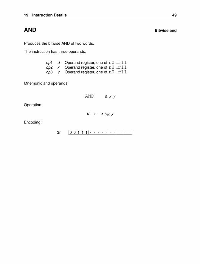
19 Instruction Details 49
AND Bitwise and
Produces the bitwise AND of two words.
The instruction has three operands:
op1 d Operand register, one of r0...r11op2 x Operand register, one of r0...r11op3 y Operand register, one of r0...r11
Mnemonic and operands:
AND d , x , y
Operation:
d ← x ∧bit y
Encoding:
0 0 1 1 1 . . . . . . . . . . .3r
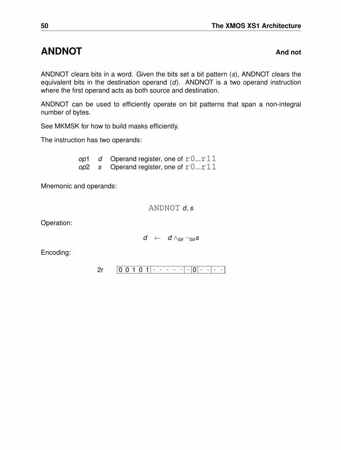
50 The XMOS XS1 Architecture
ANDNOT And not
ANDNOT clears bits in a word. Given the bits set a bit pattern (s), ANDNOT clears theequivalent bits in the destination operand (d). ANDNOT is a two operand instructionwhere the first operand acts as both source and destination.
ANDNOT can be used to efficiently operate on bit patterns that span a non-integralnumber of bytes.
See MKMSK for how to build masks efficiently.
The instruction has two operands:
op1 d Operand register, one of r0...r11op2 s Operand register, one of r0...r11
Mnemonic and operands:
ANDNOT d , s
Operation:
d ← d ∧bit ¬bits
Encoding:
0 0 1 0 1 . . . . . . 0 . . . .2r
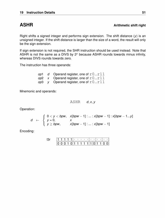
19 Instruction Details 51
ASHR Arithmetic shift right
Right shifts a signed integer and performs sign extension. The shift distance (y) is anunsigned integer. If the shift distance is larger than the size of a word, the result will onlybe the sign extension.
If sign extension is not required, the SHR instruction should be used instead. Note thatASHR is not the same as a DIVS by 2y because ASHR rounds towards minus infinity,whereas DIVS rounds towards zero.
The instruction has three operands:
op1 d Operand register, one of r0...r11op2 x Operand register, one of r0...r11op3 y Operand register, one of r0...r11
Mnemonic and operands:
ASHR d , x , y
Operation:
d ←
0 < y < bpw , x [bpw − 1] : ... : x [bpw − 1] : x [bpw − 1...y ]y = 0, xy ≥ bpw , x [bpw − 1] : ... : x [bpw − 1]
Encoding:
1 1 1 1 1 . . . . . . . . . . .0 0 0 1 0 1 1 1 1 1 1 0 1 1 0 0
l3r
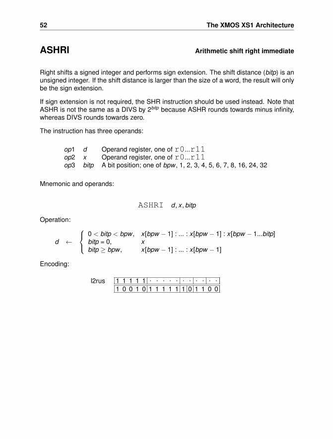
52 The XMOS XS1 Architecture
ASHRI Arithmetic shift right immediate
Right shifts a signed integer and performs sign extension. The shift distance (bitp) is anunsigned integer. If the shift distance is larger than the size of a word, the result will onlybe the sign extension.
If sign extension is not required, the SHR instruction should be used instead. Note thatASHR is not the same as a DIVS by 2bitp because ASHR rounds towards minus infinity,whereas DIVS rounds towards zero.
The instruction has three operands:
op1 d Operand register, one of r0...r11op2 x Operand register, one of r0...r11op3 bitp A bit position; one of bpw , 1, 2, 3, 4, 5, 6, 7, 8, 16, 24, 32
Mnemonic and operands:
ASHRI d , x , bitp
Operation:
d ←
0 < bitp < bpw , x [bpw − 1] : ... : x [bpw − 1] : x [bpw − 1...bitp]bitp = 0, xbitp ≥ bpw , x [bpw − 1] : ... : x [bpw − 1]
Encoding:
1 1 1 1 1 . . . . . . . . . . .
1 0 0 1 0 1 1 1 1 1 1 0 1 1 0 0l2rus
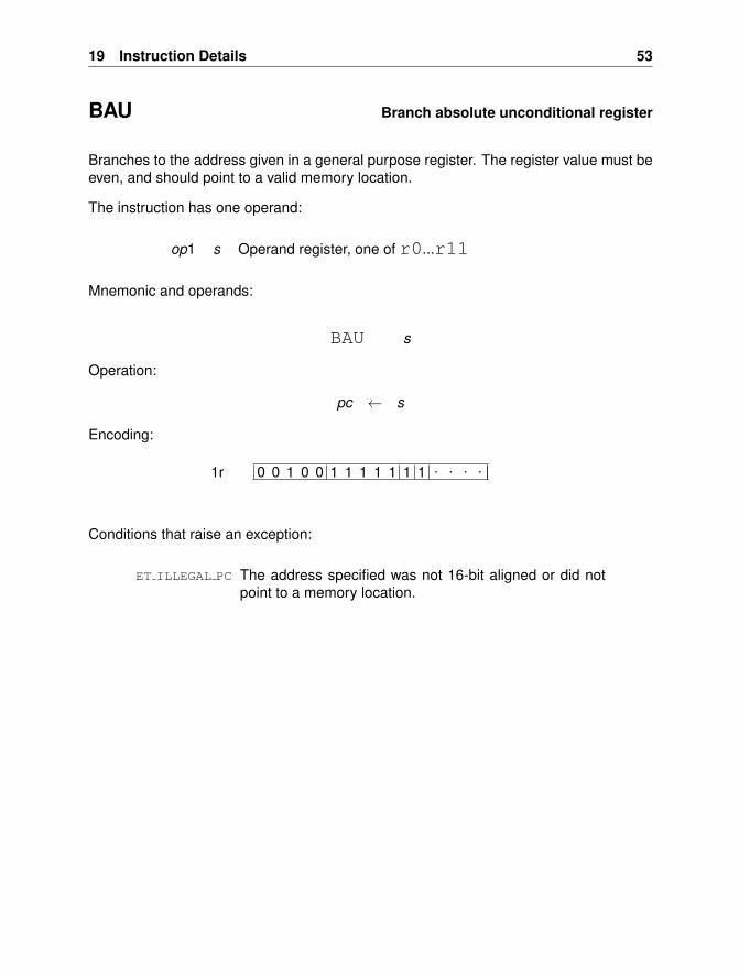
19 Instruction Details 53
BAU Branch absolute unconditional register
Branches to the address given in a general purpose register. The register value must beeven, and should point to a valid memory location.
The instruction has one operand:
op1 s Operand register, one of r0...r11
Mnemonic and operands:
BAU s
Operation:
pc ← s
Encoding:
0 0 1 0 0 1 1 1 1 1 1 1 . . . .1r
Conditions that raise an exception:
ET ILLEGAL PC The address specified was not 16-bit aligned or did notpoint to a memory location.
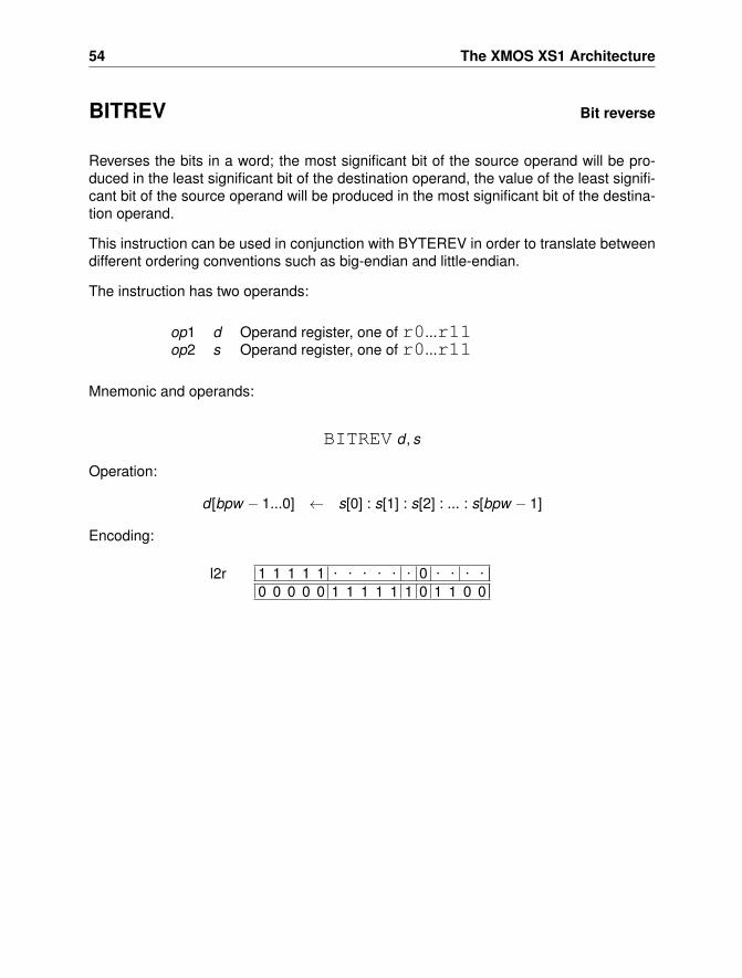
54 The XMOS XS1 Architecture
BITREV Bit reverse
Reverses the bits in a word; the most significant bit of the source operand will be pro-duced in the least significant bit of the destination operand, the value of the least signifi-cant bit of the source operand will be produced in the most significant bit of the destina-tion operand.
This instruction can be used in conjunction with BYTEREV in order to translate betweendifferent ordering conventions such as big-endian and little-endian.
The instruction has two operands:
op1 d Operand register, one of r0...r11op2 s Operand register, one of r0...r11
Mnemonic and operands:
BITREV d , s
Operation:
d [bpw − 1...0] ← s[0] : s[1] : s[2] : ... : s[bpw − 1]
Encoding:
1 1 1 1 1 . . . . . . 0 . . . .0 0 0 0 0 1 1 1 1 1 1 0 1 1 0 0
l2r
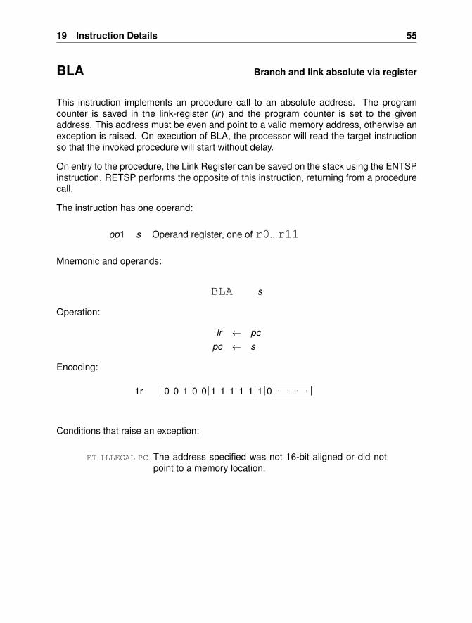
19 Instruction Details 55
BLA Branch and link absolute via register
This instruction implements an procedure call to an absolute address. The programcounter is saved in the link-register (lr ) and the program counter is set to the givenaddress. This address must be even and point to a valid memory address, otherwise anexception is raised. On execution of BLA, the processor will read the target instructionso that the invoked procedure will start without delay.
On entry to the procedure, the Link Register can be saved on the stack using the ENTSPinstruction. RETSP performs the opposite of this instruction, returning from a procedurecall.
The instruction has one operand:
op1 s Operand register, one of r0...r11
Mnemonic and operands:
BLA s
Operation:
lr ← pcpc ← s
Encoding:
0 0 1 0 0 1 1 1 1 1 1 0 . . . .1r
Conditions that raise an exception:
ET ILLEGAL PC The address specified was not 16-bit aligned or did notpoint to a memory location.
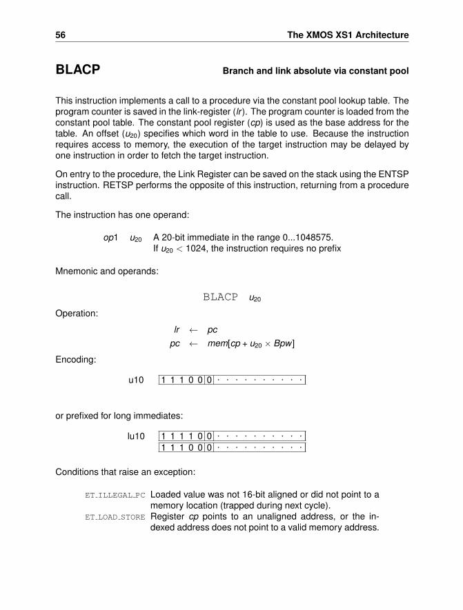
56 The XMOS XS1 Architecture
BLACP Branch and link absolute via constant pool
This instruction implements a call to a procedure via the constant pool lookup table. Theprogram counter is saved in the link-register (lr ). The program counter is loaded from theconstant pool table. The constant pool register (cp) is used as the base address for thetable. An offset (u20) specifies which word in the table to use. Because the instructionrequires access to memory, the execution of the target instruction may be delayed byone instruction in order to fetch the target instruction.
On entry to the procedure, the Link Register can be saved on the stack using the ENTSPinstruction. RETSP performs the opposite of this instruction, returning from a procedurecall.
The instruction has one operand:
op1 u20 A 20-bit immediate in the range 0...1048575.If u20 < 1024, the instruction requires no prefix
Mnemonic and operands:
BLACP u20
Operation:
lr ← pcpc ← mem[cp + u20 × Bpw ]
Encoding:
1 1 1 0 0 0 . . . . . . . . . .u10
or prefixed for long immediates:
1 1 1 1 0 0 . . . . . . . . . .
1 1 1 0 0 0 . . . . . . . . . .lu10
Conditions that raise an exception:
ET ILLEGAL PC Loaded value was not 16-bit aligned or did not point to amemory location (trapped during next cycle).
ET LOAD STORE Register cp points to an unaligned address, or the in-dexed address does not point to a valid memory address.
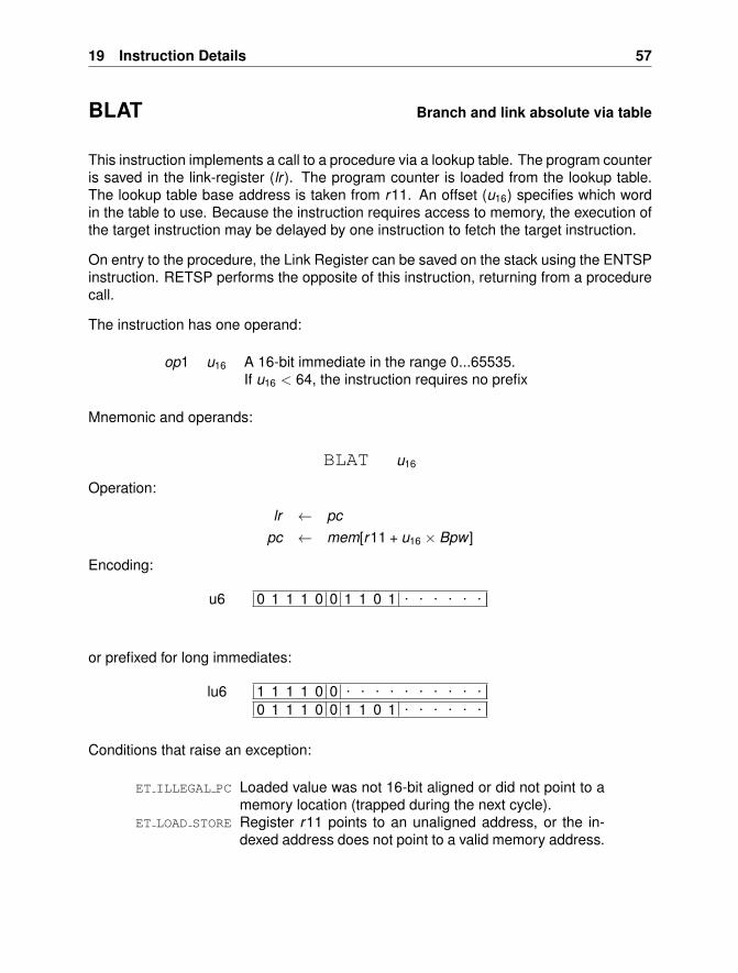
19 Instruction Details 57
BLAT Branch and link absolute via table
This instruction implements a call to a procedure via a lookup table. The program counteris saved in the link-register (lr ). The program counter is loaded from the lookup table.The lookup table base address is taken from r11. An offset (u16) specifies which wordin the table to use. Because the instruction requires access to memory, the execution ofthe target instruction may be delayed by one instruction to fetch the target instruction.
On entry to the procedure, the Link Register can be saved on the stack using the ENTSPinstruction. RETSP performs the opposite of this instruction, returning from a procedurecall.
The instruction has one operand:
op1 u16 A 16-bit immediate in the range 0...65535.If u16 < 64, the instruction requires no prefix
Mnemonic and operands:
BLAT u16
Operation:
lr ← pcpc ← mem[r11 + u16 × Bpw ]
Encoding:
0 1 1 1 0 0 1 1 0 1 . . . . . .u6
or prefixed for long immediates:
1 1 1 1 0 0 . . . . . . . . . .0 1 1 1 0 0 1 1 0 1 . . . . . .
lu6
Conditions that raise an exception:
ET ILLEGAL PC Loaded value was not 16-bit aligned or did not point to amemory location (trapped during the next cycle).
ET LOAD STORE Register r11 points to an unaligned address, or the in-dexed address does not point to a valid memory address.
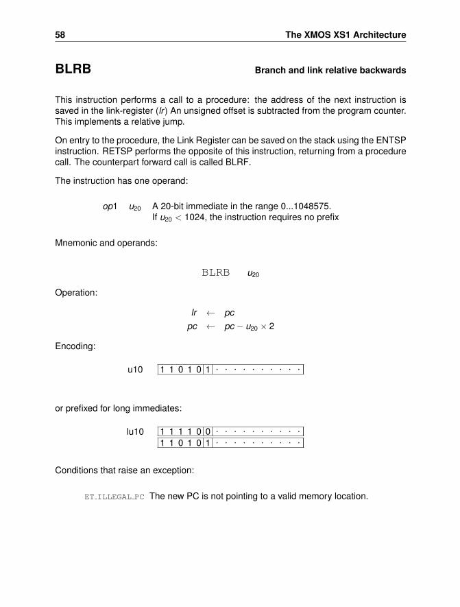
58 The XMOS XS1 Architecture
BLRB Branch and link relative backwards
This instruction performs a call to a procedure: the address of the next instruction issaved in the link-register (lr ) An unsigned offset is subtracted from the program counter.This implements a relative jump.
On entry to the procedure, the Link Register can be saved on the stack using the ENTSPinstruction. RETSP performs the opposite of this instruction, returning from a procedurecall. The counterpart forward call is called BLRF.
The instruction has one operand:
op1 u20 A 20-bit immediate in the range 0...1048575.If u20 < 1024, the instruction requires no prefix
Mnemonic and operands:
BLRB u20
Operation:
lr ← pcpc ← pc − u20 × 2
Encoding:
1 1 0 1 0 1 . . . . . . . . . .u10
or prefixed for long immediates:
1 1 1 1 0 0 . . . . . . . . . .
1 1 0 1 0 1 . . . . . . . . . .lu10
Conditions that raise an exception:
ET ILLEGAL PC The new PC is not pointing to a valid memory location.
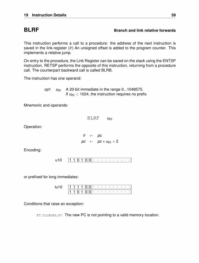
19 Instruction Details 59
BLRF Branch and link relative forwards
This instruction performs a call to a procedure: the address of the next instruction issaved in the link-register (lr ) An unsigned offset is added to the program counter. Thisimplements a relative jump.
On entry to the procedure, the Link Register can be saved on the stack using the ENTSPinstruction. RETSP performs the opposite of this instruction, returning from a procedurecall. The counterpart backward call is called BLRB.
The instruction has one operand:
op1 u20 A 20-bit immediate in the range 0...1048575.If u20 < 1024, the instruction requires no prefix
Mnemonic and operands:
BLRF u20
Operation:
lr ← pcpc ← pc + u20 × 2
Encoding:
1 1 0 1 0 0 . . . . . . . . . .u10
or prefixed for long immediates:
1 1 1 1 0 0 . . . . . . . . . .
1 1 0 1 0 0 . . . . . . . . . .lu10
Conditions that raise an exception:
ET ILLEGAL PC The new PC is not pointing to a valid memory location.
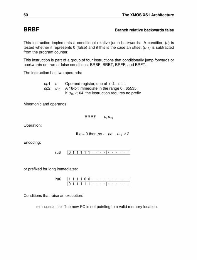
60 The XMOS XS1 Architecture
BRBF Branch relative backwards false
This instruction implements a conditional relative jump backwards. A condition (c) istested whether it represents 0 (false) and if this is the case an offset (u16) is subtractedfrom the program counter.
This instruction is part of a group of four instructions that conditionally jump forwards orbackwards on true or false conditions: BRBF, BRBT, BRFF, and BRFT.
The instruction has two operands:
op1 c Operand register, one of r0...r11op2 u16 A 16-bit immediate in the range 0...65535.
If u16 < 64, the instruction requires no prefix
Mnemonic and operands:
BRBF c, u16
Operation:
if c = 0 then pc ← pc − u16 × 2
Encoding:
0 1 1 1 1 1 . . . . . . . . . .ru6
or prefixed for long immediates:
1 1 1 1 0 0 . . . . . . . . . .0 1 1 1 1 1 . . . . . . . . . .
lru6
Conditions that raise an exception:
ET ILLEGAL PC The new PC is not pointing to a valid memory location.
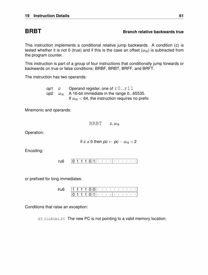
19 Instruction Details 61
BRBT Branch relative backwards true
This instruction implements a conditional relative jump backwards. A condition (c) istested whether it is not 0 (true) and if this is the case an offset (u16) is subtracted fromthe program counter.
This instruction is part of a group of four instructions that conditionally jump forwards orbackwards on true or false conditions: BRBF, BRBT, BRFF, and BRFT.
The instruction has two operands:
op1 c Operand register, one of r0...r11op2 u16 A 16-bit immediate in the range 0...65535.
If u16 < 64, the instruction requires no prefix
Mnemonic and operands:
BRBT c, u16
Operation:
if c 6= 0 then pc ← pc − u16 × 2
Encoding:
0 1 1 1 0 1 . . . . . . . . . .ru6
or prefixed for long immediates:
1 1 1 1 0 0 . . . . . . . . . .0 1 1 1 0 1 . . . . . . . . . .
lru6
Conditions that raise an exception:
ET ILLEGAL PC The new PC is not pointing to a valid memory location.
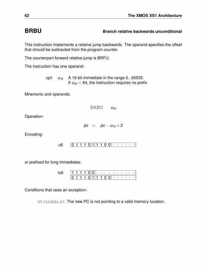
62 The XMOS XS1 Architecture
BRBU Branch relative backwards unconditional
This instruction implements a relative jump backwards. The operand specifies the offsetthat should be subtracted from the program counter.
The counterpart forward relative jump is BRFU.
The instruction has one operand:
op1 u16 A 16-bit immediate in the range 0...65535.If u16 < 64, the instruction requires no prefix
Mnemonic and operands:
BRBU u16
Operation:
pc ← pc − u16 × 2
Encoding:
0 1 1 1 0 1 1 1 0 0 . . . . . .u6
or prefixed for long immediates:
1 1 1 1 0 0 . . . . . . . . . .0 1 1 1 0 1 1 1 0 0 . . . . . .
lu6
Conditions that raise an exception:
ET ILLEGAL PC The new PC is not pointing to a valid memory location.
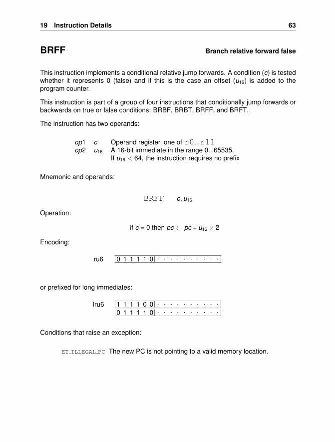
19 Instruction Details 63
BRFF Branch relative forward false
This instruction implements a conditional relative jump forwards. A condition (c) is testedwhether it represents 0 (false) and if this is the case an offset (u16) is added to theprogram counter.
This instruction is part of a group of four instructions that conditionally jump forwards orbackwards on true or false conditions: BRBF, BRBT, BRFF, and BRFT.
The instruction has two operands:
op1 c Operand register, one of r0...r11op2 u16 A 16-bit immediate in the range 0...65535.
If u16 < 64, the instruction requires no prefix
Mnemonic and operands:
BRFF c, u16
Operation:
if c = 0 then pc ← pc + u16 × 2
Encoding:
0 1 1 1 1 0 . . . . . . . . . .ru6
or prefixed for long immediates:
1 1 1 1 0 0 . . . . . . . . . .0 1 1 1 1 0 . . . . . . . . . .
lru6
Conditions that raise an exception:
ET ILLEGAL PC The new PC is not pointing to a valid memory location.
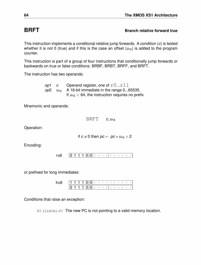
64 The XMOS XS1 Architecture
BRFT Branch relative forward true
This instruction implements a conditional relative jump forwards. A condition (c) is testedwhether it is not 0 (true) and if this is the case an offset (u16) is added to the programcounter.
This instruction is part of a group of four instructions that conditionally jump forwards orbackwards on true or false conditions: BRBF, BRBT, BRFF, and BRFT.
The instruction has two operands:
op1 c Operand register, one of r0...r11op2 u16 A 16-bit immediate in the range 0...65535.
If u16 < 64, the instruction requires no prefix
Mnemonic and operands:
BRFT c, u16
Operation:
if c 6= 0 then pc ← pc + u16 × 2
Encoding:
0 1 1 1 0 0 . . . . . . . . . .ru6
or prefixed for long immediates:
1 1 1 1 0 0 . . . . . . . . . .0 1 1 1 0 0 . . . . . . . . . .
lru6
Conditions that raise an exception:
ET ILLEGAL PC The new PC is not pointing to a valid memory location.
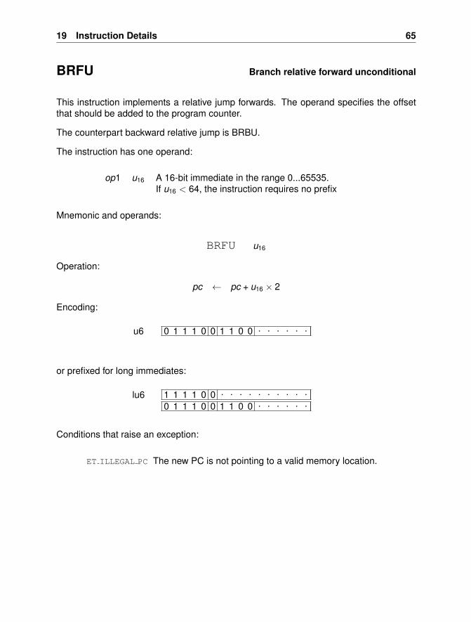
19 Instruction Details 65
BRFU Branch relative forward unconditional
This instruction implements a relative jump forwards. The operand specifies the offsetthat should be added to the program counter.
The counterpart backward relative jump is BRBU.
The instruction has one operand:
op1 u16 A 16-bit immediate in the range 0...65535.If u16 < 64, the instruction requires no prefix
Mnemonic and operands:
BRFU u16
Operation:
pc ← pc + u16 × 2
Encoding:
0 1 1 1 0 0 1 1 0 0 . . . . . .u6
or prefixed for long immediates:
1 1 1 1 0 0 . . . . . . . . . .0 1 1 1 0 0 1 1 0 0 . . . . . .
lu6
Conditions that raise an exception:
ET ILLEGAL PC The new PC is not pointing to a valid memory location.

66 The XMOS XS1 Architecture
BRU Branch relative unconditional register
This instruction implements a jump using a signed offset stored in a register. Becauseinstructions are aligned on 16-bit boundaries, the offset in the register is multiplied by 2.Negative values cause backwards jumps.
The instruction has one operand:
op1 s Operand register, one of r0...r11
Mnemonic and operands:
BRU s
Operation:
pc ← pc + ssigned × 2
Encoding:
0 0 1 0 1 1 1 1 1 1 1 0 . . . .1r
Conditions that raise an exception:
ET ILLEGAL PC The new PC is not pointing to a valid memory location.
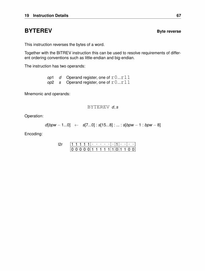
19 Instruction Details 67
BYTEREV Byte reverse
This instruction reverses the bytes of a word.
Together with the BITREV instruction this can be used to resolve requirements of differ-ent ordering conventions such as little-endian and big-endian.
The instruction has two operands:
op1 d Operand register, one of r0...r11op2 s Operand register, one of r0...r11
Mnemonic and operands:
BYTEREV d , s
Operation:
d [bpw − 1...0] ← s[7...0] : s[15...8] : ... : s[bpw − 1 : bpw − 8]
Encoding:
1 1 1 1 1 . . . . . . 1 . . . .0 0 0 0 0 1 1 1 1 1 1 0 1 1 0 0
l2r
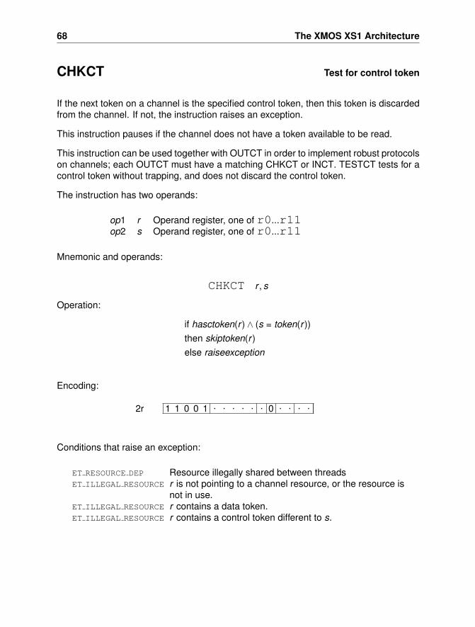
68 The XMOS XS1 Architecture
CHKCT Test for control token
If the next token on a channel is the specified control token, then this token is discardedfrom the channel. If not, the instruction raises an exception.
This instruction pauses if the channel does not have a token available to be read.
This instruction can be used together with OUTCT in order to implement robust protocolson channels; each OUTCT must have a matching CHKCT or INCT. TESTCT tests for acontrol token without trapping, and does not discard the control token.
The instruction has two operands:
op1 r Operand register, one of r0...r11op2 s Operand register, one of r0...r11
Mnemonic and operands:
CHKCT r , s
Operation:
if hasctoken(r ) ∧ (s = token(r ))then skiptoken(r )else raiseexception
Encoding:
1 1 0 0 1 . . . . . . 0 . . . .2r
Conditions that raise an exception:
ET RESOURCE DEP Resource illegally shared between threadsET ILLEGAL RESOURCE r is not pointing to a channel resource, or the resource is
not in use.ET ILLEGAL RESOURCE r contains a data token.ET ILLEGAL RESOURCE r contains a control token different to s.
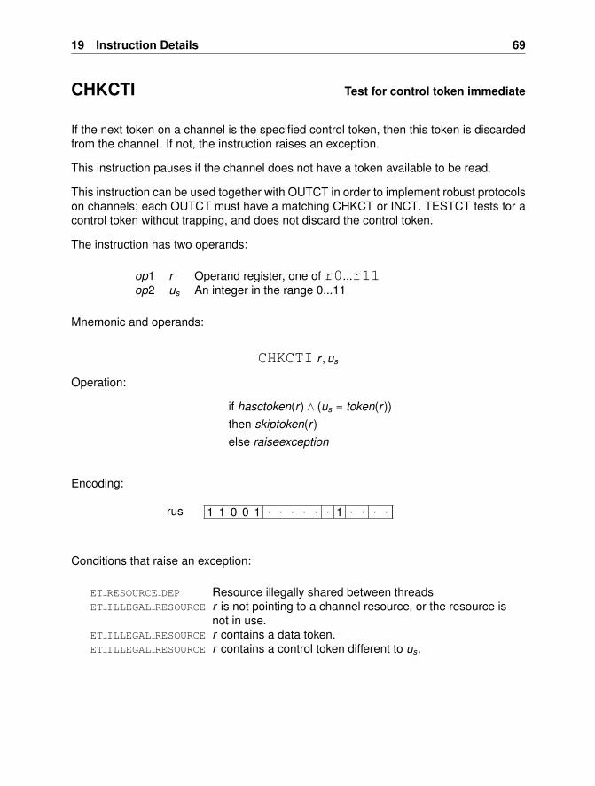
19 Instruction Details 69
CHKCTI Test for control token immediate
If the next token on a channel is the specified control token, then this token is discardedfrom the channel. If not, the instruction raises an exception.
This instruction pauses if the channel does not have a token available to be read.
This instruction can be used together with OUTCT in order to implement robust protocolson channels; each OUTCT must have a matching CHKCT or INCT. TESTCT tests for acontrol token without trapping, and does not discard the control token.
The instruction has two operands:
op1 r Operand register, one of r0...r11op2 us An integer in the range 0...11
Mnemonic and operands:
CHKCTI r , us
Operation:
if hasctoken(r ) ∧ (us = token(r ))then skiptoken(r )else raiseexception
Encoding:
1 1 0 0 1 . . . . . . 1 . . . .rus
Conditions that raise an exception:
ET RESOURCE DEP Resource illegally shared between threadsET ILLEGAL RESOURCE r is not pointing to a channel resource, or the resource is
not in use.ET ILLEGAL RESOURCE r contains a data token.ET ILLEGAL RESOURCE r contains a control token different to us.
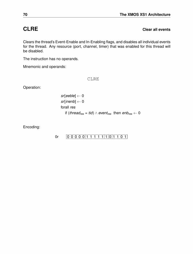
70 The XMOS XS1 Architecture
CLRE Clear all events
Clears the thread’s Event-Enable and In-Enabling flags, and disables all individual eventsfor the thread. Any resource (port, channel, timer) that was enabled for this thread willbe disabled.
The instruction has no operands.
Mnemonic and operands:
CLRE
Operation:
sr [eeble]← 0sr [inenb]← 0forall res
if (threadres = tid) ∧ eventres then enbres ← 0
Encoding:
0 0 0 0 0 1 1 1 1 1 1 0 1 1 0 10r
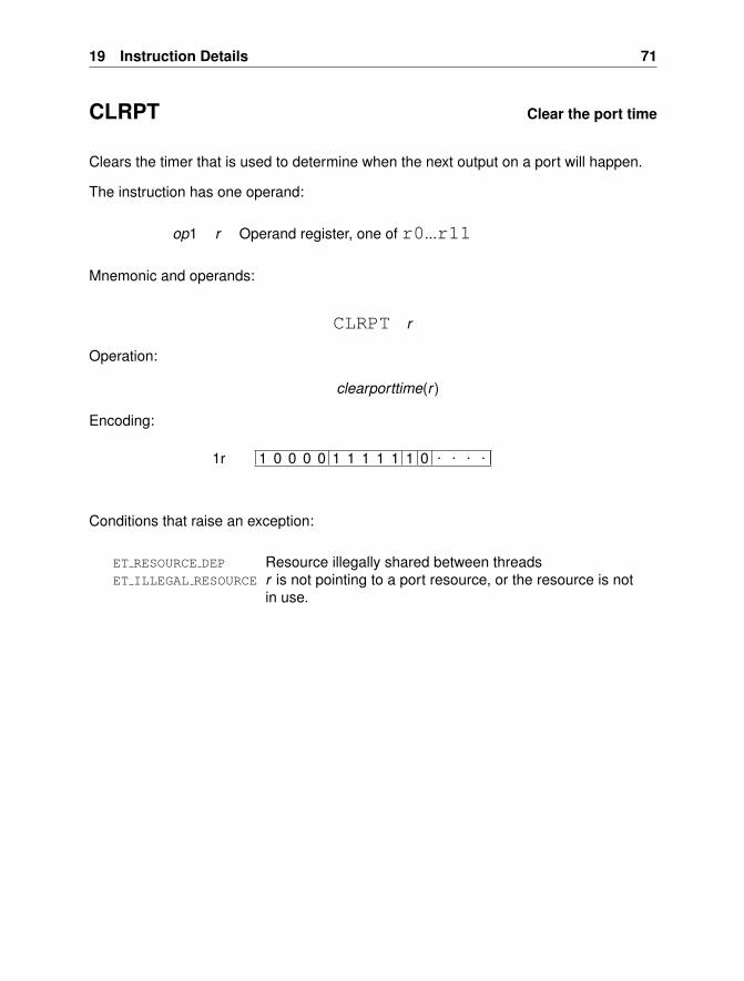
19 Instruction Details 71
CLRPT Clear the port time
Clears the timer that is used to determine when the next output on a port will happen.
The instruction has one operand:
op1 r Operand register, one of r0...r11
Mnemonic and operands:
CLRPT r
Operation:
clearporttime(r )
Encoding:
1 0 0 0 0 1 1 1 1 1 1 0 . . . .1r
Conditions that raise an exception:
ET RESOURCE DEP Resource illegally shared between threadsET ILLEGAL RESOURCE r is not pointing to a port resource, or the resource is not
in use.
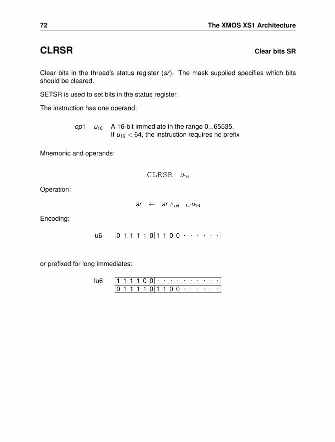
72 The XMOS XS1 Architecture
CLRSR Clear bits SR
Clear bits in the thread’s status register (sr ). The mask supplied specifies which bitsshould be cleared.
SETSR is used to set bits in the status register.
The instruction has one operand:
op1 u16 A 16-bit immediate in the range 0...65535.If u16 < 64, the instruction requires no prefix
Mnemonic and operands:
CLRSR u16
Operation:
sr ← sr ∧bit ¬bitu16
Encoding:
0 1 1 1 1 0 1 1 0 0 . . . . . .u6
or prefixed for long immediates:
1 1 1 1 0 0 . . . . . . . . . .0 1 1 1 1 0 1 1 0 0 . . . . . .
lu6
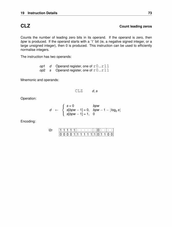
19 Instruction Details 73
CLZ Count leading zeros
Counts the number of leading zero bits in its operand. If the operand is zero, thenbpw is produced. If the operand starts with a ’1’ bit (ie, a negative signed integer, or alarge unsigned integer), then 0 is produced. This instruction can be used to efficientlynormalise integers.
The instruction has two operands:
op1 d Operand register, one of r0...r11op2 s Operand register, one of r0...r11
Mnemonic and operands:
CLZ d , s
Operation:
d ←
s = 0 bpws[bpw − 1] = 0, bpw − 1− blog2 scs[bpw − 1] = 1, 0
Encoding:
1 1 1 1 1 . . . . . . 0 . . . .0 0 0 0 1 1 1 1 1 1 1 0 1 1 0 0
l2r
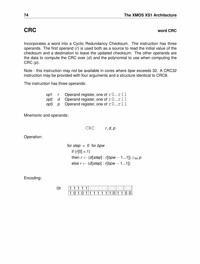
74 The XMOS XS1 Architecture
CRC word CRC
Incorporates a word into a Cyclic Redundancy Checksum. The instruction has threeoperands. The first operand (r ) is used both as a source to read the initial value of thechecksum and a destination to leave the updated checksum. The other operands arethe data to compute the CRC over (d) and the polynomial to use when computing theCRC (p).
Note - this instruction may not be available in cores where bpw exceeds 32. A CRC32instruction may be provided with four arguments and a structure identical to CRC8.
The instruction has three operands:
op1 r Operand register, one of r0...r11op2 d Operand register, one of r0...r11op3 p Operand register, one of r0...r11
Mnemonic and operands:
CRC r , d , p
Operation:
for step = 0 for bpwif (r [0] = 1)then r ← (d [step] : r [bpw − 1...1])⊕bit pelse r ← (d [step] : r [bpw − 1...1])
Encoding:
1 1 1 1 1 . . . . . . . . . . .
1 0 1 0 1 1 1 1 1 1 1 0 1 1 0 0l3r
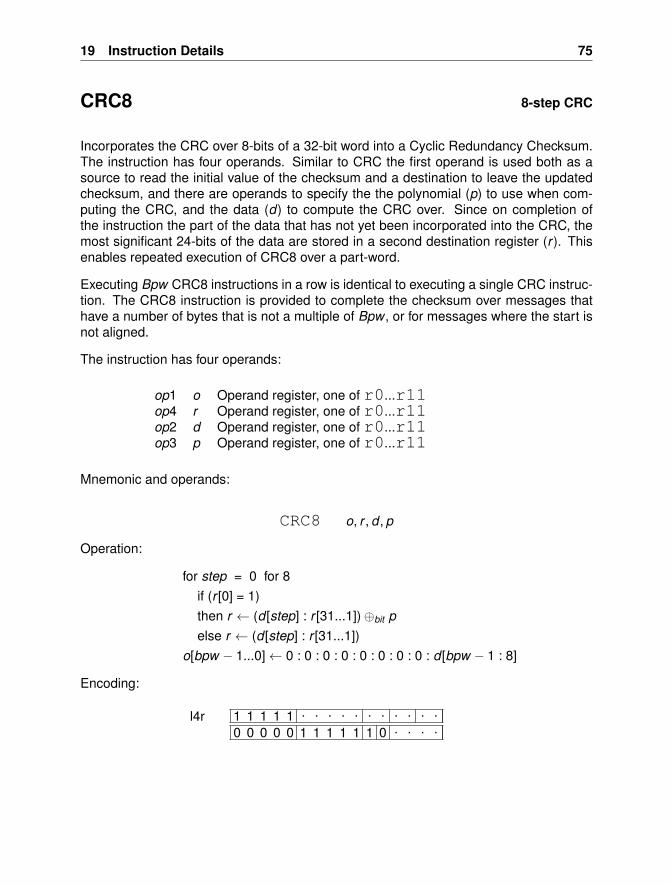
19 Instruction Details 75
CRC8 8-step CRC
Incorporates the CRC over 8-bits of a 32-bit word into a Cyclic Redundancy Checksum.The instruction has four operands. Similar to CRC the first operand is used both as asource to read the initial value of the checksum and a destination to leave the updatedchecksum, and there are operands to specify the the polynomial (p) to use when com-puting the CRC, and the data (d) to compute the CRC over. Since on completion ofthe instruction the part of the data that has not yet been incorporated into the CRC, themost significant 24-bits of the data are stored in a second destination register (r ). Thisenables repeated execution of CRC8 over a part-word.
Executing Bpw CRC8 instructions in a row is identical to executing a single CRC instruc-tion. The CRC8 instruction is provided to complete the checksum over messages thathave a number of bytes that is not a multiple of Bpw , or for messages where the start isnot aligned.
The instruction has four operands:
op1 o Operand register, one of r0...r11op4 r Operand register, one of r0...r11op2 d Operand register, one of r0...r11op3 p Operand register, one of r0...r11
Mnemonic and operands:
CRC8 o, r , d , p
Operation:
for step = 0 for 8if (r [0] = 1)then r ← (d [step] : r [31...1])⊕bit pelse r ← (d [step] : r [31...1])
o[bpw − 1...0]← 0 : 0 : 0 : 0 : 0 : 0 : 0 : 0 : d [bpw − 1 : 8]
Encoding:
1 1 1 1 1 . . . . . . . . . . .0 0 0 0 0 1 1 1 1 1 1 0 . . . .
l4r
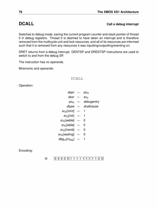
76 The XMOS XS1 Architecture
DCALL Call a debug interrupt
Switches to debug mode, saving the current program counter and stack pointer of thread0 in debug registers. Thread 0 is deemed to have taken an interrupt and is thereforeremoved from the multicycle unit and lock resources, and all of its resources are informedsuch that it is removed from any resources it was inputting/outputting/eventing on.
DRET returns from a debug interrupt. DENTSP and DRESTSP instructions are used toswitch to and from the debug SP.
The instruction has no operands.
Mnemonic and operands:
DCALL
Operation:
dspc ← pct0
dssr ← srt0
pct0 ← debugentrydtype ← dcallcause
srt0[inint ] ← 1srt0[ink ] ← 1
srt0[eeble] ← 0srt0[ieble] ← 0
srt0[inenb] ← 0srt0[waiting] ← 0dbgint [indbg ] ← 1
Encoding:
0 0 0 0 0 1 1 1 1 1 1 1 1 1 0 00r
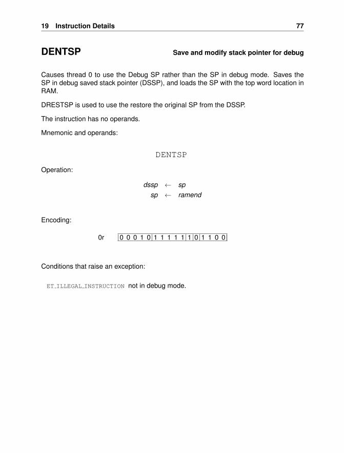
19 Instruction Details 77
DENTSP Save and modify stack pointer for debug
Causes thread 0 to use the Debug SP rather than the SP in debug mode. Saves theSP in debug saved stack pointer (DSSP), and loads the SP with the top word location inRAM.
DRESTSP is used to use the restore the original SP from the DSSP.
The instruction has no operands.
Mnemonic and operands:
DENTSP
Operation:
dssp ← spsp ← ramend
Encoding:
0 0 0 1 0 1 1 1 1 1 1 0 1 1 0 00r
Conditions that raise an exception:
ET ILLEGAL INSTRUCTION not in debug mode.
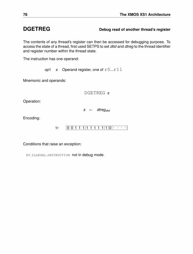
78 The XMOS XS1 Architecture
DGETREG Debug read of another thread’s register
The contents of any thread’s register can then be accessed for debugging purpose. Toaccess the state of a thread, first used SETPS to set dtid and dtreg to the thread identifierand register number within the thread state.
The instruction has one operand:
op1 s Operand register, one of r0...r11
Mnemonic and operands:
DGETREG s
Operation:
s ← dtregdtid
Encoding:
0 0 1 1 1 1 1 1 1 1 1 0 . . . .1r
Conditions that raise an exception:
ET ILLEGAL INSTRUCTION not in debug mode.
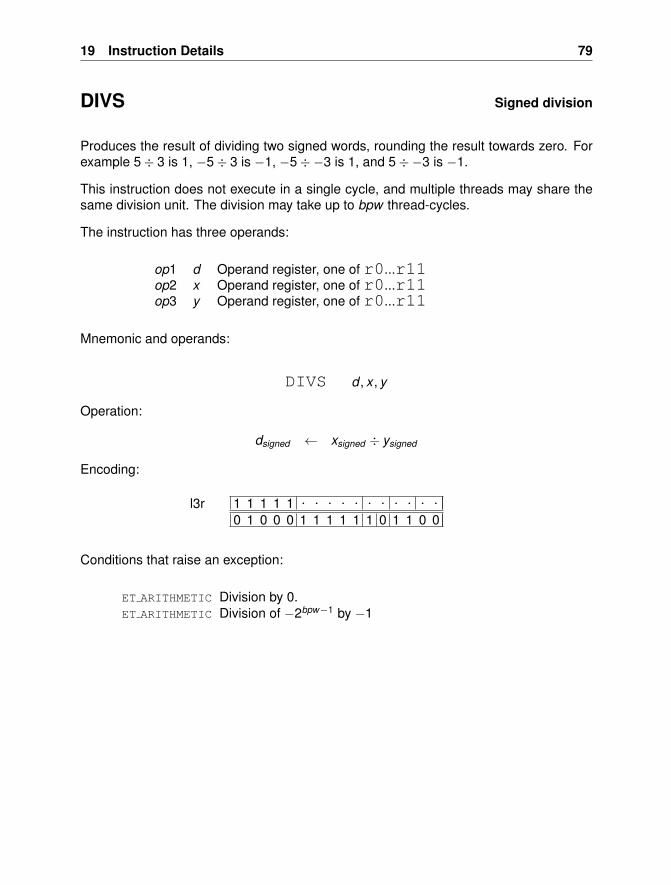
19 Instruction Details 79
DIVS Signed division
Produces the result of dividing two signed words, rounding the result towards zero. Forexample 5÷ 3 is 1, −5÷ 3 is −1, −5÷−3 is 1, and 5÷−3 is −1.
This instruction does not execute in a single cycle, and multiple threads may share thesame division unit. The division may take up to bpw thread-cycles.
The instruction has three operands:
op1 d Operand register, one of r0...r11op2 x Operand register, one of r0...r11op3 y Operand register, one of r0...r11
Mnemonic and operands:
DIVS d , x , y
Operation:
dsigned ← xsigned ÷ ysigned
Encoding:
1 1 1 1 1 . . . . . . . . . . .0 1 0 0 0 1 1 1 1 1 1 0 1 1 0 0
l3r
Conditions that raise an exception:
ET ARITHMETIC Division by 0.ET ARITHMETIC Division of −2bpw−1 by −1
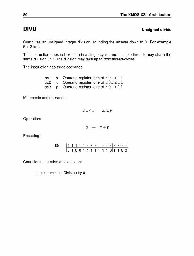
80 The XMOS XS1 Architecture
DIVU Unsigned divide
Computes an unsigned integer division, rounding the answer down to 0. For example5÷ 3 is 1.
This instruction does not execute in a single cycle, and multiple threads may share thesame division unit. The division may take up to bpw thread-cycles.
The instruction has three operands:
op1 d Operand register, one of r0...r11op2 x Operand register, one of r0...r11op3 y Operand register, one of r0...r11
Mnemonic and operands:
DIVU d , x , y
Operation:
d ← x ÷ y
Encoding:
1 1 1 1 1 . . . . . . . . . . .0 1 0 0 1 1 1 1 1 1 1 0 1 1 0 0
l3r
Conditions that raise an exception:
ET ARITHMETIC Division by 0.
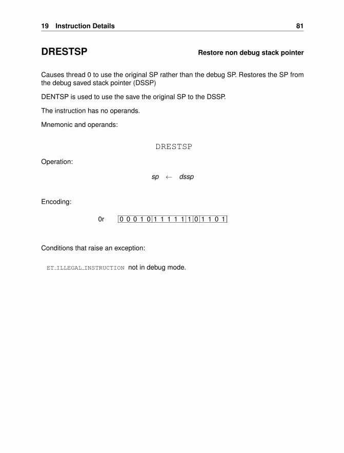
19 Instruction Details 81
DRESTSP Restore non debug stack pointer
Causes thread 0 to use the original SP rather than the debug SP. Restores the SP fromthe debug saved stack pointer (DSSP)
DENTSP is used to use the save the original SP to the DSSP.
The instruction has no operands.
Mnemonic and operands:
DRESTSP
Operation:
sp ← dssp
Encoding:
0 0 0 1 0 1 1 1 1 1 1 0 1 1 0 10r
Conditions that raise an exception:
ET ILLEGAL INSTRUCTION not in debug mode.
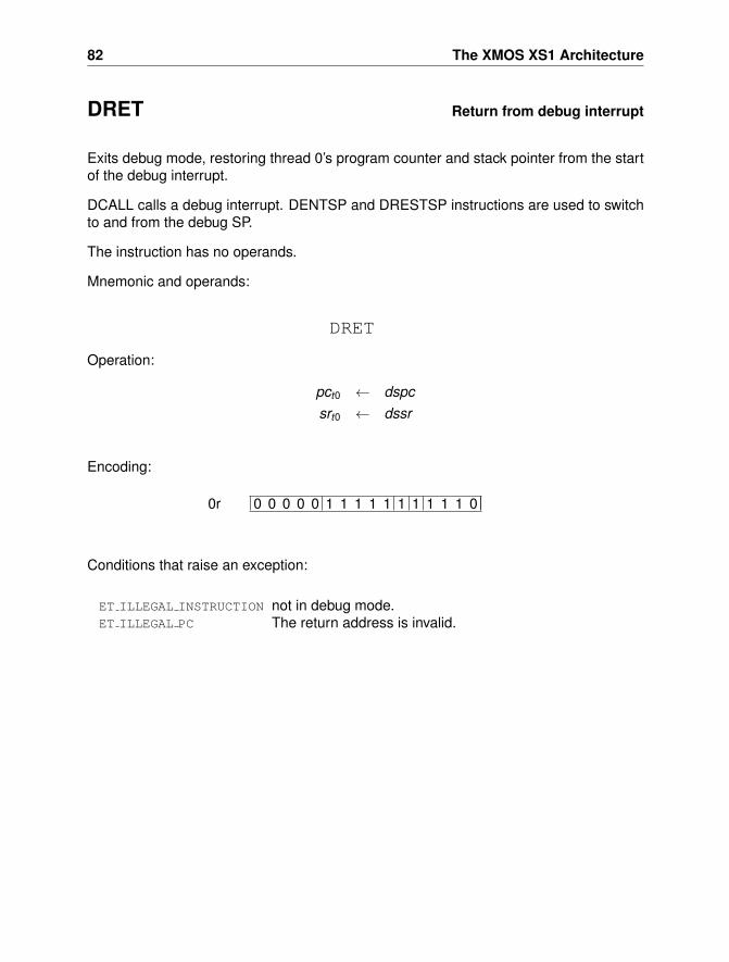
82 The XMOS XS1 Architecture
DRET Return from debug interrupt
Exits debug mode, restoring thread 0’s program counter and stack pointer from the startof the debug interrupt.
DCALL calls a debug interrupt. DENTSP and DRESTSP instructions are used to switchto and from the debug SP.
The instruction has no operands.
Mnemonic and operands:
DRET
Operation:
pct0 ← dspcsrt0 ← dssr
Encoding:
0 0 0 0 0 1 1 1 1 1 1 1 1 1 1 00r
Conditions that raise an exception:
ET ILLEGAL INSTRUCTION not in debug mode.ET ILLEGAL PC The return address is invalid.
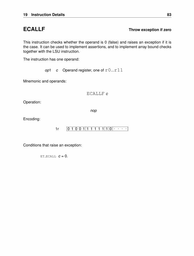
19 Instruction Details 83
ECALLF Throw exception if zero
This instruction checks whether the operand is 0 (false) and raises an exception if it isthe case. It can be used to implement assertions, and to implement array bound checkstogether with the LSU instruction.
The instruction has one operand:
op1 c Operand register, one of r0...r11
Mnemonic and operands:
ECALLF c
Operation:
nop
Encoding:
0 1 0 0 1 1 1 1 1 1 1 0 . . . .1r
Conditions that raise an exception:
ET ECALL c = 0.
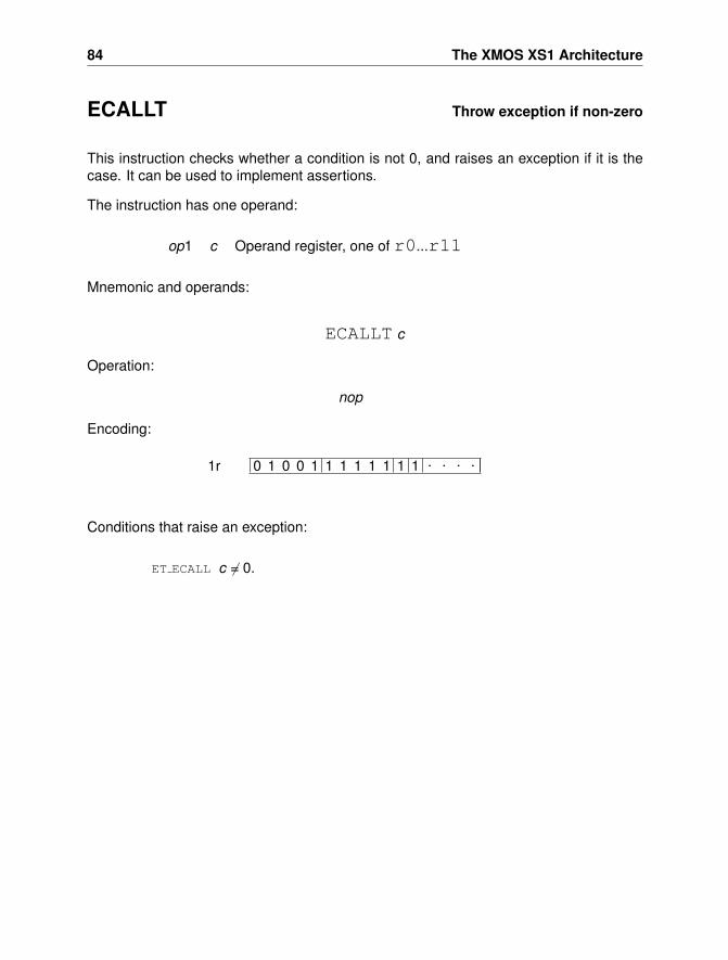
84 The XMOS XS1 Architecture
ECALLT Throw exception if non-zero
This instruction checks whether a condition is not 0, and raises an exception if it is thecase. It can be used to implement assertions.
The instruction has one operand:
op1 c Operand register, one of r0...r11
Mnemonic and operands:
ECALLT c
Operation:
nop
Encoding:
0 1 0 0 1 1 1 1 1 1 1 1 . . . .1r
Conditions that raise an exception:
ET ECALL c 6= 0.
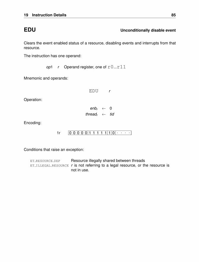
19 Instruction Details 85
EDU Unconditionally disable event
Clears the event enabled status of a resource, disabling events and interrupts from thatresource.
The instruction has one operand:
op1 r Operand register, one of r0...r11
Mnemonic and operands:
EDU r
Operation:
enbr ← 0threadr ← tid
Encoding:
0 0 0 0 0 1 1 1 1 1 1 0 . . . .1r
Conditions that raise an exception:
ET RESOURCE DEP Resource illegally shared between threadsET ILLEGAL RESOURCE r is not referring to a legal resource, or the resource is
not in use.
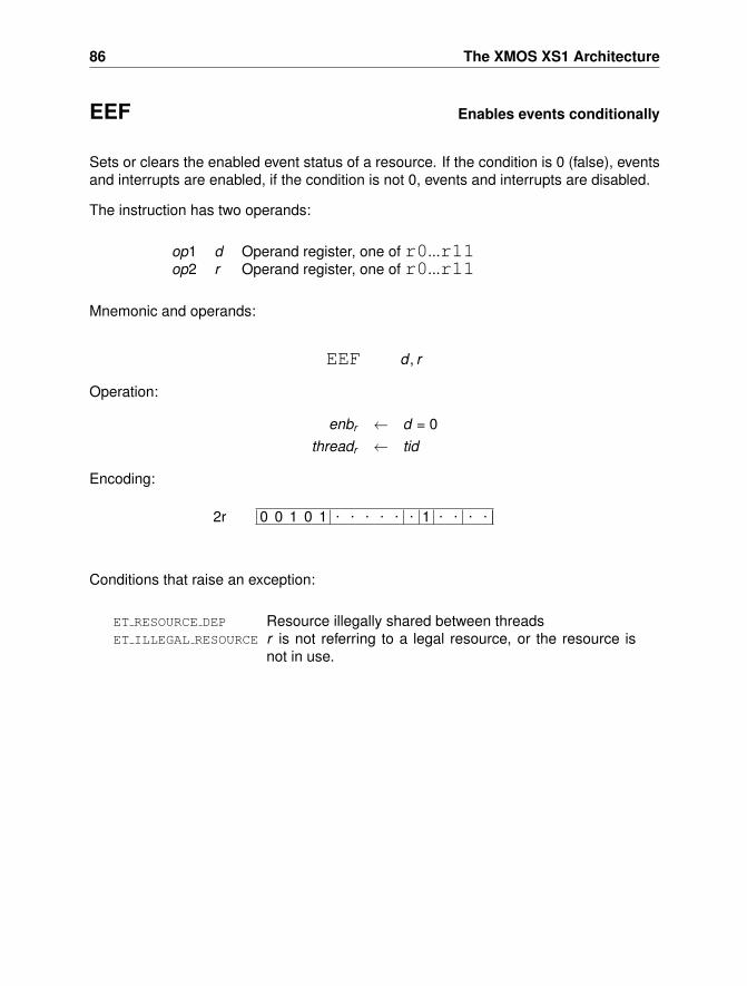
86 The XMOS XS1 Architecture
EEF Enables events conditionally
Sets or clears the enabled event status of a resource. If the condition is 0 (false), eventsand interrupts are enabled, if the condition is not 0, events and interrupts are disabled.
The instruction has two operands:
op1 d Operand register, one of r0...r11op2 r Operand register, one of r0...r11
Mnemonic and operands:
EEF d , r
Operation:
enbr ← d = 0threadr ← tid
Encoding:
0 0 1 0 1 . . . . . . 1 . . . .2r
Conditions that raise an exception:
ET RESOURCE DEP Resource illegally shared between threadsET ILLEGAL RESOURCE r is not referring to a legal resource, or the resource is
not in use.
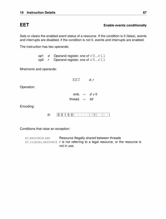
19 Instruction Details 87
EET Enable events conditionally
Sets or clears the enabled event status of a resource. If the condition is 0 (false), eventsand interrupts are disabled, if the condition is not 0, events and interrupts are enabled.
The instruction has two operands:
op1 d Operand register, one of r0...r11op2 r Operand register, one of r0...r11
Mnemonic and operands:
EET d , r
Operation:
enbr ← d 6= 0threadr ← tid
Encoding:
0 0 1 0 0 . . . . . . 1 . . . .2r
Conditions that raise an exception:
ET RESOURCE DEP Resource illegally shared between threadsET ILLEGAL RESOURCE r is not referring to a legal resource, or the resource is
not in use.
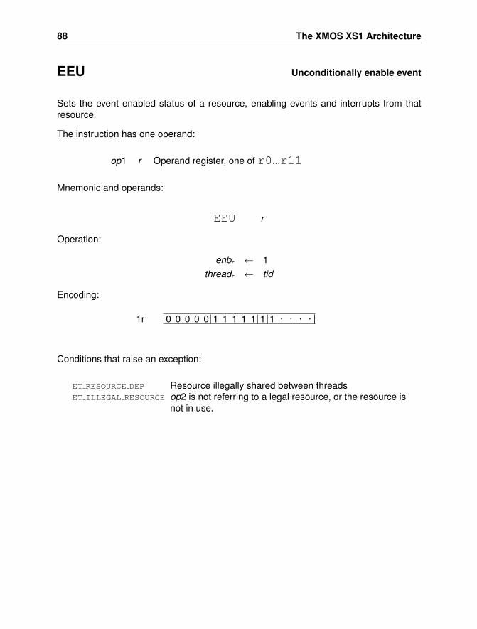
88 The XMOS XS1 Architecture
EEU Unconditionally enable event
Sets the event enabled status of a resource, enabling events and interrupts from thatresource.
The instruction has one operand:
op1 r Operand register, one of r0...r11
Mnemonic and operands:
EEU r
Operation:
enbr ← 1threadr ← tid
Encoding:
0 0 0 0 0 1 1 1 1 1 1 1 . . . .1r
Conditions that raise an exception:
ET RESOURCE DEP Resource illegally shared between threadsET ILLEGAL RESOURCE op2 is not referring to a legal resource, or the resource is
not in use.
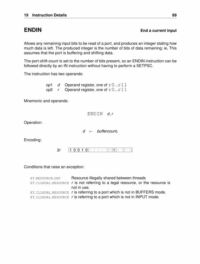
19 Instruction Details 89
ENDIN End a current input
Allows any remaining input bits to be read of a port, and produces an integer stating howmuch data is left. The produced integer is the number of bits of data remaining; ie, Thisassumes that the port is buffering and shifting data.
The port-shift-count is set to the number of bits present, so an ENDIN instruction can befollowed directly by an IN instruction without having to perform a SETPSC.
The instruction has two operands:
op1 d Operand register, one of r0...r11op2 r Operand register, one of r0...r11
Mnemonic and operands:
ENDIN d , r
Operation:
d ← buffercountr
Encoding:
1 0 0 1 0 . . . . . . 1 . . . .2r
Conditions that raise an exception:
ET RESOURCE DEP Resource illegally shared between threadsET ILLEGAL RESOURCE r is not referring to a legal resource, or the resource is
not in use.ET ILLEGAL RESOURCE r is referring to a port which is not in BUFFERS mode.ET ILLEGAL RESOURCE r is referring to a port which is not in INPUT mode.
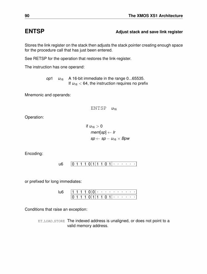
90 The XMOS XS1 Architecture
ENTSP Adjust stack and save link register
Stores the link register on the stack then adjusts the stack pointer creating enough spacefor the procedure call that has just been entered.
See RETSP for the operation that restores the link-register.
The instruction has one operand:
op1 u16 A 16-bit immediate in the range 0...65535.If u16 < 64, the instruction requires no prefix
Mnemonic and operands:
ENTSP u16
Operation:
if u16 > 0mem[sp]← lrsp ← sp − u16 × Bpw
Encoding:
0 1 1 1 0 1 1 1 0 1 . . . . . .u6
or prefixed for long immediates:
1 1 1 1 0 0 . . . . . . . . . .0 1 1 1 0 1 1 1 0 1 . . . . . .
lu6
Conditions that raise an exception:
ET LOAD STORE The indexed address is unaligned, or does not point to avalid memory address.
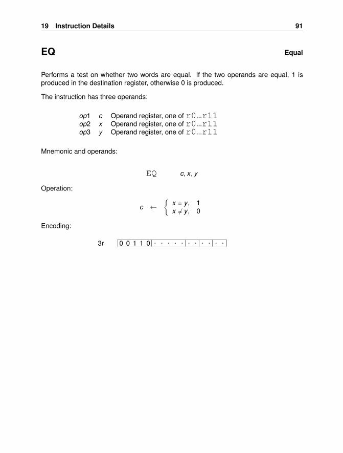
19 Instruction Details 91
EQ Equal
Performs a test on whether two words are equal. If the two operands are equal, 1 isproduced in the destination register, otherwise 0 is produced.
The instruction has three operands:
op1 c Operand register, one of r0...r11op2 x Operand register, one of r0...r11op3 y Operand register, one of r0...r11
Mnemonic and operands:
EQ c, x , y
Operation:
c ←{
x = y , 1x 6= y , 0
Encoding:
0 0 1 1 0 . . . . . . . . . . .3r
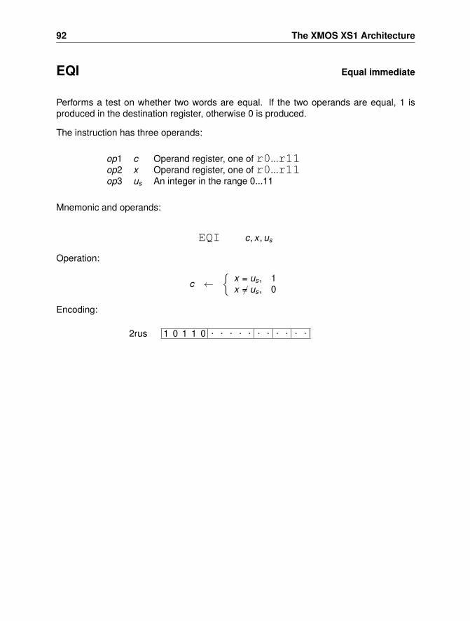
92 The XMOS XS1 Architecture
EQI Equal immediate
Performs a test on whether two words are equal. If the two operands are equal, 1 isproduced in the destination register, otherwise 0 is produced.
The instruction has three operands:
op1 c Operand register, one of r0...r11op2 x Operand register, one of r0...r11op3 us An integer in the range 0...11
Mnemonic and operands:
EQI c, x , us
Operation:
c ←{
x = us, 1x 6= us, 0
Encoding:
1 0 1 1 0 . . . . . . . . . . .2rus
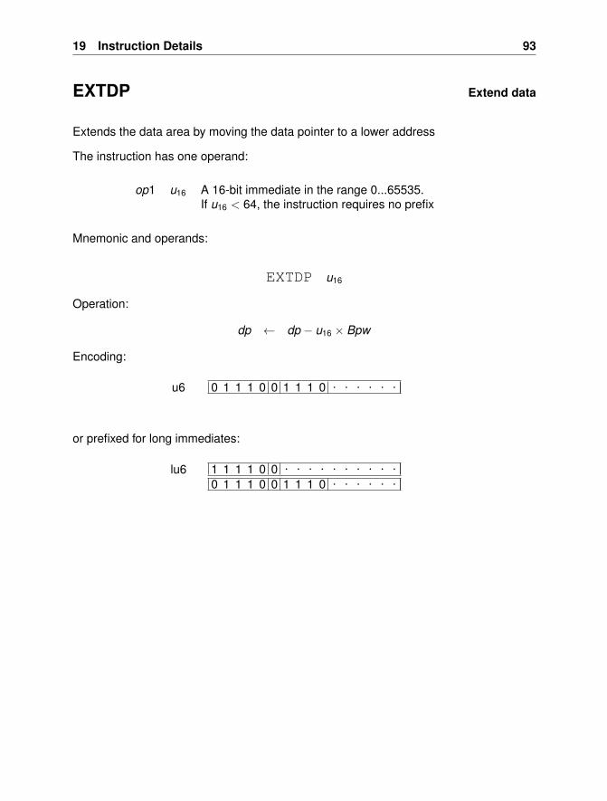
19 Instruction Details 93
EXTDP Extend data
Extends the data area by moving the data pointer to a lower address
The instruction has one operand:
op1 u16 A 16-bit immediate in the range 0...65535.If u16 < 64, the instruction requires no prefix
Mnemonic and operands:
EXTDP u16
Operation:
dp ← dp − u16 × Bpw
Encoding:
0 1 1 1 0 0 1 1 1 0 . . . . . .u6
or prefixed for long immediates:
1 1 1 1 0 0 . . . . . . . . . .0 1 1 1 0 0 1 1 1 0 . . . . . .
lu6
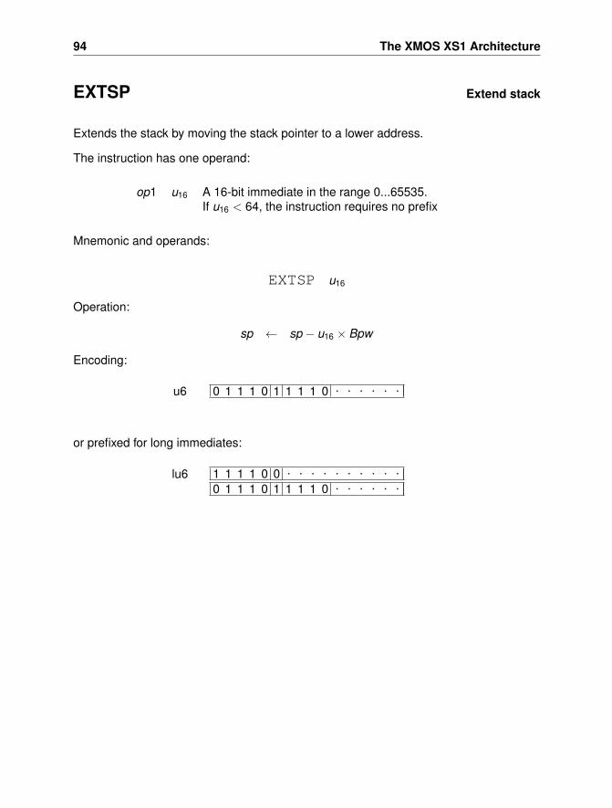
94 The XMOS XS1 Architecture
EXTSP Extend stack
Extends the stack by moving the stack pointer to a lower address.
The instruction has one operand:
op1 u16 A 16-bit immediate in the range 0...65535.If u16 < 64, the instruction requires no prefix
Mnemonic and operands:
EXTSP u16
Operation:
sp ← sp − u16 × Bpw
Encoding:
0 1 1 1 0 1 1 1 1 0 . . . . . .u6
or prefixed for long immediates:
1 1 1 1 0 0 . . . . . . . . . .0 1 1 1 0 1 1 1 1 0 . . . . . .
lu6
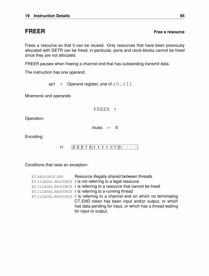
19 Instruction Details 95
FREER Free a resource
Frees a resource so that it can be reused. Only resources that have been previouslyallocated with GETR can be freed; in particular, ports and clock-blocks cannot be freedsince they are not allocated.
FREER pauses when freeing a channel end that has outstanding transmit data.
The instruction has one operand:
op1 r Operand register, one of r0...r11
Mnemonic and operands:
FREER r
Operation:
inuser ← 0
Encoding:
0 0 0 1 0 1 1 1 1 1 1 0 . . . .1r
Conditions that raise an exception:
ET RESOURCE DEP Resource illegally shared between threadsET ILLEGAL RESOURCE r is not referring to a legal resourceET ILLEGAL RESOURCE r is referring to a resource that cannot be freedET ILLEGAL RESOURCE r is referring to a running threadET ILLEGAL RESOURCE r is referring to a channel end on which no terminating
CT END token has been input and/or output, or whichhas data pending for input, or which has a thread waitingfor input or output.
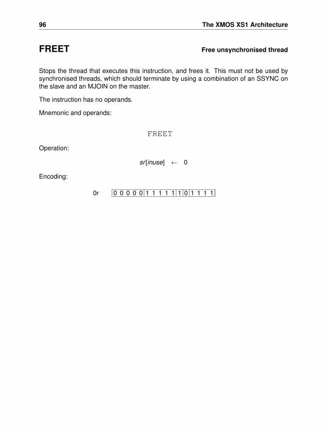
96 The XMOS XS1 Architecture
FREET Free unsynchronised thread
Stops the thread that executes this instruction, and frees it. This must not be used bysynchronised threads, which should terminate by using a combination of an SSYNC onthe slave and an MJOIN on the master.
The instruction has no operands.
Mnemonic and operands:
FREET
Operation:
sr [inuse] ← 0
Encoding:
0 0 0 0 0 1 1 1 1 1 1 0 1 1 1 10r
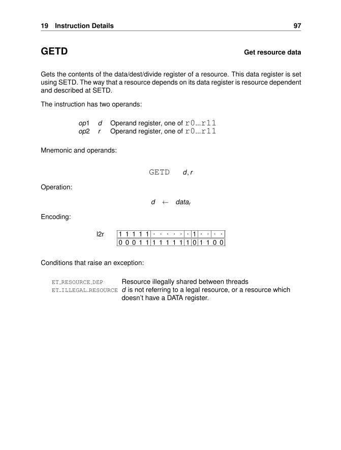
19 Instruction Details 97
GETD Get resource data
Gets the contents of the data/dest/divide register of a resource. This data register is setusing SETD. The way that a resource depends on its data register is resource dependentand described at SETD.
The instruction has two operands:
op1 d Operand register, one of r0...r11op2 r Operand register, one of r0...r11
Mnemonic and operands:
GETD d , r
Operation:
d ← datar
Encoding:
1 1 1 1 1 . . . . . . 1 . . . .0 0 0 1 1 1 1 1 1 1 1 0 1 1 0 0
l2r
Conditions that raise an exception:
ET RESOURCE DEP Resource illegally shared between threadsET ILLEGAL RESOURCE d is not referring to a legal resource, or a resource which
doesn’t have a DATA register.
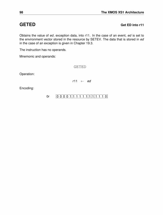
98 The XMOS XS1 Architecture
GETED Get ED into r11
Obtains the value of ed , exception data, into r11. In the case of an event, ed is set tothe environment vector stored in the resource by SETEV. The data that is stored in edin the case of an exception is given in Chapter 19.3.
The instruction has no operands.
Mnemonic and operands:
GETED
Operation:
r11 ← ed
Encoding:
0 0 0 0 1 1 1 1 1 1 1 1 1 1 1 00r
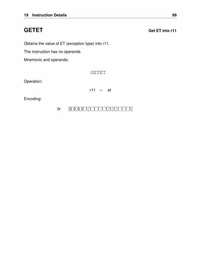
19 Instruction Details 99
GETET Get ET into r11
Obtains the value of ET (exception type) into r11.
The instruction has no operands.
Mnemonic and operands:
GETET
Operation:
r11 ← et
Encoding:
0 0 0 0 1 1 1 1 1 1 1 1 1 1 1 10r
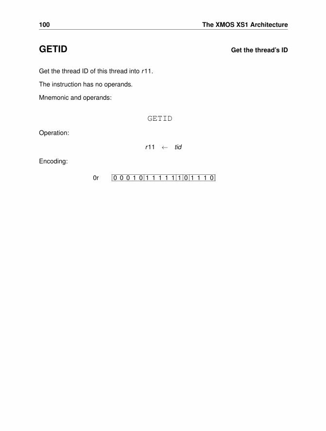
100 The XMOS XS1 Architecture
GETID Get the thread’s ID
Get the thread ID of this thread into r11.
The instruction has no operands.
Mnemonic and operands:
GETID
Operation:
r11 ← tid
Encoding:
0 0 0 1 0 1 1 1 1 1 1 0 1 1 1 00r
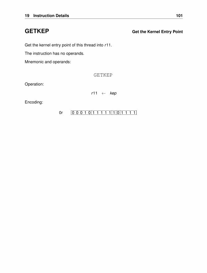
19 Instruction Details 101
GETKEP Get the Kernel Entry Point
Get the kernel entry point of this thread into r11.
The instruction has no operands.
Mnemonic and operands:
GETKEP
Operation:
r11 ← kep
Encoding:
0 0 0 1 0 1 1 1 1 1 1 0 1 1 1 10r
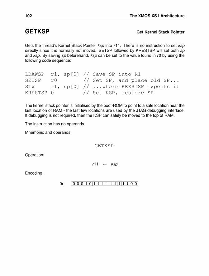
102 The XMOS XS1 Architecture
GETKSP Get Kernel Stack Pointer
Gets the thread’s Kernel Stack Pointer ksp into r11. There is no instruction to set kspdirectly since it is normally not moved. SETSP followed by KRESTSP will set both spand ksp. By saving sp beforehand, ksp can be set to the value found in r0 by using thefollowing code sequence:
LDAWSP r1, sp[0] // Save SP into R1SETSP r0 // Set SP, and place old SP...STW r1, sp[0] // ...where KRESTSP expects itKRESTSP 0 // Set KSP, restore SP
The kernel stack pointer is initialised by the boot-ROM to point to a safe location near thelast location of RAM - the last few locations are used by the JTAG debugging interface.If debugging is not required, then the KSP can safely be moved to the top of RAM.
The instruction has no operands.
Mnemonic and operands:
GETKSP
Operation:
r11 ← ksp
Encoding:
0 0 0 1 0 1 1 1 1 1 1 1 1 1 0 00r
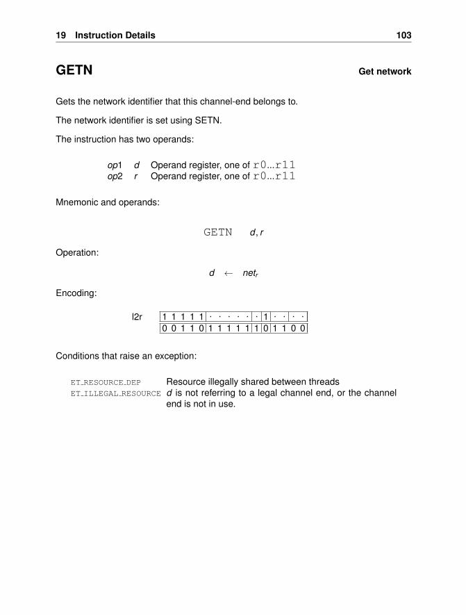
19 Instruction Details 103
GETN Get network
Gets the network identifier that this channel-end belongs to.
The network identifier is set using SETN.
The instruction has two operands:
op1 d Operand register, one of r0...r11op2 r Operand register, one of r0...r11
Mnemonic and operands:
GETN d , r
Operation:
d ← netr
Encoding:
1 1 1 1 1 . . . . . . 1 . . . .0 0 1 1 0 1 1 1 1 1 1 0 1 1 0 0
l2r
Conditions that raise an exception:
ET RESOURCE DEP Resource illegally shared between threadsET ILLEGAL RESOURCE d is not referring to a legal channel end, or the channel
end is not in use.
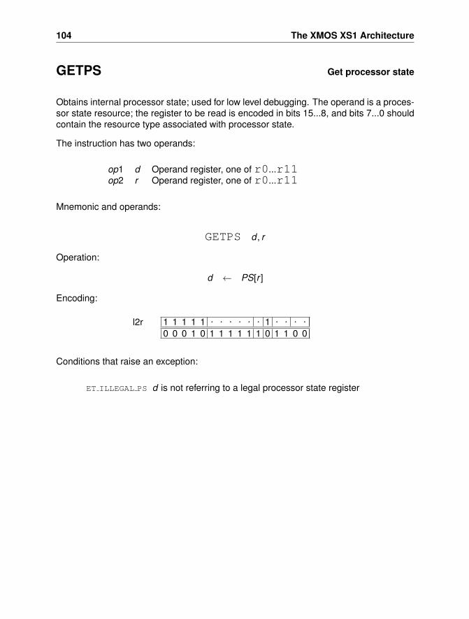
104 The XMOS XS1 Architecture
GETPS Get processor state
Obtains internal processor state; used for low level debugging. The operand is a proces-sor state resource; the register to be read is encoded in bits 15...8, and bits 7...0 shouldcontain the resource type associated with processor state.
The instruction has two operands:
op1 d Operand register, one of r0...r11op2 r Operand register, one of r0...r11
Mnemonic and operands:
GETPS d , r
Operation:
d ← PS[r ]
Encoding:
1 1 1 1 1 . . . . . . 1 . . . .0 0 0 1 0 1 1 1 1 1 1 0 1 1 0 0
l2r
Conditions that raise an exception:
ET ILLEGAL PS d is not referring to a legal processor state register
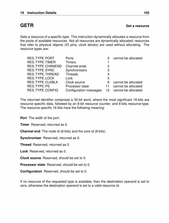
19 Instruction Details 105
GETR Get a resource
Gets a resource of a specific type. This instruction dynamically allocates a resource fromthe pools of available resources. Not all resources are dynamically allocated; resourcesthat refer to physical objects (IO pins, clock blocks) are used without allocating. Theresource types are:
RES TYPE PORT Ports 0 cannot be allocatedRES TYPE TIMER Timers 1RES TYPE CHANEND Channel ends 2RES TYPE SYNC Synchronisers 3RES TYPE THREAD Threads 4RES TYPE LOCK Lock 5RES TYPE CLKBLK Clock source 6 cannot be allocatedRES TYPE PS Processor state 11 cannot be allocatedRES TYPE CONFIG Configuration messages 12 cannot be allocated
The returned identifier comprises a 32-bit word, where the most significant 16-bits areresource specific data, followed by an 8-bit resource counter, and 8-bits resource-type.The resource specific 16 bits have the following meaning:
Port The width of the port.
Timer Reserved, returned as 0.
Channel end The node id (8-bits) and the core id (8-bits).
Synchroniser Reserved, returned as 0.
Thread Reserved, returned as 0.
Lock Reserved, returned as 0.
Clock source Reserved, should be set to 0.
Processor state Reserved, should be set to 0.
Configuration Reserved, should be set to 0.
If no resource of the requested type is available, then the destination operand is set tozero, otherwise the destination operand is set to a valid resource id.
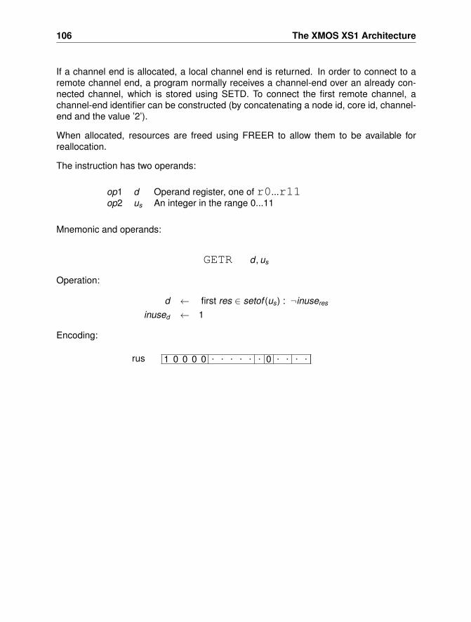
106 The XMOS XS1 Architecture
If a channel end is allocated, a local channel end is returned. In order to connect to aremote channel end, a program normally receives a channel-end over an already con-nected channel, which is stored using SETD. To connect the first remote channel, achannel-end identifier can be constructed (by concatenating a node id, core id, channel-end and the value ’2’).
When allocated, resources are freed using FREER to allow them to be available forreallocation.
The instruction has two operands:
op1 d Operand register, one of r0...r11op2 us An integer in the range 0...11
Mnemonic and operands:
GETR d , us
Operation:
d ← first res ∈ setof (us) : ¬inuseres
inused ← 1
Encoding:
1 0 0 0 0 . . . . . . 0 . . . .rus
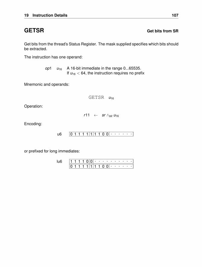
19 Instruction Details 107
GETSR Get bits from SR
Get bits from the thread’s Status Register. The mask supplied specifies which bits shouldbe extracted.
The instruction has one operand:
op1 u16 A 16-bit immediate in the range 0...65535.If u16 < 64, the instruction requires no prefix
Mnemonic and operands:
GETSR u16
Operation:
r11 ← sr ∧bit u16
Encoding:
0 1 1 1 1 1 1 1 0 0 . . . . . .u6
or prefixed for long immediates:
1 1 1 1 0 0 . . . . . . . . . .0 1 1 1 1 1 1 1 0 0 . . . . . .
lu6
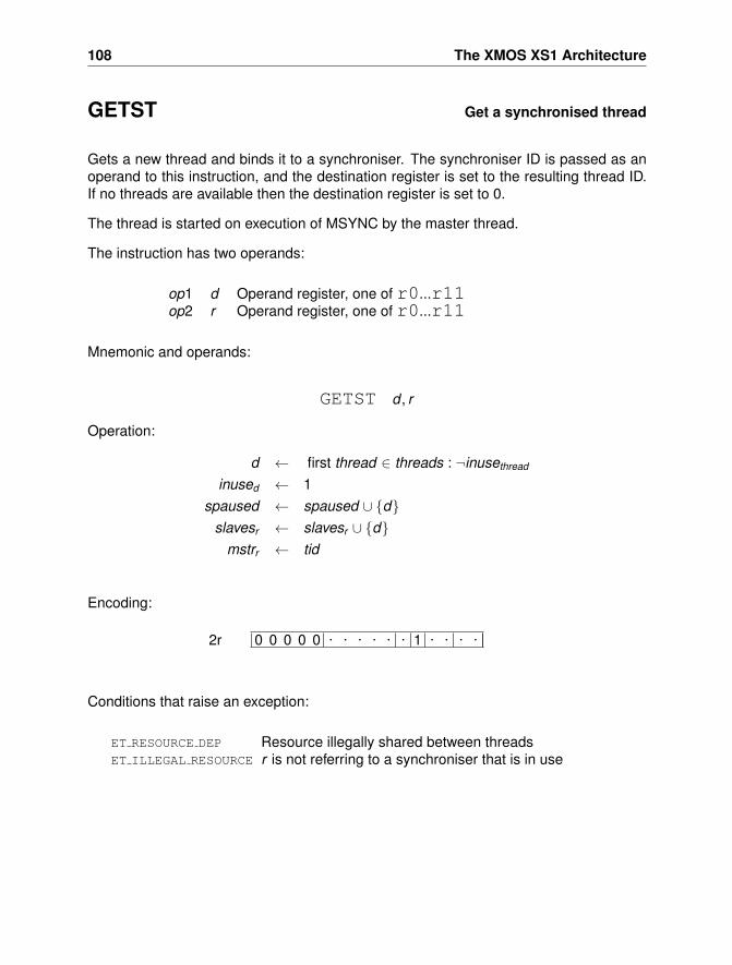
108 The XMOS XS1 Architecture
GETST Get a synchronised thread
Gets a new thread and binds it to a synchroniser. The synchroniser ID is passed as anoperand to this instruction, and the destination register is set to the resulting thread ID.If no threads are available then the destination register is set to 0.
The thread is started on execution of MSYNC by the master thread.
The instruction has two operands:
op1 d Operand register, one of r0...r11op2 r Operand register, one of r0...r11
Mnemonic and operands:
GETST d , r
Operation:
d ← first thread ∈ threads : ¬inusethread
inused ← 1spaused ← spaused ∪ {d}
slavesr ← slavesr ∪ {d}mstrr ← tid
Encoding:
0 0 0 0 0 . . . . . . 1 . . . .2r
Conditions that raise an exception:
ET RESOURCE DEP Resource illegally shared between threadsET ILLEGAL RESOURCE r is not referring to a synchroniser that is in use
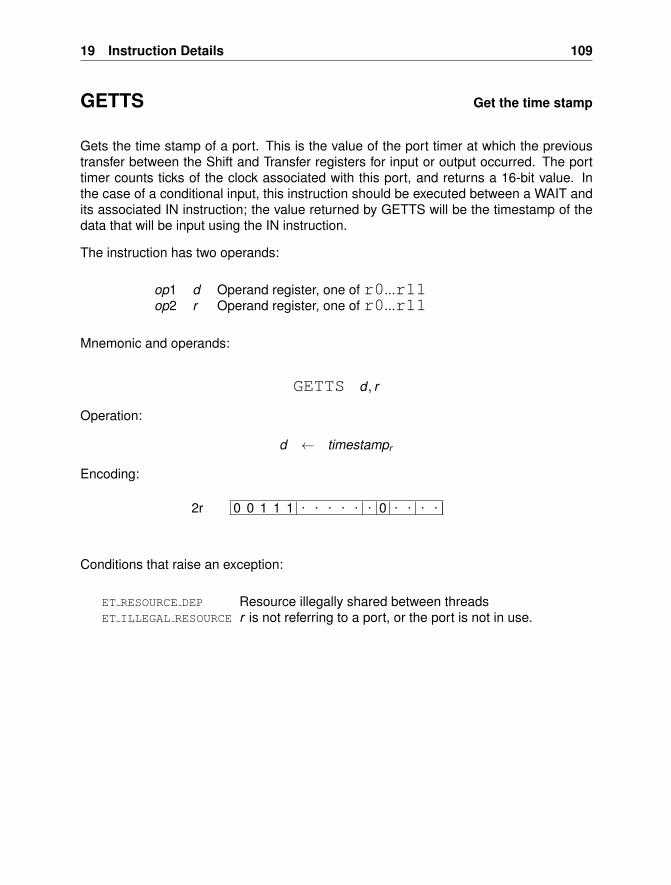
19 Instruction Details 109
GETTS Get the time stamp
Gets the time stamp of a port. This is the value of the port timer at which the previoustransfer between the Shift and Transfer registers for input or output occurred. The porttimer counts ticks of the clock associated with this port, and returns a 16-bit value. Inthe case of a conditional input, this instruction should be executed between a WAIT andits associated IN instruction; the value returned by GETTS will be the timestamp of thedata that will be input using the IN instruction.
The instruction has two operands:
op1 d Operand register, one of r0...r11op2 r Operand register, one of r0...r11
Mnemonic and operands:
GETTS d , r
Operation:
d ← timestampr
Encoding:
0 0 1 1 1 . . . . . . 0 . . . .2r
Conditions that raise an exception:
ET RESOURCE DEP Resource illegally shared between threadsET ILLEGAL RESOURCE r is not referring to a port, or the port is not in use.
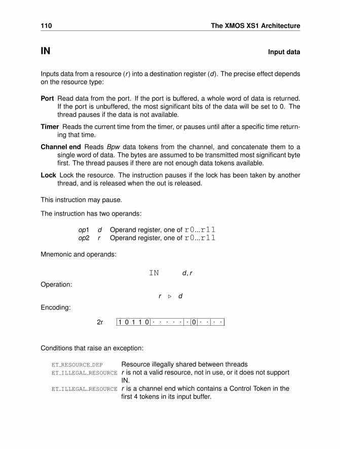
110 The XMOS XS1 Architecture
IN Input data
Inputs data from a resource (r ) into a destination register (d). The precise effect dependson the resource type:
Port Read data from the port. If the port is buffered, a whole word of data is returned.If the port is unbuffered, the most significant bits of the data will be set to 0. Thethread pauses if the data is not available.
Timer Reads the current time from the timer, or pauses until after a specific time return-ing that time.
Channel end Reads Bpw data tokens from the channel, and concatenate them to asingle word of data. The bytes are assumed to be transmitted most significant bytefirst. The thread pauses if there are not enough data tokens available.
Lock Lock the resource. The instruction pauses if the lock has been taken by anotherthread, and is released when the out is released.
This instruction may pause.
The instruction has two operands:
op1 d Operand register, one of r0...r11op2 r Operand register, one of r0...r11
Mnemonic and operands:
IN d , r
Operation:
r . d
Encoding:
1 0 1 1 0 . . . . . . 0 . . . .2r
Conditions that raise an exception:
ET RESOURCE DEP Resource illegally shared between threadsET ILLEGAL RESOURCE r is not a valid resource, not in use, or it does not support
IN.ET ILLEGAL RESOURCE r is a channel end which contains a Control Token in the
first 4 tokens in its input buffer.
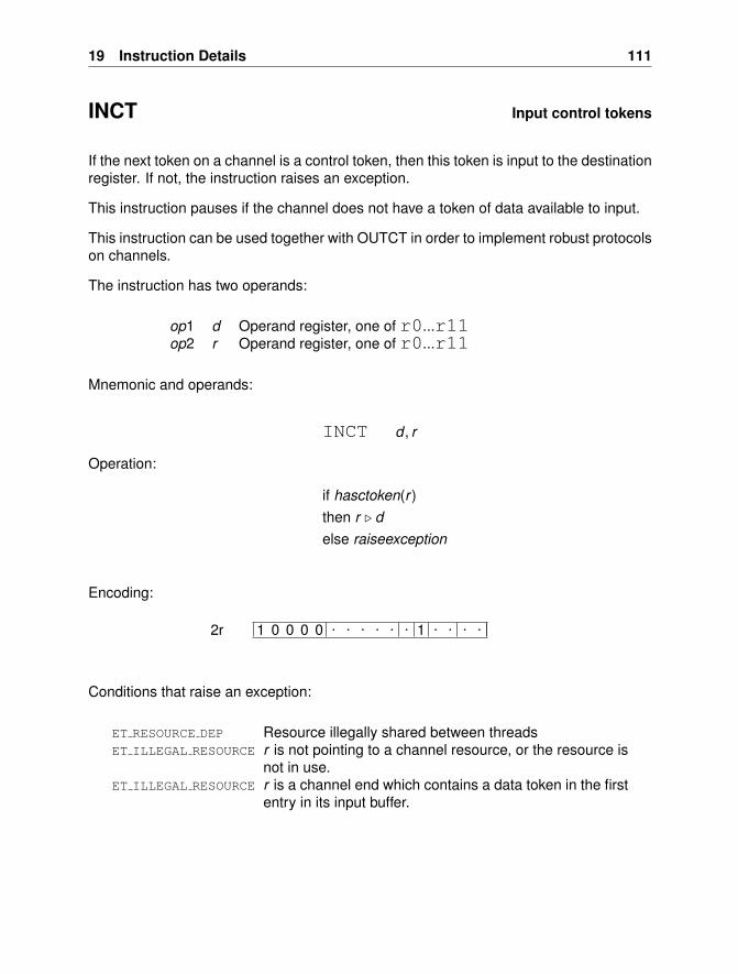
19 Instruction Details 111
INCT Input control tokens
If the next token on a channel is a control token, then this token is input to the destinationregister. If not, the instruction raises an exception.
This instruction pauses if the channel does not have a token of data available to input.
This instruction can be used together with OUTCT in order to implement robust protocolson channels.
The instruction has two operands:
op1 d Operand register, one of r0...r11op2 r Operand register, one of r0...r11
Mnemonic and operands:
INCT d , r
Operation:
if hasctoken(r )then r . delse raiseexception
Encoding:
1 0 0 0 0 . . . . . . 1 . . . .2r
Conditions that raise an exception:
ET RESOURCE DEP Resource illegally shared between threadsET ILLEGAL RESOURCE r is not pointing to a channel resource, or the resource is
not in use.ET ILLEGAL RESOURCE r is a channel end which contains a data token in the first
entry in its input buffer.
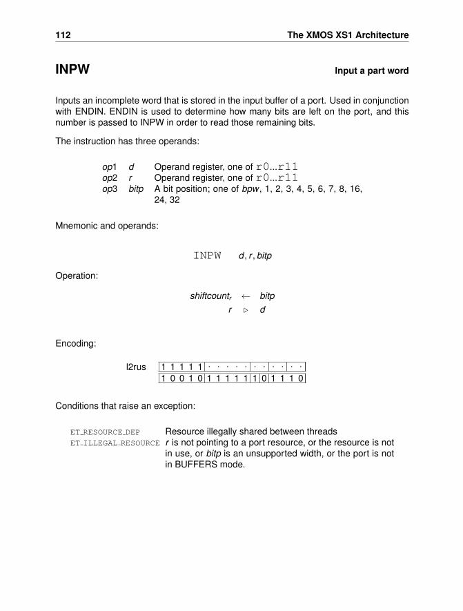
112 The XMOS XS1 Architecture
INPW Input a part word
Inputs an incomplete word that is stored in the input buffer of a port. Used in conjunctionwith ENDIN. ENDIN is used to determine how many bits are left on the port, and thisnumber is passed to INPW in order to read those remaining bits.
The instruction has three operands:
op1 d Operand register, one of r0...r11op2 r Operand register, one of r0...r11op3 bitp A bit position; one of bpw , 1, 2, 3, 4, 5, 6, 7, 8, 16,
24, 32
Mnemonic and operands:
INPW d , r , bitp
Operation:
shiftcountr ← bitpr . d
Encoding:
1 1 1 1 1 . . . . . . . . . . .
1 0 0 1 0 1 1 1 1 1 1 0 1 1 1 0l2rus
Conditions that raise an exception:
ET RESOURCE DEP Resource illegally shared between threadsET ILLEGAL RESOURCE r is not pointing to a port resource, or the resource is not
in use, or bitp is an unsupported width, or the port is notin BUFFERS mode.
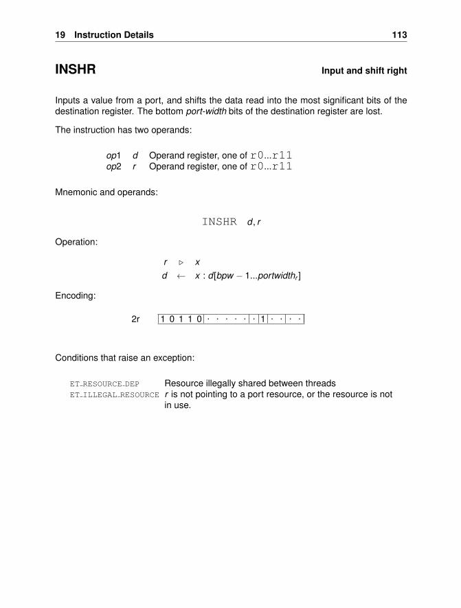
19 Instruction Details 113
INSHR Input and shift right
Inputs a value from a port, and shifts the data read into the most significant bits of thedestination register. The bottom port-width bits of the destination register are lost.
The instruction has two operands:
op1 d Operand register, one of r0...r11op2 r Operand register, one of r0...r11
Mnemonic and operands:
INSHR d , r
Operation:
r . xd ← x : d [bpw − 1...portwidthr ]
Encoding:
1 0 1 1 0 . . . . . . 1 . . . .2r
Conditions that raise an exception:
ET RESOURCE DEP Resource illegally shared between threadsET ILLEGAL RESOURCE r is not pointing to a port resource, or the resource is not
in use.
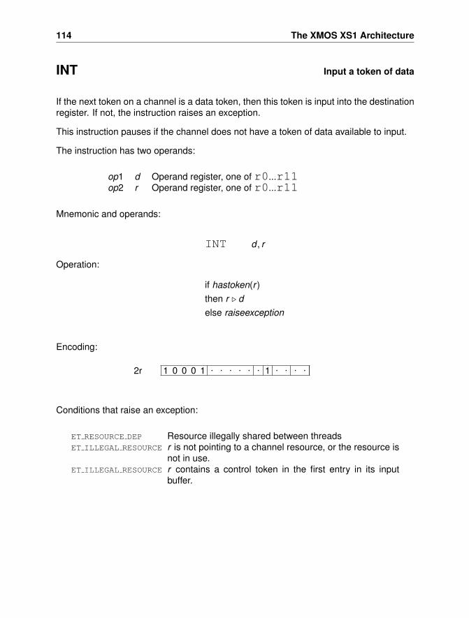
114 The XMOS XS1 Architecture
INT Input a token of data
If the next token on a channel is a data token, then this token is input into the destinationregister. If not, the instruction raises an exception.
This instruction pauses if the channel does not have a token of data available to input.
The instruction has two operands:
op1 d Operand register, one of r0...r11op2 r Operand register, one of r0...r11
Mnemonic and operands:
INT d , r
Operation:
if hastoken(r )then r . delse raiseexception
Encoding:
1 0 0 0 1 . . . . . . 1 . . . .2r
Conditions that raise an exception:
ET RESOURCE DEP Resource illegally shared between threadsET ILLEGAL RESOURCE r is not pointing to a channel resource, or the resource is
not in use.ET ILLEGAL RESOURCE r contains a control token in the first entry in its input
buffer.
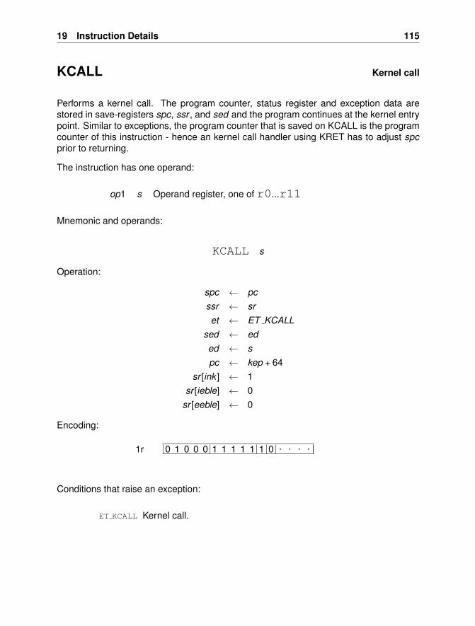
19 Instruction Details 115
KCALL Kernel call
Performs a kernel call. The program counter, status register and exception data arestored in save-registers spc, ssr , and sed and the program continues at the kernel entrypoint. Similar to exceptions, the program counter that is saved on KCALL is the programcounter of this instruction - hence an kernel call handler using KRET has to adjust spcprior to returning.
The instruction has one operand:
op1 s Operand register, one of r0...r11
Mnemonic and operands:
KCALL s
Operation:
spc ← pcssr ← sret ← ET KCALL
sed ← eded ← spc ← kep + 64
sr [ink ] ← 1sr [ieble] ← 0
sr [eeble] ← 0
Encoding:
0 1 0 0 0 1 1 1 1 1 1 0 . . . .1r
Conditions that raise an exception:
ET KCALL Kernel call.
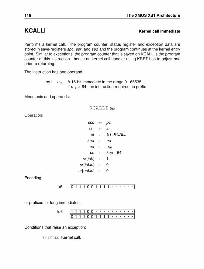
116 The XMOS XS1 Architecture
KCALLI Kernel call immediate
Performs a kernel call. The program counter, status register and exception data arestored in save-registers spc, ssr , and sed and the program continues at the kernel entrypoint. Similar to exceptions, the program counter that is saved on KCALL is the programcounter of this instruction - hence an kernel call handler using KRET has to adjust spcprior to returning.
The instruction has one operand:
op1 u16 A 16-bit immediate in the range 0...65535.If u16 < 64, the instruction requires no prefix
Mnemonic and operands:
KCALLI u16
Operation:
spc ← pcssr ← sret ← ET KCALL
sed ← eded ← u16
pc ← kep + 64sr [ink ] ← 1
sr [ieble] ← 0sr [eeble] ← 0
Encoding:
0 1 1 1 0 0 1 1 1 1 . . . . . .u6
or prefixed for long immediates:
1 1 1 1 0 0 . . . . . . . . . .0 1 1 1 0 0 1 1 1 1 . . . . . .
lu6
Conditions that raise an exception:
ET KCALL Kernel call.
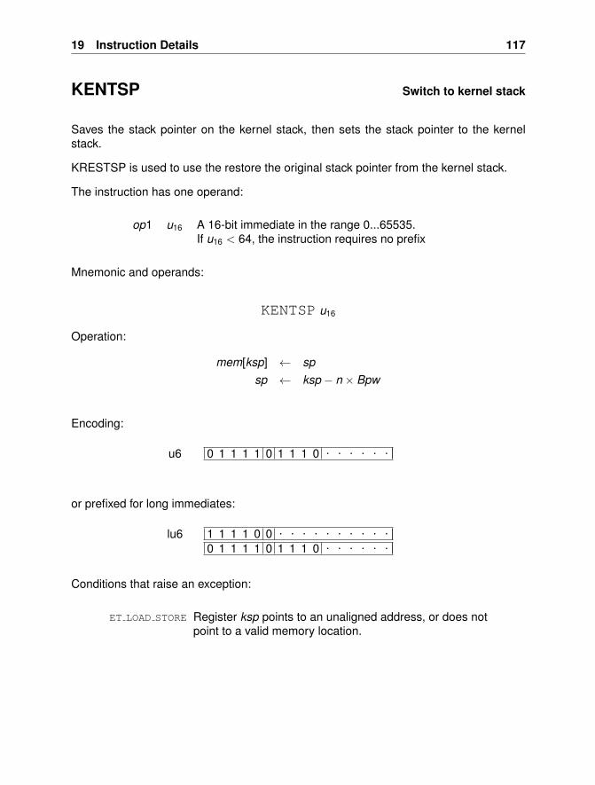
19 Instruction Details 117
KENTSP Switch to kernel stack
Saves the stack pointer on the kernel stack, then sets the stack pointer to the kernelstack.
KRESTSP is used to use the restore the original stack pointer from the kernel stack.
The instruction has one operand:
op1 u16 A 16-bit immediate in the range 0...65535.If u16 < 64, the instruction requires no prefix
Mnemonic and operands:
KENTSP u16
Operation:
mem[ksp] ← spsp ← ksp − n × Bpw
Encoding:
0 1 1 1 1 0 1 1 1 0 . . . . . .u6
or prefixed for long immediates:
1 1 1 1 0 0 . . . . . . . . . .0 1 1 1 1 0 1 1 1 0 . . . . . .
lu6
Conditions that raise an exception:
ET LOAD STORE Register ksp points to an unaligned address, or does notpoint to a valid memory location.
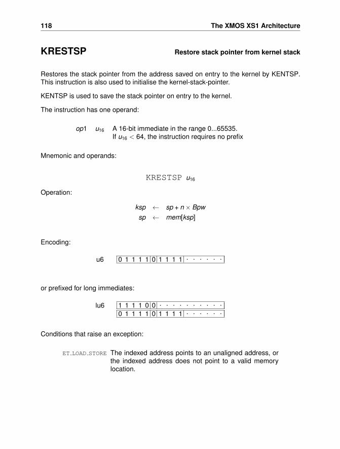
118 The XMOS XS1 Architecture
KRESTSP Restore stack pointer from kernel stack
Restores the stack pointer from the address saved on entry to the kernel by KENTSP.This instruction is also used to initialise the kernel-stack-pointer.
KENTSP is used to save the stack pointer on entry to the kernel.
The instruction has one operand:
op1 u16 A 16-bit immediate in the range 0...65535.If u16 < 64, the instruction requires no prefix
Mnemonic and operands:
KRESTSP u16
Operation:
ksp ← sp + n × Bpwsp ← mem[ksp]
Encoding:
0 1 1 1 1 0 1 1 1 1 . . . . . .u6
or prefixed for long immediates:
1 1 1 1 0 0 . . . . . . . . . .0 1 1 1 1 0 1 1 1 1 . . . . . .
lu6
Conditions that raise an exception:
ET LOAD STORE The indexed address points to an unaligned address, orthe indexed address does not point to a valid memorylocation.
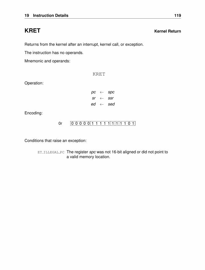
19 Instruction Details 119
KRET Kernel Return
Returns from the kernel after an interrupt, kernel call, or exception.
The instruction has no operands.
Mnemonic and operands:
KRET
Operation:
pc ← spcsr ← ssred ← sed
Encoding:
0 0 0 0 0 1 1 1 1 1 1 1 1 1 0 10r
Conditions that raise an exception:
ET ILLEGAL PC The register spc was not 16-bit aligned or did not point toa valid memory location.
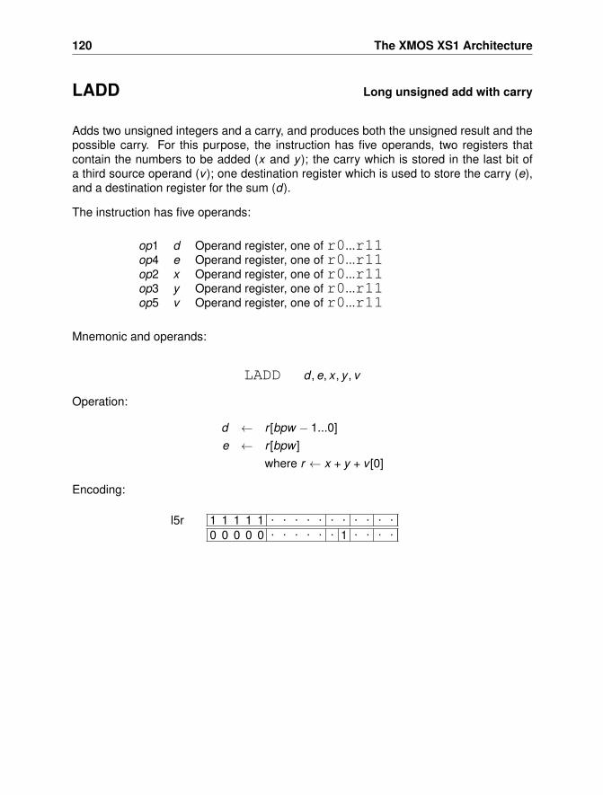
120 The XMOS XS1 Architecture
LADD Long unsigned add with carry
Adds two unsigned integers and a carry, and produces both the unsigned result and thepossible carry. For this purpose, the instruction has five operands, two registers thatcontain the numbers to be added (x and y ); the carry which is stored in the last bit ofa third source operand (v ); one destination register which is used to store the carry (e),and a destination register for the sum (d).
The instruction has five operands:
op1 d Operand register, one of r0...r11op4 e Operand register, one of r0...r11op2 x Operand register, one of r0...r11op3 y Operand register, one of r0...r11op5 v Operand register, one of r0...r11
Mnemonic and operands:
LADD d , e, x , y , v
Operation:
d ← r [bpw − 1...0]e ← r [bpw ]
where r ← x + y + v [0]
Encoding:
1 1 1 1 1 . . . . . . . . . . .0 0 0 0 0 . . . . . . 1 . . . .
l5r
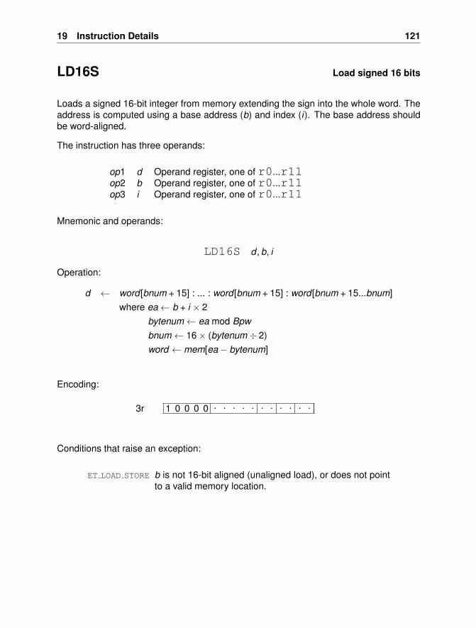
19 Instruction Details 121
LD16S Load signed 16 bits
Loads a signed 16-bit integer from memory extending the sign into the whole word. Theaddress is computed using a base address (b) and index (i). The base address shouldbe word-aligned.
The instruction has three operands:
op1 d Operand register, one of r0...r11op2 b Operand register, one of r0...r11op3 i Operand register, one of r0...r11
Mnemonic and operands:
LD16S d , b, i
Operation:
d ← word [bnum + 15] : ... : word [bnum + 15] : word [bnum + 15...bnum]where ea← b + i × 2
bytenum← ea mod Bpwbnum← 16× (bytenum ÷ 2)word ← mem[ea− bytenum]
Encoding:
1 0 0 0 0 . . . . . . . . . . .3r
Conditions that raise an exception:
ET LOAD STORE b is not 16-bit aligned (unaligned load), or does not pointto a valid memory location.
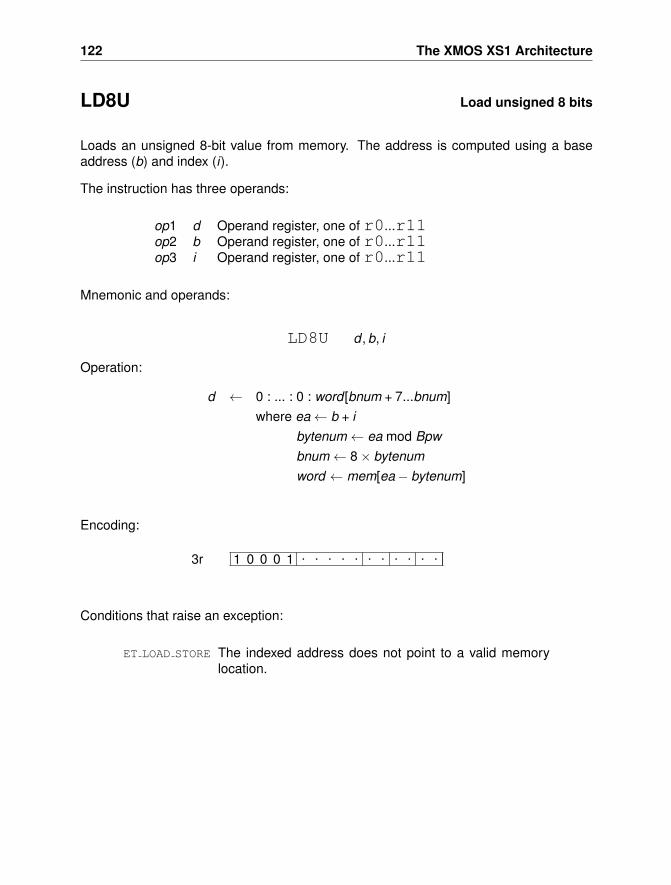
122 The XMOS XS1 Architecture
LD8U Load unsigned 8 bits
Loads an unsigned 8-bit value from memory. The address is computed using a baseaddress (b) and index (i).
The instruction has three operands:
op1 d Operand register, one of r0...r11op2 b Operand register, one of r0...r11op3 i Operand register, one of r0...r11
Mnemonic and operands:
LD8U d , b, i
Operation:
d ← 0 : ... : 0 : word [bnum + 7...bnum]where ea← b + i
bytenum← ea mod Bpwbnum← 8× bytenumword ← mem[ea− bytenum]
Encoding:
1 0 0 0 1 . . . . . . . . . . .3r
Conditions that raise an exception:
ET LOAD STORE The indexed address does not point to a valid memorylocation.
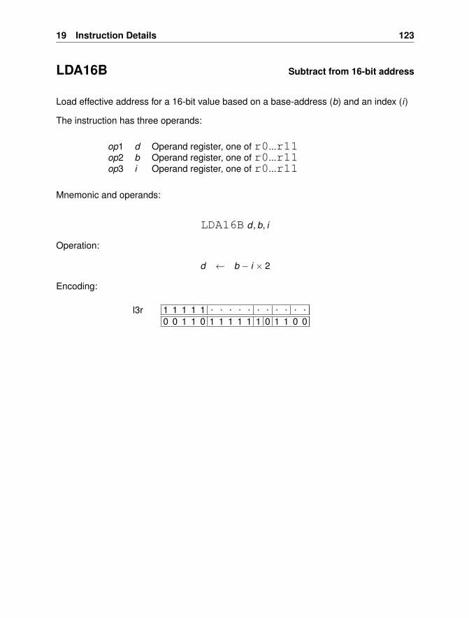
19 Instruction Details 123
LDA16B Subtract from 16-bit address
Load effective address for a 16-bit value based on a base-address (b) and an index (i)
The instruction has three operands:
op1 d Operand register, one of r0...r11op2 b Operand register, one of r0...r11op3 i Operand register, one of r0...r11
Mnemonic and operands:
LDA16B d , b, i
Operation:
d ← b − i × 2
Encoding:
1 1 1 1 1 . . . . . . . . . . .0 0 1 1 0 1 1 1 1 1 1 0 1 1 0 0
l3r
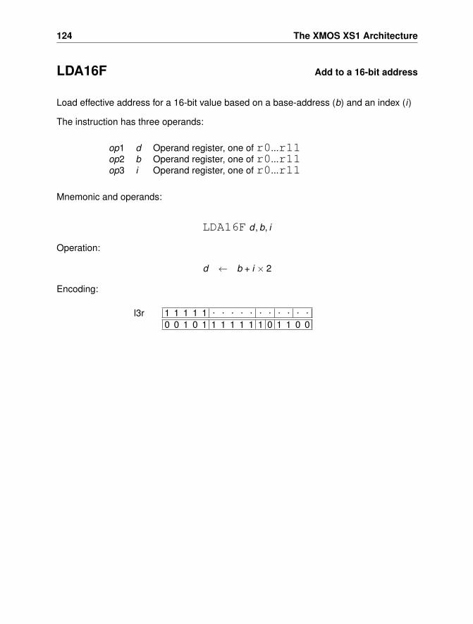
124 The XMOS XS1 Architecture
LDA16F Add to a 16-bit address
Load effective address for a 16-bit value based on a base-address (b) and an index (i)
The instruction has three operands:
op1 d Operand register, one of r0...r11op2 b Operand register, one of r0...r11op3 i Operand register, one of r0...r11
Mnemonic and operands:
LDA16F d , b, i
Operation:
d ← b + i × 2
Encoding:
1 1 1 1 1 . . . . . . . . . . .0 0 1 0 1 1 1 1 1 1 1 0 1 1 0 0
l3r
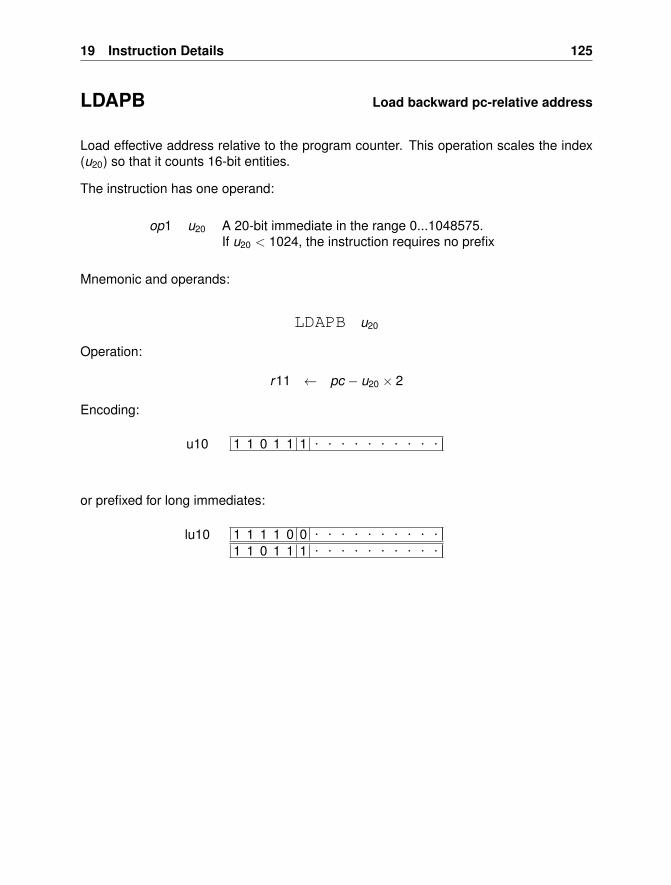
19 Instruction Details 125
LDAPB Load backward pc-relative address
Load effective address relative to the program counter. This operation scales the index(u20) so that it counts 16-bit entities.
The instruction has one operand:
op1 u20 A 20-bit immediate in the range 0...1048575.If u20 < 1024, the instruction requires no prefix
Mnemonic and operands:
LDAPB u20
Operation:
r11 ← pc − u20 × 2
Encoding:
1 1 0 1 1 1 . . . . . . . . . .u10
or prefixed for long immediates:
1 1 1 1 0 0 . . . . . . . . . .
1 1 0 1 1 1 . . . . . . . . . .lu10
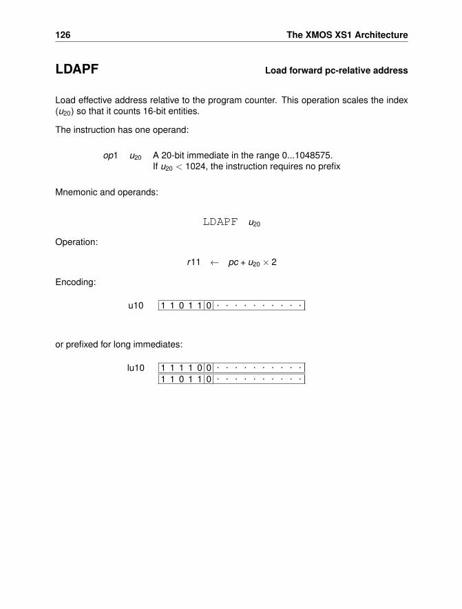
126 The XMOS XS1 Architecture
LDAPF Load forward pc-relative address
Load effective address relative to the program counter. This operation scales the index(u20) so that it counts 16-bit entities.
The instruction has one operand:
op1 u20 A 20-bit immediate in the range 0...1048575.If u20 < 1024, the instruction requires no prefix
Mnemonic and operands:
LDAPF u20
Operation:
r11 ← pc + u20 × 2
Encoding:
1 1 0 1 1 0 . . . . . . . . . .u10
or prefixed for long immediates:
1 1 1 1 0 0 . . . . . . . . . .
1 1 0 1 1 0 . . . . . . . . . .lu10
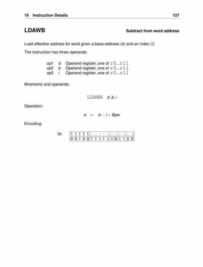
19 Instruction Details 127
LDAWB Subtract from word address
Load effective address for word given a base-address (b) and an index (i)
The instruction has three operands:
op1 d Operand register, one of r0...r11op2 b Operand register, one of r0...r11op3 i Operand register, one of r0...r11
Mnemonic and operands:
LDAWB d , b, i
Operation:
d ← b − i × Bpw
Encoding:
1 1 1 1 1 . . . . . . . . . . .0 0 1 0 0 1 1 1 1 1 1 0 1 1 0 0
l3r
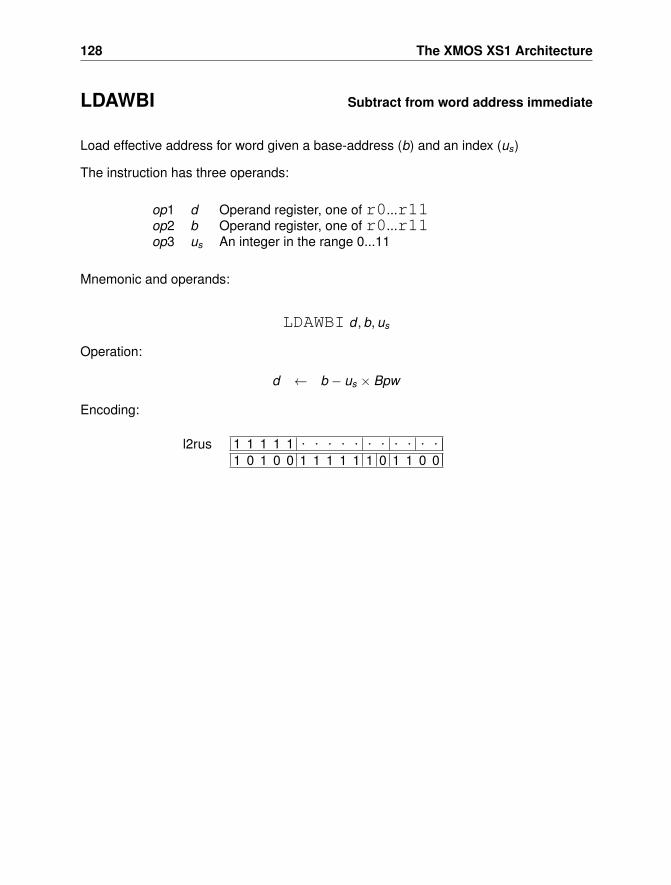
128 The XMOS XS1 Architecture
LDAWBI Subtract from word address immediate
Load effective address for word given a base-address (b) and an index (us)
The instruction has three operands:
op1 d Operand register, one of r0...r11op2 b Operand register, one of r0...r11op3 us An integer in the range 0...11
Mnemonic and operands:
LDAWBI d , b, us
Operation:
d ← b − us × Bpw
Encoding:
1 1 1 1 1 . . . . . . . . . . .
1 0 1 0 0 1 1 1 1 1 1 0 1 1 0 0l2rus
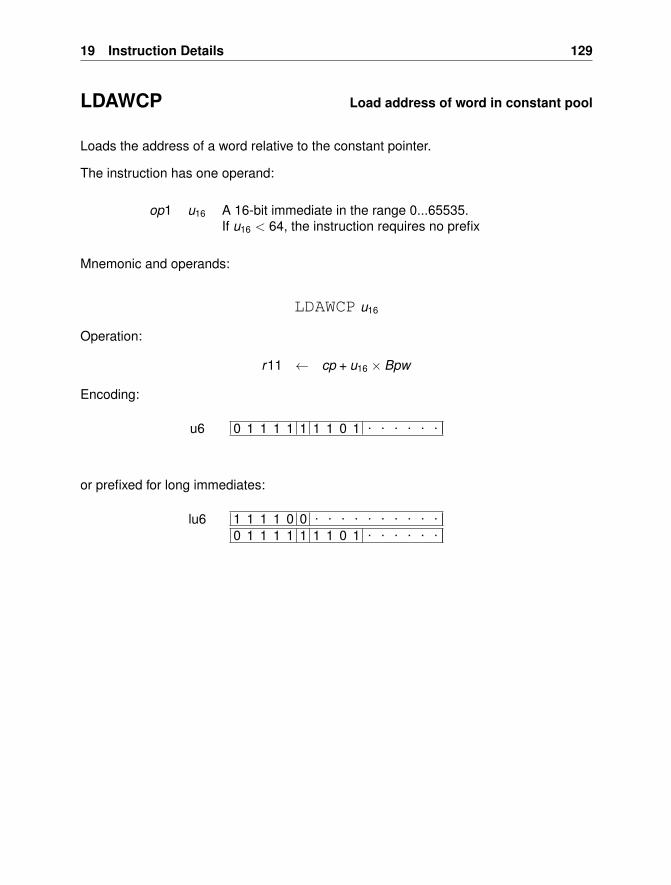
19 Instruction Details 129
LDAWCP Load address of word in constant pool
Loads the address of a word relative to the constant pointer.
The instruction has one operand:
op1 u16 A 16-bit immediate in the range 0...65535.If u16 < 64, the instruction requires no prefix
Mnemonic and operands:
LDAWCP u16
Operation:
r11 ← cp + u16 × Bpw
Encoding:
0 1 1 1 1 1 1 1 0 1 . . . . . .u6
or prefixed for long immediates:
1 1 1 1 0 0 . . . . . . . . . .0 1 1 1 1 1 1 1 0 1 . . . . . .
lu6
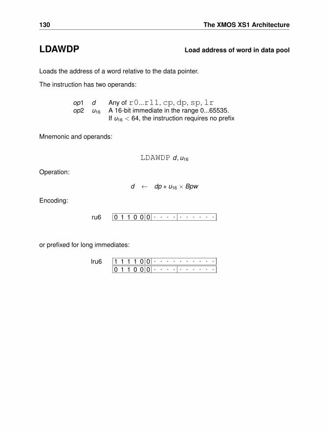
130 The XMOS XS1 Architecture
LDAWDP Load address of word in data pool
Loads the address of a word relative to the data pointer.
The instruction has two operands:
op1 d Any of r0...r11, cp, dp, sp, lrop2 u16 A 16-bit immediate in the range 0...65535.
If u16 < 64, the instruction requires no prefix
Mnemonic and operands:
LDAWDP d , u16
Operation:
d ← dp + u16 × Bpw
Encoding:
0 1 1 0 0 0 . . . . . . . . . .ru6
or prefixed for long immediates:
1 1 1 1 0 0 . . . . . . . . . .0 1 1 0 0 0 . . . . . . . . . .
lru6
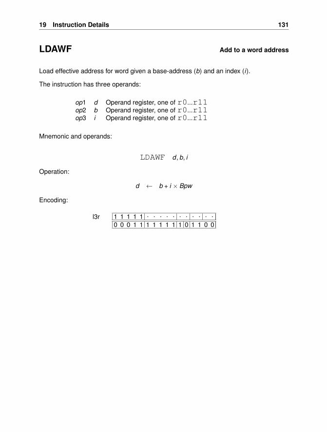
19 Instruction Details 131
LDAWF Add to a word address
Load effective address for word given a base-address (b) and an index (i).
The instruction has three operands:
op1 d Operand register, one of r0...r11op2 b Operand register, one of r0...r11op3 i Operand register, one of r0...r11
Mnemonic and operands:
LDAWF d , b, i
Operation:
d ← b + i × Bpw
Encoding:
1 1 1 1 1 . . . . . . . . . . .0 0 0 1 1 1 1 1 1 1 1 0 1 1 0 0
l3r
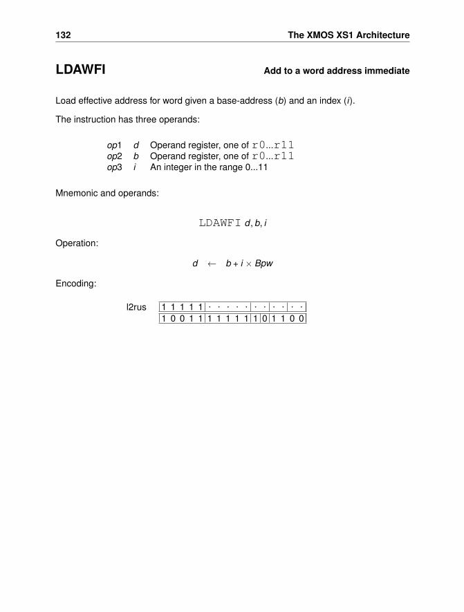
132 The XMOS XS1 Architecture
LDAWFI Add to a word address immediate
Load effective address for word given a base-address (b) and an index (i).
The instruction has three operands:
op1 d Operand register, one of r0...r11op2 b Operand register, one of r0...r11op3 i An integer in the range 0...11
Mnemonic and operands:
LDAWFI d , b, i
Operation:
d ← b + i × Bpw
Encoding:
1 1 1 1 1 . . . . . . . . . . .
1 0 0 1 1 1 1 1 1 1 1 0 1 1 0 0l2rus
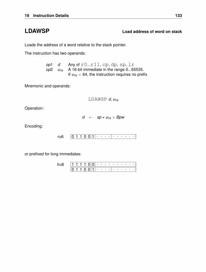
19 Instruction Details 133
LDAWSP Load address of word on stack
Loads the address of a word relative to the stack pointer.
The instruction has two operands:
op1 d Any of r0...r11, cp, dp, sp, lrop2 u16 A 16-bit immediate in the range 0...65535.
If u16 < 64, the instruction requires no prefix
Mnemonic and operands:
LDAWSP d , u16
Operation:
d ← sp + u16 × Bpw
Encoding:
0 1 1 0 0 1 . . . . . . . . . .ru6
or prefixed for long immediates:
1 1 1 1 0 0 . . . . . . . . . .0 1 1 0 0 1 . . . . . . . . . .
lru6
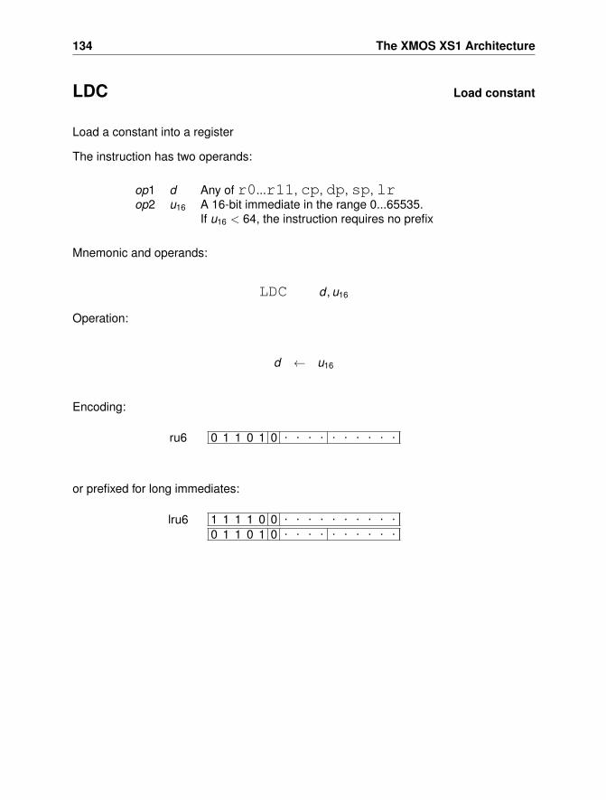
134 The XMOS XS1 Architecture
LDC Load constant
Load a constant into a register
The instruction has two operands:
op1 d Any of r0...r11, cp, dp, sp, lrop2 u16 A 16-bit immediate in the range 0...65535.
If u16 < 64, the instruction requires no prefix
Mnemonic and operands:
LDC d , u16
Operation:
d ← u16
Encoding:
0 1 1 0 1 0 . . . . . . . . . .ru6
or prefixed for long immediates:
1 1 1 1 0 0 . . . . . . . . . .0 1 1 0 1 0 . . . . . . . . . .
lru6
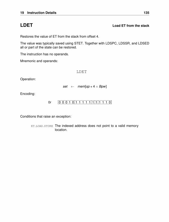
19 Instruction Details 135
LDET Load ET from the stack
Restores the value of ET from the stack from offset 4.
The value was typically saved using STET. Together with LDSPC, LDSSR, and LDSEDall or part of the state can be restored.
The instruction has no operands.
Mnemonic and operands:
LDET
Operation:
set ← mem[sp + 4× Bpw ]
Encoding:
0 0 0 1 0 1 1 1 1 1 1 1 1 1 1 00r
Conditions that raise an exception:
ET LOAD STORE The indexed address does not point to a valid memorylocation.
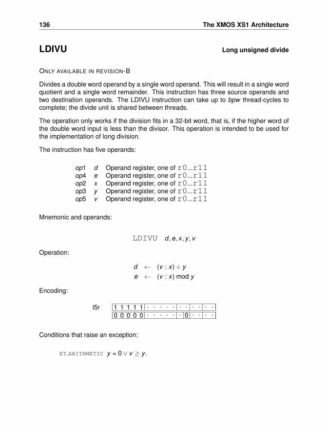
136 The XMOS XS1 Architecture
LDIVU Long unsigned divide
ONLY AVAILABLE IN REVISION-B
Divides a double word operand by a single word operand. This will result in a single wordquotient and a single word remainder. This instruction has three source operands andtwo destination operands. The LDIVU instruction can take up to bpw thread-cycles tocomplete; the divide unit is shared between threads.
The operation only works if the division fits in a 32-bit word, that is, if the higher word ofthe double word input is less than the divisor. This operation is intended to be used forthe implementation of long division.
The instruction has five operands:
op1 d Operand register, one of r0...r11op4 e Operand register, one of r0...r11op2 x Operand register, one of r0...r11op3 y Operand register, one of r0...r11op5 v Operand register, one of r0...r11
Mnemonic and operands:
LDIVU d , e, x , y , v
Operation:
d ← (v : x)÷ ye ← (v : x) mod y
Encoding:
1 1 1 1 1 . . . . . . . . . . .0 0 0 0 0 . . . . . . 0 . . . .
l5r
Conditions that raise an exception:
ET ARITHMETIC y = 0 ∨ v ≥ y .
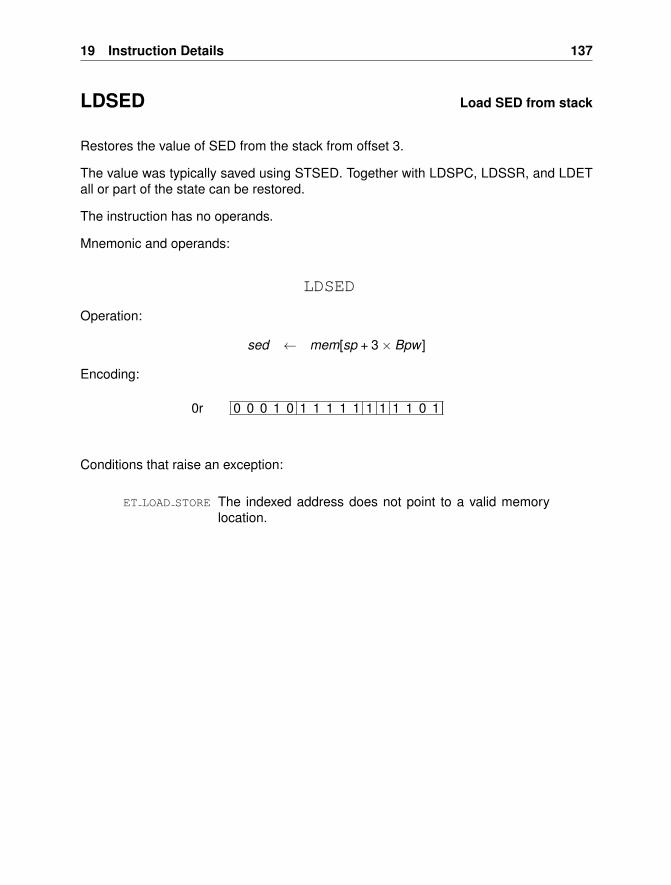
19 Instruction Details 137
LDSED Load SED from stack
Restores the value of SED from the stack from offset 3.
The value was typically saved using STSED. Together with LDSPC, LDSSR, and LDETall or part of the state can be restored.
The instruction has no operands.
Mnemonic and operands:
LDSED
Operation:
sed ← mem[sp + 3× Bpw ]
Encoding:
0 0 0 1 0 1 1 1 1 1 1 1 1 1 0 10r
Conditions that raise an exception:
ET LOAD STORE The indexed address does not point to a valid memorylocation.
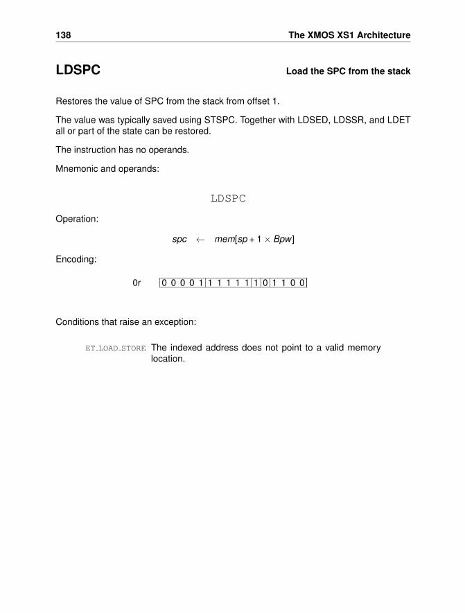
138 The XMOS XS1 Architecture
LDSPC Load the SPC from the stack
Restores the value of SPC from the stack from offset 1.
The value was typically saved using STSPC. Together with LDSED, LDSSR, and LDETall or part of the state can be restored.
The instruction has no operands.
Mnemonic and operands:
LDSPC
Operation:
spc ← mem[sp + 1× Bpw ]
Encoding:
0 0 0 0 1 1 1 1 1 1 1 0 1 1 0 00r
Conditions that raise an exception:
ET LOAD STORE The indexed address does not point to a valid memorylocation.
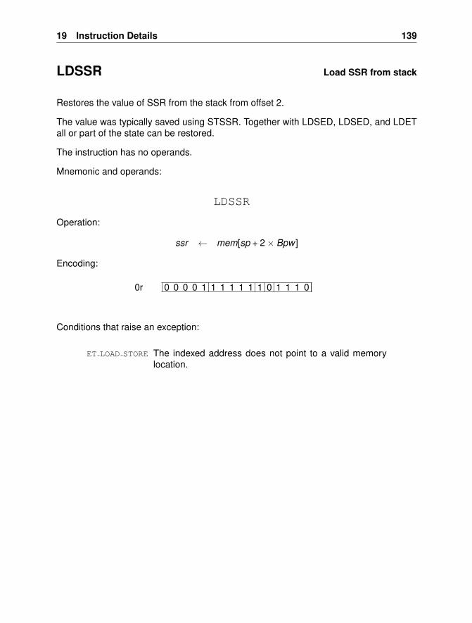
19 Instruction Details 139
LDSSR Load SSR from stack
Restores the value of SSR from the stack from offset 2.
The value was typically saved using STSSR. Together with LDSED, LDSED, and LDETall or part of the state can be restored.
The instruction has no operands.
Mnemonic and operands:
LDSSR
Operation:
ssr ← mem[sp + 2× Bpw ]
Encoding:
0 0 0 0 1 1 1 1 1 1 1 0 1 1 1 00r
Conditions that raise an exception:
ET LOAD STORE The indexed address does not point to a valid memorylocation.
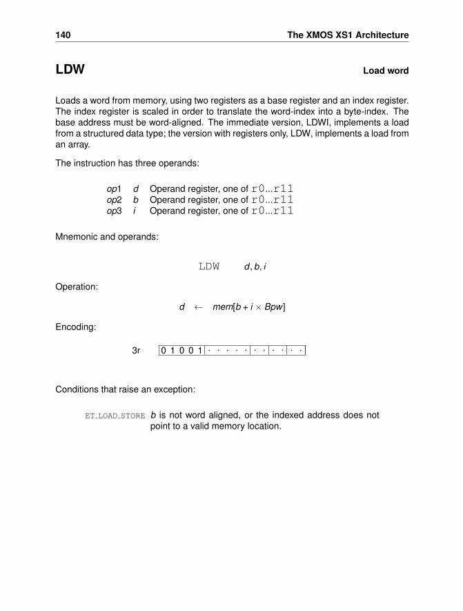
140 The XMOS XS1 Architecture
LDW Load word
Loads a word from memory, using two registers as a base register and an index register.The index register is scaled in order to translate the word-index into a byte-index. Thebase address must be word-aligned. The immediate version, LDWI, implements a loadfrom a structured data type; the version with registers only, LDW, implements a load froman array.
The instruction has three operands:
op1 d Operand register, one of r0...r11op2 b Operand register, one of r0...r11op3 i Operand register, one of r0...r11
Mnemonic and operands:
LDW d , b, i
Operation:
d ← mem[b + i × Bpw ]
Encoding:
0 1 0 0 1 . . . . . . . . . . .3r
Conditions that raise an exception:
ET LOAD STORE b is not word aligned, or the indexed address does notpoint to a valid memory location.
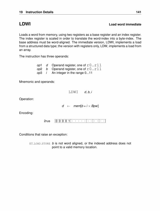
19 Instruction Details 141
LDWI Load word immediate
Loads a word from memory, using two registers as a base register and an index register.The index register is scaled in order to translate the word-index into a byte-index. Thebase address must be word-aligned. The immediate version, LDWI, implements a loadfrom a structured data type; the version with registers only, LDW, implements a load froman array.
The instruction has three operands:
op1 d Operand register, one of r0...r11op2 b Operand register, one of r0...r11op3 i An integer in the range 0...11
Mnemonic and operands:
LDWI d , b, i
Operation:
d ← mem[b + i × Bpw ]
Encoding:
0 0 0 0 1 . . . . . . . . . . .2rus
Conditions that raise an exception:
ET LOAD STORE b is not word aligned, or the indexed address does notpoint to a valid memory location.
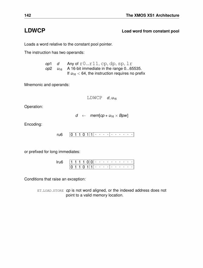
142 The XMOS XS1 Architecture
LDWCP Load word from constant pool
Loads a word relative to the constant pool pointer.
The instruction has two operands:
op1 d Any of r0...r11, cp, dp, sp, lrop2 u16 A 16-bit immediate in the range 0...65535.
If u16 < 64, the instruction requires no prefix
Mnemonic and operands:
LDWCP d , u16
Operation:
d ← mem[cp + u16 × Bpw ]
Encoding:
0 1 1 0 1 1 . . . . . . . . . .ru6
or prefixed for long immediates:
1 1 1 1 0 0 . . . . . . . . . .0 1 1 0 1 1 . . . . . . . . . .
lru6
Conditions that raise an exception:
ET LOAD STORE cp is not word aligned, or the indexed address does notpoint to a valid memory location.
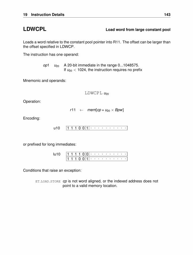
19 Instruction Details 143
LDWCPL Load word from large constant pool
Loads a word relative to the constant pool pointer into R11. The offset can be larger thanthe offset specified in LDWCP.
The instruction has one operand:
op1 u20 A 20-bit immediate in the range 0...1048575.If u20 < 1024, the instruction requires no prefix
Mnemonic and operands:
LDWCPL u20
Operation:
r11 ← mem[cp + u20 × Bpw ]
Encoding:
1 1 1 0 0 1 . . . . . . . . . .u10
or prefixed for long immediates:
1 1 1 1 0 0 . . . . . . . . . .
1 1 1 0 0 1 . . . . . . . . . .lu10
Conditions that raise an exception:
ET LOAD STORE cp is not word aligned, or the indexed address does notpoint to a valid memory location.
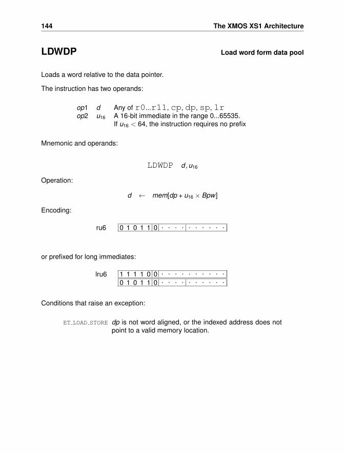
144 The XMOS XS1 Architecture
LDWDP Load word form data pool
Loads a word relative to the data pointer.
The instruction has two operands:
op1 d Any of r0...r11, cp, dp, sp, lrop2 u16 A 16-bit immediate in the range 0...65535.
If u16 < 64, the instruction requires no prefix
Mnemonic and operands:
LDWDP d , u16
Operation:
d ← mem[dp + u16 × Bpw ]
Encoding:
0 1 0 1 1 0 . . . . . . . . . .ru6
or prefixed for long immediates:
1 1 1 1 0 0 . . . . . . . . . .0 1 0 1 1 0 . . . . . . . . . .
lru6
Conditions that raise an exception:
ET LOAD STORE dp is not word aligned, or the indexed address does notpoint to a valid memory location.
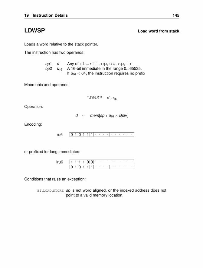
19 Instruction Details 145
LDWSP Load word from stack
Loads a word relative to the stack pointer.
The instruction has two operands:
op1 d Any of r0...r11, cp, dp, sp, lrop2 u16 A 16-bit immediate in the range 0...65535.
If u16 < 64, the instruction requires no prefix
Mnemonic and operands:
LDWSP d , u16
Operation:
d ← mem[sp + u16 × Bpw ]
Encoding:
0 1 0 1 1 1 . . . . . . . . . .ru6
or prefixed for long immediates:
1 1 1 1 0 0 . . . . . . . . . .0 1 0 1 1 1 . . . . . . . . . .
lru6
Conditions that raise an exception:
ET LOAD STORE sp is not word aligned, or the indexed address does notpoint to a valid memory location.
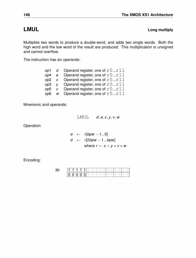
146 The XMOS XS1 Architecture
LMUL Long multiply
Multiplies two words to produce a double-word, and adds two single words. Both thehigh word and the low word of the result are produced. This multiplication is unsignedand cannot overflow.
The instruction has six operands:
op1 d Operand register, one of r0...r11op4 e Operand register, one of r0...r11op2 x Operand register, one of r0...r11op3 y Operand register, one of r0...r11op5 v Operand register, one of r0...r11op6 w Operand register, one of r0...r11
Mnemonic and operands:
LMUL d , e, x , y , v , w
Operation:
e ← r [bpw − 1...0]d ← r [2bpw − 1...bpw ]
where r ← x × y + v + w
Encoding:
1 1 1 1 1 . . . . . . . . . . .0 0 0 0 0 . . . . . . . . . . .
l6r
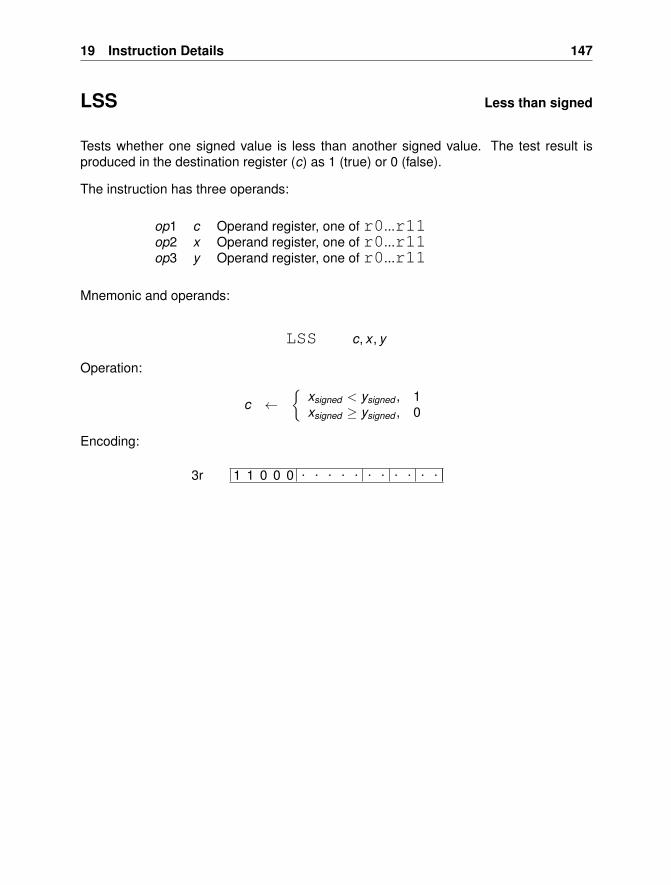
19 Instruction Details 147
LSS Less than signed
Tests whether one signed value is less than another signed value. The test result isproduced in the destination register (c) as 1 (true) or 0 (false).
The instruction has three operands:
op1 c Operand register, one of r0...r11op2 x Operand register, one of r0...r11op3 y Operand register, one of r0...r11
Mnemonic and operands:
LSS c, x , y
Operation:
c ←{
xsigned < ysigned , 1xsigned ≥ ysigned , 0
Encoding:
1 1 0 0 0 . . . . . . . . . . .3r
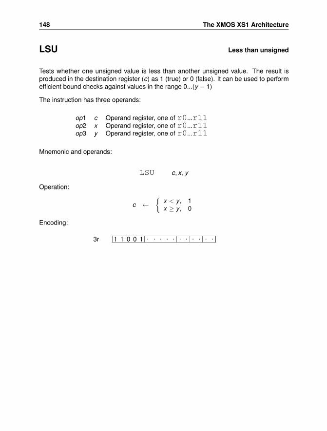
148 The XMOS XS1 Architecture
LSU Less than unsigned
Tests whether one unsigned value is less than another unsigned value. The result isproduced in the destination register (c) as 1 (true) or 0 (false). It can be used to performefficient bound checks against values in the range 0...(y − 1)
The instruction has three operands:
op1 c Operand register, one of r0...r11op2 x Operand register, one of r0...r11op3 y Operand register, one of r0...r11
Mnemonic and operands:
LSU c, x , y
Operation:
c ←{
x < y , 1x ≥ y , 0
Encoding:
1 1 0 0 1 . . . . . . . . . . .3r
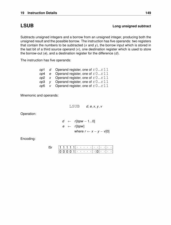
19 Instruction Details 149
LSUB Long unsigned subtract
Subtracts unsigned integers and a borrow from an unsigned integer, producing both theunsigned result and the possible borrow. The instruction has five operands: two registersthat contain the numbers to be subtracted (x and y ), the borrow input which is stored inthe last bit of a third source operand (v ), one destination register which is used to storethe borrow-out (e), and a destination register for the difference (d).
The instruction has five operands:
op1 d Operand register, one of r0...r11op4 e Operand register, one of r0...r11op2 x Operand register, one of r0...r11op3 y Operand register, one of r0...r11op5 v Operand register, one of r0...r11
Mnemonic and operands:
LSUB d , e, x , y , v
Operation:
d ← r [bpw − 1...0]e ← r [bpw ]
where r ← x − y − v [0]
Encoding:
1 1 1 1 1 . . . . . . . . . . .0 0 0 0 1 . . . . . . 0 . . . .
l5r
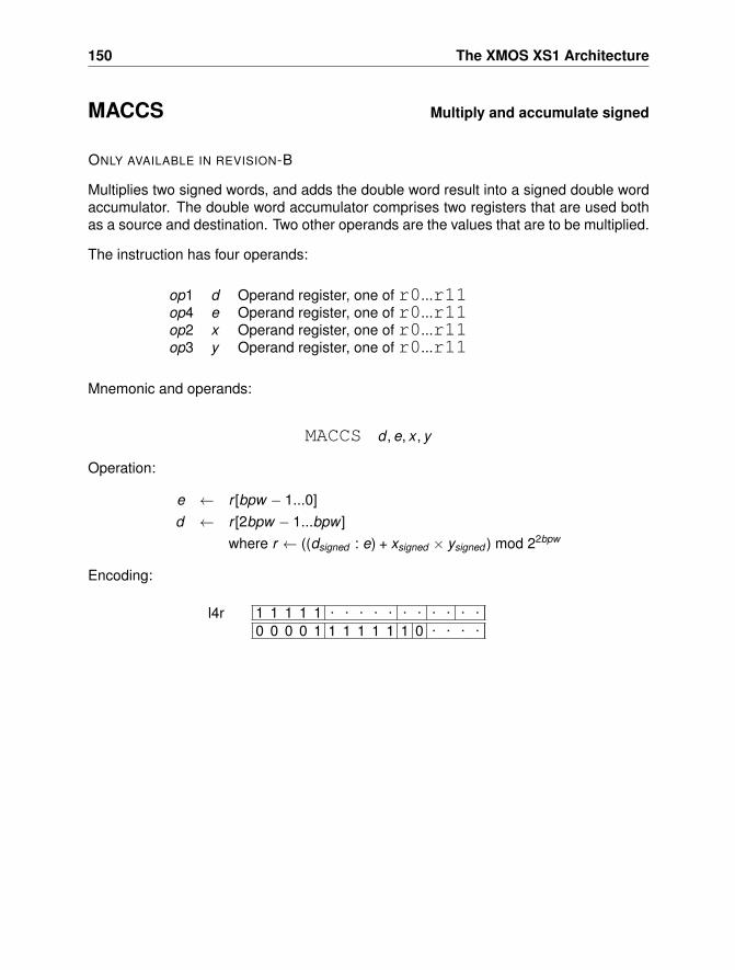
150 The XMOS XS1 Architecture
MACCS Multiply and accumulate signed
ONLY AVAILABLE IN REVISION-B
Multiplies two signed words, and adds the double word result into a signed double wordaccumulator. The double word accumulator comprises two registers that are used bothas a source and destination. Two other operands are the values that are to be multiplied.
The instruction has four operands:
op1 d Operand register, one of r0...r11op4 e Operand register, one of r0...r11op2 x Operand register, one of r0...r11op3 y Operand register, one of r0...r11
Mnemonic and operands:
MACCS d , e, x , y
Operation:
e ← r [bpw − 1...0]d ← r [2bpw − 1...bpw ]
where r ← ((dsigned : e) + xsigned × ysigned ) mod 22bpw
Encoding:
1 1 1 1 1 . . . . . . . . . . .0 0 0 0 1 1 1 1 1 1 1 0 . . . .
l4r
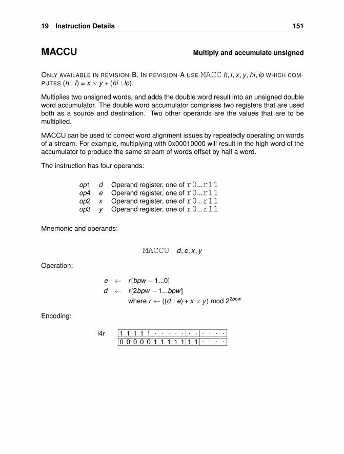
19 Instruction Details 151
MACCU Multiply and accumulate unsigned
ONLY AVAILABLE IN REVISION-B. IN REVISION-A USE MACC h, l , x , y , hi , lo WHICH COM-PUTES (h : l) = x × y + (hi : lo).
Multiplies two unsigned words, and adds the double word result into an unsigned doubleword accumulator. The double word accumulator comprises two registers that are usedboth as a source and destination. Two other operands are the values that are to bemultiplied.
MACCU can be used to correct word alignment issues by repeatedly operating on wordsof a stream. For example, multiplying with 0x00010000 will result in the high word of theaccumulator to produce the same stream of words offset by half a word.
The instruction has four operands:
op1 d Operand register, one of r0...r11op4 e Operand register, one of r0...r11op2 x Operand register, one of r0...r11op3 y Operand register, one of r0...r11
Mnemonic and operands:
MACCU d , e, x , y
Operation:
e ← r [bpw − 1...0]d ← r [2bpw − 1...bpw ]
where r ← ((d : e) + x × y ) mod 22bpw
Encoding:
1 1 1 1 1 . . . . . . . . . . .0 0 0 0 0 1 1 1 1 1 1 1 . . . .
l4r
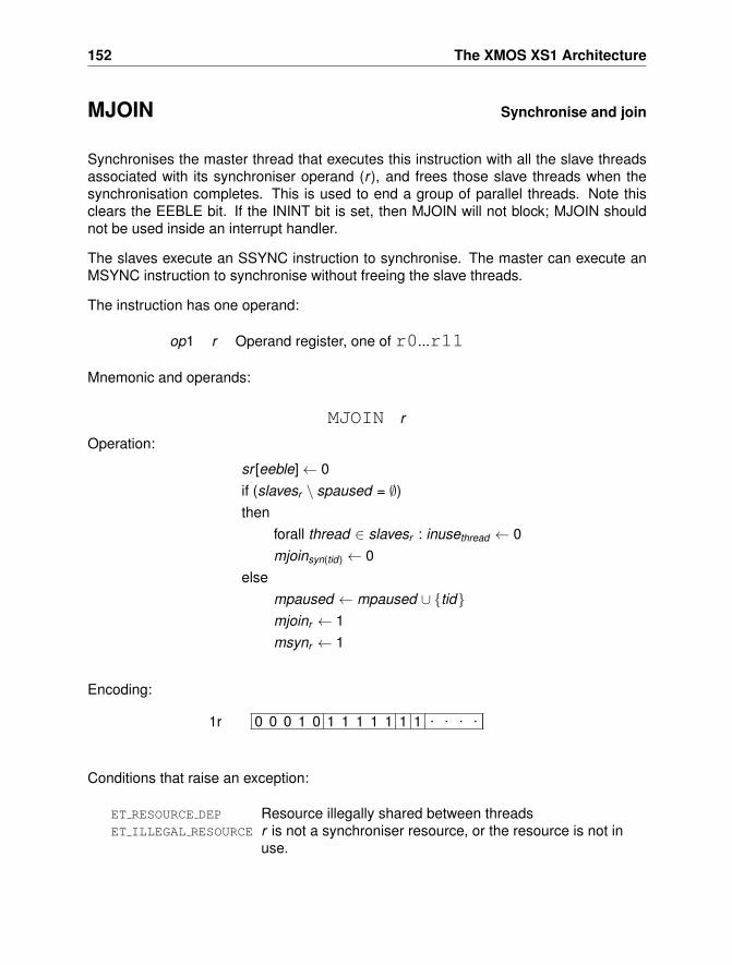
152 The XMOS XS1 Architecture
MJOIN Synchronise and join
Synchronises the master thread that executes this instruction with all the slave threadsassociated with its synchroniser operand (r ), and frees those slave threads when thesynchronisation completes. This is used to end a group of parallel threads. Note thisclears the EEBLE bit. If the ININT bit is set, then MJOIN will not block; MJOIN shouldnot be used inside an interrupt handler.
The slaves execute an SSYNC instruction to synchronise. The master can execute anMSYNC instruction to synchronise without freeing the slave threads.
The instruction has one operand:
op1 r Operand register, one of r0...r11
Mnemonic and operands:
MJOIN r
Operation:
sr [eeble]← 0if (slavesr \ spaused = ∅)then
forall thread ∈ slavesr : inusethread ← 0mjoinsyn(tid) ← 0
elsempaused ← mpaused ∪ {tid}mjoinr ← 1msynr ← 1
Encoding:
0 0 0 1 0 1 1 1 1 1 1 1 . . . .1r
Conditions that raise an exception:
ET RESOURCE DEP Resource illegally shared between threadsET ILLEGAL RESOURCE r is not a synchroniser resource, or the resource is not in
use.
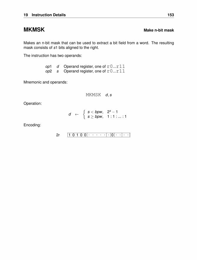
19 Instruction Details 153
MKMSK Make n-bit mask
Makes an n-bit mask that can be used to extract a bit field from a word. The resultingmask consists of s1 bits aligned to the right.
The instruction has two operands:
op1 d Operand register, one of r0...r11op2 s Operand register, one of r0...r11
Mnemonic and operands:
MKMSK d , s
Operation:
d ←{
s < bpw , 2s − 1s ≥ bpw , 1 : 1 : ... : 1
Encoding:
1 0 1 0 0 . . . . . . 0 . . . .2r
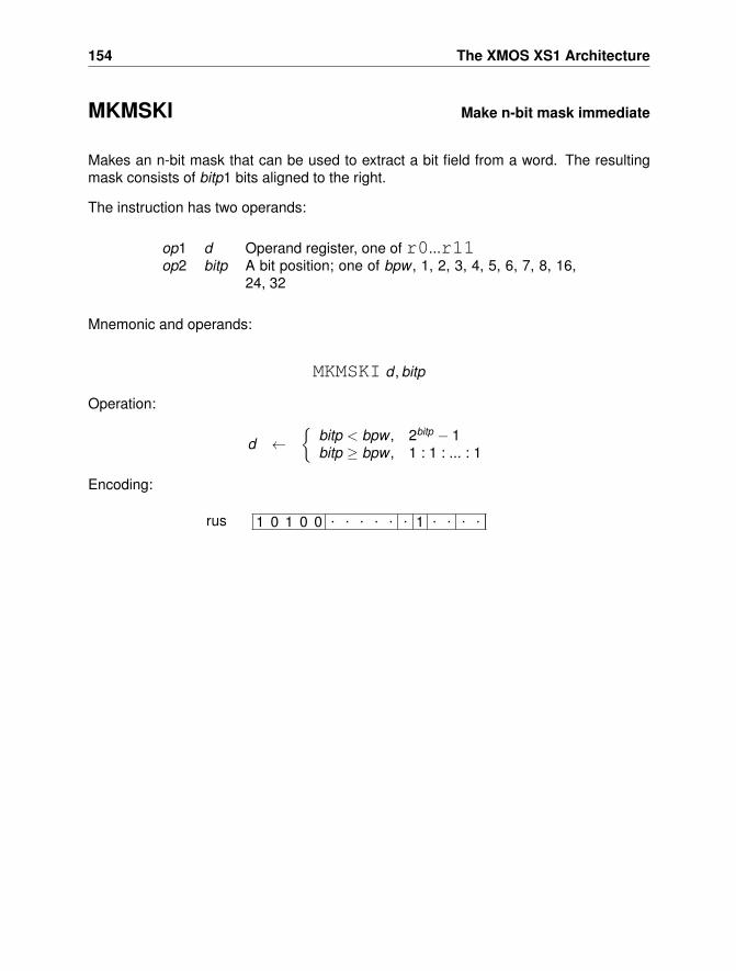
154 The XMOS XS1 Architecture
MKMSKI Make n-bit mask immediate
Makes an n-bit mask that can be used to extract a bit field from a word. The resultingmask consists of bitp1 bits aligned to the right.
The instruction has two operands:
op1 d Operand register, one of r0...r11op2 bitp A bit position; one of bpw , 1, 2, 3, 4, 5, 6, 7, 8, 16,
24, 32
Mnemonic and operands:
MKMSKI d , bitp
Operation:
d ←{
bitp < bpw , 2bitp − 1bitp ≥ bpw , 1 : 1 : ... : 1
Encoding:
1 0 1 0 0 . . . . . . 1 . . . .rus
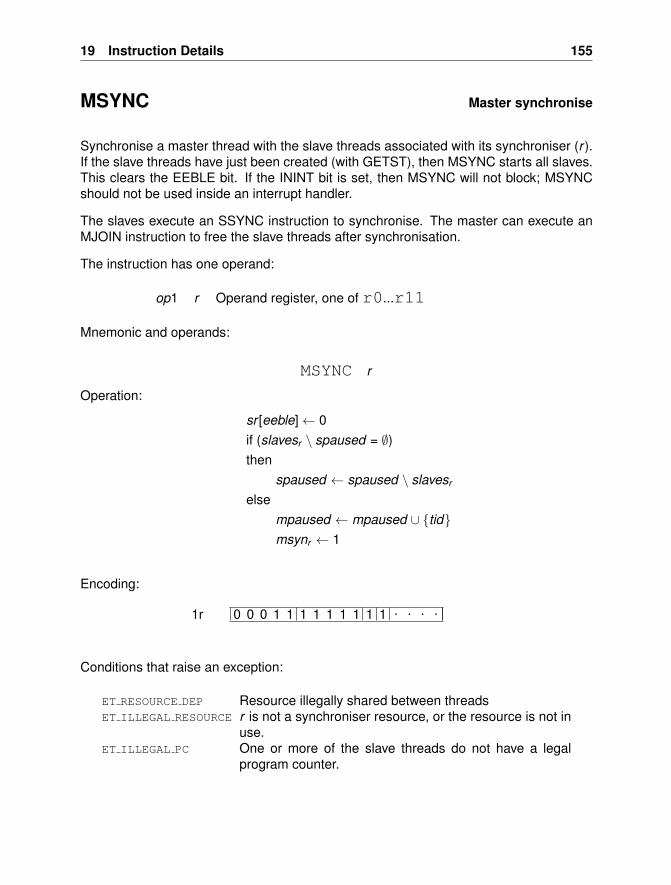
19 Instruction Details 155
MSYNC Master synchronise
Synchronise a master thread with the slave threads associated with its synchroniser (r ).If the slave threads have just been created (with GETST), then MSYNC starts all slaves.This clears the EEBLE bit. If the ININT bit is set, then MSYNC will not block; MSYNCshould not be used inside an interrupt handler.
The slaves execute an SSYNC instruction to synchronise. The master can execute anMJOIN instruction to free the slave threads after synchronisation.
The instruction has one operand:
op1 r Operand register, one of r0...r11
Mnemonic and operands:
MSYNC r
Operation:
sr [eeble]← 0if (slavesr \ spaused = ∅)then
spaused ← spaused \ slavesr
elsempaused ← mpaused ∪ {tid}msynr ← 1
Encoding:
0 0 0 1 1 1 1 1 1 1 1 1 . . . .1r
Conditions that raise an exception:
ET RESOURCE DEP Resource illegally shared between threadsET ILLEGAL RESOURCE r is not a synchroniser resource, or the resource is not in
use.ET ILLEGAL PC One or more of the slave threads do not have a legal
program counter.
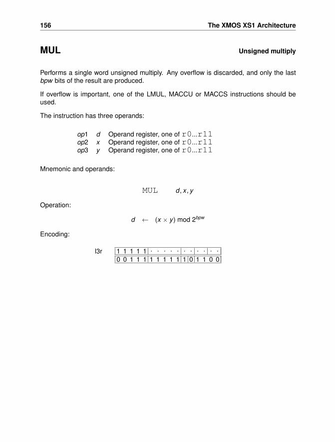
156 The XMOS XS1 Architecture
MUL Unsigned multiply
Performs a single word unsigned multiply. Any overflow is discarded, and only the lastbpw bits of the result are produced.
If overflow is important, one of the LMUL, MACCU or MACCS instructions should beused.
The instruction has three operands:
op1 d Operand register, one of r0...r11op2 x Operand register, one of r0...r11op3 y Operand register, one of r0...r11
Mnemonic and operands:
MUL d , x , y
Operation:
d ← (x × y ) mod 2bpw
Encoding:
1 1 1 1 1 . . . . . . . . . . .0 0 1 1 1 1 1 1 1 1 1 0 1 1 0 0
l3r
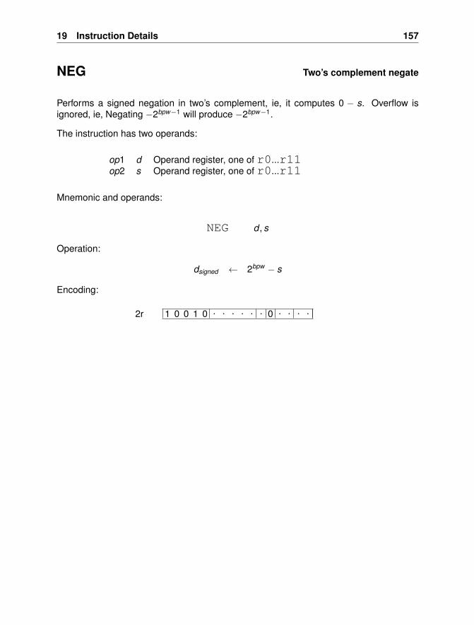
19 Instruction Details 157
NEG Two’s complement negate
Performs a signed negation in two’s complement, ie, it computes 0 − s. Overflow isignored, ie, Negating −2bpw−1 will produce −2bpw−1.
The instruction has two operands:
op1 d Operand register, one of r0...r11op2 s Operand register, one of r0...r11
Mnemonic and operands:
NEG d , s
Operation:
dsigned ← 2bpw − s
Encoding:
1 0 0 1 0 . . . . . . 0 . . . .2r
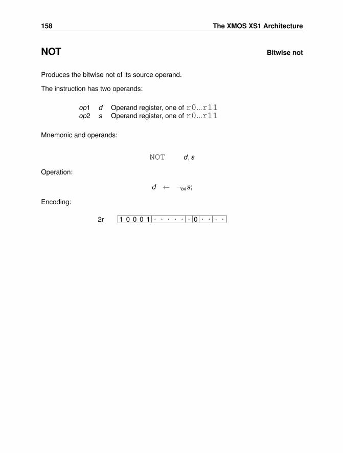
158 The XMOS XS1 Architecture
NOT Bitwise not
Produces the bitwise not of its source operand.
The instruction has two operands:
op1 d Operand register, one of r0...r11op2 s Operand register, one of r0...r11
Mnemonic and operands:
NOT d , s
Operation:
d ← ¬bits;
Encoding:
1 0 0 0 1 . . . . . . 0 . . . .2r
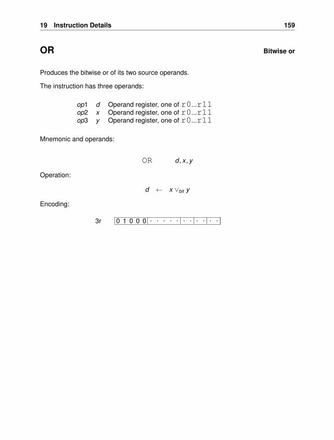
19 Instruction Details 159
OR Bitwise or
Produces the bitwise or of its two source operands.
The instruction has three operands:
op1 d Operand register, one of r0...r11op2 x Operand register, one of r0...r11op3 y Operand register, one of r0...r11
Mnemonic and operands:
OR d , x , y
Operation:
d ← x ∨bit y
Encoding:
0 1 0 0 0 . . . . . . . . . . .3r
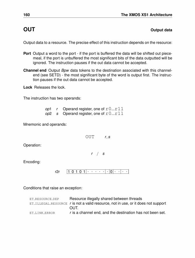
160 The XMOS XS1 Architecture
OUT Output data
Output data to a resource. The precise effect of this instruction depends on the resource:
Port Output a word to the port - if the port is buffered the data will be shifted out piece-meal, if the port is unbuffered the most significant bits of the data outputted will beignored. The instruction pauses if the out data cannot be accepted.
Channel end Output Bpw data tokens to the destination associated with this channel-end (see SETD) - the most significant byte of the word is output first. The instruc-tion pauses if the out data cannot be accepted.
Lock Releases the lock.
The instruction has two operands:
op1 r Operand register, one of r0...r11op2 s Operand register, one of r0...r11
Mnemonic and operands:
OUT r , s
Operation:
r / s
Encoding:
1 0 1 0 1 . . . . . . 0 . . . .r2r
Conditions that raise an exception:
ET RESOURCE DEP Resource illegally shared between threadsET ILLEGAL RESOURCE r is not a valid resource, not in use, or it does not support
OUT.ET LINK ERROR r is a channel end, and the destination has not been set.
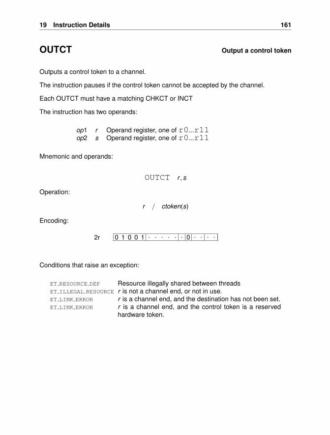
19 Instruction Details 161
OUTCT Output a control token
Outputs a control token to a channel.
The instruction pauses if the control token cannot be accepted by the channel.
Each OUTCT must have a matching CHKCT or INCT
The instruction has two operands:
op1 r Operand register, one of r0...r11op2 s Operand register, one of r0...r11
Mnemonic and operands:
OUTCT r , s
Operation:
r / ctoken(s)
Encoding:
0 1 0 0 1 . . . . . . 0 . . . .2r
Conditions that raise an exception:
ET RESOURCE DEP Resource illegally shared between threadsET ILLEGAL RESOURCE r is not a channel end, or not in use.ET LINK ERROR r is a channel end, and the destination has not been set.ET LINK ERROR r is a channel end, and the control token is a reserved
hardware token.
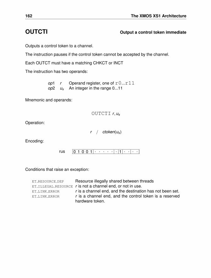
162 The XMOS XS1 Architecture
OUTCTI Output a control token immediate
Outputs a control token to a channel.
The instruction pauses if the control token cannot be accepted by the channel.
Each OUTCT must have a matching CHKCT or INCT
The instruction has two operands:
op1 r Operand register, one of r0...r11op2 us An integer in the range 0...11
Mnemonic and operands:
OUTCTI r , us
Operation:
r / ctoken(us)
Encoding:
0 1 0 0 1 . . . . . . 1 . . . .rus
Conditions that raise an exception:
ET RESOURCE DEP Resource illegally shared between threadsET ILLEGAL RESOURCE r is not a channel end, or not in use.ET LINK ERROR r is a channel end, and the destination has not been set.ET LINK ERROR r is a channel end, and the control token is a reserved
hardware token.
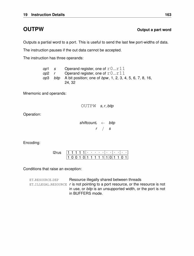
19 Instruction Details 163
OUTPW Output a part word
Outputs a partial word to a port. This is useful to send the last few port-widths of data.
The instruction pauses if the out data cannot be accepted.
The instruction has three operands:
op1 s Operand register, one of r0...r11op2 r Operand register, one of r0...r11op3 bitp A bit position; one of bpw , 1, 2, 3, 4, 5, 6, 7, 8, 16,
24, 32
Mnemonic and operands:
OUTPW s, r , bitp
Operation:
shiftcountr ← bitpr / s
Encoding:
1 1 1 1 1 . . . . . . . . . . .
1 0 0 1 0 1 1 1 1 1 1 0 1 1 0 1l2rus
Conditions that raise an exception:
ET RESOURCE DEP Resource illegally shared between threadsET ILLEGAL RESOURCE r is not pointing to a port resource, or the resource is not
in use, or bitp is an unsupported width, or the port is notin BUFFERS mode.
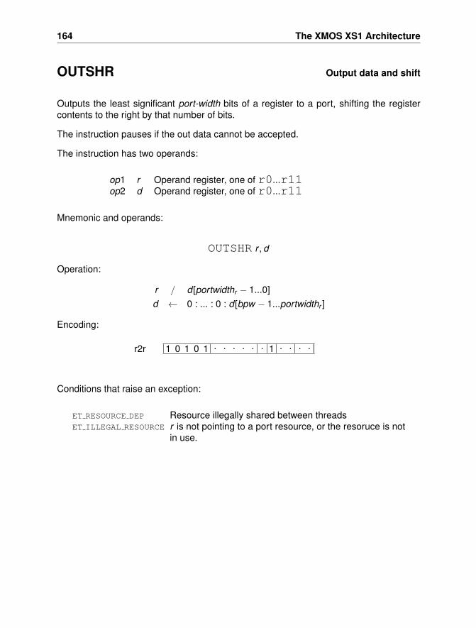
164 The XMOS XS1 Architecture
OUTSHR Output data and shift
Outputs the least significant port-width bits of a register to a port, shifting the registercontents to the right by that number of bits.
The instruction pauses if the out data cannot be accepted.
The instruction has two operands:
op1 r Operand register, one of r0...r11op2 d Operand register, one of r0...r11
Mnemonic and operands:
OUTSHR r , d
Operation:
r / d [portwidthr − 1...0]d ← 0 : ... : 0 : d [bpw − 1...portwidthr ]
Encoding:
1 0 1 0 1 . . . . . . 1 . . . .r2r
Conditions that raise an exception:
ET RESOURCE DEP Resource illegally shared between threadsET ILLEGAL RESOURCE r is not pointing to a port resource, or the resoruce is not
in use.
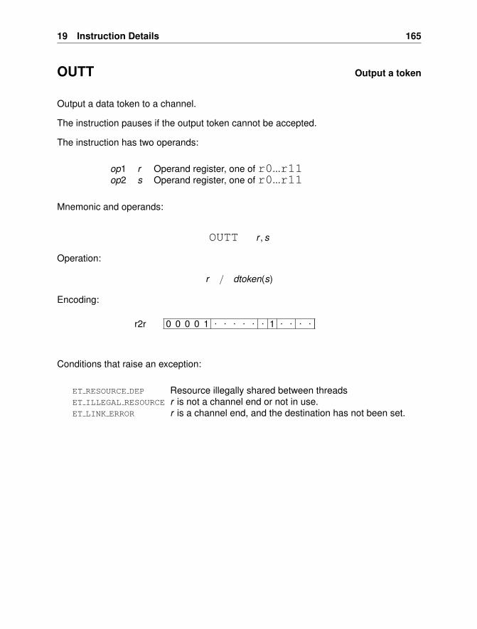
19 Instruction Details 165
OUTT Output a token
Output a data token to a channel.
The instruction pauses if the output token cannot be accepted.
The instruction has two operands:
op1 r Operand register, one of r0...r11op2 s Operand register, one of r0...r11
Mnemonic and operands:
OUTT r , s
Operation:
r / dtoken(s)
Encoding:
0 0 0 0 1 . . . . . . 1 . . . .r2r
Conditions that raise an exception:
ET RESOURCE DEP Resource illegally shared between threadsET ILLEGAL RESOURCE r is not a channel end or not in use.ET LINK ERROR r is a channel end, and the destination has not been set.
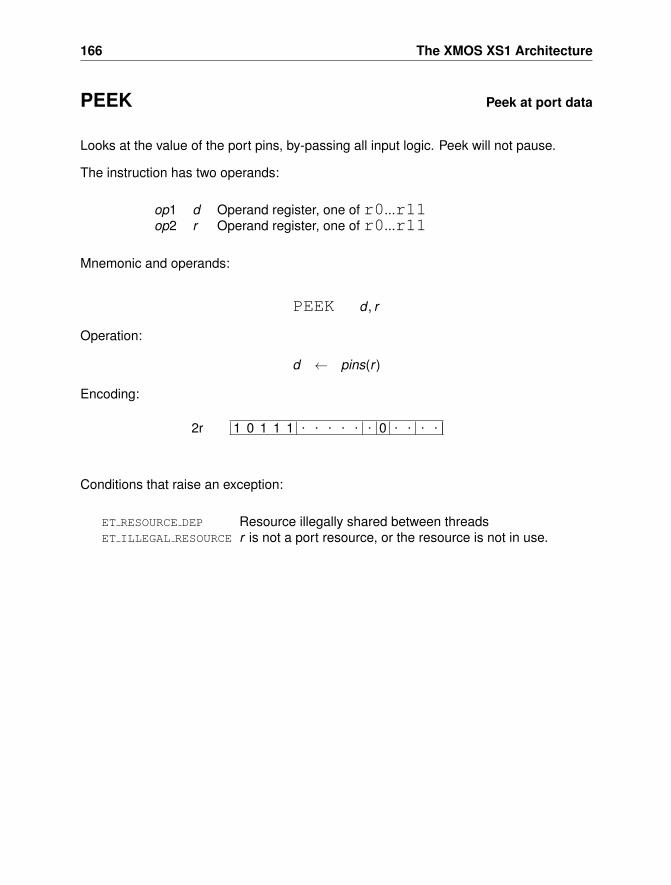
166 The XMOS XS1 Architecture
PEEK Peek at port data
Looks at the value of the port pins, by-passing all input logic. Peek will not pause.
The instruction has two operands:
op1 d Operand register, one of r0...r11op2 r Operand register, one of r0...r11
Mnemonic and operands:
PEEK d , r
Operation:
d ← pins(r )
Encoding:
1 0 1 1 1 . . . . . . 0 . . . .2r
Conditions that raise an exception:
ET RESOURCE DEP Resource illegally shared between threadsET ILLEGAL RESOURCE r is not a port resource, or the resource is not in use.
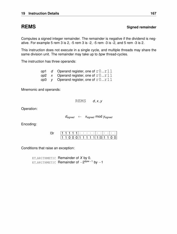
19 Instruction Details 167
REMS Signed remainder
Computes a signed integer remainder. The remainder is negative if the dividend is neg-ative. For example 5 rem 3 is 2, -5 rem 3 is -2, -5 rem -3 is -2, and 5 rem -3 is 2.
This instruction does not execute in a single cycle, and multiple threads may share thesame division unit. The remainder may take up to bpw thread-cycles.
The instruction has three operands:
op1 d Operand register, one of r0...r11op2 x Operand register, one of r0...r11op3 y Operand register, one of r0...r11
Mnemonic and operands:
REMS d , x , y
Operation:
dsigned ← xsigned mod ysigned
Encoding:
1 1 1 1 1 . . . . . . . . . . .
1 1 0 0 0 1 1 1 1 1 1 0 1 1 0 0l3r
Conditions that raise an exception:
ET ARITHMETIC Remainder of X by 0.ET ARITHMETIC Remainder of −2bpw−1 by −1
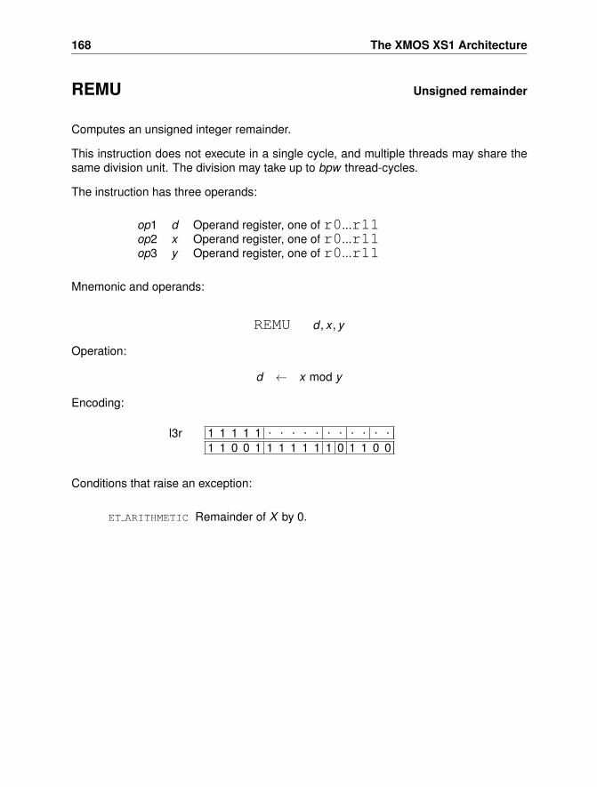
168 The XMOS XS1 Architecture
REMU Unsigned remainder
Computes an unsigned integer remainder.
This instruction does not execute in a single cycle, and multiple threads may share thesame division unit. The division may take up to bpw thread-cycles.
The instruction has three operands:
op1 d Operand register, one of r0...r11op2 x Operand register, one of r0...r11op3 y Operand register, one of r0...r11
Mnemonic and operands:
REMU d , x , y
Operation:
d ← x mod y
Encoding:
1 1 1 1 1 . . . . . . . . . . .
1 1 0 0 1 1 1 1 1 1 1 0 1 1 0 0l3r
Conditions that raise an exception:
ET ARITHMETIC Remainder of X by 0.
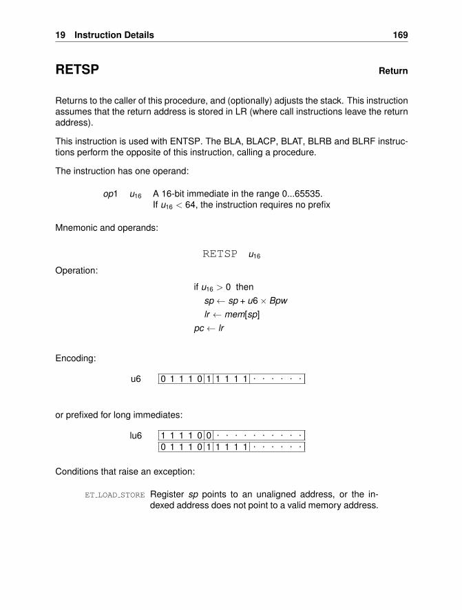
19 Instruction Details 169
RETSP Return
Returns to the caller of this procedure, and (optionally) adjusts the stack. This instructionassumes that the return address is stored in LR (where call instructions leave the returnaddress).
This instruction is used with ENTSP. The BLA, BLACP, BLAT, BLRB and BLRF instruc-tions perform the opposite of this instruction, calling a procedure.
The instruction has one operand:
op1 u16 A 16-bit immediate in the range 0...65535.If u16 < 64, the instruction requires no prefix
Mnemonic and operands:
RETSP u16
Operation:
if u16 > 0 thensp ← sp + u6× Bpwlr ← mem[sp]
pc ← lr
Encoding:
0 1 1 1 0 1 1 1 1 1 . . . . . .u6
or prefixed for long immediates:
1 1 1 1 0 0 . . . . . . . . . .0 1 1 1 0 1 1 1 1 1 . . . . . .
lu6
Conditions that raise an exception:
ET LOAD STORE Register sp points to an unaligned address, or the in-dexed address does not point to a valid memory address.
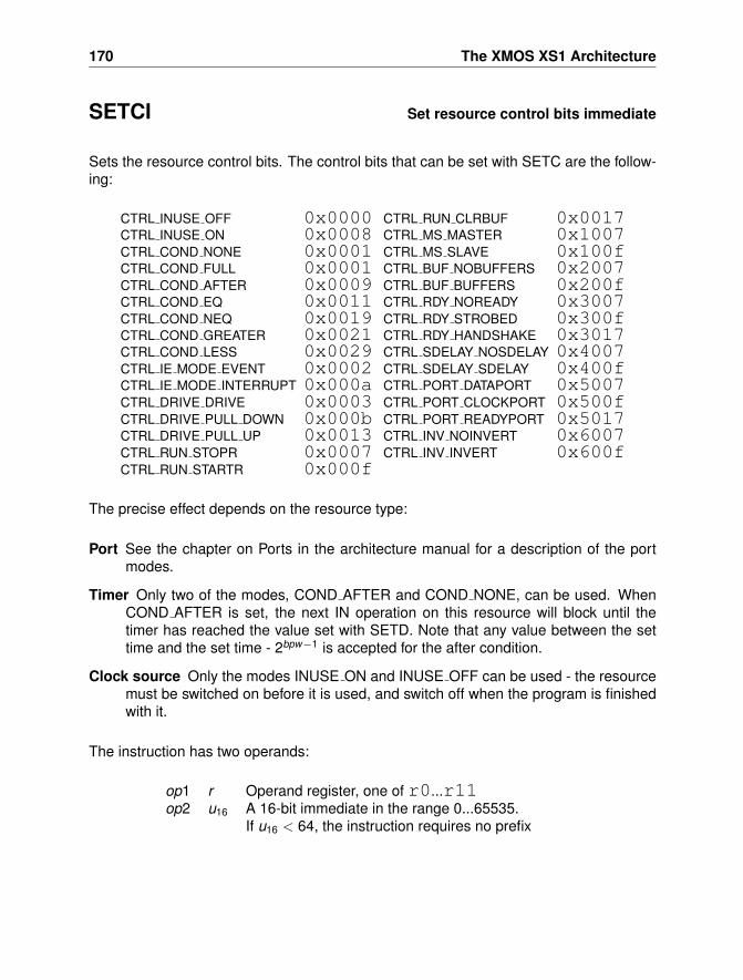
170 The XMOS XS1 Architecture
SETCI Set resource control bits immediate
Sets the resource control bits. The control bits that can be set with SETC are the follow-ing:
CTRL INUSE OFF 0x0000 CTRL RUN CLRBUF 0x0017CTRL INUSE ON 0x0008 CTRL MS MASTER 0x1007CTRL COND NONE 0x0001 CTRL MS SLAVE 0x100fCTRL COND FULL 0x0001 CTRL BUF NOBUFFERS 0x2007CTRL COND AFTER 0x0009 CTRL BUF BUFFERS 0x200fCTRL COND EQ 0x0011 CTRL RDY NOREADY 0x3007CTRL COND NEQ 0x0019 CTRL RDY STROBED 0x300fCTRL COND GREATER 0x0021 CTRL RDY HANDSHAKE 0x3017CTRL COND LESS 0x0029 CTRL SDELAY NOSDELAY 0x4007CTRL IE MODE EVENT 0x0002 CTRL SDELAY SDELAY 0x400fCTRL IE MODE INTERRUPT 0x000a CTRL PORT DATAPORT 0x5007CTRL DRIVE DRIVE 0x0003 CTRL PORT CLOCKPORT 0x500fCTRL DRIVE PULL DOWN 0x000b CTRL PORT READYPORT 0x5017CTRL DRIVE PULL UP 0x0013 CTRL INV NOINVERT 0x6007CTRL RUN STOPR 0x0007 CTRL INV INVERT 0x600fCTRL RUN STARTR 0x000f
The precise effect depends on the resource type:
Port See the chapter on Ports in the architecture manual for a description of the portmodes.
Timer Only two of the modes, COND AFTER and COND NONE, can be used. WhenCOND AFTER is set, the next IN operation on this resource will block until thetimer has reached the value set with SETD. Note that any value between the settime and the set time - 2bpw−1 is accepted for the after condition.
Clock source Only the modes INUSE ON and INUSE OFF can be used - the resourcemust be switched on before it is used, and switch off when the program is finishedwith it.
The instruction has two operands:
op1 r Operand register, one of r0...r11op2 u16 A 16-bit immediate in the range 0...65535.
If u16 < 64, the instruction requires no prefix
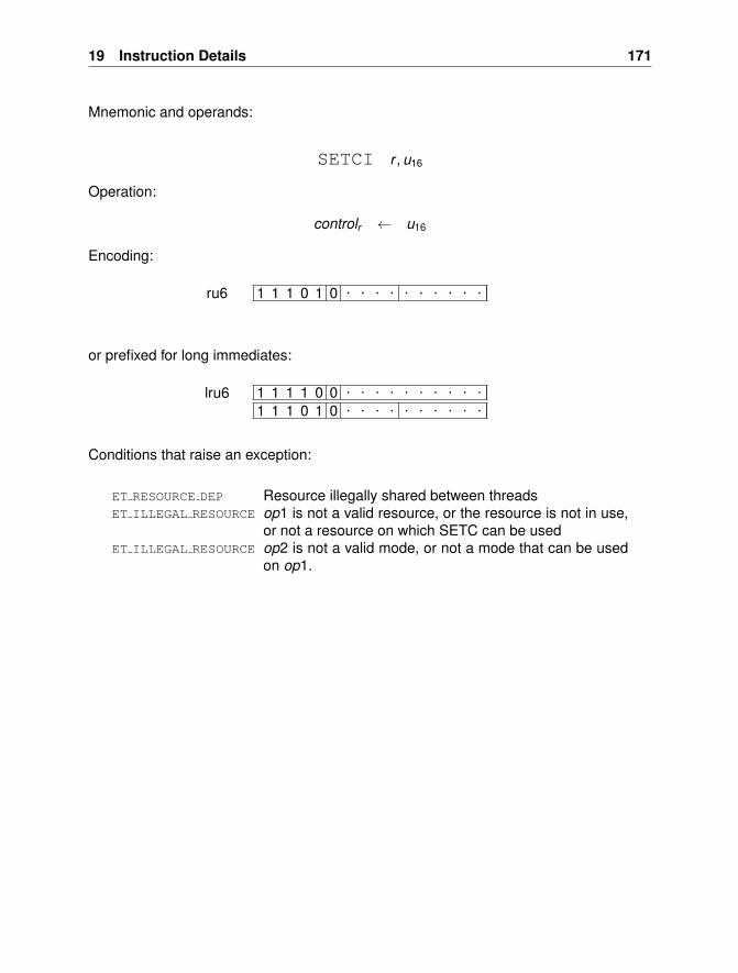
19 Instruction Details 171
Mnemonic and operands:
SETCI r , u16
Operation:
controlr ← u16
Encoding:
1 1 1 0 1 0 . . . . . . . . . .ru6
or prefixed for long immediates:
1 1 1 1 0 0 . . . . . . . . . .
1 1 1 0 1 0 . . . . . . . . . .lru6
Conditions that raise an exception:
ET RESOURCE DEP Resource illegally shared between threadsET ILLEGAL RESOURCE op1 is not a valid resource, or the resource is not in use,
or not a resource on which SETC can be usedET ILLEGAL RESOURCE op2 is not a valid mode, or not a mode that can be used
on op1.
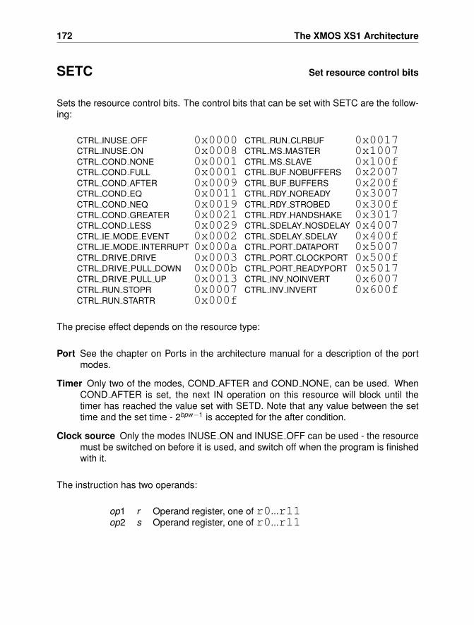
172 The XMOS XS1 Architecture
SETC Set resource control bits
Sets the resource control bits. The control bits that can be set with SETC are the follow-ing:
CTRL INUSE OFF 0x0000 CTRL RUN CLRBUF 0x0017CTRL INUSE ON 0x0008 CTRL MS MASTER 0x1007CTRL COND NONE 0x0001 CTRL MS SLAVE 0x100fCTRL COND FULL 0x0001 CTRL BUF NOBUFFERS 0x2007CTRL COND AFTER 0x0009 CTRL BUF BUFFERS 0x200fCTRL COND EQ 0x0011 CTRL RDY NOREADY 0x3007CTRL COND NEQ 0x0019 CTRL RDY STROBED 0x300fCTRL COND GREATER 0x0021 CTRL RDY HANDSHAKE 0x3017CTRL COND LESS 0x0029 CTRL SDELAY NOSDELAY 0x4007CTRL IE MODE EVENT 0x0002 CTRL SDELAY SDELAY 0x400fCTRL IE MODE INTERRUPT 0x000a CTRL PORT DATAPORT 0x5007CTRL DRIVE DRIVE 0x0003 CTRL PORT CLOCKPORT 0x500fCTRL DRIVE PULL DOWN 0x000b CTRL PORT READYPORT 0x5017CTRL DRIVE PULL UP 0x0013 CTRL INV NOINVERT 0x6007CTRL RUN STOPR 0x0007 CTRL INV INVERT 0x600fCTRL RUN STARTR 0x000f
The precise effect depends on the resource type:
Port See the chapter on Ports in the architecture manual for a description of the portmodes.
Timer Only two of the modes, COND AFTER and COND NONE, can be used. WhenCOND AFTER is set, the next IN operation on this resource will block until thetimer has reached the value set with SETD. Note that any value between the settime and the set time - 2bpw−1 is accepted for the after condition.
Clock source Only the modes INUSE ON and INUSE OFF can be used - the resourcemust be switched on before it is used, and switch off when the program is finishedwith it.
The instruction has two operands:
op1 r Operand register, one of r0...r11op2 s Operand register, one of r0...r11
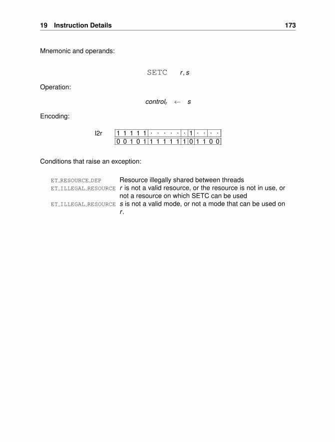
19 Instruction Details 173
Mnemonic and operands:
SETC r , s
Operation:
controlr ← s
Encoding:
1 1 1 1 1 . . . . . . 1 . . . .0 0 1 0 1 1 1 1 1 1 1 0 1 1 0 0
l2r
Conditions that raise an exception:
ET RESOURCE DEP Resource illegally shared between threadsET ILLEGAL RESOURCE r is not a valid resource, or the resource is not in use, or
not a resource on which SETC can be usedET ILLEGAL RESOURCE s is not a valid mode, or not a mode that can be used on
r .
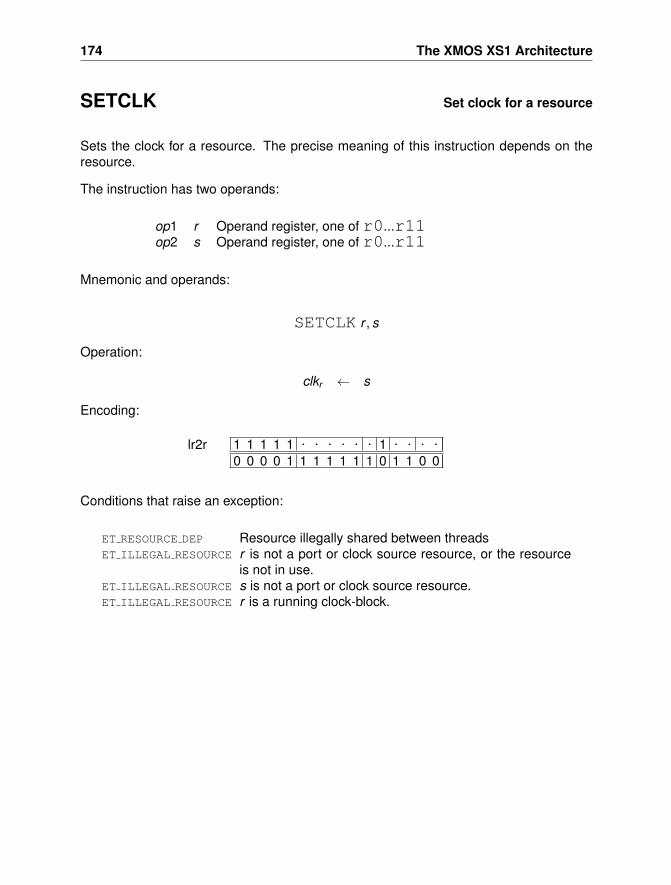
174 The XMOS XS1 Architecture
SETCLK Set clock for a resource
Sets the clock for a resource. The precise meaning of this instruction depends on theresource.
The instruction has two operands:
op1 r Operand register, one of r0...r11op2 s Operand register, one of r0...r11
Mnemonic and operands:
SETCLK r , s
Operation:
clkr ← s
Encoding:
1 1 1 1 1 . . . . . . 1 . . . .0 0 0 0 1 1 1 1 1 1 1 0 1 1 0 0
lr2r
Conditions that raise an exception:
ET RESOURCE DEP Resource illegally shared between threadsET ILLEGAL RESOURCE r is not a port or clock source resource, or the resource
is not in use.ET ILLEGAL RESOURCE s is not a port or clock source resource.ET ILLEGAL RESOURCE r is a running clock-block.
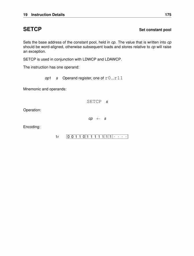
19 Instruction Details 175
SETCP Set constant pool
Sets the base address of the constant pool, held in cp. The value that is written into cpshould be word-aligned, otherwise subsequent loads and stores relative to cp will raisean exception.
SETCP is used in conjunction with LDWCP and LDAWCP.
The instruction has one operand:
op1 s Operand register, one of r0...r11
Mnemonic and operands:
SETCP s
Operation:
cp ← s
Encoding:
0 0 1 1 0 1 1 1 1 1 1 1 . . . .1r
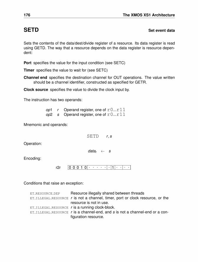
176 The XMOS XS1 Architecture
SETD Set event data
Sets the contents of the data/dest/divide register of a resource. Its data register is readusing GETD. The way that a resource depends on the data register is resource depen-dent:
Port specifies the value for the input condition (see SETC)
Timer specifies the value to wait for (see SETC)
Channel end specifies the destination channel for OUT operations. The value writtenshould be a channel identifier, constructed as specified for GETR.
Clock source specifies the value to divide the clock input by.
The instruction has two operands:
op1 r Operand register, one of r0...r11op2 s Operand register, one of r0...r11
Mnemonic and operands:
SETD r , s
Operation:
datar ← s
Encoding:
0 0 0 1 0 . . . . . . 1 . . . .r2r
Conditions that raise an exception:
ET RESOURCE DEP Resource illegally shared between threadsET ILLEGAL RESOURCE r is not a channel, timer, port or clock resource, or the
resource is not in use.ET ILLEGAL RESOURCE r is a running clock-block.ET ILLEGAL RESOURCE r is a channel-end, and s is not a channel-end or a con-
figuration resource.
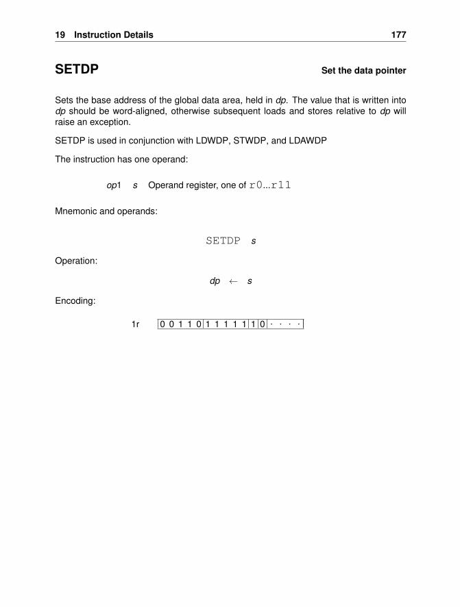
19 Instruction Details 177
SETDP Set the data pointer
Sets the base address of the global data area, held in dp. The value that is written intodp should be word-aligned, otherwise subsequent loads and stores relative to dp willraise an exception.
SETDP is used in conjunction with LDWDP, STWDP, and LDAWDP
The instruction has one operand:
op1 s Operand register, one of r0...r11
Mnemonic and operands:
SETDP s
Operation:
dp ← s
Encoding:
0 0 1 1 0 1 1 1 1 1 1 0 . . . .1r
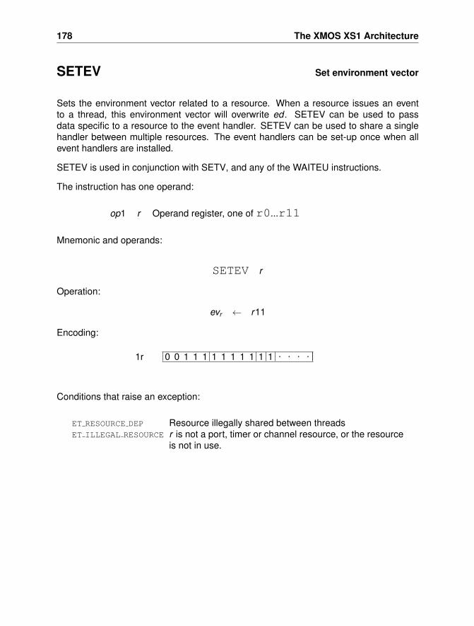
178 The XMOS XS1 Architecture
SETEV Set environment vector
Sets the environment vector related to a resource. When a resource issues an eventto a thread, this environment vector will overwrite ed . SETEV can be used to passdata specific to a resource to the event handler. SETEV can be used to share a singlehandler between multiple resources. The event handlers can be set-up once when allevent handlers are installed.
SETEV is used in conjunction with SETV, and any of the WAITEU instructions.
The instruction has one operand:
op1 r Operand register, one of r0...r11
Mnemonic and operands:
SETEV r
Operation:
evr ← r11
Encoding:
0 0 1 1 1 1 1 1 1 1 1 1 . . . .1r
Conditions that raise an exception:
ET RESOURCE DEP Resource illegally shared between threadsET ILLEGAL RESOURCE r is not a port, timer or channel resource, or the resource
is not in use.
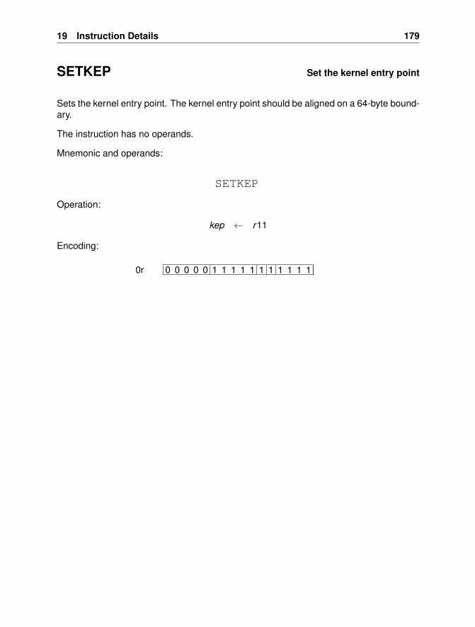
19 Instruction Details 179
SETKEP Set the kernel entry point
Sets the kernel entry point. The kernel entry point should be aligned on a 64-byte bound-ary.
The instruction has no operands.
Mnemonic and operands:
SETKEP
Operation:
kep ← r11
Encoding:
0 0 0 0 0 1 1 1 1 1 1 1 1 1 1 10r
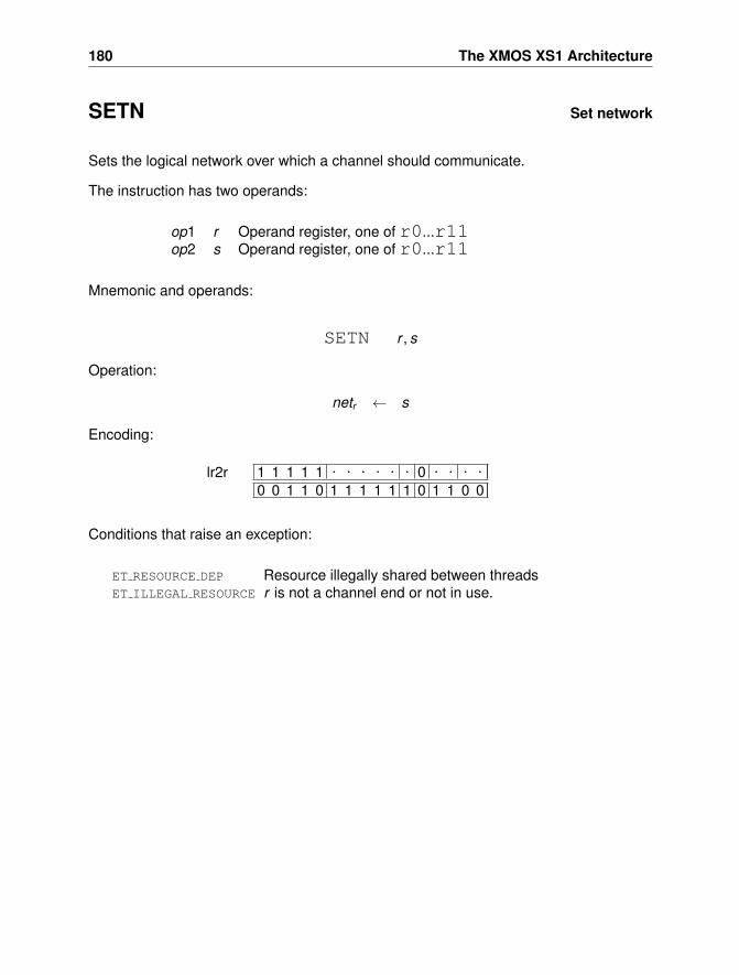
180 The XMOS XS1 Architecture
SETN Set network
Sets the logical network over which a channel should communicate.
The instruction has two operands:
op1 r Operand register, one of r0...r11op2 s Operand register, one of r0...r11
Mnemonic and operands:
SETN r , s
Operation:
netr ← s
Encoding:
1 1 1 1 1 . . . . . . 0 . . . .0 0 1 1 0 1 1 1 1 1 1 0 1 1 0 0
lr2r
Conditions that raise an exception:
ET RESOURCE DEP Resource illegally shared between threadsET ILLEGAL RESOURCE r is not a channel end or not in use.
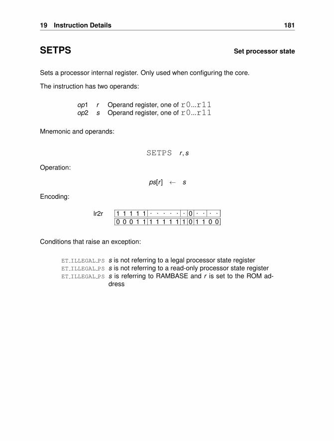
19 Instruction Details 181
SETPS Set processor state
Sets a processor internal register. Only used when configuring the core.
The instruction has two operands:
op1 r Operand register, one of r0...r11op2 s Operand register, one of r0...r11
Mnemonic and operands:
SETPS r , s
Operation:
ps[r ] ← s
Encoding:
1 1 1 1 1 . . . . . . 0 . . . .0 0 0 1 1 1 1 1 1 1 1 0 1 1 0 0
lr2r
Conditions that raise an exception:
ET ILLEGAL PS s is not referring to a legal processor state registerET ILLEGAL PS s is not referring to a read-only processor state registerET ILLEGAL PS s is referring to RAMBASE and r is set to the ROM ad-
dress
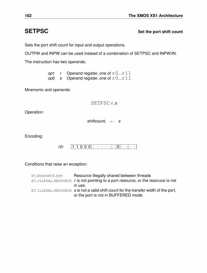
182 The XMOS XS1 Architecture
SETPSC Set the port shift count
Sets the port shift count for input and output operations.
OUTPW and INPW can be used instead of a combination of SETPSC and INPW/IN.
The instruction has two operands:
op1 r Operand register, one of r0...r11op2 s Operand register, one of r0...r11
Mnemonic and operands:
SETPSC r , s
Operation:
shiftcountr ← s
Encoding:
1 1 0 0 0 . . . . . . 0 . . . .r2r
Conditions that raise an exception:
ET RESOURCE DEP Resource illegally shared between threadsET ILLEGAL RESOURCE r is not pointing to a port resource, or the resoruce is not
in use.ET ILLEGAL RESOURCE s is not a valid shift count for the transfer width of the port,
or the port is not in BUFFERED mode.
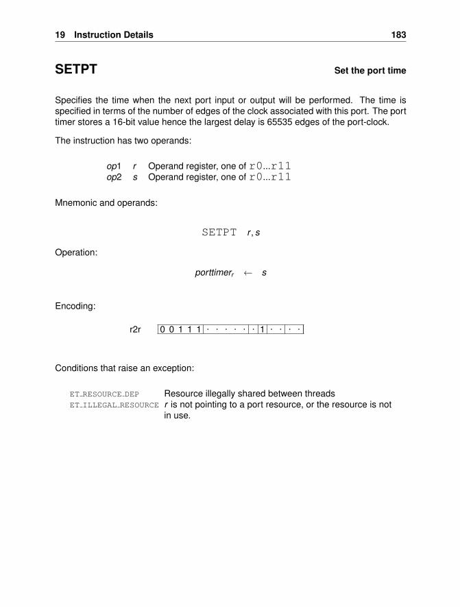
19 Instruction Details 183
SETPT Set the port time
Specifies the time when the next port input or output will be performed. The time isspecified in terms of the number of edges of the clock associated with this port. The porttimer stores a 16-bit value hence the largest delay is 65535 edges of the port-clock.
The instruction has two operands:
op1 r Operand register, one of r0...r11op2 s Operand register, one of r0...r11
Mnemonic and operands:
SETPT r , s
Operation:
porttimerr ← s
Encoding:
0 0 1 1 1 . . . . . . 1 . . . .r2r
Conditions that raise an exception:
ET RESOURCE DEP Resource illegally shared between threadsET ILLEGAL RESOURCE r is not pointing to a port resource, or the resource is not
in use.
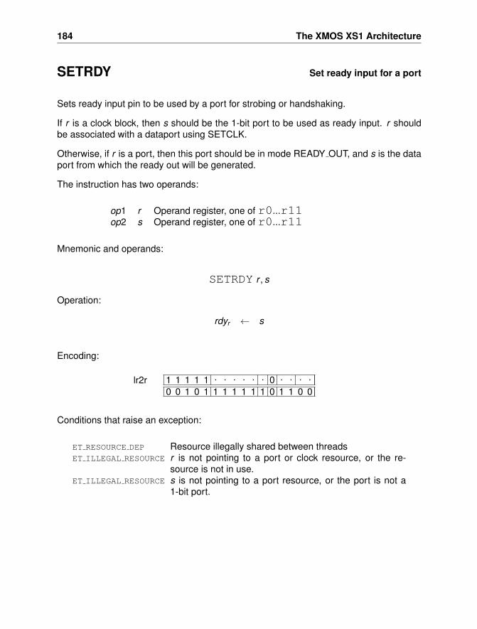
184 The XMOS XS1 Architecture
SETRDY Set ready input for a port
Sets ready input pin to be used by a port for strobing or handshaking.
If r is a clock block, then s should be the 1-bit port to be used as ready input. r shouldbe associated with a dataport using SETCLK.
Otherwise, if r is a port, then this port should be in mode READY OUT, and s is the dataport from which the ready out will be generated.
The instruction has two operands:
op1 r Operand register, one of r0...r11op2 s Operand register, one of r0...r11
Mnemonic and operands:
SETRDY r , s
Operation:
rdyr ← s
Encoding:
1 1 1 1 1 . . . . . . 0 . . . .0 0 1 0 1 1 1 1 1 1 1 0 1 1 0 0
lr2r
Conditions that raise an exception:
ET RESOURCE DEP Resource illegally shared between threadsET ILLEGAL RESOURCE r is not pointing to a port or clock resource, or the re-
source is not in use.ET ILLEGAL RESOURCE s is not pointing to a port resource, or the port is not a
1-bit port.
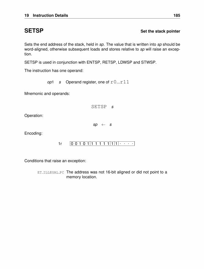
19 Instruction Details 185
SETSP Set the stack pointer
Sets the end address of the stack, held in sp. The value that is written into sp should beword-aligned, otherwise subsequent loads and stores relative to sp will raise an excep-tion.
SETSP is used in conjunction with ENTSP, RETSP, LDWSP and STWSP.
The instruction has one operand:
op1 s Operand register, one of r0...r11
Mnemonic and operands:
SETSP s
Operation:
sp ← s
Encoding:
0 0 1 0 1 1 1 1 1 1 1 1 . . . .1r
Conditions that raise an exception:
ET ILLEGAL PC The address was not 16-bit aligned or did not point to amemory location.
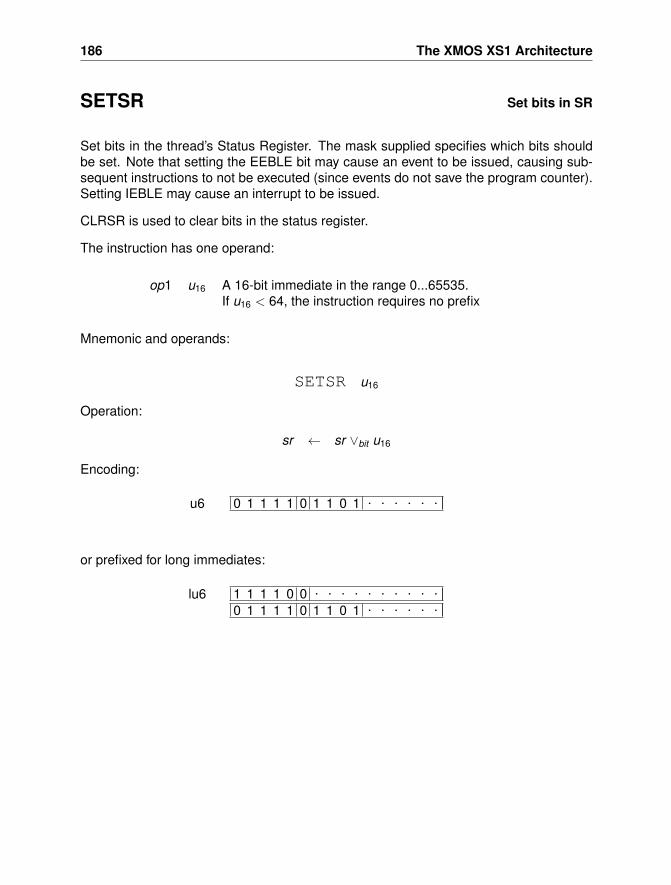
186 The XMOS XS1 Architecture
SETSR Set bits in SR
Set bits in the thread’s Status Register. The mask supplied specifies which bits shouldbe set. Note that setting the EEBLE bit may cause an event to be issued, causing sub-sequent instructions to not be executed (since events do not save the program counter).Setting IEBLE may cause an interrupt to be issued.
CLRSR is used to clear bits in the status register.
The instruction has one operand:
op1 u16 A 16-bit immediate in the range 0...65535.If u16 < 64, the instruction requires no prefix
Mnemonic and operands:
SETSR u16
Operation:
sr ← sr ∨bit u16
Encoding:
0 1 1 1 1 0 1 1 0 1 . . . . . .u6
or prefixed for long immediates:
1 1 1 1 0 0 . . . . . . . . . .0 1 1 1 1 0 1 1 0 1 . . . . . .
lu6
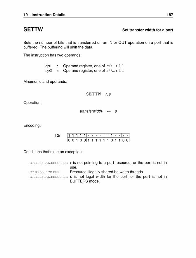
19 Instruction Details 187
SETTW Set transfer width for a port
Sets the number of bits that is transferred on an IN or OUT operation on a port that isbuffered. The buffering will shift the data.
The instruction has two operands:
op1 r Operand register, one of r0...r11op2 s Operand register, one of r0...r11
Mnemonic and operands:
SETTW r , s
Operation:
transferwidthr ← s
Encoding:
1 1 1 1 1 . . . . . . 1 . . . .0 0 1 0 0 1 1 1 1 1 1 0 1 1 0 0
lr2r
Conditions that raise an exception:
ET ILLEGAL RESOURCE r is not pointing to a port resource, or the port is not inuse.
ET RESOURCE DEP Resource illegally shared between threadsET ILLEGAL RESOURCE s is not legal width for the port, or the port is not in
BUFFERS mode.
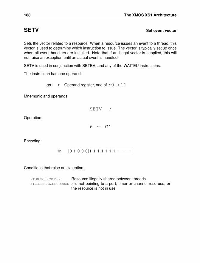
188 The XMOS XS1 Architecture
SETV Set event vector
Sets the vector related to a resource. When a resource issues an event to a thread, thisvector is used to determine which instruction to issue. The vector is typically set up oncewhen all event handlers are installed. Note that if an illegal vector is supplied, this willnot raise an exception until an actual event is handled.
SETV is used in conjunction with SETEV, and any of the WAITEU instructions.
The instruction has one operand:
op1 r Operand register, one of r0...r11
Mnemonic and operands:
SETV r
Operation:
vr ← r11
Encoding:
0 1 0 0 0 1 1 1 1 1 1 1 . . . .1r
Conditions that raise an exception:
ET RESOURCE DEP Resource illegally shared between threadsET ILLEGAL RESOURCE r is not pointing to a port, timer or channel resoruce, or
the resource is not in use.
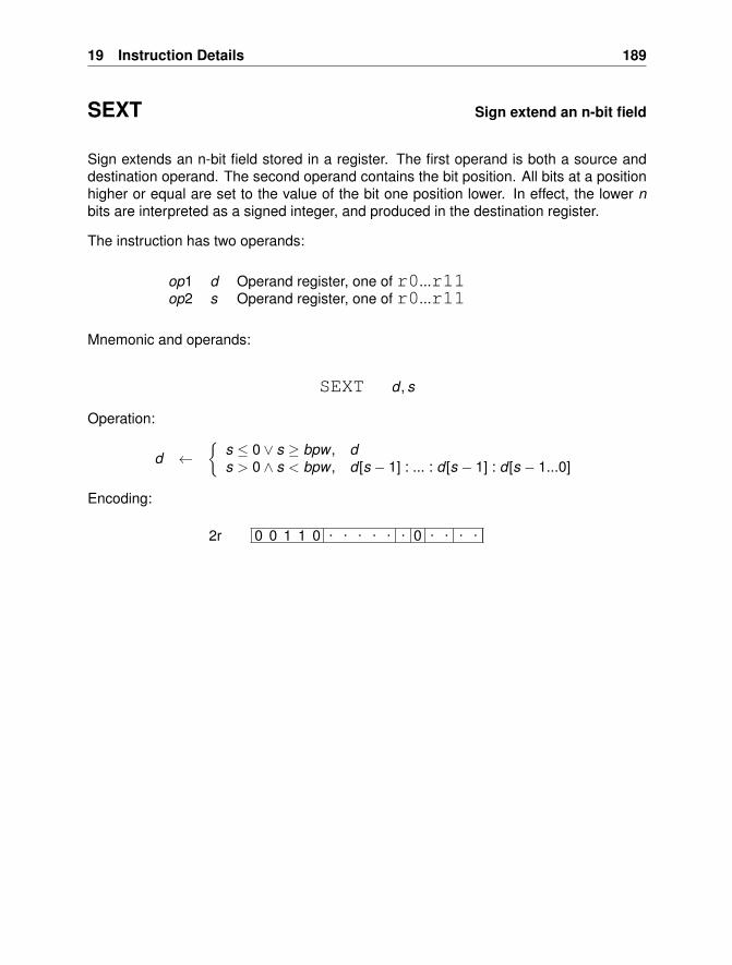
19 Instruction Details 189
SEXT Sign extend an n-bit field
Sign extends an n-bit field stored in a register. The first operand is both a source anddestination operand. The second operand contains the bit position. All bits at a positionhigher or equal are set to the value of the bit one position lower. In effect, the lower nbits are interpreted as a signed integer, and produced in the destination register.
The instruction has two operands:
op1 d Operand register, one of r0...r11op2 s Operand register, one of r0...r11
Mnemonic and operands:
SEXT d , s
Operation:
d ←{
s ≤ 0 ∨ s ≥ bpw , ds > 0 ∧ s < bpw , d [s − 1] : ... : d [s − 1] : d [s − 1...0]
Encoding:
0 0 1 1 0 . . . . . . 0 . . . .2r
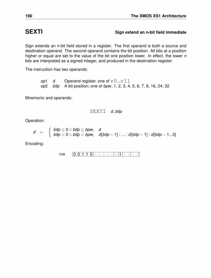
190 The XMOS XS1 Architecture
SEXTI Sign extend an n-bit field immediate
Sign extends an n-bit field stored in a register. The first operand is both a source anddestination operand. The second operand contains the bit position. All bits at a positionhigher or equal are set to the value of the bit one position lower. In effect, the lower nbits are interpreted as a signed integer, and produced in the destination register.
The instruction has two operands:
op1 d Operand register, one of r0...r11op2 bitp A bit position; one of bpw , 1, 2, 3, 4, 5, 6, 7, 8, 16, 24, 32
Mnemonic and operands:
SEXTI d , bitp
Operation:
d ←{
bitp ≤ 0 ∨ bitp ≥ bpw , dbitp > 0 ∧ bitp < bpw , d [bitp − 1] : ... : d [bitp − 1] : d [bitp − 1...0]
Encoding:
0 0 1 1 0 . . . . . . 1 . . . .rus
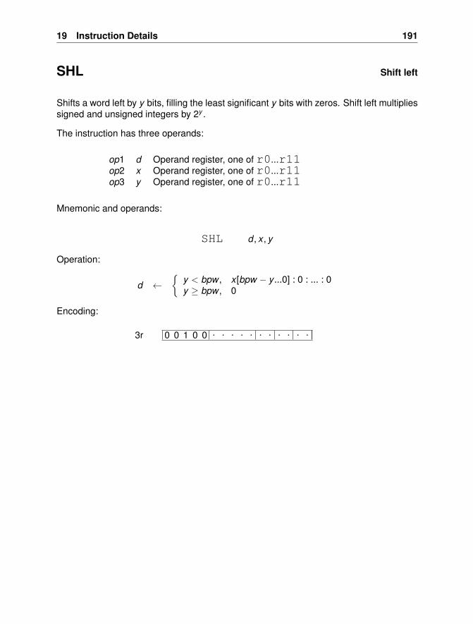
19 Instruction Details 191
SHL Shift left
Shifts a word left by y bits, filling the least significant y bits with zeros. Shift left multipliessigned and unsigned integers by 2y .
The instruction has three operands:
op1 d Operand register, one of r0...r11op2 x Operand register, one of r0...r11op3 y Operand register, one of r0...r11
Mnemonic and operands:
SHL d , x , y
Operation:
d ←{
y < bpw , x [bpw − y ...0] : 0 : ... : 0y ≥ bpw , 0
Encoding:
0 0 1 0 0 . . . . . . . . . . .3r
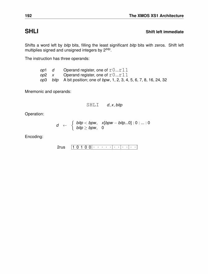
192 The XMOS XS1 Architecture
SHLI Shift left immediate
Shifts a word left by bitp bits, filling the least significant bitp bits with zeros. Shift leftmultiplies signed and unsigned integers by 2bitp.
The instruction has three operands:
op1 d Operand register, one of r0...r11op2 x Operand register, one of r0...r11op3 bitp A bit position; one of bpw , 1, 2, 3, 4, 5, 6, 7, 8, 16, 24, 32
Mnemonic and operands:
SHLI d , x , bitp
Operation:
d ←{
bitp < bpw , x [bpw − bitp...0] : 0 : ... : 0bitp ≥ bpw , 0
Encoding:
1 0 1 0 0 . . . . . . . . . . .2rus
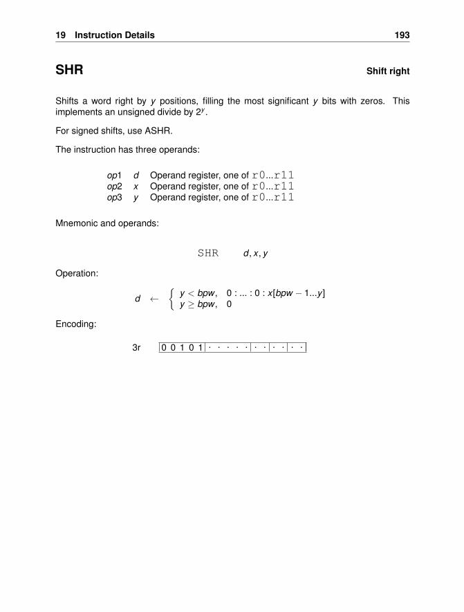
19 Instruction Details 193
SHR Shift right
Shifts a word right by y positions, filling the most significant y bits with zeros. Thisimplements an unsigned divide by 2y .
For signed shifts, use ASHR.
The instruction has three operands:
op1 d Operand register, one of r0...r11op2 x Operand register, one of r0...r11op3 y Operand register, one of r0...r11
Mnemonic and operands:
SHR d , x , y
Operation:
d ←{
y < bpw , 0 : ... : 0 : x [bpw − 1...y ]y ≥ bpw , 0
Encoding:
0 0 1 0 1 . . . . . . . . . . .3r
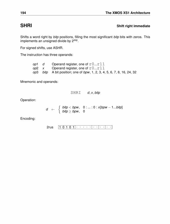
194 The XMOS XS1 Architecture
SHRI Shift right immediate
Shifts a word right by bitp positions, filling the most significant bitp bits with zeros. Thisimplements an unsigned divide by 2bitp.
For signed shifts, use ASHR.
The instruction has three operands:
op1 d Operand register, one of r0...r11op2 x Operand register, one of r0...r11op3 bitp A bit position; one of bpw , 1, 2, 3, 4, 5, 6, 7, 8, 16, 24, 32
Mnemonic and operands:
SHRI d , x , bitp
Operation:
d ←{
bitp < bpw , 0 : ... : 0 : x [bpw − 1...bitp]bitp ≥ bpw , 0
Encoding:
1 0 1 0 1 . . . . . . . . . . .2rus
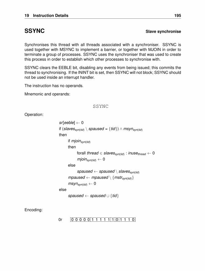
19 Instruction Details 195
SSYNC Slave synchronise
Synchronises this thread with all threads associated with a synchroniser. SSYNC isused together with MSYNC to implement a barrier, or together with MJOIN in order toterminate a group of processes. SSYNC uses the synchroniser that was used to createthis process in order to establish which other processes to synchronise with.
SSYNC clears the EEBLE bit, disabling any events from being issued; this commits thethread to synchronising. If the ININT bit is set, then SSYNC will not block; SSYNC shouldnot be used inside an interrupt handler.
The instruction has no operands.
Mnemonic and operands:
SSYNC
Operation:
sr [eeble]← 0if (slavessyn(tid) \ spaused = {tid}) ∧msynsyn(tid)
thenif mjoinsyn(tid)
thenforall thread ∈ slavessyn(tid) : inusethread ← 0mjoinsyn(tid) ← 0
elsespaused ← spaused \ slavessyn(tid)
mpaused ← mpaused \ {mstrsyn(tid)}msynsyn(tid) ← 0
elsespaused ← spaused ∪ {tid}
Encoding:
0 0 0 0 0 1 1 1 1 1 1 0 1 1 1 00r
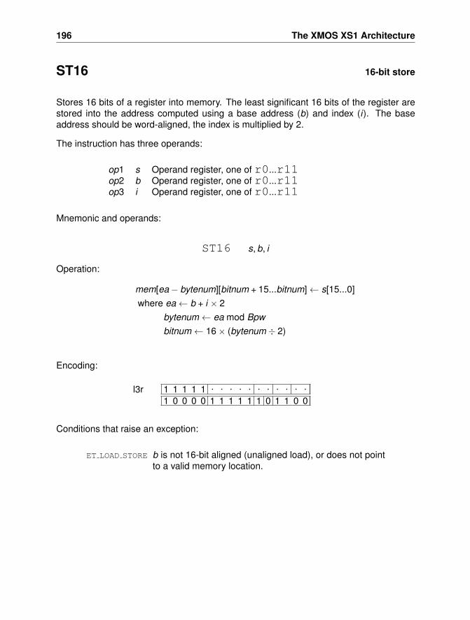
196 The XMOS XS1 Architecture
ST16 16-bit store
Stores 16 bits of a register into memory. The least significant 16 bits of the register arestored into the address computed using a base address (b) and index (i). The baseaddress should be word-aligned, the index is multiplied by 2.
The instruction has three operands:
op1 s Operand register, one of r0...r11op2 b Operand register, one of r0...r11op3 i Operand register, one of r0...r11
Mnemonic and operands:
ST16 s, b, i
Operation:
mem[ea− bytenum][bitnum + 15...bitnum]← s[15...0]where ea← b + i × 2
bytenum← ea mod Bpwbitnum← 16× (bytenum ÷ 2)
Encoding:
1 1 1 1 1 . . . . . . . . . . .
1 0 0 0 0 1 1 1 1 1 1 0 1 1 0 0l3r
Conditions that raise an exception:
ET LOAD STORE b is not 16-bit aligned (unaligned load), or does not pointto a valid memory location.
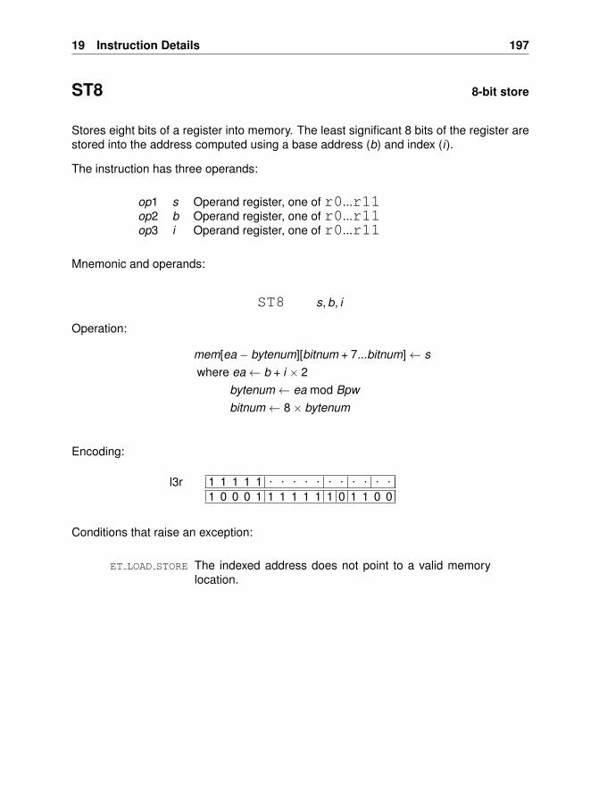
19 Instruction Details 197
ST8 8-bit store
Stores eight bits of a register into memory. The least significant 8 bits of the register arestored into the address computed using a base address (b) and index (i).
The instruction has three operands:
op1 s Operand register, one of r0...r11op2 b Operand register, one of r0...r11op3 i Operand register, one of r0...r11
Mnemonic and operands:
ST8 s, b, i
Operation:
mem[ea− bytenum][bitnum + 7...bitnum]← swhere ea← b + i × 2
bytenum← ea mod Bpwbitnum← 8× bytenum
Encoding:
1 1 1 1 1 . . . . . . . . . . .
1 0 0 0 1 1 1 1 1 1 1 0 1 1 0 0l3r
Conditions that raise an exception:
ET LOAD STORE The indexed address does not point to a valid memorylocation.
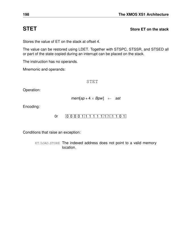
198 The XMOS XS1 Architecture
STET Store ET on the stack
Stores the value of ET on the stack at offset 4.
The value can be restored using LDET. Together with STSPC, STSSR, and STSED allor part of the state copied during an interrupt can be placed on the stack.
The instruction has no operands.
Mnemonic and operands:
STET
Operation:
mem[sp + 4× Bpw ] ← set
Encoding:
0 0 0 0 1 1 1 1 1 1 1 1 1 1 0 10r
Conditions that raise an exception:
ET LOAD STORE The indexed address does not point to a valid memorylocation.

19 Instruction Details 199
STSED Store SED on the stack
Stores the value of SED on the stack at offset 3.
The value can be restored using LDSED. Together with STSPC, STSSR, and STET allor part of the state copied during an interrupt can be placed on the stack.
The instruction has no operands.
Mnemonic and operands:
STSED
Operation:
mem[sp + 3× Bpw ] ← sed
Encoding:
0 0 0 0 1 1 1 1 1 1 1 1 1 1 0 00r
Conditions that raise an exception:
ET LOAD STORE The indexed address does not point to a valid memorylocation.
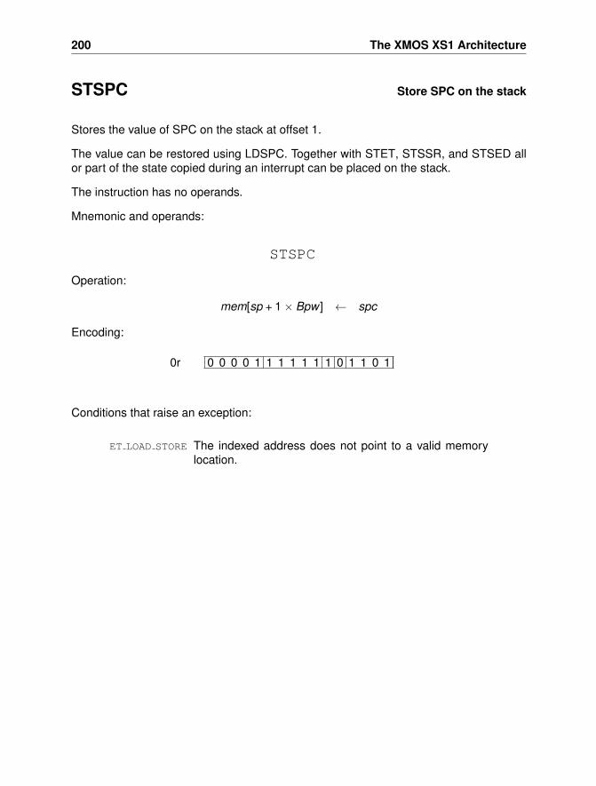
200 The XMOS XS1 Architecture
STSPC Store SPC on the stack
Stores the value of SPC on the stack at offset 1.
The value can be restored using LDSPC. Together with STET, STSSR, and STSED allor part of the state copied during an interrupt can be placed on the stack.
The instruction has no operands.
Mnemonic and operands:
STSPC
Operation:
mem[sp + 1× Bpw ] ← spc
Encoding:
0 0 0 0 1 1 1 1 1 1 1 0 1 1 0 10r
Conditions that raise an exception:
ET LOAD STORE The indexed address does not point to a valid memorylocation.

19 Instruction Details 201
STSSR Store the SSR to the stack
Stores the value of SSR on the stack at offset 2.
The value can be restored using LDSSR. Together with STET, STSPC, and STSED allor part of the state copied during an interrupt can be placed on the stack.
The instruction has no operands.
Mnemonic and operands:
STSSR
Operation:
mem[sp + 2× Bpw ] ← ssr
Encoding:
0 0 0 0 1 1 1 1 1 1 1 0 1 1 1 10r
Conditions that raise an exception:
ET LOAD STORE The indexed address does not point to a valid memorylocation.
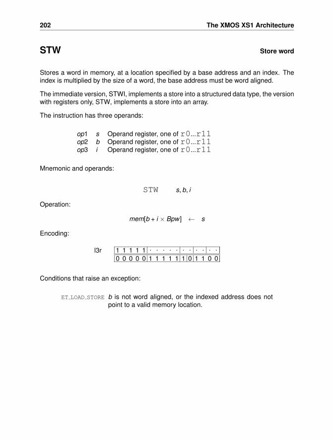
202 The XMOS XS1 Architecture
STW Store word
Stores a word in memory, at a location specified by a base address and an index. Theindex is multiplied by the size of a word, the base address must be word aligned.
The immediate version, STWI, implements a store into a structured data type, the versionwith registers only, STW, implements a store into an array.
The instruction has three operands:
op1 s Operand register, one of r0...r11op2 b Operand register, one of r0...r11op3 i Operand register, one of r0...r11
Mnemonic and operands:
STW s, b, i
Operation:
mem[b + i × Bpw ] ← s
Encoding:
1 1 1 1 1 . . . . . . . . . . .0 0 0 0 0 1 1 1 1 1 1 0 1 1 0 0
l3r
Conditions that raise an exception:
ET LOAD STORE b is not word aligned, or the indexed address does notpoint to a valid memory location.
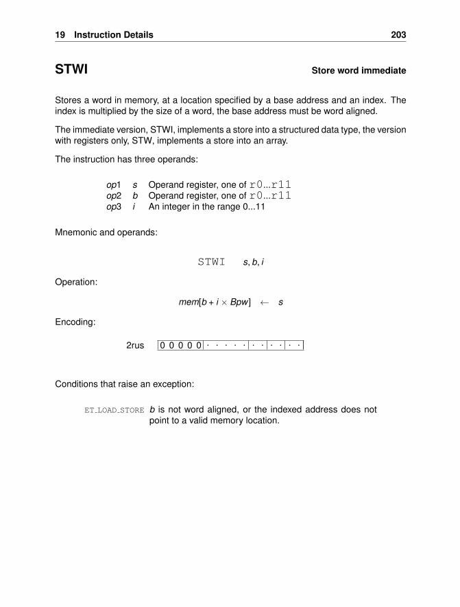
19 Instruction Details 203
STWI Store word immediate
Stores a word in memory, at a location specified by a base address and an index. Theindex is multiplied by the size of a word, the base address must be word aligned.
The immediate version, STWI, implements a store into a structured data type, the versionwith registers only, STW, implements a store into an array.
The instruction has three operands:
op1 s Operand register, one of r0...r11op2 b Operand register, one of r0...r11op3 i An integer in the range 0...11
Mnemonic and operands:
STWI s, b, i
Operation:
mem[b + i × Bpw ] ← s
Encoding:
0 0 0 0 0 . . . . . . . . . . .2rus
Conditions that raise an exception:
ET LOAD STORE b is not word aligned, or the indexed address does notpoint to a valid memory location.
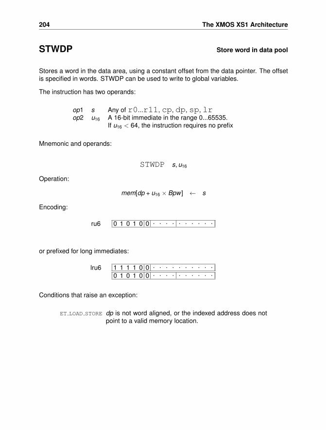
204 The XMOS XS1 Architecture
STWDP Store word in data pool
Stores a word in the data area, using a constant offset from the data pointer. The offsetis specified in words. STWDP can be used to write to global variables.
The instruction has two operands:
op1 s Any of r0...r11, cp, dp, sp, lrop2 u16 A 16-bit immediate in the range 0...65535.
If u16 < 64, the instruction requires no prefix
Mnemonic and operands:
STWDP s, u16
Operation:
mem[dp + u16 × Bpw ] ← s
Encoding:
0 1 0 1 0 0 . . . . . . . . . .ru6
or prefixed for long immediates:
1 1 1 1 0 0 . . . . . . . . . .0 1 0 1 0 0 . . . . . . . . . .
lru6
Conditions that raise an exception:
ET LOAD STORE dp is not word aligned, or the indexed address does notpoint to a valid memory location.
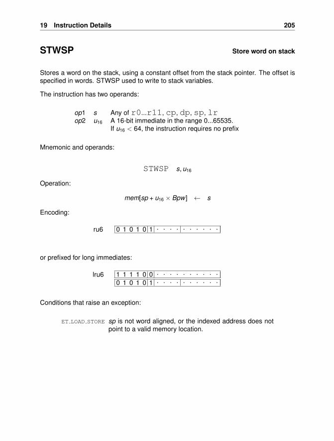
19 Instruction Details 205
STWSP Store word on stack
Stores a word on the stack, using a constant offset from the stack pointer. The offset isspecified in words. STWSP used to write to stack variables.
The instruction has two operands:
op1 s Any of r0...r11, cp, dp, sp, lrop2 u16 A 16-bit immediate in the range 0...65535.
If u16 < 64, the instruction requires no prefix
Mnemonic and operands:
STWSP s, u16
Operation:
mem[sp + u16 × Bpw ] ← s
Encoding:
0 1 0 1 0 1 . . . . . . . . . .ru6
or prefixed for long immediates:
1 1 1 1 0 0 . . . . . . . . . .0 1 0 1 0 1 . . . . . . . . . .
lru6
Conditions that raise an exception:
ET LOAD STORE sp is not word aligned, or the indexed address does notpoint to a valid memory location.
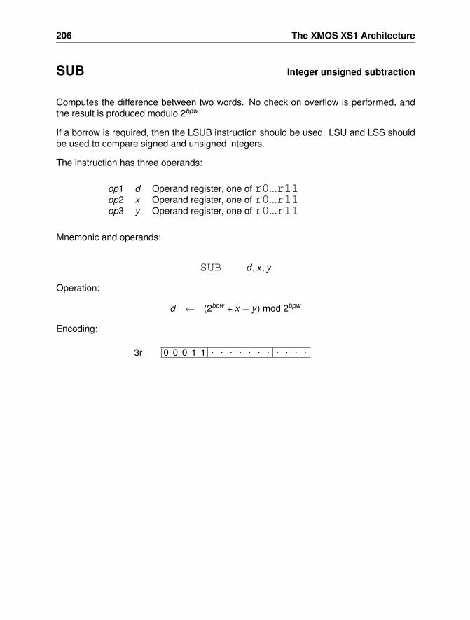
206 The XMOS XS1 Architecture
SUB Integer unsigned subtraction
Computes the difference between two words. No check on overflow is performed, andthe result is produced modulo 2bpw .
If a borrow is required, then the LSUB instruction should be used. LSU and LSS shouldbe used to compare signed and unsigned integers.
The instruction has three operands:
op1 d Operand register, one of r0...r11op2 x Operand register, one of r0...r11op3 y Operand register, one of r0...r11
Mnemonic and operands:
SUB d , x , y
Operation:
d ← (2bpw + x − y ) mod 2bpw
Encoding:
0 0 0 1 1 . . . . . . . . . . .3r
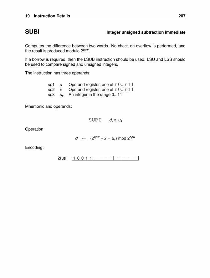
19 Instruction Details 207
SUBI Integer unsigned subtraction immediate
Computes the difference between two words. No check on overflow is performed, andthe result is produced modulo 2bpw .
If a borrow is required, then the LSUB instruction should be used. LSU and LSS shouldbe used to compare signed and unsigned integers.
The instruction has three operands:
op1 d Operand register, one of r0...r11op2 x Operand register, one of r0...r11op3 us An integer in the range 0...11
Mnemonic and operands:
SUBI d , x , us
Operation:
d ← (2bpw + x − us) mod 2bpw
Encoding:
1 0 0 1 1 . . . . . . . . . . .2rus
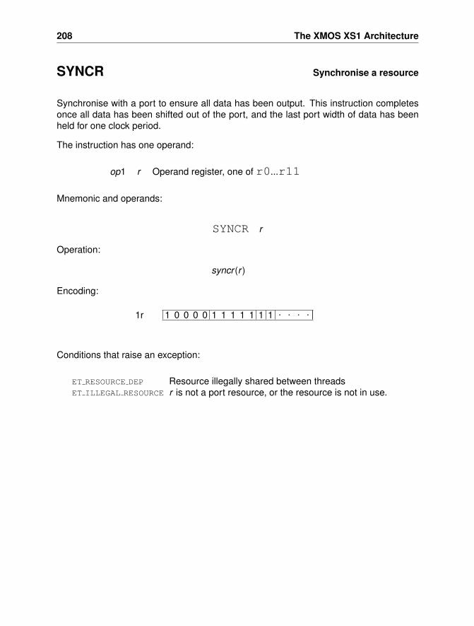
208 The XMOS XS1 Architecture
SYNCR Synchronise a resource
Synchronise with a port to ensure all data has been output. This instruction completesonce all data has been shifted out of the port, and the last port width of data has beenheld for one clock period.
The instruction has one operand:
op1 r Operand register, one of r0...r11
Mnemonic and operands:
SYNCR r
Operation:
syncr (r )
Encoding:
1 0 0 0 0 1 1 1 1 1 1 1 . . . .1r
Conditions that raise an exception:
ET RESOURCE DEP Resource illegally shared between threadsET ILLEGAL RESOURCE r is not a port resource, or the resource is not in use.
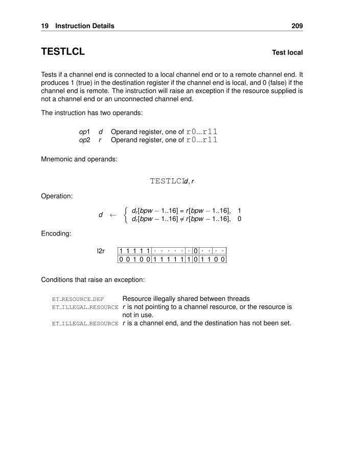
19 Instruction Details 209
TESTLCL Test local
Tests if a channel end is connected to a local channel end or to a remote channel end. Itproduces 1 (true) in the destination register if the channel end is local, and 0 (false) if thechannel end is remote. The instruction will raise an exception if the resource supplied isnot a channel end or an unconnected channel end.
The instruction has two operands:
op1 d Operand register, one of r0...r11op2 r Operand register, one of r0...r11
Mnemonic and operands:
TESTLCLd , r
Operation:
d ←{
dr [bpw − 1..16] = r [bpw − 1..16], 1dr [bpw − 1..16] 6= r [bpw − 1..16], 0
Encoding:
1 1 1 1 1 . . . . . . 0 . . . .0 0 1 0 0 1 1 1 1 1 1 0 1 1 0 0
l2r
Conditions that raise an exception:
ET RESOURCE DEP Resource illegally shared between threadsET ILLEGAL RESOURCE r is not pointing to a channel resource, or the resource is
not in use.ET ILLEGAL RESOURCE r is a channel end, and the destination has not been set.
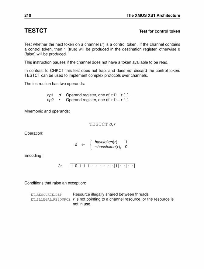
210 The XMOS XS1 Architecture
TESTCT Test for control token
Test whether the next token on a channel (r ) is a control token. If the channel containsa control token, then 1 (true) will be produced in the destination register, otherwise 0(false) will be produced.
This instruction pauses if the channel does not have a token available to be read.
In contrast to CHKCT this test does not trap, and does not discard the control token.TESTCT can be used to implement complex protocols over channels.
The instruction has two operands:
op1 d Operand register, one of r0...r11op2 r Operand register, one of r0...r11
Mnemonic and operands:
TESTCT d , r
Operation:
d ←{
hasctoken(r ), 1¬hasctoken(r ), 0
Encoding:
1 0 1 1 1 . . . . . . 1 . . . .2r
Conditions that raise an exception:
ET RESOURCE DEP Resource illegally shared between threadsET ILLEGAL RESOURCE r is not pointing to a channel resource, or the resource is
not in use.
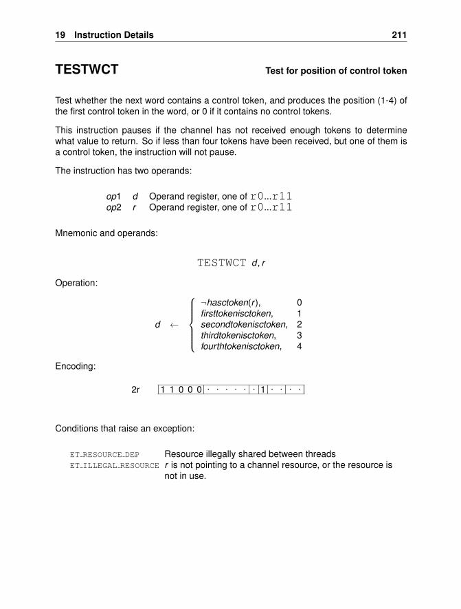
19 Instruction Details 211
TESTWCT Test for position of control token
Test whether the next word contains a control token, and produces the position (1-4) ofthe first control token in the word, or 0 if it contains no control tokens.
This instruction pauses if the channel has not received enough tokens to determinewhat value to return. So if less than four tokens have been received, but one of them isa control token, the instruction will not pause.
The instruction has two operands:
op1 d Operand register, one of r0...r11op2 r Operand register, one of r0...r11
Mnemonic and operands:
TESTWCT d , r
Operation:
d ←
¬hasctoken(r ), 0firsttokenisctoken, 1secondtokenisctoken, 2thirdtokenisctoken, 3fourthtokenisctoken, 4
Encoding:
1 1 0 0 0 . . . . . . 1 . . . .2r
Conditions that raise an exception:
ET RESOURCE DEP Resource illegally shared between threadsET ILLEGAL RESOURCE r is not pointing to a channel resource, or the resource is
not in use.
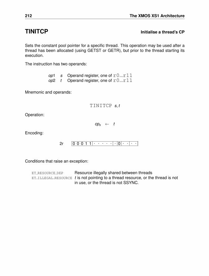
212 The XMOS XS1 Architecture
TINITCP Initialise a thread’s CP
Sets the constant pool pointer for a specific thread. This operation may be used after athread has been allocated (using GETST or GETR), but prior to the thread starting itsexecution.
The instruction has two operands:
op1 s Operand register, one of r0...r11op2 t Operand register, one of r0...r11
Mnemonic and operands:
TINITCP s, t
Operation:
cps ← t
Encoding:
0 0 0 1 1 . . . . . . 0 . . . .2r
Conditions that raise an exception:
ET RESOURCE DEP Resource illegally shared between threadsET ILLEGAL RESOURCE t is not pointing to a thread resource, or the thread is not
in use, or the thread is not SSYNC.
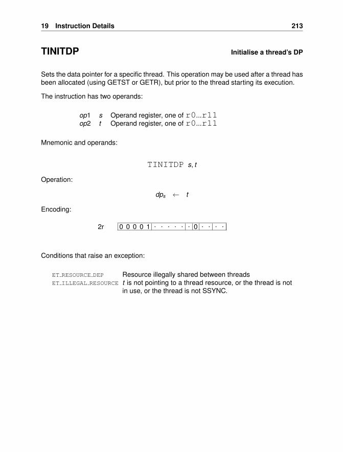
19 Instruction Details 213
TINITDP Initialise a thread’s DP
Sets the data pointer for a specific thread. This operation may be used after a thread hasbeen allocated (using GETST or GETR), but prior to the thread starting its execution.
The instruction has two operands:
op1 s Operand register, one of r0...r11op2 t Operand register, one of r0...r11
Mnemonic and operands:
TINITDP s, t
Operation:
dps ← t
Encoding:
0 0 0 0 1 . . . . . . 0 . . . .2r
Conditions that raise an exception:
ET RESOURCE DEP Resource illegally shared between threadsET ILLEGAL RESOURCE t is not pointing to a thread resource, or the thread is not
in use, or the thread is not SSYNC.
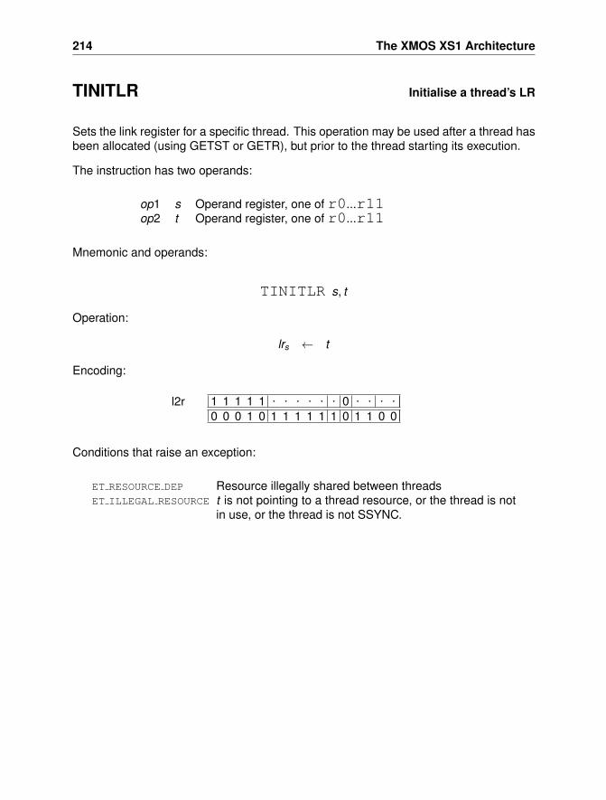
214 The XMOS XS1 Architecture
TINITLR Initialise a thread’s LR
Sets the link register for a specific thread. This operation may be used after a thread hasbeen allocated (using GETST or GETR), but prior to the thread starting its execution.
The instruction has two operands:
op1 s Operand register, one of r0...r11op2 t Operand register, one of r0...r11
Mnemonic and operands:
TINITLR s, t
Operation:
lrs ← t
Encoding:
1 1 1 1 1 . . . . . . 0 . . . .0 0 0 1 0 1 1 1 1 1 1 0 1 1 0 0
l2r
Conditions that raise an exception:
ET RESOURCE DEP Resource illegally shared between threadsET ILLEGAL RESOURCE t is not pointing to a thread resource, or the thread is not
in use, or the thread is not SSYNC.
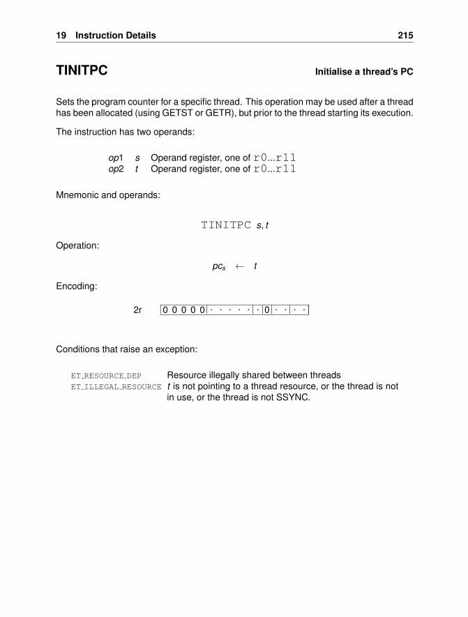
19 Instruction Details 215
TINITPC Initialise a thread’s PC
Sets the program counter for a specific thread. This operation may be used after a threadhas been allocated (using GETST or GETR), but prior to the thread starting its execution.
The instruction has two operands:
op1 s Operand register, one of r0...r11op2 t Operand register, one of r0...r11
Mnemonic and operands:
TINITPC s, t
Operation:
pcs ← t
Encoding:
0 0 0 0 0 . . . . . . 0 . . . .2r
Conditions that raise an exception:
ET RESOURCE DEP Resource illegally shared between threadsET ILLEGAL RESOURCE t is not pointing to a thread resource, or the thread is not
in use, or the thread is not SSYNC.
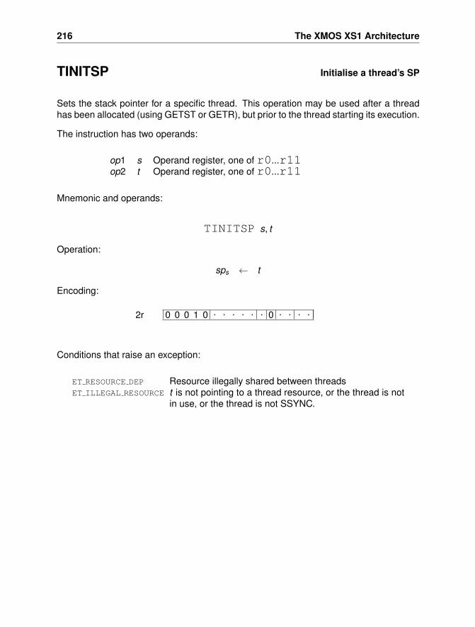
216 The XMOS XS1 Architecture
TINITSP Initialise a thread’s SP
Sets the stack pointer for a specific thread. This operation may be used after a threadhas been allocated (using GETST or GETR), but prior to the thread starting its execution.
The instruction has two operands:
op1 s Operand register, one of r0...r11op2 t Operand register, one of r0...r11
Mnemonic and operands:
TINITSP s, t
Operation:
sps ← t
Encoding:
0 0 0 1 0 . . . . . . 0 . . . .2r
Conditions that raise an exception:
ET RESOURCE DEP Resource illegally shared between threadsET ILLEGAL RESOURCE t is not pointing to a thread resource, or the thread is not
in use, or the thread is not SSYNC.
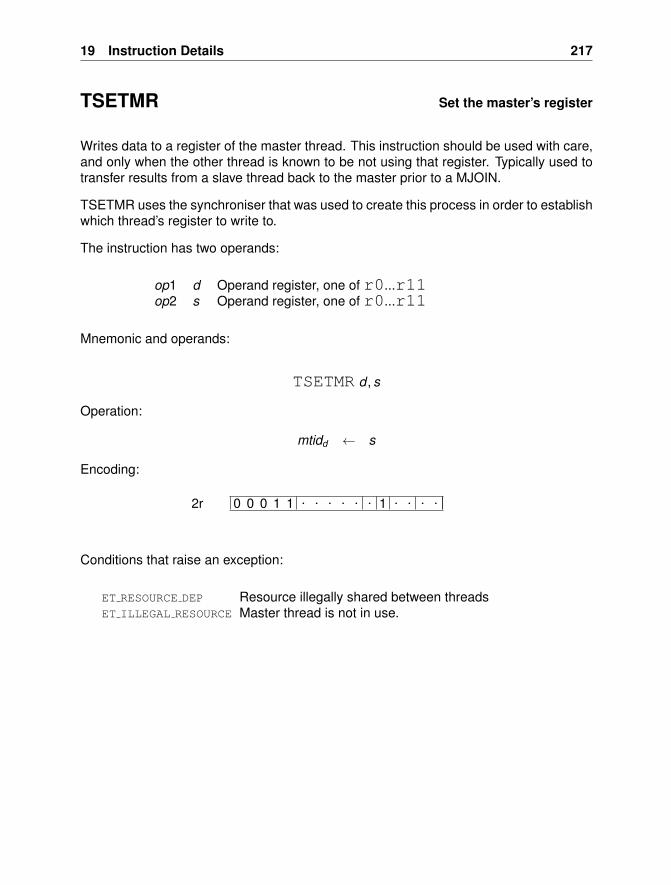
19 Instruction Details 217
TSETMR Set the master’s register
Writes data to a register of the master thread. This instruction should be used with care,and only when the other thread is known to be not using that register. Typically used totransfer results from a slave thread back to the master prior to a MJOIN.
TSETMR uses the synchroniser that was used to create this process in order to establishwhich thread’s register to write to.
The instruction has two operands:
op1 d Operand register, one of r0...r11op2 s Operand register, one of r0...r11
Mnemonic and operands:
TSETMR d , s
Operation:
mtidd ← s
Encoding:
0 0 0 1 1 . . . . . . 1 . . . .2r
Conditions that raise an exception:
ET RESOURCE DEP Resource illegally shared between threadsET ILLEGAL RESOURCE Master thread is not in use.
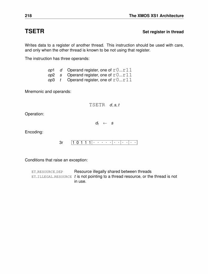
218 The XMOS XS1 Architecture
TSETR Set register in thread
Writes data to a register of another thread. This instruction should be used with care,and only when the other thread is known to be not using that register.
The instruction has three operands:
op1 d Operand register, one of r0...r11op2 s Operand register, one of r0...r11op3 t Operand register, one of r0...r11
Mnemonic and operands:
TSETR d , s, t
Operation:
dt ← s
Encoding:
1 0 1 1 1 . . . . . . . . . . .3r
Conditions that raise an exception:
ET RESOURCE DEP Resource illegally shared between threadsET ILLEGAL RESOURCE t is not pointing to a thread resource, or the thread is not
in use.
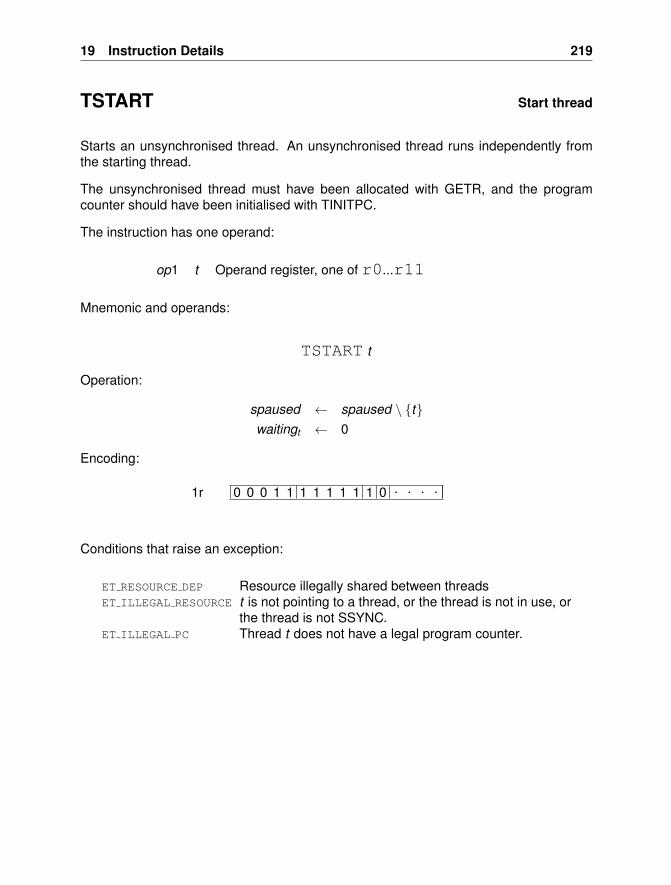
19 Instruction Details 219
TSTART Start thread
Starts an unsynchronised thread. An unsynchronised thread runs independently fromthe starting thread.
The unsynchronised thread must have been allocated with GETR, and the programcounter should have been initialised with TINITPC.
The instruction has one operand:
op1 t Operand register, one of r0...r11
Mnemonic and operands:
TSTART t
Operation:
spaused ← spaused \ {t}waitingt ← 0
Encoding:
0 0 0 1 1 1 1 1 1 1 1 0 . . . .1r
Conditions that raise an exception:
ET RESOURCE DEP Resource illegally shared between threadsET ILLEGAL RESOURCE t is not pointing to a thread, or the thread is not in use, or
the thread is not SSYNC.ET ILLEGAL PC Thread t does not have a legal program counter.
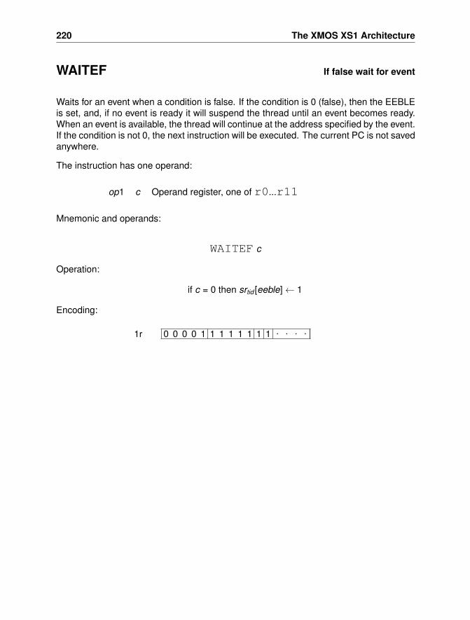
220 The XMOS XS1 Architecture
WAITEF If false wait for event
Waits for an event when a condition is false. If the condition is 0 (false), then the EEBLEis set, and, if no event is ready it will suspend the thread until an event becomes ready.When an event is available, the thread will continue at the address specified by the event.If the condition is not 0, the next instruction will be executed. The current PC is not savedanywhere.
The instruction has one operand:
op1 c Operand register, one of r0...r11
Mnemonic and operands:
WAITEF c
Operation:
if c = 0 then srtid [eeble]← 1
Encoding:
0 0 0 0 1 1 1 1 1 1 1 1 . . . .1r
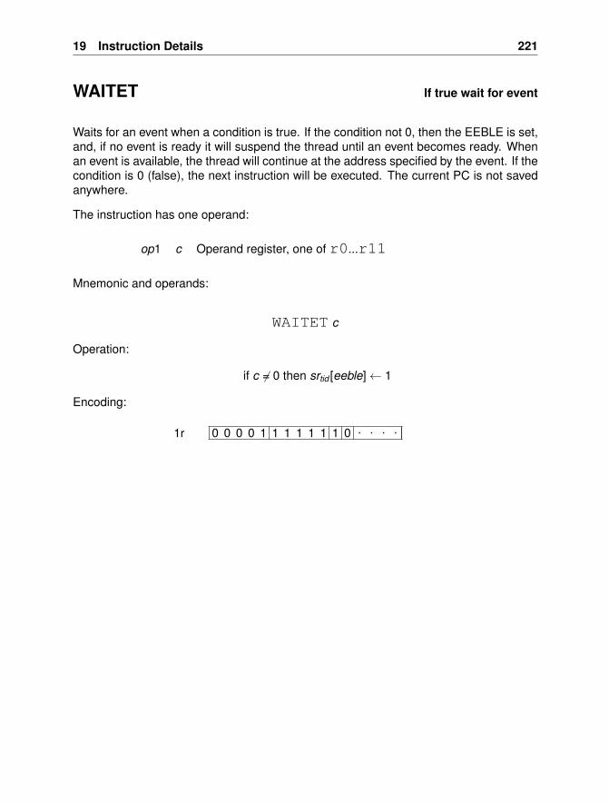
19 Instruction Details 221
WAITET If true wait for event
Waits for an event when a condition is true. If the condition not 0, then the EEBLE is set,and, if no event is ready it will suspend the thread until an event becomes ready. Whenan event is available, the thread will continue at the address specified by the event. If thecondition is 0 (false), the next instruction will be executed. The current PC is not savedanywhere.
The instruction has one operand:
op1 c Operand register, one of r0...r11
Mnemonic and operands:
WAITET c
Operation:
if c 6= 0 then srtid [eeble]← 1
Encoding:
0 0 0 0 1 1 1 1 1 1 1 0 . . . .1r
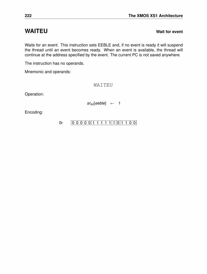
222 The XMOS XS1 Architecture
WAITEU Wait for event
Waits for an event. This instruction sets EEBLE and, if no event is ready it will suspendthe thread until an event becomes ready. When an event is available, the thread willcontinue at the address specified by the event. The current PC is not saved anywhere.
The instruction has no operands.
Mnemonic and operands:
WAITEU
Operation:
srtid [eeble] ← 1
Encoding:
0 0 0 0 0 1 1 1 1 1 1 0 1 1 0 00r
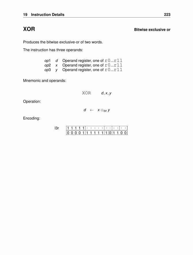
19 Instruction Details 223
XOR Bitwise exclusive or
Produces the bitwise exclusive-or of two words.
The instruction has three operands:
op1 d Operand register, one of r0...r11op2 x Operand register, one of r0...r11op3 y Operand register, one of r0...r11
Mnemonic and operands:
XOR d , x , y
Operation:
d ← x ⊕bit y
Encoding:
1 1 1 1 1 . . . . . . . . . . .0 0 0 0 1 1 1 1 1 1 1 0 1 1 0 0
l3r
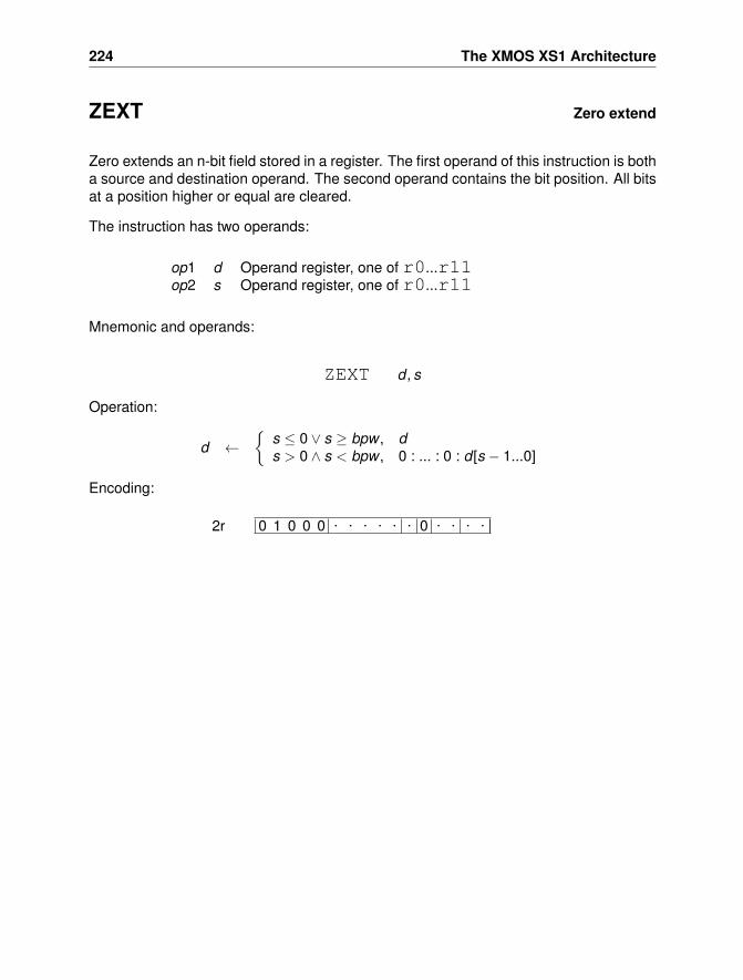
224 The XMOS XS1 Architecture
ZEXT Zero extend
Zero extends an n-bit field stored in a register. The first operand of this instruction is botha source and destination operand. The second operand contains the bit position. All bitsat a position higher or equal are cleared.
The instruction has two operands:
op1 d Operand register, one of r0...r11op2 s Operand register, one of r0...r11
Mnemonic and operands:
ZEXT d , s
Operation:
d ←{
s ≤ 0 ∨ s ≥ bpw , ds > 0 ∧ s < bpw , 0 : ... : 0 : d [s − 1...0]
Encoding:
0 1 0 0 0 . . . . . . 0 . . . .2r
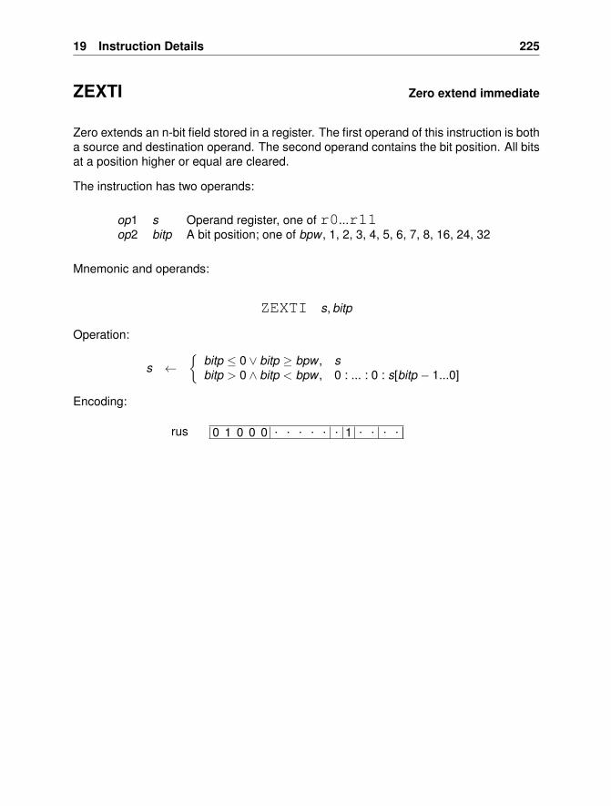
19 Instruction Details 225
ZEXTI Zero extend immediate
Zero extends an n-bit field stored in a register. The first operand of this instruction is botha source and destination operand. The second operand contains the bit position. All bitsat a position higher or equal are cleared.
The instruction has two operands:
op1 s Operand register, one of r0...r11op2 bitp A bit position; one of bpw , 1, 2, 3, 4, 5, 6, 7, 8, 16, 24, 32
Mnemonic and operands:
ZEXTI s, bitp
Operation:
s ←{
bitp ≤ 0 ∨ bitp ≥ bpw , sbitp > 0 ∧ bitp < bpw , 0 : ... : 0 : s[bitp − 1...0]
Encoding:
0 1 0 0 0 . . . . . . 1 . . . .rus
226 The XMOS XS1 Architecture
19.2 Instruction Format Specification
This chapter presents the instruction-formats. For each instruction format there is aname, a short description of its purpose, then a graphical representation of the encoding,and finally a list of instructions that use this instruction encoding.
The graphical representation comprises two or four bytes, presented as one or twogroups of 16 bits. For each of them, bits are numbered from 15 down to 0. If a bitvalue depends on the opcode, then this is marked with a “×” symbol. If a bit valuedepends on an operand this is marked with a “·”, and the particular encoding for thatoperand is shown underneath. Otherwise, the bit will have a value of 0 or 1, in order todifferentiate between formats.
All “long” formats comprise either a prefix instruction to specify an extra 10 bits of im-mediate operand and a prefixable instruction, or they comprise two instruction wordsallowing instructions with up to six operands to be represented.
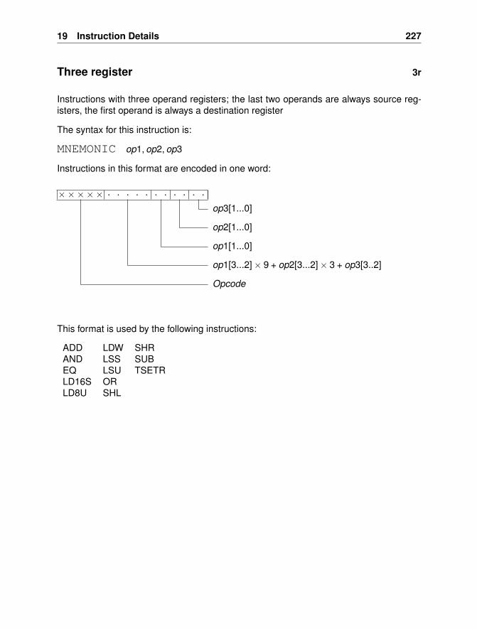
19 Instruction Details 227
Three register 3r
Instructions with three operand registers; the last two operands are always source reg-isters, the first operand is always a destination register
The syntax for this instruction is:
MNEMONIC op1, op2, op3
Instructions in this format are encoded in one word:
××××× . . . . . . . . . . .
op3[1...0]
op2[1...0]
op1[1...0]
op1[3...2]× 9 + op2[3...2]× 3 + op3[3..2]
Opcode
This format is used by the following instructions:
ADD LDW SHRAND LSS SUBEQ LSU TSETRLD16S ORLD8U SHL
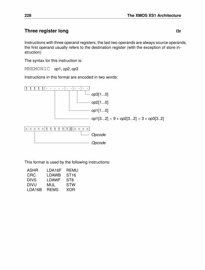
228 The XMOS XS1 Architecture
Three register long l3r
Instructions with three operand registers; the last two operands are always source operands,the first operand usually refers to the destination register (with the exception of store in-struction)
The syntax for this instruction is:
MNEMONIC op1, op2, op3
Instructions in this format are encoded in two words:
××××× 1 1 1 1 1 1 0 ××××Opcode
Opcode
1 1 1 1 1 . . . . . . . . . . .
op3[1...0]
op2[1...0]
op1[1...0]
op1[3...2]× 9 + op2[3...2]× 3 + op3[3..2]
This format is used by the following instructions:
ASHR LDA16F REMUCRC LDAWB ST16DIVS LDAWF ST8DIVU MUL STWLDA16B REMS XOR
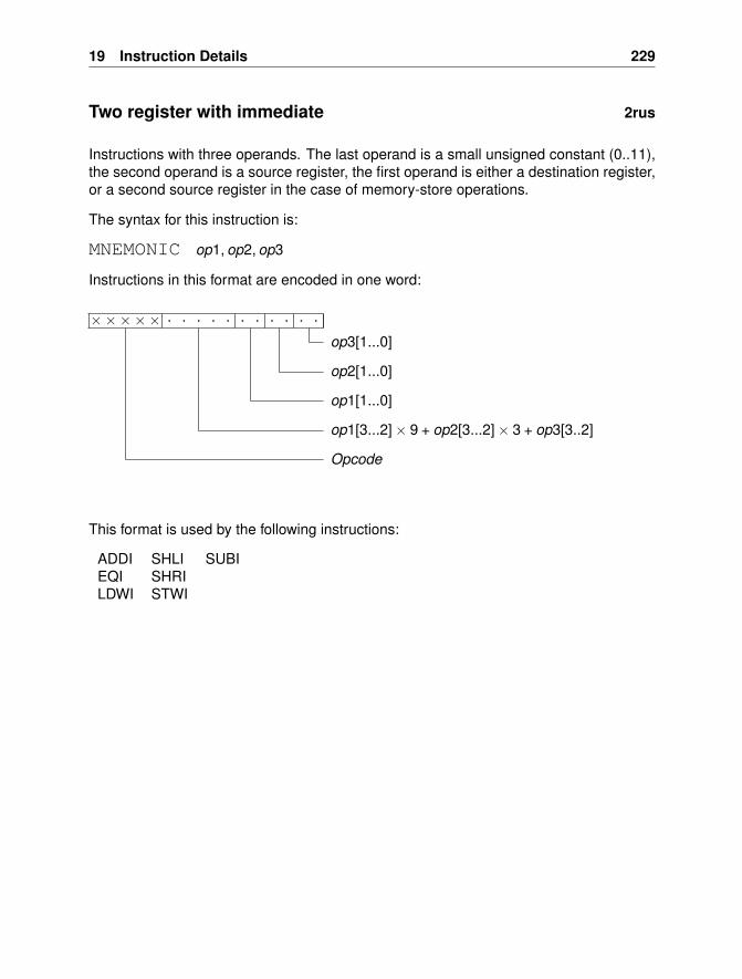
19 Instruction Details 229
Two register with immediate 2rus
Instructions with three operands. The last operand is a small unsigned constant (0..11),the second operand is a source register, the first operand is either a destination register,or a second source register in the case of memory-store operations.
The syntax for this instruction is:
MNEMONIC op1, op2, op3
Instructions in this format are encoded in one word:
××××× . . . . . . . . . . .
op3[1...0]
op2[1...0]
op1[1...0]
op1[3...2]× 9 + op2[3...2]× 3 + op3[3..2]
Opcode
This format is used by the following instructions:
ADDI SHLI SUBIEQI SHRILDWI STWI
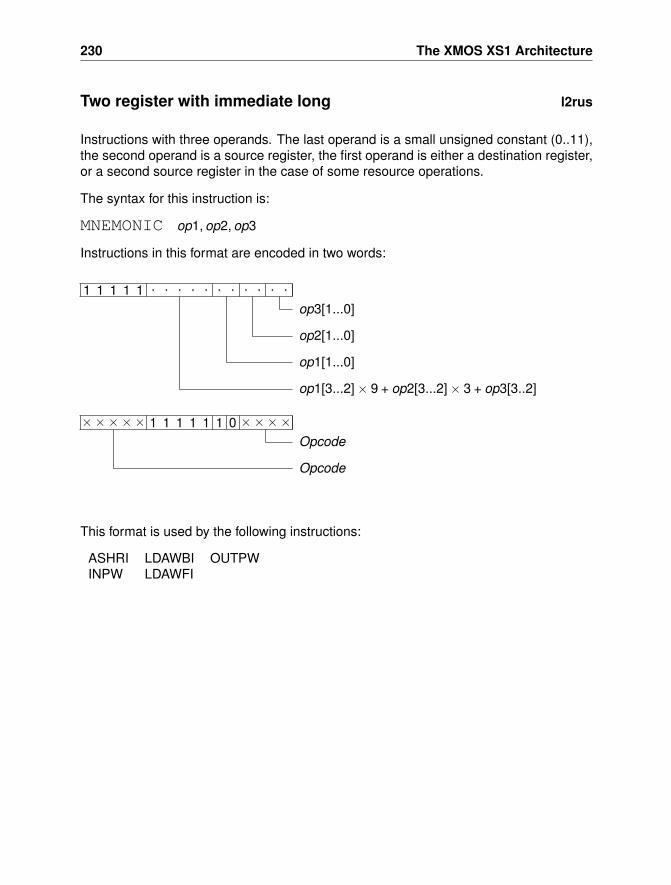
230 The XMOS XS1 Architecture
Two register with immediate long l2rus
Instructions with three operands. The last operand is a small unsigned constant (0..11),the second operand is a source register, the first operand is either a destination register,or a second source register in the case of some resource operations.
The syntax for this instruction is:
MNEMONIC op1, op2, op3
Instructions in this format are encoded in two words:
××××× 1 1 1 1 1 1 0 ××××Opcode
Opcode
1 1 1 1 1 . . . . . . . . . . .
op3[1...0]
op2[1...0]
op1[1...0]
op1[3...2]× 9 + op2[3...2]× 3 + op3[3..2]
This format is used by the following instructions:
ASHRI LDAWBI OUTPWINPW LDAWFI
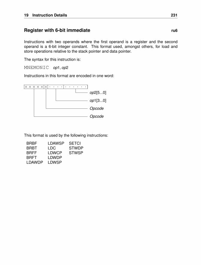
19 Instruction Details 231
Register with 6-bit immediate ru6
Instructions with two operands where the first operand is a register and the secondoperand is a 6-bit integer constant. This format used, amongst others, for load andstore operations relative to the stack pointer and data pointer.
The syntax for this instruction is:
MNEMONIC op1, op2
Instructions in this format are encoded in one word:
×××××× . . . . . . . . . .
op2[5...0]
op1[3...0]
Opcode
Opcode
This format is used by the following instructions:
BRBF LDAWSP SETCIBRBT LDC STWDPBRFF LDWCP STWSPBRFT LDWDPLDAWDP LDWSP
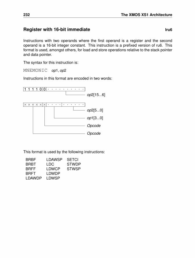
232 The XMOS XS1 Architecture
Register with 16-bit immediate lru6
Instructions with two operands where the first operand is a register and the secondoperand is a 16-bit integer constant. This instruction is a prefixed version of ru6. Thisformat is used, amongst others, for load and store operations relative to the stack pointerand data pointer.
The syntax for this instruction is:
MNEMONIC op1, op2
Instructions in this format are encoded in two words:
×××××× . . . . . . . . . .
op2[5...0]
op1[3...0]
Opcode
Opcode
1 1 1 1 0 0 . . . . . . . . . .
op2[15...6]
This format is used by the following instructions:
BRBF LDAWSP SETCIBRBT LDC STWDPBRFF LDWCP STWSPBRFT LDWDPLDAWDP LDWSP
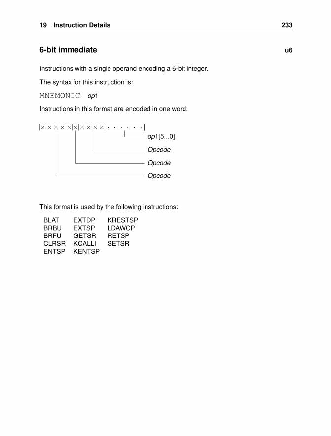
19 Instruction Details 233
6-bit immediate u6
Instructions with a single operand encoding a 6-bit integer.
The syntax for this instruction is:
MNEMONIC op1
Instructions in this format are encoded in one word:
×××××××××× . . . . . .
op1[5...0]
Opcode
Opcode
Opcode
This format is used by the following instructions:
BLAT EXTDP KRESTSPBRBU EXTSP LDAWCPBRFU GETSR RETSPCLRSR KCALLI SETSRENTSP KENTSP
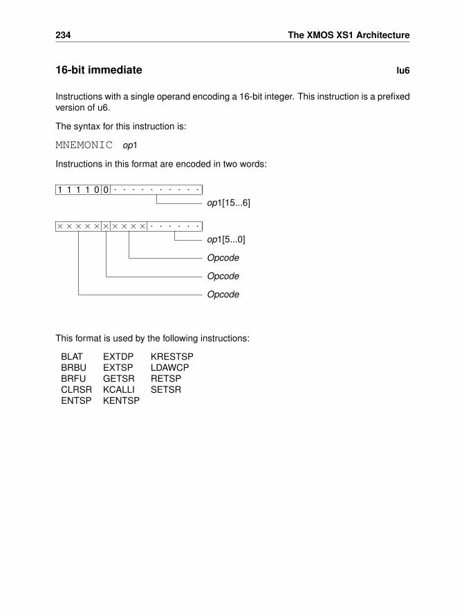
234 The XMOS XS1 Architecture
16-bit immediate lu6
Instructions with a single operand encoding a 16-bit integer. This instruction is a prefixedversion of u6.
The syntax for this instruction is:
MNEMONIC op1
Instructions in this format are encoded in two words:
×××××××××× . . . . . .
op1[5...0]
Opcode
Opcode
Opcode
1 1 1 1 0 0 . . . . . . . . . .
op1[15...6]
This format is used by the following instructions:
BLAT EXTDP KRESTSPBRBU EXTSP LDAWCPBRFU GETSR RETSPCLRSR KCALLI SETSRENTSP KENTSP
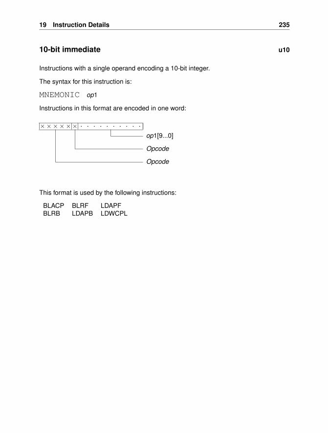
19 Instruction Details 235
10-bit immediate u10
Instructions with a single operand encoding a 10-bit integer.
The syntax for this instruction is:
MNEMONIC op1
Instructions in this format are encoded in one word:
×××××× . . . . . . . . . .
op1[9...0]
Opcode
Opcode
This format is used by the following instructions:
BLACP BLRF LDAPFBLRB LDAPB LDWCPL
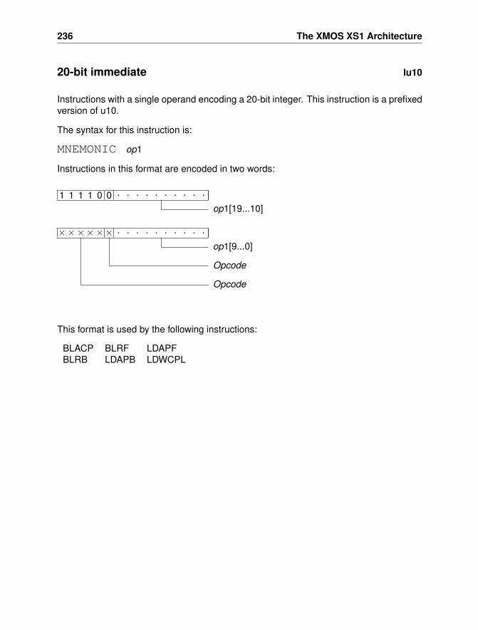
236 The XMOS XS1 Architecture
20-bit immediate lu10
Instructions with a single operand encoding a 20-bit integer. This instruction is a prefixedversion of u10.
The syntax for this instruction is:
MNEMONIC op1
Instructions in this format are encoded in two words:
×××××× . . . . . . . . . .
op1[9...0]
Opcode
Opcode
1 1 1 1 0 0 . . . . . . . . . .
op1[19...10]
This format is used by the following instructions:
BLACP BLRF LDAPFBLRB LDAPB LDWCPL
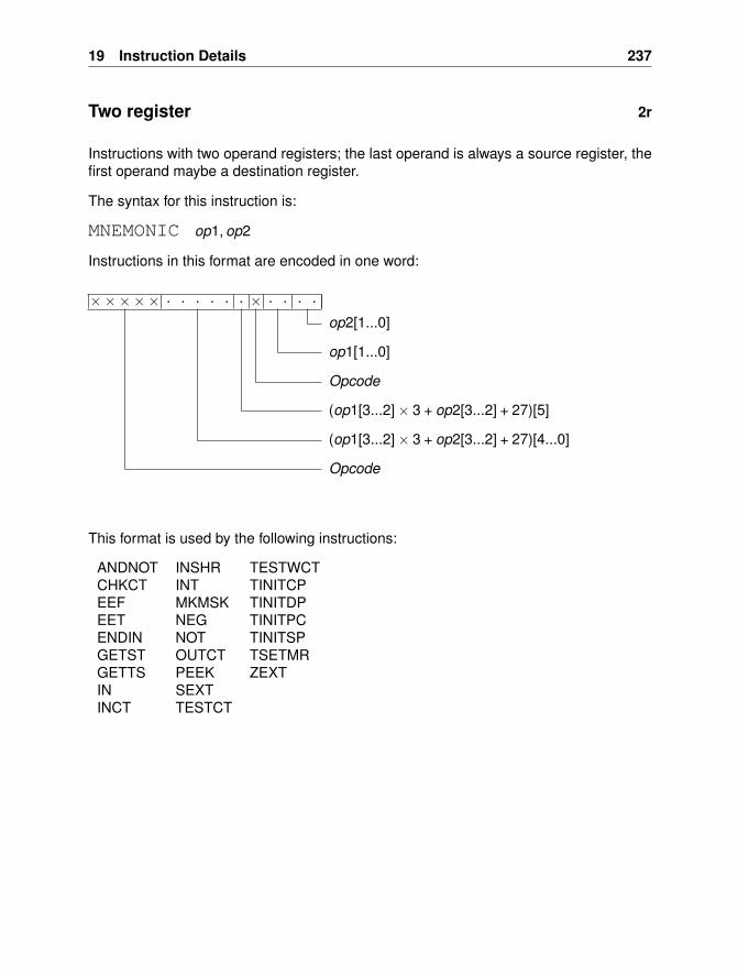
19 Instruction Details 237
Two register 2r
Instructions with two operand registers; the last operand is always a source register, thefirst operand maybe a destination register.
The syntax for this instruction is:
MNEMONIC op1, op2
Instructions in this format are encoded in one word:
××××× . . . . . . × . . . .
op2[1...0]
op1[1...0]
Opcode
(op1[3...2]× 3 + op2[3...2] + 27)[5]
(op1[3...2]× 3 + op2[3...2] + 27)[4...0]
Opcode
This format is used by the following instructions:
ANDNOT INSHR TESTWCTCHKCT INT TINITCPEEF MKMSK TINITDPEET NEG TINITPCENDIN NOT TINITSPGETST OUTCT TSETMRGETTS PEEK ZEXTIN SEXTINCT TESTCT
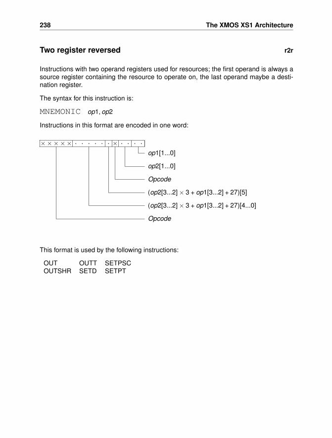
238 The XMOS XS1 Architecture
Two register reversed r2r
Instructions with two operand registers used for resources; the first operand is always asource register containing the resource to operate on, the last operand maybe a desti-nation register.
The syntax for this instruction is:
MNEMONIC op1, op2
Instructions in this format are encoded in one word:
××××× . . . . . . × . . . .
op1[1...0]
op2[1...0]
Opcode
(op2[3...2]× 3 + op1[3...2] + 27)[5]
(op2[3...2]× 3 + op1[3...2] + 27)[4...0]
Opcode
This format is used by the following instructions:
OUT OUTT SETPSCOUTSHR SETD SETPT
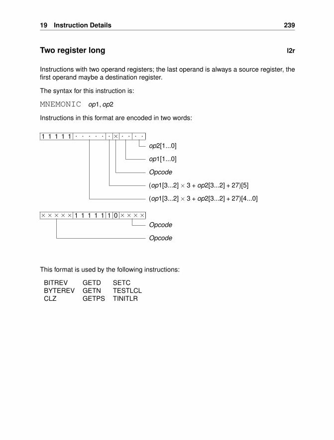
19 Instruction Details 239
Two register long l2r
Instructions with two operand registers; the last operand is always a source register, thefirst operand maybe a destination register.
The syntax for this instruction is:
MNEMONIC op1, op2
Instructions in this format are encoded in two words:
××××× 1 1 1 1 1 1 0 ××××Opcode
Opcode
1 1 1 1 1 . . . . . . × . . . .
op2[1...0]
op1[1...0]
Opcode
(op1[3...2]× 3 + op2[3...2] + 27)[5]
(op1[3...2]× 3 + op2[3...2] + 27)[4...0]
This format is used by the following instructions:
BITREV GETD SETCBYTEREV GETN TESTLCLCLZ GETPS TINITLR
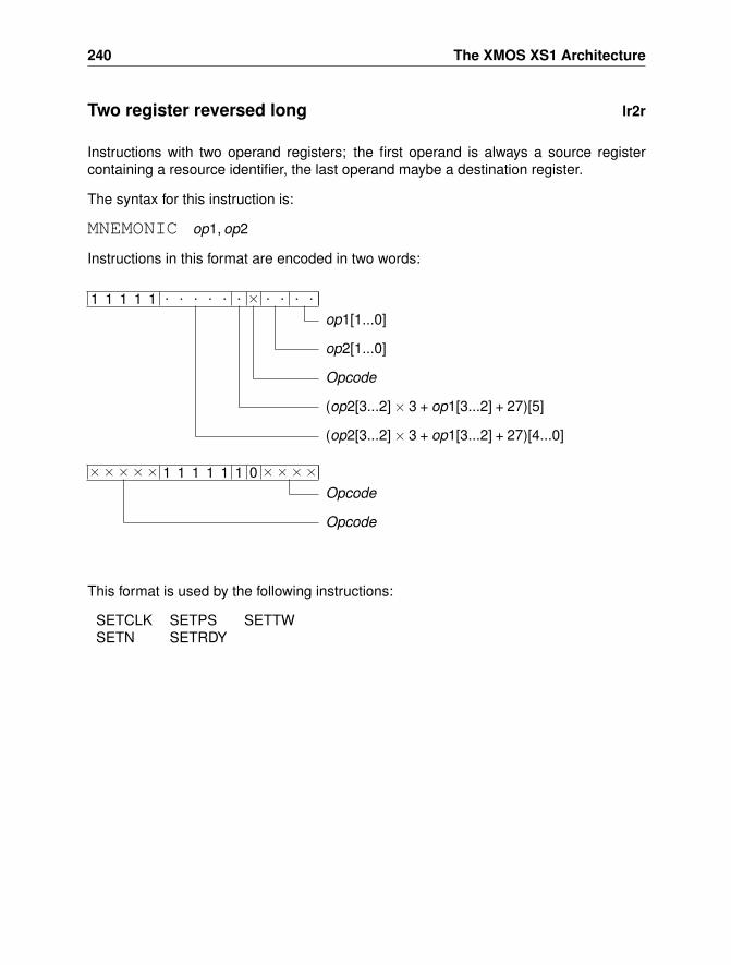
240 The XMOS XS1 Architecture
Two register reversed long lr2r
Instructions with two operand registers; the first operand is always a source registercontaining a resource identifier, the last operand maybe a destination register.
The syntax for this instruction is:
MNEMONIC op1, op2
Instructions in this format are encoded in two words:
××××× 1 1 1 1 1 1 0 ××××Opcode
Opcode
1 1 1 1 1 . . . . . . × . . . .
op1[1...0]
op2[1...0]
Opcode
(op2[3...2]× 3 + op1[3...2] + 27)[5]
(op2[3...2]× 3 + op1[3...2] + 27)[4...0]
This format is used by the following instructions:
SETCLK SETPS SETTWSETN SETRDY
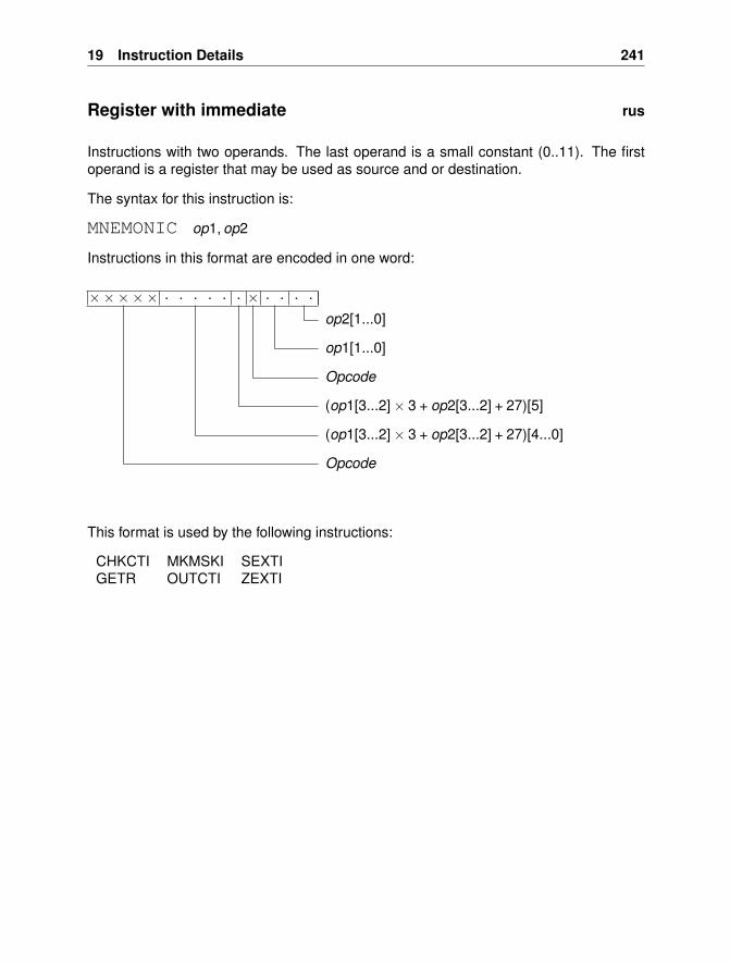
19 Instruction Details 241
Register with immediate rus
Instructions with two operands. The last operand is a small constant (0..11). The firstoperand is a register that may be used as source and or destination.
The syntax for this instruction is:
MNEMONIC op1, op2
Instructions in this format are encoded in one word:
××××× . . . . . . × . . . .
op2[1...0]
op1[1...0]
Opcode
(op1[3...2]× 3 + op2[3...2] + 27)[5]
(op1[3...2]× 3 + op2[3...2] + 27)[4...0]
Opcode
This format is used by the following instructions:
CHKCTI MKMSKI SEXTIGETR OUTCTI ZEXTI
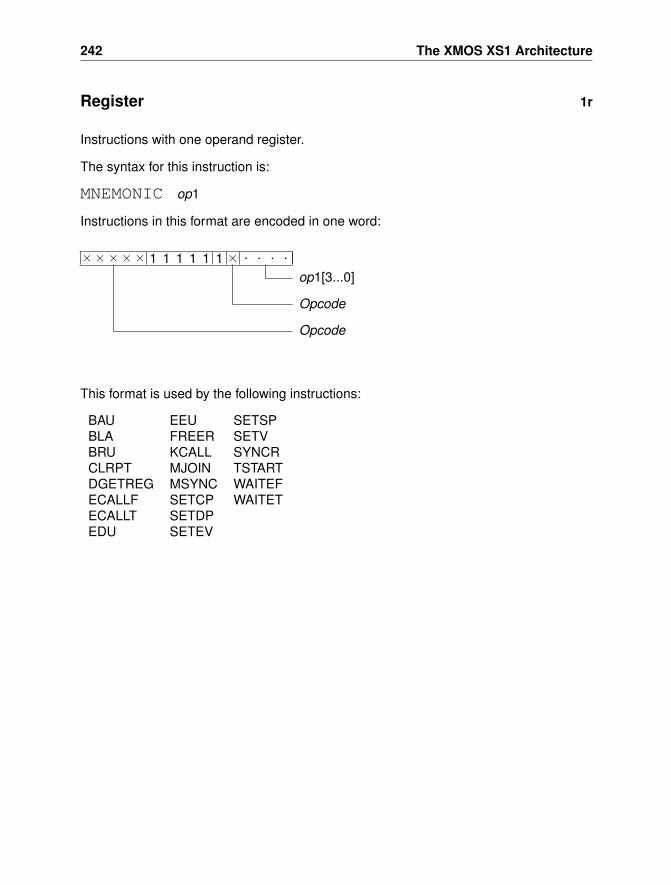
242 The XMOS XS1 Architecture
Register 1r
Instructions with one operand register.
The syntax for this instruction is:
MNEMONIC op1
Instructions in this format are encoded in one word:
××××× 1 1 1 1 1 1 × . . . .
op1[3...0]
Opcode
Opcode
This format is used by the following instructions:
BAU EEU SETSPBLA FREER SETVBRU KCALL SYNCRCLRPT MJOIN TSTARTDGETREG MSYNC WAITEFECALLF SETCP WAITETECALLT SETDPEDU SETEV
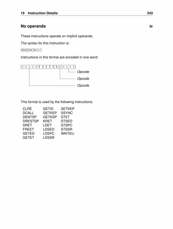
19 Instruction Details 243
No operands 0r
These instructions operate on implicit operands.
The syntax for this instruction is:
MNEMONIC
Instructions in this format are encoded in one word:
××××× 1 1 1 1 1 1 ×××××Opcode
Opcode
Opcode
This format is used by the following instructions:
CLRE GETID SETKEPDCALL GETKEP SSYNCDENTSP GETKSP STETDRESTSP KRET STSEDDRET LDET STSPCFREET LDSED STSSRGETED LDSPC WAITEUGETET LDSSR
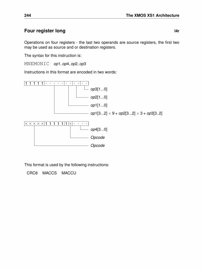
244 The XMOS XS1 Architecture
Four register long l4r
Operations on four registers - the last two operands are source registers, the first twomay be used as source and or destination registers.
The syntax for this instruction is:
MNEMONIC op1, op4, op2, op3
Instructions in this format are encoded in two words:
××××× 1 1 1 1 1 1 × . . . .
op4[3...0]
Opcode
Opcode
1 1 1 1 1 . . . . . . . . . . .
op3[1...0]
op2[1...0]
op1[1...0]
op1[3...2]× 9 + op2[3...2]× 3 + op3[3..2]
This format is used by the following instructions:
CRC8 MACCS MACCU
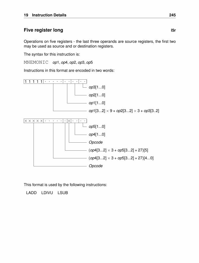
19 Instruction Details 245
Five register long l5r
Operations on five registers - the last three operands are source registers, the first twomay be used as source and or destination registers.
The syntax for this instruction is:
MNEMONIC op1, op4, op2, op3, op5
Instructions in this format are encoded in two words:
××××× . . . . . . × . . . .
op5[1...0]
op4[1...0]
Opcode
(op4[3...2]× 3 + op5[3...2] + 27)[5]
(op4[3...2]× 3 + op5[3...2] + 27)[4...0]
Opcode
1 1 1 1 1 . . . . . . . . . . .
op3[1...0]
op2[1...0]
op1[1...0]
op1[3...2]× 9 + op2[3...2]× 3 + op3[3..2]
This format is used by the following instructions:
LADD LDIVU LSUB
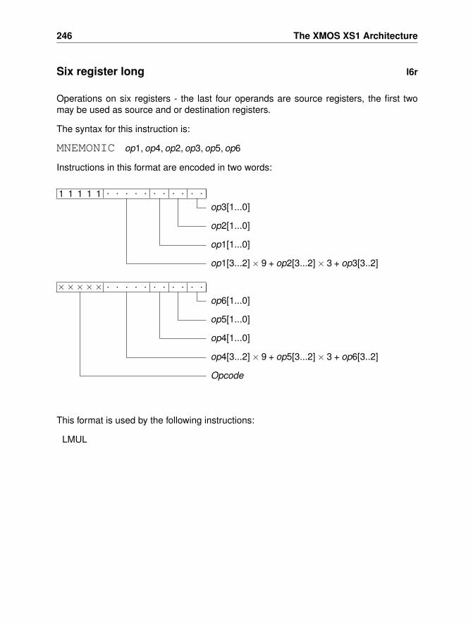
246 The XMOS XS1 Architecture
Six register long l6r
Operations on six registers - the last four operands are source registers, the first twomay be used as source and or destination registers.
The syntax for this instruction is:
MNEMONIC op1, op4, op2, op3, op5, op6
Instructions in this format are encoded in two words:
××××× . . . . . . . . . . .
op6[1...0]
op5[1...0]
op4[1...0]
op4[3...2]× 9 + op5[3...2]× 3 + op6[3..2]
Opcode
1 1 1 1 1 . . . . . . . . . . .
op3[1...0]
op2[1...0]
op1[1...0]
op1[3...2]× 9 + op2[3...2]× 3 + op3[3..2]
This format is used by the following instructions:
LMUL
19 Instruction Details 247
19.3 Exceptions
Exceptions change the normal flow of control on an XS1; they may be caused by inter-rupts, errors arising during instruction execution and by system calls. On an exception,the processor will save the pc and sr in spc and ssr , disable events and interrupts, andstart executing an exception handler. The program counter that is saved normally pointsto the instruction that raised the exception. Two registers are also set. The exception-data (ed) and exception-type (et) will be set to reflect the cause of the exception. Theexception handler can choose how to deal with the exception.
The different types of exception are listed in this section, together with their representa-tion, their meaning, and the instructions that may cause them.
248 The XMOS XS1 Architecture
ET LINK ERROR 1
A reserved hardware control token was output to a channel end. Alternatively, a channelend was used to transmit data without its destination being set first.
When ET LINK ERROR is raised:
• et will be set to 1.
• ed will be set to the resource ID of the channel end which generated the exception.
This exception may be raised by the following instructions:
OUT OUTCT OUTT
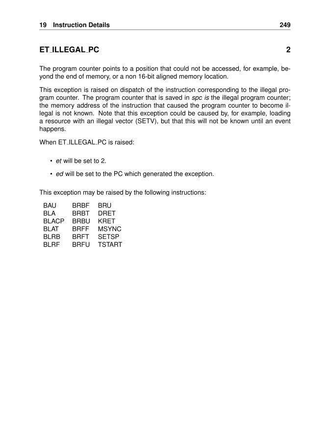
19 Instruction Details 249
ET ILLEGAL PC 2
The program counter points to a position that could not be accessed, for example, be-yond the end of memory, or a non 16-bit aligned memory location.
This exception is raised on dispatch of the instruction corresponding to the illegal pro-gram counter. The program counter that is saved in spc is the illegal program counter;the memory address of the instruction that caused the program counter to become il-legal is not known. Note that this exception could be caused by, for example, loadinga resource with an illegal vector (SETV), but that this will not be known until an eventhappens.
When ET ILLEGAL PC is raised:
• et will be set to 2.
• ed will be set to the PC which generated the exception.
This exception may be raised by the following instructions:
BAU BRBF BRUBLA BRBT DRETBLACP BRBU KRETBLAT BRFF MSYNCBLRB BRFT SETSPBLRF BRFU TSTART
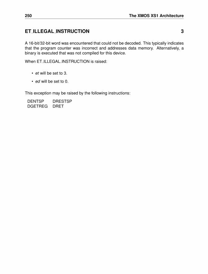
250 The XMOS XS1 Architecture
ET ILLEGAL INSTRUCTION 3
A 16-bit/32-bit word was encountered that could not be decoded. This typically indicatesthat the program counter was incorrect and addresses data memory. Alternatively, abinary is executed that was not compiled for this device.
When ET ILLEGAL INSTRUCTION is raised:
• et will be set to 3.
• ed will be set to 0.
This exception may be raised by the following instructions:
DENTSP DRESTSPDGETREG DRET
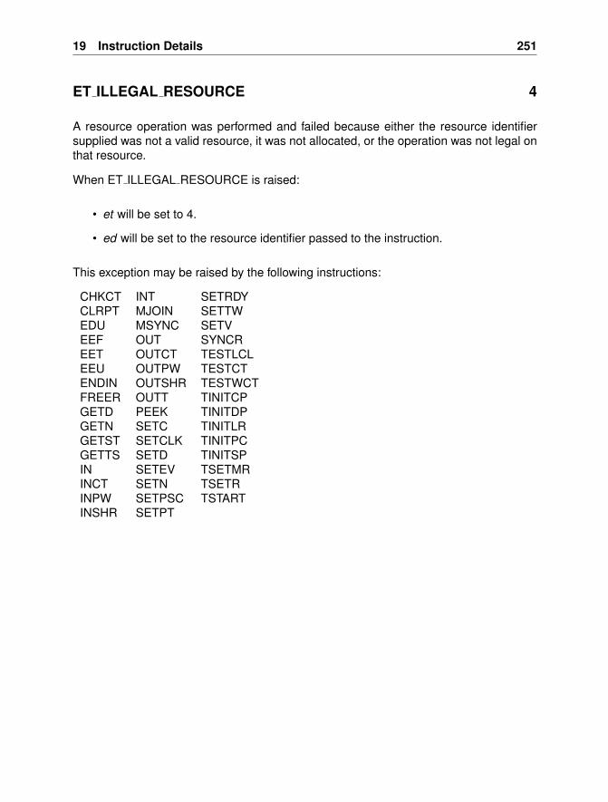
19 Instruction Details 251
ET ILLEGAL RESOURCE 4
A resource operation was performed and failed because either the resource identifiersupplied was not a valid resource, it was not allocated, or the operation was not legal onthat resource.
When ET ILLEGAL RESOURCE is raised:
• et will be set to 4.
• ed will be set to the resource identifier passed to the instruction.
This exception may be raised by the following instructions:
CHKCT INT SETRDYCLRPT MJOIN SETTWEDU MSYNC SETVEEF OUT SYNCREET OUTCT TESTLCLEEU OUTPW TESTCTENDIN OUTSHR TESTWCTFREER OUTT TINITCPGETD PEEK TINITDPGETN SETC TINITLRGETST SETCLK TINITPCGETTS SETD TINITSPIN SETEV TSETMRINCT SETN TSETRINPW SETPSC TSTARTINSHR SETPT
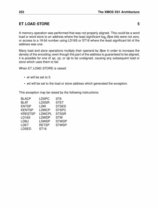
252 The XMOS XS1 Architecture
ET LOAD STORE 5
A memory operation was performed that was not properly aligned. This could be a wordload or word store to an address where the least significant log2 Bpw bits were not zero,or access to a 16-bit number using LD16S or ST16 where the least significant bit of theaddress was one.
Many load and store operations multiply their operand by Bpw in order to increase thedensity of the encoding; even though this part of the address is guaranteed to be aligned,it is possible for one of sp, cp, or dp to be unaligned, causing any subsequent load orstore which uses them to fail.
When ET LOAD STORE is raised:
• et will be set to 5.
• ed will be set to the load or store address which generated the exception.
This exception may be raised by the following instructions:
BLACP LDSPC ST8BLAT LDSSR STETENTSP LDW STSEDKENTSP LDWCP STSPCKRESTSP LDWCPL STSSRLD16S LDWDP STWLD8U LDWSP STWDPLDET RETSP STWSPLDSED ST16
19 Instruction Details 253
ET ILLEGAL PS 6
Access to a non existent processor status register was requested by either GETPS orSETPS.
When ET ILLEGAL PS is raised:
• et will be set to 6.
• ed will be set to the processor status register identifier.
This exception may be raised by the following instructions:
GETPS SETPS
254 The XMOS XS1 Architecture
ET ARITHMETIC 7
Signals an arithmetic error, for example a division by 0 or an overflow that was detected.
When ET ARITHMETIC is raised:
• et will be set to 7.
• ed will be set to 0.
This exception may be raised by the following instructions:
DIVS LDIVU REMUDIVU REMS
19 Instruction Details 255
ET ECALL 8
An ECALL instruction was executed, and the associated condition caused an exception.Indicates that the application program raised an exception, for example to signal arraybound errors or a failed assertion.
When ET ECALL is raised:
• et will be set to 8.
• ed will be set to 0.
This exception may be raised by the following instructions:
ECALLF ECALLT
256 The XMOS XS1 Architecture
ET RESOURCE DEP 9
Resources are owned and used by a single thread. If multiple threads attempt to accessthe same resource within 4 cycles of each other, a Resource Dependency exception willbe raised.
When ET RESOURCE DEP is raised:
• et will be set to 9.
• ed will be set to the resource identifier supplied by the instruction.
This exception may be raised by the following instructions:
CHKCT INT SETRDYCLRPT MJOIN SETTWEDU MSYNC SETVEEF OUT SYNCREET OUTCT TESTLCLEEU OUTPW TESTCTENDIN OUTSHR TESTWCTFREER OUTT TINITCPGETD PEEK TINITDPGETN SETC TINITLRGETST SETCLK TINITPCGETTS SETD TINITSPIN SETEV TSETMRINCT SETN TSETRINPW SETPSC TSTARTINSHR SETPT
19 Instruction Details 257
ET KCALL 15
Indicates that the KCALL or KCALLI instruction was executed.
When ET KCALL is raised:
• et will be set to 15.
• ed will be set to the kernel call operand.
This exception may be raised by the following instructions:
KCALL
IndexBranching, Jumping and Calling
Adjust stack and save link register, 90Branch absolute unconditional register,
53Branch and link absolute via constant
pool, 56Branch and link absolute via register,
55Branch and link absolute via table, 57Branch and link relative backwards, 58Branch and link relative forwards, 59Branch relative backwards false, 60Branch relative backwards true, 61Branch relative backwards unconditional,
62Branch relative forward false, 63Branch relative forward true, 64Branch relative forward unconditional,
65Branch relative unconditional register,
66Extend data, 93Extend stack, 94Return, 169Set constant pool, 175Set the data pointer, 177Set the stack pointer, 185
CommunicationGet network, 103Input a token of data, 114Input control tokens, 111Input data, 110Output a control token, 161Output a control token immediate, 162Output a token, 165Output data, 160Set network, 180
Test for control token, 68, 210Test for control token immediate, 69Test local, 209
Concurrency and Thread SynchronisationFree unsynchronised thread, 96Get a synchronised thread, 108Get the thread’s ID, 100Initialise a thread’s CP, 212Initialise a thread’s DP, 213Initialise a thread’s LR, 214Initialise a thread’s PC, 215Initialise a thread’s SP, 216Master synchronise, 155Set register in thread, 218Set the master’s register, 217Slave synchronise, 195Start thread, 219Synchronise and join, 152
Data Access16-bit store, 1968-bit store, 197Add to a 16-bit address, 124Add to a word address, 131Add to a word address immediate, 132Load address of word in constant pool,
129Load address of word in data pool, 130Load address of word on stack, 133Load backward pc-relative address, 125Load constant, 134Load ET from the stack, 135Load forward pc-relative address, 126Load SED from stack, 137Load signed 16 bits, 121Load SSR from stack, 139Load the SPC from the stack, 138Load unsigned 8 bits, 122
Index 259
Load word, 140Load word form data pool, 144Load word from constant pool, 142Load word from large constant pool,
143Load word from stack, 145Load word immediate, 141Make n-bit mask, 153Make n-bit mask immediate, 154Set constant pool, 175Set the data pointer, 177Set the stack pointer, 185Sign extend an n-bit field, 189Sign extend an n-bit field immediate,
190Store ET on the stack, 198Store SED on the stack, 199Store SPC on the stack, 200Store the SSR to the stack, 201Store word, 202Store word immediate, 203Store word in data pool, 204Store word on stack, 205Subtract from 16-bit address, 123Subtract from word address, 127Subtract from word address immedi-
ate, 128Zero extend, 224Zero extend immediate, 225
Data Manipulation8-step CRC, 75And not, 50Arithmetic shift right, 51Arithmetic shift right immediate, 52Bit reverse, 54Bitwise and, 49Bitwise exclusive or, 223Bitwise not, 158Bitwise or, 159Byte reverse, 67Count leading zeros, 73
Equal, 91Equal immediate, 92Integer unsigned add, 47Integer unsigned add immediate, 48Integer unsigned subtraction, 206Integer unsigned subtraction immedi-
ate, 207Less than signed, 147Less than unsigned, 148Long multiply, 146Long unsigned add with carry, 120Long unsigned divide, 136Long unsigned subtract, 149Make n-bit mask, 153Make n-bit mask immediate, 154Multiply and accumulate signed, 150Multiply and accumulate unsigned, 151Shift left, 191Shift left immediate, 192Shift right, 193Shift right immediate, 194Sign extend an n-bit field, 189Sign extend an n-bit field immediate,
190Signed division, 79Signed remainder, 167Two’s complement negate, 157Unsigned divide, 80Unsigned multiply, 156Unsigned remainder, 168word CRC, 74Zero extend, 224Zero extend immediate, 225
DebuggingCall a debug interrupt, 76Debug read of another thread’s regis-
ter, 78Get processor state, 104Restore non debug stack pointer, 81Return from debug interrupt, 82
260 The XMOS XS1 Architecture
Save and modify stack pointer for de-bug, 77
Set processor state, 181
Event HandlingClear all events, 70Clear bits SR, 72Enable events conditionally, 87Enables events conditionally, 86Get bits from SR, 107If false wait for event, 220If true wait for event, 221Set bits in SR, 186Unconditionally disable event, 85Unconditionally enable event, 88Wait for event, 222
ExceptionsET ARITHMETIC, 254ET ECALL, 255ET ILLEGAL INSTRUCTION, 250ET ILLEGAL PC, 249ET ILLEGAL PS, 253ET ILLEGAL RESOURCE, 251ET KCALL, 257ET LINK ERROR, 248ET LOAD STORE, 252ET RESOURCE DEP, 256
Formats10-bit immediate, 23516-bit immediate, 23420-bit immediate, 2366-bit immediate, 233Five register long, 245Four register long, 244No operands, 243Register, 242Register with 16-bit immediate, 232Register with 6-bit immediate, 231Register with immediate, 241Six register long, 246
Three register, 227Three register long, 228Two register, 237Two register long, 239Two register reversed, 238Two register reversed long, 240Two register with immediate, 229Two register with immediate long, 230
Interrupts, Exceptions and Kernel CallsClear bits SR, 72Get bits from SR, 107Get ED into r11, 98Get ET into r11, 99Get Kernel Stack Pointer, 102Get the Kernel Entry Point, 101Kernel call, 115Kernel call immediate, 116Kernel Return, 119Restore stack pointer from kernel stack,
118Set bits in SR, 186Set the kernel entry point, 179Switch to kernel stack, 117Throw exception if non-zero, 84Throw exception if zero, 83
Resource OperationsClear the port time, 71End a current input, 89Free a resource, 95Get a resource, 105Get resource data, 97Get the time stamp, 109Input a part word, 112Input and shift right, 113Input data, 110Output a part word, 163Output data, 160Output data and shift, 164Peek at port data, 166
Index 261
Set clock for a resource, 174Set environment vector, 178Set event data, 176Set event vector, 188Set ready input for a port, 184Set resource control bits, 172Set resource control bits immediate, 170Set the port shift count, 182Set the port time, 183Set transfer width for a port, 187Synchronise a resource, 208Test for position of control token, 211


![Energy Consumption Analysis of Programs based on XMOS ISA ...cliplab.org/papers/isa-energy-lopstr13-final.pdf · ISA (Instruction Set Architecture) code compiled from XC [24]. XC](https://static.documents.pub/doc/80x56/5f1d6b451c4b8345673d672f/energy-consumption-analysis-of-programs-based-on-xmos-isa-isa-instruction-set.jpg)
