CAEVimedix™ User Guide 905K802252 v. 1.2 October 2020 PROPRIETARY NOTICE: This document, including the information contained herein, is confidential and/or proprietary to CAE Inc., and shall not be reproduced or disclosed in whole or in part, or used for any purpose whatsoever without the prior written authorization of CAE Inc.
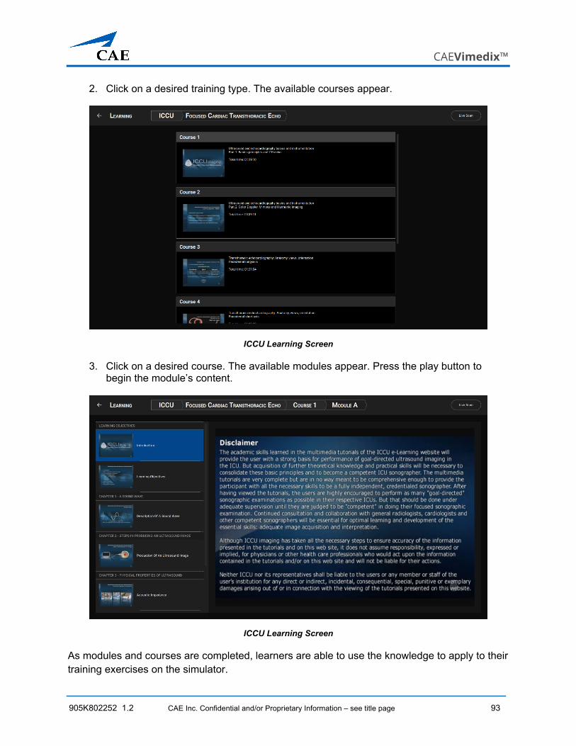
Transcript
CAEVimedix™ User Guide
905K802252 v. 1.2 October 2020
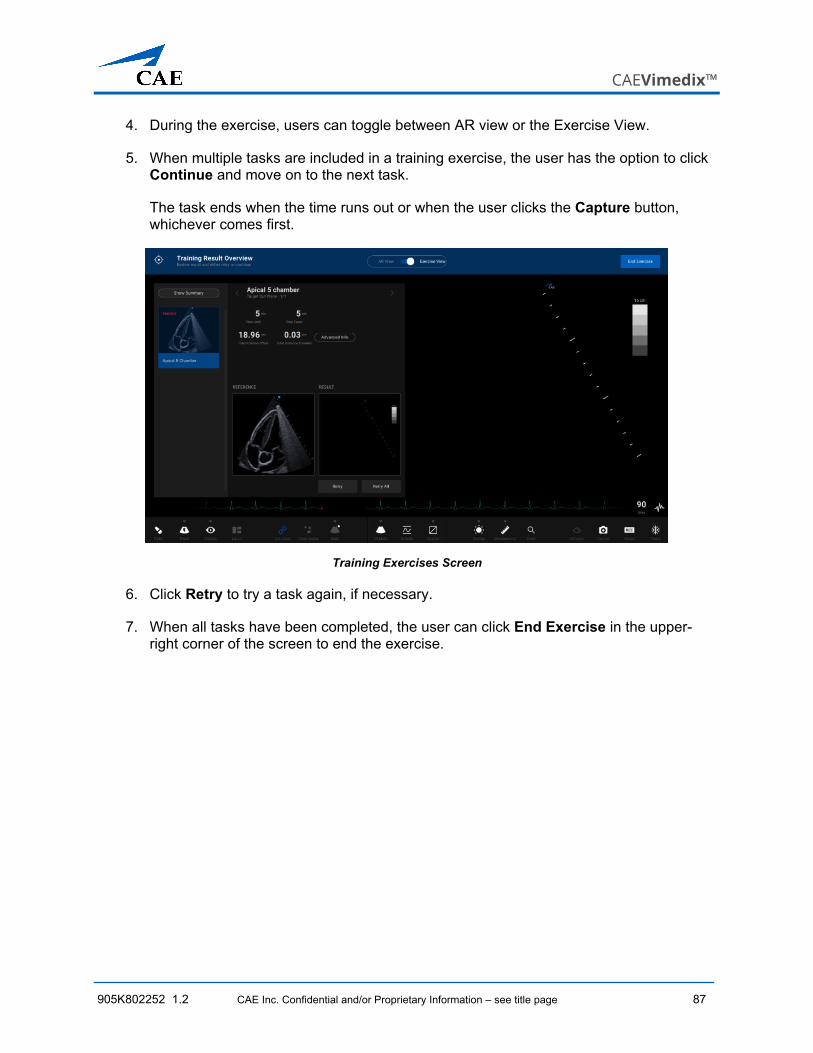
PROPRIETARY NOTICE: This document, including the information contained herein, is confidential and/or proprietary to CAE Inc., and shall not be reproduced or disclosed in whole or in part, or used for any purpose whatsoever without the prior written authorization of CAE Inc.
905K802252 v 1.2 CAE Inc. Confidential and/or Proprietary Information – see title page v
CAUTIONS AND WARNINGS Please read and understand these cautions and warnings before you begin using the Vimedix system.
• Do not use equipment in a manner that is not specified by the manufacturer. If equipment is used in a manner not specified by the manufacturer, the protection provided by the equipment may be impaired.
• Do not attempt to open or repair the Vimedix Ultrasonography Simulator or any of its components. Doing so can cause damage to the equipment and may void the warranty.
• Do not drop or hit probes against hard surfaces. The probes do not contain crystals but should be handled with care.
• Do not use ultrasound gel on Vimedix probes. Using gel may damage the equipment.
• Keep the simulator at least 40 inches (1 meter) away from large metal objects or surfaces to prevent image distortion or impact simulator performance. Objects that may cause interferences include:
o Metal table components
o Electric motors
o Strong speakers
o High amplification appliances
o Electric wires
o Large metal components such as metal filing cabinets
o Halogen lights
• When replacing damaged power cords, use only suitable power cord replacements.
• Keep the laptop/computer approximately 2 feet (60 cm) away from manikin to prevent image distortion.
• Ensure that no objects are left in the protective bag or on the manikin, as this could damage the surface of the manikin.
• Avoid any hydrocarbon solvents, as they react with and dissolve the surface of the manikin.
Cautions and Warnings
vi CAE Inc. Confidential and/or Proprietary Information – see title page 905K802252 1.02
• Do not immerse the manikin in liquid or use abundant liquid to wash the manikin. This could impair its normal function.
• Do not insert any USB devices other than a USB storage device (memory stick, flash drive). Other USB devices such as phone or mp3 chargers may create a simulator error.
• All equipment inquiries should be directed to the product manufacturer.
• Do not connect the probe to the SENSOR 2 port. The probe must be connected to the SENSOR 1 port.
ELECTRICAL SAFETY • This product must be connected to an electrical outlet that is properly grounded.
Precautions should be taken so that grounding or polarization is not defeated.
• Always use the supplied power cords. Do NOT substitute.
• Operate the system from a power source with the following rating:
o 110VAC, 50/60 hertz (cycles per second) (e.g., North America, Japan)
o 240VAC, 50/60 hertz (cycles per second) (e.g., Europe)
• Do NOT allow excess fluids to flow on or into electronic parts
• Do NOT attempt to disassemble the simulator or service any of the electrical components.
• Always use the supplied power adapter to charge or run simulator from AC.
MANIKINS • Do NOT disassemble factory-assembled parts of the manikin.
• Do NOT clean the manikin with chemical solvents or abrasive pads. Use only water and a light soap solution.
• Make sure that manikin is set up on a stable, sturdy work surface to avoid collapsing and causing injury to users.
• The manikin should be operated in ambient temperatures, between 41°F – 95°F (5°C – 35°C). Operating in temperatures outside this range may result in anomalous behavior and out of specification performance.
• Do NOT introduce foreign substances into the orifices.
CAEVimedix™
905K802252 v 1.2 CAE Inc. Confidential and/or Proprietary Information – see title page vii
Table of Contents Versioning ..................................................................................................................................... iii Specifications ............................................................................................................................... iv
Cautions and Warnings ................................................................................................................. v
Electrical Safety ........................................................................................................................ vi Manikins ................................................................................................................................... vi
xii CAE Inc. Confidential and/or Proprietary Information – see title page 905K802252 1.02
CAEVimedix™
905K802252 v 1.2 CAE Inc. Confidential and/or Proprietary Information – see title page 1
INTRODUCTION This CAE VimedixTM Ultrasonography Abridged User Guide provides information about the Vimedix hardware and the new user interface of Vimedix 3.1.
Using real-time dynamic imaging and a custom designed manikin, the Vimedix ultrasonography simulator provides healthcare professionals with an unparalleled training environment for scanning the thoracic, abdominal and pelvic cavities for basic to complex cases. Learners can perform a realistic ultrasonography assessment of cardiac, abdominal and pelvic structures, practice hand-eye coordination and probe handling and improve pathology and case recognition skills. Instructors also have the ability to enhance distance learning experiences with the use of screen sharing software and remote user access so learners can virtually manipulate and operate the simulator from wherever they are.
IMPORTANT: The Vimedix ultrasonography simulator is a training tool. The simulator is not intended to diagnose the condition of a live human being or identify a life-threatening situation. The Vimedix ultrasonography simulator is one of a series of didactic tools that can be used to improve ultrasonography training. This simulator is not intended to replace any courses or hands-on sessions with live subjects but should be implemented as part of a blended learning solution.
IN THIS GUIDE This User Guide has been designed for quick access to information on how to use and maintain the Vimedix simulator. Please be sure to read and follow the Cautions and Warnings on the pages preceding the Table of Contents. This is for the safety of users as well as for the protection of the simulator.
The Equipment Overview outlines the items that come standard with the purchase of a Vimedix unit and items that pertain only to specific modules.
The Setup section and Starting the Simulator section provide instructions that should be consulted prior to using the Vimedix simulator.
The Using the Simulator section provides information about using the features and functions found in the software for the Bob 1.3 and Catherine manikins and the available modules.
The Care and Maintenance section contains warranty details and cleanup and care instructions that must be followed to ensure optimal functioning of the Vimedix simulator.
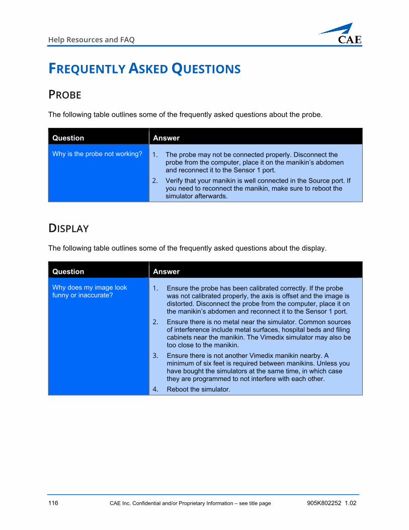
The Frequently Asked Questions section addresses any common troubleshooting concerns.
The Keyboard Shortcuts and Mouse Controls section outlines the different keyboard shortcuts for the Vimedix software and how to manipulate the mouse controls.
Equipment Overview
2 CAE Inc. Confidential and/or Proprietary Information – see title page 905K802252 1.02
EQUIPMENT OVERVIEW You can choose from different basic platforms for the Vimedix Ultrasonography Simulator:
• Vimedix Cardiac
o Transthoracic Echocardiography (TTE)
o Transesophageal Echocardiography (TEE)
• Vimedix Abdo
o Regular Abdominal
o FAST Abdominal
• Vimedix Ob/Gyn
Once a basic platform is purchased, additional modules can be purchased as a system upgrade.
CAEVimedix™
905K802252 1.2 CAE Inc. Confidential and/or Proprietary Information – see title page 3
STANDARD EQUIPMENT Vimedix comes standard with the necessary equipment and inventory to use the ultrasonography simulator. Depending on the simulator package purchased, the equipment will include either the male manikin or the female manikin. The Vimedix laptop comes standard with Vimedix 3.1.
Note: Vimedix 2.0 PCs can be upgraded to the new Vimedix 3.1 user interface.
Standard Equipment
Male Manikin (Bob 1.3 and support stands (x2); with purchase of Cardiac or Abdo platform)
Female Manikin (Catherine; with purchase of Ob/Gyn platform)
Probe (refer to the Optional Equipment List for details)
Laptop
Power converter and power cord
Wireless mouse
External Motion Tracker and USB cable
Note: Check the inventory against your packing invoice to verify that all components have been received.
Equipment Overview
4 CAE Inc. Confidential and/or Proprietary Information – see title page 905K802252 1.02
THE MANIKINS Together with the chosen ultrasonography platform, CAE provides either a male or female life-size torso manikin, each equipped with a cable that connects to the external motion tracker to register probe activity and communicate with the Vimedix simulator laptop. The manikins have realistic tactile features including a depressible abdomen, palpable ribs and sternum, and depressible intercostal spaces.
Male Manikin: Bob 1.3
The latest generation male manikin model is Bob, version 1.3, featuring a one-piece head and torso. It also includes support stands allowing the manikin to be placed in a 45-degree tilted position.
The Male Manikin: Bob 1.3
Female Manikin: Catherine
For the Vimedix Ob/Gyn ultrasound simulator, CAE Healthcare provides a full-size female torso. The female manikin features include some depressibility in the abdomen for performing pelvic ultrasounds.
The Female Manikin: Catherine
CAEVimedix™
905K802252 1.2 CAE Inc. Confidential and/or Proprietary Information – see title page 5
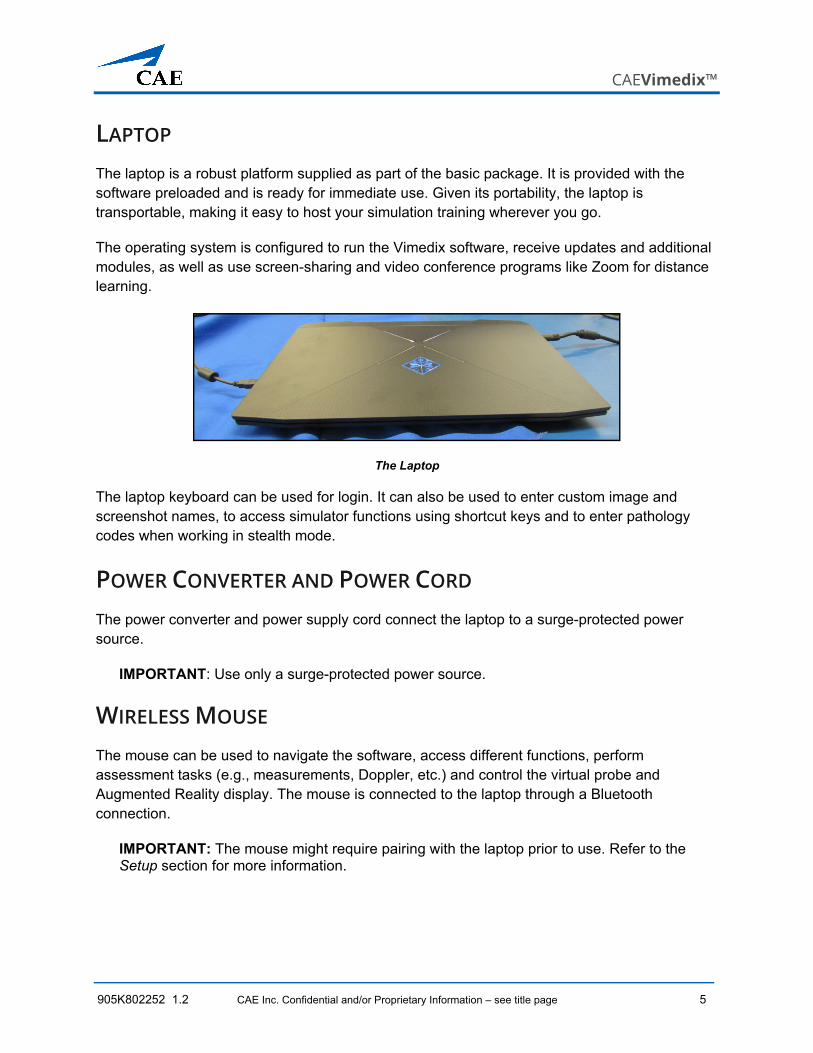
LAPTOP The laptop is a robust platform supplied as part of the basic package. It is provided with the software preloaded and is ready for immediate use. Given its portability, the laptop is transportable, making it easy to host your simulation training wherever you go.
The operating system is configured to run the Vimedix software, receive updates and additional modules, as well as use screen-sharing and video conference programs like Zoom for distance learning.
The Laptop
The laptop keyboard can be used for login. It can also be used to enter custom image and screenshot names, to access simulator functions using shortcut keys and to enter pathology codes when working in stealth mode.
POWER CONVERTER AND POWER CORD The power converter and power supply cord connect the laptop to a surge-protected power source.
IMPORTANT: Use only a surge-protected power source.
WIRELESS MOUSE The mouse can be used to navigate the software, access different functions, perform assessment tasks (e.g., measurements, Doppler, etc.) and control the virtual probe and Augmented Reality display. The mouse is connected to the laptop through a Bluetooth connection.
IMPORTANT: The mouse might require pairing with the laptop prior to use. Refer to the Setup section for more information.
Equipment Overview
6 CAE Inc. Confidential and/or Proprietary Information – see title page 905K802252 1.02
EXTERNAL MOTION TRACKER The external motion tracker receives input from the active manikin and probe and relays the information in real-time to the Vimedix simulator for a seamless display response.
A USB cable is provided to connect the external motion tracker to the laptop.
External Motion Tracker
OPTIONAL EQUIPMENT The Vimedix modules are purchased as packages which include all required equipment to effectively complete the training and pathologies.
905K802252 1.2 CAE Inc. Confidential and/or Proprietary Information – see title page 7
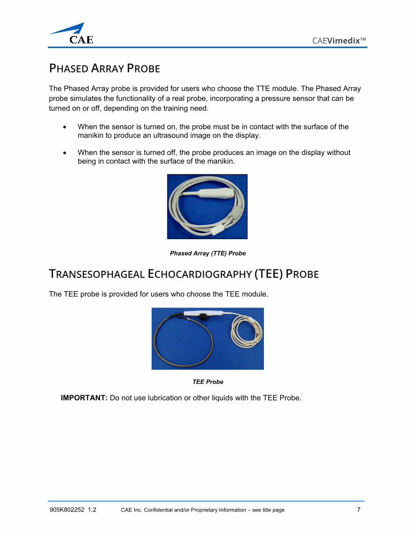
PHASED ARRAY PROBE The Phased Array probe is provided for users who choose the TTE module. The Phased Array probe simulates the functionality of a real probe, incorporating a pressure sensor that can be turned on or off, depending on the training need.
• When the sensor is turned on, the probe must be in contact with the surface of the manikin to produce an ultrasound image on the display.
• When the sensor is turned off, the probe produces an image on the display without being in contact with the surface of the manikin.
Phased Array (TTE) Probe
TRANSESOPHAGEAL ECHOCARDIOGRAPHY (TEE) PROBE The TEE probe is provided for users who choose the TEE module.
TEE Probe
IMPORTANT: Do not use lubrication or other liquids with the TEE Probe.
Equipment Overview
8 CAE Inc. Confidential and/or Proprietary Information – see title page 905K802252 1.02
CURVILINEAR PROBE The curvilinear probe is available for users who purchase the abdominal module upgrade (Bob manikin) and second trimester OB/GYN module (Catherine).
Curvilinear Probe
ENDOVAGINAL PROBE The endovaginal probe is available for users who purchase the 8-week module for the Vimedix OB/ GYN ultrasound simulator.
Endovaginal Probe
MOUTHPIECE The mouthpiece is provided for users who choose the TEE module. Designed to be used with the manikin head, the component simulates a mouthpiece used during transesophageal echocardiography.
Mouthpiece
CAEVimedix™
905K802252 1.2 CAE Inc. Confidential and/or Proprietary Information – see title page 9
Note: When inserting the mouthpiece into the Bob 1.3 manikin, be sure to carefully push down the lower lip, allowing full insertion of the mouthpiece.
Mouthpiece Insertion - Bob 1.3
ADDITIONAL CASE AND PATHOLOGY PACKAGES Additional case and pathology packages are available for the Vimedix simulator.
Setup
10 CAE Inc. Confidential and/or Proprietary Information – see title page 905K802252 1.02
SETUP
BEFORE YOU BEGIN Proper operation of the Vimedix simulator requires correct configuration. Before setting up the system, keep in mind these basic guidelines:
• Read and understand the Cautions and Warnings in the beginning of this guide.
• Follow and complete the sequence of setup steps carefully.
• Do not power on any components until instructed in the text.
• When unpacking the simulator for the first time, use box cutters carefully to protect both the packaging and the product.
• Keep all original shipping materials, including boxes. Warranty and repair items must be returned and shipped in their original packaging.
• Use two people when lifting the manikin.
• Do not position the manikin on a metal table as this could cause image distortion or otherwise impact simulator performance.
• Only connect power cords/power strip to a surge-protected, grounded power supply.
• Ensure the power source is easily accessible for a quick disconnection in case of emergency.
Setting Up the Vimedix Simulator
1 Place the Manikin in the Work Area
2 Unpack and set up the Laptop
3 Unpack and Set up the External Motion Tracker
4 Connect the Simulator Hardware
• Manikin • Probe
CAEVimedix™
905K802252 1.2 CAE Inc. Confidential and/or Proprietary Information – see title page 11
STEP 1: PLACE THE MANIKIN IN THE WORK AREA Locate a work area for the Vimedix manikin. A permanent location, such as a display cart, is recommended so the equipment does not need to be relocated / repositioned frequently.
Place the manikin flat on its back on a flat surface.
The surface must be able to support 32 pounds (14.5 kg).
The Bob 1.3 Male Manikin
When using the Bob 1.3 manikin in the elevated position (for transthoracic echocardiogram), the stands can be attached to tilt the manikin towards the left lateral decubitus position.
To attach the stands:
a. Insert the larger stand into the holes in the upper back (arrow toward head), and the smaller stand into the holes in the lower back (arrow toward feet).
b. Ensure the stands with non-slip bottom are flat on surface.
Note: Be careful not to lean on or move the manikin and stands while in use.
The Bob 1.3 Male Manikin - Elevated with Stands
Setup
12 CAE Inc. Confidential and/or Proprietary Information – see title page 905K802252 1.02
STEP 2: SET UP THE LAPTOP Note: If you are using a PC and are upgrading to Vimedix 3.1, follow the laptop set up instructions below.
To set up the laptop:
a. Remove the laptop from storage, and place it on a flat, level surface at least 2 feet (60 cm) away from the manikin to prevent image distortion.
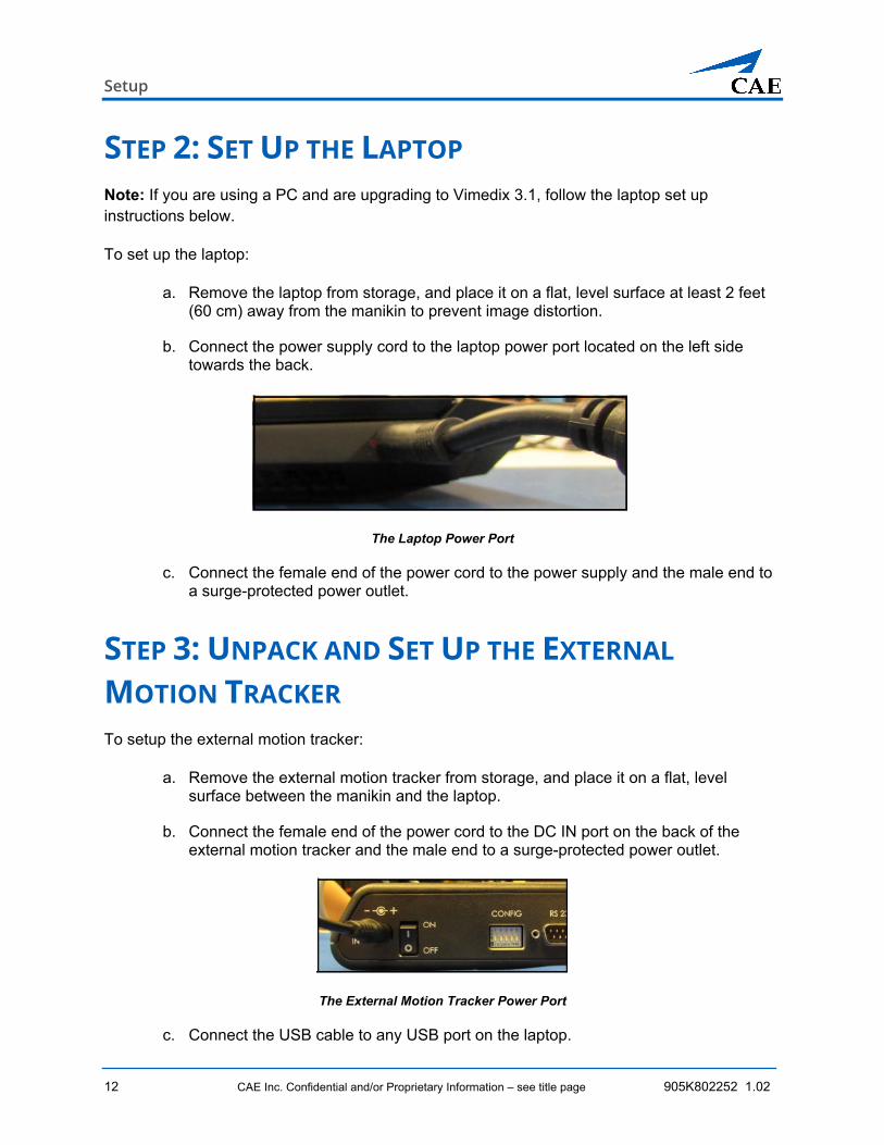
b. Connect the power supply cord to the laptop power port located on the left side towards the back.
The Laptop Power Port
c. Connect the female end of the power cord to the power supply and the male end to a surge-protected power outlet.
STEP 3: UNPACK AND SET UP THE EXTERNAL
MOTION TRACKER To setup the external motion tracker:
a. Remove the external motion tracker from storage, and place it on a flat, level surface between the manikin and the laptop.
b. Connect the female end of the power cord to the DC IN port on the back of the external motion tracker and the male end to a surge-protected power outlet.
The External Motion Tracker Power Port
c. Connect the USB cable to any USB port on the laptop.
CAEVimedix™
905K802252 1.2 CAE Inc. Confidential and/or Proprietary Information – see title page 13
d. Connect the other end to the port on the back of the external motion tracker.
The External Motion Tracker USB Port
STEP 4: CONNECT THE SIMULATOR HARDWARE To connect the simulator hardware:
a. Connect the manikin cable to the SOURCE port on the front panel of the external motion tracker.
The External Motion Tracker Source Port
b. Connect the probe cable to the SENSOR 1 port on the front panel of the external motion tracker.
WARNING: DO NOT connect the probe to the SENSOR 2 port. The probe must be connected to the SENSOR 1 port.
The Sensor Ports on the External Motion Tracker
Starting the Simulator
14 CAE Inc. Confidential and/or Proprietary Information – see title page 905K802252 1.02
STARTING THE SIMULATOR Once the Vimedix system is fully setup it is ready for use. Proceed with the following steps to start the simulator.
Steps for Starting the Simulator
1 Power on the Laptop and External Motion Tracker
2 Connect the Wireless Mouse (if necessary)
3 Launch the Vimedix Software
4 Update the Software (if applicable)
5 Accept the License Agreement
6 Calibrate the Probe
STEP 1: POWER ON THE LAPTOP AND EXTERNAL
MOTION TRACKER a. Select the ON/OFF switch on the external motion tracker to the ON position.
b. Select the power button on the Vimedix laptop to turn it on.
The Laptop Power Button (Left) and External Motion Tracker Power Switch (Right)
CAEVimedix™
905K802252 1.2 CAE Inc. Confidential and/or Proprietary Information – see title page 15
STEP 2: CONNECT THE WIRELESS MOUSE In the case that the Bluetooth connection is not automatic upon startup, a brief connection procedure must be performed.
To pair the wireless mouse with the laptop’s Bluetooth network:
a. Ensure the mouse is turned on and press the pairing button on the bottom of the mouse.
b. Click the Windows icon on the toolbar in the lower-left corner of the screen.
The Start panel appears.
c. Click the Settings (gear) icon on left side of the Start panel.
The Settings window appears.
Settings Window
d. Click Devices.
Starting the Simulator
16 CAE Inc. Confidential and/or Proprietary Information – see title page 905K802252 1.02
The Bluetooth and other devices window appears.
Bluetooth and Other Devices Window
e. Turn the Bluetooth toggle to the On position.
f. Click the Add Bluetooth or other device option.
CAEVimedix™
905K802252 1.2 CAE Inc. Confidential and/or Proprietary Information – see title page 17
The Add a device window appears.
Add a Device Window
g. Click the Bluetooth option.
The list of available Bluetooth-enabled devices appears.
h. Select the mouse from the list and click Connect.
The mouse is now connected to the laptop.
STEP 3: LAUNCH THE VIMEDIX SOFTWARE From the desktop, double-click on the CAE Vimedix icon to launch the Vimedix software.
The CAE Vimedix Icon
Starting the Simulator
18 CAE Inc. Confidential and/or Proprietary Information – see title page 905K802252 1.02
UPDATE NOTIFICATION Upon launching the Vimedix software, the program will search for a newer version of the software and prompt users to initiate an available update when it is detected.
Searching for newer version message
If a newer version of the software is detected, the Update Now screen will appear.
CAEVimedix™
905K802252 1.2 CAE Inc. Confidential and/or Proprietary Information – see title page 19
Click Update Now to initiate software update.
Starting the Simulator
20 CAE Inc. Confidential and/or Proprietary Information – see title page 905K802252 1.02
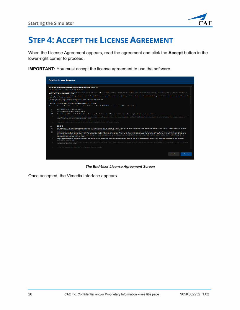
STEP 4: ACCEPT THE LICENSE AGREEMENT When the License Agreement appears, read the agreement and click the Accept button in the lower-right corner to proceed.
IMPORTANT: You must accept the license agreement to use the software.
The End-User License Agreement Screen
Once accepted, the Vimedix interface appears.
CAEVimedix™
905K802252 1.2 CAE Inc. Confidential and/or Proprietary Information – see title page 21
STEP 5: CALIBRATE THE PROBE As the system loads, and the display is configured, place the probe on the manikin’s chest or abdomen, as required. The Probe Calibration screen appears.
The Probe Calibration Screen
PROBE PLACEMENT FOR CALIBRATION To calibrate the probe:
a. Ensure that the probe is properly positioned: the probe should be placed in the center of the manikin’s chest with the sensory end pointing towards the head of the manikin.
Probe Placement on Male Manikin
Starting the Simulator
22 CAE Inc. Confidential and/or Proprietary Information – see title page 905K802252 1.02
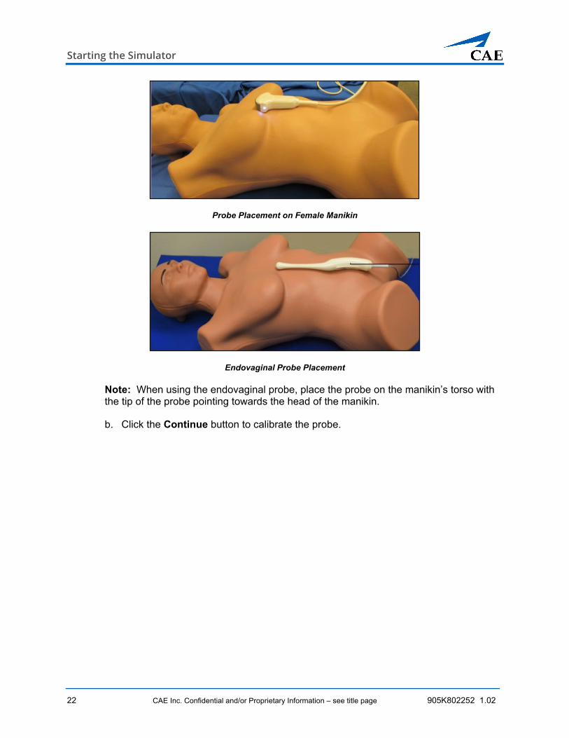
Probe Placement on Female Manikin
Endovaginal Probe Placement
Note: When using the endovaginal probe, place the probe on the manikin’s torso with the tip of the probe pointing towards the head of the manikin.
b. Click the Continue button to calibrate the probe.
CAEVimedix™
905K802252 1.2 CAE Inc. Confidential and/or Proprietary Information – see title page 23
USING THE SIMULATOR This portion of the document introduces you to the Vimedix 3.1 simulation environment. It describes the new user interface and the available features.
INTERFACE OVERVIEW The Vimedix simulator interface (simulation screen) consists of the Augmented Reality (AR) display, the Ultrasonography (US) display, and the Main toolbar which provides access to all of the functions and features available during a simulation. The interface displays either a preset view or a live simulation view. By default the interface displays a live view with a Split View layout, divided equally between AR and US displays.
In the upper-left corner of the interface is the Home button which opens the Menu page when selected. The Menu page houses controls for setting up and running the simulation and training sessions. The name of the currently loaded pathology is indicated in the upper-left corner beside the Home button.
In the lower portion of the screen, immediately below the displayed image are the ECG trace and heartrate indications. These are displayed by default and can be easily toggled on/off by clicking on the ECG trace icon at the far right side.
The Vimedix Simulator Interface
Using the Simulator
24 CAE Inc. Confidential and/or Proprietary Information – see title page 905K802252 1.02
AUGMENTED REALITY DISPLAY The Augmented Reality display is an interactive, animated 3D anatomical depiction of the organs and artifacts located in the scanned area. Structures and artifacts can be added or removed from view for learning purposes using the Visibility feature. Also, the AR view can be used to help learners identify the anatomical structures with the use of the Anatomy Labels feature. Each of these will be described in greater detail later in this guide.
During a simulation, the AR display includes a representation of the ultrasound beam placement to help the learner generate an accurate ultrasound image. The anatomy is displayed in cross-section, dependant on the beam position.
The AR Display
CAEVimedix™
905K802252 1.2 CAE Inc. Confidential and/or Proprietary Information – see title page 25
ULTRASONOGRAPHY DISPLAY The Ultrasonography (or ultrasound) image displays the anatomical structures scanned by the probe or preset views, as selected. Onscreen, the US image parameters are fully manipulable including a range of view options in 2D and 3D, image clarity, zoom, and so on, to provide a comprehensive learning environment. The features of the US display will be described in greater detail later in this guide.
The US Display
MAIN TOOLBAR The Main toolbar is located immediately below the simulation screen. It is available at all times when running a simulation. The Main toolbar provides controls for customizing the training experience. Buttons may be simple on/off toggle switches or may open secondary toolbars. The function of each button is provided in the following table.
The Main Toolbar
Note: The icons presented in the following table are the default versions for the Main toolbar. As selections are made, buttons may display a different icon. Refer to the Button Features section for more information.
Using the Simulator
26 CAE Inc. Confidential and/or Proprietary Information – see title page 905K802252 1.02
Main Toolbar Buttons
The Probe button pauses the probe and ultrasound beam position.
The Preset button opens a secondary toolbar with tabs. The tabs group the available preset views into anatomical categories. Refer to the Preset Toolbar section for more information.
The Visibility button allows you to choose which anatomical features are shown on the AR and Ultrasound displays. Selecting the button opens a secondary toolbar with tabs. Refer to the Visibility Toolbar section for more information.
The Layout button opens the Layout toolbar. It allows you to select among five possible configurations for the simulation screen. Refer to the Layout Toolbar section for more information.
The Link Views button activates/deactivates the linked views feature for the AR image. When the button is white the AR image is linked to the US image, this is the default setting. When the button is selected and turns blue, the AR image is unlinked and can be rotated and zoomed.
The Cross Section button opens a secondary toolbar with options for cross section views for 2D and 3D images. Refer to the Cross Section Toolbar section for more information.
The Beam button opens a secondary toolbar with controls for visual aids and US conventions. Refer to the Beam Toolbar section for more information.
The US Mode button opens the US Mode toolbar with 2D and 3D ultrasound selection options. The button icon will change to reflect the active mode. Refer to the US Mode Toolbar section for more information.
The M Mode button activates/deactivates the Motion Mode graph. When the button is selected and turns blue, the M Mode line becomes available and can positioned on the ultrasound for the desired M Mode reading.
The Doppler button opens a secondary toolbar with three Doppler selection options. The button icon will change to reflect the active mode. Refer to the Doppler Toolbar section for more information.
CAEVimedix™
905K802252 1.2 CAE Inc. Confidential and/or Proprietary Information – see title page 27
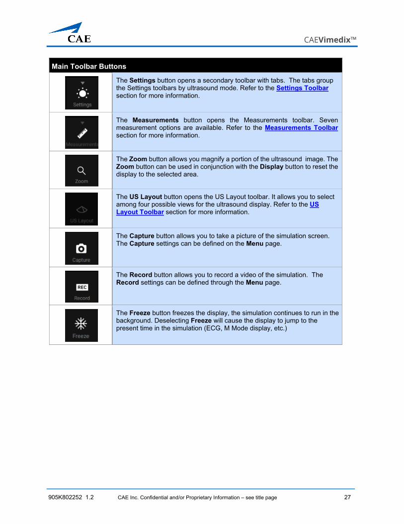
Main Toolbar Buttons
The Settings button opens a secondary toolbar with tabs. The tabs group the Settings toolbars by ultrasound mode. Refer to the Settings Toolbar section for more information.
The Measurements button opens the Measurements toolbar. Seven measurement options are available. Refer to the Measurements Toolbar section for more information.
The Zoom button allows you magnify a portion of the ultrasound image. The Zoom button can be used in conjunction with the Display button to reset the display to the selected area.
The US Layout button opens the US Layout toolbar. It allows you to select among four possible views for the ultrasound display. Refer to the US Layout Toolbar section for more information.
The Capture button allows you to take a picture of the simulation screen. The Capture settings can be defined on the Menu page.
The Record button allows you to record a video of the simulation. The Record settings can be defined through the Menu page.
The Freeze button freezes the display, the simulation continues to run in the background. Deselecting Freeze will cause the display to jump to the present time in the simulation (ECG, M Mode display, etc.)
Using the Simulator
28 CAE Inc. Confidential and/or Proprietary Information – see title page 905K802252 1.02
Button Features
Toolbar buttons are faded when the selection option is not available and appear bright when available. Once selected, the button turns blue or is highlighted by a blue overlay.
Button Selection Statuses
Buttons on the Main toolbar may display different icons to indicate which mode or feature is active. For example, the Mode icon will change depending on the mode chosen. This way the Main toolbar also acts as status bar, identifying what selections are active.
Main Toolbar segment displaying different US Mode Button Icons
Toolbar Features
The main toolbar is present at the bottom of the Simulation screen at all times. It provides access to all of the features that can be used during a practice or training session.
Secondary toolbars are opened by selecting buttons on the main toolbar. When opened, they will appear onscreen directly above the Main toolbar. The buttons that open secondary toolbars are: Preset, Visibility, Layout, Cross Section, Beam, US Mode, Doppler, Settings, Measurements and US Layout. The presence of secondary toolbars is indicated by the symbol ▼ above the button icon. When the toolbar is open, the symbol changes to ▲ to clearly indicate which button has opened the toolbar.
Some simulation features, such as Preset views and Visibility, require multiple secondary toolbars. These are grouped into tabs and are selectable by clicking on the tab name. Only one secondary toolbar is viewable at a time.
Once a secondary toolbar has been opened, simply reselect the button on the Main toolbar or click anywhere on the screen outside of the toolbar to close it again. If an option within the secondary toolbar is not selected, the toolbar will auto-collapse in 5 seconds.
Each of the secondary toolbars are described in greater detail in the following sections.
CAEVimedix™
905K802252 1.2 CAE Inc. Confidential and/or Proprietary Information – see title page 29
Preset Toolbars
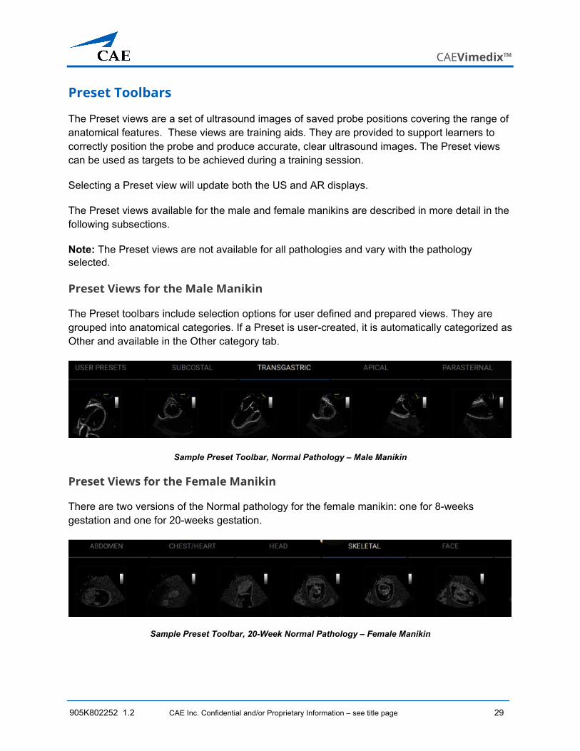
The Preset views are a set of ultrasound images of saved probe positions covering the range of anatomical features. These views are training aids. They are provided to support learners to correctly position the probe and produce accurate, clear ultrasound images. The Preset views can be used as targets to be achieved during a training session.
Selecting a Preset view will update both the US and AR displays.
The Preset views available for the male and female manikins are described in more detail in the following subsections.
Note: The Preset views are not available for all pathologies and vary with the pathology selected.
Preset Views for the Male Manikin
The Preset toolbars include selection options for user defined and prepared views. They are grouped into anatomical categories. If a Preset is user-created, it is automatically categorized as Other and available in the Other category tab.
Sample Preset Toolbar, Normal Pathology – Male Manikin
Preset Views for the Female Manikin
There are two versions of the Normal pathology for the female manikin: one for 8-weeks gestation and one for 20-weeks gestation.
Sample Preset Toolbar, 20-Week Normal Pathology – Female Manikin
Using the Simulator
30 CAE Inc. Confidential and/or Proprietary Information – see title page 905K802252 1.02
Visibility Toolbars
The Visibility toolbars provide a comprehensive set of selectable anatomical features. The anatomy can be displayed or removed from the display of the Augmented Reality and US images. The anatomy available is dependant on the pathology loaded.
Select or deselect an anatomical feature for display by clicking on it.
The Select All button on the AR Visibility and US Visibility toolbars allows you to rapidly select/deselect all of the available options. The button has three different phases of use which are explained below.
Select All Button
Allows you to select all of the available options if none are selected.
Allows you to select all of the remaining available options when some are already selected.
Allows you to deselect all of the options when all of the available options are selected.
The Visibility toolbars are described in greater detail in the following subsections.
Visibility Toolbars for the Male Manikin
For the male manikin (Bob 1.3), the Visibility options are grouped into three toolbars: AR Visibility, US Visibility and Options.
The AR Visibility toolbar provides the set of anatomical features visible in the AR display.
The AR Visibility Toolbar (Male Manikin)
CAEVimedix™
905K802252 1.2 CAE Inc. Confidential and/or Proprietary Information – see title page 31
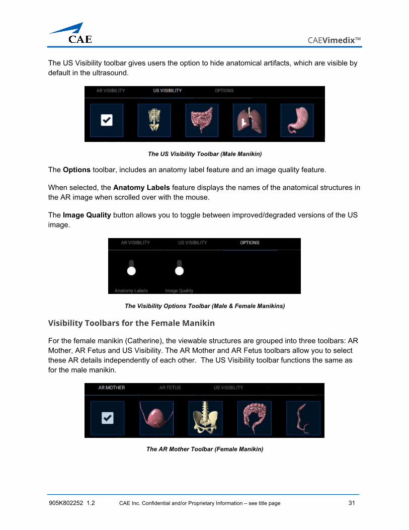
The US Visibility toolbar gives users the option to hide anatomical artifacts, which are visible by default in the ultrasound.
The US Visibility Toolbar (Male Manikin)
The Options toolbar, includes an anatomy label feature and an image quality feature.
When selected, the Anatomy Labels feature displays the names of the anatomical structures in the AR image when scrolled over with the mouse.
The Image Quality button allows you to toggle between improved/degraded versions of the US image.
The Visibility Options Toolbar (Male & Female Manikins)
Visibility Toolbars for the Female Manikin
For the female manikin (Catherine), the viewable structures are grouped into three toolbars: AR Mother, AR Fetus and US Visibility. The AR Mother and AR Fetus toolbars allow you to select these AR details independently of each other. The US Visibility toolbar functions the same as for the male manikin.
The AR Mother Toolbar (Female Manikin)
Using the Simulator
32 CAE Inc. Confidential and/or Proprietary Information – see title page 905K802252 1.02
The AR Fetus Toolbar (Female Manikin)
The Options toolbar is also present for the Female manikin with the same Anatomy Labels and Image Quality features as described in the previous section.
Layout Toolbar
The Layout toolbar allows you to choose how the simulation is displayed onscreen. There are options for Augmented Reality displayed alone, Ultrasound displayed alone and combined views. By default the images are displayed in 2D.
The Layout Toolbar
The function of each button is provided in the following table.
Layout Toolbar Buttons
Selecting the AR Only button displays a full screen view of the augmented reality image.
Selecting the Large AR button displays both AR and US views with AR occupying a larger portion of the screen.
Selecting the Split View button displays equally sized AR and US sides of the screen. The Split View is the default view.
Selecting the Large US button display both AR and US views with US occupying a larger portion of the screen.
Selecting the US Only button displays a full screen view of the ultrasonography image.
CAEVimedix™
905K802252 1.2 CAE Inc. Confidential and/or Proprietary Information – see title page 33
Cross Section Toolbar
Note: To use this feature, click the Link Views icon on the main toolbar to unlink the views.
Augmented reality cross section options are educational tools designed to allow learners to practice techniques in the absence of an instructor. The Cross Section feature, used in conjunction with the Visibility feature, allows learners to explore anatomical structures from virtually any perspective.
The Cross Section Toolbar
The buttons on the Cross Section toolbar are described in the following table.
Cross Section Toolbar Buttons
The None button removes any existing cross section view.
The Normal button sets the normal cross section view. This is the default setting. The AR cross section image will match the US display.
The Inverted button activates the inverted (opposite) view. The AR cross section image will be offset 180 degrees from the US display.
The 3D Volume button displays the cross section view for the 3D image. (3D mode must be active for this selection option to be available.)
The Plane 1 button selects the primary (default) cross section AR view. The plane is shaded green and corresponds to the ultrasound image outlined in green.
The Plane 2 button selects the secondary AR view, perpendicular to the primary view. The plane is shaded red and corresponds to the ultrasound image outlined in red.
The Plane 3 button selects the AR view for the 3D image. The plane is shaded blue and corresponds to the ultrasound image outlined in blue.
Using the Simulator
34 CAE Inc. Confidential and/or Proprietary Information – see title page 905K802252 1.02
Beam Toolbar
The Beam toolbar provides controls for the display of the ultrasound beam to assist the learner through the use of visual aids.
The Beam Toolbar
Each of the toolbar buttons are described in the following table.
Beam Toolbar Buttons
The Transparent button enables the transparent beam on the AR display. By default, the beam is set to transparent upon simulator start up.
The Edges button enables the transparent beam with a green border on the AR display.
The Ultrasound button enables the ultrasound mode of the beam, overlaying the ultrasound image directly on the AR display.
The Guide button enables a green line and a red line on the left and right sides of the ultrasound beam to indicate the orientation of the probe. The red line indicates the side of the probe with the blue light.
The Cardiac & Anesthesia button activates the Cardiac and Anesthesia convention display.
The Radiology button activates the Radiology convention display.
The Cardiac Pediatric button activates the Cardiac Pediatric convention display.
The Mayo Clinic Cardiac button activates the Mayo Clinic Cardiac convention display.
CAEVimedix™
905K802252 1.2 CAE Inc. Confidential and/or Proprietary Information – see title page 35
US Mode Toolbar
The Ultrasound Mode toolbar gives access to ultrasound features available for use during a simulation. Two 2D and two 3D options are available.
Note: The 3D features are not available for the Catherine manikin.
The US Modes Toolbar
Each button on the toolbar is described in the following table.
US Mode Toolbar Buttons
The Narrow 3D button allows you to view the selected region in 3D. (available with cardiac pathology only)
The Full Volume button allows you to view the selected region in 3D. (available with cardiac pathology only)
The Biplane button activates the Biplane mode and allows you to select a view based on either the primary or secondary ultrasound beam in 2D.
The 2D button displays the two-dimensional image.
Doppler Toolbar
The Doppler toolbar includes three Doppler mode selection options.
Doppler Toolbar Buttons
The CFD button activates the Colour Flow Doppler.
The PW button activates the Pulsed Wave Doppler.
Using the Simulator
36 CAE Inc. Confidential and/or Proprietary Information – see title page 905K802252 1.02
Doppler Toolbar Buttons
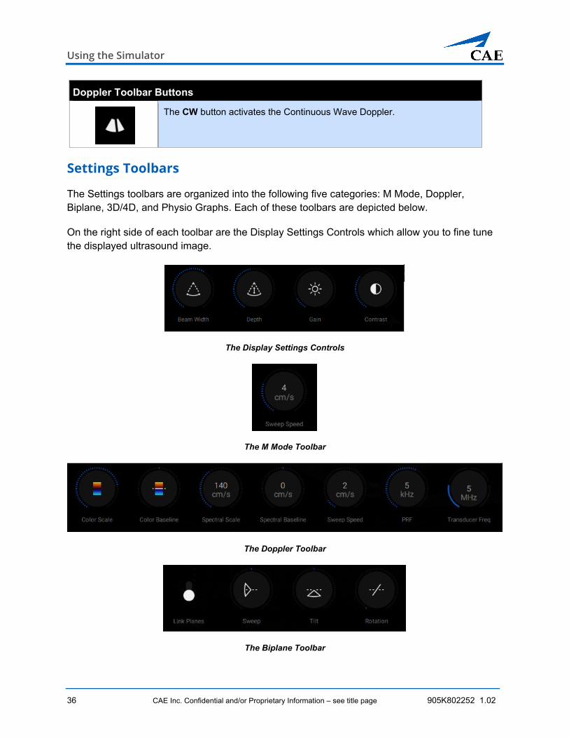
The CW button activates the Continuous Wave Doppler.
Settings Toolbars
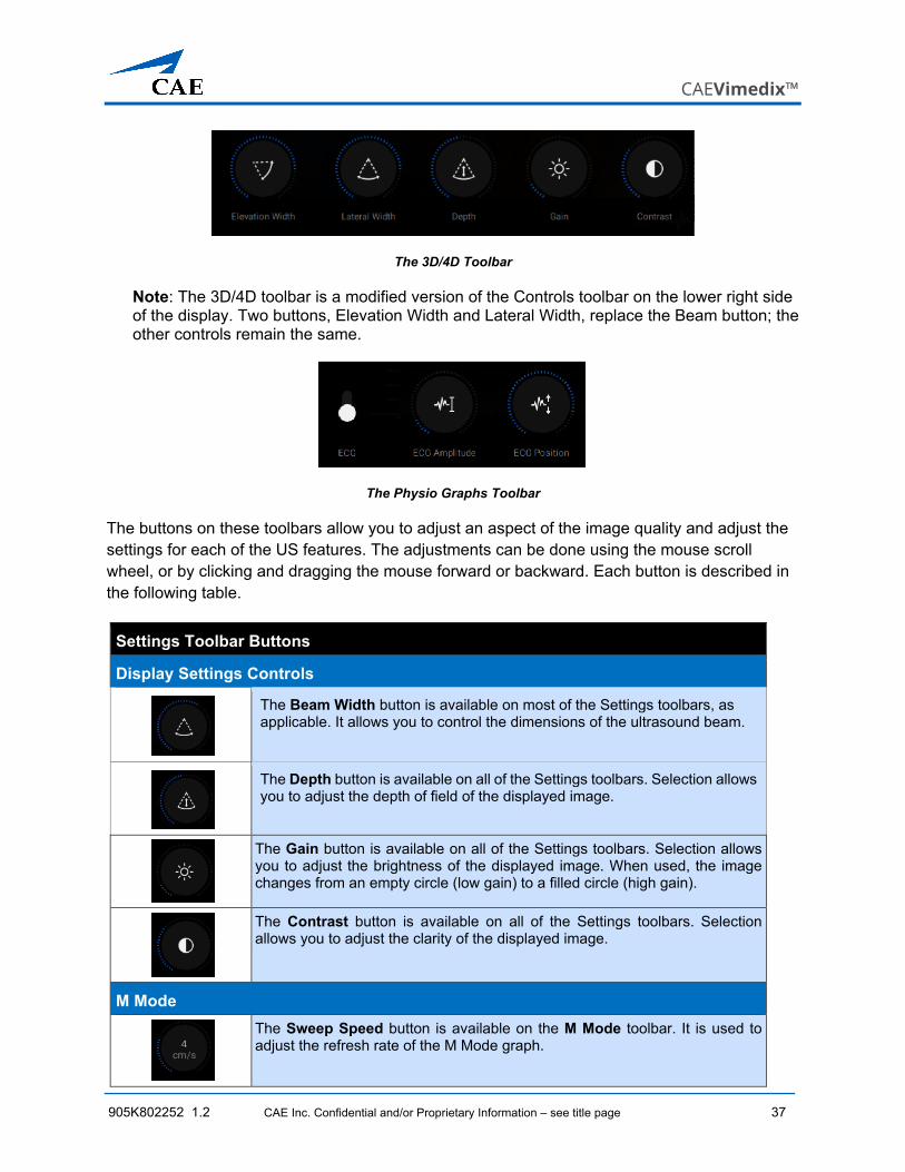
The Settings toolbars are organized into the following five categories: M Mode, Doppler, Biplane, 3D/4D, and Physio Graphs. Each of these toolbars are depicted below.
On the right side of each toolbar are the Display Settings Controls which allow you to fine tune the displayed ultrasound image.
The Display Settings Controls
The M Mode Toolbar
The Doppler Toolbar
The Biplane Toolbar
CAEVimedix™
905K802252 1.2 CAE Inc. Confidential and/or Proprietary Information – see title page 37
The 3D/4D Toolbar
Note: The 3D/4D toolbar is a modified version of the Controls toolbar on the lower right side of the display. Two buttons, Elevation Width and Lateral Width, replace the Beam button; the other controls remain the same.
The Physio Graphs Toolbar
The buttons on these toolbars allow you to adjust an aspect of the image quality and adjust the settings for each of the US features. The adjustments can be done using the mouse scroll wheel, or by clicking and dragging the mouse forward or backward. Each button is described in the following table.
Settings Toolbar Buttons
Display Settings Controls
The Beam Width button is available on most of the Settings toolbars, as applicable. It allows you to control the dimensions of the ultrasound beam.
The Depth button is available on all of the Settings toolbars. Selection allows you to adjust the depth of field of the displayed image.
The Gain button is available on all of the Settings toolbars. Selection allows you to adjust the brightness of the displayed image. When used, the image changes from an empty circle (low gain) to a filled circle (high gain).
The Contrast button is available on all of the Settings toolbars. Selection allows you to adjust the clarity of the displayed image.
M Mode
The Sweep Speed button is available on the M Mode toolbar. It is used to adjust the refresh rate of the M Mode graph.
Using the Simulator
38 CAE Inc. Confidential and/or Proprietary Information – see title page 905K802252 1.02
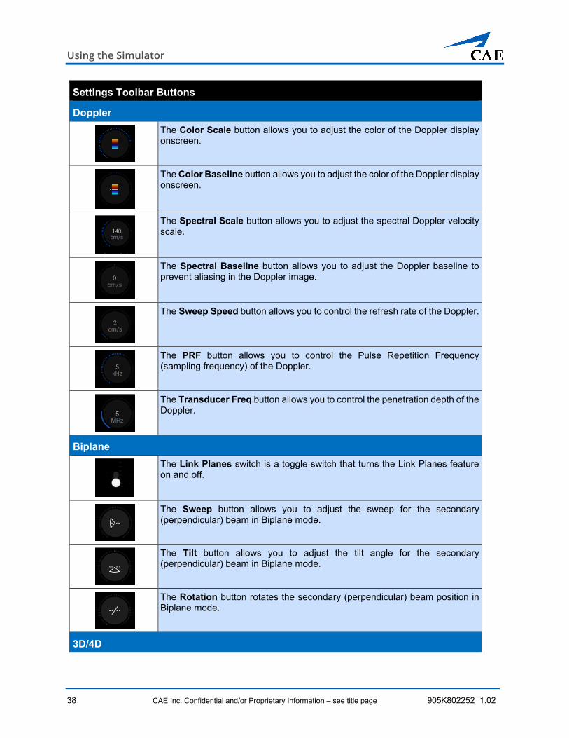
Settings Toolbar Buttons
Doppler
The Color Scale button allows you to adjust the color of the Doppler display onscreen.
The Color Baseline button allows you to adjust the color of the Doppler display onscreen.
The Spectral Scale button allows you to adjust the spectral Doppler velocity scale.
The Spectral Baseline button allows you to adjust the Doppler baseline to prevent aliasing in the Doppler image.
The Sweep Speed button allows you to control the refresh rate of the Doppler.
The PRF button allows you to control the Pulse Repetition Frequency (sampling frequency) of the Doppler.
The Transducer Freq button allows you to control the penetration depth of the Doppler.
Biplane
The Link Planes switch is a toggle switch that turns the Link Planes feature on and off.
The Sweep button allows you to adjust the sweep for the secondary (perpendicular) beam in Biplane mode.
The Tilt button allows you to adjust the tilt angle for the secondary (perpendicular) beam in Biplane mode.
The Rotation button rotates the secondary (perpendicular) beam position in Biplane mode.
3D/4D
CAEVimedix™
905K802252 1.2 CAE Inc. Confidential and/or Proprietary Information – see title page 39
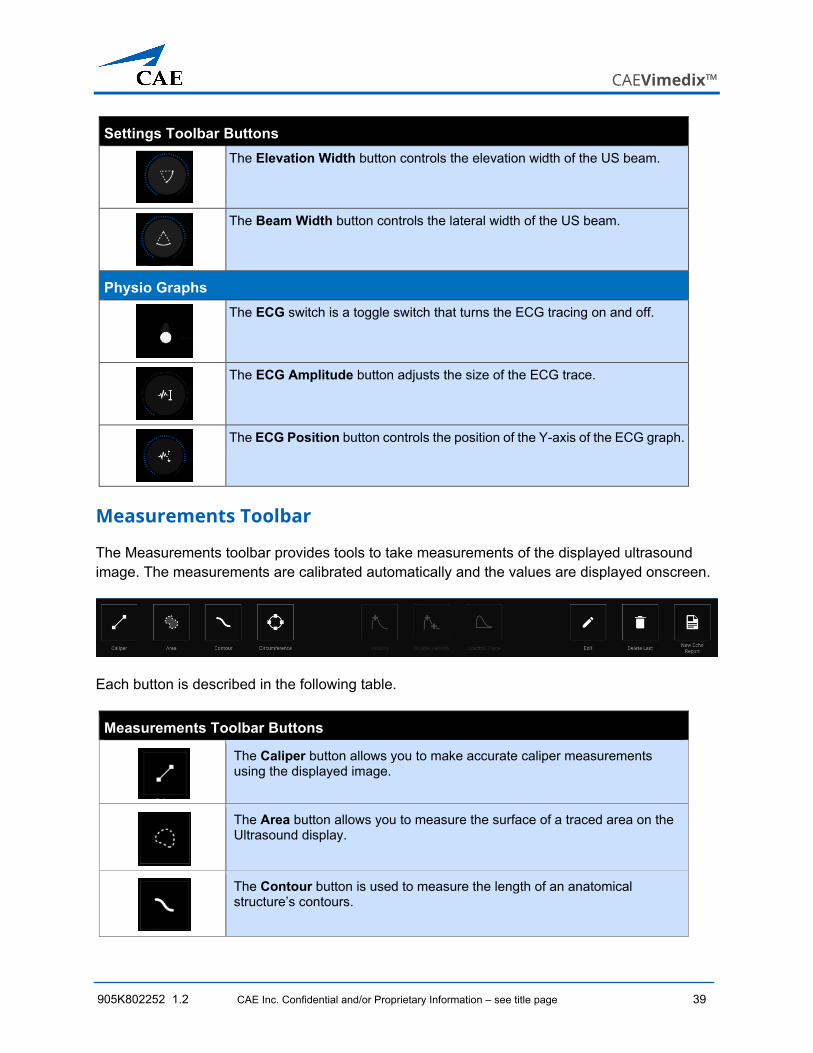
Settings Toolbar Buttons
The Elevation Width button controls the elevation width of the US beam.
The Beam Width button controls the lateral width of the US beam.
Physio Graphs
The ECG switch is a toggle switch that turns the ECG tracing on and off.
The ECG Amplitude button adjusts the size of the ECG trace.
The ECG Position button controls the position of the Y-axis of the ECG graph.
Measurements Toolbar
The Measurements toolbar provides tools to take measurements of the displayed ultrasound image. The measurements are calibrated automatically and the values are displayed onscreen.
Each button is described in the following table.
Measurements Toolbar Buttons
The Caliper button allows you to make accurate caliper measurements using the displayed image.
The Area button allows you to measure the surface of a traced area on the Ultrasound display.
The Contour button is used to measure the length of an anatomical structure’s contours.
Using the Simulator
40 CAE Inc. Confidential and/or Proprietary Information – see title page 905K802252 1.02
Measurements Toolbar Buttons
The Circumference button is used to measure an anatomical structure’s circumference.
The Velocity button allows you to take Pulse Wave and Continuous Wave velocity measurements.
The Double Velocity button allows you to take Pulse Wave and Continuous Wave velocity measurements and provides added calculations such as the Systolic/Diastolic ratio and Resistive Index.
The Spectral Trace button allows you to measure the wave of the PW and CW Doppler traces.
The Edit button allows you to adjust measurements that you have taken.
The Delete Last button removes the last measurement taken.
The New Echo Report button launches a template on the left side of the screen and allows users to access measurement tools to complete a new echo report on the Simulation screen.
US Layout Toolbar
The US Layout toolbar allows you to choose how the ultrasound image is displayed onscreen. There are four options ranging from a single 3D view to four 3D views.
Note: The 3D layouts are not available for the Catherine manikin.
The Layout Toolbar
The function of each button is provided in the following table.
CAEVimedix™
905K802252 1.2 CAE Inc. Confidential and/or Proprietary Information – see title page 41
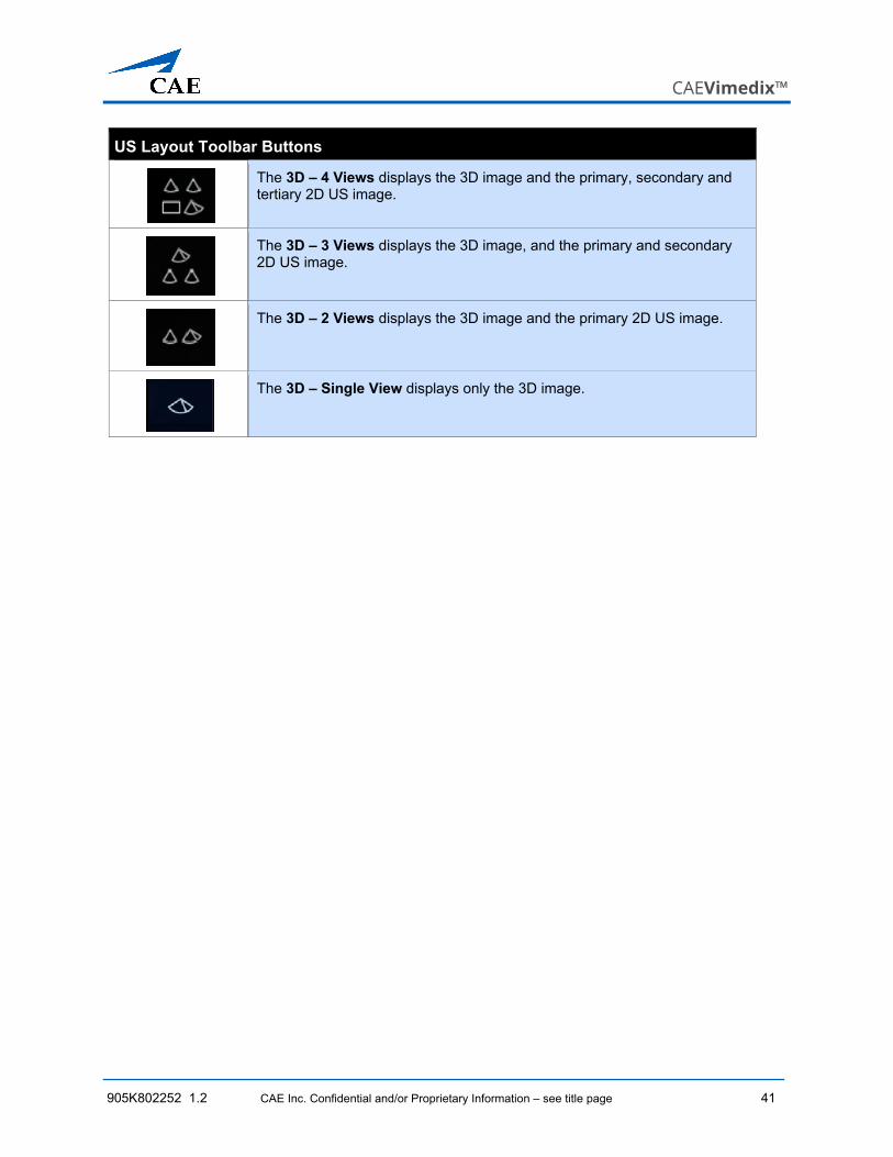
US Layout Toolbar Buttons
The 3D – 4 Views displays the 3D image and the primary, secondary and tertiary 2D US image.
The 3D – 3 Views displays the 3D image, and the primary and secondary 2D US image.
The 3D – 2 Views displays the 3D image and the primary 2D US image.
The 3D – Single View displays only the 3D image.
Using the Simulator
42 CAE Inc. Confidential and/or Proprietary Information – see title page 905K802252 1.02
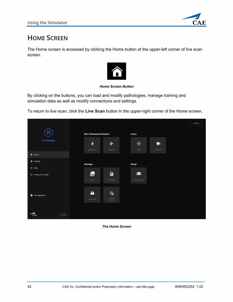
HOME SCREEN The Home screen is accessed by clicking the Home button at the upper-left corner of live scan screen.
Home Screen Button
By clicking on the buttons, you can load and modify pathologies, manage training and simulation data as well as modify connections and settings.
To return to live scan, click the Live Scan button in the upper-right corner of the Home screen.
The Home Screen
CAEVimedix™
905K802252 1.2 CAE Inc. Confidential and/or Proprietary Information – see title page 43
Each of the Menu page buttons are described in the following table.
Menu Page Buttons
The Normal Patient button is used to quickly start a simulation with default settings. The simulation will launch upon selection.
The Pathology button is used to access the list of available pathologies. When selected the Pathology screen is displayed containing more selection options.
Selecting the Training button opens the Training screen and gives access to the training modules available for selection.
Selecting the E-Learning button opens the ICCU Curriculum selection screen.
The Captures button provides access to the Manage Simulation Captures screen to browse and review the images and videos captured during a simulation. The capture settings for stills and video can also be defined here.
Selecting the Echo Reports button to create, view, reload, edit, delete and export Echo Reports in the Vimedix system.
Selecting the User Presets button to view and categorize the custom-created presets in the Vimedix system.
Selecting the Training Metrics button to view and manage the metrics used to evaluate training exercises in the Vimedix system.
Selecting the Motion Tracker button opens the Motion Tracker status screen which identifies the status of the Vimedix system elements.
Also available on the Menu page are the Settings and Quit Application icons, located in the lower-left corner.
Using the Simulator
44 CAE Inc. Confidential and/or Proprietary Information – see title page 905K802252 1.02
Selecting the Settings button opens the Settings screen. This screen allows you to select the default options for the simulator including display layout and ultrasound settings.
Selecting the Help button opens the Help menu. This screen contains support documents and links to online support information like websites and videos. FAQ is also included on this screen.
Selecting the Access Information button opens the client information screen and view access information for this license.
Selecting the Quit Application button closes the Vimedix user interface and shuts down the simulator.
CAEVimedix™
905K802252 1.2 CAE Inc. Confidential and/or Proprietary Information – see title page 45
SIMULATION OVERVIEW This section of the document provides instructions on how to use the complete range of Vimedix features to maximize the use of your device and optimize your training experience.
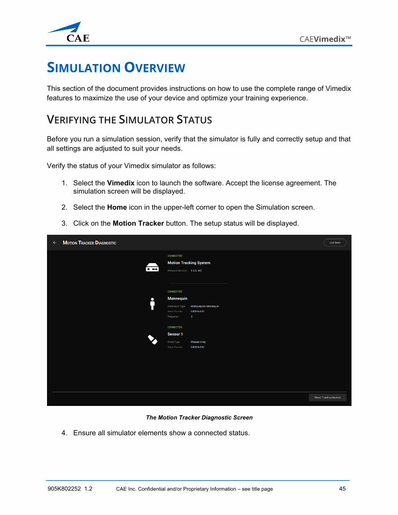
VERIFYING THE SIMULATOR STATUS Before you run a simulation session, verify that the simulator is fully and correctly setup and that all settings are adjusted to suit your needs.
Verify the status of your Vimedix simulator as follows:
1. Select the Vimedix icon to launch the software. Accept the license agreement. The simulation screen will be displayed.
2. Select the Home icon in the upper-left corner to open the Simulation screen.
3. Click on the Motion Tracker button. The setup status will be displayed.
The Motion Tracker Diagnostic Screen
4. Ensure all simulator elements show a connected status.
Using the Simulator
46 CAE Inc. Confidential and/or Proprietary Information – see title page 905K802252 1.02
MODIFYING THE DEFAULT SETTINGS It is possible to modify the default settings for the simulation to suit your preferences or training goals.
To modify the settings:
1. Navigate to the Home screen and select the Settings tab in the left sidebar. The Settings screen will open.
The Settings Screen
2. Adjust the settings as desired.
On the General tab:
a. Click the drop-down menu to select a language.
b. Manually enter the manikin used in the Patient Name field for the Simulator Generated Reports.
c. Select the desired layout option from the pull-down menu for the Image Settings.
d. Activate/deactivate the Use Pressure Sensor toggle switch. The switch will turn blue when the probe pressure sensor is enabled.
Note: The probe pressure sensor setting is updated automatically without having to exit and reload the software. It can be changed during a simulation session.
On the Probe tab:
CAEVimedix™
905K802252 1.2 CAE Inc. Confidential and/or Proprietary Information – see title page 47
a. Place the cursor in the field to modify values.
b. To revert to the default probe settings, click the Reset To Default button.
On the Capture tab:
a. In the Image Capture section, select the scope of captured views from the drop-down menu: All Interface, Augmented Reality, or Ultrasound.
b. In the Video Capture section, select the scope of captured views from the drop-down menu: All Interface, Augmented Reality, or Ultrasound.
c. Set the duration of the video by modifying the value of in the number field and selecting from the drop-down menu if the duration is based on heartbeats or seconds.
On the Training tab:
a. Use the toggle to enable or disable the Randomized Order feature.
b. Use the toggle to enable or disable Capture Metrics feature.
c. Use the toggle to enable or disable Show Reference image feature.
d. Use the toggle to enable or disable time limit and modify the value in the number field for the duration of the time limit in seconds.
3. Once all selections are made, click Home tab to return to the Home screen.
4. Click Quit Application in the left sidebar to exit the Vimedix application.
5. From the desktop, click the CAE Vimedix icon. The software will reload with the new default settings.
LOADING PATHOLOGIES Pathologies are cases provided to help learners recognize abnormalities in ultrasound images. They can be loaded for use in two different modes: Standard mode and Stealth mode. Standard mode allows you to view the pathology name and details; Stealth mode hides these details from view. To quickly launch a simulation session without specifying a particular pathology, you can select the Normal Patient option.
Using the Simulator
48 CAE Inc. Confidential and/or Proprietary Information – see title page 905K802252 1.02
Loading the Normal Patient Pathology
The Normal pathology is the default pathology of the simulator, it loads automatically when the simulator is started. If other pathologies are used during a simulation session, you can return to the Normal pathology by selecting the Normal Patient button on the Home screen.
The Normal Patient Button
The Normal pathology screen in Split View appears.
Normal Pathology Loaded
Loading a Pathology in Standard Mode
You can load pathologies in standard mode and organize the selections using the criteria of the Filter panel. The filters allow you to organize pathologies by Category or Availability or Package criteria, or by your own Custom filter criteria. The Custom filter feature allows users to create categories and add specific pathologies, which can be used by instructors for remote learning lecture development or as an organizational tool for learner. As each criteria is selected in the Filter list, the Pathologies list is updated accordingly.
CAEVimedix™
905K802252 1.2 CAE Inc. Confidential and/or Proprietary Information – see title page 49
If no filter criteria is selected, all available pathologies appear by default.
When a pathology is selected, the Details and Modalities are displayed in the right pane of the screen. You can toggle between the Details and Modalities information by clicking on the tabs.
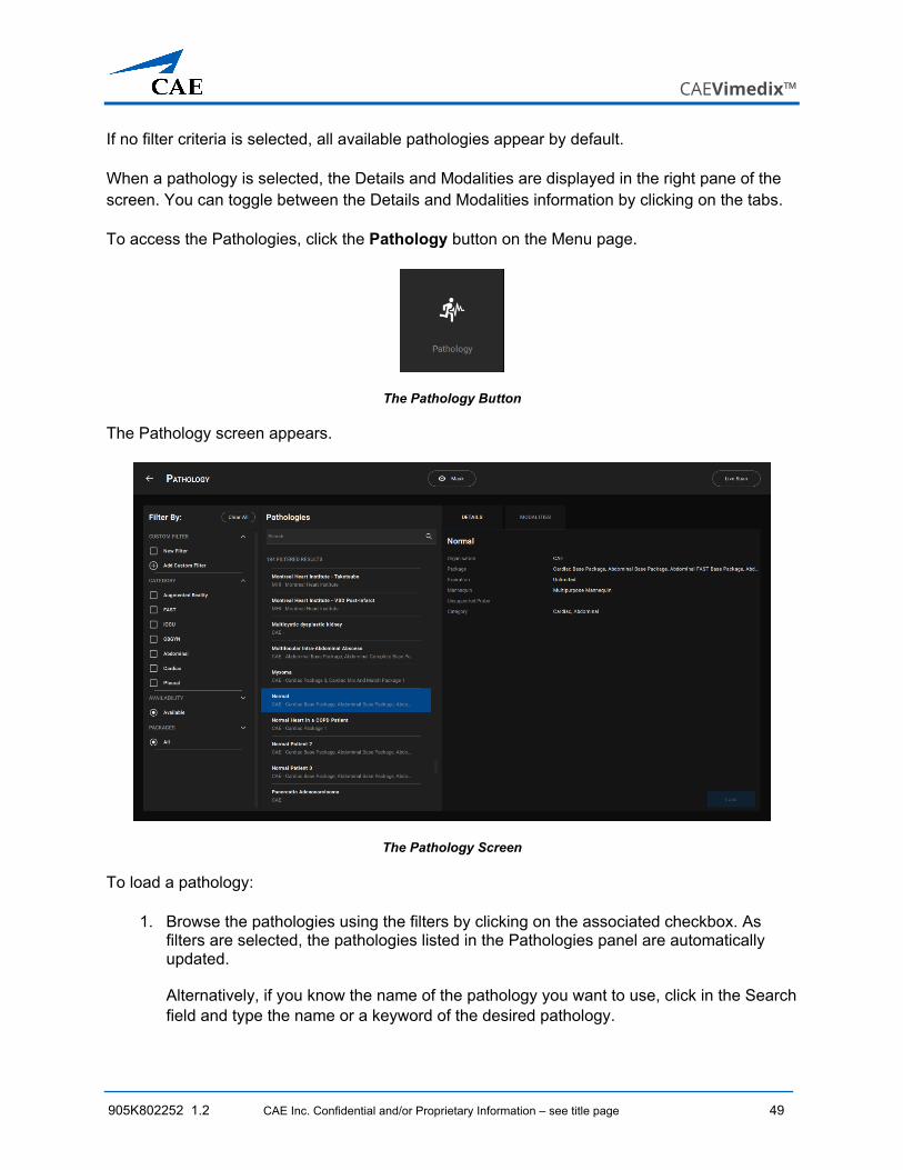
To access the Pathologies, click the Pathology button on the Menu page.
The Pathology Button
The Pathology screen appears.
The Pathology Screen
To load a pathology:
1. Browse the pathologies using the filters by clicking on the associated checkbox. As filters are selected, the pathologies listed in the Pathologies panel are automatically updated.
Alternatively, if you know the name of the pathology you want to use, click in the Search field and type the name or a keyword of the desired pathology.
Using the Simulator
50 CAE Inc. Confidential and/or Proprietary Information – see title page 905K802252 1.02
Pathology Panel Search Field
2. Click on the desired pathology name.
3. Review the pathology details and set the modalities, as needed.
a. Click on the Details or Modalities tabs to view their contents.
b. Review the details of the selected pathology.
c. Set the modalities by selecting from the available options in the pull-down menus.
The Modalities Window
4. Once the selections are done, click the Load button in the lower-right corner of the screen or in the Pathology name field.
The Load Button
CAEVimedix™
905K802252 1.2 CAE Inc. Confidential and/or Proprietary Information – see title page 51
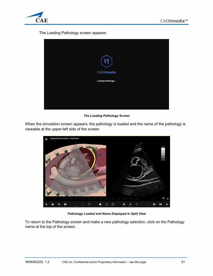
The Loading Pathology screen appears.
The Loading Pathology Screen
When the simulation screen appears, the pathology is loaded and the name of the pathology is viewable at the upper-left side of the screen
Pathology Loaded and Name Displayed in Split View
To return to the Pathology screen and make a new pathology selection, click on the Pathology name at the top of the screen.
Using the Simulator
52 CAE Inc. Confidential and/or Proprietary Information – see title page 905K802252 1.02
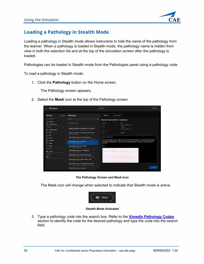
Loading a Pathology in Stealth Mode
Loading a pathology in Stealth mode allows instructors to hide the name of the pathology from the learner. When a pathology is loaded in Stealth mode, the pathology name is hidden from view in both the selection list and at the top of the simulation screen after the pathology is loaded.
Pathologies can be loaded in Stealth mode from the Pathologies panel using a pathology code.
To load a pathology in Stealth mode:
1. Click the Pathology button on the Home screen.
The Pathology screen appears.
2. Select the Mask icon at the top of the Pathology screen.
The Pathology Screen and Mask Icon
The Mask icon will change when selected to indicate that Stealth mode is active.
Stealth Mode Activated
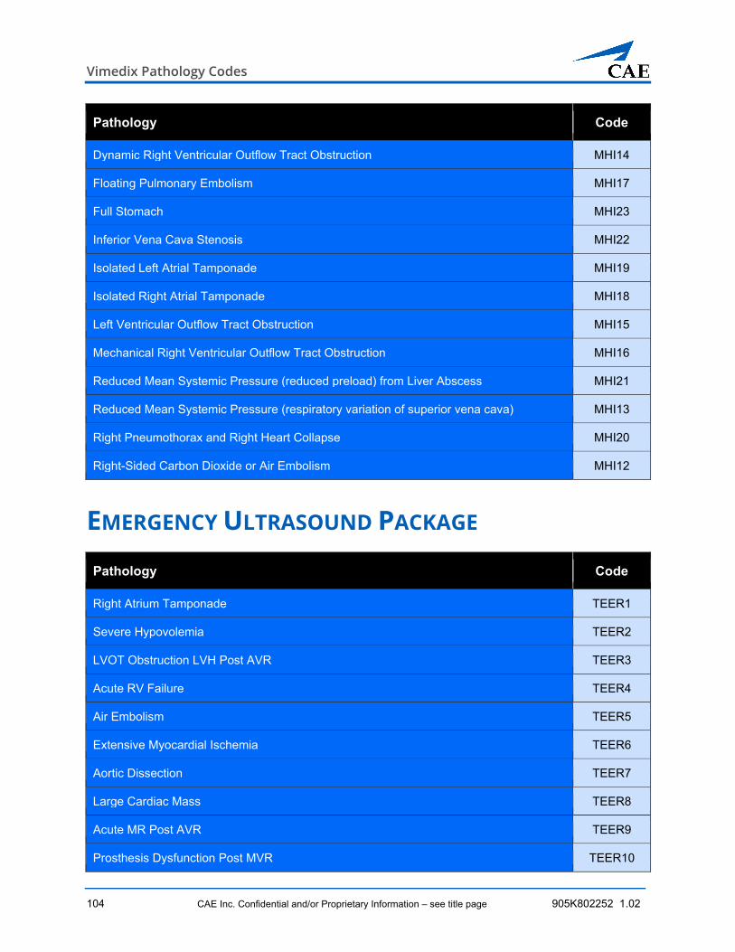
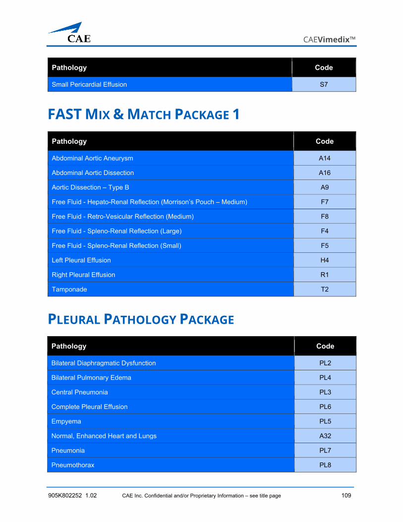
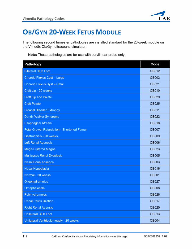
3. Type a pathology code into the search box. Refer to the Vimedix Pathology Codes section to identify the code for the desired pathology and type the code into the search field.
CAEVimedix™
905K802252 1.2 CAE Inc. Confidential and/or Proprietary Information – see title page 53
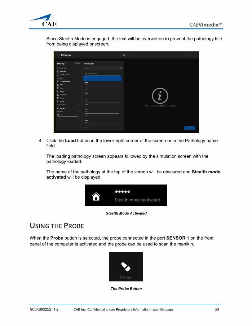
Since Stealth Mode is engaged, the text will be overwritten to prevent the pathology title from being displayed onscreen.
4. Click the Load button in the lower-right corner of the screen or in the Pathology name field. The loading pathology screen appears followed by the simulation screen with the pathology loaded. The name of the pathology at the top of the screen will be obscured and Stealth mode activated will be displayed.
Stealth Mode Activated
USING THE PROBE When the Probe button is selected, the probe connected in the port SENSOR 1 on the front panel of the computer is activated and the probe can be used to scan the manikin.
The Probe Button
Using the Simulator
54 CAE Inc. Confidential and/or Proprietary Information – see title page 905K802252 1.02
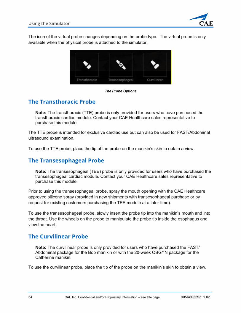
The icon of the virtual probe changes depending on the probe type. The virtual probe is only available when the physical probe is attached to the simulator.
The Probe Options
The Transthoracic Probe
Note: The transthoracic (TTE) probe is only provided for users who have purchased the transthoracic cardiac module. Contact your CAE Healthcare sales representative to purchase this module.
The TTE probe is intended for exclusive cardiac use but can also be used for FAST/Abdominal ultrasound examination.
To use the TTE probe, place the tip of the probe on the manikin’s skin to obtain a view.
The Transesophageal Probe
Note: The transesophageal (TEE) probe is only provided for users who have purchased the transesophageal cardiac module. Contact your CAE Healthcare sales representative to purchase this module.
Prior to using the transesophageal probe, spray the mouth opening with the CAE Healthcare approved silicone spray (provided in new shipments with transesophageal purchase or by request for existing customers purchasing the TEE module at a later time).
To use the transesophageal probe, slowly insert the probe tip into the manikin’s mouth and into the throat. Use the wheels on the probe to manipulate the probe tip inside the esophagus and view the heart.
The Curvilinear Probe
Note: The curvilinear probe is only provided for users who have purchased the FAST/ Abdominal package for the Bob manikin or with the 20-week OBGYN package for the Catherine manikin.
To use the curvilinear probe, place the tip of the probe on the manikin’s skin to obtain a view.
CAEVimedix™
905K802252 1.2 CAE Inc. Confidential and/or Proprietary Information – see title page 55
The Endovaginal Probe
Note: The endovaginal probe is only provided for users who have purchased the 8-week Ob/Gyn module.
Prior to using the endovaginal probe, spray the vaginal insert with the CAE Healthcare-approved silicone spray (provided in new shipments with 8-week module purchase or in vaginal insert installation kit).
The endovaginal probe can only be inserted into Catherine manikins with a vaginal insert present. If the manikin contains a vaginal plug instead of a vaginal insert, contact CAE Healthcare Customer Service to request a vaginal insert installation kit.
If a 20-week pathology is loaded when the endovaginal probe is connected, a message will appear onscreen stating that the incorrect probe is connected. The endovaginal probe is only compatible with the 8-week module normal case and pathologies.
USING THE PROBE PAUSE FEATURE The Probe Pause button only freezes the probe position in space and everything else functions as normal. The patient continues to animate normally and AR view can be manipulated. The probe pause feature is useful for:
• Anatomical orientation during trainings
• Analyzing cut planes
• Taking measurements for echo reports
• Obtaining captures
The Probe Pause Button
If the probe is paused prior to navigating to the Home screen, the paused probe position will resume upon returning to Normal Patient on the Simulation screen.
The paused probe position will also resume after a pathology, if it is paused prior to selecting a pathology. To resume a paused live scan from Pathology screen, click the Live Scan button in the upper-right corner of the screen.
Using the Simulator
56 CAE Inc. Confidential and/or Proprietary Information – see title page 905K802252 1.02
To reset the probe position, click the Probe button again until the Probe icon is visible to resume live scanning capabilities.
The Probe Button
USING PRESET VIEWS The Preset Views allow learners and instructors to have views saved for accessing desired views quickly and returning to a desired view at a later time. The views are created by users and can be categorized for easy cataloging. Any presets that are not assigned to a category appear in the Other category by default.
To access an existing preset, click the Preset button in the toolbar.
The Preset Button
To create a new preset:
1. From the toolbar, click the Preset button, and then click Add Preset.
The New Preset Review window appears.
The New Preset Review
CAEVimedix™
905K802252 1.2 CAE Inc. Confidential and/or Proprietary Information – see title page 57
2. Enter a name in the field and select a category (if desired).
3. Click Save.
To manage presets:
1. From the toolbar, click the Preset button, and then click Manage Presets.
The Manage User Presets screen appears.
The Manage User Presets Screen
2. From the Manage User Presets screen, select desired presets to load, edit, or delete.
To load, click Load.
To edit, click the pencil icon to edit the name or click the drop-down menu to change the category.
To delete:
a. Click the Manage button and select the desired preset.
b. Click the trash can icon.
c. When the Delete confirmation message appears, click Delete.
d. When finished, click Done.
Using the Simulator
58 CAE Inc. Confidential and/or Proprietary Information – see title page 905K802252 1.02
USING THE VISIBILITY FEATURE The Visibility toolbars allow you to choose to display or hide anatomical structures from view during a practice or training session. The AR and US views are modifiable independently of each other.
For the AR display, it is possible to select any single anatomical structure or combination thereof. For the US display, some structures cannot be removed from the view and are therefore not available on the US Visibility toolbar for selection.
To modify the set of anatomical structures visibile onscreen:
3. Click on the Visibility button located on the Settings toolbar.
The Visibility Button
The Visibility toolbar opens.
For the male manikin, the viewable structures are grouped into two toolbars: AR Visibility and US Visibility. You can select a toolbar by clicking on the tab label.
The Male Manikin Structures VisibilityToolbar – AR Visibility Tab
For the female manikin the viewable AR structures are organized into separate mother and fetus toolbars allowing independent selection of the visibility options. The US visibility elements are grouped together on a third toolbar.
CAEVimedix™
905K802252 1.2 CAE Inc. Confidential and/or Proprietary Information – see title page 59
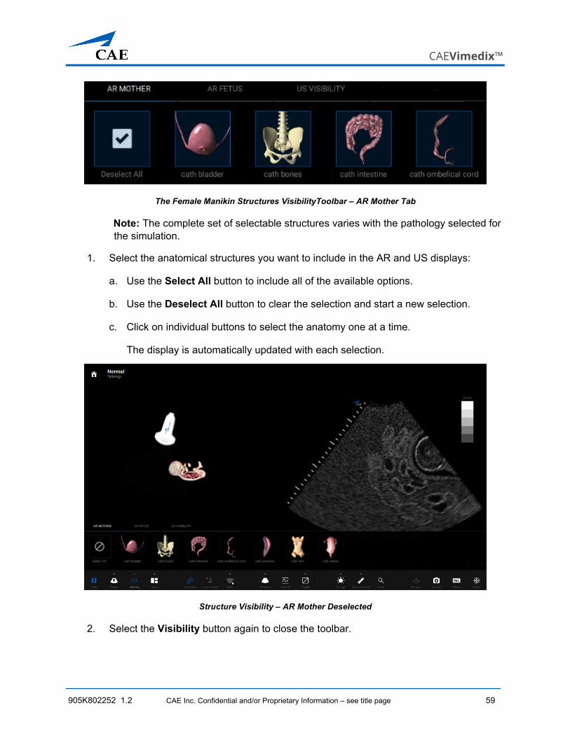
The Female Manikin Structures VisibilityToolbar – AR Mother Tab
Note: The complete set of selectable structures varies with the pathology selected for the simulation.
1. Select the anatomical structures you want to include in the AR and US displays:
a. Use the Select All button to include all of the available options.
b. Use the Deselect All button to clear the selection and start a new selection.
c. Click on individual buttons to select the anatomy one at a time.
The display is automatically updated with each selection.
Structure Visibility – AR Mother Deselected
2. Select the Visibility button again to close the toolbar.
Using the Simulator
60 CAE Inc. Confidential and/or Proprietary Information – see title page 905K802252 1.02
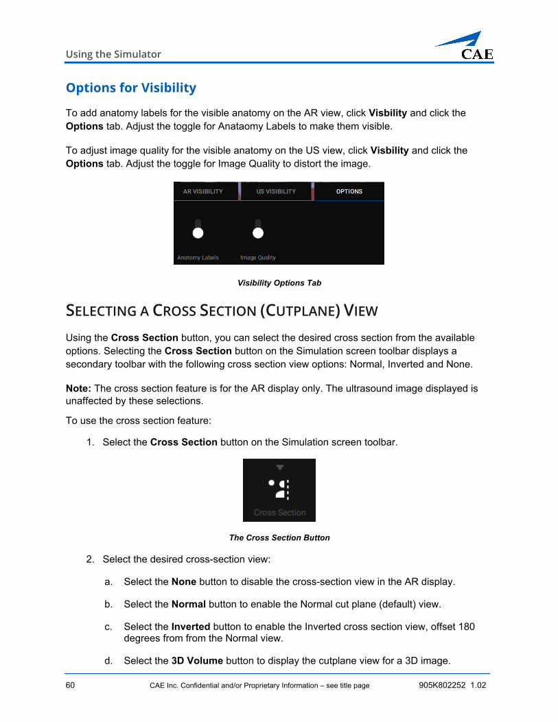
Options for Visibility
To add anatomy labels for the visible anatomy on the AR view, click Visbility and click the Options tab. Adjust the toggle for Anataomy Labels to make them visible.
To adjust image quality for the visible anatomy on the US view, click Visbility and click the Options tab. Adjust the toggle for Image Quality to distort the image.
Visibility Options Tab
SELECTING A CROSS SECTION (CUTPLANE) VIEW Using the Cross Section button, you can select the desired cross section from the available options. Selecting the Cross Section button on the Simulation screen toolbar displays a secondary toolbar with the following cross section view options: Normal, Inverted and None.
Note: The cross section feature is for the AR display only. The ultrasound image displayed is unaffected by these selections.
To use the cross section feature:
1. Select the Cross Section button on the Simulation screen toolbar.
The Cross Section Button
2. Select the desired cross-section view:
a. Select the None button to disable the cross-section view in the AR display.
b. Select the Normal button to enable the Normal cut plane (default) view.
c. Select the Inverted button to enable the Inverted cross section view, offset 180 degrees from from the Normal view.
d. Select the 3D Volume button to display the cutplane view for a 3D image.
CAEVimedix™
905K802252 1.2 CAE Inc. Confidential and/or Proprietary Information – see title page 61
Note: Only one view can be active at a time.
3. Select the desired plane: Plane 1, Plane 2, or Plane 3
The cross section feature can be used with the AR displaying all anatomical elements, or a subset.
USING THE BEAM VISUAL CUES The Beams button on the toolbar provides a number of options for supporting the learner in the simulation environment. Supports include ultrasound beam guides, a labeling feature for identifying anatomical structures in the AR image, and conventions for reorienting the US image.
To use the Visual Cues:
1. Select the Beams button on the toolbar.
The Beam Button
2. Select the desired visual aid by clicking on it.
Selecting the Ultrasound Beam
The selected beam determines how the ultrasound beam appears on the AR display. Click on the desired beam button to select the beam type.
The Beam Type Options
Using the Simulator
62 CAE Inc. Confidential and/or Proprietary Information – see title page 905K802252 1.02
The Transparent beam overlay is the default option.
A Transparent Beam Overlay
The Edges beam overlay is similar to the Transparent beam, but includes an outline around the edge of the ultrasound beam and a colored transparent overlay.
An Edges Beam Overlay
CAEVimedix™
905K802252 1.2 CAE Inc. Confidential and/or Proprietary Information – see title page 63
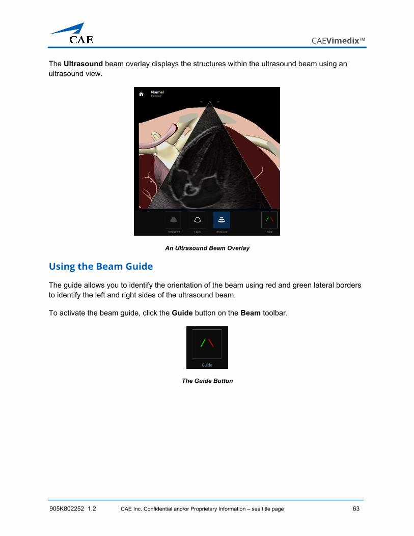
The Ultrasound beam overlay displays the structures within the ultrasound beam using an ultrasound view.
An Ultrasound Beam Overlay
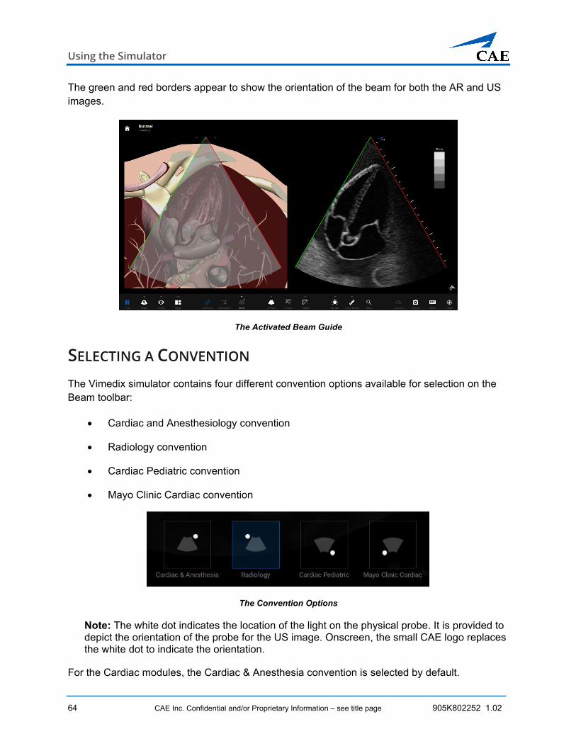
Using the Beam Guide
The guide allows you to identify the orientation of the beam using red and green lateral borders to identify the left and right sides of the ultrasound beam.
To activate the beam guide, click the Guide button on the Beam toolbar.
The Guide Button
Using the Simulator
64 CAE Inc. Confidential and/or Proprietary Information – see title page 905K802252 1.02
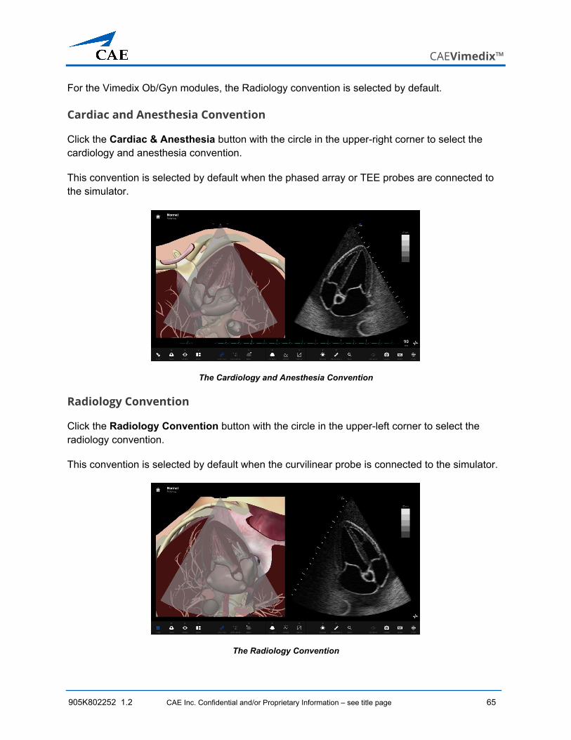
The green and red borders appear to show the orientation of the beam for both the AR and US images.
The Activated Beam Guide
SELECTING A CONVENTION The Vimedix simulator contains four different convention options available for selection on the Beam toolbar:
• Cardiac and Anesthesiology convention
• Radiology convention
• Cardiac Pediatric convention
• Mayo Clinic Cardiac convention
The Convention Options
Note: The white dot indicates the location of the light on the physical probe. It is provided to depict the orientation of the probe for the US image. Onscreen, the small CAE logo replaces the white dot to indicate the orientation.
For the Cardiac modules, the Cardiac & Anesthesia convention is selected by default.
CAEVimedix™
905K802252 1.2 CAE Inc. Confidential and/or Proprietary Information – see title page 65
For the Vimedix Ob/Gyn modules, the Radiology convention is selected by default.
Cardiac and Anesthesia Convention
Click the Cardiac & Anesthesia button with the circle in the upper-right corner to select the cardiology and anesthesia convention.
This convention is selected by default when the phased array or TEE probes are connected to the simulator.
The Cardiology and Anesthesia Convention
Radiology Convention
Click the Radiology Convention button with the circle in the upper-left corner to select the radiology convention.
This convention is selected by default when the curvilinear probe is connected to the simulator.
The Radiology Convention
Using the Simulator
66 CAE Inc. Confidential and/or Proprietary Information – see title page 905K802252 1.02
Cardiac Pediatric Convention
Click the Cardiac Pediatric Convention button with the circle in the lower-right corner to select the cardiac pediatric convention.
The Cardiac Pediatric Convention
Mayo Clinic Cardiac Convention
Click the Mayo Clinic Cardiac button with the circle in the lower-left corner to select the Mayo Clinic cardiac convention.
The Mayo Clinic Cardiac Convention
CAEVimedix™
905K802252 1.2 CAE Inc. Confidential and/or Proprietary Information – see title page 67
USING LINK VIEWS FEATURE The Link Views button is used to release and freeze the orientation of the AR image and is activated by default (indicated by the blue icon). Unlinking the view allows you to manipulate the orientation of the anatomy displayed for the AR image. Relocking the view fixes the orientation of the anatomy.
This feature can be used to adjust the orientaion of the anatomy to achieve targeted views during a practice or training exercise. You will also need to use the feature when using the Zoom (magnifying glass).
The Link Views Button (Activated)
To use the Link Views feature:
1. On the Simulation screen toolbar, click on the Link Views button. The icon will turn white to indicate that the views are no longer linked.
2. Using the mouse, manipulate the AR anatomy orientation, as needed.
3. Click the Link Views button again to relink the AR display.
CHANGING THE DISPLAY LAYOUT Selecting the Layout button on the simulation screen toolbar opens the secondary Layout toolbar with a number of selectable options for 2D and 3D views.
The Layout Button
The range of layout options allow you to change the display during the simulation to provide the desired training environment at all times. The Split View, which balances the display between equally sized AR and US images, is the default view presented at the start of a simulation.
Note: The default view can be modified by adjusting the settings on the Home screen.
The display will be updated immediately upon selection of any of the layout options.
Using the Simulator
68 CAE Inc. Confidential and/or Proprietary Information – see title page 905K802252 1.02
Selecting a 2D View Layout
To select a layout for a 2D image display:
1. Select the US Modes button on the Settings toolbar. Refer to the US Modes section for more information.
2. Select the 2D button.
3. Select the Layout button on the Settings toolbar. The Layout toolbar opens.
4. Select one of the options from the left side of the Layout toolbar.
The Layout Options
Each of the layouts are shown below.
The AR Only View
CAEVimedix™
905K802252 1.2 CAE Inc. Confidential and/or Proprietary Information – see title page 69
The Large AR View
The Split View
The Large US View
Using the Simulator
70 CAE Inc. Confidential and/or Proprietary Information – see title page 905K802252 1.02
The US Only View
Selecting a 3D View Layout
The three dimensional layout views provide a more comprehensive and manipulable set of views. The AR image is displayed as a 3D image and can be rotated around 6 DOF. The US image is also displayed as a 3D image and can be presented with additional cutplane views depicting the x, y, and z axes of the 3D image. Colored guide lines are provided for clarity to delineate each of the cutplanes.
Note: To use the 3D layouts, a 3D image must be active.
To select a layout for the three dimensional views:
1. Select the US Modes button on the Settings toolbar. Refer to the US Modes section for more information.
2. Select a US Modes option: Narrow 3D, Full Volume, Biplane, or 2D
3. Select the Layout button on the Settings toolbar. The Layout toolbar opens.
4. Select one of the 3D options from the right side of the Layout toolbar.
3D Layout Options (US Only Layout)
CAEVimedix™
905K802252 1.2 CAE Inc. Confidential and/or Proprietary Information – see title page 71
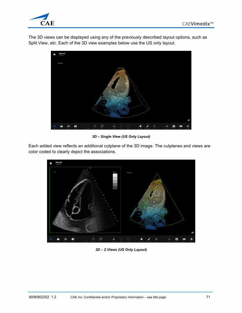
The 3D views can be displayed using any of the previously described layout options, such as Split View, etc. Each of the 3D view examples below use the US only layout.
3D – Single View (US Only Layout)
Each added view reflects an additional cutplane of the 3D image. The cutplanes and views are color coded to clearly depict the associations.
3D – 2 Views (US Only Layout)
Using the Simulator
72 CAE Inc. Confidential and/or Proprietary Information – see title page 905K802252 1.02
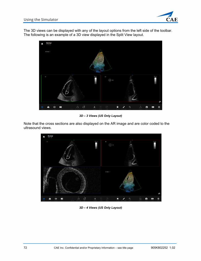
The 3D views can be displayed with any of the layout options from the left side of the toolbar. The following is an example of a 3D view displayed in the Split View layout.
3D – 3 Views (US Only Layout)
Note that the cross sections are also displayed on the AR image and are color coded to the ultrasound views.
3D – 4 Views (US Only Layout)
CAEVimedix™
905K802252 1.2 CAE Inc. Confidential and/or Proprietary Information – see title page 73
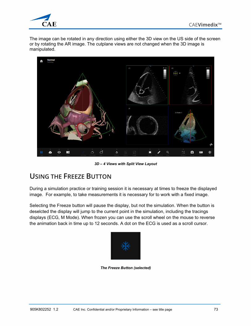
The image can be rotated in any direction using either the 3D view on the US side of the screen or by rotating the AR image. The cutplane views are not changed when the 3D image is manipulated.
3D – 4 Views with Split View Layout
USING THE FREEZE BUTTON During a simulation practice or training session it is necessary at times to freeze the displayed image. For example, to take measurements it is necessary for to work with a fixed image.
Selecting the Freeze button will pause the display, but not the simulation. When the button is deselcted the display will jump to the current point in the simulation, including the tracings displays (ECG, M Mode). When frozen you can use the scroll wheel on the mouse to reverse the animation back in time up to 12 seconds. A dot on the ECG is used as a scroll cursor.
The Freeze Button (selected)
Using the Simulator
74 CAE Inc. Confidential and/or Proprietary Information – see title page 905K802252 1.02
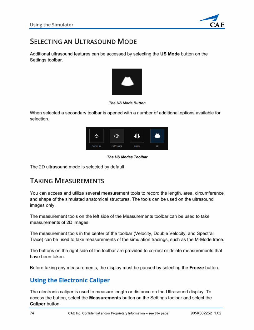
SELECTING AN ULTRASOUND MODE Additional ultrasound features can be accessed by selecting the US Mode button on the Settings toolbar.
The US Mode Button
When selected a secondary toolbar is opened with a number of additional options available for selection.
The US Modes Toolbar
The 2D ultrasound mode is selected by default.
TAKING MEASUREMENTS You can access and utilize several measurement tools to record the length, area, circumference and shape of the simulated anatomical structures. The tools can be used on the ultrasound images only.
The measurement tools on the left side of the Measurements toolbar can be used to take measurements of 2D images.
The measurement tools in the center of the toolbar (Velocity, Double Velocity, and Spectral Trace) can be used to take measurements of the simulation tracings, such as the M-Mode trace.
The buttons on the right side of the toolbar are provided to correct or delete measurements that have been taken.
Before taking any measurements, the display must be paused by selecting the Freeze button.
Using the Electronic Caliper
The electronic caliper is used to measure length or distance on the Ultrasound display. To access the button, select the Measurements button on the Settings toolbar and select the Caliper button.
CAEVimedix™
905K802252 1.2 CAE Inc. Confidential and/or Proprietary Information – see title page 75
To use the electronic caliper:
1. Select the caliper by clicking the Caliper button.
2. On the Ultrasound display, left-click the mouse at one extremity of the structure to be measured.
A + marker appears on the Ultrasound display in the place where the mouse is clicked.
Measurement Using Caliper Tool
3. Left-click the mouse again at the opposite extremity of the structure to be measured. Another + marker appears on the Ultrasound display in the place where the mouse is clicked. The measurement appears between the two markers.
Using the Area Measurement Tool
The area measurement tool is used to measure the surface of a traced area on the Ultrasound display. To access the button, select the Measurements button on the Settings toolbar and select the Area button.
To use the area measurement tool:
1. Select the Area button.
2. On the Ultrasound display, left-click the mouse at any point on the periphery of the area to be measured.
Using the Simulator
76 CAE Inc. Confidential and/or Proprietary Information – see title page 905K802252 1.02
A + marker appears on the Ultrasound display in the place where the mouse is clicked.
Measurement Using Area Tool
3. Using the mouse, trace the periphery of the area to be measured, returning to the starting point where the + marker appears.
4. After tracing back to the starting point, left-click the mouse. The traced area is selected, and the measurement is displayed in cm2.
Using the Contour Measurement Tool
The contour measurement tool is used to measure the length of an anatomical structure’s contours. To access the button, select the Measurements button on the Settings toolbar and select the Contour button.
To use the contour measurement tool:
1. Select the Contour button.
2. On the Ultrasound display, left-click the mouse at any point to begin measuring. A + marker appears on the Ultrasound display in the place where the mouse is clicked.
CAEVimedix™
905K802252 1.2 CAE Inc. Confidential and/or Proprietary Information – see title page 77
3. Using the mouse, trace the contour to be measured.
Measurement Using Contour Tool
4. After tracing the contour, left-click the mouse. The measurement is displayed in centimeters.
Using the Circumference Measurement Tool
The circumference measurement tool is used to measure an anatomical structure’s circumference. To access the button, select the Measurements button on the Settings toolbar and select the Circumference button.
To use the circumference measurement tool:
1. Select the Circumference button.
2. On the Ultrasound display, left-click the mouse at any point to begin measuring. A + marker appears on the Ultrasound display in the place where the mouse is clicked.
3. Left-click the mouse to mark the beginning point of the diameter.
Using the Simulator
78 CAE Inc. Confidential and/or Proprietary Information – see title page 905K802252 1.02
4. Move the mouse to expand the circumference to the desired area and left-click the mouse to capture the circumference measurement.
Measurement Using Circumference Tool
The measurement is displayed in centimeters.
Using the Velocity Measurement Tools
The Velocity and Double Velocity measurement tools are used to measure the speed of the trace peaks and valleys. To access the button, select the Measurements button on the toolbar and select either the Velocity button for a single measurement or the Double Velocity for a two-phase measurement and resultant calculations.
Note: The velocity measurement options are only enabled when the Pulsed Wave Doppler ultrasound mode is in use.
To use the velocity measurement tools:
1. Select the Freeze button to freeze the tracing generated by the active US mode.
2. Select the Velocity or Double Velocity button, as needed.
3. On the Ultrasound display, left-click the mouse at any point to begin measuring. A + marker appears on the Ultrasound display in the place where the mouse is clicked.
4. Left-click the mouse to mark the beginning point of the measurement.
CAEVimedix™
905K802252 1.2 CAE Inc. Confidential and/or Proprietary Information – see title page 79
5. Move the mouse to the desired area and left-click the mouse to capture the circumference measurement.
The measurement is displayed in centimeters.
Using the Spectral Trace Tool
The spectral trace measurement tool is used to measure the mean velocity. To access the button, select the Measurements button on the toolbar and select the Spectral Trace button.
Note: The Spectral trace option is only enabled when the Pulsed Wave Doppler ultrasound mode is in use.
To use the spectral trace measurement tool:
1. Select the Freeze button to freeze the tracing generated by the active US mode.
2. Select the Spectral Trace button.
3. On the Ultrasound display, left-click the mouse at any point to begin measuring. A + marker appears on the Ultrasound display in the place where the mouse is clicked.
4. Left-click the mouse to mark the beginning point of the diameter.
5. Move the mouse to expand the circumference to the desired area and left-click the mouse to capture the circumference measurement.
The measurement is displayed in centimeters.
Editing a Measurement
You are able to edit measurements which are taken incorrectly or need to be adjusted for accuracy.
Note: This feature is only available for the electronic caliper and circumference measurement tools.
To edit a measurement on the Ultrasound display:
1. Click the Edit button. The measurement points become squares, indicating that you can move the points as desired.
2. Adjust the points of the measurement and click in place to secure the point.
3. Upon finishing the measurement point adjustment, click the Measurements button or the selected measurement tool button to save the adjustment.
Using the Simulator
80 CAE Inc. Confidential and/or Proprietary Information – see title page 905K802252 1.02
Deleting a Measurement
Incorrect or unwanted measurements can be deleted at any time by selecting the Delete Last button. To delete the last measurement taken, click the Delete Last button. To delete all measurements, click the Delete button a second time.
CREATING AN ECHO REPORT Users are able to create new echo reports from the Measurements toolbar and obtain measurements for the report directly on the Simulation screen.
To create a new echo report:
1. Click the New Echo Report button.
The Echo Report template appears on the left side of the Simulation screen.
Echocardiography Report
2. Enter the patient information on Information tab.
3. Click Measurements tab to access measurement tools and obtain measurements.
• Hover over the double dash and click Measure to begin the measurement on the 2D image. The correct tool will automatically be selected. When the measurement is complete, the measurement will auto-full the field.
4. Click Contractability tab to access contraction measurement tools and obtain measurements.
CAEVimedix™
905K802252 1.2 CAE Inc. Confidential and/or Proprietary Information – see title page 81
5. Click Questions tab to complete questions for this ultrasound view.
6. Click Observations tab to enter observations for this ultrasound view.
7. Click Done in the upper-right corner when the report is complete.
Manage Echo Reports
To create, edit, export, or delete echo reports:
1. Navigate to the Home screen using the Home icon in the upper-right corner of the Simulation screen.
2. From the Home screen, click Echo Reports button.
The Manage Echo Reports screen appears.
Manage Echo Reports Screen
Create a Report
To create an echo report, click the plus icon in the lower-left corner of the Manage Echo Reports screen. An Echocardiography Report template will appear in the Simulation screen.
View, Edit or Load a Report
To view a report, select the desired report from the Reports list on the right side of the screen. The echo report information appears on the left side of the screen.
Using the Simulator
82 CAE Inc. Confidential and/or Proprietary Information – see title page 905K802252 1.02
To edit a report name, click the pencil icon to modify the name.
To load the echo report, click Load. A report’s content can only be modified or edited after the report is loaded.
Delete a Report
To delete a report:
a. Click Manage button.
b. Select desired echo report(s).
c. Click trash can icon to delete.
Export a Report
To export a report:
a. Select the desired echo report(s).
b. Click the export icon to export the echo report.
The Transfer on USB Key window appears.
Transfer On USB Key
c. Insert a USB into the laptop.
The USB key information will populate in the field.
d. Click Transfer.
Exit the Manage Echography Reports Screen
To return to the Home screen, click the back arrow in the upper-left corner of the screen.
To return to the Simulation screen, click Live Scan in the upper-right corner of the screen.
CAEVimedix™
905K802252 1.2 CAE Inc. Confidential and/or Proprietary Information – see title page 83
USING THE ZOOM (MAGNIFY) The Zoom feature allows learners to get closer view during a pathology to inspect anatomical features, identify anamolies, and measure with accuracy.
To use the Zoom feature:
1. Click the Zoom button in the toolbar.
2. Using the mouse (or mousepad on the laptop), hover the cursor over the center of the desired magnified area be and expand perimeter by hovering up or down, right or left.
3. Click once on the 2D image to set the magnified area selection.
The image appears magnified.
TAKING CAPTURES AND RECORDINGS The Vimedix software is capable of capturing screen images and recording video clips of simulator activity.
Capturing Images
To capture an image of the Vimedix interface, click the Screen Capture button or press the Print Screen key on the keyboard.
The Screen Capture Button
A capture of the current screen is taken and can be accessed by clicking the Captures button on the Home screen.
RECORDING VIDEO To record a video of simulator activity, click the Record button.
The Record Button
Using the Simulator
84 CAE Inc. Confidential and/or Proprietary Information – see title page 905K802252 1.02
The simulator activity is recorded for the length of time specified in the video capture settings or click the back arrow to stop recording. In addition to specifying the length of time for videos, you can specify whether to record the entire interface, the Ultrasound display only or the AR display only.
Modifying Image and Video Capture Settings
To modify image or video capture settings:
1. Navigate to the Home screen.
2. Select the Captures button. The Manage Simulation Captures screen will open.
3. Click the Gear icon in the upper-right corner of the Manage Simulation Captures screen The Captures Settings window appears.
The Capture Settings Window
4. Adjust the settings as needed.
a. For the Image Capture setting, identify the area of the screen to be captured by selecting from the pulldown window. You can choose among the options:
b. For the Video Capture setting, identify the area of the screen to be captured, the video capture duration (measured in time or heartbeats), and set the resolution for the image quality.
5. Select the Done button.
CAEVimedix™
905K802252 1.2 CAE Inc. Confidential and/or Proprietary Information – see title page 85
VIEWING IMAGE CAPTURES To view the image and videos:
1. Navigate to the Home screen.
2. Select the Captures button. The Manage Simulation Captures screen will open.
3. Select the desired image or recording to view in the display pane on the right side of the screen.
4. To return to the Home screen, click the back arrow in the upper-left corner of the screen. To return to the Live Scan, click the Live Scan button in the upper-right corner.
USING TRAINING TOOLS The Vimedix 3.1 software provides training tools for users to help them independently learn specific competencies and skills.
TRAINING Training exercises are included in the software and categorized by exercise types that represent the skills and competencies learners are required to learn.
To access the training exercises:
1. From the Home screen, click Training.
The Training Button
Using the Simulator
86 CAE Inc. Confidential and/or Proprietary Information – see title page 905K802252 1.02
The Training Exercises screen appears.
New Training Exercises Screen
2. Use filters to change available exercises based on probe type, mannequin type or exercise type.
3. Select a training exercise from results and click Start Training to load the training exercise.
Training Exercises Screen
The training exercise overview screen appears and displays the live scan as the learner is using the probe.
CAEVimedix™
905K802252 1.2 CAE Inc. Confidential and/or Proprietary Information – see title page 87
4. During the exercise, users can toggle between AR view or the Exercise View.
5. When multiple tasks are included in a training exercise, the user has the option to click Continue and move on to the next task.
The task ends when the time runs out or when the user clicks the Capture button, whichever comes first.
Training Exercises Screen
6. Click Retry to try a task again, if necessary.
7. When all tasks have been completed, the user can click End Exercise in the upper-right corner of the screen to end the exercise.
Using the Simulator
88 CAE Inc. Confidential and/or Proprietary Information – see title page 905K802252 1.02
Review Training Results
Once the training exercise is complete, the Result Summary window appears.
Result Summary Window
To save results, click Save.
To delete results, click Delete.
Manage Training Settings
To manage the training settings, from the Home screen, click Settings and select the Training tab.
The Training Settings screen appears.
Training Settings Screen
CAEVimedix™
905K802252 1.2 CAE Inc. Confidential and/or Proprietary Information – see title page 89
The metrics can be modified from this screen and applied to all training exercises when activated:
Randomize order: Randomizes the order of tasks within a training exercise for learners to complete.
Capture Metrics: Captures metrics during training exercise.
Show reference: Shows the reference image during a training exercise.
Time limit: Creates a time limit for completing tasks within the training exercise.
To access from Home screen, click Settings tab from the menu on the left side of the screen, and click Training tab.
Manage Training Metrics
From the Home screen, click Training Metrics.
The Training Metrics Button
The Manage Training Results screen appears.
Manage Training Results Screen
Using the Simulator
90 CAE Inc. Confidential and/or Proprietary Information – see title page 905K802252 1.02
View or Edit a Training Result Summary
To view a specific training result, select the desired training result from the Training Result list on the right side of the screen. The training result summary appears on the left side of the screen.
To edit a training result name, click the pencil icon.
Delete or Export Results
Click Manage to delete or export the results.
Manage Training Results Screen
To delete a result:
a. Select desired training result(s).
b. Click trash can icon to delete.
c. When the delete confirmation message appears, click Delete.
d. From the Manage Training Results screen, click Done.
To export a result:
a. Select desired training result(s).
b. Click the Export icon to export the training report.
CAEVimedix™
905K802252 1.2 CAE Inc. Confidential and/or Proprietary Information – see title page 91
The Transfer on USB Key window appears.
Transfer On USB Key
c. Insert a USB into the laptop.
The USB key information will populate in the field.
d. Click Transfer.
Exit the Manage Training Results Screen
To return to the Home screen, click the back arrow in the upper-left corner of the screen.
To return to the Simulation screen, click Live Scan in the upper-right corner of the screen.
Using the Simulator
92 CAE Inc. Confidential and/or Proprietary Information – see title page 905K802252 1.02
E-LEARNING The Vimedix simulator offers ICCU curriculum for learners to complete as part of the e-learning suite. How To videos are also available in the E-Learning portal when users scroll to the bottom of the training type list.
Learners can customize their content and course work from this e-learning portal.
To access the curriculum:
1. From the Home screen, click E-Learning.
The E-Learning Button
The ICCU Learning screen appears.
ICCU Learning Screen
CAEVimedix™
905K802252 1.2 CAE Inc. Confidential and/or Proprietary Information – see title page 93
2. Click on a desired training type. The available courses appear.
ICCU Learning Screen
3. Click on a desired course. The available modules appear. Press the play button to begin the module’s content.
ICCU Learning Screen
As modules and courses are completed, learners are able to use the knowledge to apply to their training exercises on the simulator.
Using Screen-Sharing Software
94 CAE Inc. Confidential and/or Proprietary Information – see title page 905K802252 1.02
USING SCREEN-SHARING SOFTWARE Users can download and utilize screen-sharing software on the laptop. Both browser and application-based screen sharing programs can be used in conjunction with the Vimedix software. Some of the more commonly used programs are:
• Microsoft Teams
• Google Meet
• Zoom
• Webex
To share the Vimedix software for a distance learning experience with remote learners, some preparation is required.
After the Vimedix software is launched, users can toggle to other programs on the laptop using the Windows key on the keyboard.
Windows Key
When the user presses the Window key, the Windows taskbar appears so other installed programs or Windows functions can be accessed.
Note: The Vimedix software will continue running in the background when users are accessing other programs or applications on the laptop.
How-to videos on using a screen-sharing software program on the laptop are also available in the Vimedix software.
To view the how-to videos in the Vimedix sofware:
4. Navigate to the Home screen by clicking the Home button in the upper-right corner of the live scan screen.
5. Click the Help button on the Home screen
6. Click the How-to Videos button.
CAEVimedix™
905K802252 1.2 CAE Inc. Confidential and/or Proprietary Information – see title page 95
DOWNLOADING THE SCREEN-SHARING SOFTWARE Screen-sharing software is not installed upon shipment of the laptop and it is not installed from completing the Vimedix software upgrades. User need to download and install the software for screen-sharing applications that are not browser based.
To download a screen-sharing software program:
1. If the Vimedix software is launched, use the Windows key on the keyboard to
2. From the desktop, click the Chrome icon to launch the Chrome browser.
3. Visit the program’s website and locate the download instructions.
4. Follow the prompts to download.
5. When the file is downloading, follow the prompt to execute the installation process. This may take several minutes and could require the user to restart the laptop.
Once the software is installed, you can access the software as described in the following section.
For browser-based, screen-sharing programs such as Google Meet, see the Accessing the Software section.
Note: Some of the desktop application programs also have browser-based options. See the program’s website for more information about launching in a browser.
ACCESSING THE SCREEN-SHARING SOFTWARE When Vimedix is launched, there are two ways to access a screen-sharing software program via the Chrome browser or the desktop application (if downloaded onto the laptop).
To access the screen-sharing software via browser:
1. If the Vimedix software is running, press the Windows key. The Windows task bar appears.
2. Enter Chrome in the Search bar and select Chrome from the search results.
The Chrome browser launches.
3. If accessing the program through an email link, enter email portal web address into the web address bar in browser and press Enter key on the keyboard. Locate email and click link in email to open web-based browser program.
Using Screen-Sharing Software
96 CAE Inc. Confidential and/or Proprietary Information – see title page 905K802252 1.02
If accessing the program without emailed link, enter the program website into the web address bar in browser. Login to program website and locate meeting or initiate meeting. Invite attendees (as necessary).
4. Select Share Screen option for the meeting. This feature may only be available if the user with Vimedix software is the host.
To access the screen-sharing software via desktop application:
1. If the Vimedix software is running, press the Windows key. The Windows task bar appears.
2. Enter the application name into the Search bar and select the application from the search results.
The application launches.
3. Login to the application and initate meeting. Invite attendees (as necessary).
SHARING CONTROL OF VIMEDIX SOFTWARE Screen-sharing programs allow users to share control of the Vimedix software and gives remote learners the ability to navigate through the software along with their instructors.
Users with shared control can access main toolbar functions such as selecting a preset, completing Echo Reports, taking measurements, changing views, initiating dopplers and modifying cross sections.
Note: Remote learners can only manipulate virtual probe in a selected Preset, not live scan.
To provide users with the optimal view during demonstrations, instructors can click the Link View button in the main toolbar and unlink the images to zoom out on the AR image using the mouse scroll wheel, to help the learners see the probe’s orientation and location on the patient.
For more information on the remote learner and distance learning capabilities, click the How To Videos icon in the Help screen.
CAEVimedix™
905K802252 1.2 CAE Inc. Confidential and/or Proprietary Information – see title page 97
KEYBOARD AND MOUSE USAGE
KEYBOARD SHORTCUTS Shortcut Key Action
Shift + Esc Exit - Shuts down the simulator
Esc Change Screen – Toggles between Simulation screen and Menu pages
Tab List Pathologies – Opens the Pathology menu to load pathologies
PRT SCRN / Print Screen
Screen Capture – Takes a screen capture.
Home Training - Opens the Training menu
Space bar Pause/Unpause - Freezes or unfreezes the display image
Enter Stop - Stops current training session
↑ Increase Contrast - Increases contrast on the Ultrasound display
↓ Decrease Contrast - Decreases contrast on the Ultrasound display
→ Increase Gain - Increases gain on the Ultrasound display
← Decrease Gain - Decreases gain on the Ultrasound display
Backspace Delete Measurement - Deletes the last measurement taken
Page Up Increase Heart Rate - Increases heart rate by 5 beats per minute (bpm)
Page Down Decrease Heart Rate - Decreases heart rate by 5 beats per minute (bpm)
+ and/or - Depth of Field - Increases or decreases the depth of field
A Area Measurement - Activates or deactivates the area measurement feature
B M Mode Settings – Opens the Physio settings menu
C Electronic Caliper - Activates or deactivates the electronic caliper
D Color Doppler - Activates or deactivates color Doppler
E Convention - Changes the ultrasound imaging convention (marker position). By default, the cardiology and anesthesiology convention is used
Keyboard and Mouse Usage
98 CAE Inc. Confidential and/or Proprietary Information – see title page 905K802252 1.02
Shortcut Key Action
F Record Video - Records video of the current display.
G Zoom - Activates or deactivates the zoom feature. When zoom is active, use the mouse to adjust the position of the region of interest, then click the left mouse button to select the region of interest to enlarge.
H Status - Opens the Tracker page
K ECG - Displays or hides ECG tracing
L Circumference Measurement - Activates or deactivates the circumference measurement feature.
M M Mode - Activates or deactivates M mode
O Visibility - Opens the Visibility menu
P Planes - Changes the cutplane direction in the AR view. This function is relevant when Link Views is disabled
Q Manage Captures - Opens the simulation Captures window where screen and video captures can be viewed and managed
S PW Doppler - Toggles the Pulsed Wave Doppler on/off
T Tutorial - Activates or deactivates tutorial mode
V Size - Toggles through the layout options for the AR and Ultrasound displays
W CW Doppler - Toggles the Continuous Wave Doppler on/off
X Link Views - Activates or deactivates the linked views between the AR and US
Y Beam Type - Toggles between beam types
Z Settings - Opens the Settings window where system settings can be modified
8 Increase Doppler Range - Increases Doppler range
2 Decrease Doppler Range - Decreases Doppler range
905K802252 1.2 CAE Inc. Confidential and/or Proprietary Information – see title page 99
MOUSE CONTROLS
Action Mouse Control
Zoom in or out Click and hold the mouse wheel, then move the mouse while still holding the wheel.
Adjust depth of field Roll the mouse wheel backward or forward.
Move the organs Press and hold the left mouse button and move the mouse to drag the organs. The ultrasound beam does not move, but the ultrasound image changes because the organs move within the scanning plane.
Move the probe With Link Views turned off, press and hold the left mouse button in the AR display and move the mouse. The ultrasound image changes because the scanning plane moves.
Move the organs and probe With Link Views turned off, simultaneously press and hold the left and right mouse buttons in the AR display and move the mouse. The ultrasound image does not change, because the probe and beam do not move in relation to the body.
Vimedix Pathology Codes
100 CAE Inc. Confidential and/or Proprietary Information – see title page 905K802252 1.02
VIMEDIX PATHOLOGY CODES Pathologies can be loaded in Stealth mode using codes so that the pathology names are not visible to learners. The available pathology codes are listed in the following tables.
TTE OR TEE CARDIAC MODULES Pathology Code
Dilated Cardiomyopathy - Severe Biventricular Systolic Dysfunction D2
Hyperdynamic Left Ventricular Systolic Function A4
Mechanical Prosthetic Valve (Bileaflet) in Aortic and Mitral Position J2
Myxoma M1
Pulmonary Hypertension P1
Tamponade T2
MONTREAL HEART INSTITUTE (MHI)
Pathology Code
Montreal Heart Institute - Amyloidosis MHI1
Montreal Heart Institute - CMP – Dilated MHI2
Montreal Heart Institute - CMP - Hypertrophic MHI3
Montreal Heart Institute - Ebstein's Anomaly - ASD MHI4
Montreal Heart Institute - LV Apical Thrombus MHI5
Montreal Heart Institute - Mitral Valve Prolapse MHI6
Montreal Heart Institute - Mitral Valve - Rheumatic Disease MHI7
Montreal Heart Institute - Myxoma MHI8
Montreal Heart Institute - Takotsubo MHI9
Montreal Heart Institute - VSD (CIV) Post-Infarct MHI10
MONTREAL HEART INSTITUTE (MHI) ACUTE
COMPLEX PATHOLOGY+
Pathology Code
Abdominal Compartment Syndrome MHI11
Vimedix Pathology Codes
104 CAE Inc. Confidential and/or Proprietary Information – see title page 905K802252 1.02
Pathology Code
Dynamic Right Ventricular Outflow Tract Obstruction MHI14
Floating Pulmonary Embolism MHI17
Full Stomach MHI23
Inferior Vena Cava Stenosis MHI22
Isolated Left Atrial Tamponade MHI19
Isolated Right Atrial Tamponade MHI18
Left Ventricular Outflow Tract Obstruction MHI15
Mechanical Right Ventricular Outflow Tract Obstruction MHI16
Reduced Mean Systemic Pressure (reduced preload) from Liver Abscess MHI21
Reduced Mean Systemic Pressure (respiratory variation of superior vena cava) MHI13
Right Pneumothorax and Right Heart Collapse MHI20
Right-Sided Carbon Dioxide or Air Embolism MHI12
EMERGENCY ULTRASOUND PACKAGE
Pathology Code
Right Atrium Tamponade TEER1
Severe Hypovolemia TEER2
LVOT Obstruction LVH Post AVR TEER3
Acute RV Failure TEER4
Air Embolism TEER5
Extensive Myocardial Ischemia TEER6
Aortic Dissection TEER7
Large Cardiac Mass TEER8
Acute MR Post AVR TEER9
Prosthesis Dysfunction Post MVR TEER10
CAEVimedix™
905K802252 1.02 CAE Inc. Confidential and/or Proprietary Information – see title page 105
ABDOMINAL BASE MODULE
Pathology Code
Normal A3
Normal, Patient 2 A32
Normal, Patient 3 A33
Free Fluid - Hepato-Renal Reflection (Morrison's Pouch - Small) F1
Free Fluid - Retro-Vesical Reflection (Large) F3
Free Fluid - Spleno-Renal Reflection (Medium) F2
Hydatid Cyst of the Liver H5
Liver Hepatocellular Carcinoma Hypoechoic L5
Multilocular Intra-Abdominal Abscess M2
ABDOMINAL PACKAGE 1
Pathology Code
Acute Cholecystitis C11
Angiomyolipoma A19
Bacterian Hepatic Abscess B5
Cholecystitis with Gallstone C10
Choledocolithiasis C13
Exophytic Renal Cyst E1
Hepatomegaly L3
Kidney Stones K12
Pancreatic Pseudocyst P2
Splenomegaly S4
Vimedix Pathology Codes
106 CAE Inc. Confidential and/or Proprietary Information – see title page 905K802252 1.02
ABDOMINAL PACKAGE 2
Pathology Code
Chronic Pancreatitis C9
Gallbladder Polyp G1
Hepatic Haemangioma H2
Hepatic Heterogeneous Metastases H7
Hepatic Homogeneous Metastases H8
Hepatic Steatosis H6
Large Gallbladder Polyp L2
Renal Cyst R2
Splenic Cyst S3
Splenic Haemangioma S2
ABDOMINAL PACKAGE 3 Pathology Code
Bochdalek Hernia - Left Side B6
Cholelithiasis C14
Gallstones G2
Hepatic Cirrhosis with Portal Hypertension H13
Liver Hepatoma Heterogeneous Lesion L7
Pancreatitis P3
Pyelonephritis P4
Renal Abscess R3
Renal Cyst Rupture R4
Schlerosing Cholangitis S5
CAEVimedix™
905K802252 1.02 CAE Inc. Confidential and/or Proprietary Information – see title page 107
ABDOMINAL PACKAGE 4
Pathology Code
Adenocarcinoma of the Gallbladder A20
Bochdalek Hernia B7
Calcified Granulomas C12
Focal Nodular Hyperplasia F12
Hepatic Cirrhosis H12
Hepatic Cirrhosis with Ascites H10
Left Hydronephrosis H11
Liver Adenoma L4
Liver Hepatocellular Carcinoma Hyperechoic L6
Liver Hepatoma Hypoechoic Lesion (Large) L8
ABDOMINAL AORTIC ANEURYSM PATHOLOGY+
Pathology Code
Medium Suprarenal AAA1
Small Renal AAA2
Medium Renal AAA3
Left Iliac Artery Aneurysm AAA4
Note: When using AAA pathology codes with Modality Modifiers, refer to the following codes, where ***** indicates the code for Modality Modifiers that are turned ON or OFF. The dash (-) must be used and all five numeric spaces, after the pathology code, must have either a 0 or 1.
Pathology Code
AAA - Medium Suprarenal AAA1-*****
AAA - Small Renal AAA2-*****
Vimedix Pathology Codes
108 CAE Inc. Confidential and/or Proprietary Information – see title page 905K802252 1.02
Pathology Code
AAA - Medium Renal AAA3-*****
Left Iliac Artery Aneurysm AAA4-*****
Modality Modifier Code
*Digestive system gas 0 = OFF 1 = ON
*Dissection 0 = OFF 1 = ON
*Free Fluid 0 = OFF 1 = ON
*Mural Thrombus 0 = OFF 1 = ON
*Pericardial Fluid 0 = OFF 1 = ON
Examples:
AAA2 = Small Renal
AAA2-10100 = Small Renal with Digestive system gas ON + Free Fluid ON
OB/GYN STANDARD ENDOVAGINAL MODULE The following pathologies are installed standard for the Endovaginal module on the Vimedix Ob/Gyn ultrasound simulator.
Pathology Code
Normal Fetus - 8 weeks 8weeks01
ADDITIONAL 8-WEEK PATHOLOGIES The following pathologies are available for purchase for the Endovaginal module on the Vimedix Ob/Gyn ultrasound simulator.
Pathology Code
Bicornuate- 8 weeks 8weeks02
Blighted Ovum - 8 weeks 8weeks03
Caesarean Scar - 8 weeks 8weeks11
Dermoid - 8 weeks 8weeks12
Ectopic Pregnancy - 8 weeks 8weeks15
Enlarged Corpus Luteum Cyst - 8 weeks 8weeks13
Fetal demise - 8 weeks 8weeks04
Fetus Younger Than Expected - 8 weeks 8weeks09
Intrauterine Device - 8 weeks 8weeks10
Molar Pregnancy - 8 weeks 8weeks07
Subchorionic Hematoma - 8 weeks 8weeks06
CAEVimedix™
905K802252 1.02 CAE Inc. Confidential and/or Proprietary Information – see title page 111
ADDITIONAL 12-WEEK PATHOLOGIES The following pathologies are available for purchase for the Endovaginal module on the Vimedix Ob/Gyn ultrasound simulator.
112 CAE Inc. Confidential and/or Proprietary Information – see title page 905K802252 1.02
OB/GYN 20-WEEK FETUS MODULE The following second trimester pathologies are installed standard for the 20-week module on the Vimedix Ob/Gyn ultrasound simulator.
Note: These pathologies are for use with curvilinear probe only.
Pathology Code
Bilateral Club Foot OB012
Choroid Plexus Cyst – Large OB002
Choroid Plexus Cyst – Small OB021
Cleft Lip - 20 weeks OB010
Cleft Lip and Palate OB029
Cleft Palate OB025
Cloacal Bladder Extrophy OB011
Dandy Walker Syndrome OB022
Esophageal Atresia OB018
Fetal Growth Retardation - Shortened Femur OB007
Gastrochisis - 20 weeks OB009
Left Renal Agenesis OB006
Mega-Cisterna Magna OB023
Multicystic Renal Dysplasia OB005
Nasal Bone Absence OB003
Nasal Hypoplasia OB016
Normal - 20 weeks OB001
Oligohydramnios OB027
Omaphalocele OB008
Polyhydramnios OB026
Renal Pelvis Dilation OB017
Right Renal Agensis OB020
Unilateral Club Foot OB013
Unilateral Ventriculomegaly - 20 weeks OB004
CAEVimedix™
905K802252 1.02 CAE Inc. Confidential and/or Proprietary Information – see title page 113
CARE AND MAINTENANCE Maintaining the simulator requires careful treatment of the electronic and mechanical components. Each time the simulator is assembled or disassembled, make sure all components are properly handled and correctly removed or placed into storage.
Note: No hardware components within the simulator are user serviceable. Consult CAE Healthcare Customer Service to address any hardware maintenance concerns.
TIME AND MATERIALS For those systems not under a support and maintenance plan, service will be provided as required on a Time and Materials basis.
CLEANING Cleaning should be performed after every training session.
WARNINGS:
• Do not use hydrocarbon solvents on the manikin, they dissolve the manikin’s skin.
• Do not immerse the manikin or peripherals in liquid or use abundant liquid to wash the manikin.
IMPORTANT: Do not use lubrication or other liquids with the TEE Probe.
To clean the manikin(s):
1. Clean the surface of the manikin and probe with a non-abrasive cloth dampened with a soft soap and water solution.
2. Use a soft, dry cloth to dry the manikin and probe.
3. Applying a light amount of talcum powder (unscented baby powder) alleviates any manikin stickiness.
To remove excessive lubricant from the vaginal insert on the Catherine manikin:
1. Place a damp non-abrasive cloth placed over the tip of the endovaginal probe.
2. Insert the probe with the cloth over it into the vaginal insert.
Note: Do not use excessive force or push the probe too far to avoid damaging the insert.
Care and Maintenance
114 CAE Inc. Confidential and/or Proprietary Information – see title page 905K802252 1.02
Standard cleaning procedures should be observed for the computer, monitor and peripherals.
STORAGE Prior to storing the simulator, clean the manikin and inspect for damage or puncture marks. If damage is found, contact CAE Healthcare Customer Service immediately for repair.
IMPORTANT:
• Any damage to the manikin’s skin should be reported to CAE Healthcare immediately. Prompt repair prevents expansion of the damaged area.
• Do not attempt to open or repair any simulator components. Doing so may void the warranty.
Store the manikin indoors, away from direct sunlight. The manikin should be stored on its back on a flat, level surface. CAE Healthcare recommends purchasing a carrying case for storing the manikin. The temperature in the storage room should stay between 5°C and 35°C (41°F-95°F).
IMPORTANT: Ensure no objects are left on or near the manikin when storing the simulator, as they may damage the surface of the manikin.
The probe, computer, monitor, mouse and keyboard should be stored in a dry room and protected from dust.
Note: Prior to using the manikin after storage, allow the manikin enough time to reach ambient temperature.
CAEVimedix™
905K802252 1.02 CAE Inc. Confidential and/or Proprietary Information – see title page 115
HELP RESOURCES AND FAQ CAE Healthcare Customer Service is available to help with the Vimedix simulator as needed. However, some problems can be resolved without assistance using the following tips.
HELP SCREEN The Help screen in the Vimedix software is an assistance portal for users and learners. It contains documents, websites, and Frequently Asked Questions as resources for using the simulator, the equipment, and the software.
To access the Help screen, from the Home screen, click the Help tab in the menu on the left side of the screen.
Help Screen
Help Resources and FAQ
116 CAE Inc. Confidential and/or Proprietary Information – see title page 905K802252 1.02
FREQUENTLY ASKED QUESTIONS
PROBE The following table outlines some of the frequently asked questions about the probe.
Question Answer
Why is the probe not working? 1. The probe may not be connected properly. Disconnect the probe from the computer, place it on the manikin’s abdomen and reconnect it to the Sensor 1 port.
2. Verify that your manikin is well connected in the Source port. If you need to reconnect the manikin, make sure to reboot the simulator afterwards.
DISPLAY The following table outlines some of the frequently asked questions about the display.
Question Answer
Why does my image look funny or inaccurate?
1. Ensure the probe has been calibrated correctly. If the probe was not calibrated properly, the axis is offset and the image is distorted. Disconnect the probe from the computer, place it on the manikin’s abdomen and reconnect it to the Sensor 1 port.
2. Ensure there is no metal near the simulator. Common sources of interference include metal surfaces, hospital beds and filing cabinets near the manikin. The Vimedix simulator may also be too close to the manikin.
3. Ensure there is not another Vimedix manikin nearby. A minimum of six feet is required between manikins. Unless you have bought the simulators at the same time, in which case they are programmed to not interfere with each other.
4. Reboot the simulator.
CAEVimedix™
905K802252 1.02 CAE Inc. Confidential and/or Proprietary Information – see title page 117
UPDATES The following table outlines some of the frequently asked questions about updates.
Question Answer
How do I get the most current updates for the simulator?
Ensure the simulator is connected to the Internet and your Network Administrator or IT professional has granted access to the Vimedix update server. Also be sure to accept the auto update when prompted upon simulator startup.
Why is my simulator not receiving an auto-update, even though it seems to be connected to the Internet?
Ensure your Network Administrator or IT professional has granted access to the Vimedix update server. Also, make sure that you have a valid maintenance and support agreement. Contact CAE Healthcare Customer Service if your agreement has expired.
What should I do if the simulator auto-update is taking a long time?
This is normal. Updates can take up to several hours to complete, depending on the update size and the Internet connection speed.
For more information about CAE products, contact your regional sales manager or the CAE distributor in your country, or visit caehealthcare.com. Tel +1 941-377-5562 or 866-233-6384 For customer service, please contact CAE. Customer Service Headquarters – United States Monday - Friday from 7:00 a.m. to 6:00 p.m. ET Phone 1-866-462-7920 Email: [email protected] Customer Service – Canada Monday - Friday from 8:00 a.m. to 5:00 p.m. ET Phone 1-877-223-6273 Email: [email protected] Customer Service – Europe, Middle East and Africa Monday - Friday from 8:00 a.m. to 5:00 p.m. CET Phone +49 (0) 6131 4950354 Email: [email protected] Customer Service – United Kingdom and Ireland Monday - Friday from 9:00 a.m. to 5:00 p.m. GMT Phone +44 (0)800-917-1851 Email: [email protected] Customer Service – Latin America Monday - Friday from 9:00 a.m. to 5:00 p.m. BRT / BRST Phone +55 11 5069-1510 Email: [email protected] Customer Service – Asia Pacific Monday - Friday from 8:00 a.m. to 5:00 p.m. CET Phone +49 (0) 6131 4950354 Email: [email protected]