33
Client: KPS Composting Project: Wetland Treatment System Feasibility Study Date: June 2016 Report: Wetland Treatment System Feasibility Report

Client: KPS Composting
Project: Wetland Treatment System Feasibility Study
Date: June 2016
Report: Wetland Treatment System Feasibility Report

WWT Consulting
KPS Composting Wetland Treatment System Feasibility Report
Page 5 June 2016
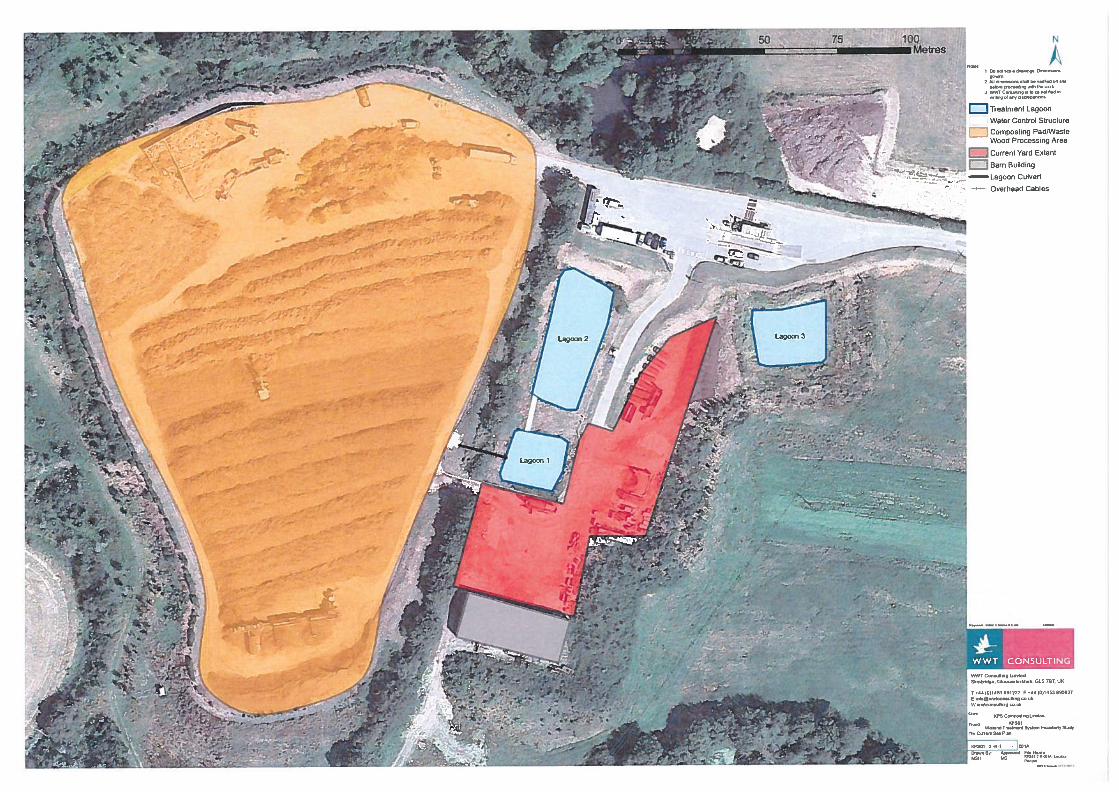
4.12 Lagoon 2 is the largest of the lagoons and is approximately 44 metres x 20 metres. As with Lagoon 1, the depth is between 4 and 6 metres. 6 – 8 aerator units are used within this lagoon to help maintain water quality. Sediment build up is rare in this lagoon with only occasional sediment removal required. Lagoon 2 features marginal vegetation around its edges and supports breeding Mallard Anas platyrhynchos and Moorhen Gallinula chloropus. Photograph 3, Appendix II, shows Lagoon 2.
4.13 Lagoon 3 is a large overflow lagoon and is not permanently connected to the first two lagoons. Located to the east of Lagoon 2 (see Figure 1, Appendix I), Lagoon 3 is 20 metres x 25 metres and has been created with a steep sided bund giving it an absolute maximum depth of 8-10 metres – however the typical operating water depth is somewhere between 1 and 4 metres. Common Frog Rana temporaria breed in the lagoon regularly and were observed in the pond during the site visit. Photograph 4, Appendix II, shows Lagoon 3.
4.14 At present water is retained in Lagoon 3 and is not discharged to a water course.
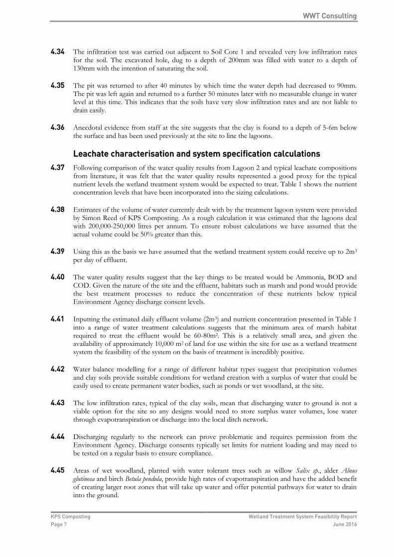
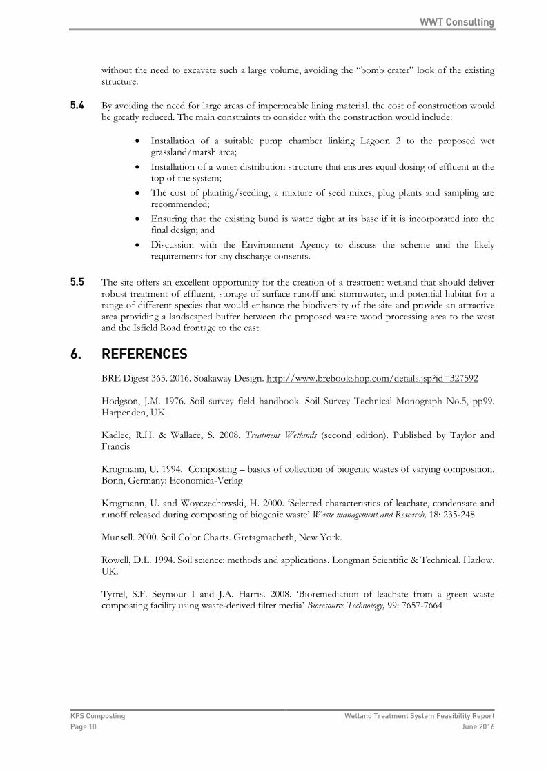
4.15 In addition to collecting the leachate and surface runoff from the main composting pad, the yard area adjacent to the lagoons (see Figure 1, Appendix I) is under drained by traditional grates and pipes that are connected to Lagoon 1. Oil interceptors are used in each of the collection points to capture oil from any of the large plant that are operated in this area. Photographs 5 and 6, Appendix II, show one of the collection points and typical operations for this area.
4.16 A large storage barn is located to the south of Lagoon 1. Rainwater from the roof of this barn is collected using gutter and discharged directly to the ditch network.
4.17 The current barn and yard area are due to be extended, a development that would see the removal of Lagoon 3 and an increase in the impermeable surfaces in this area. Figure 2, Appendix I, shows the approximate outline of the proposed extension. As part of the extension it is expected that rainwater harvesting would be used to collect roof water from the barn, which would be used for the cleaning of machinery and hard standing areas.
4.18 The area to the east of the yard is currently not in use and is the area earmarked for a wetland treatment system option that would replace Lagoon 3. The area had been used in the past as a dumping ground for compost waste and as such has high nutrient levels as indicated by the large area of nettles found adjacent to Lagoon 3. The area is crossed by electricity poles and wires which run approximately southeast – northwest along the line shown on Figure 1, Appendix 1. This would form an approximate boundary line marking the western edge of the area available for development which is shown in full on Figure 2, Appendix I.
4.19 Much of this area has been cleared recently ahead of the proposed developments and a large bund formed along the eastern and southern boundary. Temporary drainage channels have also been installed, one along the foot of the bund and another along the line of the electricity wires.
Hydrology 4.20 Following the assessment of the current treatment lagoons the walkover hydrological survey focused
on the proposed wetland treatment system and its surrounding area. The main focus was to identify connecting ditch networks and any water bodies that may be impacted by any changes to the site.
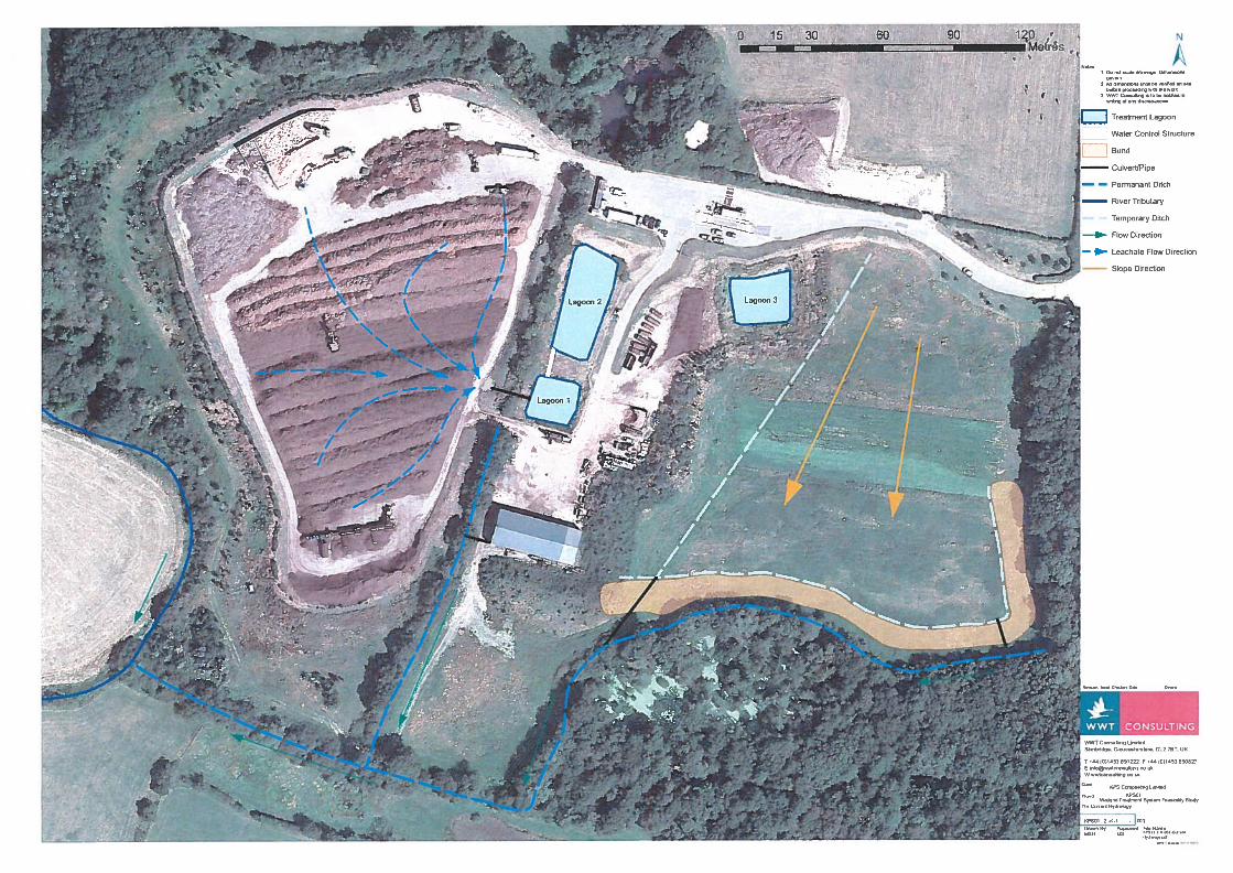
4.21 The proposed development area slopes gently from north to south. Surface water was present across the area suggesting low infiltration rates.
4.22 The proposed development area contains two temporary drainage ditches, one approximately follows the line of the telegraph poles/overhead cables and the other has been excavated at the foot of the bund that runs along the south of the field. On the day of the visit these two ditches

WWT Consulting
KPS Composting Wetland Treatment System Feasibility Report
Page 6 June 2016
contained some pools of water but were not running. Heavy rain earlier in the week meant that some surface water was present on the site but no flow of water was seen on the day.
4.23 The temporary ditches were installed to help drain water from the area, with water collecting at the base of the slope. Two culvert pipes were installed underneath the bund, one in the south eastern corner of the field and the other at the point where the two ditches connect. The first culvert discharges over ground and the other has a direct connection to the local ditch network.
4.24 Along the southern boundary of the field, behind the bund, is a drainage ditch that runs east to west, discharging into a wet woodland area with large ponds.
4.25 The ditch network was followed around the border of the site and edge of the woodland to the southern extreme of the KPS Composting Ltd land. Here the ditch straightens and runs approximately east-west until it joins the Iron River a tributary of the large River Ouse.
4.26 The land on the southern side of this ditch features a large pond and other wetland areas with marsh habitats and marginal vegetation observed from a distance.
4.27 An additional drainage ditch was observed running north-south from the western edge of the yard area down to the ditch network. This ditch is currently used to discharge roof water collected from the yard buildings.
4.28 Figure 3, Appendix I, shows the hydrological features identified on site.
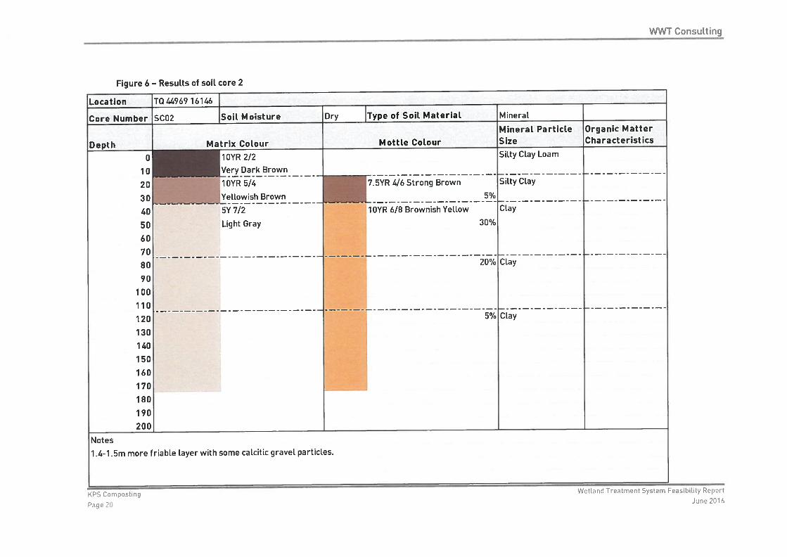
Soils and infiltration 4.29 Three soil cores were taken from the site from the potential development area. Due to the
uniformity of the soil cores it was not necessary to carry out further excavation. Figure 4, Appendix I, shows the location of the soil cores and Figures 5-7 detail the raw data collected in the field.
4.30 All three cores featured a top soil layer of silty clay loam for the first 20-30cm before clay became the dominant soil type. Mottling was present in all three cores suggesting that groundwater levels fluctuate regularly at the site and may be present shallowly below the surface.
4.31 Soil Core 1 and 2, taken from the southern end of the development were very similar. Following the initial dark brown silty clay loam layer both cores contained a second, lighter brown layer that had a higher clay content with strong brown mottle colours. In both cores this layer preceded very pale brown clay layers with a more yellow mottle colour. Mottle percentages ranged from 10-40% and in the case of Soil Core 1 the mottle colour became the background colour, suggesting regular saturation of this zone. The deeper areas of these cores were pale gray with increasing levels of mottling with depth. Both cores also had a narrow band that occurred between 120cm and 150cm that contained small pieces of gravel or grit that appeared to be calcitic. The texture of the clay also became more friable in this band further suggesting a slight calcitic influence.
4.32 Though the water table was not intercepted in any of the cores the soil at the base of Soil Core 1 was starting to feel wet and it is likely that had further excavation been possible that the water table would have been encountered within the next 20-50cm.
4.33 Soil Core 3 was similar in the upper layers with the initial top soil layer (silty clay loam) followed by a lighter layer with increased clay content. The colour of the deeper clay in this core was much greener than Soil Cores 1 and 2 and mottling was darker and less prevalent. Being upslope of Soil Cores 1 and 2 it is likely that groundwater does not rise in the upper parts of the field for as long as it does towards the base of the slope.
WWT Consulting
KPS Composting Wetland Treatment System Feasibility Report
Page 7 June 2016
4.34 The infiltration test was carried out adjacent to Soil Core 1 and revealed very low infiltration rates for the soil. The excavated hole, dug to a depth of 200mm was filled with water to a depth of 130mm with the intention of saturating the soil.
4.35 The pit was returned to after 40 minutes by which time the water depth had decreased to 90mm. The pit was left again and returned to a further 50 minutes later with no measurable change in water level at this time. This indicates that the soils have very slow infiltration rates and are not liable to drain easily.
4.36 Anecdotal evidence from staff at the site suggests that the clay is found to a depth of 5-6m below the surface and has been used previously at the site to line the lagoons.
Leachate characterisation and system specification calculations
4.37 Following comparison of the water quality results from Lagoon 2 and typical leachate compositions from literature, it was felt that the water quality results represented a good proxy for the typical nutrient levels the wetland treatment system would be expected to treat. Table 1 shows the nutrient concentration levels that have been incorporated into the sizing calculations.
4.38 Estimates of the volume of water currently dealt with by the treatment lagoon system were provided by Simon Reed of KPS Composting. As a rough calculation it was estimated that the lagoons deal with 200,000-250,000 litres per annum. To ensure robust calculations we have assumed that the actual volume could be 50% greater than this.
4.39 Using this as the basis we have assumed that the wetland treatment system could receive up to 2m3 per day of effluent.
4.40 The water quality results suggest that the key things to be treated would be Ammonia, BOD and COD. Given the nature of the site and the effluent, habitats such as marsh and pond would provide the best treatment processes to reduce the concentration of these nutrients below typical Environment Agency discharge consent levels.
4.41 Inputting the estimated daily effluent volume (2m3) and nutrient concentration presented in Table 1 into a range of water treatment calculations suggests that the minimum area of marsh habitat required to treat the effluent would be 60-80m2. This is a relatively small area, and given the availability of approximately 10,000 m2 of land for use within the site for use as a wetland treatment system the feasibility of the system on the basis of treatment is incredibly positive.
4.42 Water balance modelling for a range of different habitat types suggest that precipitation volumes and clay soils provide suitable conditions for wetland creation with a surplus of water that could be easily used to create permanent water bodies, such as ponds or wet woodland, at the site.
4.43 The low infiltration rates, typical of the clay soils, mean that discharging water to ground is not a viable option for the site so any designs would need to store surplus water volumes, lose water through evapotranspiration or discharge into the local ditch network.
4.44 Discharging regularly to the network can prove problematic and requires permission from the Environment Agency. Discharge consents typically set limits for nutrient loading and may need to be tested on a regular basis to ensure compliance.
4.45 Areas of wet woodland, planted with water tolerant trees such as willow Salix sp., alder Alnus glutinosa and birch Betula pendula, provide high rates of evapotranspiration and have the added benefit of creating larger root zones that will take up water and offer potential pathways for water to drain into the ground.

WWT Consulting
KPS Composting Wetland Treatment System Feasibility Report
Page 8 June 2016
4.46 Storm event modelling for a 1 in 100 year storm predicts that 96mm of rain could fall at the site during a 24 hour storm. Taking into account all of the impermeable surfaces at the site and the potential wetland treatment area and adding an additional 30% to allow for climate change, this could create 4,680m3 of water that would need to be stored or diverted off of site in some way or another.
Concept design
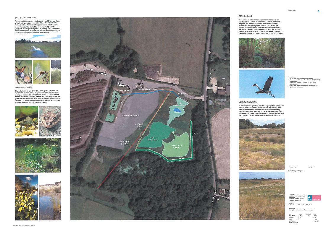
4.47 Taking into account the treatment of effluent, typical rainfall levels and stormwater storage a three stage wetland treatment system design would be recommended. Figure 8, Appendix I, shows a recommended layout for the system with the approximate areas of each treatment cell/habitat shown.
4.48 The treatment provided by Lagoons 1 and 2 removes a large amount of silt and sediment and also helps to neutralise the effluent, balancing the pH and diluting the effluent concentration. Effluent from Lagoon 2 would need to be pumped to the top of the system, thereafter the flow of water would be gravity dependant and no additional pumps should be required.
Stage 1 Wet grassland/marsh 4.49 The first stage of the system would be 200m2 of wet grassland/marsh. The effluent needs to be
distributed evenly along the margin of the wet grassland/marsh and allowed to flow over the surface. Shallow channels and depressions would allow water to be retained within the habitat allowing typical wet grassland and marginal vegetation to develop.
4.50 As the primary treatment cell the wet grassland and marsh would reduce nutrient levels in the effluent and remove any fine sediment that may still be in suspension. Areas of marsh offer oxygenised conditions that help reduce levels of Ammonia and other nutrients such as BOD and COD. Ammonia is broken down into Nitrate and Nitrite which can become diffused in water and taken up by plants and can also be volatised and released as initrogen gas into the atmosphere.
4.51 BOD and COD are reduced by the absorption and uptake of carbon by plants and microbes in standing water areas and are also released as carbon dioxide.
4.52 The area should be seeded with a wet grassland/meadow mix that would include a mixture of grasses such as Crested Dogstail Cynosurus cristatus, Common Bent Agrostis capillaris and Meadow Foxtail Alopecurus pratensis and wild flowers such as Yarrow Achillea millefolium, Meadowsweet Filipendula ulmaria and Common Sorrel Rumex acetosa
Stage 2 Pond/Open water 4.53 The wet grassland area would merge into an open water area with a pond of at least 50m2 in area.
Areas of open water offer conditions for a range of process that reduce levels of BOD, COD, Ammonia and other nutrients, acting in many of the same ways as the marsh above.
4.54 The pond would mimic natural ponds with shallowly sloping, vegetated margins and a range of water depths to encourage a variety of different marginal plants. Variable depth and vegetative cover also supports a range of invertebrates and amphibians and the pond would be likely to attract frogs and newts. Grassy margins would contain similar grass and flower species to the wet grassland area but wetter areas would also support wetland plant species such as Yellow Iris Iris pseudoacorus, Marsh Marigold Caltha palustris and Purple Loosestrife Lythrum salicaria. Given the presence of a number of other ponds and wetlands in the surrounding area it is recommended that local provenance wetland plant plugs and seed mixes are used to create an initial cover of plants that would then be enhanced by natural colonisation of wetland species from the surrounding wetlands.
4.55 Great Crested Newts have been found in the area and it is recommended that the pond includes some deeper areas that are favoured by this species.

WWT Consulting
KPS Composting Wetland Treatment System Feasibility Report
Page 9 June 2016
Stage 3 Wet Woodland 4.56 As a final stage it is recommended that 1,500m2 of mixed wet woodland is created. This would be
connected via a broad swale or channel and would receive water when the pond exceeds its normal working level.
4.57 The ground would be excavated to shallow depth with a variable topography that would encourage shallow pools of water to form suitable conditions for wet woodland to thrive.
4.58 Creating a large area of wet woodland would help with reduction of water surplus through storage and evapotranspiration. It also has the added benefit of creating similar habitat to that found on neighbouring land where an extensive area of established woodland supports a large heronry.
Stormwater storage and discharge points 4.59 The configuration suggested is robust enough to treat, store and recycle typical leachate and water
volumes generated by the site. However, it is prudent to include in the design, areas of long term storage for large storm events and discharge points for occasional exceedence discharge into the ditch network to prevent any flooding.
4.60 In the area adjacent to the suggested wet woodland, it is recommended that a long term storage area is created that is available to be flooded when required with a controlled discharge point controlling the flow of water.
4.61 This area could be a grass basin that is planted with species that are able to tolerate occasional inundation with stormwater.
4.62 The basin should be excavated to a shallow depth and bound by a bund, this could incorporate the existing, temporary bund but may need to be extended in some areas to ensure that flooding problems are not liable to be created elsewhere.
4.63 At present two discharge points have been placed underneath the bund and it is suggested that these could be used as emergency discharge points in the event of an extreme flood event. The existing pipes could be adapted to ensure that the flow of water is controlled to the typical Greenfield Runoff rate, replicating the drainage conditions were no changes made to the land use.
4.64 In addition, the current ditch that runs along the line of the telegraph wires could be retained and adapted to act as an additional overflow from the pond and wet woodland area.
5. CONCLUSIONS
5.1 The effluent generated by the compost facility receives a substantial amount of treatment from the existing lagoons and channels already utilised at the site. It is recommended that these are retained as the primary treatment process.
5.2 Installing a wetland treatment system at the site is highly feasible. The considerable area available for the wetland treatment area offers the opportunity to create a wetland treatment system that would have the look and feel of a more natural wetland site and can incorporate areas of grassland, woodland and permanent water bodies. By replicating natural habitats over installing a more engineered approach the wetland treatment system should be relatively cheap to install, with no major expense of materials and would also have the added benefit of requiring less frequent management.
5.3 The clay soils at the site appear ideal for use as a natural lining to the wetland areas. Already used as the lining on the lagoons, the area available for development clearly retains water well and with careful management can be designed in a way to easily replicate the storage capacity of Lagoon 3,
WWT Consulting
KPS Composting Wetland Treatment System Feasibility Report
Page 10 June 2016
without the need to excavate such a large volume, avoiding the “bomb crater” look of the existing structure.
5.4 By avoiding the need for large areas of impermeable lining material, the cost of construction would be greatly reduced. The main constraints to consider with the construction would include:
Installation of a suitable pump chamber linking Lagoon 2 to the proposed wet grassland/marsh area;
Installation of a water distribution structure that ensures equal dosing of effluent at the top of the system;
The cost of planting/seeding, a mixture of seed mixes, plug plants and sampling are recommended;
Ensuring that the existing bund is water tight at its base if it is incorporated into the final design; and
Discussion with the Environment Agency to discuss the scheme and the likely requirements for any discharge consents.
5.5 The site offers an excellent opportunity for the creation of a treatment wetland that should deliver robust treatment of effluent, storage of surface runoff and stormwater, and potential habitat for a range of different species that would enhance the biodiversity of the site and provide an attractive area providing a landscaped buffer between the proposed waste wood processing area to the west and the Isfield Road frontage to the east.
6. REFERENCES
BRE Digest 365. 2016. Soakaway Design. http://www.brebookshop.com/details.jsp?id=327592 Hodgson, J.M. 1976. Soil survey field handbook. Soil Survey Technical Monograph No.5, pp99. Harpenden, UK. Kadlec, R.H. & Wallace, S. 2008. Treatment Wetlands (second edition). Published by Taylor and Francis Krogmann, U. 1994. Composting – basics of collection of biogenic wastes of varying composition. Bonn, Germany: Economica-Verlag Krogmann, U. and Woyczechowski, H. 2000. ‘Selected characteristics of leachate, condensate and runoff released during composting of biogenic waste’ Waste management and Research, 18: 235-248 Munsell. 2000. Soil Color Charts. Gretagmacbeth, New York. Rowell, D.L. 1994. Soil science: methods and applications. Longman Scientific & Technical. Harlow. UK. Tyrrel, S.F. Seymour I and J.A. Harris. 2008. ‘Bioremediation of leachate from a green waste composting facility using waste-derived filter media’ Bioresource Technology, 99: 7657-7664
Client: KPS Composting
Project: Wetland Treatment System Feasibility Study
Date: June 2016
Report: Wetland Treatment System Feasibility Report
WWT Consulting
Wildfowl & Wetlands Trust (Consulting) Ltd accept no responsibility or liability for any use which is made of this document other than by the Client for the purpose for which it was originally commissioned and prepared. This
document solely represents the views of Wildfowl & Wetlands Trust (Consulting) Ltd.
All images in this report are copyright WWT or WWT Consulting unless otherwise stated and may not be reproduced without permission.
Created from Report Portrait WTS template V3 23/07/2013
Client: KPS Composting
Project: Wetland Treatment System Feasibility Study
Title: Wetland Treatment System
Feasibility Report
Issue:2
Date: June 2016
WWT Consulting
Wildfowl & Wetlands Trust Slimbridge, Gloucestershire GL2 7BT, UK
T +44 (0)1453 891222 F +44 (0)1453 890827
E [email protected] W wwtconsulting.co.uk
Checked by: GB
Approved by: MS

WWT Consulting
Contents
Contents
Figures
Tables
Photographs
1. INTRODUCTION
2. AIM AND OBJECTIVES
3. METHODS
Data review
Site visit
Leachate characterisation and system specification calculations
Concept development and design
4. RESULTS
Desk study
Site visit
Site description and existing leachate treatment
Hydrology
Soils and infiltration
Leachate characterisation and system specification calculations
Concept design
Stage 1 Wet grassland/marsh
Stage 2 Pond/Open water
Stage 3 Wet Woodland
Stormwater storage and discharge points
5. CONCLUSIONS
6. REFERENCES
APPENDIX I. FIGURES
APPENDIX II. PHOTOGRAPHS
Figures
Figure 1 – Site location plan showing current operational features
Figure 2 – Extension plan showing planned building and yard extension and the potential location of a revised wetland treatment system
Figure 3 – Hydrological map showing the current hydrological features and flow directions
Figure 4 – Map showing the location of soil cores taken during the site visit
Figure 5 – Results of soil core 1
Figure 6 – Results of soil core 2
Figure 7 – Results of soil core 3
Figure 8 – Concept design

WWT Consulting
Tables
Table 1 Results of effluent sampling carried out by KPS Compostnig
Photographs
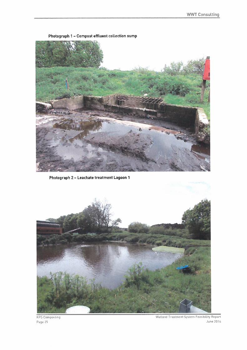
Photograph 1 – Compost effluent collection sump
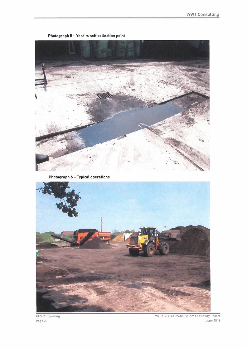
Photograph 2 – Leachate treatment Lagoon 1
Photograph 3 – Leachate treatment Lagoon 2
Photograph 4 – Leachate treatment Lagoon 3
Photograph 5 – Yard runoff collection point
Photograph 6 – Typical operations

WWT Consulting
KPS Composting Wetland Treatment System Feasibility Report
Page 1 June 2016
1. INTRODUCTION
1.1 Wildfowl and Wetlands Trust (Consulting) Ltd (WWT Consulting) have been contracted by KPS Composting Ltd (KPS Composting) to assess the feasibility of adapting their current compost leachate treatment lagoons to enhance the treatment of the wastewater and also create an attractive wetland area that would support a range of wetland plant and animal species and enhance the biodiversity of the site.
1.2 KPS Composting operates an open windrow green composting facility at Isfield, East Sussex, that receives green waste from commercial and domestic sources. The green waste is stored on a large concrete pad and recycled to create a range of soils, compost and bark for horticultural and agricultural uses. KPS Composting also undertakes waste wood processing at the site to produce wood chip for use in board manufacturing and also as a bio-fuel.
1.3 This report details the methods and results of the feasibility assessment.
2. AIMS AND OBJECTIVES
2.1 The aim of the project was to assess the feasibility of adapting the compost treatment lagoons into wetland areas to enhance treatment of site wastewater. This aim was achieved by completing the following objectives:
Undertake a short data review;
Undertake a site assessment;
Undertake detailed calculations to assess the suitability of the site; and
Produce an outline concept design of a working wetland solution.
3. METHODS
Data review
3.1 A short data review has been carried out to help characterise the likely chemistry and volume of the leachate effluent created by the composting facility and provide background information about the site.
3.2 A number of reports and other sources of information have been provided by the client and have included:
Water chemistry testing of the existing leachate;
Chemical testing of the compost;
Site plans and photographs; and
Ecological survey results from the neighbouring land.
3.3 Additional information regarding compost leachate has been sought through a short literature review to help provide context for the water chemistry results provided by the client and to further inform the leachate characterisation.
Site visit
3.4 A site visit was carried out on the 12th May 2016 to carry out walkover hydrology and soil surveys and to also experience the site first hand.
WWT Consulting
KPS Composting Wetland Treatment System Feasibility Report
Page 2 June 2016
3.5 An initial site walkover was carried out with Simon Reed and Daryl Walker of KPS Consulting to discuss the composting process and existing leachate collection method. This was also an ideal opportunity to discuss the future plans for the site (development and extension) and also opportunities and constraints that may help or hinder any additional development.
3.6 The hydrological survey involved a walkover survey to identify any surface hydrological features (streams, ponds, rivers etc.) and any other features that could impact on the hydrology of the site (culverts, pipes, water sources etc.). Key features were photographed and marked on an aerial photograph of the site for subsequent mapping.
3.7 Three soil cores were taken from the area proposed for the creation of wetland treatment systems/wetland creation. Soil cores were removed using a 50mm Dutch auger and each sample described to a depth of at least 150cm, using the method described in the Soil Survey Field Handbook (Hodgson, 1976). Six properties were recorded for every 10cm of the profile: soil material, matrix colour, mottle colour, texture, organic matter and soil moisture. All of these properties were determined in the field. Matrix colour and mottle colour were recorded by reference to a Munsell Soil Colour Chart (2000). Colours determined were recorded as colour descriptions. Texture and mineral material were determined using a finger assessment method for mineral soils outlined in Rowell (1994).
3.8 A shallow trial pit was also excavated on the site to assess the infiltration rates of the soils. This was done using a methodology that adapted the approach described in BRE Digest 365. A hole 100mm x 100mm x 200mm was excavated and half filled with water. The amount of time for water to drain from the hole was recorded and used to estimate the infiltration rate.
Leachate characterisation and system specification calculations
3.9 Using the results of the data review and also meteorological data an estimated chemical composition and annual volume of leachate was estimated for use in further sizing calculations. This has been estimated using information from site specific water chemistry tests and volume estimates, and has been contextualised with data from published reports relating to green composting chemistry.
3.10 The water chemistry has been used to estimate the type of treatment system that is best suited to the situation taking into account the removal of pollutants and nutrients, stormwater storage, the minimum capacity required whilst providing a cost effective but ecologically beneficial design.
3.11 To assess the area required to provide treatment, a number of different water treatment equations have been used that take into account a range of different factors, this includes the inflow of effluent, the concentration of particular nutrients or pollutants and the target effluent concentration. Equations used include the k-C* Model, Kickuth and Reed (Kadlec and Wallace 2009).
3.12 These models give us an indication of the likely performance of different wetland habitat types allowing selection of the best habitats for treatment taking into account the area available and the conditions presented at the site.
3.13 The second stage of sizing used 30 year average rainfall and temperature data taken from three weather stations local to the site to create a series of water balance models. These take into account average rainfall and estimate evapotranspiration rates to calculate the amount of water that would be lost through evaporation and infiltration and the surplus of water that would be available to create and support the various wetland habitats.
3.14 The final stage of the system specification was to consider storm rainfall events and the area/volume required to attenuate a large storm event. Modelled rainfall data was obtained from Flood Estimation Handbook Web Service (https://fehweb.ceh.ac.uk/), this provides modelled
WWT Consulting
KPS Composting Wetland Treatment System Feasibility Report
Page 3 June 2016
rainfall estimates for the site for a range of storm lengths and intensities. For these calculations a 1 in 100 year storm event for 24 hours was used as the worst case scenario.
Concept development and design
3.15 Following calculation a proposed layout for a treatment system has been produced. This is an indicative layout with approximate areas and recommended treatment wetland cell descriptions are included in the report.
4. RESULTS
Desk study
4.1 Leachate is free water draining from a compost heap that has been an integral part of the compost heap matrix for a sufficient time to solubilize organic and inorganic compounds. Leachate includes rainfall that percolates through the pile. Depending on the origin, quality, rate of decomposition and stability of the composting material, leachates can reach high concentrations of organic compounds (Biochemical Oxygen Demand (BOD) and Chemical Oxygen Demand (COD), nutrients, and salts.
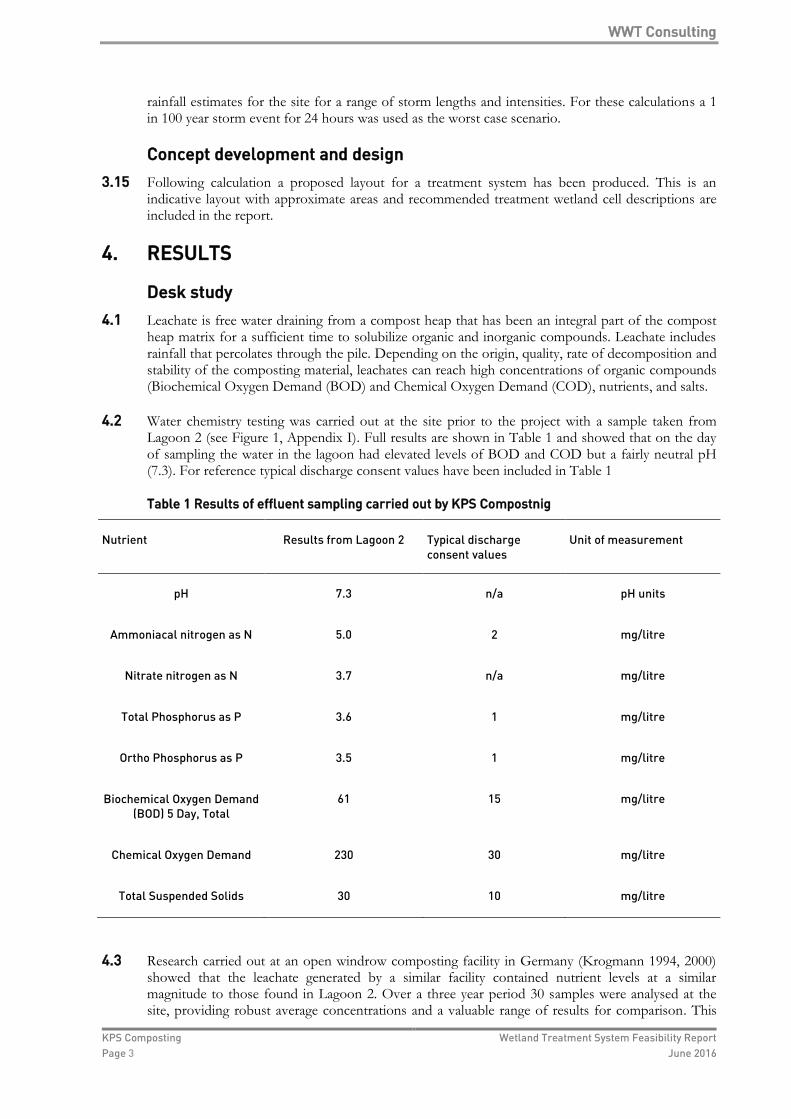
4.2 Water chemistry testing was carried out at the site prior to the project with a sample taken from Lagoon 2 (see Figure 1, Appendix I). Full results are shown in Table 1 and showed that on the day of sampling the water in the lagoon had elevated levels of BOD and COD but a fairly neutral pH (7.3). For reference typical discharge consent values have been included in Table 1
Table 1 Results of effluent sampling carried out by KPS Compostnig
Nutrient Results from Lagoon 2 Typical discharge consent values
Unit of measurement
pH 7.3 n/a pH units
Ammoniacal nitrogen as N 5.0 2 mg/litre
Nitrate nitrogen as N 3.7 n/a mg/litre
Total Phosphorus as P 3.6 1 mg/litre
Ortho Phosphorus as P 3.5 1 mg/litre
Biochemical Oxygen Demand (BOD) 5 Day, Total
61 15 mg/litre
Chemical Oxygen Demand 230 30 mg/litre
Total Suspended Solids 30 10 mg/litre
4.3 Research carried out at an open windrow composting facility in Germany (Krogmann 1994, 2000) showed that the leachate generated by a similar facility contained nutrient levels at a similar magnitude to those found in Lagoon 2. Over a three year period 30 samples were analysed at the site, providing robust average concentrations and a valuable range of results for comparison. This

WWT Consulting
KPS Composting Wetland Treatment System Feasibility Report
Page 4 June 2016
showed pH to vary between 6.62 and 8.47 and mean levels of ammoniacal nitrogen (NH4-N) at 8.4 mg/l, nitrate (NO3) at 7.1 mg/l, BOD at 19mg/l and COD at 266 mg/l.
4.4 The nature of the open windrow facilities means that the leachate is diluted a significant amount by rainwater from the composting area, traffic areas and the surfaces of the compost piles themselves.
4.5 In the UK, Tyrrel, Seymour and Harris (2008) carried out tests of bioremediation of leachate generated by a typical green waste composting facility. For this test, four batches of leachate were collected from Sita’s Lount composting facility and treated through a range of different biofilters. The composition of the leachate used in the tests had a higher average pH value of 8.685 than that recorded in Lagoon 2 or in the German example. Other nutrients and compounds were of a similar order of magnitude with mean levels of Ammoniacal nitrogen recorded at 20.315 mg/l, Nitrate and Nitrite at 0.49 mg/l, BOD at 124 mg/l and COD at 856 mg/l. It is worth nothing that the first sample used in this trial was described in the paper as “more dilute than expected”, it is not clear how the leachate used in this trial was collected. The “more dilute” sample was very similar to the sample collected from Lagoon 2.
4.6 As part of the planning application being submitted by KPS Composting, a Great Crested Newt Triturus cristatus survey has been carried out in the current leachate treatment lagoons and a number of water bodies on land that surround the site. While Great Crested Newts were not found within the lagoons, they have been found to be present in five different ponds between 100 and 500m from the composting facility. The closest is a small pond in land directly opposite the main entrance to the KPS Composting site and the other a larger pond to the south of the composting facility.
Site visit
Site description and existing leachate treatment 4.7 The KPS Composting facility is located on the edge of the village of Isfield, East Sussex (Grid
Reference TQ 44796 16209) and is an open windrow green waste composting facility. Large volumes of organic waste (horticultural and agricultural – grass cuttings, garden waste, wood chipping) are stored on site on a large concrete pad where they breakdown and are recycled as compost and soil improver.
4.8 Figure 1, Appendix I, shows an aerial photograph of the site with the main operational features labelled.
4.9 Leachate generated by the large piles of compostable material and any surface runoff from concrete areas on site are channelled and piped to a two stage treatment lagoon in the centre of the site. Leachate and surface water from the main concrete pad flows to a single concrete sump as shown on Figure 1. Water enters the sump through a row of 100mm diameter pipes with daily inspections carried out to ensure that the pipes have not become clogged or blocked by plant debris or sediment. A concrete catch pit flows out through a larger 600mm diameter twin wall pipe that connects through to the primary treatment lagoon. Photograph 1, Appendix II, shows the collection sump.
4.10 Lagoon 1 (see Figure 1, Appendix I) is approximately 18 metres x 16 metres in area and is estimated to be between 4 and 6 metres deep. This is the main sediment and solid material trap and requires regular de-silting – typically carried out every 1-2 years. 2 – 3 aerators are employed in the lagoon to help retain some oxygen in the water and enhance the breakdown of some of the nutrients within the leachate and surface runoff. Photograph 2, Appendix II, shows Lagoon 1.
4.11 Lagoon 1 is connected to a 2nd, larger lagoon (Lagoon 2) via a concrete channel approximately 12 metres x 2 metres and an estimated 2-3 metres deep. The channel contains a number of features to help capture sediment and solids with regular baffles along the length of channel and wire grates of decreasing size also used throughout the channel.