16
Zimmer ® Small Fragment Universal Locking System Surgical Technique
Zimmer® Small Fragment
Universal Locking System
Surgical Technique

Zimmer® Small Fragment Universal Locking System 1
Zimmer Small Fragment Universal Locking System Surgical Technique
Table of Contents
Introduction 2
Indications for Use 3
Plate Features 3
Locking Screw Features 4
Fixation Principles 5Standard Plating 5
Locked Plating 5
Combined Plating 5
Surgical Technique 6Required Instrumentation 6
Preoperative Preparation 6
Fracture Reduction 6
Plate Selection 6
Plate Positioning 6
Screw Insertion 7
Buttress Plate 7
Locking Screws 8
MIS Insertion Technique 9
Wound Closure 12
Postoperative Treatment 12
Implant Removal 12
Order Information 13
Zimmer® Small Fragment Universal Locking System2
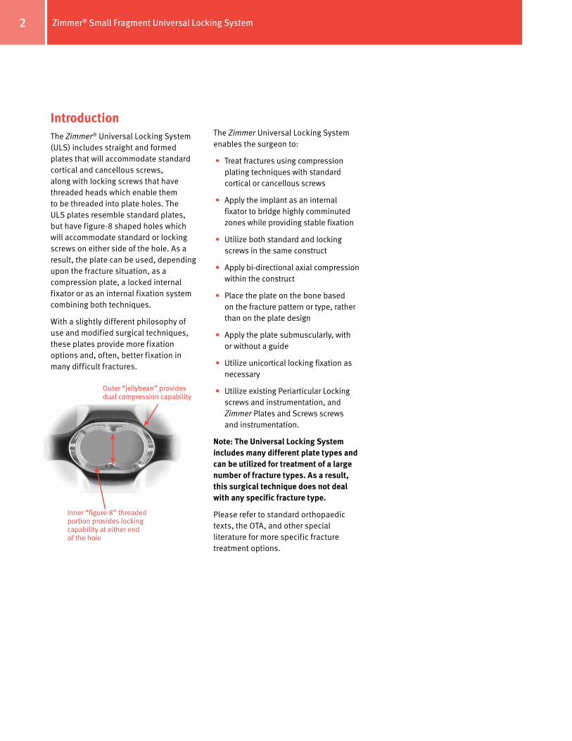
IntroductionThe Zimmer® Universal Locking System (ULS) includes straight and formed plates that will accommodate standard cortical and cancellous screws, along with locking screws that have threaded heads which enable them to be threaded into plate holes. The ULS plates resemble standard plates, but have figure-8 shaped holes which will accommodate standard or locking screws on either side of the hole. As a result, the plate can be used, depending upon the fracture situation, as a compression plate, a locked internal fixator or as an internal fixation system combining both techniques.
With a slightly different philosophy of use and modified surgical techniques, these plates provide more fixation options and, often, better fixation in many difficult fractures.
The Zimmer Universal Locking System enables the surgeon to:
• Treat fractures using compression plating techniques with standard cortical or cancellous screws
• Apply the implant as an internal fixator to bridge highly comminuted zones while providing stable fixation
• Utilize both standard and locking screws in the same construct
• Apply bi-directional axial compression within the construct
• Place the plate on the bone based on the fracture pattern or type, rather than on the plate design
• Apply the plate submuscularly, with or without a guide
• Utilize unicortical locking fixation as necessary
• Utilize existing Periarticular Locking screws and instrumentation, and Zimmer Plates and Screws screws and instrumentation.
Note: The Universal Locking System includes many different plate types and can be utilized for treatment of a large number of fracture types. As a result, this surgical technique does not deal with any specific fracture type.
Please refer to standard orthopaedic texts, the OTA, and other special literature for more specific fracture treatment options.
Inner “figure-8” threaded portion provides locking capability at either end of the hole
Outer “jellybean” provides dual compression capability
Zimmer® Small Fragment Universal Locking System 3
Indications for Use
The Universal Locking Plate System is indicated for temporary internal fixation and stabilization of osteotomies and fractures, including:
Comminuted fractures
Supracondylar fractures
Extra-articular fractures
Fractures in osteopenic bone
Nonunions
Malunions
The Zimmer 3.5mm Universal LockingSystem includes:
3.5mm Locking Dual Compression Plates
Locking One-Third Tubular Plates
3.5mm Locking Reconstruction Plates
3.5mm Locking T-Plates
3.5mm Oblique Locking T-Plates
3.5mm Locking Screws
3.5mm Cortical Screws
4.0mm Cancellous Screws
The Zimmer 2.7mm Universal Locking System includes:
2.7mm Locking Dual Compression Plates
Locking One-Quarter Tubular Plates
2.7mm Locking Reconstruction Plates
2.7mm Locking T-Plates
2.7mm Locking L-Plates
2.7mm Oblique Locking L-Plates
2.7mm Locking Screws
2.7mm Cortical Screws
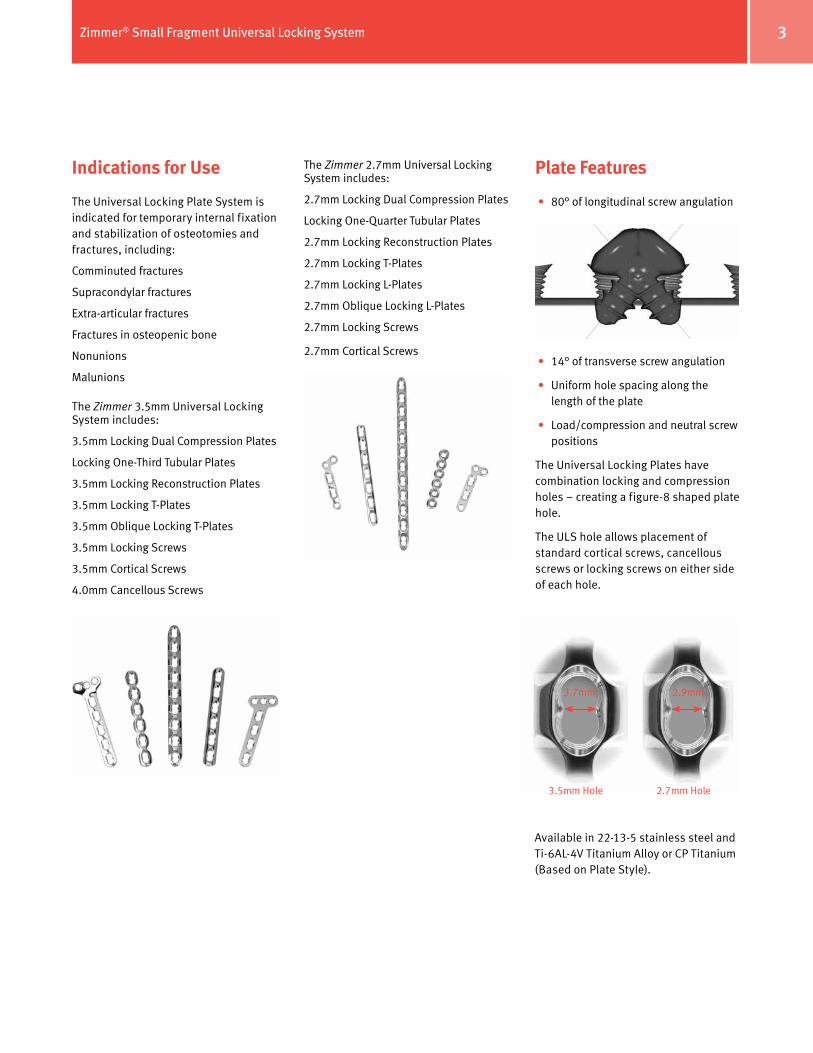
Plate Features
• 80° of longitudinal screw angulation
• 14° of transverse screw angulation
• Uniform hole spacing along the length of the plate
• Load/compression and neutral screw positions
The Universal Locking Plates have combination locking and compression holes – creating a figure-8 shaped plate hole.
The ULS hole allows placement of standard cortical screws, cancellous screws or locking screws on either side of each hole.
3.5mm Hole 2.7mm Hole
3.7mm 2.9mm
Available in 22-13-5 stainless steel and Ti-6AL-4V Titanium Alloy or CP Titanium (Based on Plate Style).
Zimmer® Small Fragment Universal Locking System4
Locking Screw Features
3.5mm Locking Screw
2.7mm Locking Screw
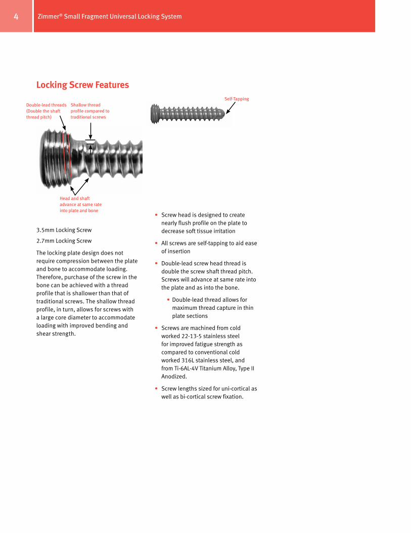
The locking plate design does not require compression between the plate and bone to accommodate loading. Therefore, purchase of the screw in the bone can be achieved with a thread profile that is shallower than that of traditional screws. The shallow thread profile, in turn, allows for screws with a large core diameter to accommodate loading with improved bending and shear strength.
• Screw head is designed to create nearly flush profile on the plate to decrease soft tissue irritation
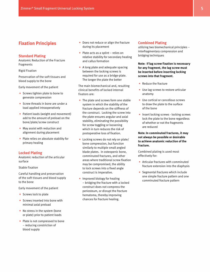
• All screws are self-tapping to aid ease of insertion
• Double-lead screw head thread is double the screw shaft thread pitch. Screws will advance at same rate into the plate and as into the bone.
• Double-lead thread allows for maximum thread capture in thin plate sections
• Screws are machined from cold worked 22-13-5 stainless steel for improved fatigue strength as compared to conventional cold worked 316L stainless steel, and from Ti-6AL-4V Titanium Alloy, Type II Anodized.
• Screw lengths sized for uni-cortical as well as bi-cortical screw fixation.
Double-lead threads (Double the shaft thread pitch)
Shallow thread profile compared to traditional screws
Head and shaft advance at same rate into plate and bone
Self-Tapping
Zimmer® Small Fragment Universal Locking System 5
• Does not reduce or align the fracture during its placement
• Plate acts as a splint – relies on relative stability for secondary healing and callus formation
• A long plate and adequate spacing between the locking screws is required for use as a bridge-plate. The longer the plate the better
The main biomechanical and, resulting clinical benefits of locked internal fixators are:
• The plate and screws form one stable system in which the stability of the fracture depends on the stiffness of the construct. Locking the screw into the plate ensures angular and axial stability, eliminating the possibility for screw toggling or loosening which in turn reduces the risk of postoperative loss of fixation.
• Locking screws do not rely on plate/bone compression, but function similarly to multiple small angled blade plates. In osteopenic bone, comminuted fractures, and other areas where traditional screw fixation may be compromised, the ability to lock screws into a fixed angle construct is imperative.
• Improved biology for healing – bridging the fracture with a locked construct does not compress the periosteum, or disrupt the fracture hematoma, thereby improving chances for fracture healing.
Combined Plating utilizing two biomechanical principles – interfragmentary compression and bridging techniques
Note: If lag screw fixation is necessary for any fragment, the lag screw must be inserted before inserting locking screws into that fragment.
• Reduce the fracture
• Use lag screws to restore articular anatomy
• Use cortical or cancellous screws to draw the plate to the surface of the bone
• Insert locking screws - locking screws lock the plate to the bone regardless of whether or not the fragments are reduced
Note: In comminuted fractures, it may not always be possible or desirable to achieve anatomic reduction of the fracture.
Combined plating is used most effectively for:
• Articular fractures with comminuted fracture extension into the diaphysis
• Segmental fractures which include one simple fracture pattern and one comminuted fracture pattern
Fixation Principles
Standard PlatingAnatomic Reduction of the Fracture Fragments
Rigid Fixation
Preservation of the soft tissues and blood supply to the bone
Early movement of the patient
• Screws tighten plate to bone to generate compression
• Screw threads in bone are under a load applied intraoperatively
• Patient loads (weight and movement) add to the amount of preload on the bone/plate/screw construct
• May assist with reduction and alignment during placement
• Plate relies on absolute stability for primary healing
Locked PlatingAnatomic reduction of the articular surface
Stable fixation
Careful handling and preservation of the soft tissues and blood supply to the bone
Early movement of the patient
• Screws lock to plate
• Screws inserted into bone with minimal axial preload
• No stress in the system (bone or plate) prior to patient loads
• Plate is not compressed to bone – reducing constriction of blood supply
Zimmer® Small Fragment Universal Locking System6
Surgical Technique
Required instrumentation
• 3.5mm Zimmer Universal Locking System Set or
• 2.7mm Zimmer Universal Locking System Set
In addition, the following sets may be used:
• 3.0mm Zimmer Cannulated Screw Set
• 3.5mm/4.0mm Zimmer Cannulated Screw Set
• Herbert™ or Herbert/Whipple® Screw Sets
Preoperative PreparationAfter assessing the fracture radiographically and preparing a preoperative plan, place the patient in the appropriate position on a radiolucent table. Be sure that the fluoroscope can be positioned to visualize the fracture in the both the lateral and anterior/posterior (A/P) views.
Fracture ReductionIt is imperative that accurate reduction of any articular fracture be obtained prior to and maintained during application of the Universal Locking plates.
Plate SelectionThe plates are available in a variety of lengths and sizes similar to the Zimmer Small Fragment System. If necessary, x-ray templates are available to help determine plate length and configuration.
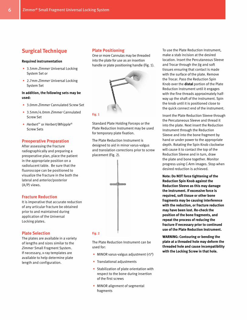
Plate PositioningOne or more Cannulas may be threaded into the plate for use as an insertion handle or plate positioning handle (Fig. 1).
Standard Plate Holding Forceps or the Plate Reduction Instrument may be used for temporary plate fixation.
The Plate Reduction Instrument is designed to aid in minor varus-valgus and translation corrections prior to screw placement (Fig. 2).
The Plate Reduction Instrument can be used for:
• MINOR varus-valgus adjustment (<5°)
• Translational adjustments
• Stabilization of plate orientation with respect to the bone during insertion of the first screws
• MINOR alignment of segmental fragments
To use the Plate Reduction Instrument, make a stab incision at the desired location. Insert the Percutaneous Sleeve and Trocar through the Jig and soft tissues ensuring that contact is made with the surface of the plate. Remove the Trocar. Pass the Reduction Spin Knob over the distal portion of the Plate Reduction Instrument until it engages with the fine threads approximately half-way up the shaft of the instrument. Spin the knob until it is positioned close to the quick connect end of the instrument.
Insert the Plate Reduction Sleeve through the Percutaneous Sleeve and thread it into the plate. Next insert the Reduction Instrument through the Reduction Sleeve and into the bone fragment by hand or under power to the appropriate depth. Rotating the Spin Knob clockwise will cause it to contact the top of the Reduction Sleeve and in turn, draw the plate and bone together. Monitor progress using C-Arm images. Stop when desired reduction is achieved.
Note: Do NOT force tightening of the Reduction Spin Knob against the Reduction Sleeve as this may damage the instrument. If excessive force is required, soft tissue or other bone fragments may be causing interference with the reduction, or fracture reduction may have been lost. Re-check the position of the bone fragments, and repeat the process of reducing the fracture if necessary prior to continued use of the Plate Reduction Instrument.
WARNING: Contouring or bending the plate at a threaded hole may deform the threaded hole and cause incompatibility with the Locking Screw in that hole.
Fig. 1
Fig. 2
Zimmer® Small Fragment Universal Locking System 7
Screw InsertionDetermine whether standard Cortical, Cancellous, or Locking Screws will be used. Any combination of screws may be used.
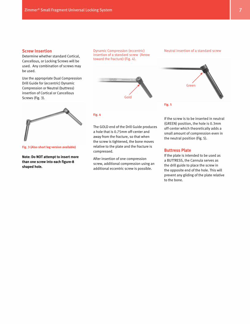
Use the appropriate Dual Compression Drill Guide for (eccentric) Dynamic Compression or Neutral (buttress) insertion of Cortical or Cancellous Screws (Fig. 3).
Note: Do NOT attempt to insert more than one screw into each figure-8 shaped hole.
Neutral insertion of a standard screw
If the screw is to be inserted in neutral (GREEN) position, the hole is 0.3mm off-center which theoretically adds a small amount of compression even in the neutral position (Fig. 5).
Buttress PlateIf the plate is intended to be used as a BUTTRESS, the Cannula serves as the drill guide to place the screw in the opposite end of the hole. This will prevent any gliding of the plate relative to the bone.
Fig. 3 (Also short leg version available)
Fig. 4
Fig. 5
Gold
Green
Dynamic Compression (eccentric) insertion of a standard screw (Arrow toward the fracture) (Fig. 4).
The GOLD end of the Drill Guide produces a hole that is 0.75mm off-center and away from the fracture, so that when the screw is tightened, the bone moves relative to the plate and the fracture is compressed.
After insertion of one compression screw, additional compression using an additional eccentric screw is possible.
Zimmer® Small Fragment Universal Locking System8
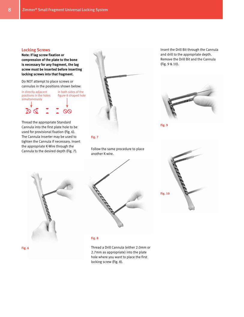
Locking ScrewsNote: If lag screw fixation or compression of the plate to the bone is necessary for any fragment, the lag screw must be inserted before inserting locking screws into that fragment.
Do NOT attempt to place screws or cannulas in the positions shown below:
Thread the appropriate Standard Cannula into the first plate hole to be used for provisional fixation (Fig. 6). The Cannula Inserter may be used to tighten the Cannula if necessary. Insert the appropriate K-Wire through the Cannula to the desired depth (Fig. 7).
in directly adjacent positions in the holes simultaneously
in both sides of the figure-8 shaped hole
Fig. 6
Fig. 7
Follow the same procedure to place another K-wire.
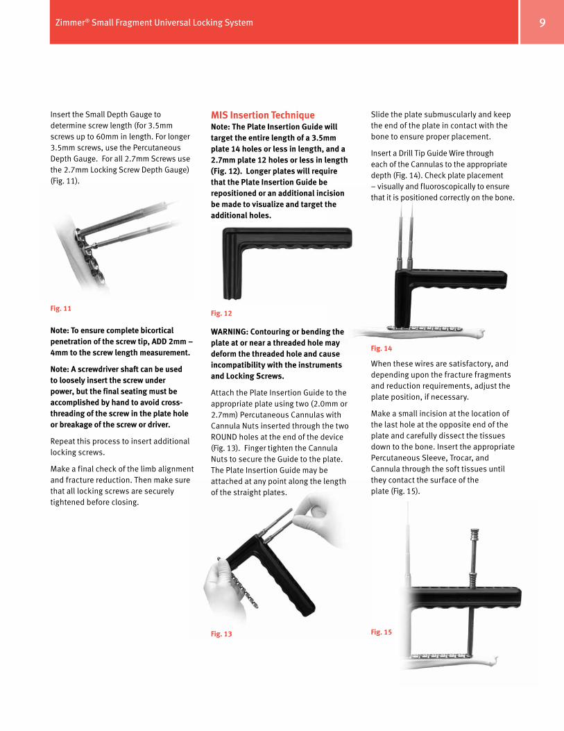
Thread a Drill Cannula (either 2.0mm or 2.7mm as appropriate) into the plate hole where you want to place the first locking screw (Fig. 8).
Fig. 8
Fig. 9
Fig. 10
Insert the Drill Bit through the Cannula and drill to the appropriate depth. Remove the Drill Bit and the Cannula (Fig. 9 & 10).
Zimmer® Small Fragment Universal Locking System 9
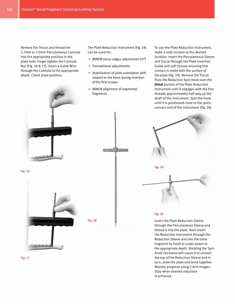
Insert the Small Depth Gauge to determine screw length (for 3.5mm screws up to 60mm in length. For longer 3.5mm screws, use the Percutaneous Depth Gauge. For all 2.7mm Screws use the 2.7mm Locking Screw Depth Gauge) (Fig. 11).
Note: To ensure complete bicortical penetration of the screw tip, ADD 2mm – 4mm to the screw length measurement.
Note: A screwdriver shaft can be used to loosely insert the screw under power, but the final seating must be accomplished by hand to avoid cross-threading of the screw in the plate hole or breakage of the screw or driver.
Repeat this process to insert additional locking screws.
Make a final check of the limb alignment and fracture reduction. Then make sure that all locking screws are securely tightened before closing.
Fig. 11
MIS Insertion TechniqueNote: The Plate Insertion Guide will target the entire length of a 3.5mm plate 14 holes or less in length, and a 2.7mm plate 12 holes or less in length (Fig. 12). Longer plates will require that the Plate Insertion Guide be repositioned or an additional incision be made to visualize and target the additional holes.
WARNING: Contouring or bending the plate at or near a threaded hole may deform the threaded hole and cause incompatibility with the instruments and Locking Screws.
Attach the Plate Insertion Guide to the appropriate plate using two (2.0mm or 2.7mm) Percutaneous Cannulas with Cannula Nuts inserted through the two ROUND holes at the end of the device (Fig. 13). Finger tighten the Cannula Nuts to secure the Guide to the plate. The Plate Insertion Guide may be attached at any point along the length of the straight plates.
Fig. 12
Fig. 13
Slide the plate submuscularly and keep the end of the plate in contact with the bone to ensure proper placement.
Insert a Drill Tip Guide Wire through each of the Cannulas to the appropriate depth (Fig. 14). Check plate placement – visually and fluoroscopically to ensure that it is positioned correctly on the bone.
When these wires are satisfactory, and depending upon the fracture fragments and reduction requirements, adjust the plate position, if necessary.
Make a small incision at the location of the last hole at the opposite end of the plate and carefully dissect the tissues down to the bone. Insert the appropriate Percutaneous Sleeve, Trocar, and Cannula through the soft tissues until they contact the surface of the plate (Fig. 15).
Fig. 14
Fig. 15
Zimmer® Small Fragment Universal Locking System10
Remove the Trocar and thread the 2.7mm or 2.0mm Percutaneous Cannula into the appropriate position in the plate hole. Finger tighten the Cannula Nut (Fig. 16 & 17). Insert a Guide Wire through the Cannula to the appropriate depth. Check plate position.
The Plate Reduction Instrument (Fig. 18) can be used for:
• MINOR varus-valgus adjustment (<5°)
• Translational adjustments
• Stabilization of plate orientation with respect to the bone during insertion of the first screws
• MINOR alignment of segmental fragments
Fig. 16
Fig. 17
Fig. 18
To use the Plate Reduction Instrument, make a stab incision at the desired location. Insert the Percutaneous Sleeve and Trocar through the Plate Insertion Guide and soft tissues ensuring that contact is made with the surface of the plate (Fig. 19). Remove the Trocar. Pass the Reduction Spin Knob over the distal portion of the Plate Reduction Instrument until it engages with the fine threads approximately half-way up the shaft of the instrument. Spin the knob until it is positioned close to the quick connect end of the instrument (Fig. 20).
Fig. 19
Fig. 20
Insert the Plate Reduction Sleeve through the Percutaneous Sleeve and thread it into the plate. Next insert the Reduction Instrument through the Reduction Sleeve and into the bone fragment by hand or under power to the appropriate depth. Rotating the Spin Knob clockwise will cause it to contact the top of the Reduction Sleeve and in turn, draw the plate and bone together. Monitor progress using C-Arm images. Stop when desired reduction is achieved.
Zimmer® Small Fragment Universal Locking System 11
Note: Do NOT force tightening of the Reduction Spin Knob against the Reduction Sleeve as this may damage the instrument. If excessive force is required, soft tissue or other bone fragments may be causing interference with the reduction, or fracture reduction may have been lost. Re-check the position of the bone fragments, and repeat the process of reducing the fracture if necessary prior to continued use of the Plate Reduction Instrument.
Remove the first Guide Wire.
Cortical ScrewsTo insert a Cortical Screw, use the appropriate Percutaneous Drill Bit and drill to the appropriate depth. Remove the Drill Bit, loosen the Cannula Nut, and remove the Cannula. Use the appropriate Percutaneous Depth Gauge to measure for screw length.
Note: The Depth Gauges are used to measure both Cortical and Locking Screw lengths.
Tapping is not typically necessary as the flutes of the screws are self-tapping, but if the bone is dense, the near cortex may be tapped using the 3.5mm Percutaneous ZPS Screw Tap.
Insert the appropriate Cortical screw using the 2.5mm Hex Percutaneous Screwdriver Bit under power.
Repeat this procedure to insert additional Cortical Screws.
Note: Secure the PLATE INSERTION GUIDE to the PLATE in at least two locations, one proximally and one distally using Percutaneous Sleeves, Cannulas and Cannula Nuts to maintain the position of the PLATE INSERTION GUIDE relative to the PLATE. DO NOT remove these until fixation is stable and nearly complete. Removal of the proximal and distal Cannulas and Cannula Nuts will cause the Plate Insertion Guide to shift, and may result in the inability to thread additional Cannulas into the plate holes.
Fig. 21
Note: To ensure complete bicortical penetration of the screw tip, ADD 2mm – 4mm to the screw length measurement.
Repeat this procedure to insert additional locking screws.
Tapping is not typically necessary as the flutes of the screws are self-tapping, but if the bone is dense, the near cortex may be tapped using the 3.5mm or 2.7mm Percutaneous Locking Screw Tap.
BE SURE THAT ALL LOCKING SCREWS ARE SECURELY TIGHTENED.
Make a final check of the limb alignment and fracture reduction. Then make sure that ALL LOCKING SCREWS ARE SECURLY TIGHTENED by hand before closing.
Loosen all remaining Cannula Nuts and remove the Sleeves, Cannulas, and the Plate Insertion Guide.
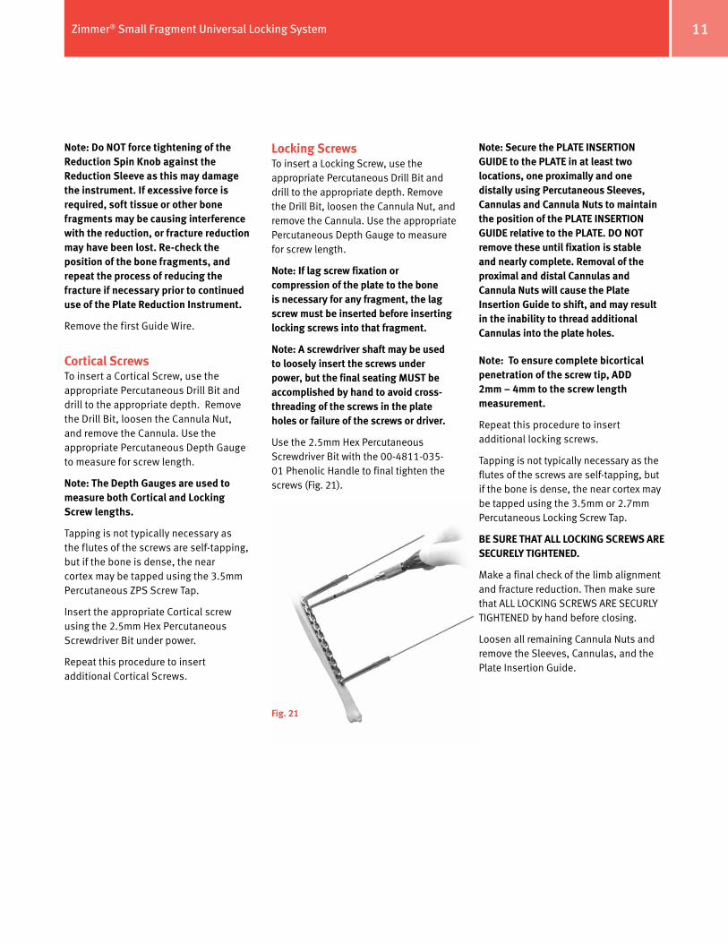
Locking ScrewsTo insert a Locking Screw, use the appropriate Percutaneous Drill Bit and drill to the appropriate depth. Remove the Drill Bit, loosen the Cannula Nut, and remove the Cannula. Use the appropriate Percutaneous Depth Gauge to measure for screw length.
Note: If lag screw fixation or compression of the plate to the bone is necessary for any fragment, the lag screw must be inserted before inserting locking screws into that fragment.
Note: A screwdriver shaft may be used to loosely insert the screws under power, but the final seating MUST be accomplished by hand to avoid cross-threading of the screws in the plate holes or failure of the screws or driver.
Use the 2.5mm Hex Percutaneous Screwdriver Bit with the 00-4811-035-01 Phenolic Handle to final tighten the screws (Fig. 21).
Zimmer® Small Fragment Universal Locking System12
Wound ClosureUse the appropriate method for surgical closure of the incisions.
Postoperative TreatmentPostoperative treatment with Universal Locking Plates does not differ from conventional internal fixation procedures.
Implant RemovalTo remove locking screws, unlock all screws from the plate and then remove the screws completely.


Contact your Zimmer representative or visit us at www.zimmer.com
Please refer to package insert for complete product information, including contraindications, warnings, precautions, and adverse effects.
97-4936-002-00 Rev. 3 1004-T21 3ML Printed in USA ©2006, 2009, 2010 Zimmer, Inc.
The CE mark is valid only if it is also printed on the product label.
+H124974936002001/$100518R3E10U


