66
MEASURING HORIZONTAL DISTANCES August 2014 Semester EGC1164 & EGC2164
MEASURING
HORIZONTAL DISTANCES
August 2014 Semester
EGC1164 & EGC2164
OUTLINE
• -1 Rough Distance Measurement – Determining a Unit Pace
– Using a Measuring Wheel
• -2 Taping: Equipment and Methods – Tapes and Accessories
– Taping a Horizontal Distance
– Setting Marks for Line and Distance
• -3 Taping Mistakes, Errors, and Corrections – Taping Mistakes or
Blunders
– Taping Errors
– Correction of Systematic Errors
• -4 Electronic Distance Measurement – Types of EDMIs
– EDMI Operating Procedure
5 Taping Corrections
Common Methods for Measuring
Distances
• One of the fundamentals of surveying is the need to measure
distance. Distances are not necessarily linear, especially if they
occur on the spherical earth. In the present subject we will deal
with distances in Euclidean (geometric) space, which we can
consider a straight line from one point or feature to another.
-Pacing
-Taping
-Tachometry (required theodolite, and graduated rod)
- EDM (Electronic Distance Measurement)
ROUGH DISTANCE
MEASUREMENT
• In certain surveying applications, only a
rough approximation of distance is
necessary; a method called pacing, or
the use of a simple measuring wheel,
may be sufficient in these instances.
• Distances can be measured with an
accuracy of about 1:100 by pacing.
– Distance = unit pace * number of paces
ROUGH DISTANCE
MEASUREMENT
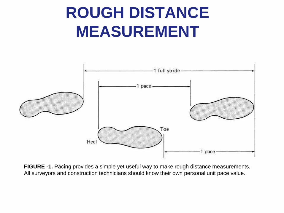
FIGURE -1. Pacing provides a simple yet useful way to make rough distance measurements.
All surveyors and construction technicians should know their own personal unit pace value.
ROUGH DISTANCE
MEASUREMENT
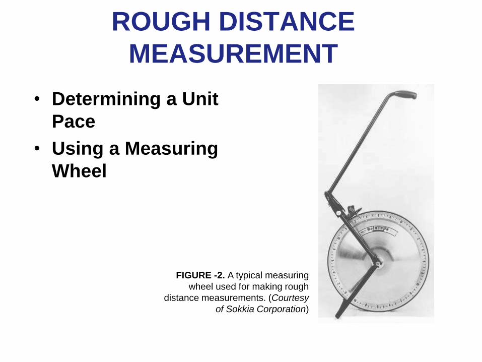
• Determining a Unit
Pace
• Using a Measuring
Wheel
FIGURE -2. A typical measuring
wheel used for making rough
distance measurements. (Courtesy
of Sokkia Corporation)
TAPING: EQUIPMENT AND
METHODS
• Measuring horizontal distances with a tape is
simple in theory, but in actual practice it is not
as easy as it appears at first glance.
– It requires skill and experience for a surveyor to
be able to tape a distance with a relative accuracy
between 1:3000 and 1:5000, which is a generally
accepted range for most preliminary surveys,
ordinary property surveys, and many types of
construction layouts.
TAPING: EQUIPMENT AND
METHODS
• Tapes and Accessories
– Steel Tapes
– Cut Tapes
– Add Tapes
– Invar and Lovar Tapes
– Accessories for Taping
– Precautions to Avoid Damaging the
Tape
9
Methods of Measurement
• Pacing
– Accuracy 1 : 100
• Taping
– Accuracy 1 : 10,000
• Electronic Distance Measurement (EDM)
– Accuracy 1 : 10,000 to 1:100,000
10
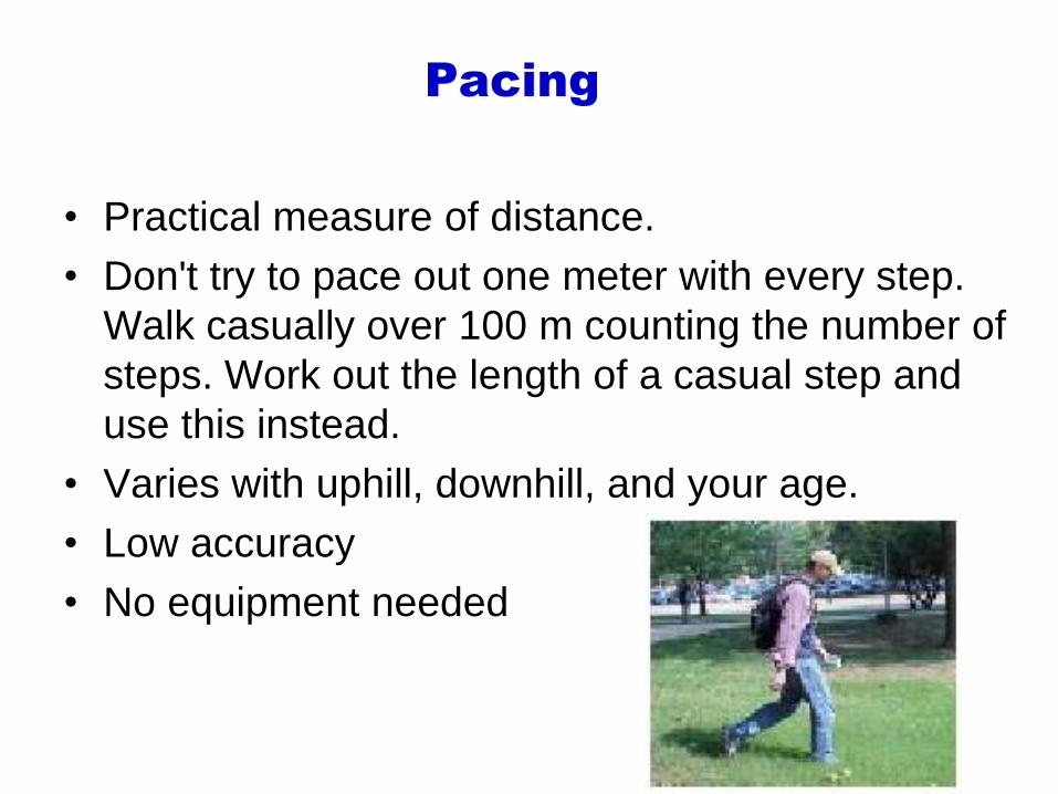
Pacing
• Practical measure of distance.
• Don't try to pace out one meter with every step.
Walk casually over 100 m counting the number of
steps. Work out the length of a casual step and
use this instead.
• Varies with uphill, downhill, and your age.
• Low accuracy
• No equipment needed
11
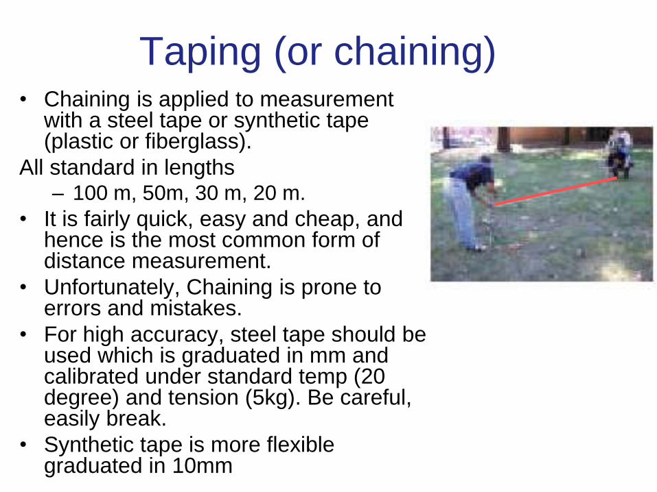
Taping (or chaining) • Chaining is applied to measurement
with a steel tape or synthetic tape (plastic or fiberglass).
All standard in lengths – 100 m, 50m, 30 m, 20 m.
• It is fairly quick, easy and cheap, and hence is the most common form of distance measurement.
• Unfortunately, Chaining is prone to errors and mistakes.
• For high accuracy, steel tape should be used which is graduated in mm and calibrated under standard temp (20 degree) and tension (5kg). Be careful, easily break.
• Synthetic tape is more flexible graduated in 10mm
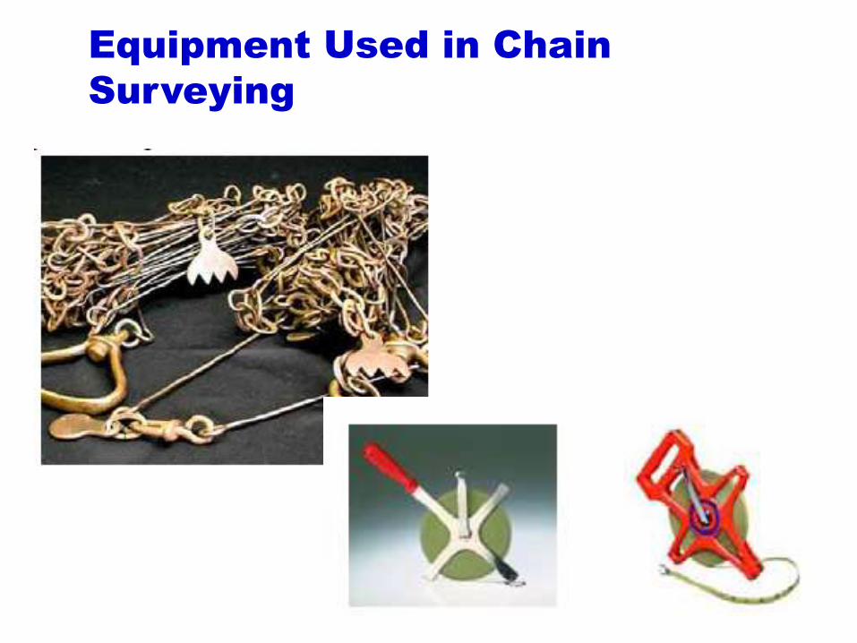
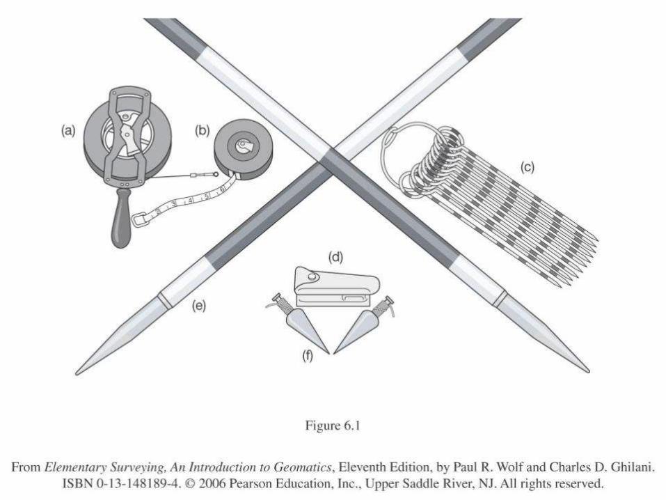
Equipment Used in Chain
Surveying
14
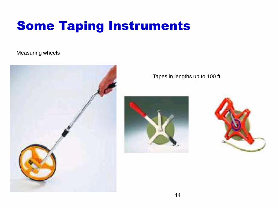
Measuring wheels
Tapes in lengths up to 100 ft
Some Taping Instruments
15
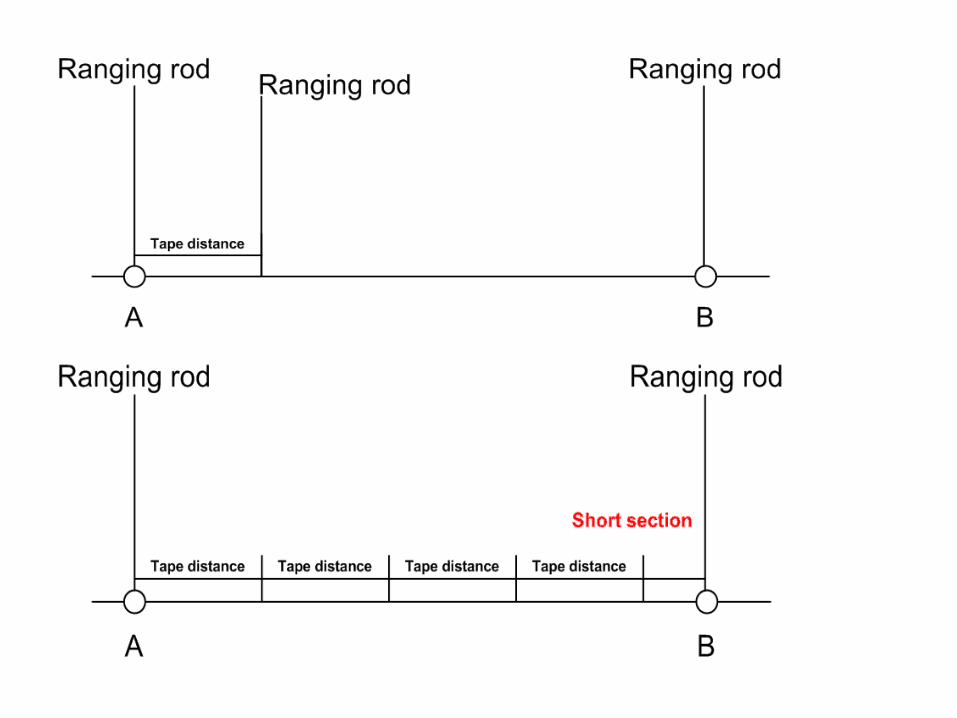
Taping Procedures
• Ranging rods set up between points A and B
from A to B, set zero of tape at A
• tape unwound towards B
• A third range rod is “ranged” in at C
• Tape straightened, held tight and read at rod C
• C marked with a pin
• for next bay, tape moved from A and zero set at C and so on
TAPING: EQUIPMENT AND
METHODS
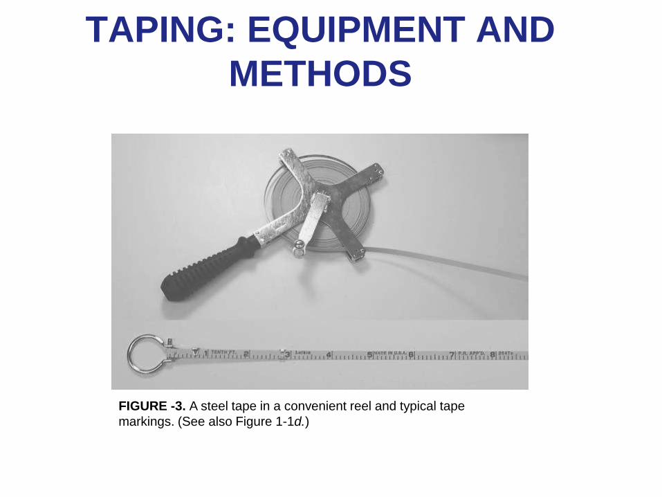
FIGURE -3. A steel tape in a convenient reel and typical tape
markings. (See also Figure 1-1d.)
TAPING: EQUIPMENT AND
METHODS
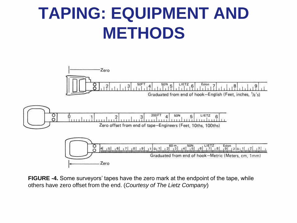
FIGURE -4. Some surveyors’ tapes have the zero mark at the endpoint of the tape, while
others have zero offset from the end. (Courtesy of The Lietz Company)
TAPING: EQUIPMENT AND
METHODS
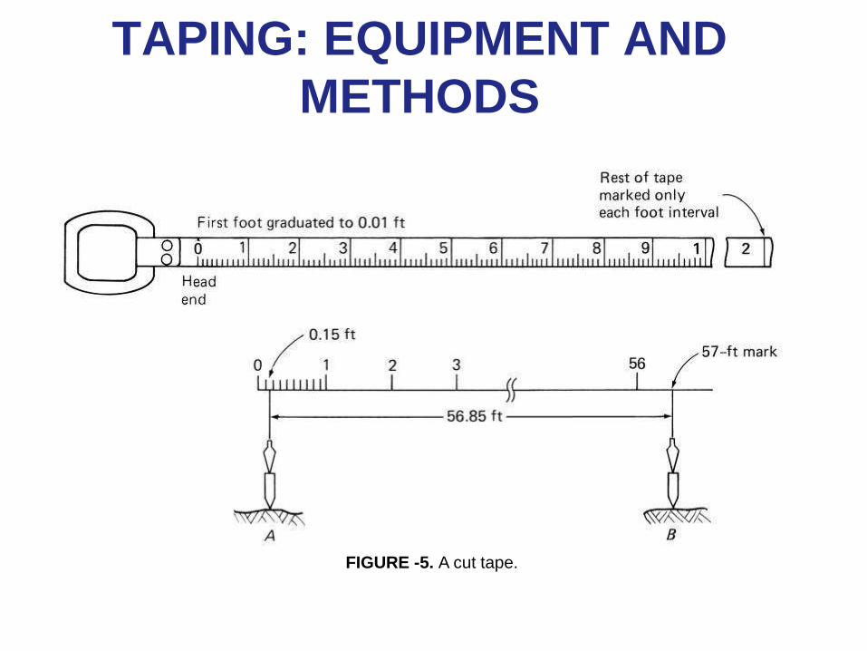
FIGURE -5. A cut tape.
TAPING: EQUIPMENT AND
METHODS
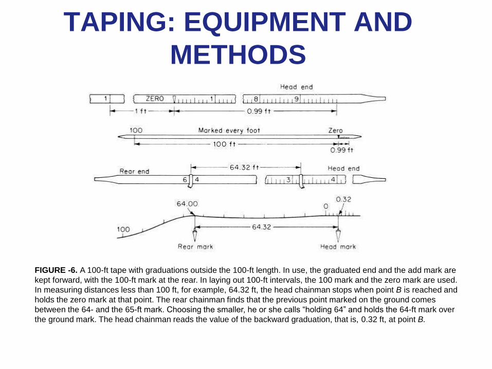
FIGURE -6. A 100-ft tape with graduations outside the 100-ft length. In use, the graduated end and the add mark are
kept forward, with the 100-ft mark at the rear. In laying out 100-ft intervals, the 100 mark and the zero mark are used.
In measuring distances less than 100 ft, for example, 64.32 ft, the head chainman stops when point B is reached and
holds the zero mark at that point. The rear chainman finds that the previous point marked on the ground comes
between the 64- and the 65-ft mark. Choosing the smaller, he or she calls “holding 64” and holds the 64-ft mark over
the ground mark. The head chainman reads the value of the backward graduation, that is, 0.32 ft, at point B.
TAPING: EQUIPMENT AND
METHODS
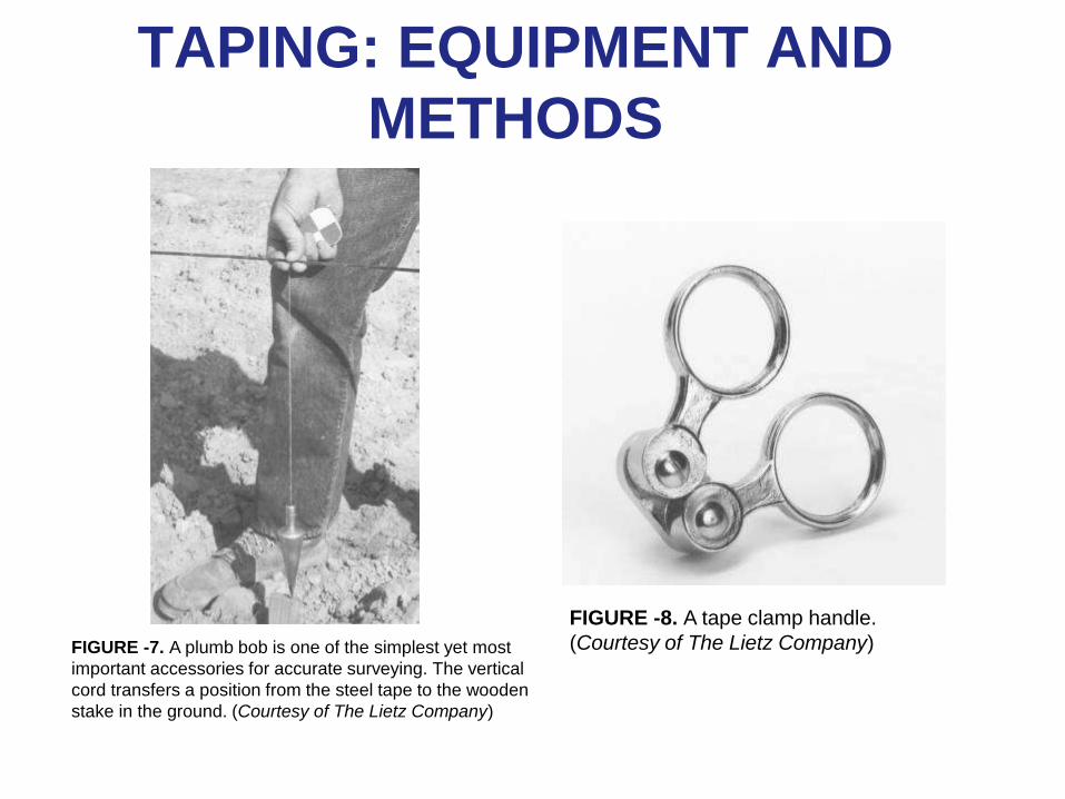
FIGURE -7. A plumb bob is one of the simplest yet most
important accessories for accurate surveying. The vertical
cord transfers a position from the steel tape to the wooden
stake in the ground. (Courtesy of The Lietz Company)
FIGURE -8. A tape clamp handle.
(Courtesy of The Lietz Company)
TAPING: EQUIPMENT AND
METHODS
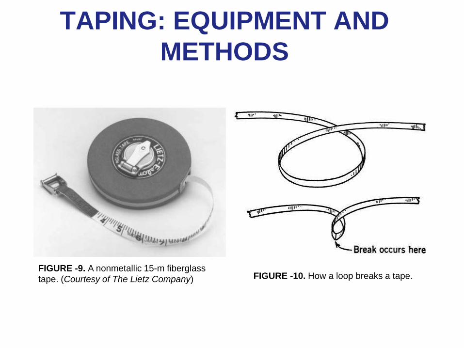
FIGURE -9. A nonmetallic 15-m fiberglass
tape. (Courtesy of The Lietz Company) FIGURE -10. How a loop breaks a tape.
TAPING: EQUIPMENT AND
METHODS
• Taping a Horizontal Distance
– Setting Out and Aligning the Tape
– Marking an Intermediate Station on Line
– Completing the Measurement
– Breaking Tape
TAPING: EQUIPMENT AND
METHODS
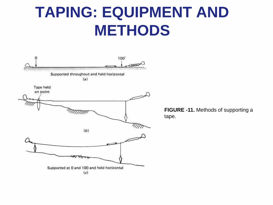
FIGURE -11. Methods of supporting a
tape.
TAPING: EQUIPMENT AND
METHODS
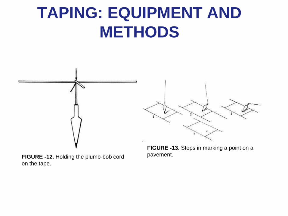
FIGURE -12. Holding the plumb-bob cord
on the tape.
FIGURE -13. Steps in marking a point on a
pavement.
TAPING: EQUIPMENT AND
METHODS
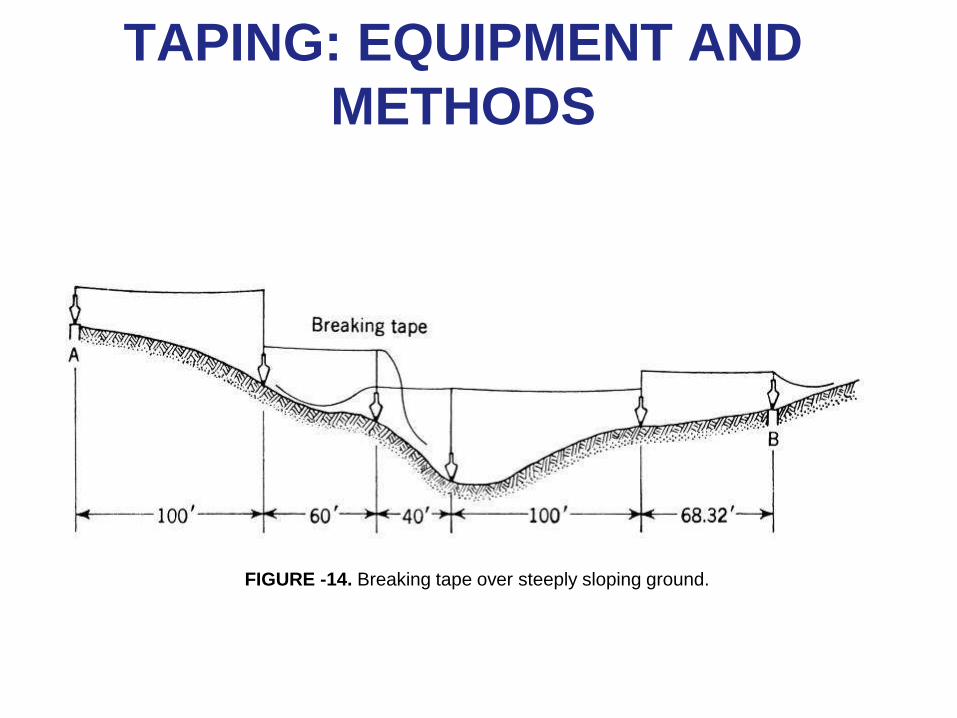
FIGURE -14. Breaking tape over steeply sloping ground.
TAPING: EQUIPMENT AND
METHODS
• Setting Marks for Line and Distance
– Identifying Stations
– Field Procedure
• Driving a Stake
• Setting a Tack
• Making Marks on Other Surfaces
TAPING: EQUIPMENT AND
METHODS
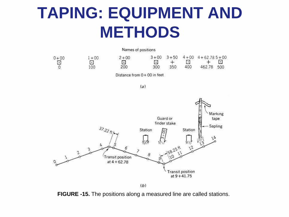
FIGURE -15. The positions along a measured line are called stations.
TAPING: EQUIPMENT AND
METHODS
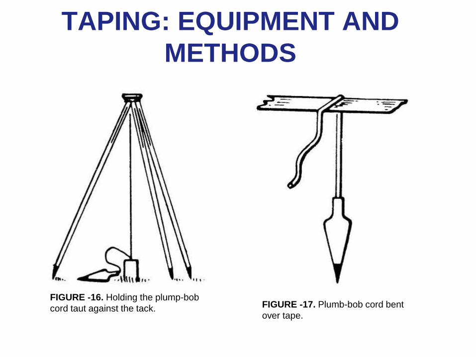
FIGURE -16. Holding the plump-bob
cord taut against the tack. FIGURE -17. Plumb-bob cord bent
over tape.
TAPING: EQUIPMENT AND
METHODS
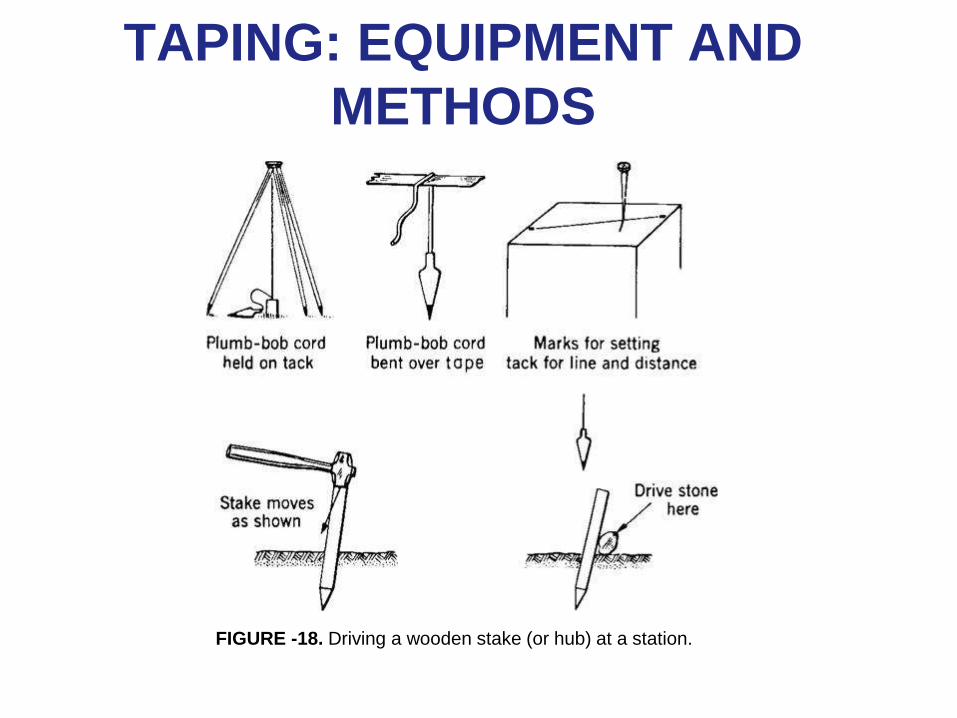
FIGURE -18. Driving a wooden stake (or hub) at a station.
TAPING: EQUIPMENT AND
METHODS
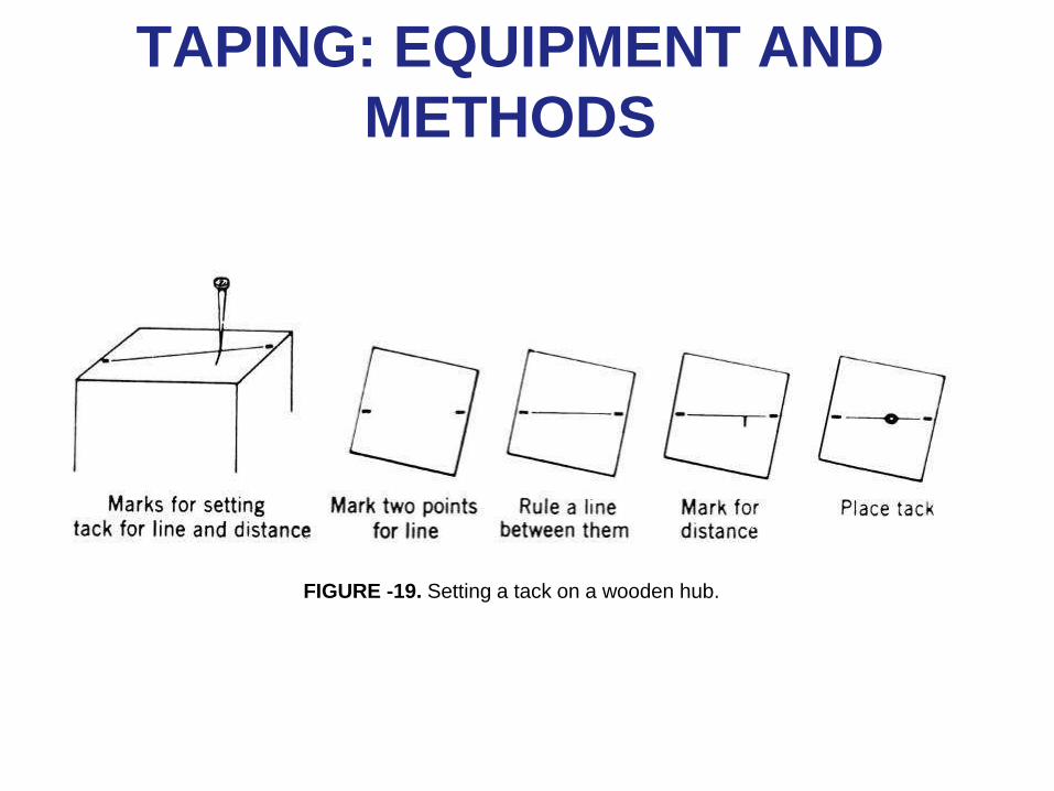
FIGURE -19. Setting a tack on a wooden hub.
TAPING: EQUIPMENT AND
METHODS
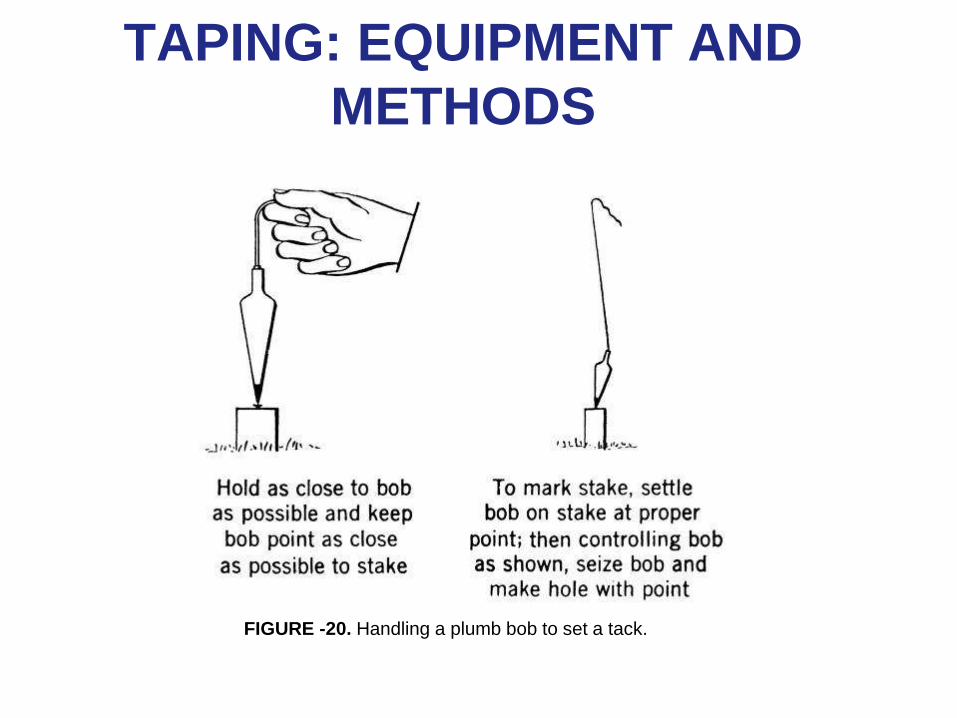
FIGURE -20. Handling a plumb bob to set a tack.
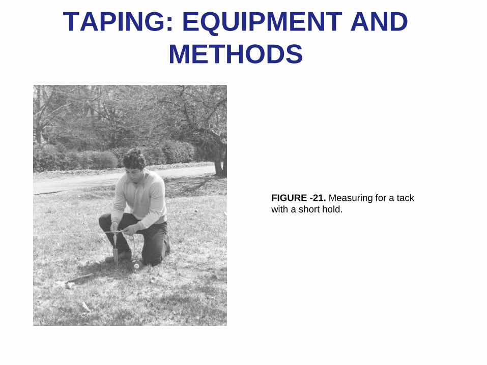
TAPING: EQUIPMENT AND
METHODS
FIGURE -21. Measuring for a tack
with a short hold.
TAPING MISTAKES, ERRORS,
AND CORRECTIONS
• Taping Mistakes or Blunders
– Misreading the tape
– Misrecording the reading
– Mistaking the endpoint of the tape
– Miscounting full tape lengths
– Mistaking station markers
TAPING MISTAKES, ERRORS,
AND CORRECTIONS
• Taping Errors
• Correction of Systematic Errors
– Common Tape Corrections
– Correction for Tape Length
– Use of CL for Correct Distance
– The Sign of the Tape Length Correction
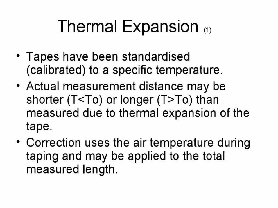
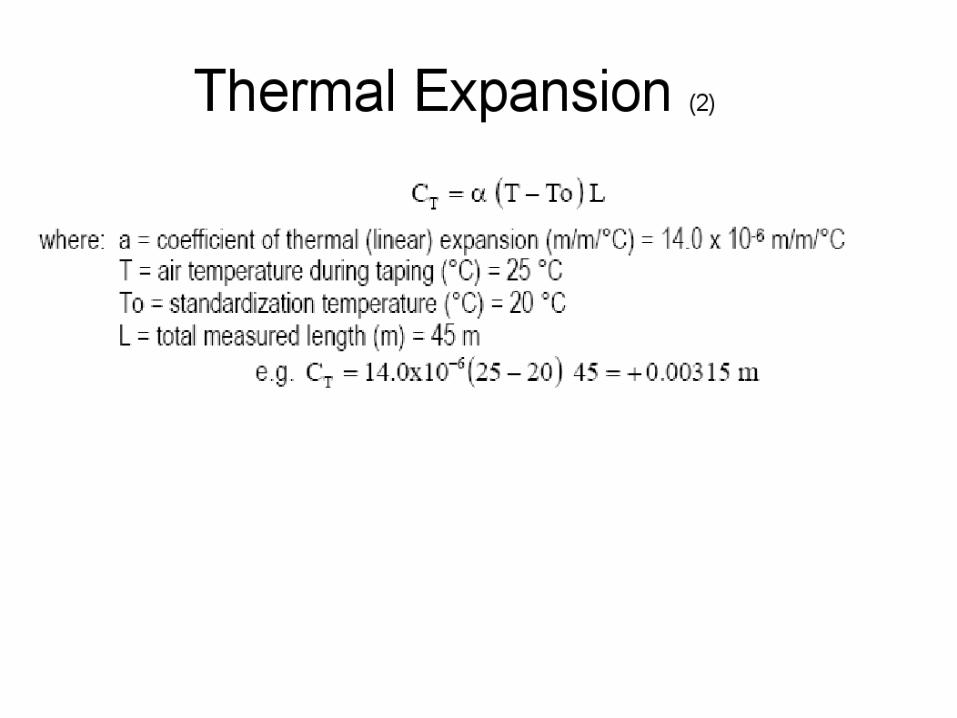
– Correction for Temperature
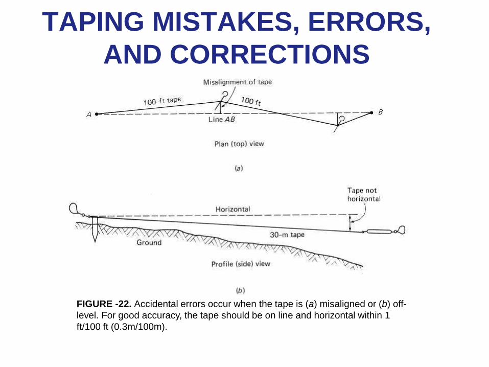
TAPING MISTAKES, ERRORS,
AND CORRECTIONS
FIGURE -22. Accidental errors occur when the tape is (a) misaligned or (b) off-
level. For good accuracy, the tape should be on line and horizontal within 1
ft/100 ft (0.3m/100m).
TAPING MISTAKES, ERRORS,
AND CORRECTIONS
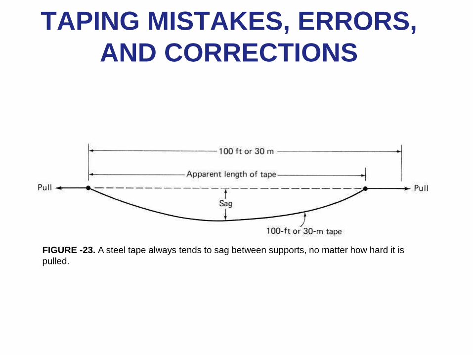
FIGURE -23. A steel tape always tends to sag between supports, no matter how hard it is
pulled.
TAPING MISTAKES, ERRORS,
AND CORRECTIONS
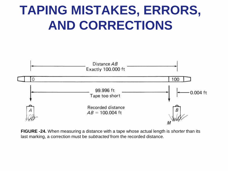
FIGURE -24. When measuring a distance with a tape whose actual length is shorter than its
last marking, a correction must be subtracted from the recorded distance.
ELECTRONIC DISTANCE
MEASUREMENT
• Electronic distance measurement (EDM) is the measurement method of choice not only for large-scale geodetic surveys but also for ordinary plane surveys.
– Compared with taping, EDM offers the advantages of increased speed, accuracy, and dollar economy when routinely determining or setting relatively long horizontal distances.
ELECTRONIC DISTANCE
MEASUREMENT
• Types of EDMIs
– Reflecting Prisms
– Accuracy of EDM
• EDMI Operating Procedure
– Setting a Mark with EDM
ELECTRONIC DISTANCE
MEASUREMENT
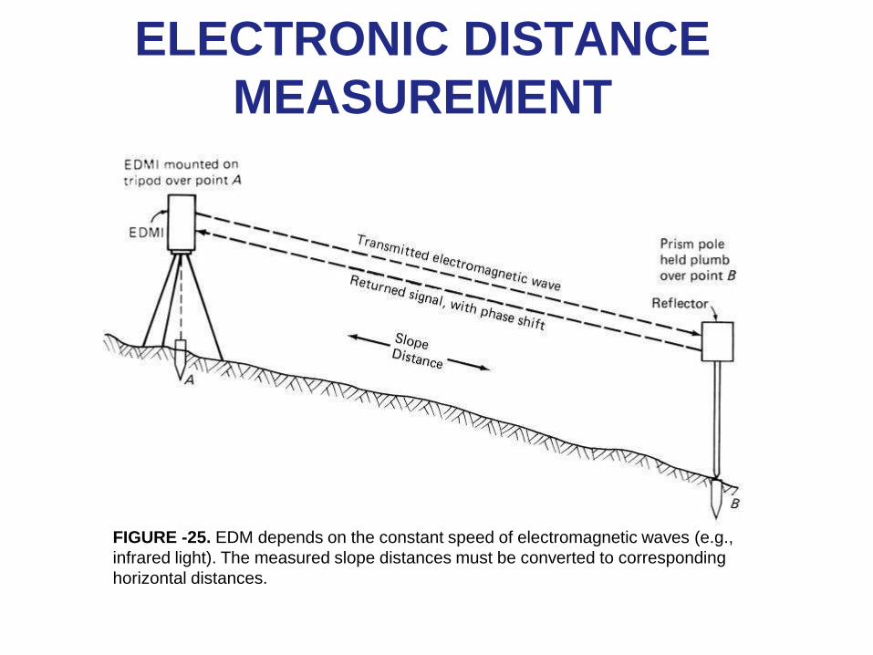
FIGURE -25. EDM depends on the constant speed of electromagnetic waves (e.g.,
infrared light). The measured slope distances must be converted to corresponding
horizontal distances.
ELECTRONIC DISTANCE
MEASUREMENT
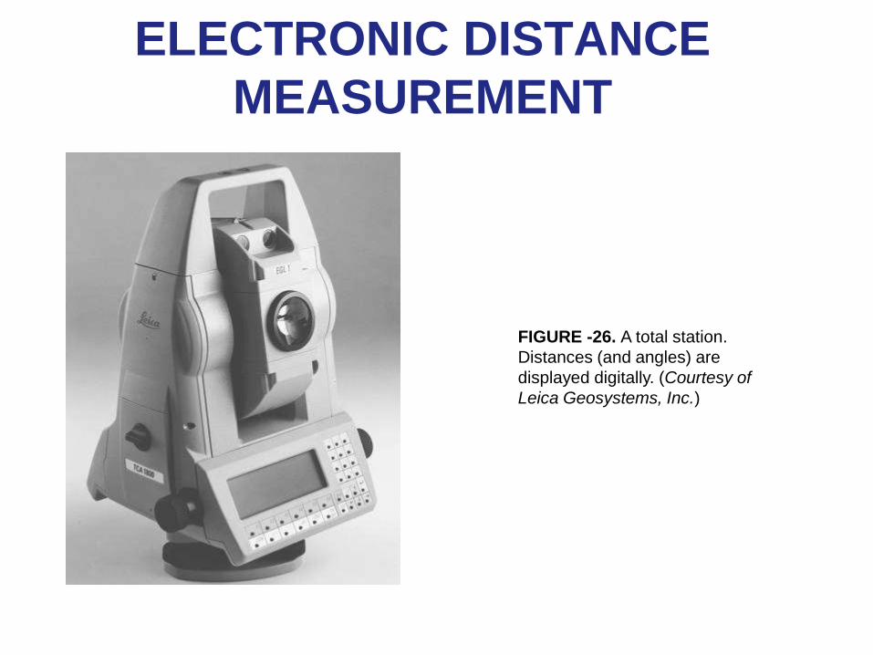
FIGURE -26. A total station.
Distances (and angles) are
displayed digitally. (Courtesy of
Leica Geosystems, Inc.)
ELECTRONIC DISTANCE
MEASUREMENT
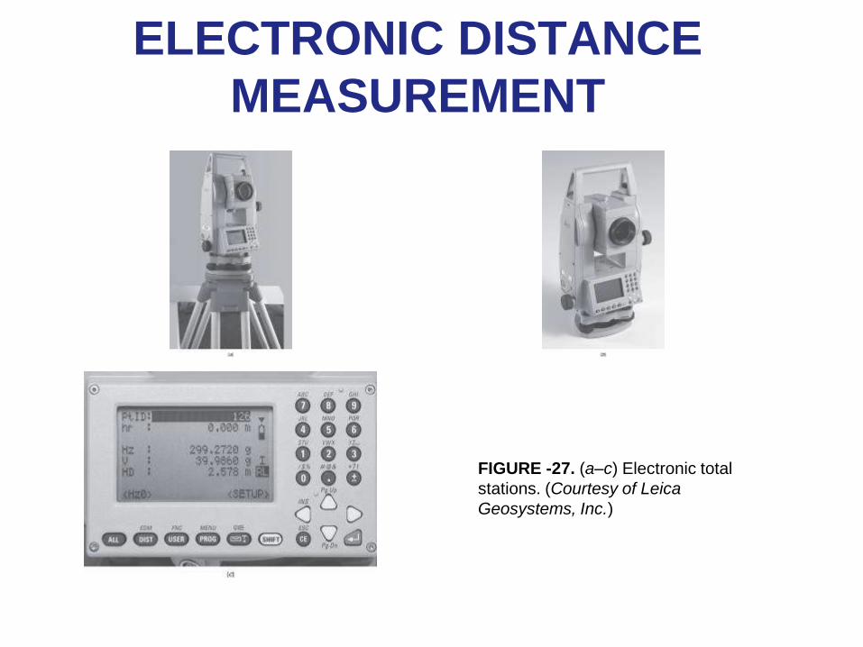
FIGURE -27. (a–c) Electronic total
stations. (Courtesy of Leica
Geosystems, Inc.)
ELECTRONIC DISTANCE
MEASUREMENT
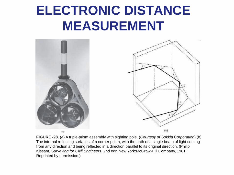
FIGURE -28. (a) A triple-prism assembly with sighting pole. (Courtesy of Sokkia Corporation) (b)
The internal reflecting surfaces of a corner prism, with the path of a single beam of light coming
from any direction and being reflected in a direction parallel to its original direction. (Philip
Kissam, Surveying for Civil Engineers, 2nd edn,New York:McGraw-Hill Company, 1981.
Reprinted by permission.)
ELECTRONIC DISTANCE
MEASUREMENT
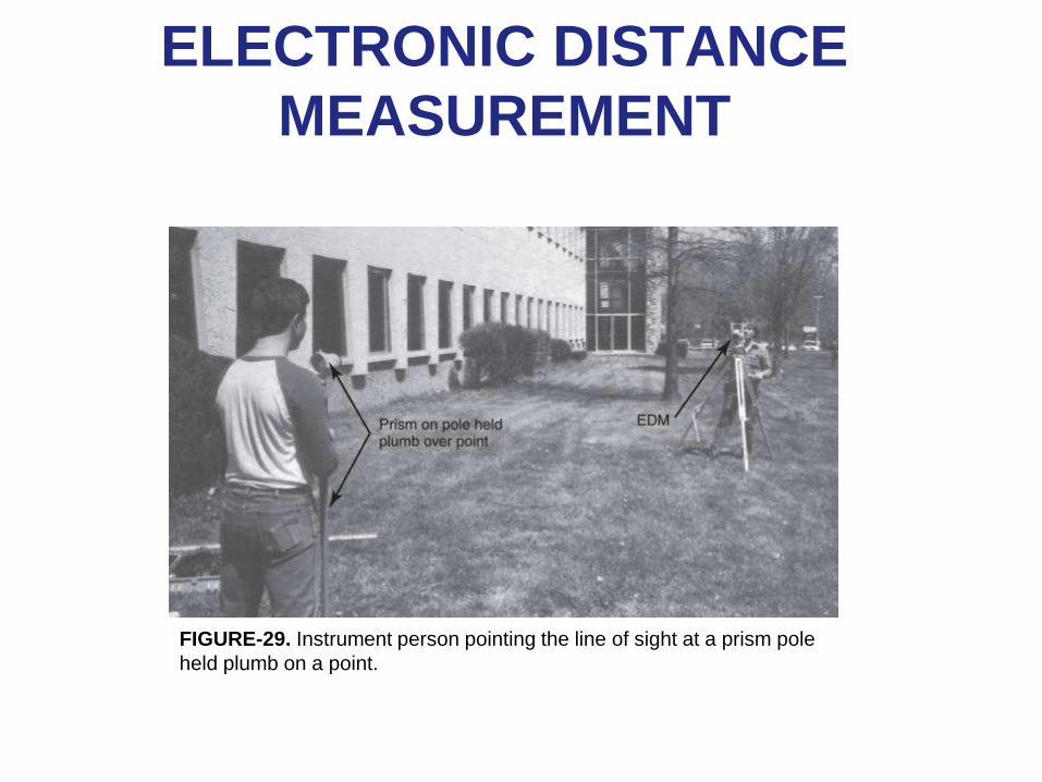
FIGURE-29. Instrument person pointing the line of sight at a prism pole
held plumb on a point.
Taping Corrections
47
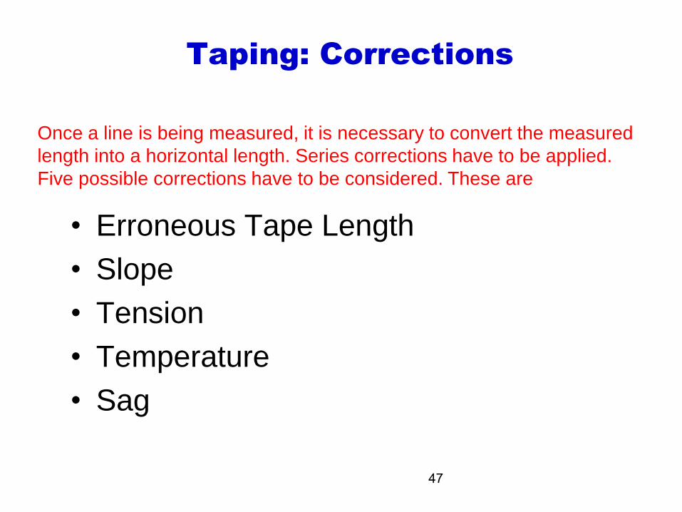
Taping: Corrections
• Erroneous Tape Length
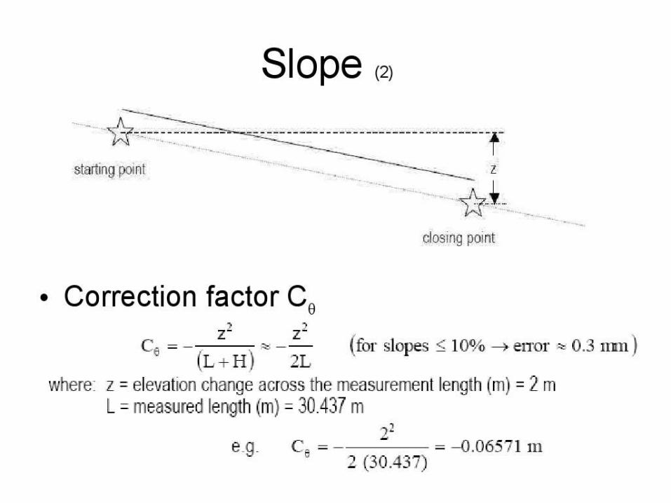
• Slope
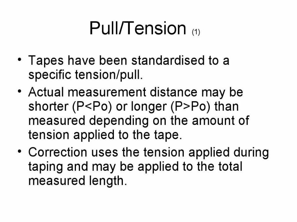
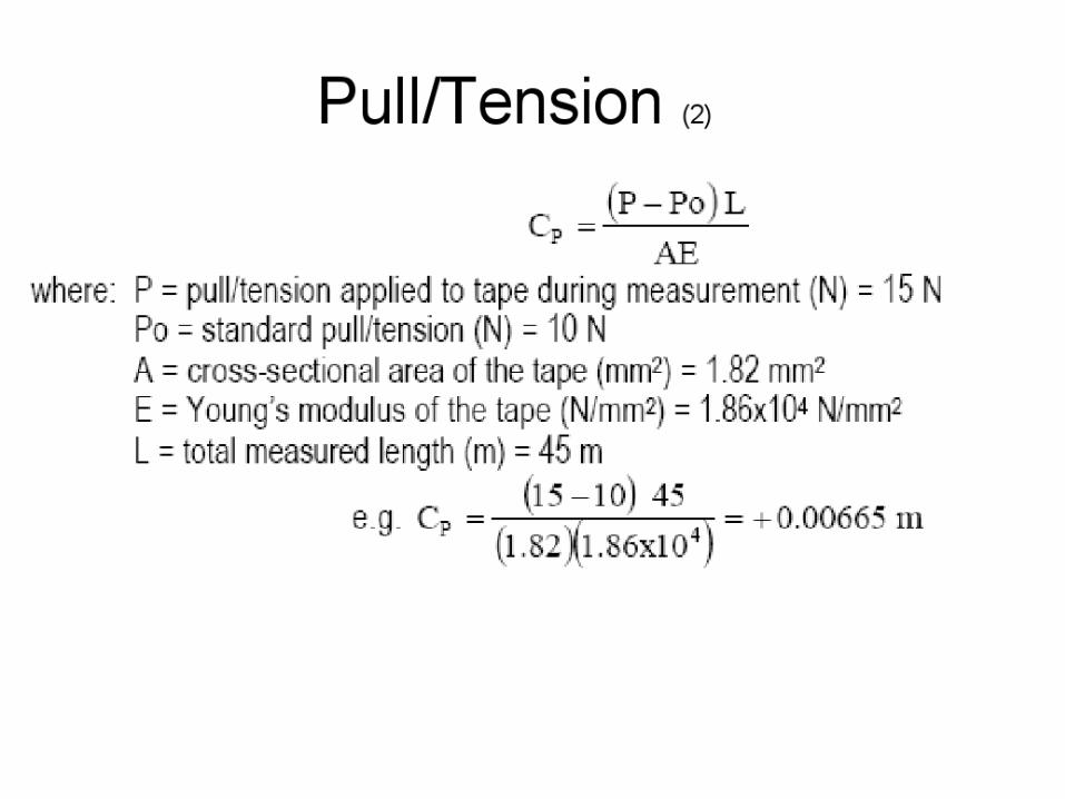
• Tension
• Temperature
• Sag
Once a line is being measured, it is necessary to convert the measured
length into a horizontal length. Series corrections have to be applied.
Five possible corrections have to be considered. These are
48
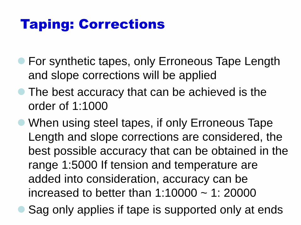
Taping: Corrections
For synthetic tapes, only Erroneous Tape Length
and slope corrections will be applied
The best accuracy that can be achieved is the
order of 1:1000
When using steel tapes, if only Erroneous Tape
Length and slope corrections are considered, the
best possible accuracy that can be obtained in the
range 1:5000 If tension and temperature are
added into consideration, accuracy can be
increased to better than 1:10000 ~ 1: 20000
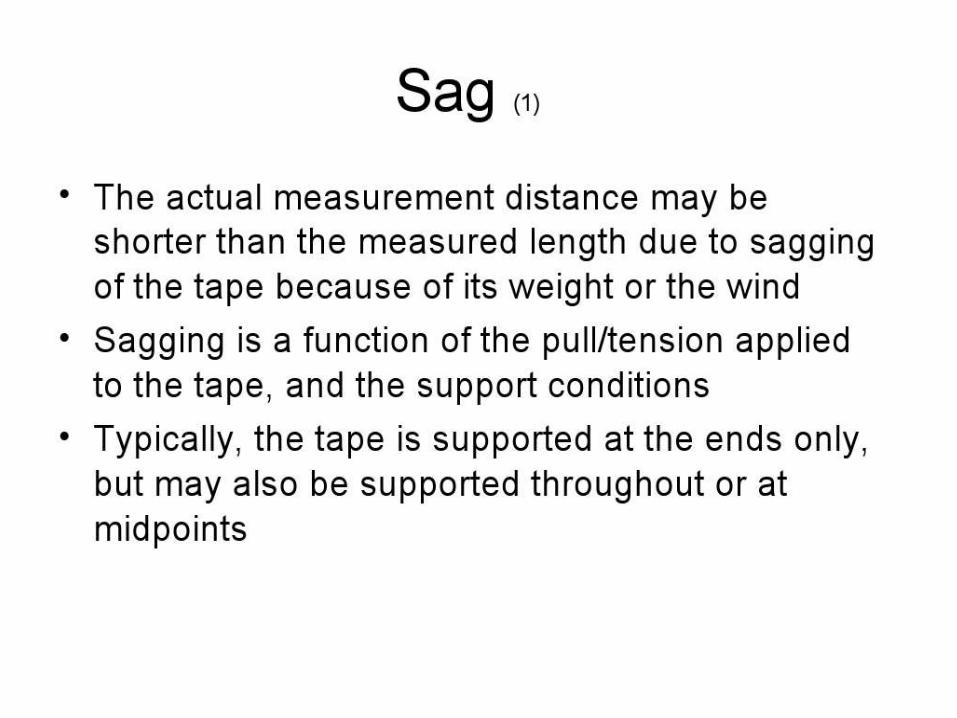
Sag only applies if tape is supported only at ends
49
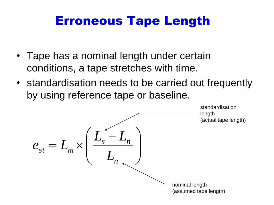
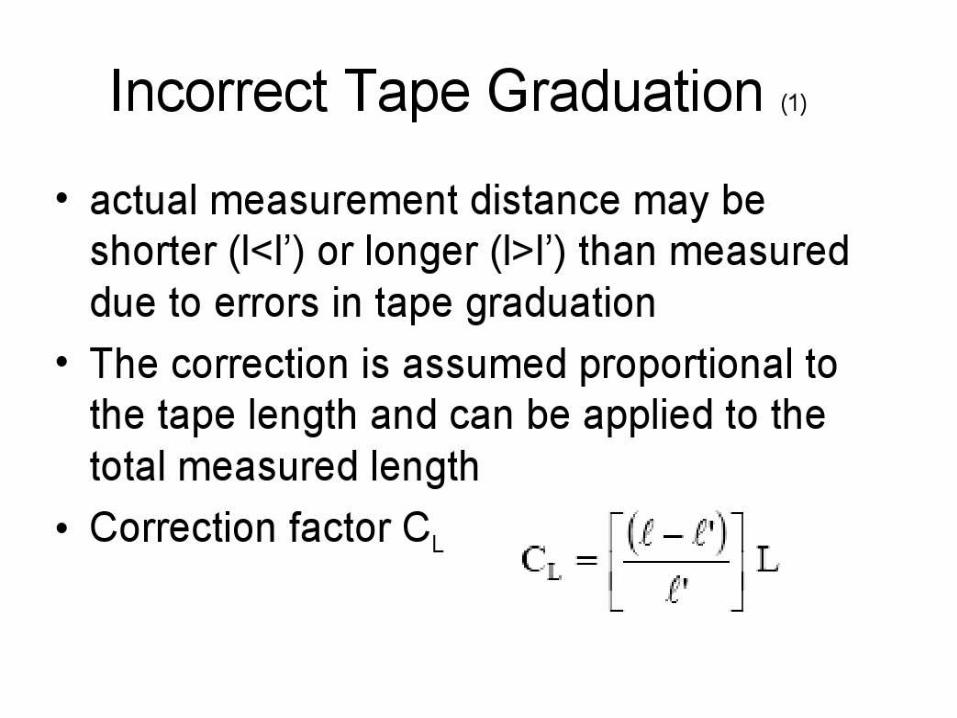
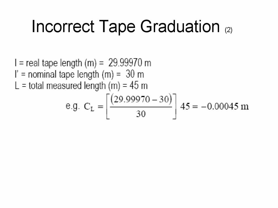
Erroneous Tape Length
• Tape has a nominal length under certain
conditions, a tape stretches with time.
• standardisation needs to be carried out frequently
by using reference tape or baseline.
n
nsmst
L
LLLe
standardisation
length
(actual tape length)
nominal length
(assumed tape length)
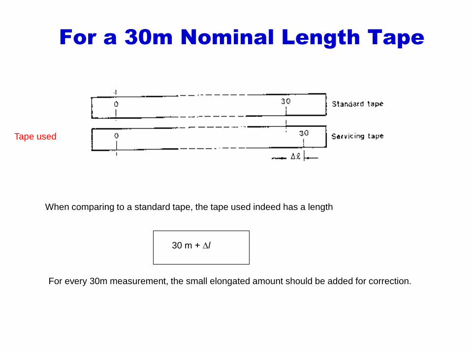
For a 30m Nominal Length Tape
Tape used
When comparing to a standard tape, the tape used indeed has a length
For every 30m measurement, the small elongated amount should be added for correction.
30 m + ∆l
60
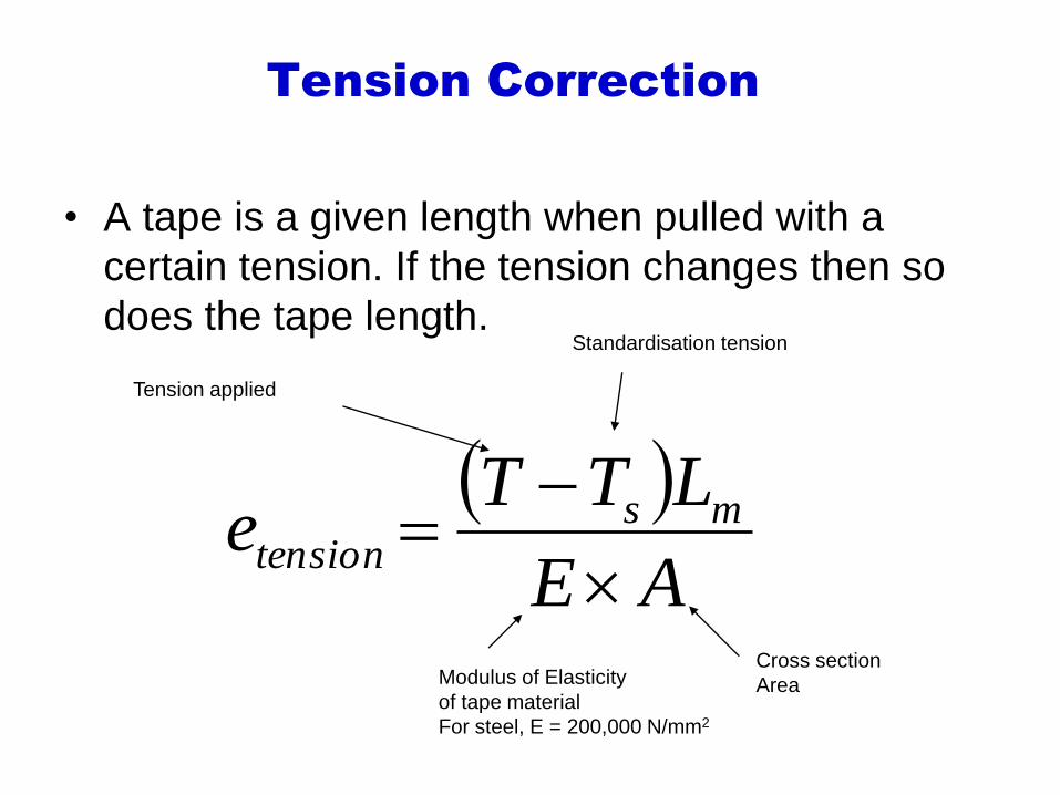
Tension Correction
• A tape is a given length when pulled with a
certain tension. If the tension changes then so
does the tape length.
AE
LTTe ms
tension
Standardisation tension
Modulus of Elasticity
of tape material
For steel, E = 200,000 N/mm2
Cross section
Area
Tension applied
63
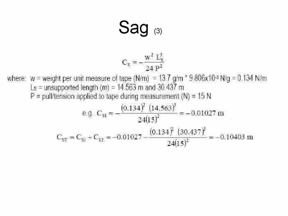
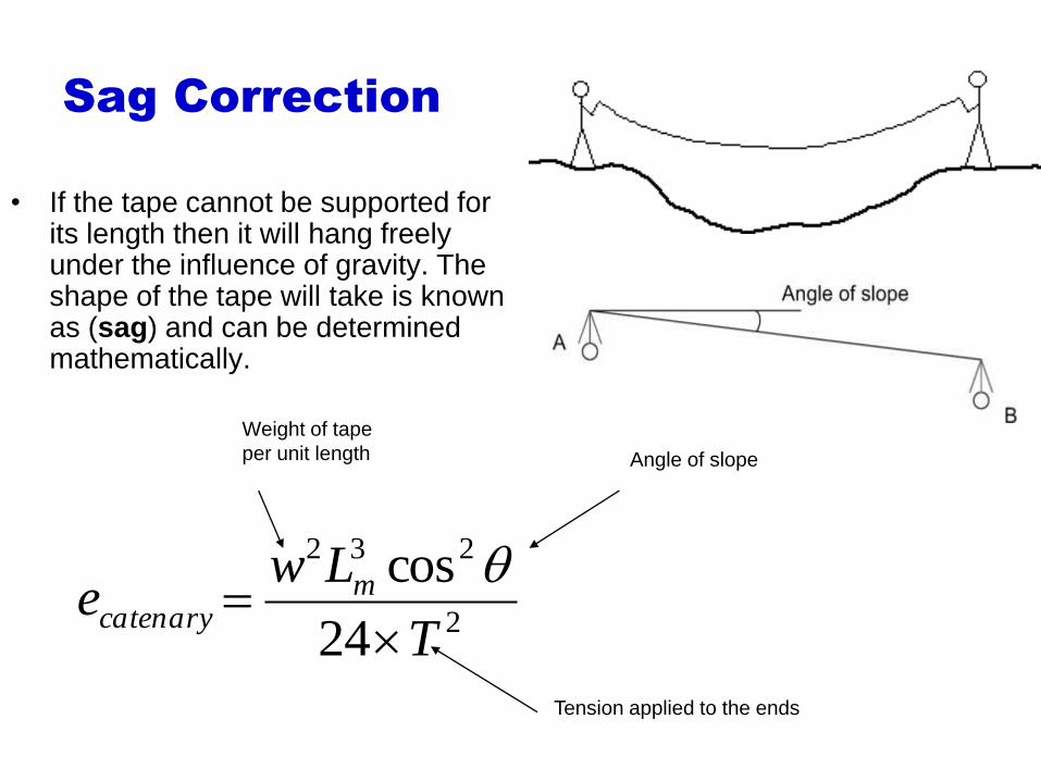
Sag Correction
• If the tape cannot be supported for its length then it will hang freely under the influence of gravity. The shape of the tape will take is known as (sag) and can be determined mathematically.
2
232
24
cos
T
Lwe m
catenary
Tension applied to the ends
Angle of slope
Weight of tape
per unit length
66
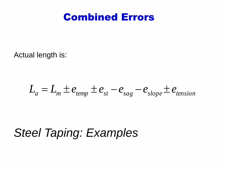
Combined Errors
tensionslopesagsttempma eeeeeLL
Actual length is:
Steel Taping: Examples


