PERFORMANCE EVALUATION OF A ZERO-FOULING RECIPROCATING SCRAPED
SURFACE HEAT EXCHANGER
J.P. Solano1, A. García1, P.G. Vicente2 and A. Viedma1
1 Universidad Politécnica de Cartagena. Departamento de Ingeniería Térmica y de Fluidos.Campus Muralla del Mar 30202 Cartagena (Spain) E-mail: [email protected]
2 Universidad Miguel Hernández. Departamento de Ingeniería de Sistemas IndustrialesEdificio Torreblanca. Avda del Ferrocarril, s/n 03202 Elche (Spain)
ABSTRACTAn innovative self-cleaning shell and tube heat
exchanger is presented. Inside each interior tube (throughwhich the product flows) a scraping rod is fitted. This rodmoves in reciprocal manner and the scraping elementsmounted on the rod fully clean the tube wall surface.Additionally, the macroscopic displacements of the flow,induced by the insert device motion, promote high flowmixing. Consequently, tube-side heat transfer coefficientsare enhanced.
Thermal-hydraulic and scraping power measurementsare performed in laminar regime for 20<Reh<250 and0≤ω≤1 (ω=uscr /uf ). An extended Performance Evaluation
Criterion is proposed, in order to balance the augmentationsof heat transfer and the increased power consumption(pumping and scraping power) of the device. This studyallows stating guidelines for the operation of the device,concluding that the performance of the heat exchanger isirrespective of the velocity ratio. The scraper can be usedintermittently, or at the minimum scraping frequency thatensures fouling mitigation.
INTRODUCTIONHeat transfer processes in the food and chemical
industries frequently deal with highly viscous liquids. The performance of heat exchangers working under these
conditions is usually low, as a result of the characteristics of the encountered laminar regime (Webb and Kim, 2005).Moreover, the heat transfer surfaces may become coatedwith a deposit of solid material after a period of operation.This phenomenon, known as fouling, causes a reducedoverall heat transfer coefficient (Bergles, 2002). Heatexchangers are generally over-designed to compensate for the anticipated fouling. Moreover, cleaning operationsdecrease equipment availability, which causes as well aconsiderable economic impact (Steinhagen et al., 1992).
Among the several technical solutions for foulingcleaning and prevention (Müller-Steinhagen, 2000),mechanically assisted heat exchangers, where a heat transfer surface is periodically scraped by a moving element,constitute a suitable solution for applications with severetendency to fouling and low heat transfer rates. Dynamicheat exchangers with rotating scraping blades (SSHE) are
found in commercial practice: they prevent fouling and promote mixing and heat transfer. Many investigations havefocused on these anti-fouling devices, studying flow patterncharacteristics (Trommelen and Beek, 1971), their thermal-hydraulic performance (De Goede and De Jong, 1993) or scraping efficiency (Matsunaga et al., 2003).
This work presents an innovative scraped surface heatexchanger. This equipment is mechanically assisted by areciprocating cylinder, that moves the scraping rods insertedin each of the interior tubes. An array of semi-circular elements is mounted on each rod, with a pitch p=5D. Theseelements fit the internal diameter of the tubes. During thereciprocating motion, they scrape the inner tube wall,avoiding fouling.
Additionally, the movement of the inserted devicegenerates macroscopic displacements of the flow, thatcontinuously mix core regions with peripheral flow. As aresult of the mentioned features, the reciprocating scrapedsurface heat exchanger provides high overall heat transfer coefficients, and prevents down time for cleaningoperations.
progressively being introduced in the food industry,wastewater treatment processes, production of second-generation biofuels, etc. It founds its most practicalapplication under severe fouling tendency, whereobstruction of the tubes occur in few hours if no cleaningstrategies are adopted.
Depending on the severity of the fouling phenomenon,the scraper can be either activated intermittently, or movecontinuously in a wide range of scraping velocities. Thisvariety of operating conditions yields to different heattransfer and pressure drop characteristics (Solano et al.,2006), as well as scraping power consumption. Acharacterization of the heat exchanger performance isnecessary to assess the relation between heat transfer enhancement and augmentation of power consumption(pumping and scraping) in the heat exchanger, provided thattube walls keep clean in all the regimes.
To accomplish with this requirement, a thouroughexperimental work has been developed. Pressure drop,
scraping power and heat transfer measurements are obtainedin laminar regime for Reynolds numbers 20<Reh<250 andvelocity ratios 0≤ω≤1 (ω=uscr /uf ).
Performance Evaluation Criterion R3 (Bergles et al.,1974) has been extended to account for the scraping power consumption. This evaluation allows stating the heatexchange increase obtained when a scraper is introduced ina tubular heat exchanger, while keeping constant the heattransfer area and global power consumption. The presenceof fouling in the smooth tubes of the heat exchanger havealso been considered in the formulation of this criterion.
EXPERIMENTAL SET-UP
A schematic diagram of the experimental setup isshown in Fig. 2. The test section consists of a smooth tubewhere the scraper is inserted. A hydraulic units provides theinsert device with reciprocating motion. A secondary circuitis used for regulating the working fluid temperature.Propylene-glycol is employed as working fluid. A detail of the scraper geometry is shown in Fig. 3 and Fig. 4. Itconsists of lightened semicircular plugs, aimed at reducingthe blockage effect experienced by the flow.
frequency
converter
coriolis
flowmeter
electric
heater centrifugal pumps
cooling
fluid
working
fluid
plate
heat
exchanger
transformer
pressure transducer
hydraulic
piston
PID
RTD
piezorresistive
transducers
cooling
machine
Fig. 2 Experimental facility for thermal-hydraulic and
power consumption measurements
Fig. 3. Sketch of the reciprocating scraper
Fanning friction factorPressure drop tests were carried out in the hydro-
dynamically developed region under isothermal conditions.Fanning friction factor were determined from fluid massflow rate and mean pressure drop measurements by meansof
( )2
322
32m
Dd D P f h
ph
&l
+Δ=
π ρ (1)
Time-dependent pressure during the scraping processwas measured in two sections of the tube separated by adistance ℓ p=1.8 m. Two piezorresistive pressure sensors(Kistler K-Line) were connected to each tube section withfour pressure taps separated by 90º. Mean pressure drop inthe tube over the scraping cycle, P Δ , was computed byintegration of the instantaneous signal over 50 cycles.
Fig. 4. Geometry of the scraping plug
Scraping power
Scraping power consumption was obtained measuringthe time-dependent pressure in both chambers of thedouble-effect hydraulic piston, as
( )24
22
t
P D DS W
piston pc
scr Δ
Δ−=π
& (2)
Two pizorresistive Kistler K-Line pressure sensors with20 bar measuring range were employed. Scraping period t Δ was measured with a temporizer connected to final-strokeswitches, that constrained the scraping amplitude to thevalue S=10D.
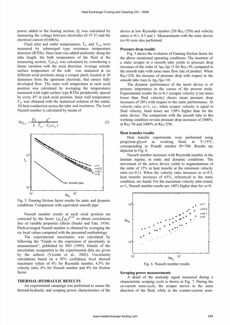
Nusselt number
Heat transfer experiments were carried out under uniform heat flux conditions, where energy was added tothe working fluid by Joule effect heating. A 6 kVAtransformer was connected to the smooth tube by copper electrodes and power supply was regulated by means of anauto-transformer. The length between electrodes defined theheat transfer test section (ℓh = 1 m). The overall electrical
Solano et al. / Performance Evaluation of a Zero-Fouling …
www.heatexchanger-fouling.com 393
7/27/2019 55_Solano_F Performance Evaluation of a Zero Fouling Heat Exchanger
cycle, the direction of the scraper movement is contrary tothe mean flow direction. During each semi-cycle, aninternal valve diverts the oil at the impulse pressure to thecorresponding chamber of the double-effect piston, whilethe other chamber drains the remaining oil towards thedeposit of the hydraulic unit (discharge pressure). The
pressure difference between both chambers is employed inEq. (2) to compute the scraping power at each semi-cycle.The main forces overcome by the hydraulic piston are dueto the friction between the scraping plugs and the inner tubewall. This tribological nature prevents from obtaining non-dimensional results from these experimental data.
Mean scraping power results are shown in Fig. 8 for velocity ratios ω=0.1, 0.5 and 1, and flow rate ranging from60 to 1300 l/h. Scraper velocity plays a fundamental role inthe scraping power consumption. For any constant velocityratio, as flow rate increases, scraper velocity increases withthe relation uscr =ω×uf . This characteristic is observed in thehigher dependence of scraping power on the flow rate for
increasing velocity ratios. For flow rate 300 l/h and velocityratio ω=0.1, scraping power is Ẇscr ≈8 W, while for ω=1,Ẇscr ≈55 W (600% higher).
15 20 25 30
0
2
4
6
time(s)
p ( b a r )
pcc
(t)
peq
(t)
15 20 25 30
0
2
4
6
discharge pressure
impulse pressure
co-current counter-current
Fig. 7 Pressure signal in both piston chambers, during acharacteristics scraping cycle
0 250 500 750 1000 12500
20
40
60
Flow Rate (l/h)
S c r a p i n g P o w e r ( W
)
ω=0.1
ω=0.5ω=1
Fig. 8. Scraping power measurements
The pumping power Ẇ p (Eq. 4) along the scrapingsection, ℓ scr , is computed as follows:
( ) scr f h p u
d D f W l& 3
2ρ
π += (4)
This definition allows obtaining the scraping-to- pumping power ratio, as shown in Fig. 9. This relationdiminishes for increasing flow rates, which indicates theimportant contribution of the pressure drop in the power consumption of the dynamic heat exchanger at high flowrates.
102
103
10-1
100
101
102
Flow Rate (l/h)
W s c r
/ W
p
ω=0.1
ω=0.5
ω=1
Fig. 9. Scraping-to-pumping power ratio
PERFORMANCE EVALUATION CRITERIAPrevious thermal-hydraulic results show the heat
transfer augmentation associated to the operation of thedynamic heat exchanger at growing velocity ratios.However, a huge increase in pressure drop and scraping
power consumption also follows these working conditions.The self-cleaning characteristic of this type of heat
exchanger justifies its employment in applications withsevere tendency to fouling. Nevertheless, a quantitativemethod is necessary to assess the benefits of the severaloperating conditions of the heat exchanger on its global performance.
To cope with this necessity, Performance EvaluationCriteria, defined by Bergles et al. (1974) and Webb (1981),can be employed. The extension of the classical formulationto account for the increased power consumption of reciprocating scraped surface heat exchangers is proposed.
Extension of Criterion R3Criterion R3 accounts for the heat transfer
augmentation obtained when a reciprocating scraper isinserted in a smooth tube, for equal heat transfer area and power consumption. Some aspects should be pointed out:
1. The logarithmic mean temperature difference inthe heat exchanger remains unchanged.
2. Shell-side heat transfer resistances and conductionthrough the tubes are negligible.
3. Power consumption in the smooth tube refers to pumping power.
4. Power consumption in the augmented heatexchanger is the sum of pumping power andscraping power.
Solano et al. / Performance Evaluation of a Zero-Fouling …
www.heatexchanger-fouling.com 395
7/27/2019 55_Solano_F Performance Evaluation of a Zero Fouling Heat Exchanger
Eq. 5 relates the heat transfer coefficient in the tubeside of the reciprocating scraped surface heat exchanger with the heat transfer coefficient in the equivalent smooth pipe. However, a further extension of this formulation can be done if the existence of a fouling resistance (R f ) in thesmooth tube is considered:
i
f
i se s A
R
Ah AU +=
11(6)
Being R3=Ua/Us, substitution of Eq. 6 yields:
T W N h
f s
s
ha
D
k R Nu D
Nu
Nu R
Δ⎟⎟ ⎠
⎞⎜⎜⎝
⎛ +=
,,,
,3&l
(7)
In Eqs. (5) and (7), Nus is the Nusselt number in thesmooth pipe evaluated at the equivalent Reynolds number Res, which is subjected to the constraint of equal power consumption in both smooth and augmented tubes:
( )⎟⎟
⎠
⎞
⎜⎜
⎝
⎛ +
+= scr
scr
scr
h
haha
s
s W D
D
d D D f
f &
l
l3
22
3
2
,3
,3 2
Re1
Reμ
ρ
π (8)
Considering the thermal entry effects observed withinhigh Prandtl flows, Pethukov and Polyakov (1988)correlation will be employed for Res<2300. It allowscomputing smooth tube mean Nusselt number in laminar regime, as a function of non-dimensional length x*:
*x1331s e*)x(31.136.4 Nu −+= (9)
101
102
103
104
105
101
102
103
104
Res
Nus
Pr=150
Pr=300
Pr=700
LAMINAR FLOW
Pethukov y Poliakov [1988]
TURBULENT FLOW
Gnielinski [1976]
SMOOTH PIPE
Fig. 10 Nusselt number in a smooth pipe, with correlationsof Pethukov and Polyakov (laminar) and Gnielinski(turbulent)
In turbulent regime, the correlation proposed byGnielinski (1976) is employed, relating Nusselt number with Reynolds number and Prandtl number:
( ) ( )
)1(Pr 27.121
Pr 1000Re232 −+
−
= s
s
s f
f
Nu (10)
A graphical representation of Eqs. (9) and (10) isdepicted in Fig. 10.
Results and discussionR3 extended criterion has been computed with Eqs. (5)
and (7). The graphical representation is shown in Fig. 11.Results obtained with Eq. (5) relate heat transfer in the
augmented geometry with heat transfer in a clean smoothtube. Augmentations of heat transfer between 2 and 5 timesare found when the scraper works as static insert device.
In dynamic conditions, the device yields to enhanced performance (R3>1) for Res>400. Maximum augmentationsin heat transfer of 2.5 times are found for Res≈2000. Theresults are irrespective of the velocity ratio. This behavior highlights the counteracting effect of the increased pumpingand scraping power on the heat transfer enhancement.Furthermore, the better performance shown in staticconditions confirms the dramatic effect of scraping power,specially at low Reynolds number.
101
102
103
104
0
1
2
4
6
8
Res
R3
ω=0
ω=0.1
ω=0.5
ω=1
Eq. (7)
Rf =2.5·10
-3m
2K/W
Eq. (5)
Rf =0
Fig. 11. R3 extended performance evaluation factor.Comparison with clean smooth tubes (black) and fouledsmooth tubes (red)
A fouling resistance R f =2.5·10-3 m2 K/W is consideredfor the smooth tubes in Eq. (7), according to theexperimental results of Chen et al. (2003) for milk fouling.In this case, R3 factor is around 85% higher than the previous results. It allows stating the combined utility of thereciprocating scraper as heat transfer promoter due tomixing and fouling mitigation. Under these conditions,maximum heat transfer augmentations R3=5 are found in
dynamic conditions.The poor differences in performance of the device for different velocity ratios entail that the associated heat
Heat Exchanger Fouling and Cleaning VIII – 2009
www.heatexchanger-fouling.com 396
7/27/2019 55_Solano_F Performance Evaluation of a Zero Fouling Heat Exchanger
transfer enhancement is counteracted by the unacceptable pressure drop and scraping power increase. Thus, it isrecommended to activate the scraper intermittently for cleaning operations. In this case, the scraper will act as astatic mixer during most of the operating time, enhancingheat transfer, while power consumption of the equipment is
minimized. If fouling conditions are severe, the scraper should work in continuous regime at the minimumfrequency that ensures fouling mitigation.
CONCLUSIONS
1. Thermal-hydraulic and scraping power measurements have been performed in aninnovative reciprocating scraped surface heatexchanger, for a wide range of working conditions.
2. Maximum augmentations of pressure drop of 150% have been found when the scraper moveswith velocity ratio ω=1, with respect to the static
conditions. Heat transfer augments 140% in thisoperating range. Scraping power shows a strongdependency on scraper velocity.
3. A new formulation of R3 criteria, that accounts for the scraping power, has been proposed. Thecomparison with a fouled smooth tube has also been stated.
4. Heat transfer augmentations up to 5 times arefound for the static device, according to R3criterion. If compared to the fouled smooth tube,this factor arises to 8, for laminar regime.
5. The performance of the dynamic is irrespective of the velocity ratio, and lower in every working
conditions to the static results. Thus, the scraper should work intermittenly, for cleaning operations,or continuously with the minimum scrapingfrequency, to minimize power consumption.
NOMENCLATUREc p specific heat (J kg-1 K -1)D tube inner diameter (m)Dh hydraulic diameter (m)Dc piston chamber diameter (m)D p piston diameter (m)d rod diameter (minimum inner) (m) p pitch of the insert devices (m)h heat transfer coefficient (W m-2K -1)k thermal conductivity (W m-1K -1)ℓ p length between pressure taps (m)ℓh length of the heat transfer section (m)ℓscr length of the scraper (m)m& mass flow rate (kg s-1)
P Δ time averaged pressure drop (Pa)t Δ scraping period (s)
Q overall electrical power added (W)Q1 heat losses in the test section (W)q” heat flux (W m-2)T temperature (K)
S scraping amplitude (m)uf mean fluid velocity, (m/s)
uscr mean scraping velocity, (m/s)Ẇscr scraping power (W)Ẇ p pumping power (W)x p measuring point axial position (m)x* non-dimensional length, x/(D·Re·Pr) [-]f h Fanning friction factor, ΔP Dh/(2 ρuf
Subscripts b based on bulk temperaturescr scraper f fluidc hydraulic chamber in tube inlet
out tube outletw based on inside wall temperature
REFERENCESBergles, A.E., Blumenkrantz, A.R., and Taborek, J.,
1974, Performance evaluation criteria for enhanced heattransfer surfaces, Journal of Heat Transfer, Vol. 2, pp. 239– 243.
Bergles, A.E., 2002, ExHFT for fourth generation heattransfer technology, Experimental Thermal and Fluid Science, Vol. 26, pp. 335-344.
Chen, X.D., Li, D.X.Y., Lin, S.X.Q., and Özkan, N.,2003, On-line fouling/cleaning detection by measuring
electric resistance- equipment development and applicationto milk fouling detection and chemical cleaning monitoring, Journal of Food Engineering, Vol. 61, pp. 181-189.
De Goede, R., De Jong, E.J., 1993, Heat transfer properties of a scraped-surface heat exchanger in theturbulent flow regime, Chemical Engineering Science, Vol.48, No. 8, pp.1393-1404.
Gnielinski, V., 1976, New equations for heat and masstransfer in turbulent pipe and channel flow, International
Chemical Engineering, Vol. 16, pp. 359-368.Matsunaga, T., Roh, M. and Kamota, T., 2003, Heat
transfer and power consumption in a scraped surface heatexchanger, International Institute of Refrigeration,
Washington D.C., USA.Müller-Steinhagen, H., 2000, Handbook of Heat
Exchanger Fouling – Mitigation and Cleaning Technologies, Publico Publications.
Petukhov, B.S., and Polyakov, A.F., 1988, Heat Transfer in Turbulent Mixed Convection, first ed.,Hemisphere Publishing, New York, USA.
Solano, J.P., García, A., Vicente, P.G., and Viedma, A.,2006, Experimental study of heat transfer and pressure dropin mechanically-assisted heat exchangers with activescrapers, Proc. 13
th Int. Heat Transfer Conference 2006, Sydney, Australia.
Steinhagen, R., Müller-Steinhagen, H., and Maani, K.,1992, Problems and costs due to heat exchanger fouling in
Solano et al. / Performance Evaluation of a Zero-Fouling …
www.heatexchanger-fouling.com 397
7/27/2019 55_Solano_F Performance Evaluation of a Zero Fouling Heat Exchanger
New Zealand industries, Heat Transfer Engineering, Vol.14, pp. 19-30.
Trommelen, A.M., and Beek, W.J., 1971, Flow phenomena in a scraped surface heat exchanger, Chemical Engineering Science, Vol. 26, pp. 1933-1941.
Wang, W., Walt, J.H., McCarthy, K.L., Flow profiles
of power law fluids in scraped surface heat exchanger geometry using MRI, Journal of Food Process Engineering,Vol. 22, pp 11-27, 1999.
Webb, R.L., and Kim, N., 2005, Principles of Enhanced Heat Transfer, Taylor and Francis, New York,USA
Webb, R.L., 1981, Performance evaluation criteria for used of enhanced heat transfer surfaces in heat exchanger design, International Journal of Heat and Mass Transfer,
Vol. 24, pp. 715-726Sieder, E.N., y Tate, E.G., Heat transfer and pressure
drop of liquids in tubes, Ind. Eng. Chem., Vol. 28, p. 1429.1936.
ISO, 1995, Guide to the Expression of Uncertainty in Measurement, first ed., International Organization for Standardization, Switzerland.
Vicente, P.G., García, A., Viedma, A., 2002,Experimental study of mixed convection and pressure dropin helically dimpled tubes for laminar and transition flow, International Journal of Heat and Mass Transfer, Vol. 45, pp. 5091–5105.


![Heat Exchanger Fouling and Cleaning - MODEL ...heatexchanger-fouling.com/papers/papers2019/32_Lozano F...Fouling rate is also traditionally (and incorrectly, see [13]) equated with](https://static.documents.pub/doc/80x56/5eda5de9b3745412b57139a0/heat-exchanger-fouling-and-cleaning-model-heatexchanger-f-fouling-rate.jpg)


