Manual Revision #: 10142016 AT ASSEMBLY MANUAL READ AND SAVE MANUAL FOR FUTURE REFERENCE. Assemble your grill immediately. Missing or damaged parts should be claimed within 30 days of purchase. For product inquiries, parts, warranty and troubleshooting support, please call 1-800-309-3452. www.cuisinartbbqs.com LIMITED 5-YEAR WARRANTY Cuisinart ® Ceramic 850 85-3126-2 (G53507) Propane 85-3127-0 (G53508) Natural Gas
Transcript
Manual Revision #: 10142016 AT
ASSEMBLY MANUAL
REAd ANd SAvE MANUAL foR fUtURE REfERENcE.
Assemble your grill immediately. Missing or damaged parts should be claimed within 30 days of purchase.
for product inquiries, parts, warranty and troubleshooting support, please call 1-800-309-3452.
www.cuisinartbbqs.com
LiMitEd 5-YEAR WARRANtY
cuisinart® ceramic 850 85-3126-2 (G53507) Propane85-3127-0 (G53508) Natural Gas
THIS MANUAL MUST REMAIN WITH THE PRODUCT AT ALL TIMES
1-800-309-3452
H E AV Y A R T I C L E N E E D S 2 T O L I F T
to oRdER non-warranty replacement parts or accessories, or to register your warranty, please visit us on the web at
www.cuisinartbbqs.com
T H I S B A R B E C U E I S F O R O U T D O O R U S E O N LY
cUiSiNARt® cUStoMER cARE HotLiNE
Sharp edges. Wear gloves when assembling your grill.
Read and follow all safety statements, assembly instructions, use and care directions before attempting to assemble and cook.
this manual should be kept with the BBQ at all times.
cAUtioN dANGER
dANGER
cAUtioN
cAUtioN
failure to follow all of the Manufacturer’s instructions could result in hazardous fires, explosions, property damage, or serious personal injury or even death.
follow all leak check procedures carefully prior to operation of barbecue, even if grill was dealer assembled. do not try lighting this BBQ without reading the Lighting instructions section of the Safety and care Manual that accompanies this grill.
WARNiNG
iNStALLER oR ASSEMBLER/coNSUMER
1. if you smell Gas: a. Shut off gas to the appliance b. Extinguish any open flame c. open lid d. if odor continues, keep away from the appliance and immediately call your gas supplier or your fire department
2. do not store or use gasoline or other flammable liquids or vapours in the vicinity of this or any other appliance.
3. An LP cylinder not connected for use shall not be stored in the vicinity of this or any other appliance.
1. do not store or use gasoline or other flammable liquids or vapours in the vicinity of this or any other appliance.
2. An LP cylinder not connected for use shall not be stored in the vicinity of this or any other appliance.
Avoid burns. the stainless steel and steel surfaces of this barbecue can become extremely hot, in direct sun and while the barbecue is in operation.
1
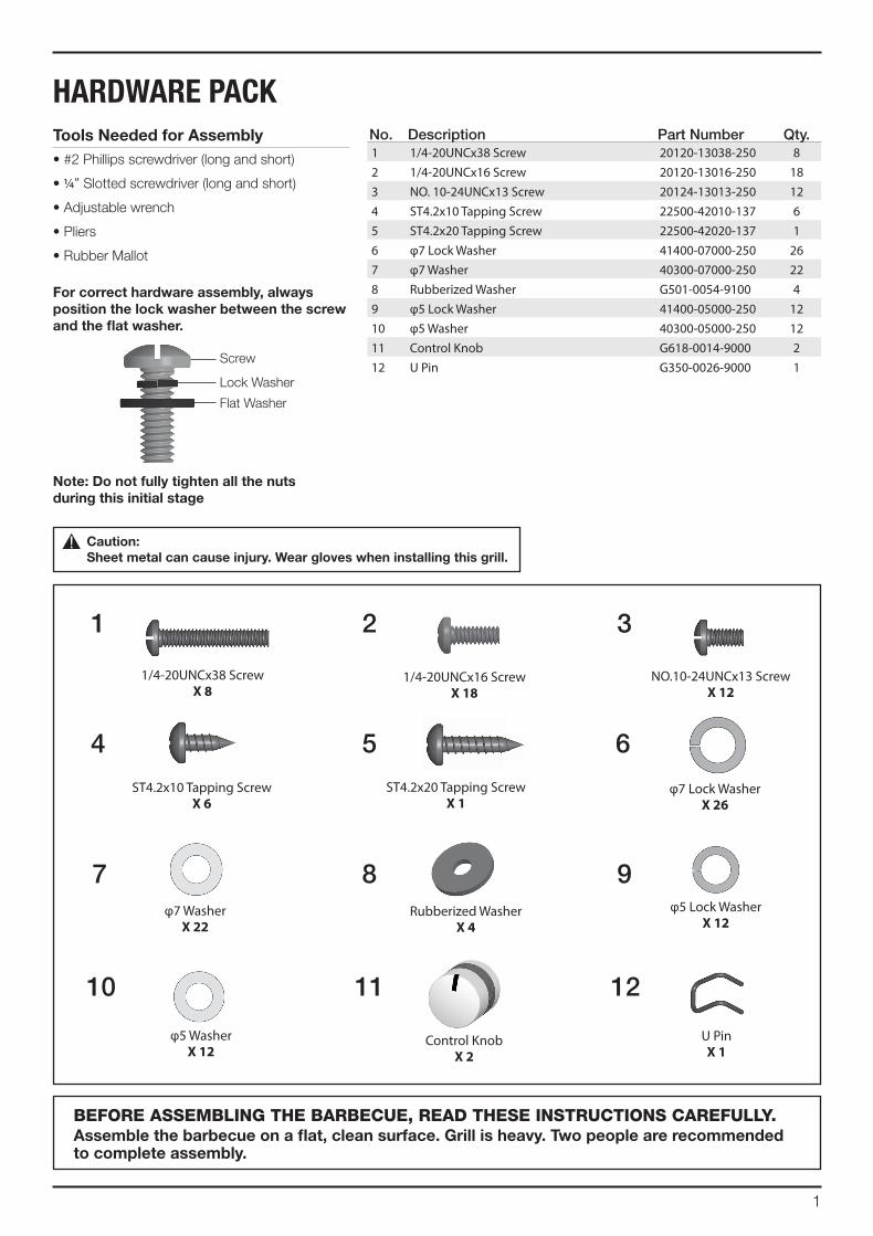
tools Needed for Assembly• #2 Phillips screwdriver (long and short)
• ¼” Slotted screwdriver (long and short)
• Adjustable wrench
• Pliers
• Rubber Mallot
for correct hardware assembly, always position the lock washer between the screw and the flat washer.
Note: do not fully tighten all the nuts during this initial stage
caution: Sheet metal can cause injury. Wear gloves when installing this grill.
BEFORE ASSEMBLING THE BARBECUE, READ THESE INSTRUCTIONS CAREFULLY.Assemble the barbecue on a flat, clean surface. Grill is heavy. two people are recommended to complete assembly.
Lock Washer
Flat Washer
Screw
1 2 3
4 5 6
7 8 9
10 11 12
2
PARTS LIST (PROPANE) FOR 85-3126-2 (G53507)Item No. Qty. Description Part No.
AA 1 Top lid G535-2000-01
AB 1 Lid Handle G535-0002-01
AC 2 Lid Handle End Cap G358-0004-01
AD 1 Thermometer G512-0085-01
AE 2 Screw for Top Lid G359-0030-01
AF 2 Lid Bumper G527-0002-01
AG 1 Logo Plate G618-0054-01
BA1 1 Burner Box Assembly G535-6800-01
BA2 1 Burner Box Surround G535-7100-01
BB 3 Main Burner G525-3800-02
BC 1 Carryover Assembly G535-0033-01
BD 3 3-Pc. Stainless Steel Radiant G618-0056-01
BE 24 Ceramic Stone G535-0045-01
BF 1 Flame Tamer Brace, Front G535-0040-01
BG 1 Flame Tamer Brace, Back G535-0041-01
BH 3 Cooking Grate,Burner Box G535-0044-01
BI 1 Warming Rack G525-0017-01
BJ 1 Infrared Rotisserie Burner G525-2900-01
BK 1 Electrode Set, Rotisserie Burner
G525-0046-01
BL 1 Wind Shield,Rotisserie G525-0047-01
BM 1 Match Holder G501-0068-01
BN 1 IR Rotisserie LP Valve G535-0042-01
BO 1 Lid Support Pin G525-0014-02
CA 1 Manifold Assembly, LP G535-7300-01
CB 1 Regulator G510-0006-01
CC 1 IR Side Burner Valve, LP G535-0023-01
CD 2 Metal Hose G508-0024-01
CE1 1 Rotisserie Flexible Hose G601-0055-A1
CE2 1 Rotisserie LP Orifice G525-0058-01
CF1 1 Electronic Ignition Assembly G535-0032-01
CF2 1 Electronic Ignition Battery Cap G535-0031-02
CG 3 Electrode Set, Main Burner G525-0030-01
CH 5 Control Knob G618-0014-01
CI 5 Bezel, Control Knob G525-0012-01
CJ 1 Control Panel G535-0043-01
CK 1 Front Brace G535-5000-01
CL 1 Grease Tray G350-4400-01
CM 1 Upper Back Panel G535-0013-01
CN 1 Heat Shield G525-0022-01
CO 1 Left Track G515-0024-01
CP 1 Right Track G515-0025-01
CQ 1 Lower Back Panel G535-0012-01
Item No. Qty. Description Part No.
DA 1 Side Shelf Table, Right G535-7600-01
DB 1 Side Shelf Fascia, Right G535-4100-01
DC 1 Infrared Support Frame G535-3500-01
DD 1 Infrared Zone Side Burner G535-8600-01
DE 1 Electrode Set, Infrared Zone G614-0092-01
DF 1 Lid, Infrared Zone G507-0011-01
DG 1 Cooking Grate, Infrared Zone G525-0055-01
DH 1 Infrared Grease Tray G614-0075-01
DI 1 Infrared Side Burner Wind shield
G614-0073-01
DJ 1 Side Shelf Table, Left G535-7800-01
DK 1 Side Shelf Fascia, Left G535-2500-01
EA 1 Cart Side Panel, Left G535-0009-02
EB 1 Cart Side Panel, Right G535-0010-02
EC 1 Bottom Shelf, LP G535-0900-01
ED 2 Wheel with Lock G350-0023-01
EE 2 Wheel G350-0024-01
EF 1 Left Door Assembly G535-2100-01
EG 1 Right Door Assembly G535-2200-01
EH 2 Door Handle G517-0011-01
EI 4 Door Magnet Assembly G501-00F2-03
F1 1 Hardware pack G535-B003-01
F2 1 Assembly Manual G535-M007-01
F3 1 Safety and Care Manual G535-M005-02
F4 1 Tank Screw G505-0047-01
F5 1 Ceramic Heat Plate Guide G618-M003-02
3
BO
COCP
DF
EIEI
BJ
BNCD
CE1CE2
BH
BA1
CJ
AF
AE
BI
AB
AA
CN
DD
BC
EC EB
CI
DG
EG
EA
DK
EH
CG
BB
DJ
CH
AD
AG
BD
BE
BM
BA2
BFBG
AC
AC
CA
CB
CCCD
CF2
CF1
CK
CL
CM
CQ
DA
DB
DE
ED
EE
EF
EH
BK
BL
DC
DH
DI
EXPLODED DIAGRAM (PROPANE) FOR 85-3126-2 (G53507)
Hardware Pack
Tank Screw
Assembly Manual
Safe Use & Care Manual
Ceramic Heat Plate
Guide
EXtRAS
f1 f4f2 f3 f5
4
PARTS LIST (NATURAL GAS) FOR 85-3127-0 (G53508)Item No. Qty. Description Part No.
AA 1 Top lid G535-2000-01
AB 1 Lid Handle G535-0002-01
AC 2 Lid Handle End Cap G358-0004-01
AD 1 Thermometer G512-0085-01
AE 2 Screw for Top Lid G359-0030-01
AF 2 Lid Bumper G527-0002-01
AG 1 Logo Plate G618-0054-01
BA1 1 Burner Box Assembly G535-6800-01
BA2 1 Burner Box Surround G535-7100-01
BB 3 Main Burner G525-3800-02
BC 1 Carryover assembly G535-0033-01
BD 3 3-Pc. Stainless Steel Radiant G618-0056-01
BE 24 Ceramic Stone G535-0045-01
BF 1 Flame Tamer Brace, Front G535-0040-01
BG 1 Flame Tamer Brace, Back G535-0041-01
BH 3 Cooking Grate,Burner Box G535-0044-01
BI 1 Warming Rack G525-0017-01
BJ 1 Infrared Rotisserie Burner G525-2900-01
BK 1 Electrode Set, Rotisserie Burner
G525-0046-01
BL 1 Wind Shield,Rotisserie G525-0047-01
BM 1 Match Holder G501-0068-01
BN 1 IR Rotisserie NG Valve G535-0046-01
BO 1 Lid Support Pin G525-0014-02
CA 1 Manifold Assembly, NG G535-8200-01
CB 1 Natural Gas Hose G501-0099-01
CC 1 IR Side Burner Valve, NG G535-0027-01
CD 2 Metal Hose G508-0024-01
CE1 1 Rotisserie Flexible Hose G601-0055-A1
CE2 1 Rotisserie NG orifice G525-0050-01
CF1 1 Electronic Ignition Assembly G535-0032-01
CF2 1 Electronic Ignition Battery Cap G535-0031-02
CG 3 Electrode Set, Main Burner G525-0030-01
CH 5 Control Knob G618-0014-01
CI 5 Bezel, Control Knob G525-0012-01
CJ 1 Control Panel G535-0043-01
CK 1 Front Brace G535-5000-01
CL 1 Grease Tray G350-4400-01
CM 1 Upper Back Panel G535-0013-01
CN 1 Heat Shield G525-0022-01
CO 1 Left Track G515-0024-01
CP 1 Right Track G515-0025-01
CQ 1 Lower Back Panel G535-0012-01
Item No. Qty. Description Part No.
DA 1 Side Shelf Table, Right G535-7600-01
DB 1 Side Shelf Fascia, Right G535-4100-01
DC 1 Infrared Support Frame G535-3500-01
DD 1 Infrared Zone Side Burner G535-8600-01
DE 1 Electrode Set, Infrared Zone G614-0092-01
DF 1 Lid, Infrared Zone G507-0011-01
DG 1 Cooking Grate, Infrared Zone G525-0055-01
DH 2 Infrared Grease Tray G614-0075-01
DI 1 Infrared Side Burner Wind shield
G614-0073-01
DJ 1 Side Shelf Table, Left G535-7800-01
DK 1 Side Shelf Fascia, Left G535-2500-01
EA 1 Cart Side Panel, Left G535-0009-02
EB 1 Cart Side Panel, Right G535-0010-02
EC 1 Bottom Shelf, NG G535-3400-01
ED 2 Wheel with Lock G350-0023-01
EE 2 Wheel G350-0024-01
EF 1 Left Door Assembly G535-2100-01
EG 1 Right Door Assembly G535-2200-01
EH 2 Door Handle G517-0011-01
EI 4 Door Magnet Assembly G501-00F2-03
F1 1 Hardware pack G535-B003-01
F2 1 Assembly Manual G535-M007-01
F3 1 Safety and Care Manual G535-M005-02
F4 1 Ceramic Heat Plate Guide G618-M003-02
5
BO
COCP
DF
EIEI
BJ
BNCD
CE1CE2
BH
BA1
CJ
AF
AE
BI
AB
AA
CN
DD
BC
EC EB
CI
DG
EG
EA
DK
EH
CG
BB
DJ
CH
AD
AG
BD
BE
BM
BA2
AC
AC
CA
CB
CCCD
CF2
CF1
CK
CL
CM
CQ
DA
DB
DE
ED
EE
EF
EH
BK
BL
DC
DH
DI
BFBG
EXPLODED DIAGRAM (NATURAL GAS) FOR 85-3127-0 (G53508)
Hardware Pack
Assembly Manual
Safe Use & Care Manual
EXtRAS
f1 f2 f3
Ceramic Heat Plate
Guide
f4
6
Separate the 2 different types of wheels, 2 Locking Wheels (ED) and 2 Regular Wheels (EE).
Insert the U Pin (#12) into one of the Regular Wheels (EE), as shown in image B. Attach the Regular Wheel (EE) to the front of the Bottom Shelf (EC), and use the U Pin (#12) to secure and tighten.
Repeat for remaining 3 Wheels (EE & ED).
NotE: Regular Wheels (EE) need to be assembled to the front of the Bottom Shelf (EC), and Wheels with Lock (ED) need to be assembled to the back of the Bottom Shelf (EC), as shown in image A.
6
X 1
YoU WiLL NEEd:
1.
Back view
Close up
EE
EE
12 12
B
A
ASSEMBLY INSTRUCTIONS
Ec
a. Ensure that the wheels are firmly locked in the “ON” position before continuing.
b. Assemble the Left Cart Side Panel (EA) and the Right Cart Side Panel (EB) to the Bottom Shelf (EC).
6
X 6 X 6 X 6
YoU WiLL NEEd:
6 7
2.
Front view
Close up
EB
EB
EA
Ec
Ec
B
A2
Ed
7
ASSEMBLY INSTRUCTIONS
Attach the Front Brace (CK) to the Left and Right Cart Side Panels (EA and EB).
tiP: One person should align the left side, while the second person assembles the right side.
6
X 2 X 2 X 2
YoU WiLL NEEd:
1 6 7
c. Assemble the Lower Back Panel (CQ) to the Left Cart Side Panel (EA) and Right Cart Side Panel (EB).
6
X 4 X 4 X 4
YoU WiLL NEEd:
6 7
3.
2.
Back view
Close up
cK
cQ EAEB
EA
cQ
Ec
EB
A
c
2
cK
EA
B
Close up
cQ EB
d
tiP: The top of the lower back panel (CQ) can be identified by the four recesses located on the top of this part.
tiP: The bottom of the front brace (CK) can be identified by the four recesses located on the bottom of this part.
8
ASSEMBLY INSTRUCTIONS
Back view
Front view
EA
EB
c
cK
b. Assemble Burner Box Assembly (A and B) to the Left and Right Cart Side Panels (EA and EB), as shown.
c. Assemble the front of the Burner Box Assembly (A and B) to the Front Brace (CK), as shown.
Close up - left outside view
tHiS StEP REQUiRES 3 PEoPLE. do Not AttEMPt ALoNE. EXtREMELY HEAvY.
a. Position the Top Lid and Burner Box Assembly (A and B) onto Cart Assembly (C), as shown.
4.
A
c
A+B
Front view
6
X 4 X 4 X 4
YoU WiLL NEEd:
6 72
6
X 2 X 2 X 2
YoU WiLL NEEd:
1 6 7
EB EA
B
A+B
9
ASSEMBLY INSTRUCTIONS
5.
6. a. Open the Lid. Assemble the Left Side Shelf Assembly (DJ and DK) to the Cart Assembly by inserting the Side Shelf Tabs into holes on the Cart Assembly (figure A).
b. Secure using hardware, as shown in figure B, C & D.
Front, left side view
View inside burner box
dJ
dK
A
BA
Attach the Upper Back Panel (CM) to both the Left and Right Cart Side Panels (EA and EB).
Only install hardware in the bottom portion of the Upper Back Panel (CM), as shown in figure B.
do Not tiGHtEN ScREWS UNtiL SidE SHELf HAS BEEN iNStALLEd.
Back view
Close up
EA
cM
EBEA
cM
B
A 6
X 2 X 2 X 2
YoU WiLL NEEd:
1 6 7
6
X 2 X 2 X 2
YoU WiLL NEEd:
6 82
B
dJ
BA
dK
10
ASSEMBLY INSTRUCTIONS
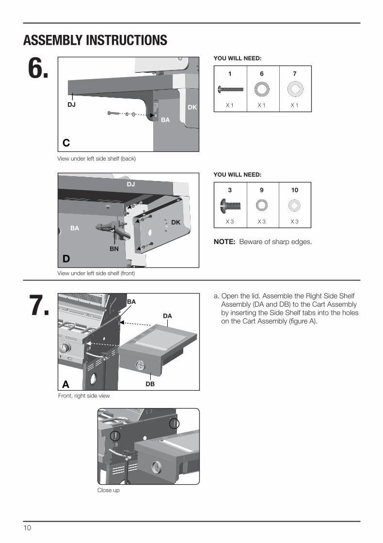
6.
7.
6
X 3 X 3 X 3
YoU WiLL NEEd:
View under left side shelf (back)
View under left side shelf (front)
3 9 10
c
d
dJ
BN
dJ
BAdK
BA
dK
Front, right side view
a. Open the lid. Assemble the Right Side Shelf Assembly (DA and DB) to the Cart Assembly by inserting the Side Shelf tabs into the holes on the Cart Assembly (figure A).
dA
dB
BA
A
Close up
6
X 1 X 1 X 1
YoU WiLL NEEd:
1 6 7
NotE: Beware of sharp edges.
11
ASSEMBLY INSTRUCTIONS
7.
X 3 X 3 X 3
YoU WiLL NEEd:
3 9 10
View under right side shelf (back)
View under right side shelf (front)
BA
dA
c
d
View inside burner box
dA
BA
B
b. Secure using hardware, as shown in figure B, C and D.
dB
X 1 X 1 X 1
YoU WiLL NEEd:
1 6 7
X 2 X 2 X 2
YoU WiLL NEEd:
6 82
dc
BA
dcdB
NotE: Beware of sharp edges.
12
ASSEMBLY INSTRUCTIONS
9.
a. Assemble the Infrared Side Burner Wind Shield (DI) to the Infrared Support Frame (DC), as shown in figure A and B.
di
dc
dc
B
A
6
X 2
YoU WiLL NEEd:
4
di
Front, right side view
Front, right side view
Front, right side view
View from above right side shelf
a. Remove the hardware that is pre-assembled to the Side Burner Valve bracket (CC), as shown in figure A.
b. Insert the Side Burner Valve stem (CC) through the rear of the Right Side Shelf Fascia (DB). Assemble the Side Burner Valve (CC) to the Side Shelf Fascia (DB), using the hardware removed (figure A).
8 . dA
dB
A
B
cc
11
cc
dA
dB6
X 1
YoU WiLL NEEd:
11
c. Assemble the Side Burner Control Knob (#11) to the Side Burner Valve (CC) (figure B).
NotE: Two people recommended.
13
ASSEMBLY INSTRUCTIONS
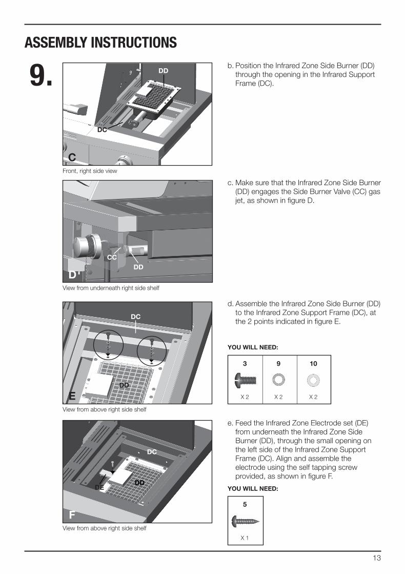
9 . b. Position the Infrared Zone Side Burner (DD) through the opening in the Infrared Support Frame (DC).
c
dd
dc
c. Make sure that the Infrared Zone Side Burner (DD) engages the Side Burner Valve (CC) gas jet, as shown in figure D.
d
ccdd
5
X 1
YoU WiLL NEEd:
d. Assemble the Infrared Zone Side Burner (DD) to the Infrared Zone Support Frame (DC), at the 2 points indicated in figure E.
e. Feed the Infrared Zone Electrode set (DE) from underneath the Infrared Zone Side Burner (DD), through the small opening on the left side of the Infrared Zone Support Frame (DC). Align and assemble the electrode using the self tapping screw provided, as shown in figure F.
E
f
dE
dd
dc
dc
dd
Front, right side view
View from underneath right side shelf
View from above right side shelf
View from above right side shelf
6
X 2 X 2 X 2
YoU WiLL NEEd:
3 9 10
14
ASSEMBLY INSTRUCTIONS
9 .
10.
View under left side shelf
dK
dJ
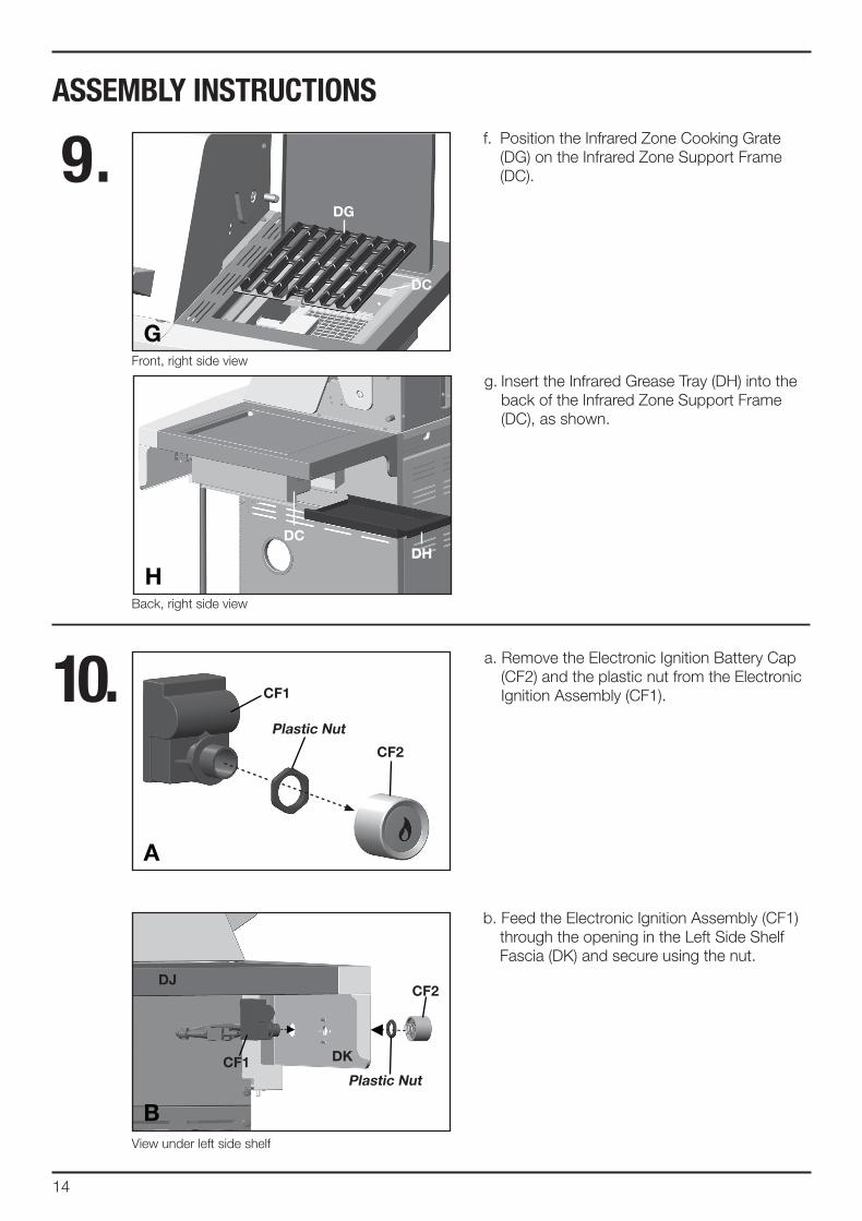
b. Feed the Electronic Ignition Assembly (CF1) through the opening in the Left Side Shelf Fascia (DK) and secure using the nut.
a. Remove the Electronic Ignition Battery Cap (CF2) and the plastic nut from the Electronic Ignition Assembly (CF1).
B
cf1
cf2
f. Position the Infrared Zone Cooking Grate (DG) on the Infrared Zone Support Frame (DC).
G
dG
dc
g. Insert the Infrared Grease Tray (DH) into the back of the Infrared Zone Support Frame (DC), as shown.
H
dcdH
A
cf2
Plastic Nut
cf1
Plastic Nut
Front, right side view
Back, right side view
15
ASSEMBLY INSTRUCTIONS
10.
d
Front, left side view
dK
dJ
c
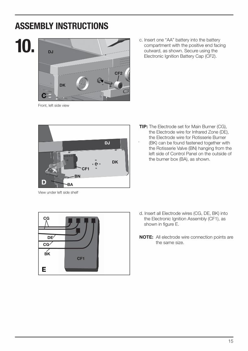
c. Insert one “AA” battery into the battery compartment with the positive end facing outward, as shown. Secure using the Electronic Ignition Battery Cap (CF2).
cf2
+-
d
tiP: The Electrode set for Main Burner (CG), the Electrode wire for Infrared Zone (DE), the Electrode wire for Rotisserie Burner (BK) can be found fastened together with the Rotisserie Valve (BN) hanging from the left side of Control Panel on the outside of the burner box (BA), as shown.
dK
dJ
cf1
BA
d. Insert all Electrode wires (CG, DE, BK) into the Electronic Ignition Assembly (CF1), as shown in figure E.
NotE: All electrode wire connection points are the same size.
View under left side shelf
BN
E
dE
BKcf1
cG
cG
16
Front, left side view
Front, left side view
ASSEMBLY INSTRUCTIONS
11. a. Remove the hardware that is pre-assembled to the Rotisserie Valve bracket (BN), as shown in figure A.
b. Insert the Rotisserie Burner Valve stem (BN) through the rear of the Left Side Shelf Fascia (DK). Assemble the Rotisserie Valve (BL) to the Side Shelf Fascia (DK), using the hardware removed (figure A).
A
B
c. Assemble the Control Knob (#11) to the Rotisserie Valve (BN).
6
X 1
YoU WiLL NEEd:
11
BL
11
BL
dK
dK
17
ASSEMBLY INSTRUCTIONS
12.
Close up, front
cN
cK
6
X 2
YoU WiLL NEEd:
4
b. Assemble the Heat Shield (CN) to the bottom of the Front Brace (CK), as shown in figure B.
Front view
Close up, back
cM
cN
a. Position the Heat Shield (CN) into the two hooks located on the bottom of the Upper Back Panel (CM), as shown in figure A.
Back view
cN
cM
A
cNB
cK
18
13. a. Assemble the Left and Right Tracks (CO and CP) for the Grease Tray (CL), as shown in figure A-C.
b. Both the Left and Right Tracks (CO and CP) should be inserted into the two clips located on the Upper Back Panel (CM), as shown in figure B.
A
B
Front view
EBEA
cK
cPco
cPco cM
Close up, back
ASSEMBLY INSTRUCTIONS
c. Assemble the front of the Left and Right Tracks (CO and CP) to the Front Brace (CK), as shown in figure C.
d. Insert the Grease Tray (CL) into the opening of the Upper Back Panel (CM).
d
6
X 2
YoU WiLL NEEd:
4
c
Back view
Close up, front
cK
cocP
cL cM
19
ASSEMBLY INSTRUCTIONS
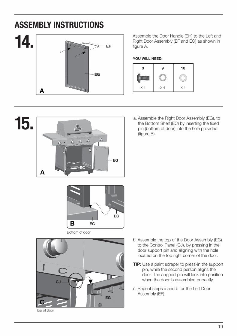
15. a. Assemble the Right Door Assembly (EG), to the Bottom Shelf (EC) by inserting the fixed pin (bottom of door) into the hole provided (figure B).
A
EG
Ec
b. Assemble the top of the Door Assembly (EG) to the Control Panel (CJ), by pressing in the door support pin and aligning with the hole located on the top right corner of the door.
tiP: Use a paint scraper to press-in the support pin, while the second person aligns the door. The support pin will lock into position when the door is assembled correctly.
c. Repeat steps a and b for the Left Door Assembly (EF).
Ec
EG
cJ
EGc
BBottom of door
Top of door
14. Assemble the Door Handle (EH) to the Left and Right Door Assembly (EF and EG) as shown in figure A.
A
EG
EH
6
X 4 X 4 X 4
YoU WiLL NEEd:
3 9 10
20
ASSEMBLY INSTRUCTIONS
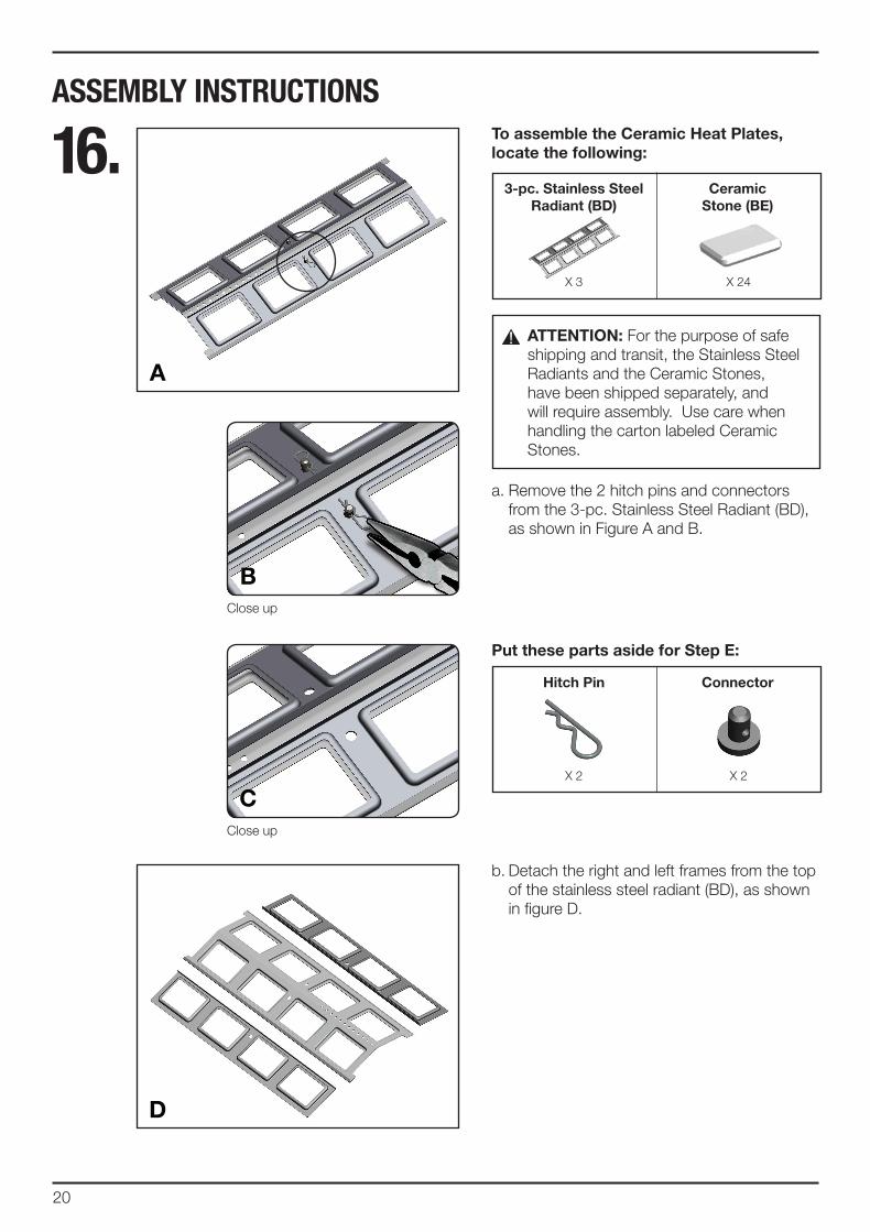
16. to assemble the ceramic Heat Plates, locate the following:
Put these parts aside for Step E:
3-pc. Stainless Steel Radiant (Bd)
Hitch Pin
ceramic Stone (BE)
connector
a. Remove the 2 hitch pins and connectors from the 3-pc. Stainless Steel Radiant (BD), as shown in Figure A and B.
b. Detach the right and left frames from the top of the stainless steel radiant (BD), as shown in figure D.
A
d
Close up
Close up
X 3
X 2
X 24
X 2
B
c
AttENtioN: For the purpose of safe shipping and transit, the Stainless Steel Radiants and the Ceramic Stones, have been shipped separately, and will require assembly. Use care when handling the carton labeled Ceramic Stones.
21
ASSEMBLY INSTRUCTIONS
d. Secure the Ceramic Stones (BE) in place by assembling the right frame back onto the Stainless Steel Radiant (BD), as shown in figure F and G.
E
f
G
16. c. Insert the Ceramic Stones (BE) into the openings on the right side of the Stainless Steel Radiant (BD).
BE
Bd
BEBd
22
ASSEMBLY INSTRUCTIONS
16.You will need these parts from Step A:
Hitch Pinconnector
e. Secure using one set of the connectors and hitch pins, removed in step 20A, as shown in figures H – J.
f. Repeat steps C and D for the left side of the Stainless Steel Radiant (BD) to complete assembly. Figure K shows the assembled Ceramic Heat Plate.
H
i
K
Close up
X 1X 1
Bd
BE
J
23
ASSEMBLY INSTRUCTIONS
L
M
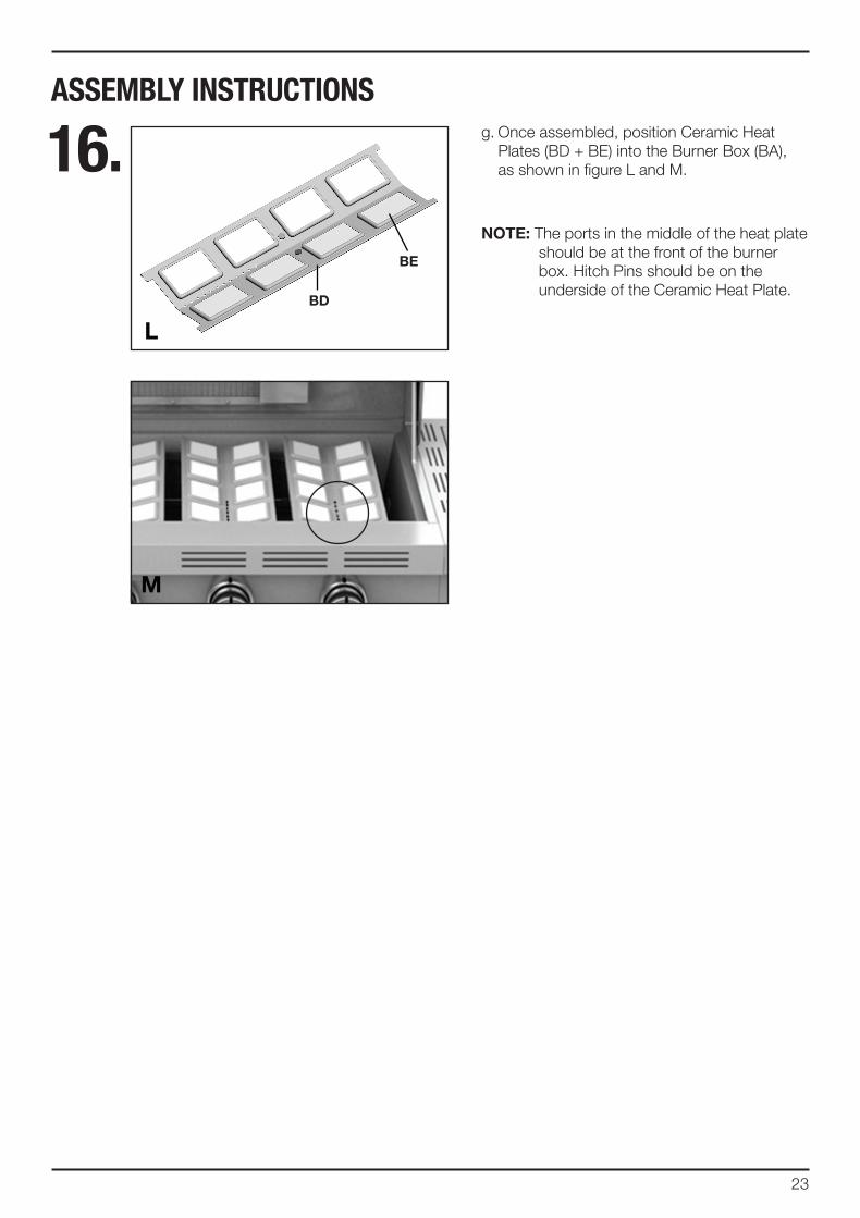
16. g. Once assembled, position Ceramic Heat Plates (BD + BE) into the Burner Box (BA), as shown in figure L and M.
NotE: The ports in the middle of the heat plate should be at the front of the burner box. Hitch Pins should be on the underside of the Ceramic Heat Plate.
BE
Bd
24
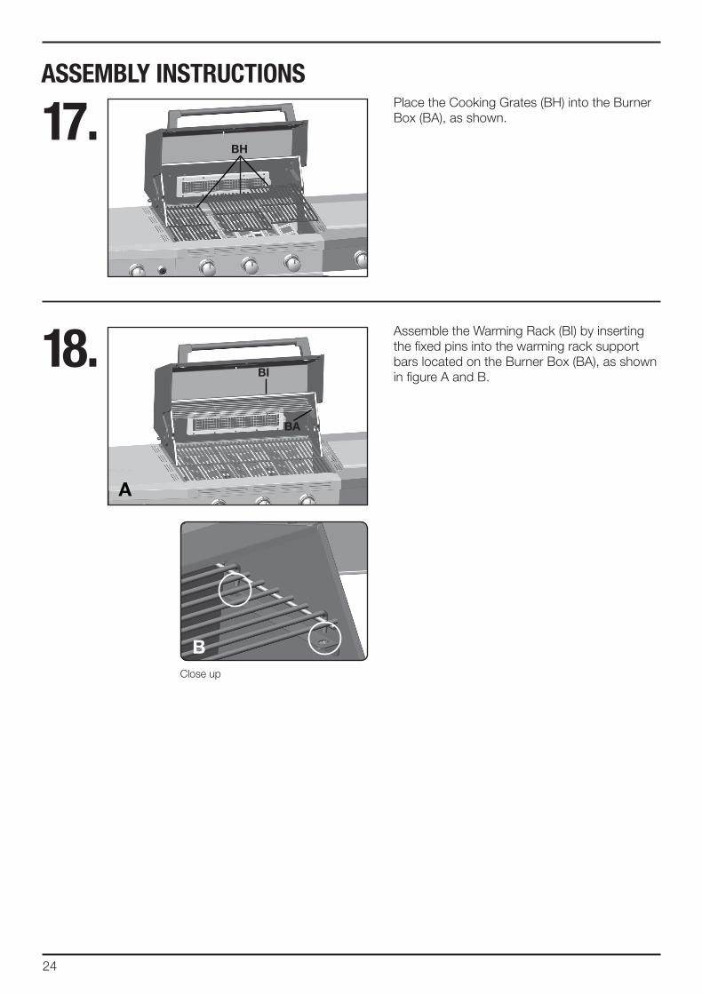
ASSEMBLY INSTRUCTIONSPlace the Cooking Grates (BH) into the Burner Box (BA), as shown.17.
18.
BH
Assemble the Warming Rack (BI) by inserting the fixed pins into the warming rack support bars located on the Burner Box (BA), as shown in figure A and B.Bi
BA
Close up
A
B
25
ASSEMBLY INSTRUCTIONS
AttENtioN: For your families safety, do not attempt to light this BBQ until you have reviewed pages 4-7 of the Cuisinart® Safety & Care Manual. All Safety and Leak test MUSt BE PERfoRMEd BY tHE ENd USER, prior to lighting this BBQ.
WARNiNG do not store extra propane tanks within BBQ cart.
foR PRoPANE ModELS oNLY.
for natural gas model, follow step 20.
a. Position the Regulator Hose (CB) through the hole in the Right Side Panel (EB).
b. Attach the regulator coupling nut to the LP cylinder valve. Be careful not to cross thread. Hand tighten only.
c. Position the 20 lb propane tank onto the Bottom Shelf (EC), and secure using the Bolt (F4) (already attached) located on the underside of the Bottom Shelf, as shown in figure C.
d. Perform Leak Test. See page 5 of the Cuisinart® Safety and Care Manual.
cB
cB
f4
Ec
A
B
c
EB
19.
26
ASSEMBLY INSTRUCTIONS
AttENtioN: For your families safety, do not attempt to light this BBQ until you have reviewed pages 4-7 of the Cuisinart® Safety & Care Manual. All Safety and Leak test MUSt BE PERfoRMEd BY tHE ENd USER, prior to lighting this BBQ.
WARNiNG: For all new, at home,natural gas connections pleasecontact a certified gas technician toinstall your natural gas barbecue.
foR NAtURAL GAS ModEL oNLY.
a. Attach the Natural Gas Hose (CB) to the Side Burner Valve (CC) as shown.
b. Perform Leak Test. See page 6 of the Cuisinart® Safety and Care Manual.
20 .
AttENtioN: In order to complete installation of your Natural Gas BBQ a 1/2” or 3/8” adapter may be required to connect your BBQ’s Natural Gas hose to your home gas supply. Contact your Natural Gas supplier to purchase the necessary part.
cB
cBNatural Gas
Home Supply
Quick connector
cc
A
B
• cAUtioN!
• Avoid BURNS!
• do Not toUcH WHEN BBQ iS iN USE!
• EXtREMELY Hot SURfAcE!
* SHAdEd AREAS BEcoME EXtREMELY Hot WHEN iN USE.
WARNING HOT SURFACES
!!
!
visit www.cuisinartbbqs.com to complete product registration.
Cuisinart® is a registered trademark used under license