36
2807930 User’s Manual Version 1.0 ATX Industrial Motherboard

2807930 User’s Manual
Version 1.0 ATX Industrial Motherboard

Copyrights This document is copyrighted and all rights are reserved. It does not allow any non authorization in copied, photocopied, translated or reproduced to any electronic or machine readable form in whole or in part without prior written consent from the manufacturer. In general, the manufacturer will not be liable for any direct, indirect, special, incidental or consequential damages arising from the use of inability to use the product or documentation, even if advised of the possibility of such damages. The manufacturer keeps the rights in the subject to change the contents of this document without prior notices in order to improve the function design, performance, quality and reliability. The author assumes no responsibility for any errors or omissions, which may appear in this document, nor does it make a commitment to update the information contained herein. Trademarks Intel is a registered trademark of Intel Corporation. Award is a registered trademark of Award Software, Inc. All other trademarks, products and or product's name mentioned herein are mentioned for identification purposes only, and may be trademarks and/or registered trademarks of their respective companies or owners.

- i -
Table of ContentsChapter 1 - Introduction ............................................1
1.1 Copyright Notice ...................................................21.2 About this User’s Manual .....................................21.3 Warning..................................................................21.4 Replacing the lithium battery ..............................31.5 Technical Support .................................................31.6 Warranty ................................................................41.7 Packing List ...........................................................51.8 Ordering Information ............................................51.9 Specification .........................................................61.10 Board Dimensions ..............................................71.11 Installing the CPU ...............................................81.12 Installing the Memory .........................................9
Chapter 2 - Installation ............................................ 112.1 Block Diagram .....................................................122.2 Jumpers and Connectors ..................................13Jumpers ......................................................................14
JP3: PATA IDE Select ............................................14JBAT1: CMOS Setup .............................................14JRS1: COM2 RS-232/422/485 Mode Select ..........15JP2: AT/ATX Power Mode Select ..........................16JP1: BIOS Write Protect ........................................16
Connectors .................................................................17SATA1 ~4: Serial ATA Connectors ........................17IDE1: Primary IDE Connector ...............................18TPM1: Trusted Platform Module Connector ........19USB1 ~3: USB Connectors ...................................19JFRT1: Switches and Indicators ..........................20COM2: RS-232/422/485 Connector .......................21FDD1: FDD Connector ...........................................21DIO1: Digital I/O Connector ..................................22CDIN1: Audio CD IN Connector ............................22
- ii -
LOUT1: Audio Line Out Connector ......................22ATX1: ATX Power Supply Connector ...................23ATX12V1: ATX +12V Connector ............................23EKB1: External Keyboard/ Mouse Connector.....24SYSF1/SYSF2: System Fan Power Connectors..24CPUF1: CPU Fan Power Connector .....................24Audio1/ Audio2: HD Audio Phone Jacks .............25LAN1/LAN2: RJ-45 & double stack USB Connectors.......................................25VGA1: CRT Connector ..........................................26COM1: RS-232 Connector .....................................26LPT1: Parallel Port Connector..............................27KBM1: PS/2 Keyboard & Mouse Connectors ......27
2.3 The Installation Paths of CD Driver ...................28

- � -
1Chapter 1
Introduction
Chapter 1 - Introduction

- 2 -
1.2 About this User’s ManualThis User’s Manual is intended for experienced users and integrators with hardware knowledge of personal computers. If you are not sure about any description in this User’s Manual, please consult your vendor before further handling.
1.3 WarningSingle Board Computers and their components contain very delicate Integrated Circuits (IC). To protect the Single Board Computer and its components against damage from static electricity, you should always follow the following precautions when handling it : �. Disconnect your Single Board Computer from the power source when you
want to work on the inside.2. Hold the board by the edges and try not to touch the IC chips, leads or
circuitry.3. Use a grounded wrist strap when handling computer components.4. Place components on a grounded antistatic pad or on the bag that came
with the Single Board Computer, whenever components are separated from the system.

- 3 -
1.4 Replacing the lithium batteryIncorrect replacement of the lithium battery may lead to a risk of explosion. The lithium battery must be replaced with an identical battery or a battery type recommended by the manufacturer.Do not throw lithium batteries into the trashcan. It must be disposed of in accordance with local regulations concerning special waste.

- 4 -
1.6 WarrantyThis product is warranted to be in good working order for a period of two years from the date of purchase. Should this product fail to be in good working order at any time during this period, we will, at our option, replace or repair it at no additional charge except as set forth in the following terms. This warranty does not apply to products damaged by misuse, modifications, accident or disaster.Vendor assumes no liability for any damages, lost profits, lost savings or any other incidental or consequential damage resulting from the use, misuse of, or inability to use this product. Vendor will not be liable for any claim made by any other related party.Vendors disclaim all other warranties, either expressed or implied, including but not limited to implied warranties of merchantibility and fitness for a particular purpose, with respect to the hardware, the accompanying product’s manual(s) and written materials, and any accompanying hardware. This limited warranty gives you specific legal rights.Return authorization must be obtained from the vendor before returned merchandise will be accepted. Authorization can be obtained by calling or faxing the vendor and requesting a Return Merchandise Authorization (RMA) number. Returned goods should always be accompanied by a clear problem description.

- � -
1.7 Packing List
If any of the above items is damaged or missing, contact your vendor immediately.
� x 2807930 ATX Industrial Motherboard
� x Driver CD
� x Quick Installation Guide
COM Port Cable x �IDE Cable x �USB Cable x �SATA Cable x 2
- 6 -
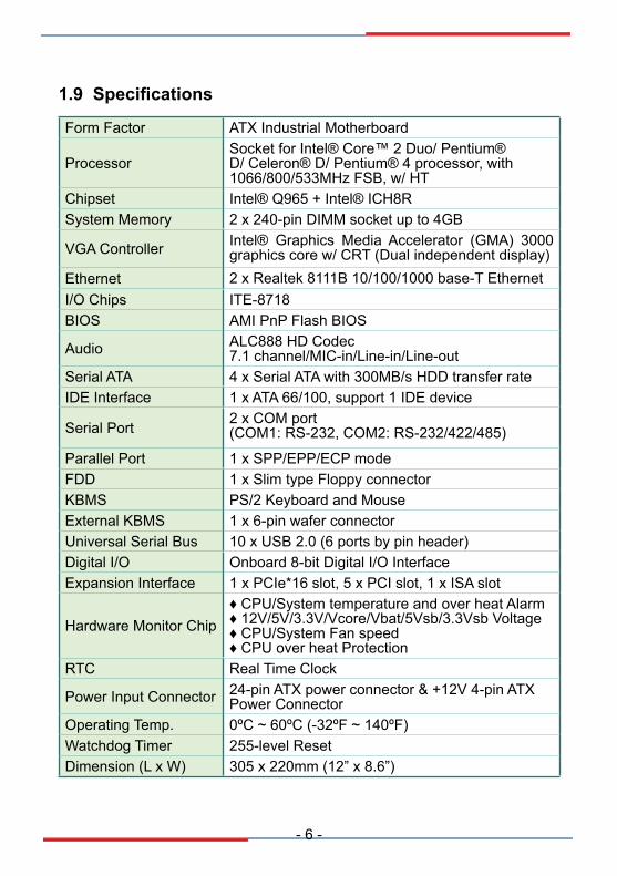
1.9 Specifications
Form Factor ATX Industrial Motherboard
ProcessorSocket for Intel® Core™ 2 Duo/ Pentium® D/ Celeron® D/ Pentium® 4 processor, with �066/800/�33MHz FSB, w/ HT
Chipset Intel® Q96� + Intel® ICH8RSystem Memory 2 x 240-pin DIMM socket up to 4GB
VGA Controller Intel® Graphics Media Accelerator (GMA) 3000 graphics core w/ CRT (Dual independent display)
Ethernet 2 x Realtek 8���B �0/�00/�000 base-T EthernetI/O Chips ITE-87�8BIOS AMI PnP Flash BIOS
Audio ALC888 HD Codec7.� channel/MIC-in/Line-in/Line-out
Serial ATA 4 x Serial ATA with 300MB/s HDD transfer rateIDE Interface � x ATA 66/�00, support � IDE device
Serial Port 2 x COM port(COM�: RS-232, COM2: RS-232/422/48�)
Parallel Port � x SPP/EPP/ECP modeFDD � x Slim type Floppy connectorKBMS PS/2 Keyboard and MouseExternal KBMS � x 6-pin wafer connectorUniversal Serial Bus �0 x USB 2.0 (6 ports by pin header)Digital I/O Onboard 8-bit Digital I/O InterfaceExpansion Interface � x PCIe*�6 slot, � x PCI slot, � x ISA slot
Hardware Monitor Chip♦ CPU/System temperature and over heat Alarm ♦ �2V/�V/3.3V/Vcore/Vbat/�Vsb/3.3Vsb Voltage♦ CPU/System Fan speed ♦ CPU over heat Protection
RTC Real Time Clock
Power Input Connector 24-pin ATX power connector & +�2V 4-pin ATX Power Connector
Operating Temp. 0ºC ~ 60ºC (-32ºF ~ �40ºF)Watchdog Timer 2��-level ResetDimension (L x W) 30� x 220mm (�2” x 8.6”)

- 7 -
1.10 Board Dimensions
Unit : mm
78.7445.72 16.51
304.8
157.48
14.9914.3517.5320.5726.4218.0318.0323.37
41.28
33.02
132.0
8
16.51124.46157.48
10.16
219.9
6
7-ø4.00
Mouse
KeyboardUSB1
USB2
USB3
USB4
Parallel Port
COM1 Port VGA

- 8 -
1.11 Installing the CPUThe LGA77� processor socket comes with a lever to secure the processor. Please refer to the pictures step by step as below. Please note that the cover of the LGA77� socket must always be installed during transport to avoid damage to the socket.
Make sure that heat sink of the CPU top surface is in complete contact to avoid the CPU overheating problem.If not, it would cause your system or CPU to be hanged, unstable, damaged.
� 2 3
6�4
7 8 9

- 9 -
1.12 Installing the MemoryTo install the Memory module, locate the Memory DIMM slot on the board and perform as below:�. Hold the Memory module so that the key of the Memory module align
with those on the Memory DIMM slot.2. Gently push the Memory module in an upright position and a right way
until the clips of the DIMM slot close to lock the Memory module in place, when the Memory module touches the bottom of the DIMM slot.
3. To remove the Memory module, just pressing the clips of DIMM slot with both hands.
Lock Lock

- �0 -
This page is intentionally left blank.
- �� -
2Chapter 2
Installation
Chapter 2 - Installation

- �2 -
2.1 Block Diagram
2 x 240pin DDRII DIMM socket
Intel®Q965
LGA775CPU SocketFor Intel®
CPU
5 x PCI
PCI-to-ISABridge
1 x ISA
PCI LAN Controller
2 x LANRJ-45
1 x slot PCIe x 16
FSB 533/800MHz
Analog R.G.B.
DMI
USB I/F
Serial ATA I/F
Intel®ICH8R
Super IO
COM1COM2
LPT1FDD IrDAKB
MS DIO
1 x IDE
10 x USB
4 x SATA
HD Audio
1 x TPM1.2
VGA DDRII
PCIe x 16
ISA Bus
CodecHD
LPC I/F
PATAController
PCI Bus

- �3 -
2.2 Jumpers and Connectors
25
24
23
22
16
29
27
2826
18 17
19
1
2
3
4
789
10 5
6
DIMM1 DIMM2
LGA775 socket
SYSF2SYSF1CPUF1
ATX12V1EKBM1
KBM1
SATA3SATA4
SATA1SATA2
USB5USB3USB4
TPM1
IDE1JFRT1
JBAT1
JP3
JP2
FDD1
DIO1
JRS1
JP1
CDIN1
AUDIO1
AUDIO2
LAN1
COM1
LPT1
LAN2
VGA1
LOUT1
COM2
ATX1
15 14
34
13
12
11
2021
33
32
31
30

- �4 -
JumpersJP3: PATA IDE Select (30)Connector type: 2.�4mm pitch �x2 pin header.Pin 1-2 Function Select
Short Disable 1 2
Open Enable (Default) 1 2
JBAT1: CMOS Setup (31)If the board refuses to boot due to inappropriate CMOS settings here is how to proceed to clear (reset) the CMOS to its default values.Connector type: 2.�4mm pitch �x3 pin headerPin Mode
�-2 Keep CMOS (Default)23 1
2-3 Clear CMOS23 1
You may need to clear the CMOS if your system cannot boot up because you forgot your password, the CPU clock setup is incorrect, or the CMOS settings need to be reset to default values after the system BIOS has been updated.Refer to the following solutions to reset your CMOS setting:Solution A:�. Power off the system and disconnect the power cable.2. Place a shunt to short pin 1 and pin 2 of JBAT1 for five seconds.3. Place the shunt back to pin 2 and pin 3 of JBAT�.4. Power on the system.Solution B:If the CPU Clock setup is incorrect, you may not be able to boot up. In this case, follow these instructions:�. Turn the system off, then on again. The CPU will automatically boot up using standard parameters.2. As the system boots, enter BIOS and set up the CPU clock.Note:If you are unable to enter BIOS setup, turn the system on and off a few times.

- �� -
JRS1: COM2 RS-232/RS-422/RS-485 Mode Select (32)Connector type: 2.00 mm pitch 2x7 pin header
Mode RS-232(Default) RS-422 RS-485
�-2 Off On On3-4 Off On On�-6 Off Off On7-8 Off On Off9-�0 Off On On��-�2 On Off Off�3-�4 Off Off On
1 2
13 14
1 2
13 14
1 2
13 14

- �6 -
JP2: AT/ATX Power Mode Select (33)The power mode jumper selects the power mode for the system.Connector type: 2.�4mm pitch �x2 pin header.Pin 1-2 Mode
Short AT Mode 1 2
Open ATX Mode (Default) 1 2
JP1: BIOS Write protect (34)Connector type: 2.�4mm pitch �x3 pin header.Pin Mode
�-2 Write protect (default)23 1
2-3 Write Enable23 1

- �7 -
Connectors
SATA1~4: Serial ATA Connectors (1), (2), (3), (4)There are on board supports four SATA II connectors, second generation SATA drives transfer data at speeds as high as 300MB/s, twice the transfer speed of first generation SATA drives. The SATA drives can be configured in a RAID 0, RAID 1 or RAID 10 configuration.Pin Description� GND2 TX+3 TX-4 GND� RX-6 RX+ 7 GND

- �8 -
IDE1: Primary IDE Connector (5)An IDE drive ribbon cable has two connectors to support two IDE devices. If a ribbon cable connects to two IDE drives at the same time, one of them has to be configured as Master and the other has to be configured as Slave by setting the drive select jumpers on the drive.Consult the documentation that came with your IDE drive for details on jumper locations and settings. You must orient the cable connector so that the pin � (color) edge of the cable corresponds to pin � of the IDE connector.Connector type: 2.�4mm pitch 2x20 box headerPin Description Pin Description� IDE RESET 2 GND3 DATA7 4 DATA8� DATA6 6 DATA97 DATA� 8 DATA�09 DATA4 �0 DATA���� DATA3 �2 DATA�2�3 DATA2 �4 DATA�3�� DATA� �6 DATA�4�7 DATA0 �8 DATA���9 GND 20 N/C (Key)2� REQ 22 GND23 IO WRITE 24 GND2� IO READ 26 GND27 IO READY 28 IDESEL29 DACK 30 GND3� IRQ�4 32 N/C33 ADDR� 34 ATA66 DETECT3� ADDR0 36 ADDR237 CS0# 38 CS�# (HDSELET�)39 IDEACTP 40 GND

- �9 -
TPM1: Trusted Platform Module Connector (6)The TPM connector is interfaced to the Intel ICH9 south bridge through the LPC bus. The ICH9 supports TPM version �.2 devices for enhanced security.Connector type: 2.�4mm pitch 2x�0 pin headerPin Description Pin Description� CLK 2 GND3 LFRAME 4 N/C� LRESET 6 N/C7 LAD3 8 LAD29 +3.3V �0 LAD��� LAD0 �2 GND�3 N/C �4 N/C�� +3.3V_SB �6 SERIRQ�7 GND �8 CLKRUN�9 PD 20 N/C
USB1/ USB2/ USB3: USB Connectors (7), (8), (9)On board supports three headers USB�, USB2, and USB3 that can connect up to six high-speed (Data transfers at 480MB/s), full-speed (Data transfers at �2MB/s) or low-speed (Data transfers at �.�MB/s) USB devices.Connector type: 2.�4mm 2x� pin headerPin Description Pin Description
1 2
109
� +�V 2 +�V3 USBD- 4 USBD-� USBD+ 6 USBD+7 GND 8 GND9 N/C (Key) �0 N/C

- 20 -
JFRT1: Switches and Indicators (10)It provides connectors for system indicators that provides light indicationof the computer activities and switches to change the computer status.Connector type: 2.�4mm pitch 2x�3 pin headerPin Description Pin Description� +�V 2 RESET+3 N/C 4 RESET-� IRRX 6 N/C7 GND 8 SPKR9 IRTX �0 BUZZ�� N/C �2 GND�3 HDD_LED+ �4 +�V�� HDD_LED- �6 N/C�7 TB_LED+ �8 POWER_LED+�9 TB_LED- 20 N/C2� N/C 22 POWER_LED-23 PWRBTN+ 24 KBLOCK2� PWRBTN- 26 GND
IrDA: Infrared connector, pin �, 3, �, 7, 9
HLED: HDD LED Connector, pin �3-��.This 2-pin connector connects to the case-mounted HDD LED to indicate hard disk activity.
RES: Reset Button, pin 2-4.This 2-pin connector connects to the case-mounted reset switch and is used to reboot the system.
TB_LED: pin �7-�9
PWRBTN: ATX soft power switch, pin 23-2�.This 2-pin connector connects to the case-mounted Power button.
PLED: Power LED Connector, pin �8, 20, 22.This 3-pin connector connects to the case-mounted power LED. Power LED can be indicated when the CPU card is on or off. And keyboard lock can be used to disable the keyboard function so the PC will not respond by any input.
SPK: External Speaker, pin 8, �0, �2, �4.This 4-pin connector connects to the case-mounted speaker.
KBLOCK: Keyboard Lock, pin 24-26.
- 2� -
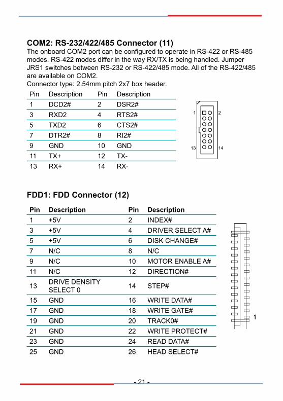
COM2: RS-232/422/485 Connector (11)The onboard COM2 port can be configured to operate in RS-422 or RS-485 modes. RS-422 modes differ in the way RX/TX is being handled. Jumper JRS� switches between RS-232 or RS-422/48� mode. All of the RS-422/48� are available on COM2.Connector type: 2.�4mm pitch 2x7 box header.Pin Description Pin Description� DCD2# 2 DSR2#3 RXD2 4 RTS2#� TXD2 6 CTS2#7 DTR2# 8 RI2#9 GND �0 GND�� TX+ �2 TX-�3 RX+ �4 RX-
FDD1: FDD Connector (12)
Pin Description Pin Description� +�V 2 INDEX#3 +�V 4 DRIVER SELECT A#� +�V 6 DISK CHANGE#7 N/C 8 N/C9 N/C �0 MOTOR ENABLE A#�� N/C �2 DIRECTION#
�3 DRIVE DENSITY SELECT 0 �4 STEP#
�� GND �6 WRITE DATA#�7 GND �8 WRITE GATE#�9 GND 20 TRACK0#2� GND 22 WRITE PROTECT#23 GND 24 READ DATA#2� GND 26 HEAD SELECT#
- 22 -
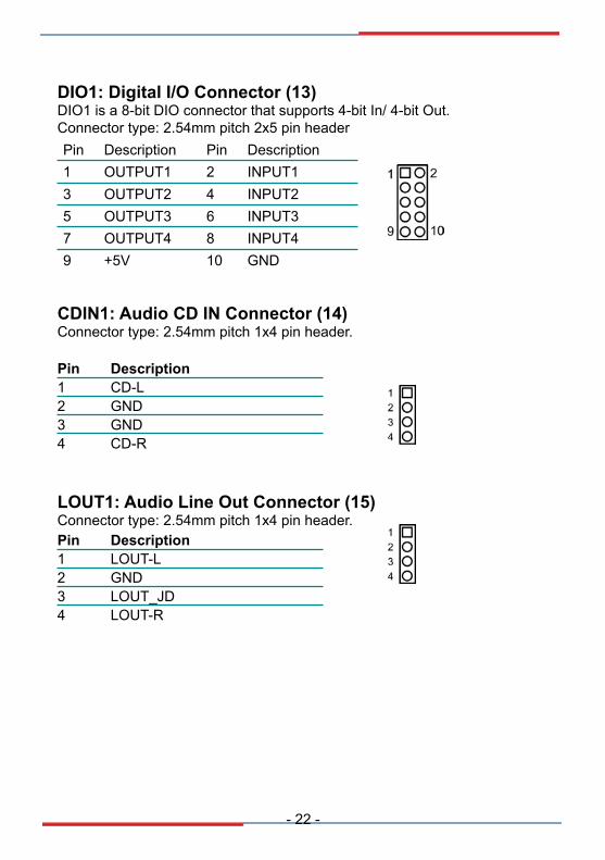
CDIN1: Audio CD IN Connector (14)Connector type: 2.�4mm pitch �x4 pin header.
Pin Description� CD-L2 GND3 GND4 CD-R
LOUT1: Audio Line Out Connector (15)Connector type: 2.�4mm pitch �x4 pin header.Pin Description� LOUT-L2 GND3 LOUT_JD4 LOUT-R
DIO1: Digital I/O Connector (13)DIO� is a 8-bit DIO connector that supports 4-bit In/ 4-bit Out.Connector type: 2.�4mm pitch 2x� pin headerPin Description Pin Description� OUTPUT� 2 INPUT�3 OUTPUT2 4 INPUT2� OUTPUT3 6 INPUT37 OUTPUT4 8 INPUT49 +�V �0 GND

- 23 -
ATX1: ATX Power Supply Connector (16)The ATX power supply has a single lead connector with a clip on one side of the plastic housing. There is only one way to plug the lead into the ATX power connector. Press the lead connector down until the clip snaps into place and secures the lead onto the connector.Pin Description Pin Description
113
1224
�3 +3.3V � +3.3V
�4 -�2V 2 +3.3V
�� GND 3 GND
�6 PS-ON 4 +�V
�7 GND � GND
�8 GND 6 +�V
�9 GND 7 GND
20 -�V 8 PW-OK
2� +�V 9 +�VSB
22 +�V �0 +�2V
23 +�V �� +�2V
24 GND �2 +3.3VWarningIncorrect installation of the power supply could result in serious damage to the mainboard and connected peripherals. Make sure the power supply is unplugged from the AC outlet before connecting the leads from the power supply.
2
4
1
3
ATX12V1: ATX +12V Connector (17)
Pin Description Pin Description2 GND � GND4 +�2V 3 +�2V
ATX�2V� supplies the CPU operation ATX +�2V (Vcore).

- 24 -
CPUF1: CPU Fan Power Connector (21)CPUF� is a 4-pin header for the CPU fan. The fan must be a +�2V fan.
Pin Description� GND2 +�2V3 Fan_ Detect4 Fan Speed Control
SYSF1/SYSF2: System Fan Power Connectors (19), (20)
SYSF� and SYSF2 are 3-pin header for the system fan. The fan must be a +�2V fan.
Pin Description� GND2 +�2V3 FAN_Detect
EKBM1: External keyboard and Mouse Connector (18)Connector type: 2.�0mm pitch �x6-pin box wafer connectorPin Description
123456
� KB_Data2 GND3 MS_Data4 KB_Clock� +�V6 MS_Clock

- 2� -
Audio1/ Audio2: HD Audio Phone Jacks (22), (23)
LAN�/ LAN2 each one supports one �0/�00/�000 Mbps fast Ethernet and two USB 2.0 connectors w/ 480MB/s.
LAN1/LAN2: RJ-45 & double stack USB Connectors (24), (25)
�0/�00/�000 RJ-4�
USB3
USB4
�0/�00/�00 RJ-4�
USB�
USB2
Line In
Line Out
MIC In
CEN/LFE
Surr_Out
SIDE_Out
- 26 -
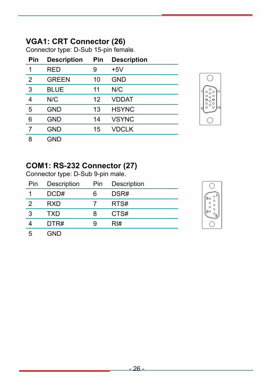
VGA1: CRT Connector (26)Connector type: D-Sub ��-pin female.Pin Description Pin Description
1
5 15
11
� RED 9 +�V2 GREEN �0 GND3 BLUE �� N/C4 N/C �2 VDDAT� GND �3 HSYNC6 GND �4 VSYNC7 GND �� VDCLK8 GND
COM1: RS-232 Connector (27)Connector type: D-Sub 9-pin male.Pin Description Pin Description
1
59
6� DCD# 6 DSR#2 RXD 7 RTS#3 TXD 8 CTS#4 DTR# 9 RI#� GND

- 27 -
LPT1: Parallel Port Connector (28)Connector type: D-Sub 2�-pin female.Pin Description Pin Description
1
13
14
25
� STROBE �4 AFD2 PTD0 �� ERROR3 PTD� �6 INIT4 PTD2 �7 SLIN� PTD3 �8 GND6 PTD4 �9 GND7 PTD� 20 GND8 PTD6 2� GND9 PTD7 22 GND�0 ACK 23 GND�� BUSY 24 GND�2 PE 2� GND�3 SELECT 26 N/C
KBM1: PS/2 Keyboard & Mouse (29)Standard Mini-DIN PS/2 Keyboard & Mouse connectorPin Description
78
9
1112
10
Keyboard(Purple)
12
3
56
4
Mouse(Green)
� KB Data2 N/C3 GND4 +�V� KB Clock6 N/C7 MS Data8 N/C9 GND�0 +�V�� MS Clock�2 N/C
- 28 -
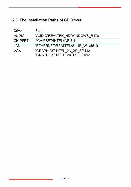
2.3 The Installation Paths of CD Driver
Driver PathAUDIO \AUDIO\REALTEK_HD\WINDOWS_R�78CHIPSET \CHIPSET\INTEL\INF 8.�LAN \ETHERNET\REALTEK\8���B_WIN�640VGA \GRAPHICS\INTEL_2K_XP_32\�43�
\GRAPHICS\INTEL_VISTA_32\��6�
Chapter 3
Appendix
Chapter 4 - Appendix
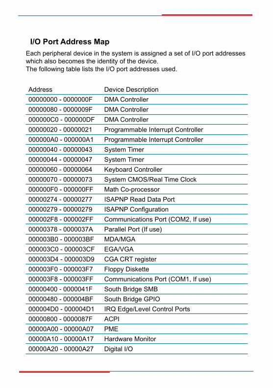
Each peripheral device in the system is assigned a set of I/O port addresses which also becomes the identity of the device.The following table lists the I/O port addresses used.
I/O Port Address Map
Address Device Description00000000 - 0000000F DMA Controller00000080 - 0000009F DMA Controller000000C0 - 000000DF DMA Controller00000020 - 0000002� Programmable Interrupt Controller000000A0 - 000000A� Programmable Interrupt Controller00000040 - 00000043 System Timer00000044 - 00000047 System Timer00000060 - 00000064 Keyboard Controller00000070 - 00000073 System CMOS/Real Time Clock000000F0 - 000000FF Math Co-processor00000274 - 00000277 ISAPNP Read Data Port00000279 - 00000279 ISAPNP Configuration000002F8 - 000002FF Communications Port (COM2, If use)00000378 - 0000037A Parallel Port (If use)000003B0 - 000003BF MDA/MGA000003C0 - 000003CF EGA/VGA000003D4 - 000003D9 CGA CRT register000003F0 - 000003F7 Floppy Diskette000003F8 - 000003FF Communications Port (COM�, If use)00000400 - 000004�F South Bridge SMB00000480 - 000004BF South Bridge GPIO000004D0 - 000004D� IRQ Edge/Level Control Ports00000800 - 0000087F ACPI00000A00 - 00000A07 PME00000A�0 - 00000A�7 Hardware Monitor00000A20 - 00000A27 Digital I/O

00000A30 - 00000A37 SFIF00000CF8 PCI Configuration Address00000CFC PCI Configuration Data00004700 - 0000470B TPM (If use)
Peripheral devices use interrupt request lines to notify CPU for the service required. The following table shows the IRQ used by the devices on board.
Interrupt Request Lines (IRQ)
Level FunctionIRQ 0 System TimerIRQ � Keyboard ControllerIRQ 2 VGA and Link to Secondary PICIRQ 3 Communications Port (COM2)IRQ 4 Communications Port (COM�)IRQ � PCI DeviceIRQ 6 Standard Floppy Disk ControllerIRQ 7 Parallel PortIRQ 8 System CMOS/real time clockIRQ 9 Microsoft ACPI-Compliant SystemIRQ �0 PCI DeviceIRQ �� PCI DeviceIRQ �2 PS/2 Compatible MouseIRQ �3 FPU ExceptionIRQ �4 PCI DeviceIRQ �� PCI Device

Address Device Description00000h - 9FFFFh DOS Kernel AreaA0000h, BFFFFh EGA and VGA Video Buffer (�28KB)C00000h - CFFFFh EGA/VGA ROMD0000h - DFFFFh Adaptor ROME00000h - FFFFFh System BIOSEFD40000h - FED44FFFFh TPM (If use)
BIOS memory mapping


