64
INSTALLER MANUAL IHB EN 1918-8 231758 Control module NIBE SMO 20
INSTALLER MANUALIHB EN 1918-8231758
Control module NIBE SMO 20
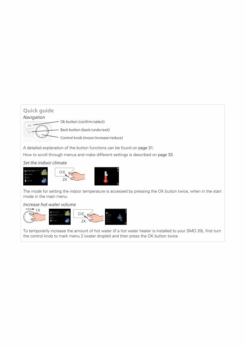
Quick guideNavigation
Ok button (confirm/select)
Back button (back/undo/exit)
Control knob (move/increase/reduce)
A detailed explanation of the button functions can be found on page 31.
How to scroll through menus and make different settings is described on page 33.
temperature1.1
Set the indoor climate
2X
INDOOR CLIMATE
HOTWATER
INFO
HEAT PUMP
The mode for setting the indoor temperature is accessed by pressing the OK button twice, when in the startmode in the main menu.
INDOOR CLIMATE
HOTWATER
INFO
HEAT PUMP
off
temporary lux2.1
3 hrs
6 hrs
12 hrs
one timeincrease
Increase hot water volume
2X
1X
To temporarily increase the amount of hot water (if a hot water heater is installed to your SMO 20), first turnthe control knob to mark menu 2 (water droplet) and then press the OK button twice.

41 Important information4Safety information
4Symbols
4Marking
5Serial number
5Recovery
6Inspection of the installation
7System solutions
92 Delivery and handling9Wall installation
9Supplied components
103 The Control Module Design10Component positions
10Electrical components
114 Pipe connections11General
12Compatible NIBE air/water heat pumps
12Symbol key
13Temperature sensor installation on pipe
13Fixed condensing
13Docking alternatives
175 Electrical connections17General
18Accessibility, electrical connection
19Cable lock
20Connections
24Optional connections
28Connecting accessories
296 Commissioning and adjusting29Preparations
29Commissioning
29Commissioning with additional heating only
29Check the reversing valve
29Check AUX socket
29Cooling mode
30Start-up and inspection
317 Control - Introduction31Display unit
32Menu system
358 Control35Menu 1 - INDOOR CLIMATE
36Menu 2 - HOT WATER
36Menu 3 - INFO
37Menu 4 - MY SYSTEM
38Menu 5 - SERVICE
439 Service43Service actions
4610 Disturbances in comfort46Info-menu
46Manage alarm
48Additional heating only
4911 Accessories
5112 Technical data51Dimensions
52Technical specifications
53Energy labelling
54Electrical circuit diagram
60Item register
63Contact information
3Table of ContentsNIBE SMO 20
Table of Contents

Safety informationThis manual describes installation and service proced-ures for implementation by specialists.
The manual must be left with the customer.
This appliance can be used by childrenaged from 8 years and above and personswith reduced physical, sensory or mentalcapabilities or lack of experience andknowledge if they have been given super-vision or instruction concerning use of theappliance in a safe way and understandthe hazards involved. Children shall notplay with the appliance. Cleaning and usermaintenance shall not be made by childrenwithout supervision.
Rights to make any design or technicalmodifications are reserved.
©NIBE 2019.
SMO 20 must be installed via an isolatorswitch. The cable area has to be dimensionedbased on the fuse rating used.
If the supply cable is damaged, only NIBE,its service representative or similar author-ised person may replace it to prevent anydanger and damage.
SymbolsNOTEThis symbol indicates danger to person or ma-chine .
CautionThis symbol indicates important informationabout what you should consider when installingor servicing the installation.
TIPThis symbol indicates tips on how to facilitateusing the product.
MarkingThe CE mark is obligatory for most products sold inthe EU, regardless of where they are made.
CE
Classification of enclosure of electro-technical equip-ment.
IP21
Danger to person or machine.!
Read the User Manual.
NIBE SMO 20Chapter 1 | Important information4
1 Important information

Serial numberThe serial number can be found on the top of the coverfor the control module and in the info menu (menu 3.1).
LEK
Serial number
CautionYou need the product's (14 digit) serial numberfor servicing and support.
RecoveryLeave the disposal of the packaging to the in-staller who installed the product or to specialwaste stations.
Do not dispose of used products with normalhousehold waste. It must be disposed of at a
special waste station or dealer who provides this typeof service.
Improper disposal of the product by the user results inadministrative penalties in accordance with current le-gislation.
5Chapter 1 | Important informationNIBE SMO 20
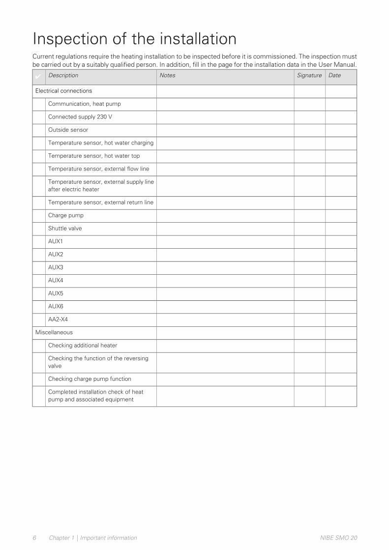
Inspection of the installationCurrent regulations require the heating installation to be inspected before it is commissioned. The inspection mustbe carried out by a suitably qualified person. In addition, fill in the page for the installation data in the User Manual.
DateSignatureNotesDescription✔
Electrical connections
Communication, heat pump
Connected supply 230 V
Outside sensor
Temperature sensor, hot water charging
Temperature sensor, hot water top
Temperature sensor, external flow line
Temperature sensor, external supply lineafter electric heater
Temperature sensor, external return line
Charge pump
Shuttle valve
AUX1
AUX2
AUX3
AUX4
AUX5
AUX6
AA2-X4
Miscellaneous
Checking additional heater
Checking the function of the reversingvalve
Checking charge pump function
Completed installation check of heatpump and associated equipment
NIBE SMO 20Chapter 1 | Important information6

System solutionsCOMPATIBLE PRODUCTSThe following combinations of products are recommended for control by SMO 20.
LEK
LEK
LEK
LEK
LE
K
LEK
LEK
LEK
Volume vesselAdditionWater heater
Circ. pumpAccumulatorwith hot waterheater
HW controlAir/water heatpump
Control mod-ule
UKV 40
UKV 100
UKV 200
UKV 300
UKV 500
ELK 15
ELK 26
ELK 42
VPB 200
VPB 300
VPBS 300
VPB 500
VPB 750-2
VPB 1000
CPD 11-25/65
CPD 11-25/75
VPA 450/300
VPAS 300/450
VPA 300/200
VPA 450/300
VPAS 300/450
VST 05
AMS 10-6 /HBS 05-6
SMO 20
AMS 10-8 /HBS 05-12F2040 – 6F2040 – 8F2120 – 8
VST 11
AMS 10-12 /HBS 05-12F2040 – 12F2120 – 12F2120 – 16
VPB 500
VPB 750-2
VPB 1000
VST 20
AMS 10-16 /HBS 05-16F2040 – 16F2120 – 20
7Chapter 1 | Important informationNIBE SMO 20

COMPATIBLE AIR/WATER HEAT PUMPS
NIBE SPLIT HBS 05
HBS 05-6
Part no. 067 578
AMS 10-6
Part no. 064 205
HBS 05-12
Part no. 067 480
AMS 10-8
Part no. 064 033
HBS 05-12
Part no. 067 480
AMS 10-12
Part no. 064 110
HBS 05-16
Part no. 067 536
AMS 10-16
Part no. 064 035
F2040
F2040-8Part no. 064 109
F2040-6Part no. 064 206
F2040-16Part no. 064 108
F2040-12Part no. 064 092
F2120
F2120-8 3x400VPart no. 064 135
F2120-8 1x230VPart no. 064 134
F2120-12 3x400VPart no. 064 137
F2120-12 1x230VPart no. 064 136
F2120-20 3x400VPart no. 064 141
F2120-16 3x400VPart no. 064 139
Check the software version of compatible older NIBEair/water heat pumps, see page 12.
NIBE SMO 20Chapter 1 | Important information8
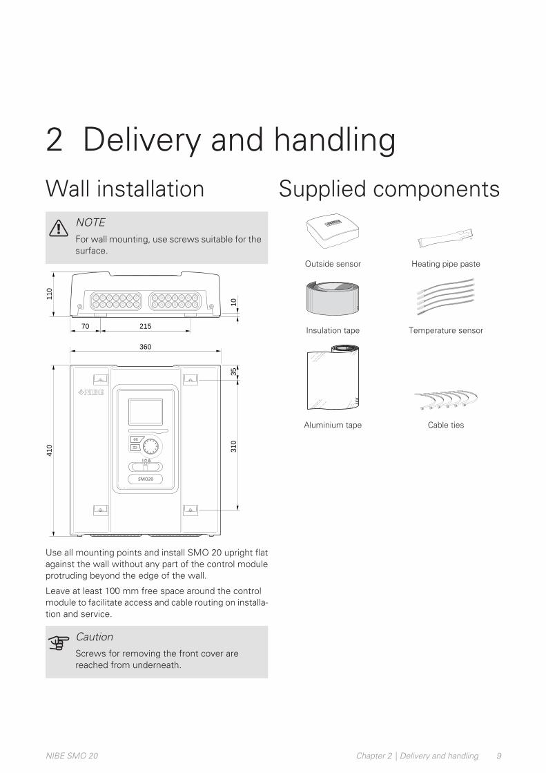
Wall installationNOTEFor wall mounting, use screws suitable for thesurface.
110
410
360
110
10
310
21570
35
Use all mounting points and install SMO 20 upright flatagainst the wall without any part of the control moduleprotruding beyond the edge of the wall.
Leave at least 100 mm free space around the controlmodule to facilitate access and cable routing on installa-tion and service.
CautionScrews for removing the front cover arereached from underneath.
Supplied components
Heating pipe pasteOutside sensor
LE
K
Temperature sensorInsulation tape
LE
K
Cable tiesAluminium tape
9Chapter 2 | Delivery and handlingNIBE SMO 20
2 Delivery and handling

Component positions
LEK
L N 1 1 0 2 3 4PE
21
20
19
18
17
16
15
14
13
12
11
10
98
76
54
32
1
AA2
AA4-XJ3
X1
SF1
AA4
X2
AA7
AA4-XJ4
LEK
L N 1 1 0 2 3 4PE
AA2
X1
FA1
AA7
UB2UB1
PF3
Electrical componentsBase cardAA2Display unitAA4
AA4-XJ3 USB socket
AA4-XJ4 Service outlet (No function)Extra relay circuit boardAA7Miniature circuit breaker, 10 AFA1Terminal block, incoming electrical supplyX1Terminal block, control signal circulation pump,sensors AUX inputs and heat pump
X2
SwitchSF1
Serial number platePF3Cable grommet, incoming supply electricity, powerfor accessories
UB1
Cable gland, signalUB2
Designations in component locations according to standard IEC 81346-1 and EN 81346-2.
NIBE SMO 20Chapter 3 | The Control Module Design10
3 The Control Module Design
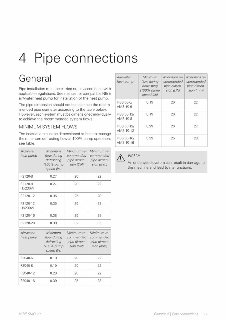
GeneralPipe installation must be carried out in accordance withapplicable regulations. See manual for compatible NIBEair/water heat pump for installation of the heat pump.
The pipe dimension should not be less than the recom-mended pipe diameter according to the table below.However, each system must be dimensioned individuallyto achieve the recommended system flows.
MINIMUM SYSTEM FLOWSThe installation must be dimensioned at least to managethe minimum defrosting flow at 100% pump operation,see table.
Minimum re-commendedpipe dimen-sion (mm)
Minimum re-commendedpipe dimen-sion (DN)
Minimumflow duringdefrosting
(100% pumpspeed (l/s)
Air/waterheat pump
22200.27F2120-8
22200.27F2120-8(1x230V)
28250.35F2120-12
28250.35F2120-12(1x230V)
28250.38F2120-16
35320.38F2120-20
Minimum re-commendedpipe dimen-sion (mm)
Minimum re-commendedpipe dimen-sion (DN)
Minimumflow duringdefrosting
(100% pumpspeed (l/s)
Air/waterheat pump
22200.19F2040-6
22200.19F2040-8
22200.29F2040-12
28250.39F2040-16
Minimum re-commendedpipe dimen-sion (mm)
Minimum re-commendedpipe dimen-sion (DN)
Minimumflow duringdefrosting
(100% pumpspeed (l/s)
Air/waterheat pump
22200.19HBS 05-6/AMS 10-6
22200.19HBS 05-12/AMS 10-8
22200.29HBS 05-12/AMS 10-12
28250.39HBS 05-16/AMS 10-16
NOTEAn undersized system can result in damage tothe machine and lead to malfunctions.
11Chapter 4 | Pipe connectionsNIBE SMO 20
4 Pipe connections

Compatible NIBEair/water heat pumpsCompatible NIBE air/water heat pump has to beequipped with a control board that, as a minimum, hasthe software version given in the following list. Thecontrol board’s version is shown in the heat pump’sdisplay (if applicable) at start-up.
Software versionProduct
55F2015
55F2016
118F2020
55F2025
55F2026
all versionsF2030
all versionsF2040
all versionsF2120
55F2300
all versionsNIBE SPLIT HBS 05:
AMS 10-6 + HBS 05-6
AMS 10-8 + HBS 05-12
AMS 10-12 + HBS 05-12
AMS 10-16 + HBS 05-16
Symbol keyMeaningSymbol
Shut-off valve
Tapping valve
Trim valve
Shunt / reversing valve
Safety valve
Temperature sensor
Expansion vessel
Pressure gaugeP
Circulation pump
Particle filter
Auxiliary relay
Compressor
Heat exchanger
Radiator system
Domestic hot water
Under floor heating systems
Cooling system
NIBE SMO 20Chapter 4 | Pipe connections12
Temperature sensorinstallation on pipe
LEK
LEK
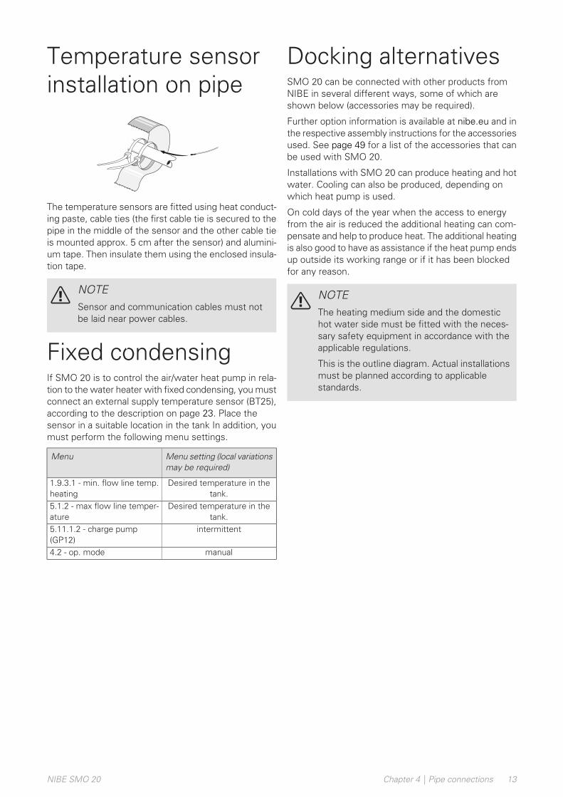
The temperature sensors are fitted using heat conduct-ing paste, cable ties (the first cable tie is secured to thepipe in the middle of the sensor and the other cable tieis mounted approx. 5 cm after the sensor) and alumini-um tape. Then insulate them using the enclosed insula-tion tape.
NOTESensor and communication cables must notbe laid near power cables.
Fixed condensingIf SMO 20 is to control the air/water heat pump in rela-tion to the water heater with fixed condensing, you mustconnect an external supply temperature sensor (BT25),according to the description on page 23. Place thesensor in a suitable location in the tank In addition, youmust perform the following menu settings.
Menu setting (local variationsmay be required)
Menu
Desired temperature in thetank.
1.9.3.1 - min. flow line temp.heating
Desired temperature in thetank.
5.1.2 - max flow line temper-ature
intermittent5.11.1.2 - charge pump(GP12)
manual4.2 - op. mode
Docking alternativesSMO 20 can be connected with other products fromNIBE in several different ways, some of which areshown below (accessories may be required).
Further option information is available at nibe.eu and inthe respective assembly instructions for the accessoriesused. See page 49 for a list of the accessories that canbe used with SMO 20.
Installations with SMO 20 can produce heating and hotwater. Cooling can also be produced, depending onwhich heat pump is used.
On cold days of the year when the access to energyfrom the air is reduced the additional heating can com-pensate and help to produce heat. The additional heatingis also good to have as assistance if the heat pump endsup outside its working range or if it has been blockedfor any reason.
NOTEThe heating medium side and the domestichot water side must be fitted with the neces-sary safety equipment in accordance with theapplicable regulations.
This is the outline diagram. Actual installationsmust be planned according to applicablestandards.
13Chapter 4 | Pipe connectionsNIBE SMO 20
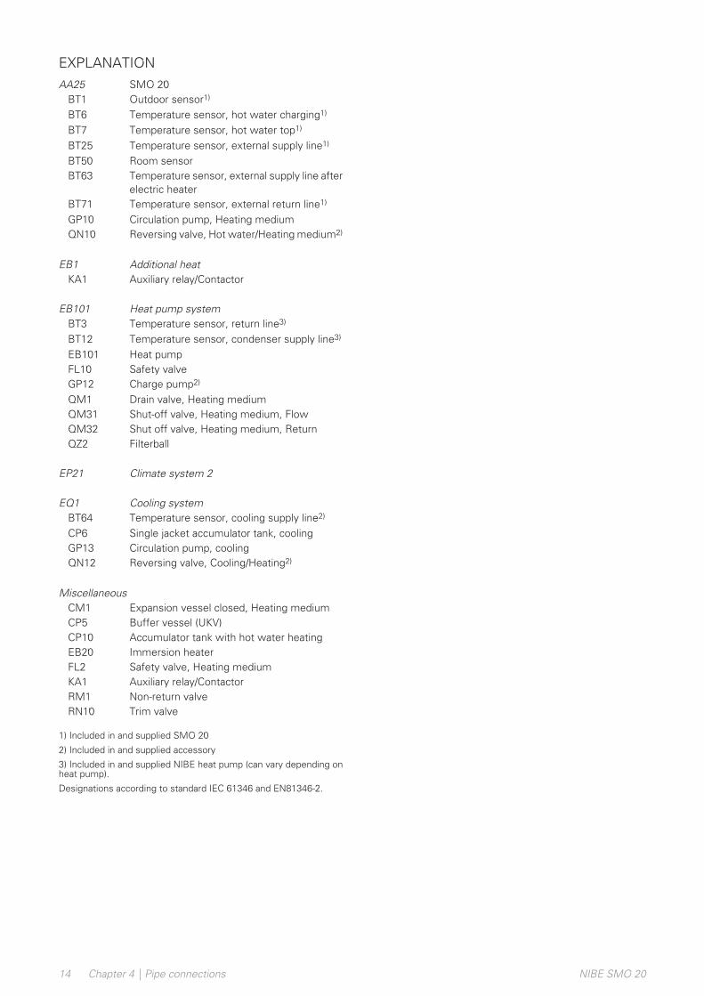
EXPLANATIONSMO 20AA25Outdoor sensor1)BT1Temperature sensor, hot water charging1)BT6Temperature sensor, hot water top1)BT7Temperature sensor, external supply line1)BT25Room sensorBT50Temperature sensor, external supply line afterelectric heater
BT63
Temperature sensor, external return line1)BT71Circulation pump, Heating mediumGP10Reversing valve, Hot water/Heating medium2)QN10
Additional heatEB1Auxiliary relay/ContactorKA1
Heat pump systemEB101Temperature sensor, return line3)BT3Temperature sensor, condenser supply line3)BT12Heat pumpEB101Safety valveFL10Charge pump2)GP12Drain valve, Heating mediumQM1Shut-off valve, Heating medium, FlowQM31Shut off valve, Heating medium, ReturnQM32FilterballQZ2
Climate system 2EP21
Cooling systemEQ1Temperature sensor, cooling supply line2)BT64Single jacket accumulator tank, coolingCP6Circulation pump, coolingGP13Reversing valve, Cooling/Heating2)QN12
MiscellaneousExpansion vessel closed, Heating mediumCM1Buffer vessel (UKV)CP5Accumulator tank with hot water heatingCP10Immersion heaterEB20Safety valve, Heating mediumFL2Auxiliary relay/ContactorKA1Non-return valveRM1Trim valveRN10
1) Included in and supplied SMO 20
2) Included in and supplied accessory
3) Included in and supplied NIBE heat pump (can vary depending onheat pump).
Designations according to standard IEC 61346 and EN81346-2.
NIBE SMO 20Chapter 4 | Pipe connections14
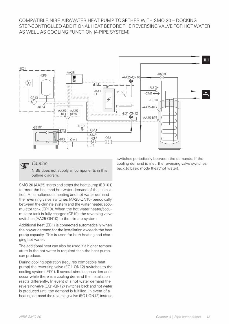
COMPATIBLE NIBE AIR/WATER HEAT PUMP TOGETHER WITH SMO 20 – DOCKINGSTEP-CONTROLLED ADDITIONAL HEAT BEFORE THE REVERSING VALVE FOR HOT WATERAS WELL AS COOLING FUNCTION (4-PIPE SYSTEM)
-FL2
-CM1
-EB101
-QM1-BT3
-BT12 -QM31
-GP12
-BT1
-AA25
-AA25
-AA25-BT50-AA25
-BT63-KA1
-EB1
-FL10
-QZ2
-RN10
-CP10
-AA25-QN10
-AA25-BT7
-AA25-BT6
-GP13
-CP6
-BT64
-EQ1-QN12
-EQ1
-EB1
CautionNIBE does not supply all components in thisoutline diagram.
SMO 20 (AA25) starts and stops the heat pump (EB101)to meet the heat and hot water demand of the installa-tion. At simultaneous heating and hot water demandthe reversing valve switches (AA25-QN10) periodicallybetween the climate system and the water heater/accu-mulator tank (CP10). When the hot water heater/accu-mulator tank is fully charged (CP10), the reversing valveswitches (AA25-QN10) to the climate system.
Additional heat (EB1) is connected automatically whenthe power demand for the installation exceeds the heatpump capacity. This is used for both heating and char-ging hot water.
The additional heat can also be used if a higher temper-ature in the hot water is required than the heat pumpcan produce.
During cooling operation (requires compatible heatpump) the reversing valve (EQ1-QN12) switches to thecooling system (EQ1). If several simultaneous demandsoccur while there is a cooling demand the installationreacts differently. In event of a hot water demand thereversing valve (EQ1-QN12) switches back and hot wateris produced until the demand is fulfilled. In event of aheating demand the reversing valve (EQ1-QN12) instead
switches periodically between the demands. If thecooling demand is met, the reversing valve switchesback to basic mode (heat/hot water).
15Chapter 4 | Pipe connectionsNIBE SMO 20
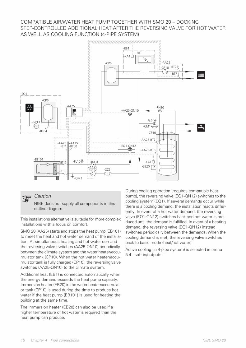
COMPATIBLE AIR/WATER HEAT PUMP TOGETHER WITH SMO 20 – DOCKINGSTEP-CONTROLLED ADDITIONAL HEAT AFTER THE REVERSING VALVE FOR HOT WATERAS WELL AS COOLING FUNCTION (4-PIPE SYSTEM)
-EB20
-KA1
-FL2
-CM1
-EB101
-QM1
-QM31
-GP12
-BT1
-AA25
-AA25 -AA25
-FL10
-BT3
-BT12
-AA25-QZ2
-RN10
-CP10
-AA25-QN10
-AA25-BT7
-AA25-BT6
-BT25
-EB1
-CP5
-GP10
-KA1
-BT71
-EB1
-AA25
-GP13
-CP6
-BT64
-EQ1-QN12
-EQ1
-BT50
CautionNIBE does not supply all components in thisoutline diagram.
This installations alternative is suitable for more complexinstallations with a focus on comfort.
SMO 20 (AA25) starts and stops the heat pump (EB101)to meet the heat and hot water demand of the installa-tion. At simultaneous heating and hot water demandthe reversing valve switches (AA25-QN10) periodicallybetween the climate system and the water heater/accu-mulator tank (CP10). When the hot water heater/accu-mulator tank is fully charged (CP10), the reversing valveswitches (AA25-QN10) to the climate system.
Additional heat (EB1) is connected automatically whenthe energy demand exceeds the heat pump capacity.Immersion heater (EB20) in the water heater/accumulat-or tank (CP10) is used during the time to produce hotwater if the heat pump (EB101) is used for heating thebuilding at the same time.
The immersion heater (EB20) can also be used if ahigher temperature of hot water is required than theheat pump can produce.
During cooling operation (requires compatible heatpump), the reversing valve (EQ1-QN12) switches to thecooling system (EQ1). If several demands occur whilethere is a cooling demand, the installation reacts differ-ently. In event of a hot water demand, the reversingvalve (EQ1-QN12) switches back and hot water is pro-duced until the demand is fulfilled. In event of a heatingdemand, the reversing valve (EQ1-QN12) insteadswitches periodically between the demands. When thecooling demand is met, the reversing valve switchesback to basic mode (heat/hot water).
Active cooling (in 4-pipe system) is selected in menu5.4 - soft in/outputs.
NIBE SMO 20Chapter 4 | Pipe connections16
General• Disconnect SMO 20 before insulation testing the
house wiring.
• If the building is equipped with an earth-fault breaker,SMO 20 should be equipped with a separate one.
• SMO 20 must be installed via a circuit breaker with aminimum breaking gap of 3 mm.
• For the electrical wiring diagram for the control mod-ule, see page .54.
• Use a three core, screened cable for communicationwith the heat pump.
• Communication and sensor cables to external connec-tions must not be laid close to high current cables.
• The minimum area of communication and sensorcables to external connections must be 0.5 mm² upto 50 m, for example EKKX, LiYY or equivalent.
• When cable routing into SMO 20, cable grommets(UB1 and UB2, marked in image) must be used.
NOTEThe switch (SF1) must not be moved to "" or" " until the boiler water has been filled in thesystem. The compressor in the heat pump andany external additional heat can be damaged.
NOTEElectrical installation and any servicing mustbe carried out under the supervision of a quali-fied electrician. Disconnect the current usingthe circuit breaker before carrying out any ser-vicing. Electrical installation and wiring mustbe carried out in accordance with the applicableprovisions. When installing SMO 20, NIBE’sair/water heat pump and any additional heatmust be disconnected from the power supply.
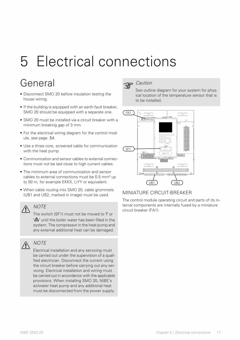
CautionSee outline diagram for your system for phys-ical location of the temperature sensor that isto be installed.
LEK
L N 1 1 0 2 3 4PE
21
20
19
18
17
16
15
14
13
12
11
10
98
76
54
32
1
SF1
FA1
UB2UB1
MINIATURE CIRCUIT-BREAKERThe control module operating circuit and parts of its in-ternal components are internally fused by a miniaturecircuit breaker (FA1).
17Chapter 5 | Electrical connectionsNIBE SMO 20
5 Electrical connections
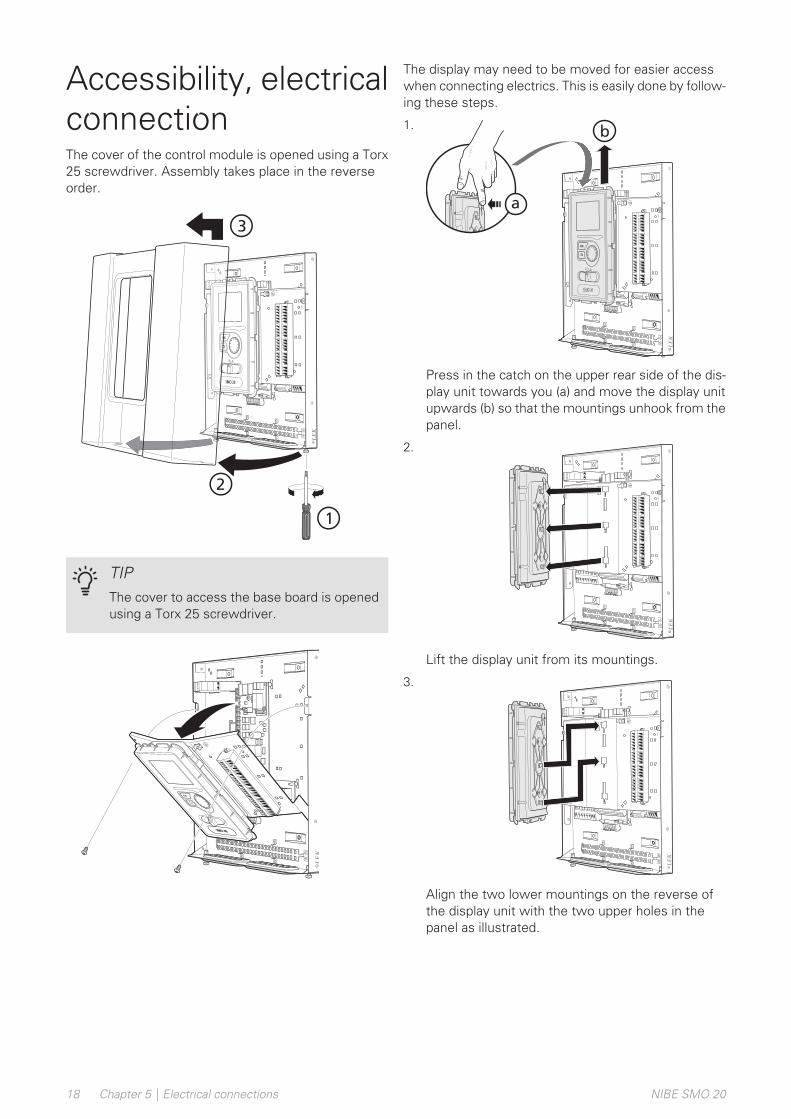
Accessibility, electricalconnectionThe cover of the control module is opened using a Torx25 screwdriver. Assembly takes place in the reverseorder.
3
1
2
LEK
LEK
TIPThe cover to access the base board is openedusing a Torx 25 screwdriver.
3
1
2
LEK
LEK
The display may need to be moved for easier accesswhen connecting electrics. This is easily done by follow-ing these steps.
1.
LEK
LEK
LEK
LEK
b
a
Press in the catch on the upper rear side of the dis-play unit towards you (a) and move the display unitupwards (b) so that the mountings unhook from thepanel.
2.
LEK
LEK
LEK
LEK
b
a
Lift the display unit from its mountings.
3.
LEK
LEK
LEK
LEK
b
a
Align the two lower mountings on the reverse ofthe display unit with the two upper holes in thepanel as illustrated.
NIBE SMO 20Chapter 5 | Electrical connections18

4.
LEK
LEK
LEK
LEK
b
a
Secure the display on the panel.
5. When the electrical connection is ready the displaymust be reinstalled with three mounting pointsagain, otherwise the front cover cannot be installed.
Cable lockUse a suitable tool to release/lock cables in the heatpump terminal blocks.
TERMINAL BLOCK ON THE ELECTRICALCARD
LE
K
1
1
2
2
3
3
1
2
3
3
4
1
2LE
K
1
1
2
2
3
3
1
2
3
3
4
1
2
1
2
TERMINAL BLOCK
LEK
1 mm
3,5 mm
LEK
1 mm
3,5 mm
19Chapter 5 | Electrical connectionsNIBE SMO 20
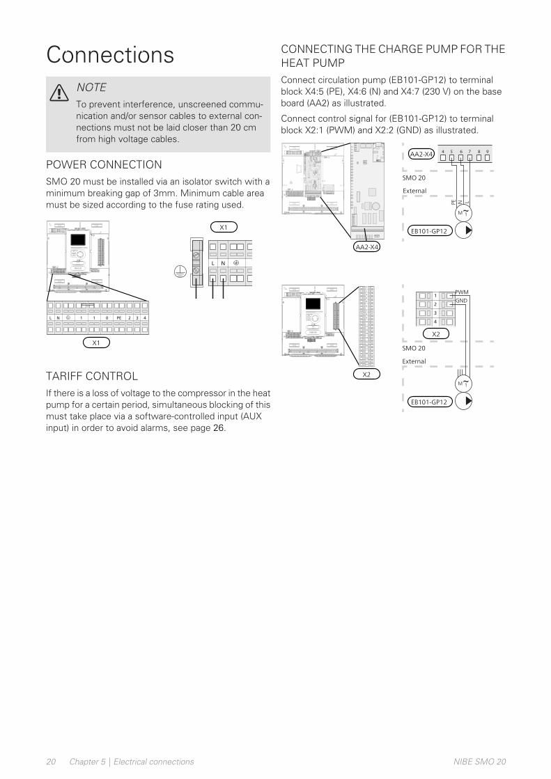
ConnectionsNOTETo prevent interference, unscreened commu-nication and/or sensor cables to external con-nections must not be laid closer than 20 cmfrom high voltage cables.
POWER CONNECTIONSMO 20 must be installed via an isolator switch with aminimum breaking gap of 3mm. Minimum cable areamust be sized according to the fuse rating used.
1NL
X1
LEK
L N 1 1 0 2 3 4PE
21
20
19
18
17
16
15
14
13
12
11
10
98
76
54
32
1
X1
1 1NL 0 432PE
TARIFF CONTROLIf there is a loss of voltage to the compressor in the heatpump for a certain period, simultaneous blocking of thismust take place via a software-controlled input (AUXinput) in order to avoid alarms, see page 26.
CONNECTING THE CHARGE PUMP FOR THEHEAT PUMPConnect circulation pump (EB101-GP12) to terminalblock X4:5 (PE), X4:6 (N) and X4:7 (230 V) on the baseboard (AA2) as illustrated.
Connect control signal for (EB101-GP12) to terminalblock X2:1 (PWM) and X2:2 (GND) as illustrated.
987654
SMO
Externt
PE LN
External
SMO 20
AA2-X4
EB101-GP12
LEK
L N 1 1 0 2 3 4PE
AA2-X4
2
1
4
3
SMO
ExterntExternal
SMO 20
X2
EB101-GP12
PWM
GND
LEK
L N 1 1 0 2 3 4PE2
12
01
91
81
71
61
51
41
31
211
10
98
76
54
32
1
X2
5
6
7
2
1
8
9
13
12
4
3
11
10
19
20
21
14
18
16
17
15
NIBE SMO 20Chapter 5 | Electrical connections20

COMMUNICATION WITH HEAT PUMPConnect the heat pump (EB101) with a screened threecore cable to terminal block X2:19 (A), X2:20 (B) andX2:21 (GND) as illustrated.
Connecting to the heat pump
LEK
L N 1 1 0 2 3 4PE
21
20
19
18
17
16
15
14
13
12
11
10
98
76
54
32
1
X2
5
6
7
2
1
8
9
13
12
4
3
11
10
19
20
21
14
18
16
17
15
A
B
GND
SMO
19
20
21
18
F2120
2
1
3
4
GND
B
A
6
5
4
3
2
1
A
B
GND
A
B
GND
F2040
A
B
GND
F2030
54
23
1
A
B
GND
F2016/F2026
56
42
31
A
B
GND
F2015/F2020/F2025/F2300
X2
SMO 20
AA21-J2
X5
X5
AA23-X4
X22
F2040
F2030
F2016/F2026
F2015/F2020/F2025/F2300
F2120
21Chapter 5 | Electrical connectionsNIBE SMO 20
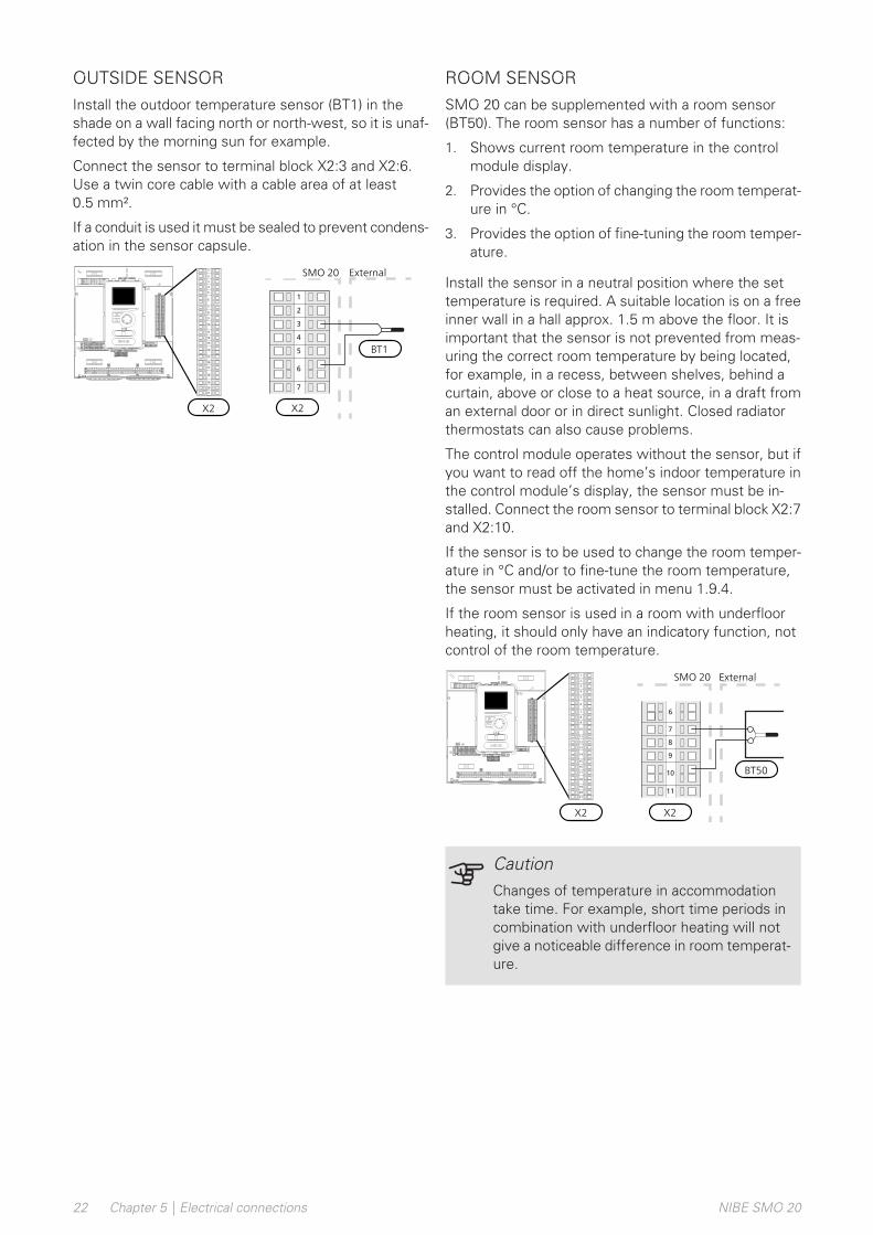
OUTSIDE SENSORInstall the outdoor temperature sensor (BT1) in theshade on a wall facing north or north-west, so it is unaf-fected by the morning sun for example.
Connect the sensor to terminal block X2:3 and X2:6.Use a twin core cable with a cable area of at least0.5 mm².
If a conduit is used it must be sealed to prevent condens-ation in the sensor capsule.
SMO Externt
5
6
7
2
1
4
3
ExternalSMO 20
X2
BT1
LEK
L N 1 1 0 2 3 4PE
21
20
19
18
17
16
15
14
13
12
11
10
98
76
54
32
1
X2
5
6
7
2
1
8
9
13
12
4
3
11
10
19
20
21
14
18
16
17
15
ROOM SENSORSMO 20 can be supplemented with a room sensor(BT50). The room sensor has a number of functions:
1. Shows current room temperature in the controlmodule display.
2. Provides the option of changing the room temperat-ure in °C.
3. Provides the option of fine-tuning the room temper-ature.
Install the sensor in a neutral position where the settemperature is required. A suitable location is on a freeinner wall in a hall approx. 1.5 m above the floor. It isimportant that the sensor is not prevented from meas-uring the correct room temperature by being located,for example, in a recess, between shelves, behind acurtain, above or close to a heat source, in a draft froman external door or in direct sunlight. Closed radiatorthermostats can also cause problems.
The control module operates without the sensor, but ifyou want to read off the home’s indoor temperature inthe control module’s display, the sensor must be in-stalled. Connect the room sensor to terminal block X2:7and X2:10.
If the sensor is to be used to change the room temper-ature in °C and/or to fine-tune the room temperature,the sensor must be activated in menu 1.9.4.
If the room sensor is used in a room with underfloorheating, it should only have an indicatory function, notcontrol of the room temperature.
SMO Externt
9
10
11
6
8
7
ExternalSMO 20
X2
BT50LEK
L N 1 1 0 2 3 4PE
21
20
19
18
17
16
15
14
13
12
11
10
98
76
54
32
1
X2
5
6
7
2
1
8
9
13
12
4
3
11
10
19
20
21
14
18
16
17
15
CautionChanges of temperature in accommodationtake time. For example, short time periods incombination with underfloor heating will notgive a noticeable difference in room temperat-ure.
NIBE SMO 20Chapter 5 | Electrical connections22
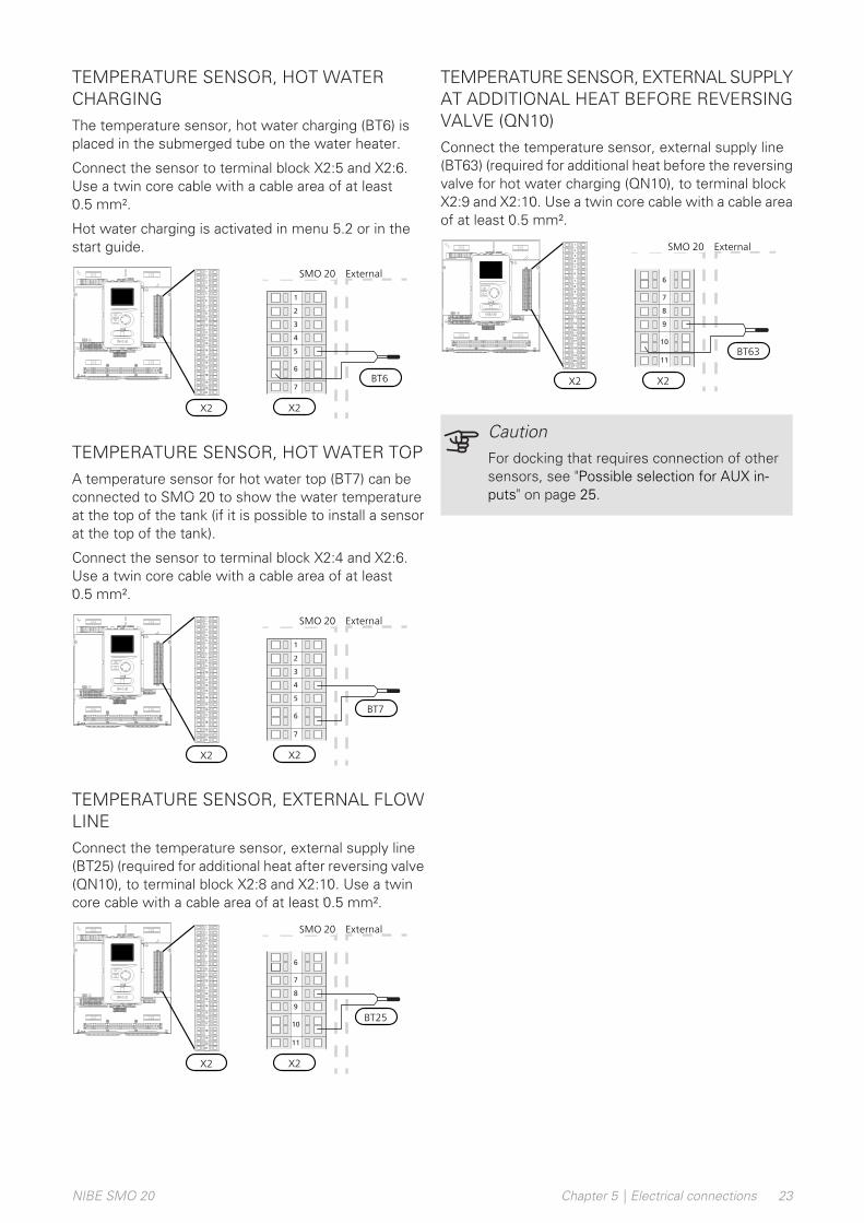
TEMPERATURE SENSOR, HOT WATERCHARGINGThe temperature sensor, hot water charging (BT6) isplaced in the submerged tube on the water heater.
Connect the sensor to terminal block X2:5 and X2:6.Use a twin core cable with a cable area of at least0.5 mm².
Hot water charging is activated in menu 5.2 or in thestart guide.
SMO Externt
5
6
7
2
1
4
3
ExternalSMO 20
X2
BT6LEK
L N 1 1 0 2 3 4PE
21
20
19
18
17
16
15
14
13
12
11
10
98
76
54
32
1
X2
5
6
7
2
1
8
9
13
12
4
3
11
10
19
20
21
14
18
16
17
15
TEMPERATURE SENSOR, HOT WATER TOPA temperature sensor for hot water top (BT7) can beconnected to SMO 20 to show the water temperatureat the top of the tank (if it is possible to install a sensorat the top of the tank).
Connect the sensor to terminal block X2:4 and X2:6.Use a twin core cable with a cable area of at least0.5 mm².
SMO Externt
5
6
7
2
1
4
3
ExternalSMO 20
X2
BT7LEK
L N 1 1 0 2 3 4PE
21
20
19
18
17
16
15
14
13
12
11
10
98
76
54
32
1
X2
5
6
7
2
1
8
9
13
12
4
3
11
10
19
20
21
14
18
16
17
15
TEMPERATURE SENSOR, EXTERNAL FLOWLINEConnect the temperature sensor, external supply line(BT25) (required for additional heat after reversing valve(QN10), to terminal block X2:8 and X2:10. Use a twincore cable with a cable area of at least 0.5 mm².
SMO Externt
9
10
11
6
8
7
ExternalSMO 20
X2
BT25LEK
L N 1 1 0 2 3 4PE
21
20
19
18
17
16
15
14
13
12
11
10
98
76
54
32
1
X2
5
6
7
2
1
8
9
13
12
4
3
11
10
19
20
21
14
18
16
17
15
TEMPERATURE SENSOR, EXTERNAL SUPPLYAT ADDITIONAL HEAT BEFORE REVERSINGVALVE (QN10)Connect the temperature sensor, external supply line(BT63) (required for additional heat before the reversingvalve for hot water charging (QN10), to terminal blockX2:9 and X2:10. Use a twin core cable with a cable areaof at least 0.5 mm².
SMO Externt
9
10
11
6
8
7
ExternalSMO 20
X2
BT63LEK
L N 1 1 0 2 3 4PE
21
20
19
18
17
16
15
14
13
12
11
10
98
76
54
32
1
X2
5
6
7
2
1
8
9
13
12
4
3
11
10
19
20
21
14
18
16
17
15
CautionFor docking that requires connection of othersensors, see "Possible selection for AUX in-puts" on page 25.
23Chapter 5 | Electrical connectionsNIBE SMO 20
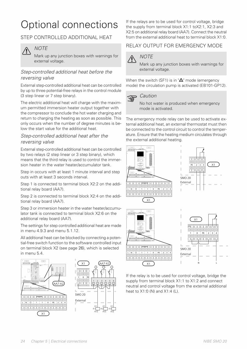
Optional connectionsSTEP CONTROLLED ADDITIONAL HEAT
NOTEMark up any junction boxes with warnings forexternal voltage.
Step-controlled additional heat before thereversing valveExternal step-controlled additional heat can be controlledby up to three potential-free relays in the control module(3 step linear or 7 step binary).
The electric additional heat will charge with the maxim-um permitted immersion heater output together withthe compressor to conclude the hot water charging andreturn to charging the heating as soon as possible. Thisonly occurs when the number of degree minutes is be-low the start value for the additional heat.
Step-controlled additional heat after thereversing valveExternal step-controlled additional heat can be controlledby two relays (2 step linear or 3 step binary), whichmeans that the third relay is used to control the immer-sion heater in the water heater/accumulator tank.
Step in occurs with at least 1 minute interval and stepouts with at least 3 seconds interval.
Step 1 is connected to terminal block X2:2 on the addi-tional relay board (AA7).
Step 2 is connected to terminal block X2:4 on the addi-tional relay board (AA7).
Step 3 or immersion heater in the water heater/accumu-lator tank is connected to terminal block X2:6 on theadditional relay board (AA7).
The settings for step controlled additional heat are madein menu 4.9.3 and menu 5.1.12.
All additional heat can be blocked by connecting a poten-tial-free switch function to the software controlled inputon terminal block X2 (see page 26), which is selectedin menu 5.4.
SMO
Externt
654321
1 0 PE
A1
A2
A1
A2
A1
-K1 -K2 -K3
A2
External
SMO 20
AA7-X2X1
LEK
L N 1 1 0 2 3 4PE
X1
1 1NL 0 432PE
-X2
1
123456
2 3 4 5 6
-X1
AA7-X2
If the relays are to be used for control voltage, bridgethe supply from terminal block X1:1 toX2:1, X2:3 andX2:5 on additional relay board (AA7). Connect the neutralfrom the external additional heat to terminal block X1:0.
RELAY OUTPUT FOR EMERGENCY MODE
NOTEMark up any junction boxes with warnings forexternal voltage.
When the switch (SF1) is in " " mode (emergencymode) the circulation pump is activated (EB101-GP12).
CautionNo hot water is produced when emergencymode is activated.
The emergency mode relay can be used to activate ex-ternal additional heat, an external thermostat must thenbe connected to the control circuit to control the temper-ature. Ensure that the heating medium circulates throughthe external additional heating.
432PE
SMO
Externt
X1
ExternalSMO 20
LEK
L N 1 1 0 2 3 4PE
21
20
19
18
17
16
15
14
13
12
11
10
98
76
54
32
1
X1
1 1NL 0 432PE
1 0 432PE
SMO
Externt
N L
X1
External
SMO 20
LEK
L N 1 1 0 2 3 4PE
21
20
19
18
17
16
15
14
13
12
11
10
98
76
54
32
1
X1
1 1NL 0 432PE
If the relay is to be used for control voltage, bridge thesupply from terminal block X1:1 to X1:2 and connectneutral and control voltage from the external additionalheat to X1:0 (N) and X1:4 (L).
NIBE SMO 20Chapter 5 | Electrical connections24
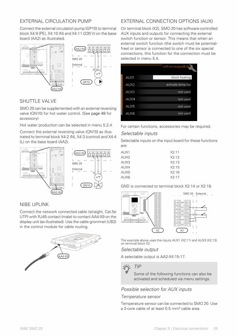
EXTERNAL CIRCULATION PUMPConnect the external circulation pump (GP10) to terminalblock X4:9 (PE), X4:10 (N) and X4:11 (230 V) on the baseboard (AA2) as illustrated.
1312111098
SMO
Externt
PE LN
External
SMO 20
AA2-X4
GP10
LEK
L N 1 1 0 2 3 4PE
AA2-X4
SHUTTLE VALVESMO 20 can be supplemented with an external reversingvalve (QN10) for hot water control. (See page 49 foraccessory)
Hot water production can be selected in menu 5.2.4.
Connect the external reversing valve (QN10) as illus-trated to terminal block X4:2 (N), X4:3 (control) and X4:4(L) on the base board (AA2).
654321
SMO
Externt
N L
External
SMO 20
QN10
AA2-X4
LEK
L N 1 1 0 2 3 4PE
AA2-X4
NIBE UPLINKConnect the network connected cable (straight, Cat.5eUTP) with RJ45 contact (male) to contact AA4-X9 on thedisplay unit (as illustrated). Use the cable grommet (UB2)in the control module for cable routing.
LEK
AA4-X9
EXTERNAL CONNECTION OPTIONS (AUX)On terminal block (X2), SMO 20 has software-controlledAUX inputs and outputs for connecting the externalswitch function or sensor. This means that when anexternal switch function (the switch must be potential-free) or sensor is connected to one of the six specialconnections, this function for the connection must beselected in menu 5.4.
block heating
activate temp lux
not used
soft in/outputs5.4
not used
not used
not used
For certain functions, accessories may be required.
Selectable inputsSelectable inputs on the input board for these functionsare:
X2:11AUX1X2:12AUX2X2:13AUX3X2:15AUX4X2:16AUX5X2:17AUX6
GND is connected to terminal block X2:14 or X2:18.
B
SMO Externt
13
14
15
10
12
11
A
ExternalSMO 20
X2
LEK
L N 1 1 0 2 3 4PE
21
20
19
18
17
16
15
14
13
12
11
10
98
76
54
32
1
X2
5
6
7
2
1
8
9
13
12
4
3
11
10
19
20
21
14
18
16
17
15
The example above uses the inputs AUX1 (X2:11) and AUX3 (X2:13)on terminal block X2.
Selectable outputA selectable output is AA2-X4:15-17.
TIPSome of the following functions can also beactivated and scheduled via menu settings.
Possible selection for AUX inputsTemperature sensor
Temperature sensor can be connected to SMO 20. Usea 2-core cable of at least 0.5 mm² cable area.
25Chapter 5 | Electrical connectionsNIBE SMO 20
Available options are:
• external supply temperature sensor cooling (EQ1-BT25) is used when docking 2-pipe cooling. (can beselected when the air/water heat pump is permittedto produce cooling)
• cooling/heating (BT74), determines when it is time toswitch between cooling and heating mode (can beselected when the air/water heat pump is permittedto produce cooling)
• supply cooling (BT64) is used with active cooling 4-pipe (can be selected when the air/water heat pumpis permitted to produce cooling)
• return temperature (BT71)
Monitor
Available options are:
• alarm from external units. The alarm is connected tothe control, which means that the malfunction ispresented as an information message in the display.Potential-free signal of type NO or NC.
External activation of functions
An external switch function can be connected toSMO 20 to activate various functions. The function isactivated during the time the switch is closed.
Possible functions that can be activated:
• hot water comfort mode “temporary lux”
• hot water comfort mode “economy”
• “external adjustment”
An external contact function can be connected toSMO 20 to change the supply temperature and theroom temperature.
When the switch is closed, the temperature ischanged in °C (if the room sensor is connected andactivated). If a room sensor is not connected or notactivated, the desired change of "temperature" (heatingcurve offset) is set with the number of steps selected.The value is adjustable between -10 and +10.
– climate system 1
The value for the change is set in menu 1.9.2, "ex-ternal adjustment".
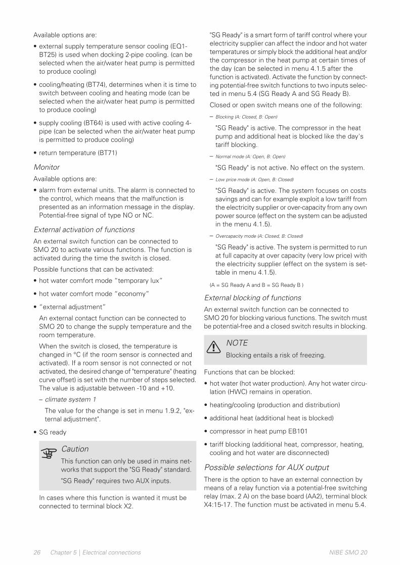
• SG ready
CautionThis function can only be used in mains net-works that support the "SG Ready" standard.
"SG Ready" requires two AUX inputs.
In cases where this function is wanted it must beconnected to terminal block X2.
"SG Ready" is a smart form of tariff control where yourelectricity supplier can affect the indoor and hot watertemperatures or simply block the additional heat and/orthe compressor in the heat pump at certain times ofthe day (can be selected in menu 4.1.5 after thefunction is activated). Activate the function by connect-ing potential-free switch functions to two inputs selec-ted in menu 5.4 (SG Ready A and SG Ready B).
Closed or open switch means one of the following:
– Blocking (A: Closed, B: Open)
"SG Ready" is active. The compressor in the heatpump and additional heat is blocked like the day'stariff blocking.
– Normal mode (A: Open, B: Open)
"SG Ready" is not active. No effect on the system.
– Low price mode (A: Open, B: Closed)
"SG Ready" is active. The system focuses on costssavings and can for example exploit a low tariff fromthe electricity supplier or over-capacity from any ownpower source (effect on the system can be adjustedin the menu 4.1.5).
– Overcapacity mode (A: Closed, B: Closed)
"SG Ready" is active. The system is permitted to runat full capacity at over capacity (very low price) withthe electricity supplier (effect on the system is set-table in menu 4.1.5).
(A = SG Ready A and B = SG Ready B )
External blocking of functions
An external switch function can be connected toSMO 20 for blocking various functions. The switch mustbe potential-free and a closed switch results in blocking.
NOTEBlocking entails a risk of freezing.
Functions that can be blocked:
• hot water (hot water production). Any hot water circu-lation (HWC) remains in operation.
• heating/cooling (production and distribution)
• additional heat (additional heat is blocked)
• compressor in heat pump EB101
• tariff blocking (additional heat, compressor, heating,cooling and hot water are disconnected)
Possible selections for AUX outputThere is the option to have an external connection bymeans of a relay function via a potential-free switchingrelay (max. 2 A) on the base board (AA2), terminal blockX4:15-17. The function must be activated in menu 5.4.
NIBE SMO 20Chapter 5 | Electrical connections26
17161514
SMO
ExterntExternal
SMO 20
AA2-X4
LEK
L N 1 1 0 2 3 4PE
AA2-X4
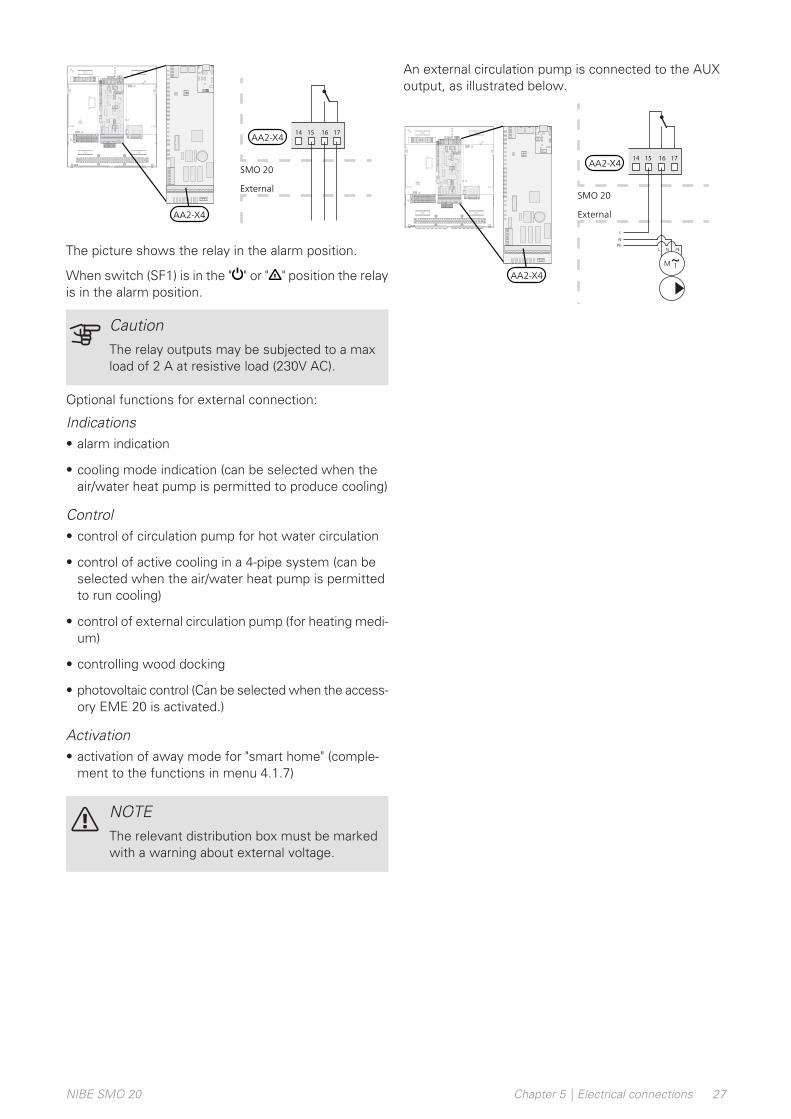
The picture shows the relay in the alarm position.
When switch (SF1) is in the " " or " " position the relayis in the alarm position.
CautionThe relay outputs may be subjected to a maxload of 2 A at resistive load (230V AC).
Optional functions for external connection:
Indications• alarm indication
• cooling mode indication (can be selected when theair/water heat pump is permitted to produce cooling)
Control• control of circulation pump for hot water circulation
• control of active cooling in a 4-pipe system (can beselected when the air/water heat pump is permittedto run cooling)
• control of external circulation pump (for heating medi-um)
• controlling wood docking
• photovoltaic control (Can be selected when the access-ory EME 20 is activated.)
Activation• activation of away mode for "smart home" (comple-
ment to the functions in menu 4.1.7)
NOTEThe relevant distribution box must be markedwith a warning about external voltage.
An external circulation pump is connected to the AUXoutput, as illustrated below.
17161514
SMO
Externt
L
L
N
N
PEPE
External
SMO 20
AA2-X4
LEK
L N 1 1 0 2 3 4PE
AA2-X4
27Chapter 5 | Electrical connectionsNIBE SMO 20

ConnectingaccessoriesInstructions for connecting other accessories are in theinstallation instructions provided. See page 49 for a listof those accessories that can be used for SMO 20.
NIBE SMO 20Chapter 5 | Electrical connections28
Preparations• Compatible NIBE air/water heat pump must be
equipped with a control board that, as a minimum,has the software version as listed on page 12. Thecontrol board’s version is shown in the heat pump’sdisplay (if applicable) at start-up.
• SMO 20 must be ready-connected.
• The climate system must be filled with water and bled.
CommissioningWITH NIBE AIR/WATER HEAT PUMPFollow the instructions in the heat pump's InstallerManual under section "Commissioning and adjustment"– "Start-up and inspection".
SMO 201. Power the heat pump.
2. Power SMO 20.
3. Follow the start guide in the display on SMO 20 al-ternatively start the start guide in menu 5.7.
Commissioning withadditional heating onlyAt first start follow the start guide, otherwise follow thelist below.
1. Configure the additional heat in menu 5.1.12.
2. Go to menu 4.2 op. mode.
3. Mark ”add. heat only” using the control knob andthen press the OK button.
4. Return to the main menus by pressing the Backbutton.
CautionWhen commissioning without NIBE air/waterheat pump an alarm communication error mayappear in the display.
The alarm is reset if the relevant air/water heatpump is deactivated in menu 5.2.2 ("installedheat pump").
Check the reversingvalve1. Activate "AA2-K1 (QN10)" in menu 5.6.
2. Check that the reversing valve opens or is open forhot water charging.
3. Deactivate "AA2-K1 (QN10)" in menu 5.6.
Check AUX socketTo check any function connected to the AUX socket
1. Activate "AA2-X4" in menu 5.6.
2. Check the desired function.
3. Deactivate "AA2-X4" in menu 5.6.
Cooling modeIf the installation contains a NIBE air/water heat pumpthat can produce cooling (NIBE F2040 or F2120) coolingcan be permitted. See relevant Installer Manual.
When cooling operation is permitted you can choosecooling mode indication in menu 5.4 for the AUX output.
29Chapter 6 | Commissioning and adjustingNIBE SMO 20
6 Commissioning and adjusting
Start-up andinspectionSTART GUIDE
NOTEThere must be water in the climate systembefore the switch is set to " ".
1. Set switch (SF1) on SMO 20 to position "".
2. Follow the instructions in the display's start guide.If the start guide does not start when you start theSMO 20, start it manually in menu 5.7.
TIPSee the section "Control – Introduction" for amore detailed introduction to the installation’scontrol system (operation, menus, etc.).
CommissioningThe first time the installation is started a start guide isstarted. The start guide instructions state what needsto carried out at the first start together with a runthrough of the installation’s basic settings.
The start guide ensures that start-up is carried out cor-rectly and cannot be bypassed. The start guide can bestarted later in menu 5.7.
During the start-up guide, the reversing valves and theshunt are run back and forth to help vent the heat pump.
CautionAs long as the start guide is active, no functionin SMO 20 will start automatically.
The start guide will appear at each restart ofSMO 20, until it is deselected on the last page.
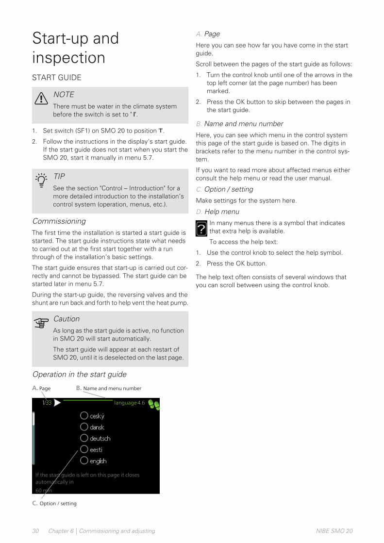
Operation in the start guide
language4.6
If the start guide is left on this page it closesautomatically in
60 min
A.Page
C. Option / setting
B. Name and menu number
A. Page
Here you can see how far you have come in the startguide.
Scroll between the pages of the start guide as follows:
1. Turn the control knob until one of the arrows in thetop left corner (at the page number) has beenmarked.
2. Press the OK button to skip between the pages inthe start guide.
B. Name and menu number
Here, you can see which menu in the control systemthis page of the start guide is based on. The digits inbrackets refer to the menu number in the control sys-tem.
If you want to read more about affected menus eitherconsult the help menu or read the user manual.
C. Option / setting
Make settings for the system here.
D. Help menu
In many menus there is a symbol that indicatesthat extra help is available.
To access the help text:
1. Use the control knob to select the help symbol.
2. Press the OK button.
The help text often consists of several windows thatyou can scroll between using the control knob.
NIBE SMO 20Chapter 6 | Commissioning and adjusting30

Display unit
A
B
C
D
E
F
Display
Status lamp
OK button
Back button
Control knob
Switch
INDOOR CLIMATE
HOTWATER
INFO
HEAT PUMP
SMO 20 G USB port
DISPLAYInstructions, settings and operational informationare shown on the display. You can easily navigatebetween the different menus and options to set thecomfort or obtain the information you require.
A
STATUS LAMPThe status lamp indicates the status of the controlmodule. It:
• lights green during normal operation.
• lights yellow in emergency mode.
• lights red in the event of a deployed alarm.
B
OK BUTTONThe OK button is used to:
• confirm selections of sub menus/options/set val-ues/page in the start guide.
C
BACK BUTTONThe back button is used to:
• go back to the previous menu.
• change a setting that has not been confirmed.
D
CONTROL KNOBThe control knob can be turned to the right or left.You can:
• scroll in menus and between options.
• increase and decrease the values.
• change page in multiple page instructions (forexample help text and service info).
E
SWITCH (SF1)The switch assumes three positions:
• On ( )
• Standby ( )
• Emergency mode ( )
The emergency mode must only be used in theevent of a fault in the control module. In this mode,the compressor in the heat pump switches off andany immersion heater engages. The control moduledisplay is not lit and the status lamp shines yellow.
F
USB PORTThe USB port is hidden beneath the plastic badgewith the product name on it.
The USB port is used to update the software.
Visit nibeuplink.com and click the "Software" tab todownload the latest software for your installation.
G
31Chapter 7 | Control - IntroductionNIBE SMO 20
7 Control - Introduction
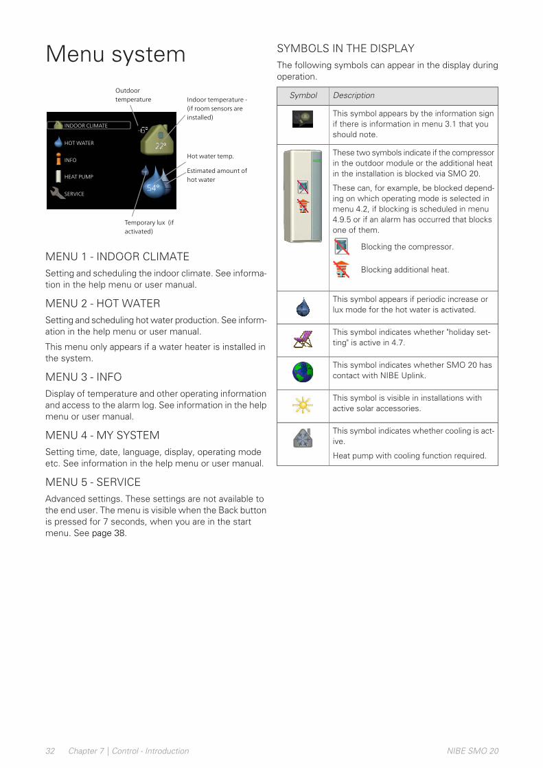
Menu system
INDOOR CLIMATE
HOTWATER
INFO
HEAT PUMP
SERVICE
Indoor temperature -(if room sensors areinstalled)
Hot water temp.
Temporary lux (ifactivated)
Outdoortemperature
Estimated amount ofhot water
MENU 1 - INDOOR CLIMATESetting and scheduling the indoor climate. See informa-tion in the help menu or user manual.
MENU 2 - HOT WATERSetting and scheduling hot water production. See inform-ation in the help menu or user manual.
This menu only appears if a water heater is installed inthe system.
MENU 3 - INFODisplay of temperature and other operating informationand access to the alarm log. See information in the helpmenu or user manual.
MENU 4 - MY SYSTEMSetting time, date, language, display, operating modeetc. See information in the help menu or user manual.
MENU 5 - SERVICEAdvanced settings. These settings are not available tothe end user. The menu is visible when the Back buttonis pressed for 7 seconds, when you are in the startmenu. See page 38.
SYMBOLS IN THE DISPLAYThe following symbols can appear in the display duringoperation.
DescriptionSymbol
This symbol appears by the information signif there is information in menu 3.1 that youshould note.
These two symbols indicate if the compressorin the outdoor module or the additional heatin the installation is blocked via SMO 20.
These can, for example, be blocked depend-ing on which operating mode is selected inmenu 4.2, if blocking is scheduled in menu4.9.5 or if an alarm has occurred that blocksone of them.
Blocking the compressor.
Blocking additional heat.
This symbol appears if periodic increase orlux mode for the hot water is activated.
This symbol indicates whether "holiday set-ting" is active in 4.7.
This symbol indicates whether SMO 20 hascontact with NIBE Uplink.
This symbol is visible in installations withactive solar accessories.
This symbol indicates whether cooling is act-ive.
Heat pump with cooling function required.
NIBE SMO 20Chapter 7 | Control - Introduction32

INDOOR CLIMATE
HOTWATER
INFO
HEAT PUMP
temperature
INDOOR CLIMATE 1
advanced
scheduling off
Marked mainmenu
Menu number – marked sub menu Name and menu number – main menu
Symbol –main menu
Status information – submenus
Name – sub menusSymbols – sub menus
OPERATIONTo move the cursor, turn the control knobto the left or the right. The marked positionis brighter and/or has a light frame.
SELECTING MENUTo advance in the menu system select a main menu bymarking it and then pressing the OK button. A newwindow then opens with sub menus.
Select one of the sub menus by marking it and thenpressing the OK button.
SELECTING OPTIONS
economy
comfort mode 2.2
normal
luxury
smart control
In an options menu the current selected option isindicated by a green tick.
To select another option:
1. Mark the applicable option. One of the optionsis pre-selected (white).
2. Press the OK button to confirm the selectedoption. The selected option has a green tick.
SETTING A VALUE
time & date4.4time
day
year
month
24 h
12 h
date
Values to be changed
To set a value:
1. Mark the value you want to set using thecontrol knob.
2. Press the OK button. The background of thevalue becomes green, which means that youhave accessed the setting mode.
3. Turn the control knob to the right to increasethe value and to the left to reduce the value.
4. Press the OK button to confirm the value youhave set. To change and return to the originalvalue, press the Back button.
33Chapter 7 | Control - IntroductionNIBE SMO 20
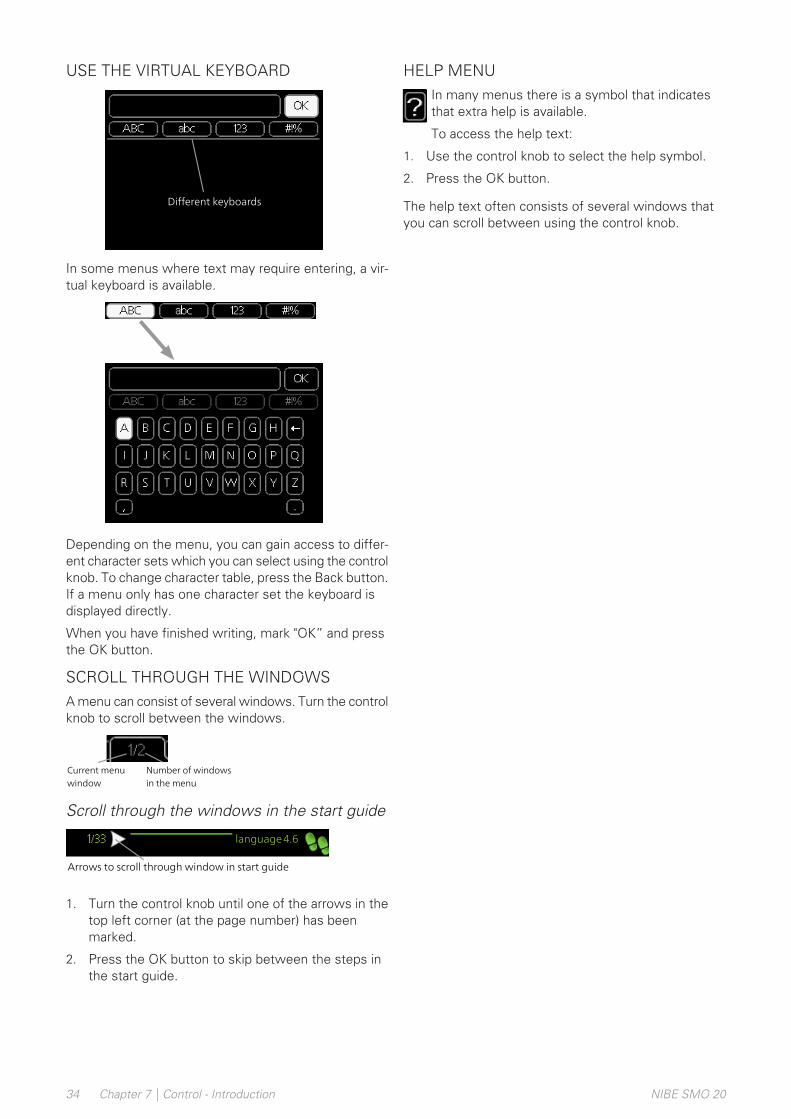
USE THE VIRTUAL KEYBOARD
Different keyboards
In some menus where text may require entering, a vir-tual keyboard is available.
Depending on the menu, you can gain access to differ-ent character sets which you can select using the controlknob. To change character table, press the Back button.If a menu only has one character set the keyboard isdisplayed directly.
When you have finished writing, mark "OK” and pressthe OK button.
SCROLL THROUGH THE WINDOWSA menu can consist of several windows. Turn the controlknob to scroll between the windows.
Current menuwindow
Number of windowsin the menu
Scroll through the windows in the start guide
language4.6
If the start guide is left on this page it closesautomatically in
60 min
Arrows to scroll through window in start guide
1. Turn the control knob until one of the arrows in thetop left corner (at the page number) has beenmarked.
2. Press the OK button to skip between the steps inthe start guide.
HELP MENUIn many menus there is a symbol that indicatesthat extra help is available.
To access the help text:
1. Use the control knob to select the help symbol.
2. Press the OK button.
The help text often consists of several windows thatyou can scroll between using the control knob.
NIBE SMO 20Chapter 7 | Control - Introduction34

Menu 1 - INDOOR CLIMATE1.1.1 - heating1.1 - temperature1 - INDOOR CLIMATE1.1.2 - cooling *
1.3.1 - heating1.3 - scheduling1.3.2 - cooling *
1.9.1.1 heating curve1.9.1 - curve1.9 - advanced1.9.1.2 - cooling curve *
1.9.2 - external adjustment
1.9.3.1 - heating1.9.3 - min. flow line temp.1.9.3.2 - cooling *
1.9.4 - room sensor settings1.9.5 - cooling settings *
1.9.7.1 - heating1.9.7 - own curve1.9.7.2 - cooling *
1.9.8 - point offset
* Heat pump with cooling function required.
35Chapter 8 | ControlNIBE SMO 20
8 Control

Menu 2 - HOT WATER2.1 - temporary lux2 - HOT WATER2.2 - comfort mode2.3 - scheduling
2.9.1 - periodic increase2.9 - advanced2.9.2 - hot water recirc. *
Menu 3 - INFO3.1 - service info3 - INFO3.2 - compressor info3.3 - add. heat info3.4 - alarm log3.5 - indoor temp. log
* Accessories are needed.
NIBE SMO 20Chapter 8 | Control36

Menu 4 - MY SYSTEM4.1.3.1 - NIBE Uplink4.1.3 - internet4.1 - plus functions4 - MY SYSTEM4.1.3.8 - tcp/ip settings4.1.3.9 - proxy settings
4.1.5 - SG Ready4.1.6 - smart price adaption™4.1.7 - smart homeMenu 4.1.10 – solar electricity*
4.2 - op. mode4.4 - time & date4.6 - language4.7 - holiday setting
4.9.1 - op. prioritisation4.9 - advanced4.9.2 - auto mode setting4.9.3 - degree minute setting4.9.4 - factory setting user4.9.5 - schedule blocking4.9.6 - schedule silent mode4.9.7 – tools
* Accessories are needed.
37Chapter 8 | ControlNIBE SMO 20
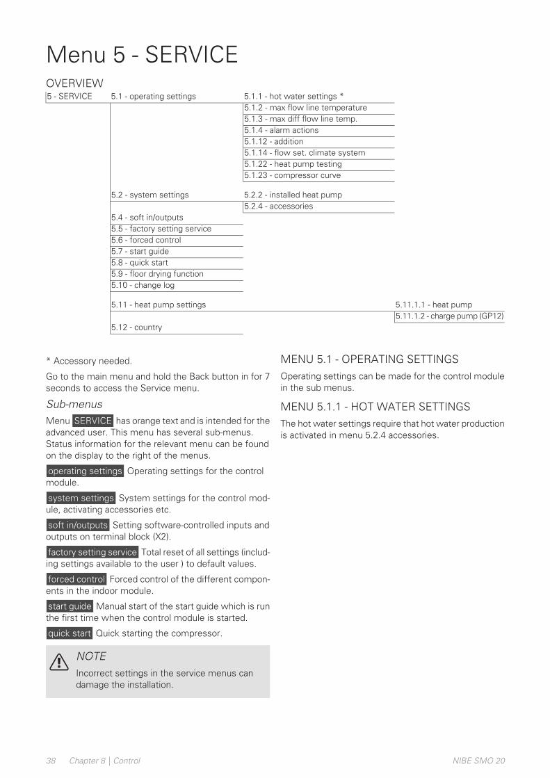
Menu 5 - SERVICEOVERVIEW
5.1.1 - hot water settings *5.1 - operating settings5 - SERVICE5.1.2 - max flow line temperature5.1.3 - max diff flow line temp.5.1.4 - alarm actions5.1.12 - addition5.1.14 - flow set. climate system5.1.22 - heat pump testing5.1.23 - compressor curve
5.2.2 - installed heat pump5.2 - system settings5.2.4 - accessories
5.4 - soft in/outputs5.5 - factory setting service5.6 - forced control5.7 - start guide5.8 - quick start5.9 - floor drying function5.10 - change log
5.11.1.1 - heat pump5.11 - heat pump settings5.11.1.2 - charge pump (GP12)
5.12 - country
* Accessory needed.
Go to the main menu and hold the Back button in for 7seconds to access the Service menu.
Sub-menusMenu SERVICE has orange text and is intended for theadvanced user. This menu has several sub-menus.Status information for the relevant menu can be foundon the display to the right of the menus.
operating settings Operating settings for the controlmodule.
system settings System settings for the control mod-ule, activating accessories etc.
soft in/outputs Setting software-controlled inputs andoutputs on terminal block (X2).
factory setting service Total reset of all settings (includ-ing settings available to the user ) to default values.
forced control Forced control of the different compon-ents in the indoor module.
start guide Manual start of the start guide which is runthe first time when the control module is started.
quick start Quick starting the compressor.
NOTEIncorrect settings in the service menus candamage the installation.
MENU 5.1 - OPERATING SETTINGSOperating settings can be made for the control modulein the sub menus.
MENU 5.1.1 - HOT WATER SETTINGSThe hot water settings require that hot water productionis activated in menu 5.2.4 accessories.
NIBE SMO 20Chapter 8 | Control38

economySetting range start temp. economy: 5 – 55 °C
Factory setting start temp. economy: 42 °C
Setting range stop temp. economy: 5 – 60 °C
Factory setting stop temp. economy: 48 °C
normalSetting range start temp. normal: 5 – 60 °C
Factory setting start temp. normal: 46 °C
Setting range stop temp. normal: 5 – 65 °C
Factory setting stop temp. normal: 50 °C
luxurySetting range start temp. lux: 5 – 70 °C
Factory setting start temp. lux: 49 °C
Setting range stop temp. lux: 5 – 70 °C
Factory setting stop temp. lux: 53 °C
stop temp. per. increaseSetting range: 55 – 70 °C
Factory setting: 55 °C
charge methodSetting range: target temp, delta temp
Default value: delta temp
Here you set the start and stop temperature of the hotwater for the different comfort options in menu 2.2 aswell as the stop temperature for periodic increase inmenu 2.9.1.
The charge method for hot water operation is selectedhere. “delta temp” is recommended for heaters withcharge coil, “target temp” for double-jacketed heatersand heaters with hot water coil.
MENU 5.1.2 - MAX FLOW LINETEMPERATURE
climate systemSetting range: 5-80 °C
Default value: 60 °C
Set the maximum supply temperature for the climatesystem here.
CautionUnderfloor heating systems are normally maxflow line temperature set between 35 and 45°C.
Check the max floor temperature with yourfloor supplier.
MENU 5.1.3 - MAX DIFF FLOW LINE TEMP.
max diff compressorSetting range: 1 – 25 °C
Default value: 10 °C
max diff additionSetting range: 1 – 24 °C
Default value: 7 °C
Here you set the maximum permitted differencebetween the calculated and actual supply temperatureduring compressor respectively add. heat mode. Maxdiff. additional heat can never exceed max diff. com-pressor
max diff compressorIf the current supply temperature exceeds the calculatedsupply by set value, the degree minute value is set to+2. The compressor in the heat pump stops if there isonly a heating demand.
max diff additionIf “addition” is selected and activated in menu 4.2 andthe current supply temperature exceeds the calculatedtemperature by the set value, the additional heat isforced to stop.
MENU 5.1.4 - ALARM ACTIONSSelect how you want the control module to alert youthat there is an alarm in the display here. The differentalternatives are; the heat pump stops producing hotwater and/or reduces the room temperature.
CautionIf no alarm action is selected, it can result inhigher energy consumption in the event of analarm.
MENU 5.1.12 - ADDITION
max stepSetting range (binary stepping deactivated): 0 – 3
Setting range (binary stepping activated): 0 – 7
Default value: 3
fuse sizeSetting range: 1 - 200 A
Factory setting: 16 A
Here you select whether the step controlled additionalheat is positioned before or after the reversing valve forhot water charging (QN10). Step controlled additionalheat is for example an external electric boiler.
39Chapter 8 | ControlNIBE SMO 20
Here you can set the max permitted number of addition-al heat steps and binary or linear stepping. When binarystepping is deactivated (off), the settings refer to linearstepping.
If accessory hot water is available and additional heatlocation is selected to "after QN10" the number of stepsare restricted to 2 steps linear or 3 steps binary. OutputAA7-X2:6 is reserved in this mode for additional heat inthe hot water tank.
You can also set the fuse size.
TIPSee the accessory installation instructions forfunction description.
MENU 5.1.14 - FLOW SET. CLIMATE SYSTEM
presettingsSetting range: radiator, floor heat., rad. + floor heat.,DOT °C
Default value: radiator
Setting range DOT: -40.0 – 20.0 °C
The factory setting of DOT value depends on thecountry that has been given for the product's location.The example below refers to Sweden.
Factory setting DOT: -20.0 °C
own settingSetting range dT at DOT: 0.0 – 25.0
Factory setting dT at DOT: 10.0
Setting range DOT: -40.0 – 20.0 °C
Factory setting DOT: -20.0 °C
The type of heating distribution system the heatingmedium pump works towards is set here.
dT at DOT is the difference in degrees between flowand return temperatures at dimensioned outdoor tem-perature.
MENU 5.1.22 - HEAT PUMP TESTING
NOTEThis menu is intended for testing SMO 20 ac-cording to different standards.
Use of this menu for other reasons may resultin your installation not functioning as intended.
This menu contains several sub-menus, one for eachstandard.
MENU 5.1.23 - COMPRESSOR CURVE
CautionThis menu is only displayed if SMO 20 is con-nected to a heat pump with inverter controlledcompressor.
Set whether the compressor in the heat pump shouldwork to a particular curve under specific requirementsor if it should work to predefined curves.
You set a curve for a demand (heat, hot water, coolingetc.) by unticking "auto", turning the control knob until atemperature is marked and pressing OK. You can nowset at what temperature max- respectively min frequen-cies will occur.
This menu can consist of several windows (one for eachavailable demand), use the navigation arrows in the topleft corner to change between the windows.
MENU 5.2 - SYSTEM SETTINGSMake different system settings for your installation here,e.g. activate the connected heat pump and which ac-cessories are installed.
MENU 5.2.2 - INSTALLED HEAT PUMPIf an air/water heat pump is connected to the controlmodule, you set it here.
MENU 5.2.4 - ACCESSORIESSet which accessories are installed on the installationhere.
If the water heater is connected to SMO 20 hot watercharging must be activated here.
MENU 5.4 - SOFT IN/OUTPUTSHere you can select which in/output on the terminalblock (X2) external switch function (page 25)
Selectable inputs on terminal blocks AUX 1-6 (X2:11-18and output AA2-X4.
MENU 5.5 - FACTORY SETTING SERVICEAll settings can be reset (including settings available tothe user) to default values here.
CautionWhen resetting, the start guide is displayedthe next time the control module is restarted.
MENU 5.6 - FORCED CONTROLYou can force control the different components in thecontrol module and any connected accessories here.
NIBE SMO 20Chapter 8 | Control40

MENU 5.7 - START GUIDEWhen the control module is started for the first time thestart guide starts automatically. Start it manually here.
See page 30 for more information about the start guide.
MENU 5.8 - QUICK STARTIt is possible to start the compressor from here.
CautionThere must be a heating, cooling or hot waterdemand to start the compressor.
NOTEDo not quick start the compressor too manytimes over a short period of time, as this coulddamage the compressor and its surroundingequipment.
MENU 5.9 - FLOOR DRYING FUNCTION
length of period 1 – 7Setting range: 0 – 30 days
Factory setting, period 1 – 3, 5 – 7: 2 days
Factory setting, period 4: 3 days
temp. period 1 – 7Setting range: 15 – 70 °C
Default value:
20 °Ctemp. period 130 °Ctemp. period 240 °Ctemp. period 345 Ctemp. period 440 °Ctemp. period 530 °Ctemp. period 620 °Ctemp. period 7
Set the function for under floor drying here.
You can set up to seven period times with differentcalculated flow temperatures. If less than seven periodsare to be used, set the remaining period times to 0 days.
Mark the active window to activate the underfloor dryingfunction. A counter at the bottom shows the number ofdays the function has been active.
TIPIf operating mode "add. heat only" is to be used,select it in menu 4.2.
TIPIt is possible to save a floor drying log thatshows when the concrete slab has reachedthe correct temperature. See section "Loggingfloor drying" on page 45.
MENU 5.10 - CHANGE LOGRead off any previous changes to the control systemhere.
The date, time and ID no. (unique to certain settings)and the new set value is shown for every change.
CautionThe change log is saved at restart and remainsunchanged after factory setting.
MENU 5.11 - HEAT PUMP SETTINGSSettings for installed heat pump can be made in thesubmenus.
MENU 5.11.1.1 - HEAT PUMPMake settings for the installed heat pump here. To seewhat settings you can make, see installation manual forthe heat pump.
41Chapter 8 | ControlNIBE SMO 20
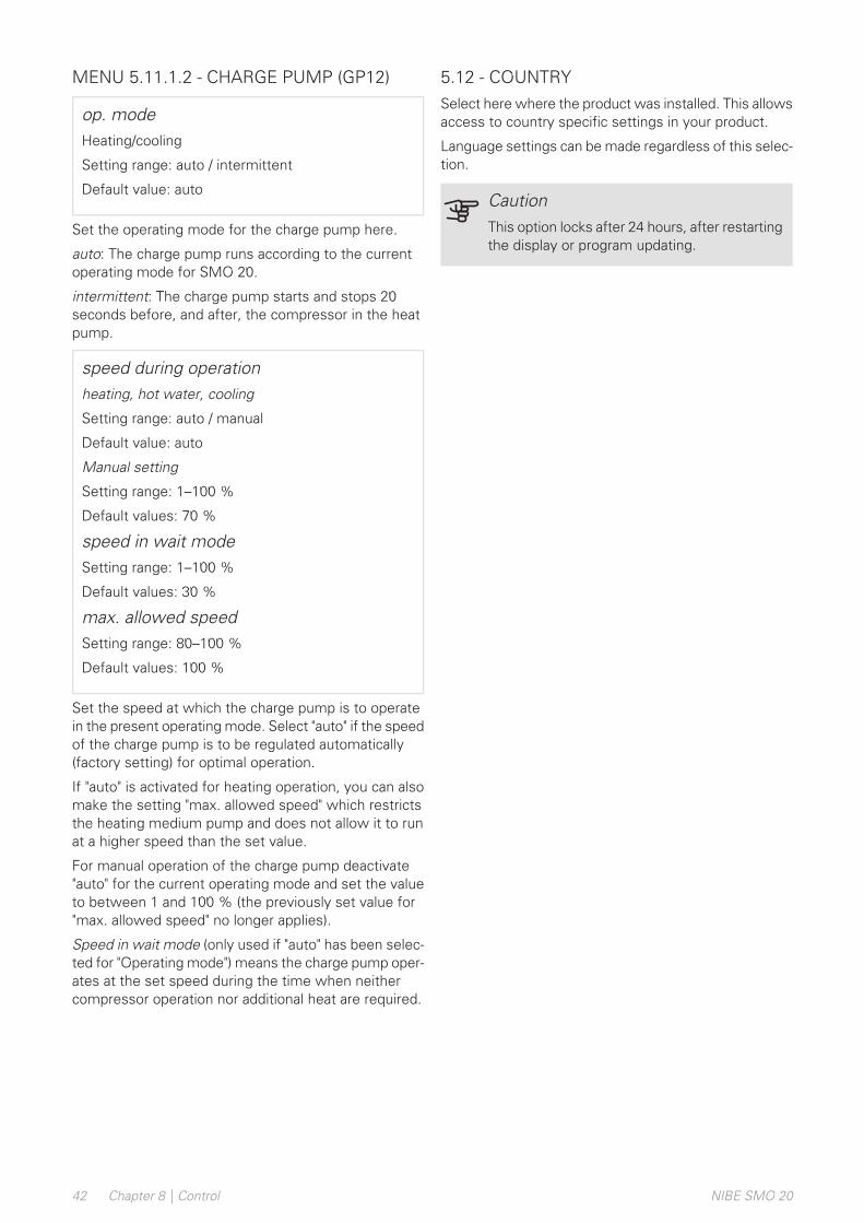
MENU 5.11.1.2 - CHARGE PUMP (GP12)
op. modeHeating/cooling
Setting range: auto / intermittent
Default value: auto
Set the operating mode for the charge pump here.
auto: The charge pump runs according to the currentoperating mode for SMO 20.
intermittent: The charge pump starts and stops 20seconds before, and after, the compressor in the heatpump.
speed during operationheating, hot water, cooling
Setting range: auto / manual
Default value: auto
Manual setting
Setting range: 1–100 %
Default values: 70 %
speed in wait modeSetting range: 1–100 %
Default values: 30 %
max. allowed speedSetting range: 80–100 %
Default values: 100 %
Set the speed at which the charge pump is to operatein the present operating mode. Select "auto" if the speedof the charge pump is to be regulated automatically(factory setting) for optimal operation.
If "auto" is activated for heating operation, you can alsomake the setting "max. allowed speed" which restrictsthe heating medium pump and does not allow it to runat a higher speed than the set value.
For manual operation of the charge pump deactivate"auto" for the current operating mode and set the valueto between 1 and 100 % (the previously set value for"max. allowed speed" no longer applies).
Speed in wait mode (only used if "auto" has been selec-ted for "Operating mode") means the charge pump oper-ates at the set speed during the time when neithercompressor operation nor additional heat are required.
5.12 - COUNTRYSelect here where the product was installed. This allowsaccess to country specific settings in your product.
Language settings can be made regardless of this selec-tion.
CautionThis option locks after 24 hours, after restartingthe display or program updating.
NIBE SMO 20Chapter 8 | Control42

Service actionsNOTEServicing should only be carried out by personswith the necessary expertise.
When replacing components on SMO 20 onlyreplacement parts from NIBE may be used.
EMERGENCY MODE
NOTESwitch (SF1) must not be put into mode "" or
before the installation is filled with water.The compressor in the heat pump can bedamaged.
Emergency mode is used in event of operational inter-ference and in conjunction with service. Hot water isnot produced in emergency mode.
Emergency mode is activated by setting switch (SF1)in mode " ". This means that:
• The status lamp illuminates yellow.
• The display is not lit and the control computer is notconnected.
• Hot water is not produced.
• The compressor in the heat pump is switched off.Charge pump (EB101-GP12) is running.
• The heating medium pump is active.
• The emergency mode relay (K2) is active.
External additional heat is active if it is connected to theemergency mode relay (K2, terminal block X1). Ensurethat the heating medium circulates through the externaladditional heat.
TEMPERATURE SENSOR DATA
Voltage (VDC)Resistance (kOhm)Temperature (°C)
3.256351.0-403.240251.6-353.218182.5-303.189133.8-253.15099.22-203.10574.32-153.04756.20-102.97642.89-52.88933.0202.78925.6152.67320.02102.54115.77152.39912.51202.24510.00252.0838.045301.9166.514351.7525.306401.5874.348451.4263.583501.2782.968551.1362.467601.0072.068650.8911.739700.7851.469750.6911.246800.6071.061850.5330.908900.4690.779950.4140.672100
43Chapter 9 | ServiceNIBE SMO 20
9 Service
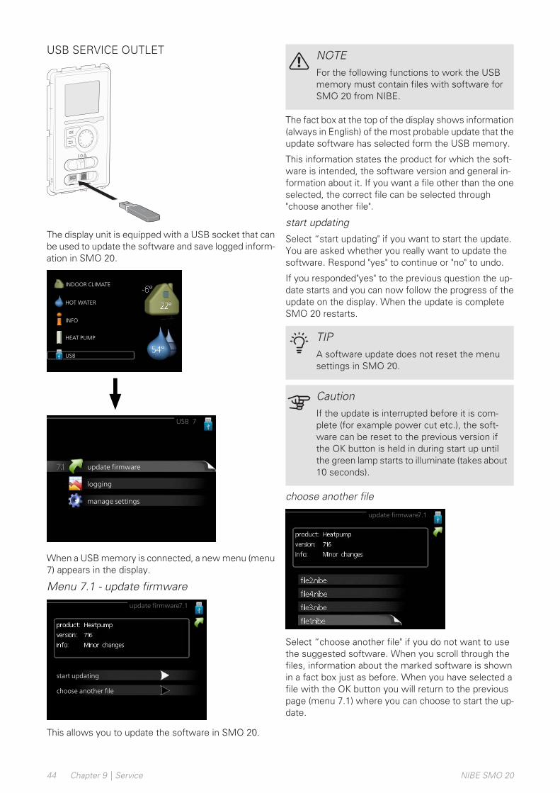
USB SERVICE OUTLET
LEK
The display unit is equipped with a USB socket that canbe used to update the software and save logged inform-ation in SMO 20.
INDOOR CLIMATE
HOTWATER
INFO
HEAT PUMP
USB
update firmware
USB 7
logging
manage settings
When a USB memory is connected, a new menu (menu7) appears in the display.
Menu 7.1 - update firmware
update firmware7.1
start updating
choose another file
This allows you to update the software in SMO 20.
NOTEFor the following functions to work the USBmemory must contain files with software forSMO 20 from NIBE.
The fact box at the top of the display shows information(always in English) of the most probable update that theupdate software has selected form the USB memory.
This information states the product for which the soft-ware is intended, the software version and general in-formation about it. If you want a file other than the oneselected, the correct file can be selected through"choose another file".
start updating
Select “start updating" if you want to start the update.You are asked whether you really want to update thesoftware. Respond "yes" to continue or "no" to undo.
If you responded"yes" to the previous question the up-date starts and you can now follow the progress of theupdate on the display. When the update is completeSMO 20 restarts.
TIPA software update does not reset the menusettings in SMO 20.
CautionIf the update is interrupted before it is com-plete (for example power cut etc.), the soft-ware can be reset to the previous version ifthe OK button is held in during start up untilthe green lamp starts to illuminate (takes about10 seconds).
choose another file
update firmware7.1
Select “choose another file" if you do not want to usethe suggested software. When you scroll through thefiles, information about the marked software is shownin a fact box just as before. When you have selected afile with the OK button you will return to the previouspage (menu 7.1) where you can choose to start the up-date.
NIBE SMO 20Chapter 9 | Service44
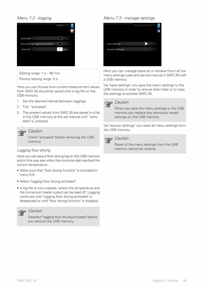
Menu 7.2 - logging
logging 7.2
activated
interval sec5
floor drying logging activated
Setting range: 1 s – 60 min
Factory setting range: 5 s
Here you can choose how current measurement valuesfrom SMO 20 should be saved onto a log file on theUSB memory.
1. Set the desired interval between loggings.
2. Tick “activated".
3. The present values from SMO 20 are saved in a filein the USB memory at the set interval until “activ-ated" is unticked.
CautionUntick "activated" before removing the USBmemory.
Logging floor drying
Here you can save a floor drying log on the USB memoryand in this way see when the concrete slab reached thecorrect temperature.
• Make sure that "floor drying function" is activated inmenu 5.9.
• Select "logging floor drying activated".
• A log file is now created, where the temperature andthe immersion heater output can be read off. Loggingcontinues until "logging floor drying activated" isdeselected or until "floor drying function" is stopped.
CautionDeselect "logging floor drying activated" beforeyou remove the USB memory.
Menu 7.3 - manage settings
manage settings 7.3
save settings
recover settings
Here you can manage (save as or retrieve from) all themenu settings (user and service menus) in SMO 20 witha USB memory.
Via "save settings" you save the menu settings to theUSB memory in order to restore them later or to copythe settings to another SMO 20.
CautionWhen you save the menu settings to the USBmemory you replace any previously savedsettings on the USB memory.
Via "recover settings" you reset all menu settings fromthe USB memory.
CautionReset of the menu settings from the USBmemory cannot be undone.
45Chapter 9 | ServiceNIBE SMO 20

In most cases, SMO 20 notes a malfunction (a malfunc-tion can lead to disruption in comfort) and indicates thiswith alarms, and instructions for action, in the display.
Info-menuAll the installation’s measurement values are gatheredunder menu 3.1 in the control module’s menu system.Examining the values in this menu can often make iteasier to identify the source of the fault.
Manage alarm
info / action
reset alarm
aid mode
Low pressure alarm
alarm
In the event of an alarm, some kind of malfunction hasoccurred, which is indicated by the status lamp changingfrom green continuously to red continuously. In addition,an alarm bell appears in the information window.
ALARMIn the event of an alarm with a red status lamp a mal-function has occurred that the heat pump and/or controlmodule cannot remedy itself. In the display, by turningthe control knob and pressing the OK button, you cansee the type of alarm it is and reset it. You can alsochoose to set the installation to aid mode.
info / action Here you can read what the alarm meansand receive tips on what you can do to correct theproblem that caused the alarm.
reset alarm In many cases, it is sufficient to select “resetalarm” for the product to revert to normal operation. Ifa green light comes on after selecting “reset alarm”,the alarm has been remedied. If the red light is still on,and a menu called “alarm” is visible in the display, theproblem causing the alarm still remains.
aid mode “aid mode” is a type of emergency mode.This means that the installation produces heat and/orhot water even if there is some kind of problem. Thiscould mean that the heat pump’s compressor is not inoperation. In this case, any electric additional heat pro-duces heat and/or hot water.
CautionTo select aid mode an alarm action must beselected in the menu 5.1.4.
CautionSelecting "aid mode” is not the same as cor-recting the problem that caused the alarm. Thestatus lamp will therefore continue to be red.
If the operational interference is not shown in the displaythe following tips can be used:
BASIC ACTIONSStart by checking the following items:
• The switch's (SF1) position.
• Group and main fuses of the accommodation.
• Miniature circuit breaker for SMO 20 (FA1).
• The property's earth circuit breaker.
NIBE SMO 20Chapter 10 | Disturbances in comfort46
10 Disturbances in comfort
LOW HOT WATER TEMPERATURE OR ALACK OF HOT WATERThis part of the fault-tracing chapter only applies if thewater heater is installed in the system.
• Closed or choked filling valve for the hot water.
– Open the valve.
• Mixing valve (if there is one installed) set too low.
– Adjust the mixer valve.
• SMO 20 in incorrect operating mode.
– Enter menu 4.2. If mode "auto" is selected, select ahigher value on "stop additional heat" in menu 4.9.2.
– If mode "manual" is selected, select "addition".
• Large hot water consumption.
– Wait until the hot water has heated up. Temporarilyincreased hot water capacity (temporary lux) can beactivated in menu 2.1.
• Too low hot water setting.
– Enter menu 2.2 and select a higher comfort mode.
• Low hot water access with the “Smart Control”function active.
– If the hot water usage has been low, the installationwill produce less hot water than normal. Restart theinstallation
• Too low or no operating prioritisation of hot water.
– Enter menu 4.9.1 and increase the time for whenhot water is to be prioritised. Note that if the timefor hot water is increased, the time for heating pro-duction is reduced, which can give lower/unevenroom temperatures.
• "Holiday mode" activated in menu 4.7.
– Enter menu 4.7 and select "Off".
LOW ROOM TEMPERATURE• Closed thermostats in several rooms.
– Set the thermostats to max, in as many rooms aspossible. Adjust the room temperature via menu1.1, instead of choking the thermostats.
• SMO 20 in incorrect operating mode.
– Enter menu 4.2. If mode "auto" is selected, select ahigher value on "stop heating" in menu 4.9.2.
– If mode "manual" is selected, select "heating". If thisis not enough, select "addition".
• Too low set value on the automatic heating control.
– Enter menu 1.1 "temperature" and adjust the offsetheating curve up. If the room temperature is onlylow in cold weather the curve slope in menu 1.9.1"heating curve" needs adjusting up.
• Too low or no operating prioritisation of heat.
– Enter menu 4.9.1 and increase the time for whenheating is to be prioritised. Note that if the time forheating is increased the time for hot water produc-tion is reduced, which can give smaller amounts ofhot water.
• "Holiday mode" activated in menu 4.7.
– Enter menu 4.7 and select "Off".
• External switch for changing the room heating activ-ated.
– Check any external switches.
• Air in the climate system.
– Vent the climate system.
• Closed valves to the climate system or heat pump.
– Open the valves.
HIGH ROOM TEMPERATURE• Too high set value on the automatic heating control.
– Enter menu 1.1 (temperature) and reduce the offsetheating curve. If the room temperature is only highin cold weather the curve slope in menu 1.9.1"heating curve" needs adjusting down.
• External switch for changing the room heating activ-ated.
– Check any external switches.
LOW SYSTEM PRESSURE• Not enough water in the climate system.
– Fill the climate system with water and check forleaks. In event of repeated filling, contact the in-staller.
THE AIR/WATER HEAT PUMP’SCOMPRESSOR DOES NOT START• There is no heating requirement.
– SMO 20 does not call on heating or hot water.
• Compressor blocked due to the temperature condi-tions.
– Wait until the temperature is within the product’sworking range.
• Minimum time between compressor starts has notbeen reached.
– Wait for at least 30 minutes and then check if thecompressor has started.
• Alarm tripped.
– Follow the display instructions.
47Chapter 10 | Disturbances in comfortNIBE SMO 20

Additional heating onlyIf you are unsuccessful in rectifying the fault and areunable to heat the house, you can, whilst waiting forassistance, continue running the heat pump in ”add.heat only”. This means that additional heating only isused to heat the house.
SET THE INSTALLATION TO ADDITIONALHEAT MODE1. Go to menu 4.2 op. mode.
2. Mark ”add. heat only” using the control knob andthen press the OK button.
3. Return to the main menus by pressing the Backbutton.
CautionWhen commissioning without NIBE air/waterheat pump, the "communication error" alarmmay appear in the display.
The alarm is reset if the relevant air/water heatpump is deactivated in menu 5.2.2 ("installedheat pump").
NIBE SMO 20Chapter 10 | Disturbances in comfort48
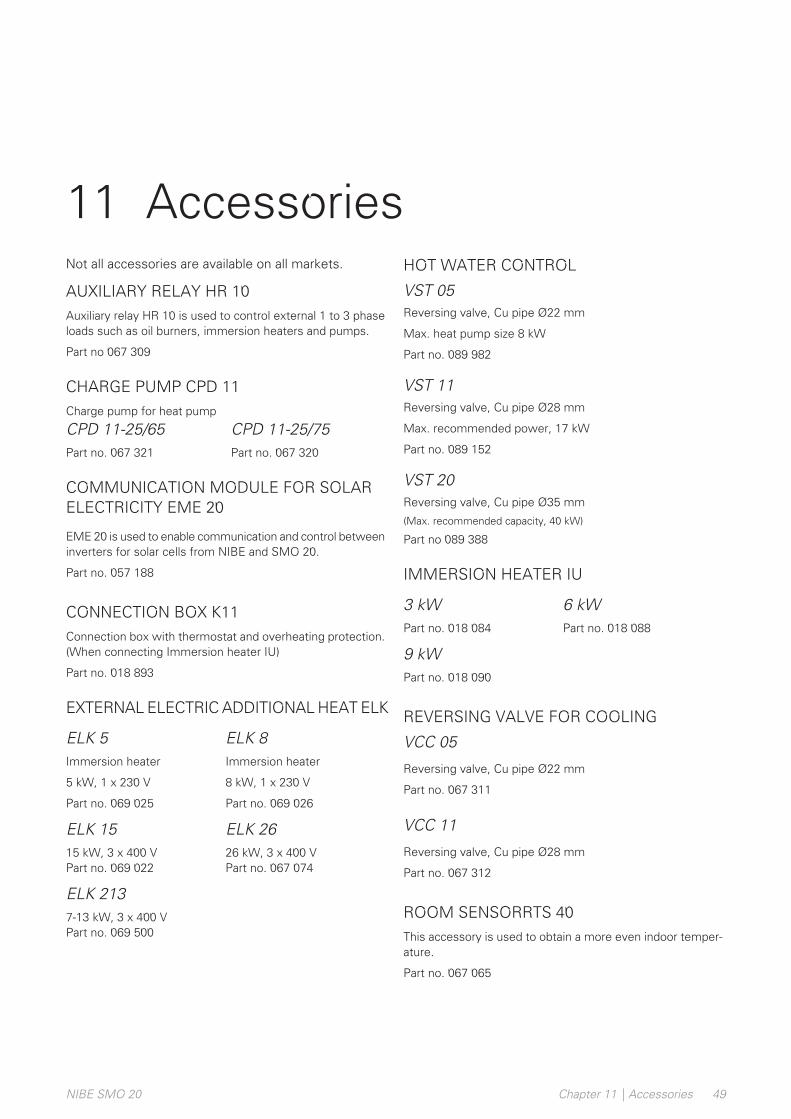
Not all accessories are available on all markets.
AUXILIARY RELAY HR 10Auxiliary relay HR 10 is used to control external 1 to 3 phaseloads such as oil burners, immersion heaters and pumps.
Part no 067 309
CHARGE PUMP CPD 11Charge pump for heat pump
CPD 11-25/75Part no. 067 320
CPD 11-25/65Part no. 067 321
COMMUNICATION MODULE FOR SOLARELECTRICITY EME 20
EME 20 is used to enable communication and control betweeninverters for solar cells from NIBE and SMO 20.
Part no. 057 188
CONNECTION BOX K11Connection box with thermostat and overheating protection.(When connecting Immersion heater IU)
Part no. 018 893
EXTERNAL ELECTRIC ADDITIONAL HEAT ELK
ELK 8Immersion heater
8 kW, 1 x 230 V
Part no. 069 026
ELK 5Immersion heater
5 kW, 1 x 230 V
Part no. 069 025
ELK 2626 kW, 3 x 400 VPart no. 067 074
ELK 1515 kW, 3 x 400 VPart no. 069 022
ELK 2137-13 kW, 3 x 400 VPart no. 069 500
HOT WATER CONTROL
VST 05Reversing valve, Cu pipe Ø22 mm
Max. heat pump size 8 kW
Part no. 089 982
VST 11Reversing valve, Cu pipe Ø28 mm
Max. recommended power, 17 kW
Part no. 089 152
VST 20Reversing valve, Cu pipe Ø35 mm
(Max. recommended capacity, 40 kW)
Part no 089 388
IMMERSION HEATER IU
6 kWPart no. 018 088
3 kWPart no. 018 084
9 kWPart no. 018 090
REVERSING VALVE FOR COOLING
VCC 05
Reversing valve, Cu pipe Ø22 mm
Part no. 067 311
VCC 11
Reversing valve, Cu pipe Ø28 mm
Part no. 067 312
ROOM SENSORRTS 40This accessory is used to obtain a more even indoor temper-ature.
Part no. 067 065
49Chapter 11 | AccessoriesNIBE SMO 20
11 Accessories
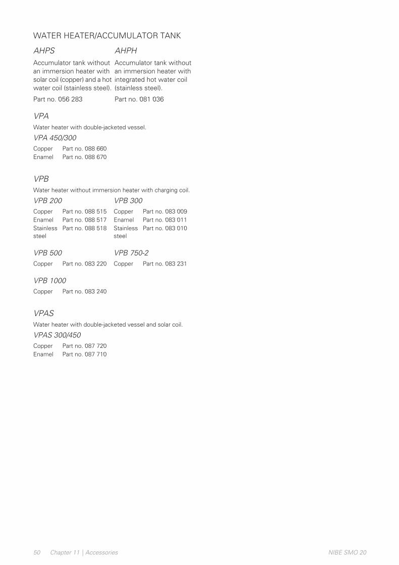
WATER HEATER/ACCUMULATOR TANK
AHPHAccumulator tank withoutan immersion heater withintegrated hot water coil(stainless steel).
Part no. 081 036
AHPSAccumulator tank withoutan immersion heater withsolar coil (copper) and a hotwater coil (stainless steel).
Part no. 056 283
VPAWater heater with double-jacketed vessel.
VPA 450/300Part no. 088 660CopperPart no. 088 670Enamel
VPBWater heater without immersion heater with charging coil.
VPB 300VPB 200Part no. 083 009CopperPart no. 088 515CopperPart no. 083 011EnamelPart no. 088 517EnamelPart no. 083 010Stainless
steelPart no. 088 518Stainless
steel
VPB 750-2VPB 500Part no. 083 231CopperPart no. 083 220Copper
VPB 1000Part no. 083 240Copper
VPASWater heater with double-jacketed vessel and solar coil.
VPAS 300/450Part no. 087 720CopperPart no. 087 710Enamel
NIBE SMO 20Chapter 11 | Accessories50

Dimensions
110
410
360
110
10
310
2157035
51Chapter 12 | Technical dataNIBE SMO 20
12 Technical data
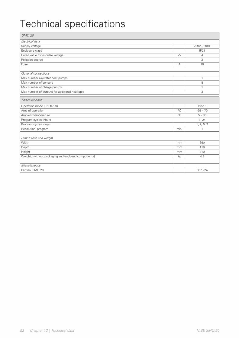
Technical specificationsSMO 20
Electrical data230V~ 50HzSupply voltage
IP21Enclosure class
4kVRated value for impulse voltage
2Pollution degree
10AFuse
Optional connections1Max number air/water heat pumps
8Max number of sensors
1Max number of charge pumps
3Max number of outputs for additional heat step
Miscellaneous
Type 1Operation mode (EN60730)
-25 – 70°CArea of operation
5 – 35°CAmbient temperature
1, 24Program cycles, hours
1, 2, 5, 7Program cycles, days
1min.Resolution, program
Dimensions and weight360mmWidth
110mmDepth
410mmHeight
4.3kgWeight, (without packaging and enclosed components)
Miscellaneous067 224Part no. SMO 20
NIBE SMO 20Chapter 12 | Technical data52

Energy labellingNIBESupplier
SMO 20 + F2040 / F2120Model
IIController, class
2.0%Controller, contribution to efficiency
53Chapter 12 | Technical dataNIBE SMO 20

Electrical circuit diagramPart Specification Sheet 051065-5
Page 2/5 Created:2017-06-30 16:16
0.00
1
ASN
2017
-06-
30
Prod
uctio
nM
JN20
12-1
0-02
WIR
ING
DIAG
RAM
SM
O20
KRET
SSCH
EMA
SMO2
005
1065
5
NIBE SMO 20Chapter 12 | Technical data54

Part Specification Sheet 051065-5Page 3/5 Created:2017-06-30 16:16
0.00
1
ASN
2017
-06-
30
Prod
uctio
nM
JN20
12-1
0-02
WIR
ING
DIAG
RAM
SM
O20
KRET
SSCH
EMA
SMO2
005
1065
5
55Chapter 12 | Technical dataNIBE SMO 20

Part Specification Sheet 051065-5Page 4/5 Created:2017-06-30 16:16
0.00
1
ASN
2017
-06-
30
Prod
uctio
nM
JN20
12-1
0-02
WIR
ING
DIAG
RAM
SM
O20
KRET
SSCH
EMA
SMO2
005
1065
5
NIBE SMO 20Chapter 12 | Technical data56
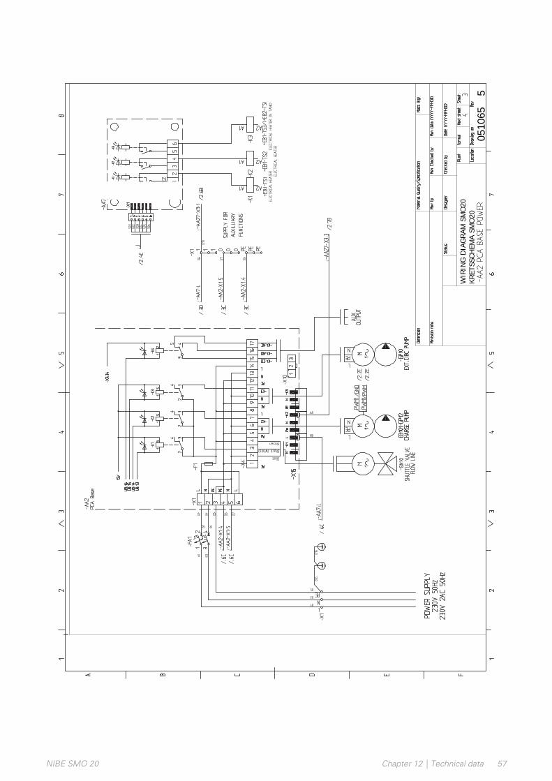
Part Specification Sheet 051065-5Page 4/5 Created:2017-06-30 16:16
0.00
1
ASN
2017
-06-
30
Prod
uctio
nM
JN20
12-1
0-02
WIR
ING
DIAG
RAM
SM
O20
KRET
SSCH
EMA
SMO2
005
1065
5
57Chapter 12 | Technical dataNIBE SMO 20
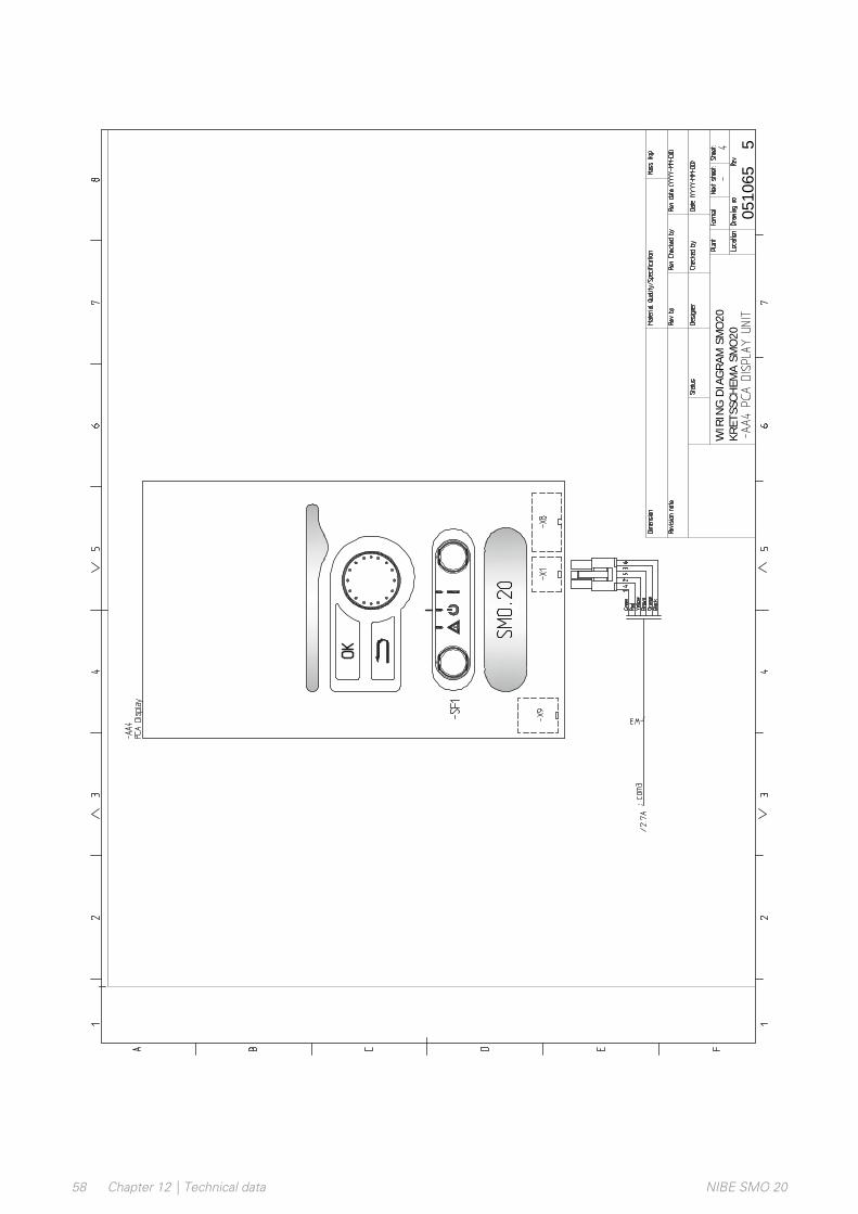
Part Specification Sheet 051065-5Page 5/5 Created:2017-06-30 16:16
0.00
1
ASN
2017
-06-
30
Prod
uctio
nM
JN20
12-1
0-02
WIR
ING
DIAG
RAM
SM
O20
KRET
SSCH
EMA
SMO2
005
1065
5
NIBE SMO 20Chapter 12 | Technical data58

59Chapter 12 | Technical dataNIBE SMO 20

A
Accessibility, electrical connection, 18Accessories, 49Alarm, 46
B
Back button, 31
C
Cable lock, 19Commissioning and adjusting, 29
Commissioning with additional heating only, 29Commissioning with NIBE air/water heat pump, 29Cooling mode, 29Preparations, 29Start guide, 30
Commissioning with additional heating only, 29Commissioning with NIBE air/water heat pump, 29Communication with heat pump, 21Connecting accessories, 28Connecting the charge pump for the heat pump, 20Connections, 20Control, 31, 35
Control - Introduction, 31Control - Menus, 35
Control - Introduction, 31Display unit, 31Menu system, 32
Control knob, 31Control - Menus, 35
Menu 5 - SERVICE, 38Cooling mode, 29Cooling mode indication, 26
D
Delivery and handling, 9Mounting, 9Supplied components, 9
Dimensions and setting-out coordinates, 51Display, 31Display unit, 31
Back button, 31Control knob, 31Display, 31OK button, 31Status lamp, 31Switch, 31
Disturbances in comfort, 46Alarm, 46
Manage alarm, 46Only additional heat, 48Troubleshooting, 46
Docking alternatives, 13
E
Electrical circuit diagram, 54Electrical connections, 17
Accessibility, electrical connection, 18Cable lock, 19Communication with heat pump, 21Connecting accessories, 28Connecting the charge pump for the heat pump, 20Connections, 20External circulation pump, 25External connection options (AUX), 25General, 17Miniature circuit-breaker, 17NIBE Uplink, 25Optional connections, 24Outdoor sensor, 22Power connection, 20Relay output for emergency mode, 24Reversing valve, 25Room sensor, 22Step controlled additional heat, 24Temperature sensor, external flow line, 23Temperature sensor, external supply line after electricheater, 23Temperature sensor, hot water charging, 23
Energy labelling, 53External circulation pump, 25External connection options
Possible selections for AUX output, 26Temperature sensor, hot water top, 23
External connection options (AUX), 25Cooling mode indication, 26Extra circulation pump, 26Hot water circulation, 26Optional selection for AUX output (potential-freevariable relay), 26
Extra circulation pump, 26
H
Help menu, 30, 34Hot water circulation, 26
NIBE SMO 20Item register60
Item register
I
Important information, 4Inspection of the installation, 6Marking, 4Recovery, 5Safety information, 4Serial number, 5Symbols, 4System solutions, 7
Inspection of the installation, 6
M
Manage alarm, 46Marking, 4Menu 5 - SERVICE, 38Menu system, 32
Help menu, 30, 34Operation, 33Scroll through the windows, 34Selecting menu, 33Selecting options, 33Setting a value, 33Use the virtual keyboard, 34
Miniature circuit-breaker, 17Mounting, 9
N
NIBE Uplink, 25
O
OK button, 31Only additional heat, 48Operation, 33Optional connections, 24
Possible selections for AUX inputs, 25Outdoor sensor, 22
P
Pipe connections, 11Docking alternatives, 13General, 11Symbol key, 12
Possible selection for AUX inputs, 25Possible selection for AUX output (potential free variablerelay), 26Possible selections for AUX output, 26Power connection, 20Preparations, 29
R
Recovery, 5Relay output for emergency mode, 24Reversing valve, 25Room sensor, 22
S
Safety information, 4Marking, 4Serial number, 5Symbols on SMO 20, 4
Scroll through the windows, 34Selecting menu, 33
Selecting options, 33Serial number, 5Service, 43
Service actions, 43Service actions, 43
Standby mode, 43Temperature sensor data, 43USB service outlet, 44
Setting a value, 33Standby mode, 43Start guide, 30Status lamp, 31Step controlled additional heat, 24Supplied components, 9Switch, 31Symbol key, 12Symbols, 4Symbols on SMO 20, 4System solutions, 7
T
Technical data, 51Dimensions and setting-out coordinates, 51Electrical circuit diagram, 54
Temperature sensor, external flow line, 23Temperature sensor, external supply line after electricheater, 23Temperature sensor, hot water charging, 23Temperature sensor, hot water top, 23Temperature sensor data, 43The Control Module Design, 10
Component locations, 10List of components, 10
Troubleshooting, 46
U
USB service outlet, 44Use the virtual keyboard, 34
61Item registerNIBE SMO 20


Contact informationDENMARKCZECH REPUBLICAUSTRIA
Vølund Varmeteknik A/SIndustrivej Nord 7B, 7400 HerningTel: +45 97 17 20 [email protected]
Družstevní závody Dražice - strojírnas.r.o.Dražice 69, 29471 Benátky n. Jiz.Tel: +420 326 373 [email protected]
KNV Energietechnik GmbHGahberggasse 11, 4861 SchörflingTel: +43 (0)7662 [email protected]
GERMANYFRANCEFINLAND
NIBE Systemtechnik GmbHAm Reiherpfahl 3, 29223 CelleTel: +49 (0)5141 75 46 [email protected]
NIBE Energy Systems France SASZone industrielle RD 28Rue du Pou du Ciel, 01600 ReyrieuxTél: 04 74 00 92 [email protected]
NIBE Energy Systems OyJuurakkotie 3, 01510 VantaaTel: +358 (0)9 274 [email protected]
NORWAYNETHERLANDSGREAT BRITAIN
ABK ASBrobekkveien 80, 0582 OsloTel: (+47) 23 17 05 [email protected]
NIBE Energietechniek B.V.Energieweg 31, 4906 CG OosterhoutTel: +31 (0)168 47 77 [email protected]
NIBE Energy Systems Ltd3C Broom Business Park,Bridge Way, S41 9QG ChesterfieldTel: +44 (0)845 095 [email protected]
SWEDENRUSSIAPOLAND
NIBE Energy SystemsBox 14Hannabadsvägen 5, 285 21 MarkarydTel: +46 (0)433-27 [email protected]
EVANbld. 8, Yuliusa Fuchika str.603024 Nizhny NovgorodTel: +7 831 419 57 [email protected]
NIBE-BIAWAR Sp. z o.o.Al. Jana Pawla II 57, 15-703 BialystokTel: +48 (0)85 66 28 490biawar.com.pl
SWITZERLAND
NIBE Wärmetechnik c/o ait SchweizAGIndustriepark, CH-6246 AltishofenTel. +41 (0)58 252 21 [email protected]
For countries not mentioned in this list, contact NIBE Sweden or check nibe.eu for more information.

NIBE Energy SystemsHannabadsvägen 5Box 14SE-285 21 [email protected]
IHB
EN
191
8-8
2317
58
This manual is a publication from NIBE Energy Systems. All product illustrations, facts anddata are based on the available information at the time of the publication’s approval.NIBE Energy Systems makes reservations for any factual or printing errors in this manual.
©2019 NIBE ENERGY SYSTEMS 231758
WS name: -GemensamtWS version: a637WS release date: 2019-03-21 09:55Publish date: 2019-05-27 14:13


