114
Installation and User Instructions Wireless discussion system en DCN Wireless
Installation and User Instructions
Wireless discussion systemen
DCN Wireless

Bosch Security Systems | 2007-11 | 9922 141 70691 en
DCN Wireless | Installation and User Instructions | Important Safeguards en | 3
Important Safeguards
Before you install or operate the DCN Wireless digital congress network, you must read the Important Safety Instructions. The Important Safety Instructions are supplied together with the central control unit.

Bosch Security Systems | 2007-11 | 9922 141 70691 en
DCN Wireless | Installation and User Instructions | Disclaimers en | 4
Disclaimers
CobraNet is a trademark of Peak Audio — a division of Cirrus Logic, Inc. — in the United States and/or other countries.
Bosch Security Systems | 2007-11 | 9922 141 70691 en
DCN Wireless | Installation and User Instructions | About this manual en | 5
About this manual
FunctionThe Installation and User Instructions gives the installers and the operators the necessary data to install, configure and operate a basic DCN Wireless Discussion System.
When you want to make a more advanced DCN Wireless Discussion System, you also need information from the DCN Next Generation Installation and User Instructions.
The product index (refer to appendix B) tells you where you can find more data about devices that can be connected to DCN Wireless.
Digital versionThe Installation and User Instructions is available as a digital file (Portable Document File, PDF).When the PDF refers you to a location that contains more data, you can click the text to go there. The text contains hyperlinks.
Admonitions and notesThe Installation and User Instructions uses admonitions and notes. The admonition gives the effect if you do not obey the instructions. These are the types:• Caution
If you do not obey the caution, you can cause damage to the equipment.
• WarningIf you do not obey the warning, you can cause personal injury or death.
SignsThe Installation and User Instructions shows each admonition with a sign. The sign shows the effect if you do not obey the instruction.
The sign that is shown along with a note gives more data about the note itself.
AdmonitionGeneral sign for cautions and warnings.
AdmonitionRisk of electric shock.
AdmonitionRisk of electro-static discharges (refer to the section ’Electro-static discharges’).
NoteGeneral sign for notes.
NoteRefer to another information source.
Bosch Security Systems | 2007-11 | 9922 141 70691 en
DCN Wireless | Installation and User Instructions | About this manual en | 6
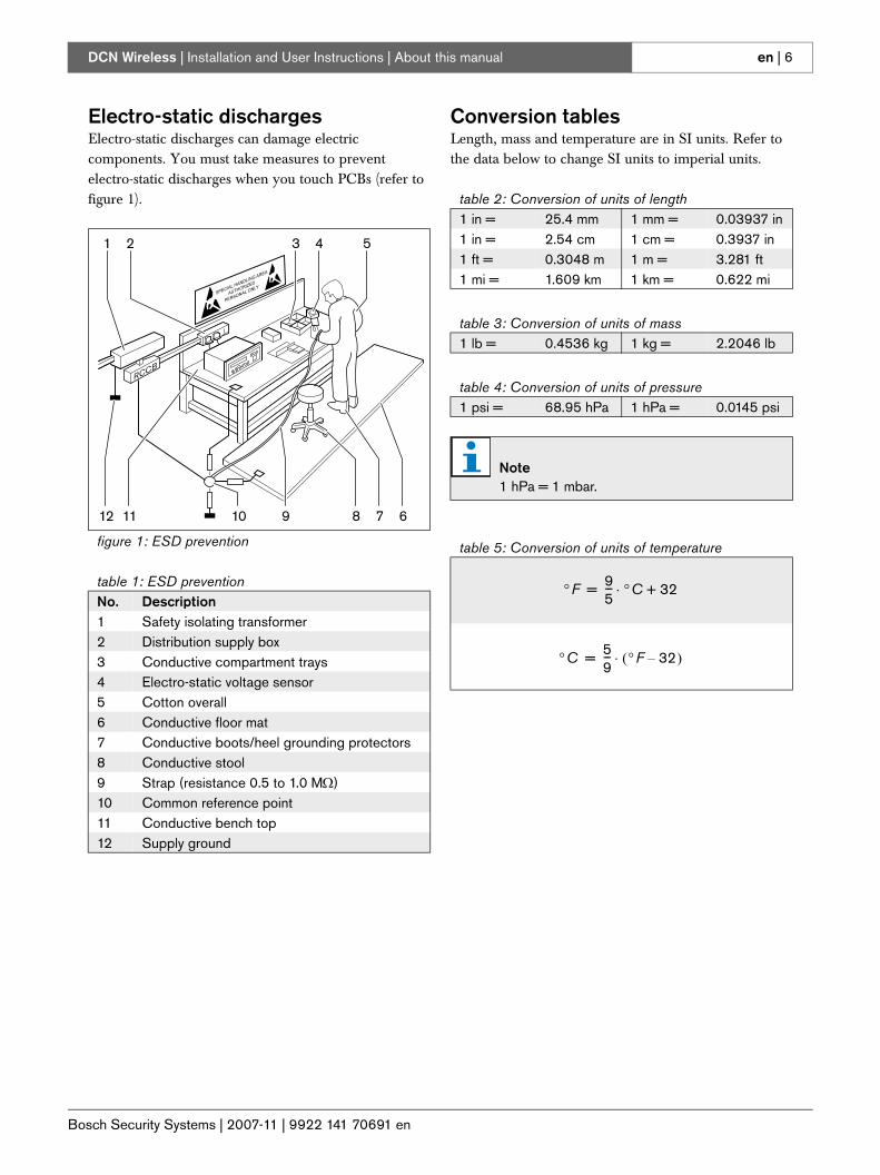
Electro-static dischargesElectro-static discharges can damage electric components. You must take measures to prevent electro-static discharges when you touch PCBs (refer to figure 1).
Conversion tablesLength, mass and temperature are in SI units. Refer to the data below to change SI units to imperial units.
figure 1: ESD prevention
table 1: ESD preventionNo. Description1 Safety isolating transformer2 Distribution supply box3 Conductive compartment trays4 Electro-static voltage sensor5 Cotton overall6 Conductive floor mat7 Conductive boots/heel grounding protectors8 Conductive stool9 Strap (resistance 0.5 to 1.0 MΩ)10 Common reference point11 Conductive bench top12 Supply ground
31 2
12 11 10 9 8 7 6
4 5
table 2: Conversion of units of length1 in = 25.4 mm 1 mm = 0.03937 in1 in = 2.54 cm 1 cm = 0.3937 in1 ft = 0.3048 m 1 m = 3.281 ft1 mi = 1.609 km 1 km = 0.622 mi
table 3: Conversion of units of mass1 lb = 0.4536 kg 1 kg = 2.2046 lb
table 4: Conversion of units of pressure1 psi = 68.95 hPa 1 hPa = 0.0145 psi
Note1 hPa = 1 mbar.
table 5: Conversion of units of temperature
°F 95--- °C 32+⋅=
°C 59--- °F 32( )⋅=
Bosch Security Systems | 2007-11 | 9922 141 70691 en
DCN Wireless | Installation and User Instructions | Table of Contents en | 7
Table of Contents
Important Safeguards ..................................................................................................................................................3Disclaimers ......................................................................................................................................................................4About this manual .........................................................................................................................................................5Table of Contents ..........................................................................................................................................................7Section 1 - System Design and Planning............................................................................................................. 11
1. Wireless network design ........................................................................................................................................................... 121.1 Introduction ............................................................................................................................................................................ 121.2 Limits ....................................................................................................................................................................................... 121.3 Frequency band .................................................................................................................................................................... 13
2. DCN design .................................................................................................................................................................................. 152.1 Introduction ............................................................................................................................................................................ 152.2 Limits ....................................................................................................................................................................................... 15
3. Optical network design .............................................................................................................................................................. 163.1 Introduction ............................................................................................................................................................................ 163.2 Calculation tool ..................................................................................................................................................................... 163.3 Limits ....................................................................................................................................................................................... 163.4 Control capacity ................................................................................................................................................................... 163.5 Power capacity ..................................................................................................................................................................... 163.6 Cabling ................................................................................................................................................................................... 173.7 Example layouts .................................................................................................................................................................... 19
4. Camera control ............................................................................................................................................................................. 224.1 Introduction ............................................................................................................................................................................ 224.2 Scenarios ............................................................................................................................................................................... 22
5. Infra-red wireless language distribution .................................................................................................................................. 226. CobraNet ....................................................................................................................................................................................... 237. User set-up .................................................................................................................................................................................... 23
7.1 Public areas and walkways ................................................................................................................................................ 237.2 Headphones/headsets ........................................................................................................................................................ 237.3 Speaking distance ............................................................................................................................................................... 237.4 Interpreter booths ................................................................................................................................................................. 23
8. Device set-up ................................................................................................................................................................................ 248.1 General ................................................................................................................................................................................... 248.2 Cables ..................................................................................................................................................................................... 248.3 Temperature .......................................................................................................................................................................... 248.4 Ventilation .............................................................................................................................................................................. 248.5 Cleaning ................................................................................................................................................................................. 248.6 Storage ................................................................................................................................................................................... 248.7 Acoustic feedback ............................................................................................................................................................... 25
9. Technical data .............................................................................................................................................................................. 269.1 System electrical and electro-acoustic characteristics ............................................................................................... 269.2 Environmental conditions ................................................................................................................................................... 279.3 Safety ...................................................................................................................................................................................... 279.4 Electro-magnetic compatibility .......................................................................................................................................... 289.5 Wireless devices .................................................................................................................................................................. 289.6 Miscellaneous ....................................................................................................................................................................... 29
Section 2 - Central Devices ...................................................................................................................................... 31
Bosch Security Systems | 2007-11 | 9922 141 70691 en
DCN Wireless | Installation and User Instructions | Table of Contents en | 8
10. DCN-WCCU Wireless Central Control Unit ......................................................................................................................... 3210.1 Introduction ............................................................................................................................................................................ 3210.2 Controls, connectors and indicators ............................................................................................................................... 3210.3 Internal settings .................................................................................................................................................................... 3310.4 Installation .............................................................................................................................................................................. 3710.5 External connections ........................................................................................................................................................... 3710.6 Configuration menu ............................................................................................................................................................. 43
11. DCN-WAP Wireless Access Point ......................................................................................................................................... 5411.1 Introduction ............................................................................................................................................................................ 5411.2 Firmware ................................................................................................................................................................................. 5411.3 Controls, connectors and indicators ............................................................................................................................... 5411.4 Installation .............................................................................................................................................................................. 5511.5 External connections ........................................................................................................................................................... 5711.6 Configuration ......................................................................................................................................................................... 5711.7 Operation ............................................................................................................................................................................... 59
12. System configuration .................................................................................................................................................................. 6112.1 Introduction ............................................................................................................................................................................ 6112.2 Initialization ............................................................................................................................................................................. 6112.3 Wireless modes .................................................................................................................................................................... 6212.4 Microphone modes .............................................................................................................................................................. 6312.5 Repetition rate ....................................................................................................................................................................... 6412.6 Audio routing modes ........................................................................................................................................................... 6412.7 Attention chimes ................................................................................................................................................................... 6612.8 Erase requests-to-speak and speakers ........................................................................................................................... 6612.9 Floor distribution ................................................................................................................................................................... 6612.10 Intercom .................................................................................................................................................................................. 67
13. System operation ......................................................................................................................................................................... 6813.1 Start the system .................................................................................................................................................................... 6813.2 Stop the system .................................................................................................................................................................... 68
Section 3 - Contribution Devices............................................................................................................................ 6914. DCN-WDU Wireless Discussion Units .................................................................................................................................. 70
14.1 Introduction ............................................................................................................................................................................ 7014.2 Controls, connectors and indicators ............................................................................................................................... 7014.3 Internal settings .................................................................................................................................................................... 7414.4 Modes ..................................................................................................................................................................................... 7614.5 Installation .............................................................................................................................................................................. 7814.6 Subscription .......................................................................................................................................................................... 8014.7 External connections ........................................................................................................................................................... 8214.8 Operation ............................................................................................................................................................................... 83
15. DCN-MICL, DCN-MICS Pluggable Microphones ................................................................................................................ 8515.1 Introduction ............................................................................................................................................................................ 8515.2 Controls, connectors and indicators ............................................................................................................................... 8515.3 External connections ........................................................................................................................................................... 8615.4 Operation ............................................................................................................................................................................... 86
16. DCN-WLIION Battery Pack ...................................................................................................................................................... 8716.1 Introduction ............................................................................................................................................................................ 8716.2 Safety ...................................................................................................................................................................................... 8716.3 Controls, connectors and indicators ............................................................................................................................... 88
Bosch Security Systems | 2007-11 | 9922 141 70691 en
DCN Wireless | Installation and User Instructions | Table of Contents en | 9
16.4 Installation .............................................................................................................................................................................. 8816.5 Operation ............................................................................................................................................................................... 88
17. DCN-WCH05 Battery Charger ................................................................................................................................................ 8917.1 Introduction ............................................................................................................................................................................ 8917.2 Controls, connectors and indicators ............................................................................................................................... 8917.3 Installation .............................................................................................................................................................................. 9017.4 External connections ........................................................................................................................................................... 9117.5 Operation ............................................................................................................................................................................... 92
18. DCN-WPS Power Supply Adapter ......................................................................................................................................... 9318.1 Introduction ............................................................................................................................................................................ 9318.2 Installation .............................................................................................................................................................................. 9318.3 External connections ........................................................................................................................................................... 93
19. DCN-FCWD10 Flight Case for Wireless Discussion Units .............................................................................................. 9420. DCN-WFCCU Flight Case for DCN-WCCU and DCN-WAP .......................................................................................... 9421. DDCN-RCWD10 Roller Case for 10 Wireless Discussion .............................................................................................. 95
Section 4 - Appendices ............................................................................................................................................. 97A Audio levels ................................................................................................................................................................................... 98B Product index ..............................................................................................................................................................................100C Statements for FCC & Industry Canada ..............................................................................................................................102D Declarations ................................................................................................................................................................................103
Bosch Security Systems | 2007-11 | 9922 141 70691 en
DCN Wireless | Installation and User Instructions | Table of Contents en | 10
Bosch Security Systems | 2007-11 | 9922 141 70691 en
DCN Wireless | Installation and User Instructions | System Design and Planning en | 11
Section 1 - System Design and Planning
Bosch Security Systems | 2007-11 | 9922 141 70691 en
DCN Wireless | Installation and User Instructions | System Design and Planning en | 12
1 Wireless network design
1.1 IntroductionThe DCN Wireless has three parts: the wireless network, the DCN and the optical network. This chapter tells how to design the wireless network.
1.2 LimitsLimit 1: Control capacityThe maximum number of devices in the wireless network that the central control unit can control is 150.
Limit 2: Coverage areaFor a good operation of the wireless part, all wireless discussion units need to be in range of the wireless access point. The wireless access point has a typical maximum coverage area of 30 m by 30 m. To determine the exact coverage area the coverage test kit can be used.
Limit 3: FrequencyThe wireless network must operate in a different frequency band than adjacent wireless (computer) networks (refer to section 1.3).
Limit 4: Language Distribution enabled or disabledIf all wireless discussion units have software version 2.35 or higher, language distribution in the wireless network can either be enabled or disabled. This system setting will affect all units.
For information on how to enable or disable language distribution in the wireless network, refer to section 10.6.11.
Wireless discussion units that have software version 2.35 or higher have improved signaling and behavior with respect to subscription and connection, which is more in line with the wired DCN units (refer to section 14.6).
The difference in signaling can be used to detect the software version of the unit. This can be 2.35, or a higher or lower version.
If the wireless discussion unit has an integrated channel selector, the software version is shown on the channel selector display when:• the unit is switched on but is not subscribed to a
wireless network (refer to section 14.6 for information on subscription).
• the unit is in programming mode (refer to section 14.3.1).
For information on how to enable or disable language distribution in the wireless network, refer to section 10.6.11.
Limit 5: Number of Language Distribution ChannelsThe wireless network has a maximum of 10 language distribution channels, excluding the channel for the floor. The total number of language distribution channels in the system, is set via the interpreter desk (refer to section 33.6.6.4 in the DCN Next Generation Installation & User Instructions).
If there are more than 10 Language Distribution Channels, only the first 10 channels will be available for the wireless network. All higher channels will only be available for the (wired) DCN network and/or the infrared Integrus network.
NoteYou can change the power value of the wireless access point (refer to section 11.6.4).
NoteWireless discussion units that have a software version lower than 2.35 will only work when language distribution is disabled.
Bosch Security Systems | 2007-11 | 9922 141 70691 en
DCN Wireless | Installation and User Instructions | System Design and Planning en | 13
1.3 Frequency band
1.3.1 802.11g specificationThe wireless network is based on the 802.11g specification for WiFi technology. Devices that comply to the 802.11g specification operate in frequency bands between 2.4000 and 2.4835 GHz.
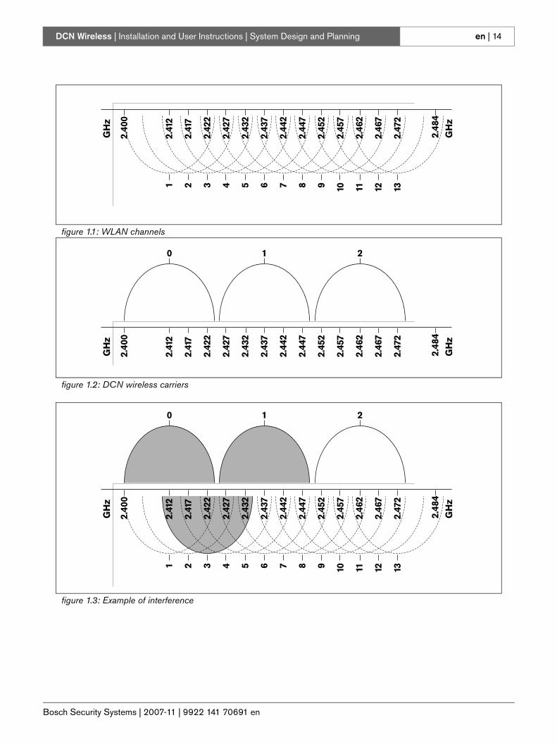
1.3.2 Wireless computer networksWireless (computer) networks can also be based on the 802.11g specification for WiFi technology. In the wireless computer networks, 13 overlapping channels are available (refer to figure 1.1).
1.3.3 CarriersIn the wireless network of DCN Wireless, three non-overlapping wireless carriers are available (refer to figure 1.2).
1.3.4 InterferenceThe wireless network of DCN Wireless can cause interference on wireless computer networks. You must make sure the DCN wireless carrier does not overlap the WLAN channel.
Refer to figure 1.3. In the example, the WLAN channel is 3. WLAN channel 3 overlaps DCN wireless carriers 0 and 1. Therefore, use DCN wireless carrier 2.
NoteAlthough the system operates on frequencies which are license free world wide, you must be aware of country specific limitations and follow them.
Bosch Security Systems | 2007-11 | 9922 141 70691 en
DCN Wireless | Installation and User Instructions | System Design and Planning en | 14
figure 1.1: WLAN channels
figure 1.2: DCN wireless carriers
1 2 3 4 5 6 7 8 9 10 11 12 13
2.41
2
GH
z
GH
z
2.41
7
2.42
2
2.42
7
2.43
2
2.43
7
2.44
2
2.44
7
2.45
2
2.45
7
2.46
2
2.46
7
2.47
2
2.48
4
2.40
0
0 1 2
2.41
2
GH
z
2.41
7
2.42
2
2.42
7
2.43
2
2.43
7
2.44
2
2.44
7
2.45
2
2.45
7
2.46
2
2.46
7
2.47
2
2.48
4
GH
z
2.40
0
figure 1.3: Example of interference
1
0 1 2
2 3 4 5 6 7 8 9 10 11 12 13
2.41
2
GH
z
2.41
7
2.42
2
2.42
7
2.43
2
2.43
7
2.44
2
2.44
7
2.45
2
2.45
7
2.46
2
2.46
7
2.47
2
2.48
4
GH
z
2.40
0
Bosch Security Systems | 2007-11 | 9922 141 70691 en
DCN Wireless | Installation and User Instructions | System Design and Planning en | 15
2 DCN design
2.1 IntroductionThe DCN Wireless has three parts: the wireless network, the DCN, and the optical network. This chapter tells how to design the DCN.
2.2 LimitsFor the DCN limits, refer to chapter 1 in the “DCN Next Generation, Installation & User Instructions”. The DCN-WCCU has the same limitations with the following deviations.
Make sure the following limits are not exceeded when you design the DCN:
Limit 1: Control capacityThe DCN-WCCU wireless central control unit can control a maximum of 95 active wired devices. The number of passive devices is without limit. The following wired active devices can be connected in any combination:• DCN-DIS Discussion Units• DCN-CON Concentus Delegate Units• DCN-DDI Dual Delegate Interface• DCN-IDESK Interpreter Desks• DCN-DDB Data Distribution Board• DCN-FVU Voting Unit
The connected wired active devices have the same limitations as the wireless devices with respect to the number of audio channels (refer to section 12.4.1).
Limit 2: Single CCU onlyThe DCN-WCCU Wireless Central Control Unit cannot be used in a multi CCU system.
Limit 3: Software PackagesOnly use the following software packages in combination with the DCN-WCCU Wireless Central Control Unit:• LBB4162/00 Standalone Automatic Camera Control
Software• LBB4187/00 Open Interface Software• DCN-SWSMV Synoptic Microphone & Voting
Control Software
Bosch Security Systems | 2007-11 | 9922 141 70691 en
DCN Wireless | Installation and User Instructions | System Design and Planning en | 16
3 Optical network design
3.1 IntroductionThe DCN Wireless has three parts: the wireless network, the DCN and the optical network. This chapter tells how to design the optical network.
3.2 Calculation toolThe calculation tool makes the planning and design of the optical network easier. You can find the calculation tool on the CD-ROM that is supplied with your system.
3.3 LimitsMake sure that these limits are not exceeded when you make the optical network:
Limit 1: Control capacityThe maximum number of nodes in the optical network is 63 (refer to section 3.4).
Limit 2: Number of devicesThe maximum number of devices that you can connect to the optical network of the central control unit is 16. The maximum number of DCN-WAP Wireless Access Points in the optical network is 1.
Limit 3: Power capacityThe maximum power that the optical network sockets of the central control unit can supply is 65 W (refer to section 3.5).
Limit 4: CablesRefer to section 3.6:• The maximum length of a POF cable is 50 m.• The maximum cable length (POF and GOF) of the
optical network is dependent on the number of nodes in the optical network.
• The minimum bend radius of a 90 degree bend in a POF cable is 110 mm.
• The minimum coiling radius of a POF cable is 110 mm.
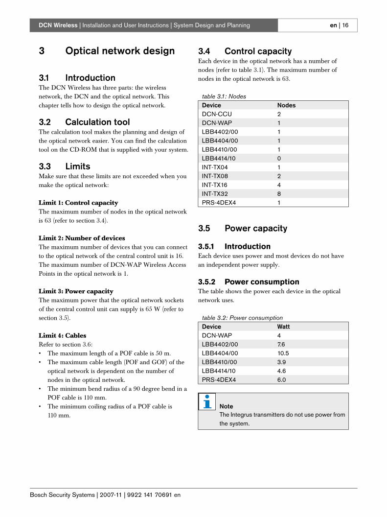
3.4 Control capacityEach device in the optical network has a number of nodes (refer to table 3.1). The maximum number of nodes in the optical network is 63.
3.5 Power capacity
3.5.1 IntroductionEach device uses power and most devices do not have an independent power supply.
3.5.2 Power consumptionThe table shows the power each device in the optical network uses.
table 3.1: NodesDevice NodesDCN-CCU 2DCN-WAP 1LBB4402/00 1LBB4404/00 1LBB4410/00 1LBB4414/10 0INT-TX04 1INT-TX08 2INT-TX16 4INT-TX32 8PRS-4DEX4 1
table 3.2: Power consumptionDevice WattDCN-WAP 4LBB4402/00 7.6LBB4404/00 10.5 LBB4410/00 3.9LBB4414/10 4.6PRS-4DEX4 6.0
NoteThe Integrus transmitters do not use power from the system.

Bosch Security Systems | 2007-11 | 9922 141 70691 en
DCN Wireless | Installation and User Instructions | System Design and Planning en | 17
3.5.3 Power supplyThe CCU supplies power for:• the optical network, and • the units connected via the DCN cables.Refer to figure 3.1.
If more power is necessary, you must install external power supplies in the optical network. The devices below can connect to external power supplies:• LBB4410/00 Network Splitter (refer to the DCN
Next Generation Installation and User Instructions).• LBB4414/10 Fiber Interface (refer to the DCN Next
Generation Installation and User Instruction).
3.5.4 Overload indicationEach optical network socket of the central control unit has a red LED that comes on to show that there is a power overload. An overload occurs when the necessary power for the devices is greater than that supplied. The sockets are deactivated and the devices connected to the central control unit do not operate. The socket checks every 8 seconds for power overloads.
3.6 Cabling
3.6.1 IntroductionMany devices in the optical network have two optical network sockets that are interchangeable. You can use the two optical network sockets to make a redundant ring.
3.6.2 DefinitionsThe optical network uses two types of cable:• POF
Plastic Optical Fiber.• GOF
Glass Optical Fiber.
figure 3.1: Optical network power supply
OK Fault
Fault
RS 232
Network
1 2
Audio In 1 Audio Out 1 Audio In 2 Audio Out 2
Mains
Port 2
115: 100-120V 50-60Hz T2.5A 250V230: 220-240V 50-60Hz T2A H 250V
RS 232 Port 1
Trunk
1 2 230
P < 65 W
DCN-WCCU
DCN-WCCU
DCN-WCCU
P < 65 W
P < 130 W
OK Fault
Fault
RS 232
Network
1 2
Audio In 1 Audio Out 1 Audio In 2 Audio Out 2
Mains
Port 2
115: 100-120V 50-60Hz T2.5A 250V230: 220-240V 50-60Hz T2A H 250V
RS 232 Port 1
Trunk
1 2 230
OK Fault
Fault
RS 232
Network
1 2
Audio In 1 Audio Out 1 Audio In 2 Audio Out 2
Mains
Port 2
115: 100-120V 50-60Hz T2.5A 250V230: 220-240V 50-60Hz T2A H 250V
RS 232 Port 1
Trunk
1 2 230
NoteIf only one of the optical network sockets has a power overload, the two overload LEDs come on.
Bosch Security Systems | 2007-11 | 9922 141 70691 en
DCN Wireless | Installation and User Instructions | System Design and Planning en | 18
3.6.3 Optical fiber lengthBecause of optical attenuation, the maximum length of optical network cables (LBB4416) is 50 m. You can use GOF and fiber interfaces to increase the distance between devices to a maximum of 1500 m.
3.6.4 Cable couplersYou can use the LBB4419/00 Cable Couplers to connect optical network cables to each other. A cable coupler causes optical attenuation. Each cable coupler decreases the maximum distance between two devices in the optical network (normally 50 meters) with 20 meters.
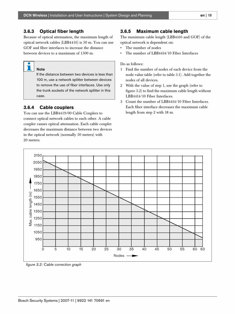
3.6.5 Maximum cable lengthThe maximum cable length (LBB4416 and GOF) of the optical network is dependent on:• The number of nodes• The number of LBB4414/10 Fiber Interfaces
Do as follows:1 Find the number of nodes of each device from the
node value table (refer to table 3.1). Add together the nodes of all devices.
2 With the value of step 1, use the graph (refer to figure 3.2) to find the maximum cable length without LBB4414/10 Fiber Interfaces.
3 Count the number of LBB4414/10 Fiber Interfaces. Each fiber interface decreases the maximum cable length from step 2 with 18 m.
NoteIf the distance between two devices is less than 100 m, use a network splitter between devices to remove the use of fiber interfaces. Use only the trunk sockets of the network splitter in this case.
figure 3.2: Cable correction graph
950
50 10 15 20 25
Nodes
30 35 40 45 50 55 60 63
1050
1150
1250
1350
1450
1550
1650
1750
1850
1950
2050
2150
Max
.cab
lele
ngth
(m)
Bosch Security Systems | 2007-11 | 9922 141 70691 en
DCN Wireless | Installation and User Instructions | System Design and Planning en | 19
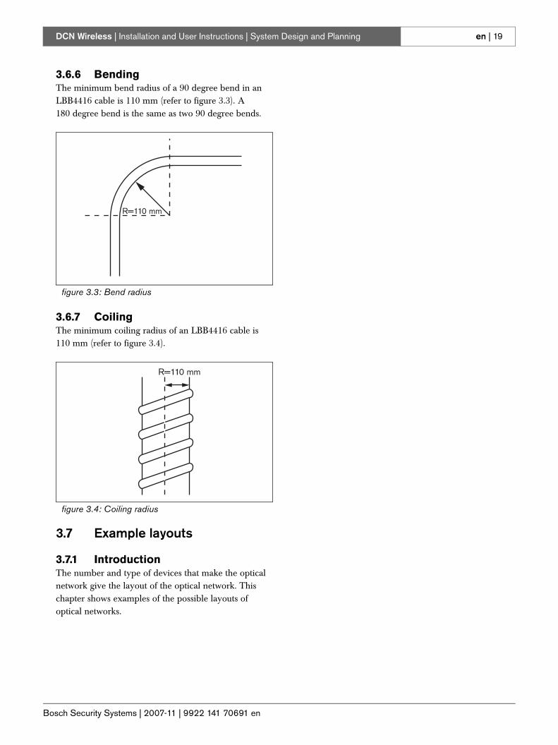
3.6.6 BendingThe minimum bend radius of a 90 degree bend in an LBB4416 cable is 110 mm (refer to figure 3.3). A 180 degree bend is the same as two 90 degree bends.
3.6.7 CoilingThe minimum coiling radius of an LBB4416 cable is 110 mm (refer to figure 3.4).
3.7 Example layouts
3.7.1 IntroductionThe number and type of devices that make the optical network give the layout of the optical network. This chapter shows examples of the possible layouts of optical networks.
figure 3.3: Bend radius
figure 3.4: Coiling radius
R=110 mm
R=110 mm
Bosch Security Systems | 2007-11 | 9922 141 70691 en
DCN Wireless | Installation and User Instructions | System Design and Planning en | 20
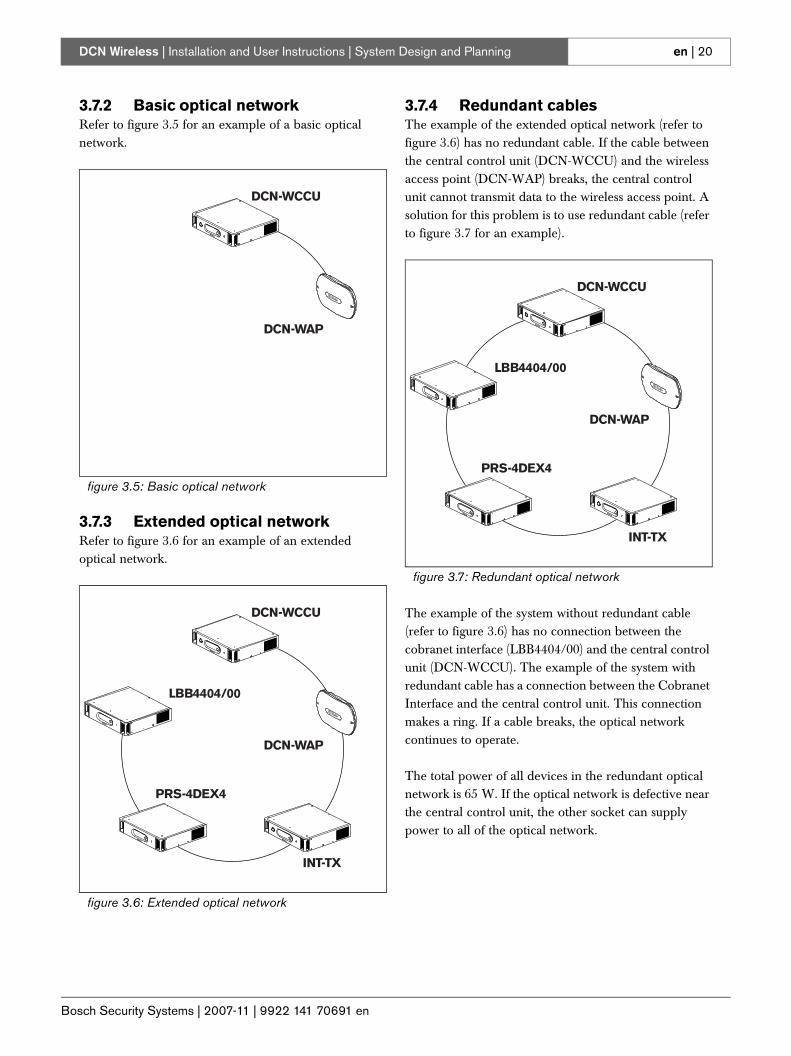
3.7.2 Basic optical networkRefer to figure 3.5 for an example of a basic optical network.
3.7.3 Extended optical networkRefer to figure 3.6 for an example of an extended optical network.
3.7.4 Redundant cablesThe example of the extended optical network (refer to figure 3.6) has no redundant cable. If the cable between the central control unit (DCN-WCCU) and the wireless access point (DCN-WAP) breaks, the central control unit cannot transmit data to the wireless access point. A solution for this problem is to use redundant cable (refer to figure 3.7 for an example).
The example of the system without redundant cable (refer to figure 3.6) has no connection between the cobranet interface (LBB4404/00) and the central control unit (DCN-WCCU). The example of the system with redundant cable has a connection between the Cobranet Interface and the central control unit. This connection makes a ring. If a cable breaks, the optical network continues to operate.
The total power of all devices in the redundant optical network is 65 W. If the optical network is defective near the central control unit, the other socket can supply power to all of the optical network.
figure 3.5: Basic optical network
figure 3.6: Extended optical network
DCN-WCCU
DCN-WAP
DCN-WCCU
DCN-WAP
LBB4404/00
INT-TX
PRS-4DEX4
figure 3.7: Redundant optical network
DCN-WCCU
DCN-WAP
LBB4404/00
INT-TX
PRS-4DEX4
Bosch Security Systems | 2007-11 | 9922 141 70691 en
DCN Wireless | Installation and User Instructions | System Design and Planning en | 21
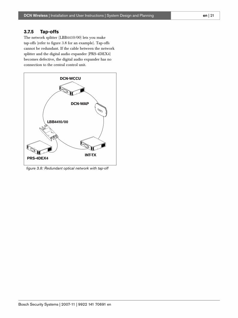
3.7.5 Tap-offsThe network splitter (LBB4410/00) lets you make tap-offs (refer to figure 3.8 for an example). Tap-offs cannot be redundant. If the cable between the network splitter and the digital audio expander (PRS-4DEX4) becomes defective, the digital audio expander has no connection to the central control unit.
figure 3.8: Redundant optical network with tap-off
DCN-WCCU
DCN-WAP
PRS-4DEX4INT-TX
LBB4410/00
Bosch Security Systems | 2007-11 | 9922 141 70691 en
DCN Wireless | Installation and User Instructions | System Design and Planning en | 22
4 Camera control
4.1 IntroductionThe central control unit can automatically point video cameras in the direction of the delegate or chairman who speaks. You can connect video cameras to the central control unit through a video switcher or directly to the central control unit. Use a video switcher to connect more that one video camera and video display to the central control unit.
4.2 ScenariosThese scenarios are possible:• Direct camera control in a system without a DCN
control PC. Refer to the DCN Next Generation Installation and User Instructions.
• Camera control through a video switcher in a system without a DCN control PC. Refer to the DCN Next Generation Installation and User Instructions.
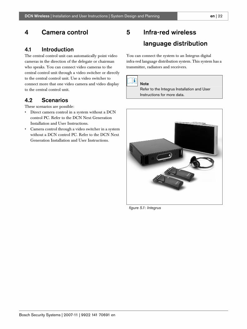
5 Infra-red wireless
language distribution
You can connect the system to an Integrus digital infra-red language distribution system. This system has a transmitter, radiators and receivers.
NoteRefer to the Integrus Installation and User Instructions for more data.
figure 5.1: Integrus
Bosch Security Systems | 2007-11 | 9922 141 70691 en
DCN Wireless | Installation and User Instructions | System Design and Planning en | 23
6 CobraNet
CobraNet is a standard for the transport of real-time digital audio and control data through an Ethernet network. A CobraNet network can transport a maximum of 64 channels of 48 kHz, 20-bit audio through a 100 Mbit link connection in each direction. Many manufacturers of professional audio devices support the CobraNet standard.
The DCN Wireless digital congress network can connect to CobraNet networks with the LBB4404/00 Cobranet Interface. For example, you can use the LBB4404/00 Cobranet Interface to:• Benefit from Ethernet infrastructure• Transport audio signals over large distances
PC data, for example data from the DCN Wireless Central Control Unit can co-exist with CobraNet data on the same Ethernet network when you use managed Ethernet switches that are approved by Peak Audio.
7 User set-up
7.1 Public areas and walkwaysKeep public areas clear of system and extension cables and connections.
7.2 Headphones/headsetsConnect headphones or headsets to:• the Wireless discussion units.• the Interpreter desks.• the Channel selector.• the Integrus receivers.
Acoustic feedback between the connected headphones or headsets and the microphone occurs when:• The volume level is set too high.• The headphones are too close to the activated
microphones (refer to section 8.7).
7.3 Speaking distanceThe recommended speaking distance from the microphone is 0.2 m to 0.4 m.
7.4 Interpreter boothsMake sure each interpreter booth has sufficient dimensions. The International Organization for Standardization (ISO) gives the specification for interpreter booths. Refer to standard ISO 2603 ‘Booths for simultaneous interpretation - General characteristics and equipment’ for more data.
NoteRefer to the DCN Next Generation Installation and User Instructions for the LBB4404/00 Cobranet Interface.
NoteRefer to the website of Peak Audio (www.peakaudio.com) for:• More data about CobraNet networks.• A list of approved Ethernet switches.
Bosch Security Systems | 2007-11 | 9922 141 70691 en
DCN Wireless | Installation and User Instructions | System Design and Planning en | 24
8 Device set-up
8.1 General
• Make sure that the area is clean.• Make sure that the air is sufficiently cool.• Make sure that there is sufficient lighting.
8.2 CablesUse different cable ducts for the extension and mains cables. Identify each cable with a label and divide trunks to manageable geographic locations. In public areas where people can touch or move above the connectors and cables, use metal protection covers. Refer to the applicable protection specification of the protection covers.
8.3 TemperatureWhen devices are in a 19-inch rack, make sure there is rack space between the devices to let sufficient air flow. Forced airflow may be necessary to keep the temperature of the devices below the maximum temperature (refer to section 9.2). This extends the lifetime of the devices.
8.4 VentilationKeep a good airflow. Airflow holes are in the front, right and left sides of all 19-inch devices (for example, the central control unit and the audio expander). • Put the devices on a hard and level surface. • Put the central control unit at minimum distance of
0.10 m from walls to let sufficient air flow.
8.5 Cleaning
1 Disconnect the mains power supply from the devices, if you want to clean the devices.
2 Use a soft cloth that is not fully moist with a weak soap and water solution.
3 Let the device fully dry before you operate the device again.
8.6 Storage
1 Disconnect the mains power supply from the devices, if you do not use the devices for a long time.
2 Keep the devices in a clean and dry area with a sufficient airflow.
3 Remove the batteries of the wireless discussion units.
CautionDo not put objects on top of devices. Objects can fall through the airflow holes. A blockage of the airflow holes can cause a risk of fire.
CautionDo not put the devices near or above a radiator, heat grill or in direct sunlight.
CautionDo not cause vibration of the devices.
CautionDo not use alcohol, ammonia or petroleum solvents or abrasive cleaners to clean the devices.
NoteIf the central control unit is stopped or disconnected from the mains power supply for more than 100 days, the values of all system parameter are erased. This includes all the values of the parameters of the interpreter desks and the wireless access point. This does not include the subscription list.
Bosch Security Systems | 2007-11 | 9922 141 70691 en
DCN Wireless | Installation and User Instructions | System Design and Planning en | 25
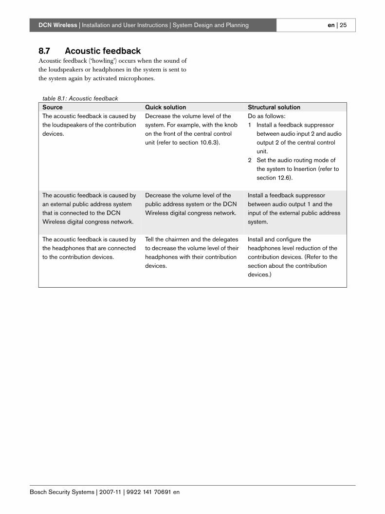
8.7 Acoustic feedbackAcoustic feedback (‘howling’) occurs when the sound of the loudspeakers or headphones in the system is sent to the system again by activated microphones.
table 8.1: Acoustic feedbackSource Quick solution Structural solutionThe acoustic feedback is caused by the loudspeakers of the contribution devices.
Decrease the volume level of the system. For example, with the knob on the front of the central control unit (refer to section 10.6.3).
Do as follows:1 Install a feedback suppressor
between audio input 2 and audio output 2 of the central control unit.
2 Set the audio routing mode of the system to Insertion (refer to section 12.6).
The acoustic feedback is caused by an external public address system that is connected to the DCN Wireless digital congress network.
Decrease the volume level of the public address system or the DCN Wireless digital congress network.
Install a feedback suppressor between audio output 1 and the input of the external public address system.
The acoustic feedback is caused by the headphones that are connected to the contribution devices.
Tell the chairmen and the delegates to decrease the volume level of their headphones with their contribution devices.
Install and configure the headphones level reduction of the contribution devices. (Refer to the section about the contribution devices.)
Bosch Security Systems | 2007-11 | 9922 141 70691 en
DCN Wireless | Installation and User Instructions | System Design and Planning en | 26
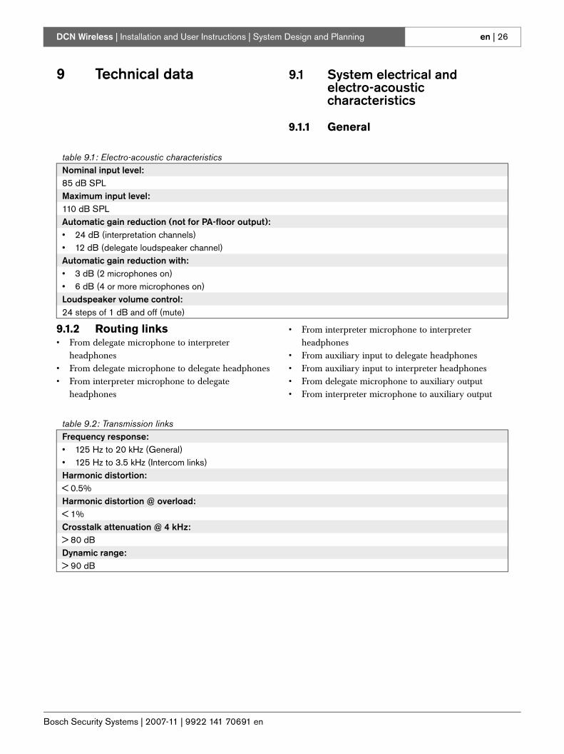
9 Technical data 9.1 System electrical and electro-acoustic characteristics
9.1.1 General
9.1.2 Routing links• From delegate microphone to interpreter
headphones• From delegate microphone to delegate headphones• From interpreter microphone to delegate
headphones
• From interpreter microphone to interpreter headphones
• From auxiliary input to delegate headphones• From auxiliary input to interpreter headphones• From delegate microphone to auxiliary output• From interpreter microphone to auxiliary output
table 9.1: Electro-acoustic characteristicsNominal input level:85 dB SPLMaximum input level:110 dB SPLAutomatic gain reduction (not for PA-floor output):• 24 dB (interpretation channels)• 12 dB (delegate loudspeaker channel)Automatic gain reduction with:• 3 dB (2 microphones on)• 6 dB (4 or more microphones on)Loudspeaker volume control:24 steps of 1 dB and off (mute)
table 9.2: Transmission linksFrequency response:• 125 Hz to 20 kHz (General)• 125 Hz to 3.5 kHz (Intercom links)Harmonic distortion:< 0.5%Harmonic distortion @ overload:< 1%Crosstalk attenuation @ 4 kHz:> 80 dBDynamic range:> 90 dB
Bosch Security Systems | 2007-11 | 9922 141 70691 en
DCN Wireless | Installation and User Instructions | System Design and Planning en | 27
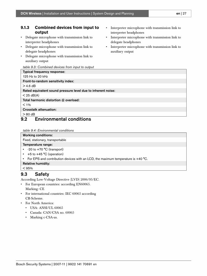
9.1.3 Combined devices from input to output
• Delegate microphone with transmission link to interpreter headphones
• Delegate microphone with transmission link to delegate headphones
• Delegate microphone with transmission link to auxiliary output
• Interpreter microphone with transmission link to interpreter headphones
• Interpreter microphone with transmission link to delegate headphones
• Interpreter microphone with transmission link to auxiliary output
9.2 Environmental conditions
9.3 SafetyAccording Low-Voltage Directive (LVD) 2006/95/EC.• For European countries: according EN60065.
Marking: CE• For international countries: IEC 60065 according
CB-Scheme.• For North America:
• USA: ANSI/UL 60065• Canada: CAN/CSA no. 60065• Marking c-CSA-us.
table 9.3: Combined devices from input to outputTypical frequency response:125 Hz to 20 kHzFront-to-random sensitivity index:> 4.6 dBRated equivalent sound pressure level due to inherent noise:< 25 dB(A)Total harmonic distortion @ overload:< 1%Crosstalk attenuation:> 80 dB
table 9.4: Environmental conditionsWorking conditions:Fixed, stationary, transportableTemperature range:• -20 to +70 °C (transport)• +5 to +45 °C (operation)• For EPS and contribution devices with an LCD, the maximum temperature is +40 °C.Relative humidity: < 95%
Bosch Security Systems | 2007-11 | 9922 141 70691 en
DCN Wireless | Installation and User Instructions | System Design and Planning en | 28
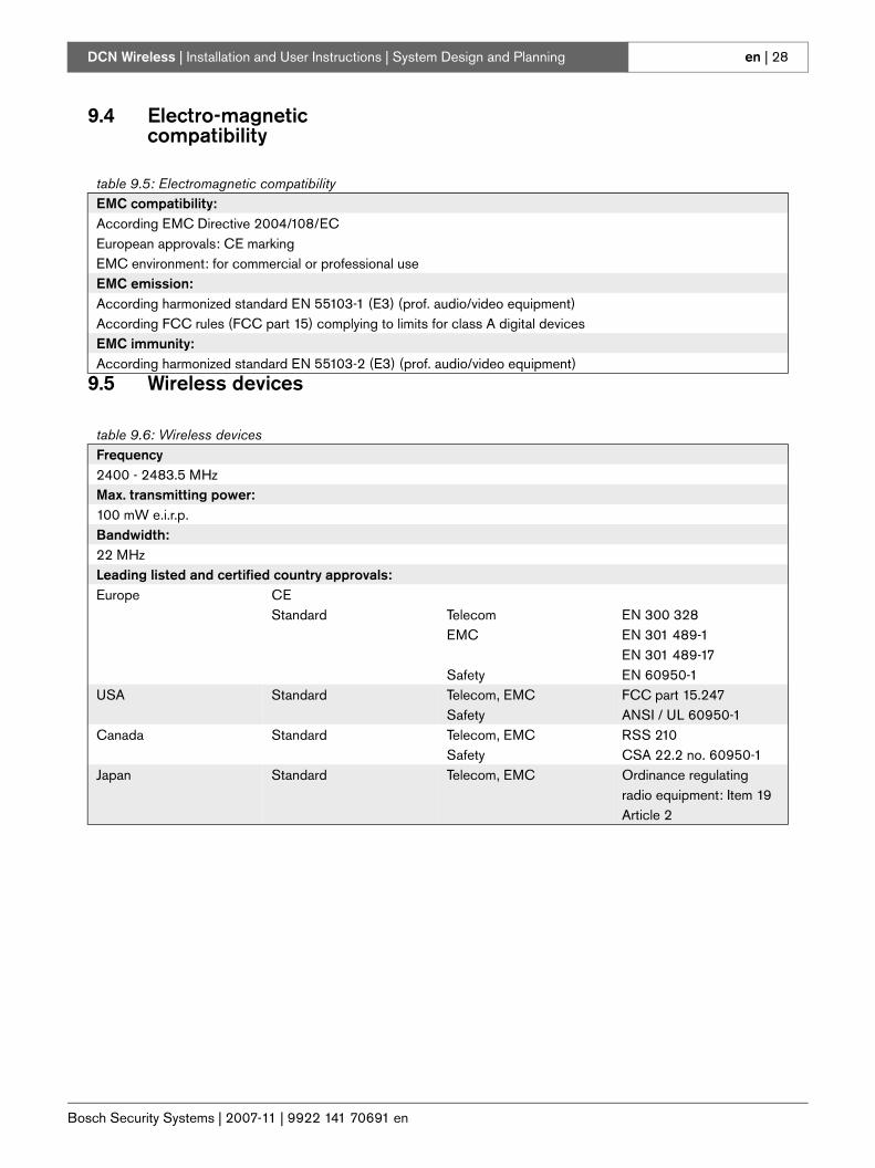
9.4 Electro-magnetic compatibility
9.5 Wireless devices
table 9.5: Electromagnetic compatibilityEMC compatibility:According EMC Directive 2004/108/ECEuropean approvals: CE markingEMC environment: for commercial or professional useEMC emission:According harmonized standard EN 55103-1 (E3) (prof. audio/video equipment)According FCC rules (FCC part 15) complying to limits for class A digital devicesEMC immunity:According harmonized standard EN 55103-2 (E3) (prof. audio/video equipment)
table 9.6: Wireless devicesFrequency2400 - 2483.5 MHzMax. transmitting power:100 mW e.i.r.p.Bandwidth:22 MHzLeading listed and certified country approvals:Europe CE
Standard TelecomEMC
Safety
EN 300 328EN 301 489-1EN 301 489-17EN 60950-1
USA Standard Telecom, EMCSafety
FCC part 15.247ANSI / UL 60950-1
Canada Standard Telecom, EMCSafety
RSS 210CSA 22.2 no. 60950-1
Japan Standard Telecom, EMC Ordinance regulating radio equipment: Item 19 Article 2
Bosch Security Systems | 2007-11 | 9922 141 70691 en
DCN Wireless | Installation and User Instructions | System Design and Planning en | 29
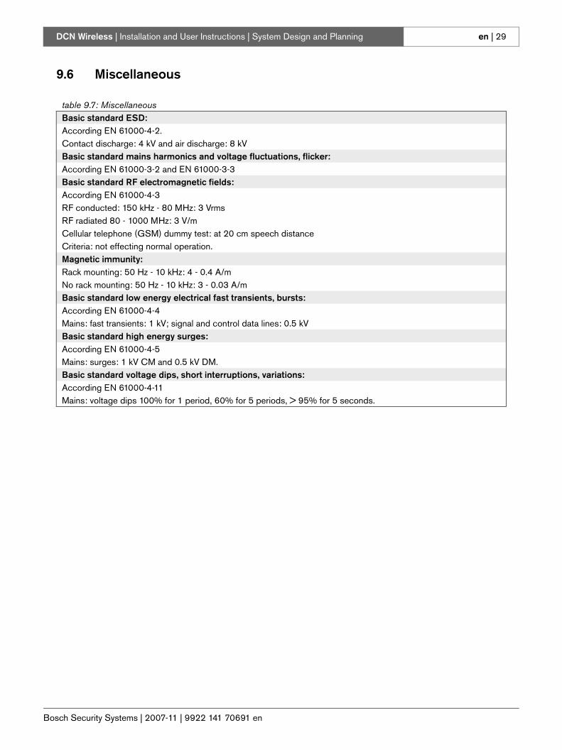
9.6 Miscellaneous
table 9.7: MiscellaneousBasic standard ESD:According EN 61000-4-2. Contact discharge: 4 kV and air discharge: 8 kVBasic standard mains harmonics and voltage fluctuations, flicker:According EN 61000-3-2 and EN 61000-3-3Basic standard RF electromagnetic fields:According EN 61000-4-3RF conducted: 150 kHz - 80 MHz: 3 VrmsRF radiated 80 - 1000 MHz: 3 V/mCellular telephone (GSM) dummy test: at 20 cm speech distanceCriteria: not effecting normal operation.Magnetic immunity:Rack mounting: 50 Hz - 10 kHz: 4 - 0.4 A/mNo rack mounting: 50 Hz - 10 kHz: 3 - 0.03 A/mBasic standard low energy electrical fast transients, bursts:According EN 61000-4-4Mains: fast transients: 1 kV; signal and control data lines: 0.5 kVBasic standard high energy surges:According EN 61000-4-5Mains: surges: 1 kV CM and 0.5 kV DM.Basic standard voltage dips, short interruptions, variations:According EN 61000-4-11Mains: voltage dips 100% for 1 period, 60% for 5 periods, > 95% for 5 seconds.
Bosch Security Systems | 2007-11 | 9922 141 70691 en
DCN Wireless | Installation and User Instructions | System Design and Planning en | 30
Intentionally left blank.
Bosch Security Systems | 2007-11 | 9922 141 70691 en
DCN Wireless | Installation and User Instructions | Central Devices en | 31
Section 2 - Central Devices
Bosch Security Systems | 2007-11 | 9922 141 70691 en
DCN Wireless | Installation and User Instructions | Central Devices en | 32
10 DCN-WCCU Wireless
Central Control Unit
10.1 IntroductionThe DCN-WCCU Wireless Central Control Unit controls the system. The central control unit can operate with or without a control PC.
10.2 Controls, connectors and indicators
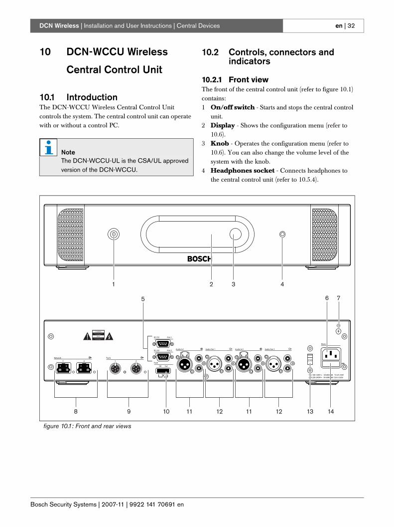
10.2.1 Front viewThe front of the central control unit (refer to figure 10.1) contains:1 On/off switch - Starts and stops the central control
unit.2 Display - Shows the configuration menu (refer to
10.6).3 Knob - Operates the configuration menu (refer to
10.6). You can also change the volume level of the system with the knob.
4 Headphones socket - Connects headphones to the central control unit (refer to 10.5.4).
NoteThe DCN-WCCU-UL is the CSA/UL approved version of the DCN-WCCU.
figure 10.1: Front and rear views
2 3 41
OK Fail
Fault
RS 232
Network
1 2
Audio In 1 Audio Out 1 Audio In 2 Audio Out 2
Mains
Port 2
115: 100-120V 50-60Hz T2.5A 250V230: 220-240V 50-60Hz T2A H 250V
RS 232 Port 1
Trunk
1 2
Avis
C autionR isk of electric shock.
Do not open.
R isk of electric shock.Do not open.
230
6 7
8 9
5
10 13 1411 12 11 12
Bosch Security Systems | 2007-11 | 9922 141 70691 en
DCN Wireless | Installation and User Instructions | Central Devices en | 33
10.2.2 Rear viewThe rear of the central control unit (refer to figure 10.1) contains:5 RS232 ports - Connects a PC, remote controllers or
video cameras to the central control unit (refer to 10.5.8).
6 Power inlet - Connects the central control unit to the mains power supply with a power cable (refer to 10.5.1).
7 Ground screw - Connects the central control unit to ground.
8 Optical network sockets - Connects the central control unit to the optical network (refer to 10.5.3).
9 DCN sockets - Connect the central control unit to the DCN (refer to 10.5.2).
10 Fault contact - Connects the central control unit to devices to sense the condition of the central control unit (refer to 10.5.7).
11 Audio inputs - Connect the central control unit to external analog audio sources (refer to 10.5.5).
12 Audio outputs - Connect the central control unit to external analog audio devices (refer to 10.5.6).
13 Voltage selector - Selects the voltage on which the central control unit must operate (refer to 10.5.1).
14 Fuse holder - Prevents damage to the internal power supply unit of the central control unit (refer to 10.5.1).
10.3 Internal settings
10.3.1 Overview
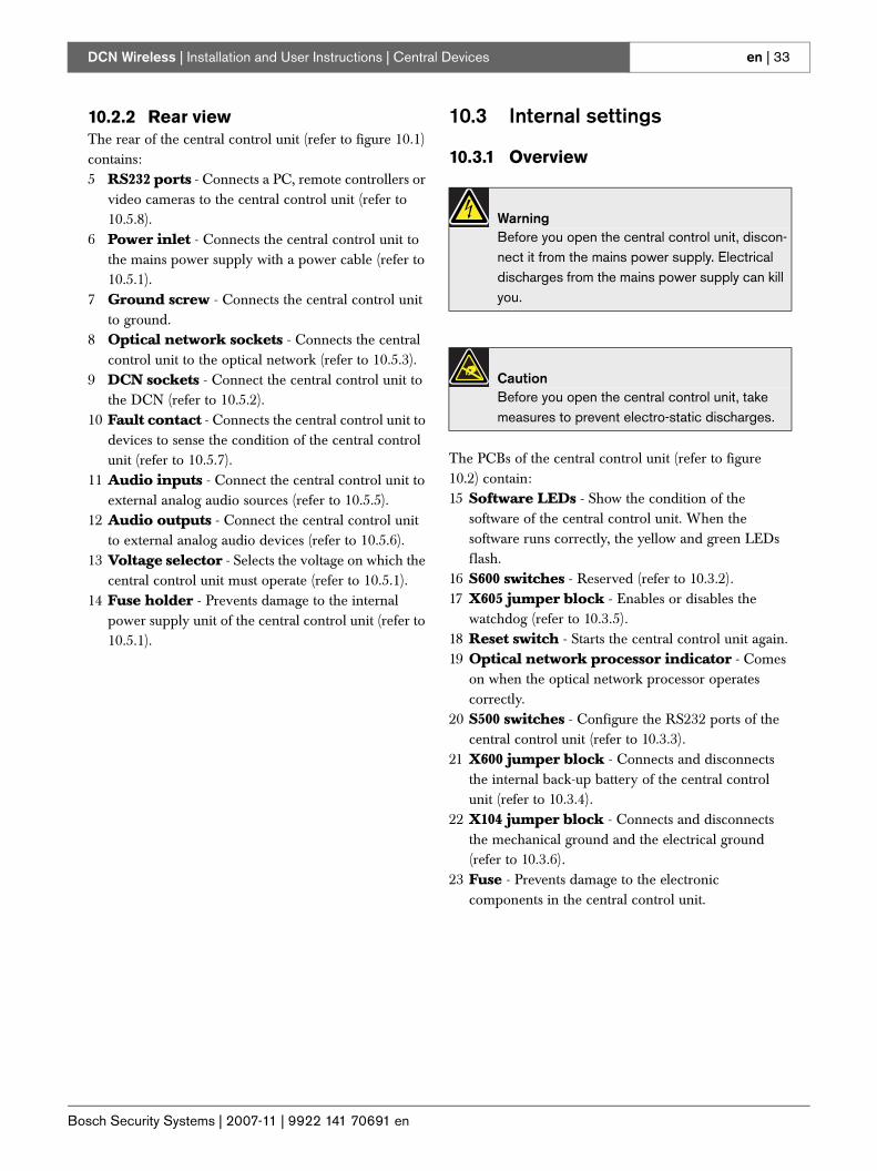
The PCBs of the central control unit (refer to figure 10.2) contain:15 Software LEDs - Show the condition of the
software of the central control unit. When the software runs correctly, the yellow and green LEDs flash.
16 S600 switches - Reserved (refer to 10.3.2).17 X605 jumper block - Enables or disables the
watchdog (refer to 10.3.5).18 Reset switch - Starts the central control unit again.19 Optical network processor indicator - Comes
on when the optical network processor operates correctly.
20 S500 switches - Configure the RS232 ports of the central control unit (refer to 10.3.3).
21 X600 jumper block - Connects and disconnects the internal back-up battery of the central control unit (refer to 10.3.4).
22 X104 jumper block - Connects and disconnects the mechanical ground and the electrical ground (refer to 10.3.6).
23 Fuse - Prevents damage to the electronic components in the central control unit.
WarningBefore you open the central control unit, discon-nect it from the mains power supply. Electrical discharges from the mains power supply can kill you.
CautionBefore you open the central control unit, take measures to prevent electro-static discharges.
Bosch Security Systems | 2007-11 | 9922 141 70691 en
DCN Wireless | Installation and User Instructions | Central Devices en | 34
figure 10.2: Internal settings
5 7
ON
31 8642
5 7
ON
31 8642
E3
E4
E1
E2
E8
E5
E9
E6
E7
E12
E10
E11
E13
E14
E15
E16
T3 R3
R2
T4
K3
T1
K4
K1R1
K2T2
R4
R7
T5
R6
R9
T6
K5
K6
R5
T7 K7
T8 K8
T9 K9
R8
K12
K13
K10
K14
K11
K15
K16
B1
B2
D3
C1
A3
C4
C2
B4 A4
D1
A2
C3
D2
D4
A1
B3
B7D7
C5 A5
D8
B5
C6 A6
D9
B8
C7 A7
C9
C8 A8
B9
D5
A9
B6D6
B13
D11
B14 A14
D12
A10C10
A11
A13
C11
A12
B10
C12
D14
B11
C13
C14
B12
D10
D13
B16C16D16
D15 A15
A16
B15C15
H1
J4 F4
H2
G3
J1 F1
G4
J2 F2
H3
G1
H4
G2
J3 F3
G8
G5J5
J9 G9
J6
H7
F6
F8H8
F7
F9H9
G6
H5
G7
F5
H6
J8
J12
G13
J10
F13
G14
F10
H13
F11
H14
H11
F12
G10
J13
H12
F14
G11
J14
J11
G12
H10
F15
F16
H15J15 G15
H16 G16J16
L1N1
L3
L2M2
L4
M1
N2
P4
N3 M3
N4 M4
P2
P3
P1
P5
M6P6
L8
M7P7
L9
N5 M5
P8 M8
N6 L6
P9 M9
N7 L7
N8
N9
L5
N12R12
M10
P14 N14
R11 M11
L10P10R10
M13
L11P11
R13
M14
L12P12
R14
N10
L13P13
M12
N11
L14
N13
N16P16R16
P15R15 N15 L15
L16
M15
T10
T11
T12
T13
T14
T16
T15
232221
1517 1618
2019
B601B602B604X14
F100
X600X103
G600
X155
S600
X605
S800
S601
B1000
X1000X1001
X104
S500
S1000
Bosch Security Systems | 2007-11 | 9922 141 70691 en
DCN Wireless | Installation and User Instructions | Central Devices en | 35
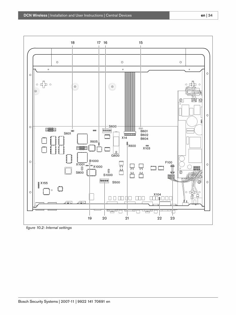
10.3.2 S600 switches
10.3.3 RS232 configurationUse the S500 switches to configure the RS232 ports of the central control unit (refer to table 10.2 and table 10.3).
table 10.1: S600 switches (* = default)Switch Position DescriptionS600-1 ON*
OFFReserved. Do not change the position of this switch.
S600-2 ONOFF*
Reserved. Do not change the position of this switch.
S600-3 ONOFF*
Reserved. Do not change the position of this switch.
S600-4 ONOFF*
Reserved. Do not change the position of this switch.
S600-5 ONOFF*
Reserved. Do not change the position of this switch.
S600-6 ONOFF*
Reserved. Do not change the position of this switch.
S600-7 ONOFF*
Reserved. Do not change the position of this switch.
S600-8 ONOFF*
Boot mode. Enables the download of new firmware (in case a download failed).Normal operation.
table 10.2: RS232 protocol (* = default)Protocol Port 1 Port 2
S500-1 S500-2 S500-5 S500-6Open interface Off Off Off OffTerminal Off On Off OnFull On* Off* On OffCamera control On On On* On*
table 10.3: RS232 baudrate (* = default)Baudrate Port 1 Port 2
S500-3 S500-4 S500-7 S500-89.6k Off Off Off Off19.2k Off On Off* On*57.6k On Off On Off115.2k On* On* On On
Bosch Security Systems | 2007-11 | 9922 141 70691 en
DCN Wireless | Installation and User Instructions | Central Devices en | 36
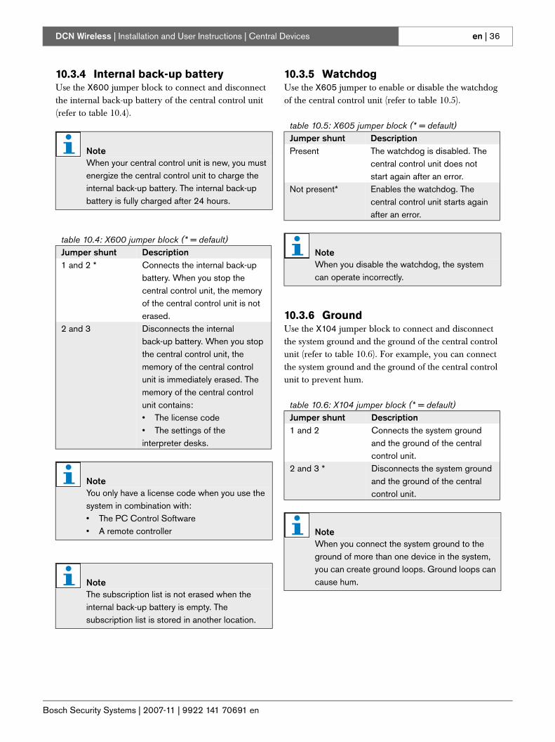
10.3.4 Internal back-up batteryUse the X600 jumper block to connect and disconnect the internal back-up battery of the central control unit (refer to table 10.4).
10.3.5 WatchdogUse the X605 jumper to enable or disable the watchdog of the central control unit (refer to table 10.5).
10.3.6 GroundUse the X104 jumper block to connect and disconnect the system ground and the ground of the central control unit (refer to table 10.6). For example, you can connect the system ground and the ground of the central control unit to prevent hum.
NoteWhen your central control unit is new, you must energize the central control unit to charge the internal back-up battery. The internal back-up battery is fully charged after 24 hours.
table 10.4: X600 jumper block (* = default)Jumper shunt Description1 and 2 * Connects the internal back-up
battery. When you stop the central control unit, the memory of the central control unit is not erased.
2 and 3 Disconnects the internal back-up battery. When you stop the central control unit, the memory of the central control unit is immediately erased. The memory of the central control unit contains:• The license code• The settings of the interpreter desks.
NoteYou only have a license code when you use the system in combination with:• The PC Control Software• A remote controller
NoteThe subscription list is not erased when the internal back-up battery is empty. The subscription list is stored in another location.
table 10.5: X605 jumper block (* = default)Jumper shunt DescriptionPresent The watchdog is disabled. The
central control unit does not start again after an error.
Not present* Enables the watchdog. The central control unit starts again after an error.
NoteWhen you disable the watchdog, the system can operate incorrectly.
table 10.6: X104 jumper block (* = default)Jumper shunt Description1 and 2 Connects the system ground
and the ground of the central control unit.
2 and 3 * Disconnects the system ground and the ground of the central control unit.
NoteWhen you connect the system ground to the ground of more than one device in the system, you can create ground loops. Ground loops can cause hum.
Bosch Security Systems | 2007-11 | 9922 141 70691 en
DCN Wireless | Installation and User Instructions | Central Devices en | 37
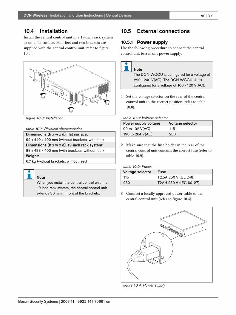
10.4 InstallationInstall the central control unit in a 19-inch rack system or on a flat surface. Four feet and two brackets are supplied with the central control unit (refer to figure 10.3).
10.5 External connections
10.5.1 Power supplyUse the following procedure to connect the central control unit to a mains power supply:
1 Set the voltage selector on the rear of the central control unit to the correct position (refer to table 10.8).
2 Make sure that the fuse holder in the rear of the central control unit contains the correct fuse (refer to table 10.9).
3 Connect a locally approved power cable to the central control unit (refer to figure 10.4).
figure 10.3: Installation
table 10.7: Physical characteristicsDimensions (h x w x d), flat surface:92 x 440 x 400 mm (without brackets, with feet)Dimensions (h x w x d), 19-inch rack system:88 x 483 x 400 mm (with brackets, without feet)Weight:6.7 kg (without brackets, without feet)
NoteWhen you install the central control unit in a 19-inch rack system, the central control unit extends 36 mm in front of the brackets.
NoteThe DCN-WCCU is configured for a voltage of 220 - 240 V(AC). The DCN-WCCU-UL is configured for a voltage of 100 - 120 V(AC).
table 10.8: Voltage selectorPower supply voltage Voltage selector90 to 132 V(AC) 115198 to 264 V(AC) 230
table 10.9: FusesVoltage selector Fuse115 T2.5A 250 V (UL 248)230 T2AH 250 V (IEC 60127)
figure 10.4: Power supply
Bosch Security Systems | 2007-11 | 9922 141 70691 en
DCN Wireless | Installation and User Instructions | Central Devices en | 38
4 Connect the power cable to a power supply.
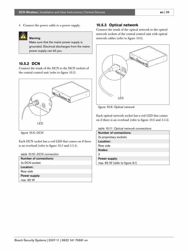
10.5.2 DCNConnect the trunk of the DCN to the DCN sockets of the central control unit (refer to figure 10.5).
Each DCN socket has a red LED that comes on if there is an overload (refer to figure 10.5 and 3.5.4).
10.5.3 Optical networkConnect the trunk of the optical network to the optical network sockets of the central control unit with optical network cables (refer to figure 10.6).
Each optical network socket has a red LED that comes on if there is an overload (refer to figure 10.6 and 3.5.4).
WarningMake sure that the mains power supply is grounded. Electrical discharges from the mains power supply can kill you.
figure 10.5: DCN
table 10.10: DCN connectionNumber of connections:2x DCN socketLocation:Rear sidePower supply:max. 65 W
LED
figure 10.6: Optical network
table 10.11: Optical network connectionsNumber of connections:2x proprietary socketsLocation:Rear sideNodes:2Power supply:max. 65 W (refer to figure 3.1)
LED

Bosch Security Systems | 2007-11 | 9922 141 70691 en
DCN Wireless | Installation and User Instructions | Central Devices en | 39
10.5.4 HeadphonesYou can connect headphones to the headphones socket of the central control unit. The headphones must have a 3.5 mm plug (refer to figure 10.7).
You can select the signal that is available on the headphones socket with the configuration menu (refer to 10.6.5).
10.5.5 Audio inputsYou can connect an external analog audio source to the audio inputs of the central control unit. The central control unit has two audio inputs. Each audio input has (refer to figure 10.8):• 1 XLR socket for balanced signals. The electric
circuits behind the XLR sockets contain transformers.
• 1 double cinch socket for unbalanced signals.
figure 10.7: 3.5 mm headphones plug, connection
table 10.12: 3.5 mm headphones plug, connectionNumber Signal1 Left2 Common3 Right
NoteYou can also connect mono headphones to the headphones socket.
2 3 1
NoteThe audio inputs change stereo signals in mono signals.
figure 10.8: Audio input, connection
table 10.13: Audio input, connectionPin Type Signal Description1 XLR Xternal Shield/ground2 Live Positive3 Return Negative4 Cinch Live Signal in5 Return Shield/ground
Audio In
2
3 4
1
5
Bosch Security Systems | 2007-11 | 9922 141 70691 en
DCN Wireless | Installation and User Instructions | Central Devices en | 40
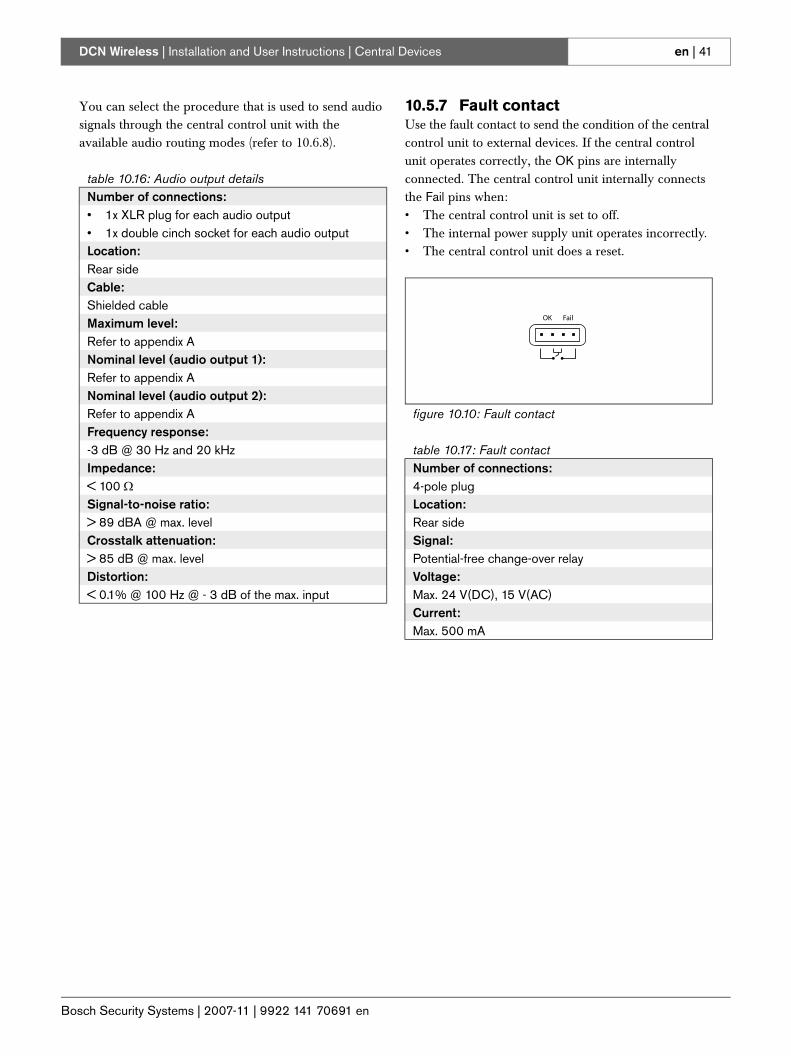
You can select the procedure that is used to send audio signals through the central control unit with the audio routing modes (refer to 10.6.8).
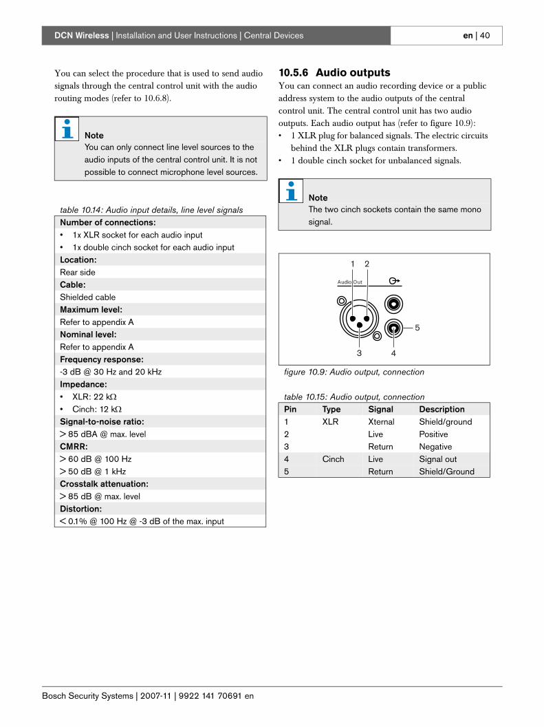
10.5.6 Audio outputsYou can connect an audio recording device or a public address system to the audio outputs of the central control unit. The central control unit has two audio outputs. Each audio output has (refer to figure 10.9): • 1 XLR plug for balanced signals. The electric circuits
behind the XLR plugs contain transformers. • 1 double cinch socket for unbalanced signals.
NoteYou can only connect line level sources to the audio inputs of the central control unit. It is not possible to connect microphone level sources.
table 10.14: Audio input details, line level signalsNumber of connections:• 1x XLR socket for each audio input• 1x double cinch socket for each audio inputLocation:Rear sideCable:Shielded cableMaximum level:Refer to appendix ANominal level:Refer to appendix AFrequency response:-3 dB @ 30 Hz and 20 kHzImpedance:• XLR: 22 kΩ• Cinch: 12 kΩSignal-to-noise ratio:> 85 dBA @ max. levelCMRR:> 60 dB @ 100 Hz> 50 dB @ 1 kHzCrosstalk attenuation:> 85 dB @ max. levelDistortion:< 0.1% @ 100 Hz @ -3 dB of the max. input
NoteThe two cinch sockets contain the same mono signal.
figure 10.9: Audio output, connection
table 10.15: Audio output, connectionPin Type Signal Description1 XLR Xternal Shield/ground2 Live Positive3 Return Negative4 Cinch Live Signal out5 Return Shield/Ground
Audio Out
1
3 4
2
5
Bosch Security Systems | 2007-11 | 9922 141 70691 en
DCN Wireless | Installation and User Instructions | Central Devices en | 41
You can select the procedure that is used to send audio signals through the central control unit with the available audio routing modes (refer to 10.6.8).
10.5.7 Fault contactUse the fault contact to send the condition of the central control unit to external devices. If the central control unit operates correctly, the OK pins are internally connected. The central control unit internally connects the Fail pins when:• The central control unit is set to off.• The internal power supply unit operates incorrectly.• The central control unit does a reset.
table 10.16: Audio output detailsNumber of connections:• 1x XLR plug for each audio output• 1x double cinch socket for each audio outputLocation:Rear sideCable:Shielded cableMaximum level:Refer to appendix ANominal level (audio output 1):Refer to appendix ANominal level (audio output 2):Refer to appendix AFrequency response:-3 dB @ 30 Hz and 20 kHz Impedance:< 100 ΩSignal-to-noise ratio:> 89 dBA @ max. levelCrosstalk attenuation:> 85 dB @ max. levelDistortion:< 0.1% @ 100 Hz @ - 3 dB of the max. input
figure 10.10: Fault contact
table 10.17: Fault contactNumber of connections:4-pole plugLocation:Rear sideSignal:Potential-free change-over relayVoltage:Max. 24 V(DC), 15 V(AC)Current:Max. 500 mA
OK Fail
Bosch Security Systems | 2007-11 | 9922 141 70691 en
DCN Wireless | Installation and User Instructions | Central Devices en | 42
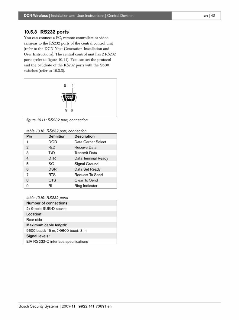
10.5.8 RS232 portsYou can connect a PC, remote controllers or video cameras to the RS232 ports of the central control unit (refer to the DCN Next Generation Installation and User Instructions). The central control unit has 2 RS232 ports (refer to figure 10.11). You can set the protocol and the baudrate of the RS232 ports with the S500 switches (refer to 10.3.3).
figure 10.11: RS232 port, connection
table 10.18: RS232 port, connectionPin Definition Description1 DCD Data Carrier Select2 RxD Receive Data3 TxD Transmit Data4 DTR Data Terminal Ready5 SG Signal Ground6 DSR Data Set Ready7 RTS Request To Send8 CTS Clear To Send9 RI Ring Indicator
table 10.19: RS232 portsNumber of connections:2x 9-pole SUB-D socketLocation:Rear sideMaximum cable length:9600 baud: 15 m, >9600 baud: 3 mSignal levels:EIA RS232-C interface specifications
9 6
15
Bosch Security Systems | 2007-11 | 9922 141 70691 en
DCN Wireless | Installation and User Instructions | Central Devices en | 43
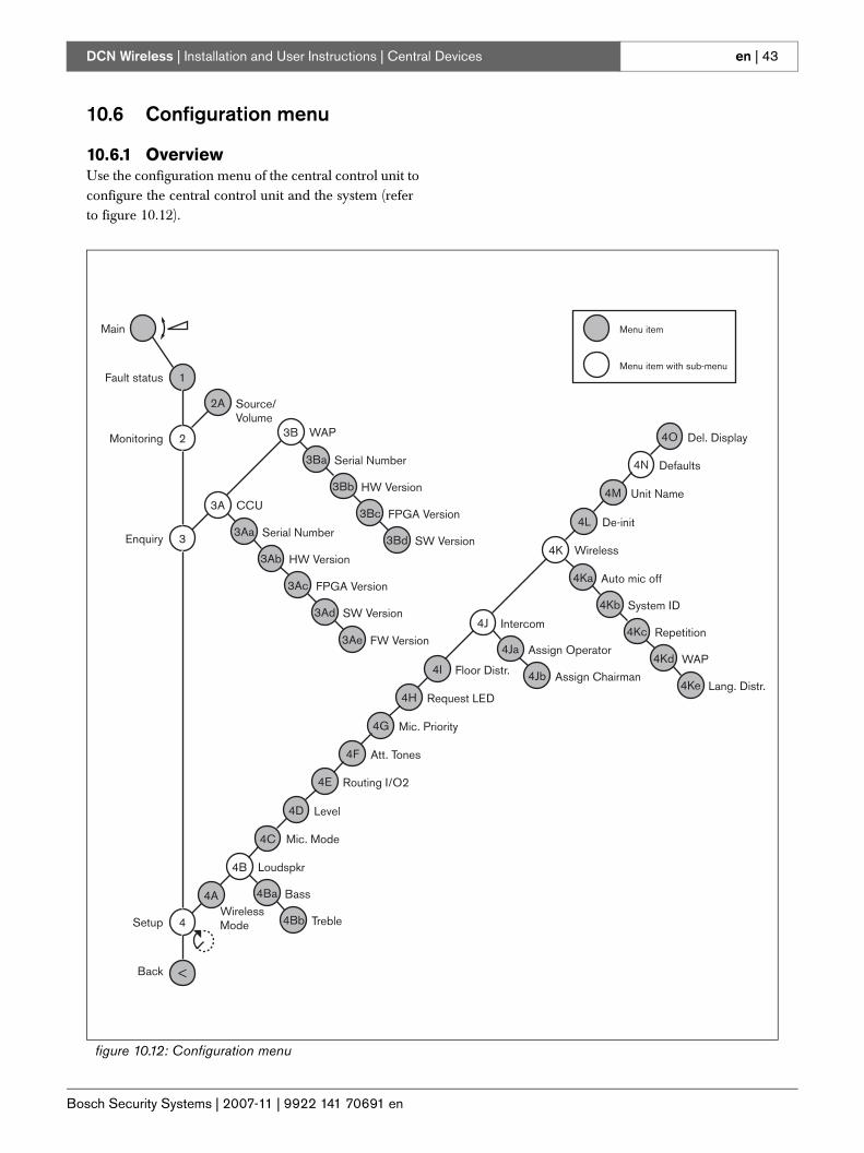
10.6 Configuration menu
10.6.1 OverviewUse the configuration menu of the central control unit to configure the central control unit and the system (refer to figure 10.12).
figure 10.12: Configuration menu
2Monitoring
2A Source/Volume
4Ba Bass
4Bb Treble
3Aa Serial Number
3Ab HW Version
3Ac FPGA Version
3Ad SW Version
3Ae FW Version
3Ba Serial Number
3Bb HW Version
3Bc FPGA Version
3Bd SW Version
4Ka Auto mic off
4Kb System ID
4Kc Repetition
4Kd WAP
4Ke Lang. Distr.
3A CCU
3B WAP
3Enquiry
1Menu item with sub-menu
Menu item
Fault status
Main
4Ja Assign Operator
4Jb Assign Chairman
4B
4A
4C
4D Level
Mic. Mode
Loudspkr
WirelessMode
4E Routing I/O2
4F Att. Tones
4G Mic. Priority
Request LED
4I
4H
Floor Distr.
4J
4K
4L De-init
Wireless
Intercom
4M Unit Name
4N Defaults
4O Del. Display
4Setup
Back <
Bosch Security Systems | 2007-11 | 9922 141 70691 en
DCN Wireless | Installation and User Instructions | Central Devices en | 44
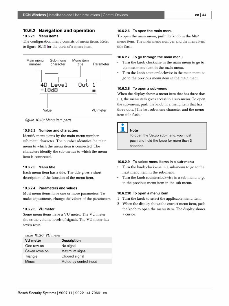
10.6.2 Navigation and operation10.6.2.1 Menu itemsThe configuration menu consists of menu items. Refer to figure 10.13 for the parts of a menu item.
10.6.2.2 Number and charactersIdentify menu items by the main menu number sub-menu character. The number identifies the main menu to which the menu item is connected. The characters identify the sub-menus to which the menu item is connected.
10.6.2.3 Menu titleEach menu item has a title. The title gives a short description of the function of the menu item.
10.6.2.4 Parameters and valuesMost menu items have one or more parameters. To make adjustments, change the values of the parameters.
10.6.2.5 VU meterSome menu items have a VU meter. The VU meter shows the volume levels of signals. The VU meter has seven rows.
10.6.2.6 To open the main menuTo open the main menu, push the knob in the Main menu item. The main menu number and the menu item title flash.
10.6.2.7 To go through the main menu• Turn the knob clockwise in the main menu to go to
the next menu item in the main menu. • Turn the knob counterclockwise in the main menu to
go to the previous menu item in the main menu.
10.6.2.8 To open a sub-menuWhen the display shows a menu item that has three dots (...), the menu item gives access to a sub-menu. To open the sub-menu, push the knob in a menu item that has three dots. (The last sub-menu character and the menu item title flash.)
10.6.2.9 To select menu items in a sub-menu• Turn the knob clockwise in a sub-menu to go to the
next menu item in the sub-menu.• Turn the knob counterclockwise in a sub-menu to go
to the previous menu item in the sub-menu.
10.6.2.10 To open a menu item1 Turn the knob to select the applicable menu item.2 When the display shows the correct menu item, push
the knob to open the menu item. The display shows a cursor.
figure 10.13: Menu item parts
table 10.20: VU meterVU meter DescriptionOne row on No signalSeven rows on Maximum signalTriangle Clipped signalMinus Muted by control input
Main menunumber
Sub-menucharacter Parameter
Value VU meter
Menu itemtitle
NoteTo open the Setup sub-menu, you must push and hold the knob for more than 3 seconds.
Bosch Security Systems | 2007-11 | 9922 141 70691 en
DCN Wireless | Installation and User Instructions | Central Devices en | 45
10.6.2.11 To select a parameter1 Open the correct menu item (refer to 10.6.2.10).2 Turn the knob to move the cursor to the parameter
that is shown.3 On the parameter, push the knob. The parameter
flashes.4 Turn the knob to go to the applicable parameter.5 When the display shows the applicable parameter,
push the knob to select the parameter. The display shows a cursor.
10.6.2.12 To change the value of a parameter1 Select the applicable parameter (refer to 10.6.2.11).2 Turn the knob to move the cursor to the value.3 Push the knob. The value flashes.4 Turn the knob to go to the value.5 When the display shows the correct value, push the
knob to select the value. The display shows a cursor.
10.6.2.13 To close a menu item1 Turn the cursor to the last character that identifies
the menu item.2 Push the knob to close the menu item. The last
character and the menu item title flash.
10.6.2.14 To close a sub-menu1 Turn the cursor to go to the second last character
that identifies the menu item.2 Push the knob to close the sub-menu. The last
character and the menu item title flash.
10.6.2.15 To close the main menu1 From the main menu, turn the primary knob
clockwise to go to the < Back menu item.2 From the < Back menu item, push the knob to go to
the Main menu item.
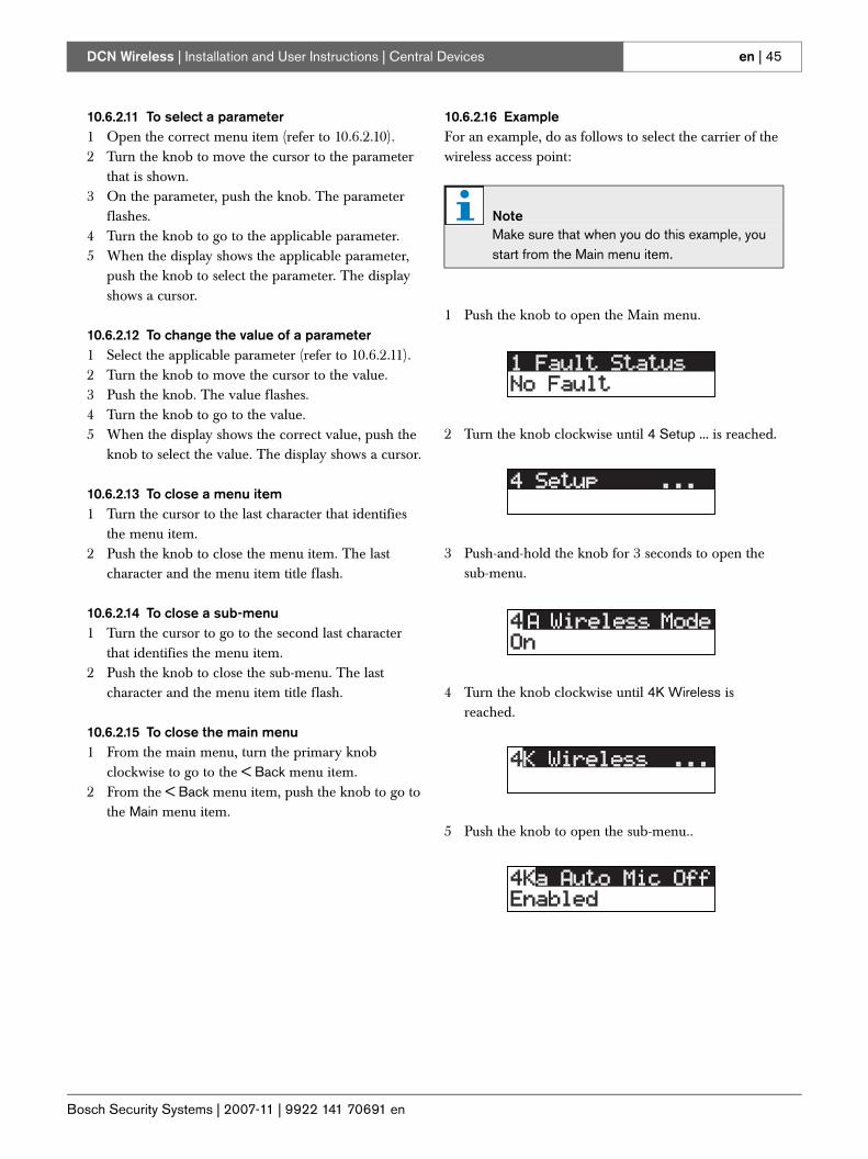
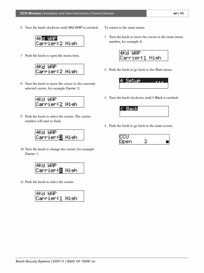
10.6.2.16 ExampleFor an example, do as follows to select the carrier of the wireless access point:
1 Push the knob to open the Main menu.
2 Turn the knob clockwise until 4 Setup ... is reached.
3 Push-and-hold the knob for 3 seconds to open the sub-menu.
4 Turn the knob clockwise until 4K Wireless is reached.
5 Push the knob to open the sub-menu..
NoteMake sure that when you do this example, you start from the Main menu item.
Bosch Security Systems | 2007-11 | 9922 141 70691 en
DCN Wireless | Installation and User Instructions | Central Devices en | 46
6 Turn the knob clockwise until 4Kd WAP is reached.
7 Push the knob to open the menu item.
8 Turn the knob to move the cursor to the currently selected carrier, for example Carrier: 2.
9 Push the knob to select the carrier. The carrier number will start to flash.
10 Turn the knob to change the carrier, for example Carrier: 1.
11 Push the knob to select the carrier.
To return to the main menu:
1 Turn the knob to move the cursor to the main menu number, for example 4.
2 Push the knob to go back to the Main menu.
3 Turn the knob clockwise until < Back is reached.
4 Push the knob to go back to the main screen.
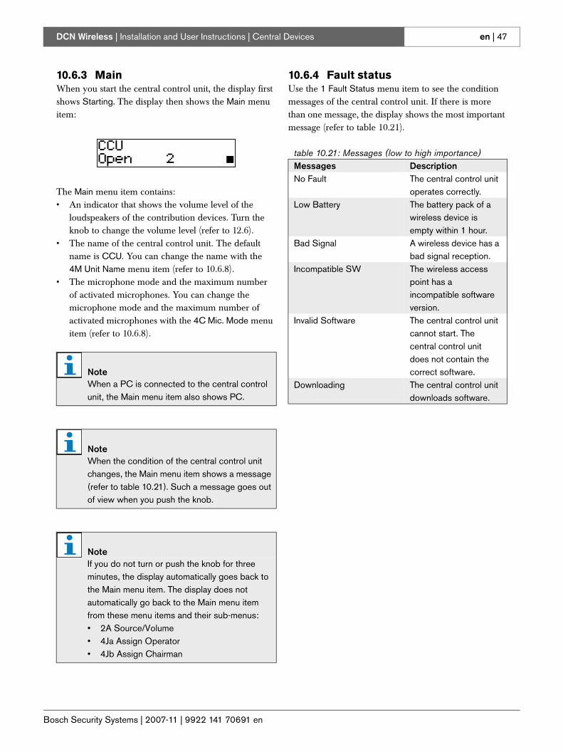
Bosch Security Systems | 2007-11 | 9922 141 70691 en
DCN Wireless | Installation and User Instructions | Central Devices en | 47
10.6.3 MainWhen you start the central control unit, the display first shows Starting. The display then shows the Main menu item:
The Main menu item contains:• An indicator that shows the volume level of the
loudspeakers of the contribution devices. Turn the knob to change the volume level (refer to 12.6).
• The name of the central control unit. The default name is CCU. You can change the name with the 4M Unit Name menu item (refer to 10.6.8).
• The microphone mode and the maximum number of activated microphones. You can change the microphone mode and the maximum number of activated microphones with the 4C Mic. Mode menu item (refer to 10.6.8).
10.6.4 Fault statusUse the 1 Fault Status menu item to see the condition messages of the central control unit. If there is more than one message, the display shows the most important message (refer to table 10.21).
NoteWhen a PC is connected to the central control unit, the Main menu item also shows PC.
NoteWhen the condition of the central control unit changes, the Main menu item shows a message (refer to table 10.21). Such a message goes out of view when you push the knob.
NoteIf you do not turn or push the knob for three minutes, the display automatically goes back to the Main menu item. The display does not automatically go back to the Main menu item from these menu items and their sub-menus:• 2A Source/Volume• 4Ja Assign Operator• 4Jb Assign Chairman
table 10.21: Messages (low to high importance)Messages DescriptionNo Fault The central control unit
operates correctly.Low Battery The battery pack of a
wireless device is empty within 1 hour.
Bad Signal A wireless device has a bad signal reception.
Incompatible SW The wireless access point has a incompatible software version.
Invalid Software The central control unit cannot start. The central control unit does not contain the correct software.
Downloading The central control unit downloads software.
Bosch Security Systems | 2007-11 | 9922 141 70691 en
DCN Wireless | Installation and User Instructions | Central Devices en | 48
10.6.5 MonitoringUse the 2 Monitoring menu item to open the Monitoring sub-menu (refer to table 10.22).
10.6.6 DCN-WCCU EnquiryUse the 3A CCU menu item to open the CCU sub-menu. The menu items in this sub-menu give general data about the central control unit (refer to table 10.23).
table 10.22: Monitoring sub-menu (* = default)Menu item Parameter Value Description2A Source/Volume Signal:
FloorInput 1Input 2Output 1Output 2
Volume level:-31 to 0 dB (16 dB*)-31 to 0 dB (16 dB*)-31 to 0 dB (16 dB*)-31 to 0 dB (16 dB*)-31 to 0 dB (16 dB*)
The signal that is available on the headphones socket of the central control unit and its volume level.
NoteThis data must be mentioned in all service requests and failure reports.
table 10.23: DCN-WCCU Enquiry sub-menu (* = default)Menu item Parameter Value (read-only) Description3Aa Serial Nr --- e.g. 20.0.00362 The hexadecimal serial
number of the central control unit.
3Ab HW Version --- e.g. 3.0 The version number of the hardware of the central control unit.
3Ac FPGA Version --- e.g. 1.06 The version number of the FPGA firmware of the central control unit.
3Ad SW Version --- MM.mm.bbbbe.g. 2.20.1234
The version number of the software of the central control unit.• MM: Major release no.• mm: Minor release no.• bbbb: build no.
3Ae FW Version --- MM.mm.bbbbe.g. 4.00.1234
The version number of the firmware of the central control unit.• MM: Major release no.• mm: Minor release no.• bbbb: build no.
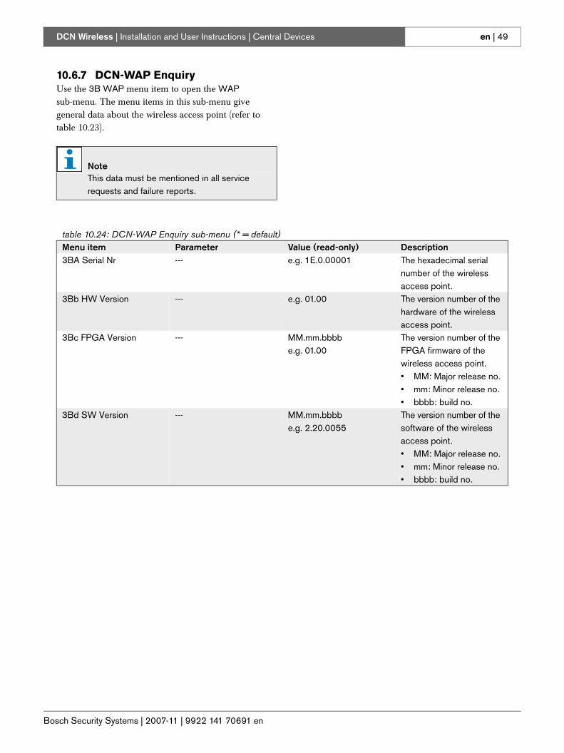
Bosch Security Systems | 2007-11 | 9922 141 70691 en
DCN Wireless | Installation and User Instructions | Central Devices en | 49
10.6.7 DCN-WAP EnquiryUse the 3B WAP menu item to open the WAP sub-menu. The menu items in this sub-menu give general data about the wireless access point (refer to table 10.23).
NoteThis data must be mentioned in all service requests and failure reports.
table 10.24: DCN-WAP Enquiry sub-menu (* = default)Menu item Parameter Value (read-only) Description3BA Serial Nr --- e.g. 1E.0.00001 The hexadecimal serial
number of the wireless access point.
3Bb HW Version --- e.g. 01.00 The version number of the hardware of the wireless access point.
3Bc FPGA Version --- MM.mm.bbbbe.g. 01.00
The version number of the FPGA firmware of the wireless access point.• MM: Major release no.• mm: Minor release no.• bbbb: build no.
3Bd SW Version --- MM.mm.bbbbe.g. 2.20.0055
The version number of the software of the wireless access point.• MM: Major release no.• mm: Minor release no.• bbbb: build no.
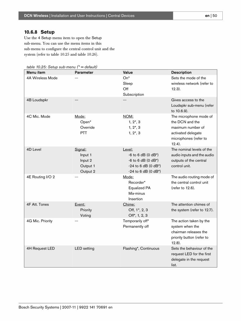
Bosch Security Systems | 2007-11 | 9922 141 70691 en
DCN Wireless | Installation and User Instructions | Central Devices en | 50
10.6.8 SetupUse the 4 Setup menu item to open the Setup sub-menu. You can use the menu items in this sub-menu to configure the central control unit and the system (refer to table 10.25 and table 10.26).
table 10.25: Setup sub-menu (* = default)Menu item Parameter Value Description4A Wireless Mode --- On*
SleepOff Subscription
Sets the mode of the wireless network (refer to 12.3).
4B Loudspkr --- --- Gives access to the Loudspkr sub-menu (refer to 10.6.9).
4C Mic. Mode Mode:Open*OverridePTT
NOM:1, 2*, 31, 2*, 31, 2*, 3
The microphone mode of the DCN and the maximum number of activated delegate microphones (refer to 12.4).
4D Level Signal:Input 1Input 2Output 1Output 2
Level:-6 to 6 dB (0 dB*)-6 to 6 dB (0 dB*)-24 to 6 dB (0 dB*)-24 to 6 dB (0 dB*)
The nominal levels of the audio inputs and the audio outputs of the central control unit.
4E Routing I/O 2 --- Mode:Recorder*Equalized PAMix-minusInsertion
The audio routing mode of the central control unit (refer to 12.6).
4F Att. Tones Event:PriorityVoting
Chime:Off, 1*, 2, 3Off*, 1, 2, 3
The attention chimes of the system (refer to 12.7).
4G Mic. Priority --- Temporarily off*Permanently off
The action taken by the system when the chairman releases the priority button (refer to 12.8).
4H Request LED LED setting Flashing*, Continuous Sets the behaviour of the request LED for the first delegate in the request list.
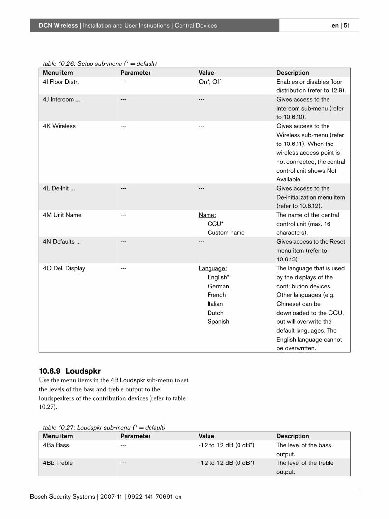
Bosch Security Systems | 2007-11 | 9922 141 70691 en
DCN Wireless | Installation and User Instructions | Central Devices en | 51
10.6.9 LoudspkrUse the menu items in the 4B Loudspkr sub-menu to set the levels of the bass and treble output to the loudspeakers of the contribution devices (refer to table 10.27).
table 10.26: Setup sub-menu (* = default)Menu item Parameter Value Description4I Floor Distr. --- On*, Off Enables or disables floor
distribution (refer to 12.9).4J Intercom ... --- --- Gives access to the
Intercom sub-menu (refer to 10.6.10).
4K Wireless --- --- Gives access to the Wireless sub-menu (refer to 10.6.11). When the wireless access point is not connected, the central control unit shows Not Available.
4L De-Init ... --- --- Gives access to the De-initialization menu item (refer to 10.6.12).
4M Unit Name --- Name:CCU*Custom name
The name of the central control unit (max. 16 characters).
4N Defaults ... --- --- Gives access to the Reset menu item (refer to 10.6.13)
4O Del. Display --- Language:English*GermanFrenchItalianDutchSpanish
The language that is used by the displays of the contribution devices. Other languages (e.g. Chinese) can be downloaded to the CCU, but will overwrite the default languages. The English language cannot be overwritten.
table 10.27: Loudspkr sub-menu (* = default)Menu item Parameter Value Description4Ba Bass --- -12 to 12 dB (0 dB*) The level of the bass
output.4Bb Treble --- -12 to 12 dB (0 dB*) The level of the treble
output.
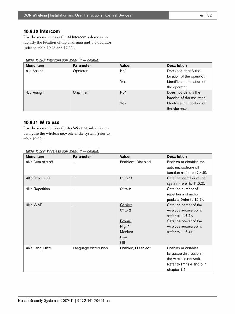
Bosch Security Systems | 2007-11 | 9922 141 70691 en
DCN Wireless | Installation and User Instructions | Central Devices en | 52
10.6.10 IntercomUse the menu items in the 4J Intercom sub-menu to identify the location of the chairman and the operator (refer to table 10.28 and 12.10).
10.6.11 WirelessUse the menu items in the 4K Wireless sub-menu to configure the wireless network of the system (refer to table 10.29).
table 10.28: Intercom sub-menu (* = default)Menu item Parameter Value Description4Ja Assign Operator No*
Yes
Does not identify the location of the operator.Identifies the location of the operator.
4Jb Assign Chairman No*
Yes
Does not identify the location of the chairman.Identifies the location of the chairman.
table 10.29: Wireless sub-menu (* = default)Menu item Parameter Value Description4Ka Auto mic off --- Enabled*, Disabled Enables or disables the
auto microphone off function (refer to 12.4.5).
4Kb System ID --- 0* to 15 Sets the identifier of the system (refer to 11.6.2).
4Kc Repetition --- 0* to 2 Sets the number of repetitions of audio packets (refer to 12.5).
4Kd WAP --- Carrier:0* to 2
Power:High*MediumLow Off
Sets the carrier of the wireless access point (refer to 11.6.3).Sets the power of the wireless access point (refer to 11.6.4).
4Ke Lang. Distr. Language distribution Enabled, Disabled* Enables or disables language distribution in the wireless network. Refer to limits 4 and 5 in chapter 1.2
Bosch Security Systems | 2007-11 | 9922 141 70691 en
DCN Wireless | Installation and User Instructions | Central Devices en | 53
10.6.12 De-initUse the 4L De-initialize menu item in the 4L De-Init sub-menu to erase the addresses of the contribution devices and the interpretation devices (refer to table 10.30 and 12.2).
10.6.13 DefaultsUse the 4N Defaults sub-menu to set all parameters to the default values in the configuration menu (refer to table 10.31). This includes the values of the parameters of the interpreter desks. These parameters are not changed:• The subscription list of wireless devices• The name of the central control unit
10.6.14 Delegate DisplayUse the 4O menu to select a language that is used on the display of a wired contribution device (refer to table 10.32).
table 10.30: De-init sub-menu (* = default)Menu item Parameter Value Description4L De-init De-initialize None*
Wired
Wireless
Does not erase the addresses.Erases the addresses of the wired devices in the DCN.Erases the subscription list of the devices in the wireless network.
table 10.31: Defaults sub-menu (* = default)Menu item Parameter Value Description4N Defaults Reset to defaults? No*
Yes
Does not put back the default values.Sets all parameters to the default values.
table 10.32: Delegate display sub-menu
4O Del. Display --- Language:English*GermanFrenchItalianDutchSpanish
The language that is used by the displays of the contribution devices. Other languages (e.g. Chinese) can be downloaded to the CCU, but will overwrite the default languages. The English language cannot be overwritten.
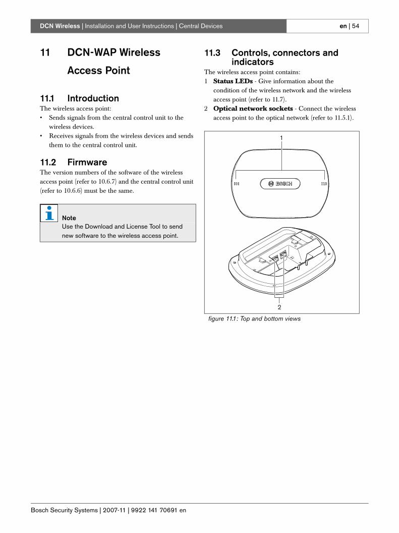
Bosch Security Systems | 2007-11 | 9922 141 70691 en
DCN Wireless | Installation and User Instructions | Central Devices en | 54
11 DCN-WAP Wireless
Access Point
11.1 IntroductionThe wireless access point:• Sends signals from the central control unit to the
wireless devices.• Receives signals from the wireless devices and sends
them to the central control unit.
11.2 FirmwareThe version numbers of the software of the wireless access point (refer to 10.6.7) and the central control unit (refer to 10.6.6) must be the same.
11.3 Controls, connectors and indicators
The wireless access point contains:1 Status LEDs - Give information about the
condition of the wireless network and the wireless access point (refer to 11.7).
2 Optical network sockets - Connect the wireless access point to the optical network (refer to 11.5.1).
NoteUse the Download and License Tool to send new software to the wireless access point.
figure 11.1: Top and bottom views
1
2
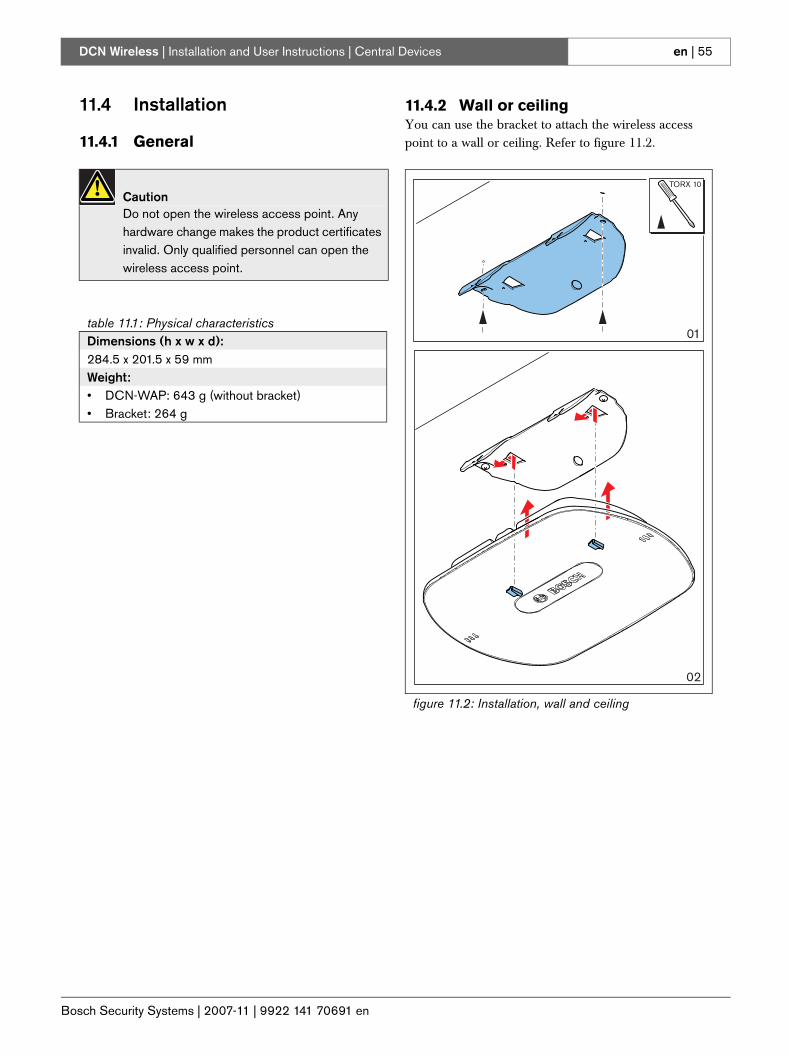
Bosch Security Systems | 2007-11 | 9922 141 70691 en
DCN Wireless | Installation and User Instructions | Central Devices en | 55
11.4 Installation
11.4.1 General
11.4.2 Wall or ceilingYou can use the bracket to attach the wireless access point to a wall or ceiling. Refer to figure 11.2.
CautionDo not open the wireless access point. Any hardware change makes the product certificates invalid. Only qualified personnel can open the wireless access point.
table 11.1: Physical characteristicsDimensions (h x w x d):284.5 x 201.5 x 59 mmWeight:• DCN-WAP: 643 g (without bracket)• Bracket: 264 g
figure 11.2: Installation, wall and ceiling
02
01
TORX 10
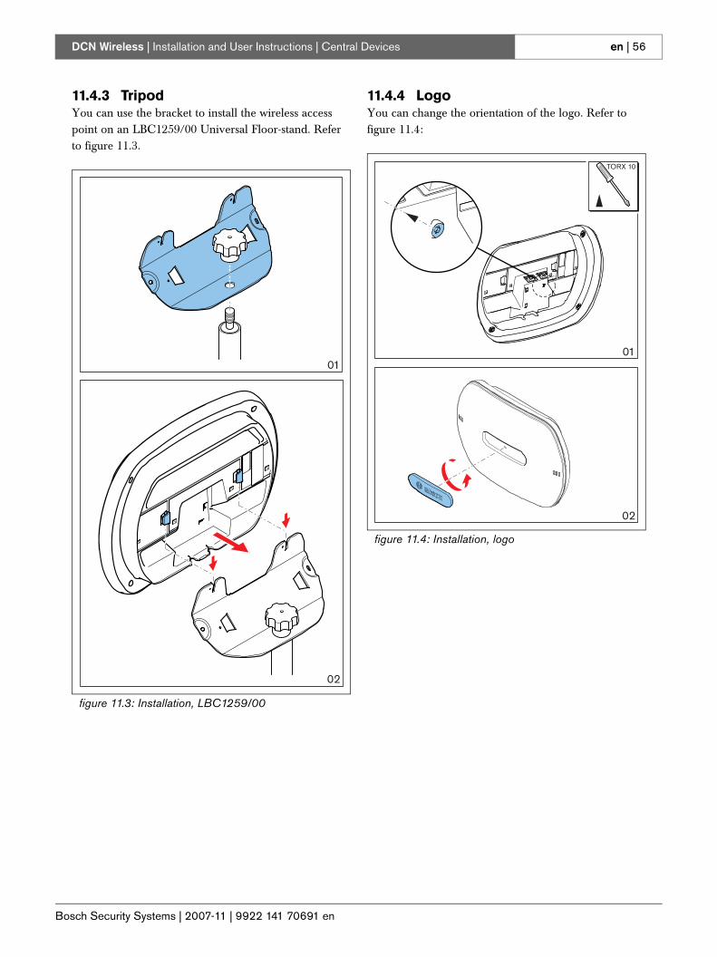
Bosch Security Systems | 2007-11 | 9922 141 70691 en
DCN Wireless | Installation and User Instructions | Central Devices en | 56
11.4.3 TripodYou can use the bracket to install the wireless access point on an LBC1259/00 Universal Floor-stand. Refer to figure 11.3.
11.4.4 LogoYou can change the orientation of the logo. Refer to figure 11.4:
figure 11.3: Installation, LBC1259/00
02
01
figure 11.4: Installation, logo
02
01
TORX 10
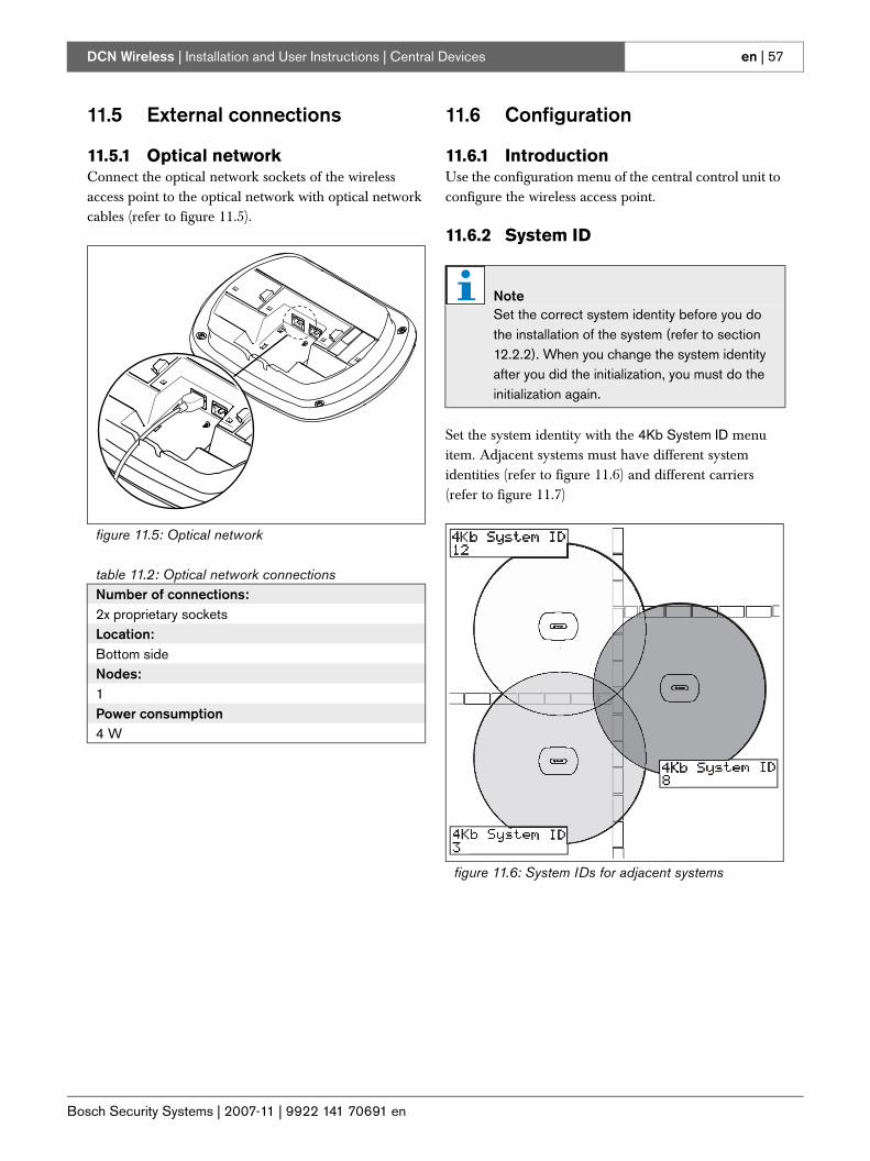
Bosch Security Systems | 2007-11 | 9922 141 70691 en
DCN Wireless | Installation and User Instructions | Central Devices en | 57
11.5 External connections
11.5.1 Optical networkConnect the optical network sockets of the wireless access point to the optical network with optical network cables (refer to figure 11.5).
11.6 Configuration
11.6.1 IntroductionUse the configuration menu of the central control unit to configure the wireless access point.
11.6.2 System ID
Set the system identity with the 4Kb System ID menu item. Adjacent systems must have different system identities (refer to figure 11.6) and different carriers (refer to figure 11.7)
figure 11.5: Optical network
table 11.2: Optical network connectionsNumber of connections:2x proprietary socketsLocation:Bottom sideNodes:1Power consumption4 W
NoteSet the correct system identity before you do the installation of the system (refer to section 12.2.2). When you change the system identity after you did the initialization, you must do the initialization again.
figure 11.6: System IDs for adjacent systems
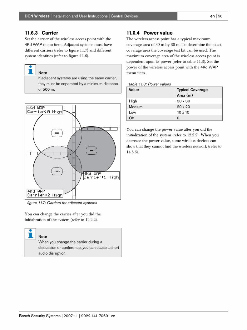
Bosch Security Systems | 2007-11 | 9922 141 70691 en
DCN Wireless | Installation and User Instructions | Central Devices en | 58
11.6.3 CarrierSet the carrier of the wireless access point with the 4Kd WAP menu item. Adjacent systems must have different carriers (refer to figure 11.7) and different system identities (refer to figure 11.6).
You can change the carrier after you did the initialization of the system (refer to 12.2.2).
11.6.4 Power valueThe wireless access point has a typical maximum coverage area of 30 m by 30 m. To determine the exact coverage area the coverage test kit can be used. The maximum coverage area of the wireless access point is dependent upon its power (refer to table 11.3). Set the power of the wireless access point with the 4Kd WAP menu item.
You can change the power value after you did the initialization of the system (refer to 12.2.2). When you decrease the power value, some wireless devices can show that they cannot find the wireless network (refer to 14.8.6).
NoteIf adjacent systems are using the same carrier, they must be separated by a minimum distance of 500 m.
figure 11.7: Carriers for adjacent systems
NoteWhen you change the carrier during a discussion or conference, you can cause a short audio disruption.
table 11.3: Power valuesValue Typical Coverage
Area (m)High 30 x 30Medium 20 x 20Low 10 x 10Off 0
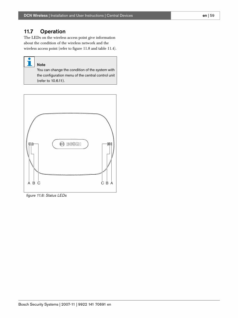
Bosch Security Systems | 2007-11 | 9922 141 70691 en
DCN Wireless | Installation and User Instructions | Central Devices en | 59
11.7 OperationThe LEDs on the wireless access point give information about the condition of the wireless network and the wireless access point (refer to figure 11.8 and table 11.4).
NoteYou can change the condition of the system with the configuration menu of the central control unit (refer to 10.6.11).
figure 11.8: Status LEDs
A B C C B A
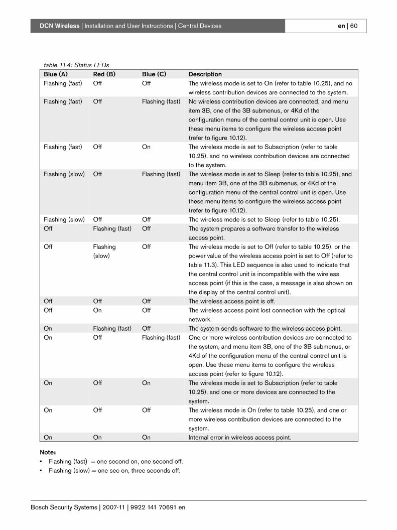
Bosch Security Systems | 2007-11 | 9922 141 70691 en
DCN Wireless | Installation and User Instructions | Central Devices en | 60
Note:• Flashing (fast) = one second on, one second off.• Flashing (slow) = one sec on, three seconds off.
table 11.4: Status LEDsBlue (A) Red (B) Blue (C) DescriptionFlashing (fast) Off Off The wireless mode is set to On (refer to table 10.25), and no
wireless contribution devices are connected to the system.Flashing (fast) Off Flashing (fast) No wireless contribution devices are connected, and menu
item 3B, one of the 3B submenus, or 4Kd of the configuration menu of the central control unit is open. Use these menu items to configure the wireless access point (refer to figure 10.12).
Flashing (fast) Off On The wireless mode is set to Subscription (refer to table 10.25), and no wireless contribution devices are connected to the system.
Flashing (slow) Off Flashing (fast) The wireless mode is set to Sleep (refer to table 10.25), and menu item 3B, one of the 3B submenus, or 4Kd of the configuration menu of the central control unit is open. Use these menu items to configure the wireless access point (refer to figure 10.12).
Flashing (slow) Off Off The wireless mode is set to Sleep (refer to table 10.25).Off Flashing (fast) Off The system prepares a software transfer to the wireless
access point.Off Flashing
(slow)Off The wireless mode is set to Off (refer to table 10.25), or the
power value of the wireless access point is set to Off (refer to table 11.3). This LED sequence is also used to indicate that the central control unit is incompatible with the wireless access point (if this is the case, a message is also shown on the display of the central control unit).
Off Off Off The wireless access point is off.Off On Off The wireless access point lost connection with the optical
network.On Flashing (fast) Off The system sends software to the wireless access point.On Off Flashing (fast) One or more wireless contribution devices are connected to
the system, and menu item 3B, one of the 3B submenus, or 4Kd of the configuration menu of the central control unit is open. Use these menu items to configure the wireless access point (refer to figure 10.12).
On Off On The wireless mode is set to Subscription (refer to table 10.25), and one or more devices are connected to the system.
On Off Off The wireless mode is On (refer to table 10.25), and one or more wireless contribution devices are connected to the system.
On On On Internal error in wireless access point.
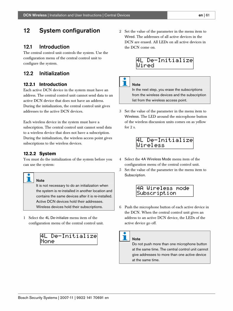
Bosch Security Systems | 2007-11 | 9922 141 70691 en
DCN Wireless | Installation and User Instructions | Central Devices en | 61
12 System configuration
12.1 IntroductionThe central control unit controls the system. Use the configuration menu of the central control unit to configure the system.
12.2 Initialization
12.2.1 IntroductionEach active DCN device in the system must have an address. The central control unit cannot send data to an active DCN device that does not have an address. During the initialization, the central control unit gives addresses to the active DCN devices.
Each wireless device in the system must have a subscription. The central control unit cannot send data to a wireless device that does not have a subscription. During the initialization, the wireless access point gives subscriptions to the wireless devices.
12.2.2 SystemYou must do the initialization of the system before you can use the system:
1 Select the 4L De-initialize menu item of the configuration menu of the central control unit.
2 Set the value of the parameter in the menu item to Wired. The addresses of all active devices in the DCN are erased. All LEDs on all active devices in the DCN come on.
3 Set the value of the parameter in the menu item to Wireless. The LED around the microphone button of the wireless discussion units comes on as yellow for 2 s.
4 Select the 4A Wireless Mode menu item of the configuration menu of the central control unit.
5 Set the value of the parameter in the menu item to Subscription.
6 Push the microphone button of each active device in the DCN. When the central control unit gives an address to an active DCN device, the LEDs of the active device go off.
NoteIt is not necessary to do an initialization when the system is re-installed in another location and contains the same devices after it is re-installed. Active DCN devices hold their addresses. Wireless devices hold their subscriptions.
NoteIn the next step, you erase the subscriptions from the wireless devices and the subscription list from the wireless access point.
NoteDo not push more than one microphone button at the same time. The central control unit cannot give addresses to more than one active device at the same time.
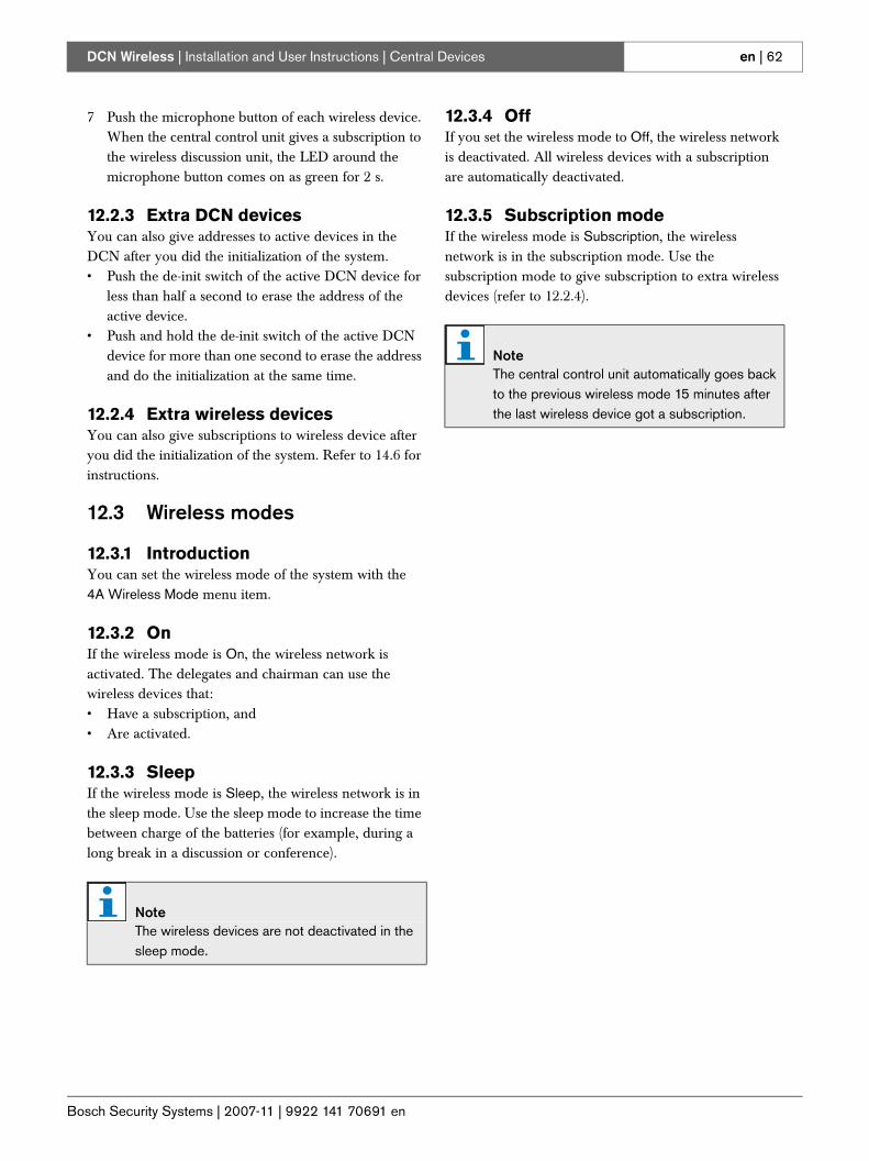
Bosch Security Systems | 2007-11 | 9922 141 70691 en
DCN Wireless | Installation and User Instructions | Central Devices en | 62
7 Push the microphone button of each wireless device. When the central control unit gives a subscription to the wireless discussion unit, the LED around the microphone button comes on as green for 2 s.
12.2.3 Extra DCN devicesYou can also give addresses to active devices in the DCN after you did the initialization of the system.• Push the de-init switch of the active DCN device for
less than half a second to erase the address of the active device.
• Push and hold the de-init switch of the active DCN device for more than one second to erase the address and do the initialization at the same time.
12.2.4 Extra wireless devicesYou can also give subscriptions to wireless device after you did the initialization of the system. Refer to 14.6 for instructions.
12.3 Wireless modes
12.3.1 IntroductionYou can set the wireless mode of the system with the 4A Wireless Mode menu item.
12.3.2 OnIf the wireless mode is On, the wireless network is activated. The delegates and chairman can use the wireless devices that:• Have a subscription, and• Are activated.
12.3.3 SleepIf the wireless mode is Sleep, the wireless network is in the sleep mode. Use the sleep mode to increase the time between charge of the batteries (for example, during a long break in a discussion or conference).
12.3.4 OffIf you set the wireless mode to Off, the wireless network is deactivated. All wireless devices with a subscription are automatically deactivated.
12.3.5 Subscription modeIf the wireless mode is Subscription, the wireless network is in the subscription mode. Use the subscription mode to give subscription to extra wireless devices (refer to 12.2.4).
NoteThe wireless devices are not deactivated in the sleep mode.
NoteThe central control unit automatically goes back to the previous wireless mode 15 minutes after the last wireless device got a subscription.
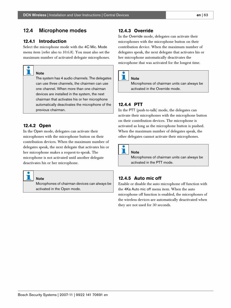
Bosch Security Systems | 2007-11 | 9922 141 70691 en
DCN Wireless | Installation and User Instructions | Central Devices en | 63
12.4 Microphone modes
12.4.1 IntroductionSelect the microphone mode with the 4C Mic. Mode menu item (refer also to 10.6.8). You must also set the maximum number of activated delegate microphones.
12.4.2 OpenIn the Open mode, delegates can activate their microphones with the microphone button on their contribution devices. When the maximum number of delegates speak, the next delegate that activates his or her microphone makes a request-to-speak. The microphone is not activated until another delegate deactivates his or her microphone.
12.4.3 OverrideIn the Override mode, delegates can activate their microphones with the microphone button on their contribution device. When the maximum number of delegates speak, the next delegate that activates his or her microphone automatically deactivates the microphone that was activated for the longest time.
12.4.4 PTTIn the PTT (push-to-talk) mode, the delegates can activate their microphones with the microphone button on their contribution devices. The microphone is activated as long as the microphone button is pushed. When the maximum number of delegates speak, the other delegates cannot activate their microphones.
12.4.5 Auto mic offEnable or disable the auto microphone off function with the 4Ka Auto mic off menu item. When the auto microphone off function is enabled, the microphones of the wireless devices are automatically deactivated when they are not used for 30 seconds.
NoteThe system has 4 audio channels. The delegates can use three channels, the chairmen can use one channel. When more than one chairman devices are installed in the system, the next chairman that activates his or her microphone automatically deactivates the microphone of the previous chairman.
NoteMicrophones of chairman devices can always be activated in the Open mode.
NoteMicrophones of chairman units can always be activated in the Override mode.
NoteMicrophones of chairman units can always be activated in the PTT mode.
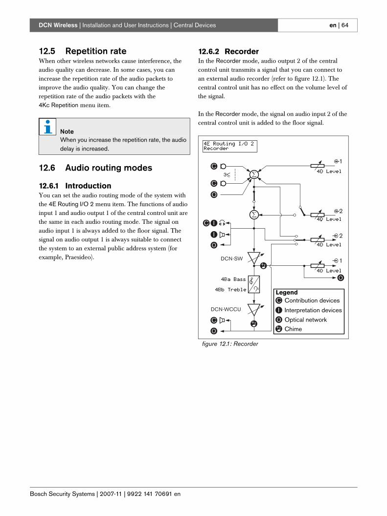
Bosch Security Systems | 2007-11 | 9922 141 70691 en
DCN Wireless | Installation and User Instructions | Central Devices en | 64
12.5 Repetition rateWhen other wireless networks cause interference, the audio quality can decrease. In some cases, you can increase the repetition rate of the audio packets to improve the audio quality. You can change the repetition rate of the audio packets with the 4Kc Repetition menu item.
12.6 Audio routing modes
12.6.1 IntroductionYou can set the audio routing mode of the system with the 4E Routing I/O 2 menu item. The functions of audio input 1 and audio output 1 of the central control unit are the same in each audio routing mode. The signal on audio input 1 is always added to the floor signal. The signal on audio output 1 is always suitable to connect the system to an external public address system (for example, Praesideo).
12.6.2 RecorderIn the Recorder mode, audio output 2 of the central control unit transmits a signal that you can connect to an external audio recorder (refer to figure 12.1). The central control unit has no effect on the volume level of the signal.
In the Recorder mode, the signal on audio input 2 of the central control unit is added to the floor signal.
NoteWhen you increase the repetition rate, the audio delay is increased.
figure 12.1: Recorder
DCN-WCCU
DCN-SW
3<
1
2
2
1C
C
I
I
C
Optical network
Interpretation devices
C Contribution devicesLegend
Chime
I
C
O
+
++
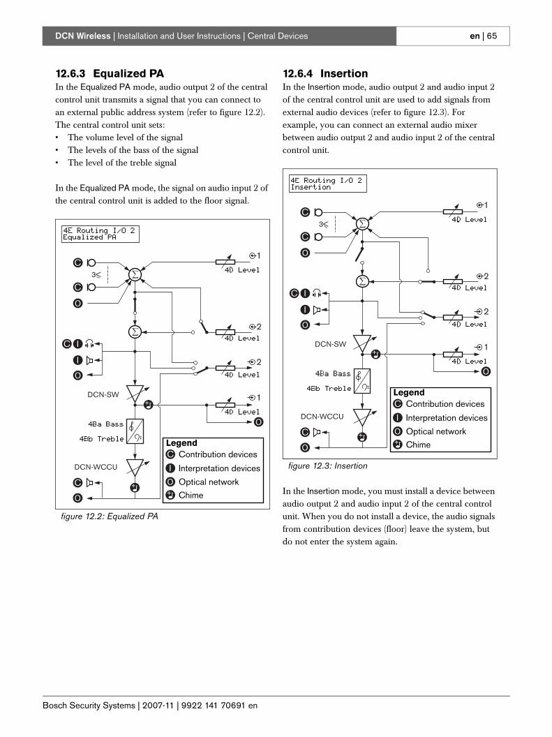
Bosch Security Systems | 2007-11 | 9922 141 70691 en
DCN Wireless | Installation and User Instructions | Central Devices en | 65
12.6.3 Equalized PAIn the Equalized PA mode, audio output 2 of the central control unit transmits a signal that you can connect to an external public address system (refer to figure 12.2). The central control unit sets:• The volume level of the signal• The levels of the bass of the signal• The level of the treble signal
In the Equalized PA mode, the signal on audio input 2 of the central control unit is added to the floor signal.
12.6.4 InsertionIn the Insertion mode, audio output 2 and audio input 2 of the central control unit are used to add signals from external audio devices (refer to figure 12.3). For example, you can connect an external audio mixer between audio output 2 and audio input 2 of the central control unit.
In the Insertion mode, you must install a device between audio output 2 and audio input 2 of the central control unit. When you do not install a device, the audio signals from contribution devices (floor) leave the system, but do not enter the system again.
figure 12.2: Equalized PA
DCN-WCCU
DCN-SW
3<
1
2
2
1C
C
I
I
C
Optical network
Interpretation devices
C Contribution devicesLegend
Chime
I
C
+
++
figure 12.3: Insertion
DCN-WCCU
DCN-SW
3<
1
2
2
1C
C
I
I
C
Optical network
Interpretation devices
C Contribution devicesLegend
Chime
I
C
+
++
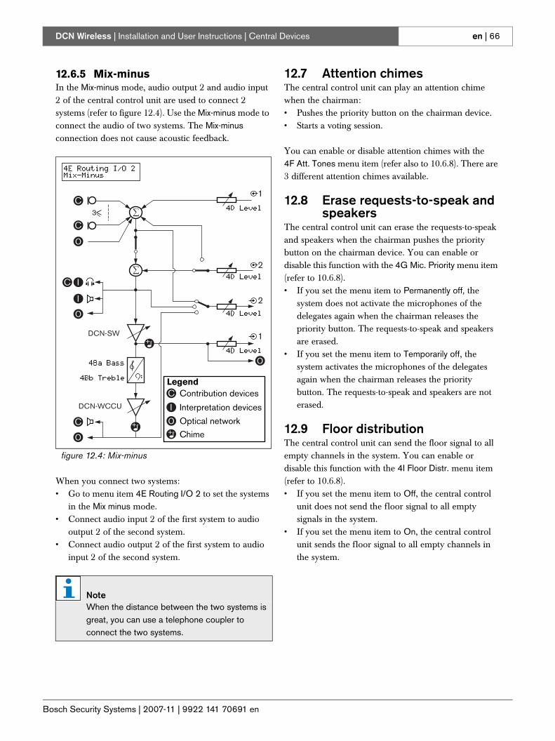
Bosch Security Systems | 2007-11 | 9922 141 70691 en
DCN Wireless | Installation and User Instructions | Central Devices en | 66
12.6.5 Mix-minusIn the Mix-minus mode, audio output 2 and audio input 2 of the central control unit are used to connect 2 systems (refer to figure 12.4). Use the Mix-minus mode to connect the audio of two systems. The Mix-minus connection does not cause acoustic feedback.
When you connect two systems:• Go to menu item 4E Routing I/O 2 to set the systems
in the Mix minus mode.• Connect audio input 2 of the first system to audio
output 2 of the second system.• Connect audio output 2 of the first system to audio
input 2 of the second system.
12.7 Attention chimesThe central control unit can play an attention chime when the chairman:• Pushes the priority button on the chairman device.• Starts a voting session.
You can enable or disable attention chimes with the 4F Att. Tones menu item (refer also to 10.6.8). There are 3 different attention chimes available.
12.8 Erase requests-to-speak and speakers
The central control unit can erase the requests-to-speak and speakers when the chairman pushes the priority button on the chairman device. You can enable or disable this function with the 4G Mic. Priority menu item (refer to 10.6.8).• If you set the menu item to Permanently off, the
system does not activate the microphones of the delegates again when the chairman releases the priority button. The requests-to-speak and speakers are erased.
• If you set the menu item to Temporarily off, the system activates the microphones of the delegates again when the chairman releases the priority button. The requests-to-speak and speakers are not erased.
12.9 Floor distributionThe central control unit can send the floor signal to all empty channels in the system. You can enable or disable this function with the 4I Floor Distr. menu item (refer to 10.6.8).• If you set the menu item to Off, the central control
unit does not send the floor signal to all empty signals in the system.
• If you set the menu item to On, the central control unit sends the floor signal to all empty channels in the system.
figure 12.4: Mix-minus
NoteWhen the distance between the two systems is great, you can use a telephone coupler to connect the two systems.
DCN-WCCU
DCN-SW
3<
1
2
2
1C
C
I
I
C
Optical network
Interpretation devices
C Contribution devicesLegend
Chime
I
C
+
++
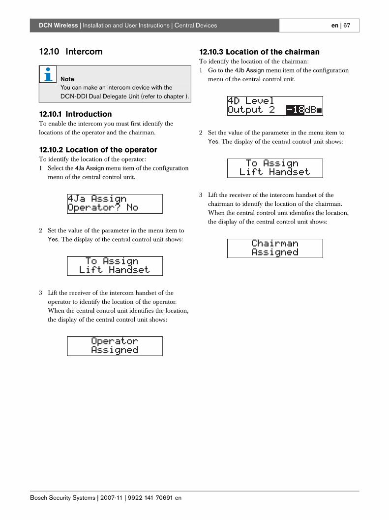
Bosch Security Systems | 2007-11 | 9922 141 70691 en
DCN Wireless | Installation and User Instructions | Central Devices en | 67
12.10 Intercom
12.10.1 IntroductionTo enable the intercom you must first identify the locations of the operator and the chairman.
12.10.2 Location of the operatorTo identify the location of the operator:1 Select the 4Ja Assign menu item of the configuration
menu of the central control unit.
2 Set the value of the parameter in the menu item to Yes. The display of the central control unit shows:
3 Lift the receiver of the intercom handset of the operator to identify the location of the operator. When the central control unit identifies the location, the display of the central control unit shows:
12.10.3 Location of the chairmanTo identify the location of the chairman:1 Go to the 4Jb Assign menu item of the configuration
menu of the central control unit.
2 Set the value of the parameter in the menu item to Yes. The display of the central control unit shows:
3 Lift the receiver of the intercom handset of the chairman to identify the location of the chairman. When the central control unit identifies the location, the display of the central control unit shows:
NoteYou can make an intercom device with the DCN-DDI Dual Delegate Unit (refer to chapter ).
Bosch Security Systems | 2007-11 | 9922 141 70691 en
DCN Wireless | Installation and User Instructions | Central Devices en | 68
13 System operation
13.1 Start the systemBefore starting the system, make sure:• the system is correctly installed.• the required number of wireless discussion units
have been subscribed.
Do as follows:1 Push the on/off switch on the central control unit.
The display comes on. All devices in the DCN and optical network are activated.
2 Install the battery packs in the wireless discussion units.
3 Push the microphone buttons on the wireless discussion units to activate the wireless discussion units. The LED around the microphone button comes on as yellow for 250 milliseconds (if the software version of the wireless discussion unit is lower than 2.35, the LED around the microphone button comes on as green for 2 seconds).
• If all LEDs of the wireless discussion unit are off, the wireless discussion unit is activated, and ready to use.
• If the LED around the microphone button stays on as yellow, and the indicator ring of the microphone comes on as red, the wireless discussion unit cannot find the subscribed wireless network. If the wireless network is found within 15 minutes, the wireless discussion unit connects. If not, the wireless discussion unit automatically deactivates (if the software version of the wireless discussion unit is lower than 2.35, the LED around the microphone button alternates red and yellow for 5 seconds to indicate that the wireless discussion unit cannot find the subscribed wireless network. If the wireless network is found within 5 seconds, the wireless discussion unit connects. If not, the wireless discussion unit automatically deactivates).
• If you want to use the wireless discussion unit in a new system, but it is already subscribed to another system (see previous bullet point), you must first deinitialize the unit (refer to section 14.6.3). After the unit has been de-initialization it must be subscribed to the new system (refer to section 14.6.2).
13.2 Stop the system
Do as follows:1 Select the 4A Wireless Mode menu item of the
configuration menu of the central control unit.2 Set the value of the parameter in the menu item to
Off. All wireless discussion units are deactivated.3 Push the on/off switch of the central control unit.
The display goes off. All devices in the DCN and the optical network are deactivated.
NoteIf necessary, charge the battery packs.
Bosch Security Systems | 2007-11 | 9922 141 70691 en
DCN Wireless | Installation and User Instructions | Contribution Devices en | 69
Section 3 - Contribution Devices
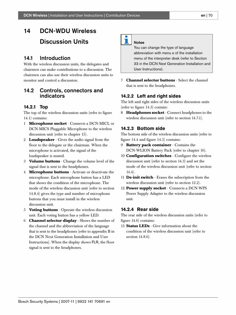
Bosch Security Systems | 2007-11 | 9922 141 70691 en
DCN Wireless | Installation and User Instructions | Contribution Devices en | 70
14 DCN-WDU Wireless
Discussion Units
14.1 IntroductionWith the wireless discussion units, the delegates and chairmen can make contributions to a discussion. The chairmen can also use their wireless discussion units to monitor and control a discussion.
14.2 Controls, connectors and indicators
14.2.1 TopThe top of the wireless discussion units (refer to figure 14.1) contains:1 Microphone socket - Connects a DCN-MICL or
DCN-MICS Pluggable Microphone to the wireless discussion unit (refer to chapter 15).
2 Loudspeaker - Gives the audio signal from the floor to the delegate or the chairman. When the microphone is activated, the signal of the loudspeaker is muted.
3 Volume buttons - Change the volume level of the signal that is sent to the headphones.
4 Microphone buttons - Activate or deactivate the microphone. Each microphone button has a LED that shows the condition of the microphone. The mode of the wireless discussion unit (refer to section 14.8.4) gives the type and number of microphone buttons that you must install in the wireless discussion unit.
5 Voting buttons - Operate the wireless discussion unit. Each voting button has a yellow LED.
6 Channel selector display - Shows the number of the channel and the abbreviation of the language that is sent to the headphones (refer to appendix B in the DCN Next Generation Installation and User Instructions). When the display shows FLR, the floor signal is sent to the headphones.
7 Channel selector buttons - Select the channel that is sent to the headphones.
14.2.2 Left and right sidesThe left and right sides of the wireless discussion units (refer to figure 14.3) contain:8 Headphones socket - Connect headphones to the
wireless discussion unit (refer to section 14.7.1).
14.2.3 Bottom sideThe bottom side of the wireless discussion units (refer to figure 14.4 and figure 14.5) contains:9 Battery pack container - Contains the
DCN-WLION Battery Pack (refer to chapter 16).10 Configuration switches - Configure the wireless
discussion unit (refer to section 14.3) and set the mode of the wireless discussion unit (refer to section 14.4).
11 De-init switch - Erases the subscription from the wireless discussion unit (refer to section 12.2).
12 Power supply socket - Connects a DCN-WPS Power Supply Adapter to the wireless discussion unit.
14.2.4 Rear sideThe rear side of the wireless discussion units (refer to figure 14.6) contains:13 Status LEDs - Give information about the
condition of the wireless discussion unit (refer to section 14.8.6).
NoteeYou can change the type of language abbreviation with menu e of the installation menu of the interpreter desk (refer to Section 33 in the DCN Next Generation Installation and User Instructions).
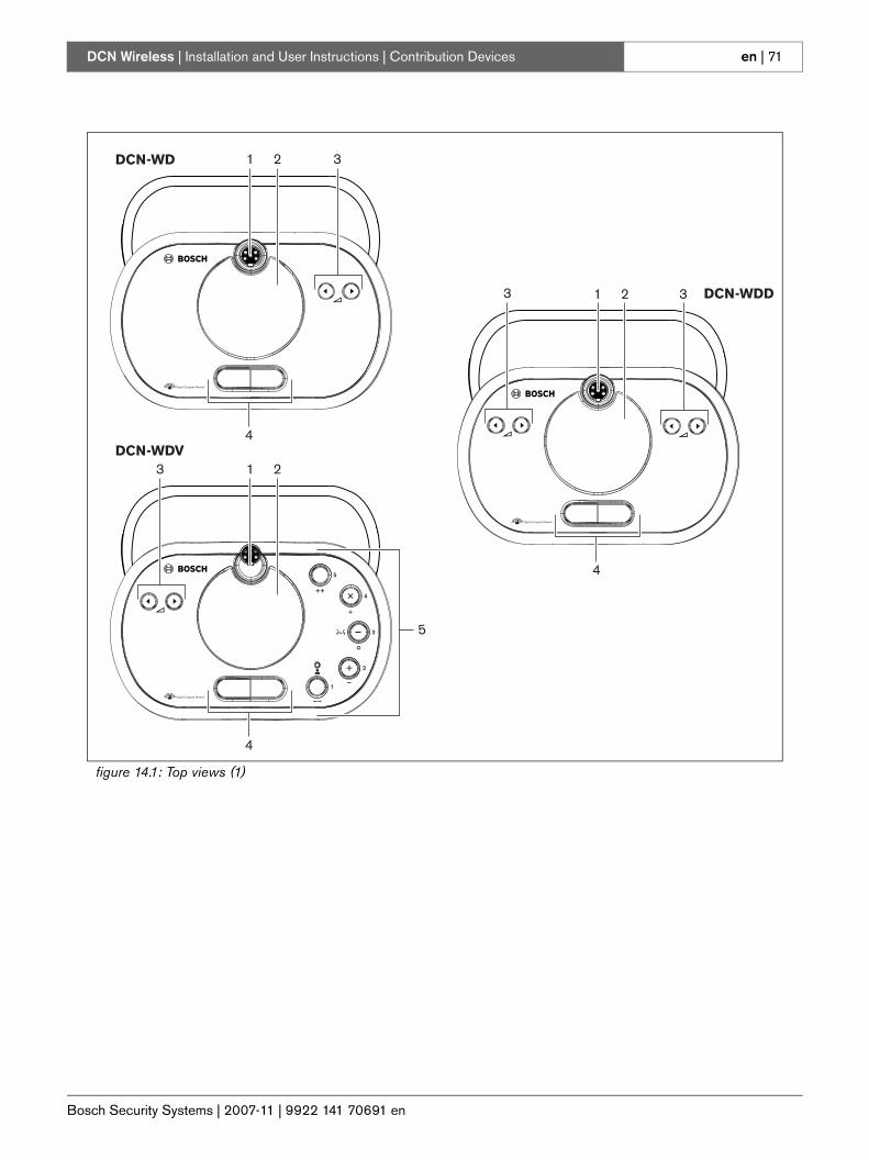
Bosch Security Systems | 2007-11 | 9922 141 70691 en
DCN Wireless | Installation and User Instructions | Contribution Devices en | 71
figure 14.1: Top views (1)
1 2 3
4
DCN-WD
DCN-WDV
DCN-WDD1 2 3
4
1 23
4
5
3
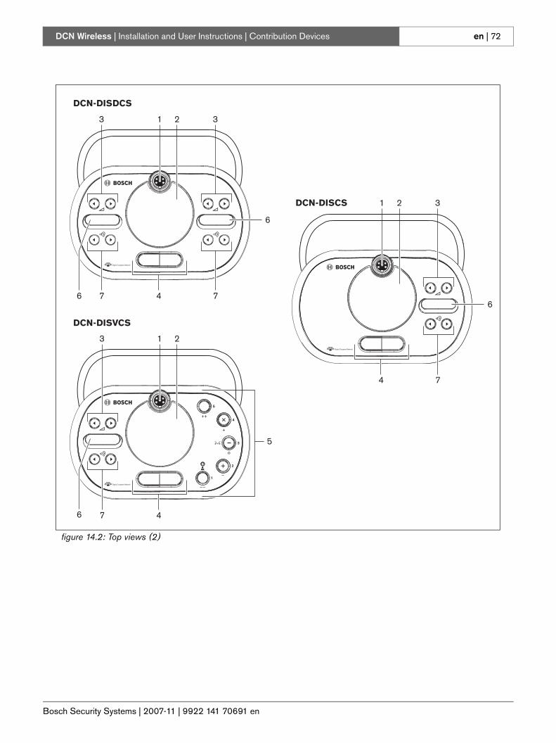
Bosch Security Systems | 2007-11 | 9922 141 70691 en
DCN Wireless | Installation and User Instructions | Contribution Devices en | 72
figure 14.2: Top views (2)
1 2 3
4
DCN-DISDCS
DCN-DISVCS
1 23
7 4
5
7
3
76
6
6
74
1 2
6
3DCN-DISCS
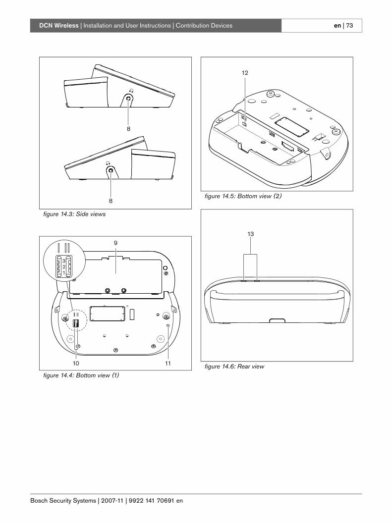
Bosch Security Systems | 2007-11 | 9922 141 70691 en
DCN Wireless | Installation and User Instructions | Contribution Devices en | 73
figure 14.3: Side views
figure 14.4: Bottom view (1)
8
8
9
321
10 11
figure 14.5: Bottom view (2)
figure 14.6: Rear view
12
13
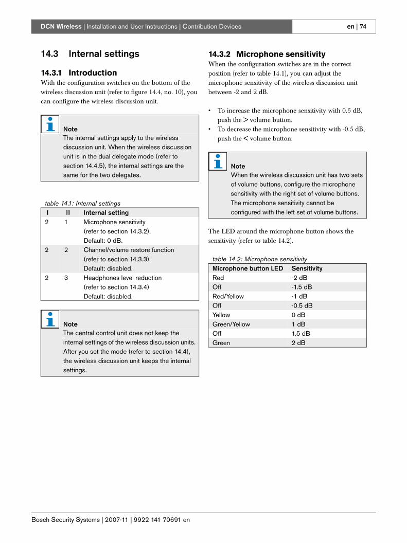
Bosch Security Systems | 2007-11 | 9922 141 70691 en
DCN Wireless | Installation and User Instructions | Contribution Devices en | 74
14.3 Internal settings
14.3.1 IntroductionWith the configuration switches on the bottom of the wireless discussion unit (refer to figure 14.4, no. 10), you can configure the wireless discussion unit.
14.3.2 Microphone sensitivityWhen the configuration switches are in the correct position (refer to table 14.1), you can adjust the microphone sensitivity of the wireless discussion unit between -2 and 2 dB.
• To increase the microphone sensitivity with 0.5 dB, push the > volume button.
• To decrease the microphone sensitivity with -0.5 dB, push the < volume button.
The LED around the microphone button shows the sensitivity (refer to table 14.2).
NoteThe internal settings apply to the wireless discussion unit. When the wireless discussion unit is in the dual delegate mode (refer to section 14.4.5), the internal settings are the same for the two delegates.
table 14.1: Internal settings I II Internal setting2 1 Microphone sensitivity
(refer to section 14.3.2). Default: 0 dB.
2 2 Channel/volume restore function(refer to section 14.3.3).Default: disabled.
2 3 Headphones level reduction(refer to section 14.3.4)Default: disabled.
NoteThe central control unit does not keep the internal settings of the wireless discussion units. After you set the mode (refer to section 14.4), the wireless discussion unit keeps the internal settings.
NoteWhen the wireless discussion unit has two sets of volume buttons, configure the microphone sensitivity with the right set of volume buttons. The microphone sensitivity cannot be configured with the left set of volume buttons.
table 14.2: Microphone sensitivity Microphone button LED SensitivityRed -2 dBOff -1.5 dBRed/Yellow -1 dBOff -0.5 dBYellow 0 dBGreen/Yellow 1 dBOff 1.5 dBGreen 2 dB
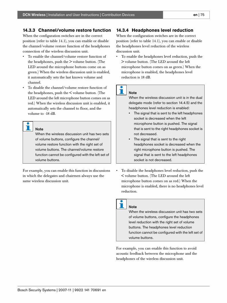
Bosch Security Systems | 2007-11 | 9922 141 70691 en
DCN Wireless | Installation and User Instructions | Contribution Devices en | 75
14.3.3 Channel/volume restore functionWhen the configuration switches are in the correct position (refer to table 14.1), you can enable or disable the channel/volume restore function of the headphones connection of the wireless discussion unit.• To enable the channel/volume restore function of
the headphones, push the > volume button. (The LED around the microphone buttons come on as green.) When the wireless discussion unit is enabled, it automatically sets the last known volume and channel.
• To disable the channel/volume restore function of the headphones, push the < volume button. (The LED around the left microphone button comes on as red.) When the wireless discussion unit is enabled, it automatically sets the channel to floor, and the volume to -18 dB.
For example, you can enable this function in discussions in which the delegates and chairmen always use the same wireless discussion unit.
14.3.4 Headphones level reductionWhen the configuration switches are in the correct position (refer to table 14.1), you can enable or disable the headphones level reduction of the wireless discussion unit.• To enable the headphones level reduction, push the
> volume button. (The LED around the left microphone button comes on as green.) When the microphone is enabled, the headphones level reduction is 18 dB.
• To disable the headphones level reduction, push the < volume button. (The LED around the left microphone button comes on as red.) When the microphone is enabled, there is no headphones level reduction.
For example, you can enable this function to avoid acoustic feedback between the microphone and the headphones of the wireless discussion unit.
NoteWhen the wireless discussion unit has two sets of volume buttons, configure the channel/volume restore function with the right set of volume buttons. The channel/volume restore function cannot be configured with the left set of volume buttons.
NoteWhen the wireless discussion unit is in the dual delegate mode (refer to section 14.4.5) and the headphones level reduction is enabled:• The signal that is sent to the left headphones
socket is decreased when the left microphone button is pushed. The signal that is sent to the right headphones socket is not decreased.
• The signal that is sent to the right headphones socket is decreased when the right microphone button is pushed. The signal that is sent to the left headphones socket is not decreased.
NoteWhen the wireless discussion unit has two sets of volume buttons, configure the headphones level reduction with the right set of volume buttons. The headphones level reduction function cannot be configured with the left set of volume buttons.
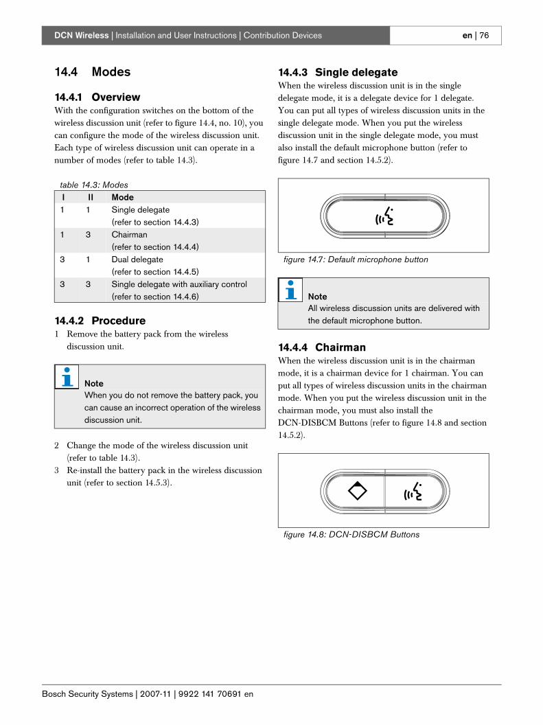
Bosch Security Systems | 2007-11 | 9922 141 70691 en
DCN Wireless | Installation and User Instructions | Contribution Devices en | 76
14.4 Modes
14.4.1 OverviewWith the configuration switches on the bottom of the wireless discussion unit (refer to figure 14.4, no. 10), you can configure the mode of the wireless discussion unit. Each type of wireless discussion unit can operate in a number of modes (refer to table 14.3).
14.4.2 Procedure1 Remove the battery pack from the wireless
discussion unit.
2 Change the mode of the wireless discussion unit (refer to table 14.3).
3 Re-install the battery pack in the wireless discussion unit (refer to section 14.5.3).
14.4.3 Single delegateWhen the wireless discussion unit is in the single delegate mode, it is a delegate device for 1 delegate. You can put all types of wireless discussion units in the single delegate mode. When you put the wireless discussion unit in the single delegate mode, you must also install the default microphone button (refer to figure 14.7 and section 14.5.2).
14.4.4 ChairmanWhen the wireless discussion unit is in the chairman mode, it is a chairman device for 1 chairman. You can put all types of wireless discussion units in the chairman mode. When you put the wireless discussion unit in the chairman mode, you must also install the DCN-DISBCM Buttons (refer to figure 14.8 and section 14.5.2).
table 14.3: Modes I II Mode1 1 Single delegate
(refer to section 14.4.3)1 3 Chairman
(refer to section 14.4.4)3 1 Dual delegate
(refer to section 14.4.5)3 3 Single delegate with auxiliary control
(refer to section 14.4.6)
NoteWhen you do not remove the battery pack, you can cause an incorrect operation of the wireless discussion unit.
figure 14.7: Default microphone button
NoteAll wireless discussion units are delivered with the default microphone button.
figure 14.8: DCN-DISBCM Buttons
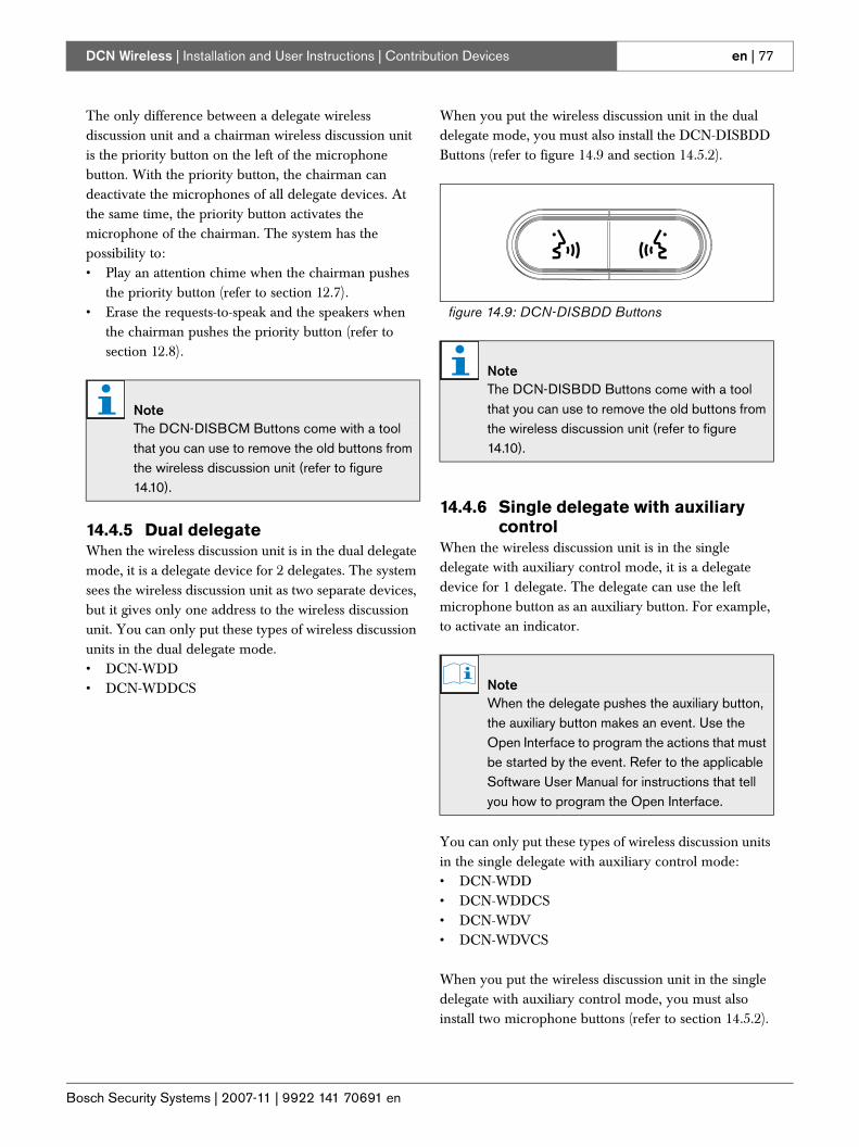
Bosch Security Systems | 2007-11 | 9922 141 70691 en
DCN Wireless | Installation and User Instructions | Contribution Devices en | 77
The only difference between a delegate wireless discussion unit and a chairman wireless discussion unit is the priority button on the left of the microphone button. With the priority button, the chairman can deactivate the microphones of all delegate devices. At the same time, the priority button activates the microphone of the chairman. The system has the possibility to:• Play an attention chime when the chairman pushes
the priority button (refer to section 12.7).• Erase the requests-to-speak and the speakers when
the chairman pushes the priority button (refer to section 12.8).
14.4.5 Dual delegateWhen the wireless discussion unit is in the dual delegate mode, it is a delegate device for 2 delegates. The system sees the wireless discussion unit as two separate devices, but it gives only one address to the wireless discussion unit. You can only put these types of wireless discussion units in the dual delegate mode.• DCN-WDD• DCN-WDDCS
When you put the wireless discussion unit in the dual delegate mode, you must also install the DCN-DISBDD Buttons (refer to figure 14.9 and section 14.5.2).
14.4.6 Single delegate with auxiliary control
When the wireless discussion unit is in the single delegate with auxiliary control mode, it is a delegate device for 1 delegate. The delegate can use the left microphone button as an auxiliary button. For example, to activate an indicator.
You can only put these types of wireless discussion units in the single delegate with auxiliary control mode:• DCN-WDD• DCN-WDDCS• DCN-WDV• DCN-WDVCS
When you put the wireless discussion unit in the single delegate with auxiliary control mode, you must also install two microphone buttons (refer to section 14.5.2).
NoteThe DCN-DISBCM Buttons come with a tool that you can use to remove the old buttons from the wireless discussion unit (refer to figure 14.10).
figure 14.9: DCN-DISBDD Buttons
NoteThe DCN-DISBDD Buttons come with a tool that you can use to remove the old buttons from the wireless discussion unit (refer to figure 14.10).
NoteWhen the delegate pushes the auxiliary button, the auxiliary button makes an event. Use the Open Interface to program the actions that must be started by the event. Refer to the applicable Software User Manual for instructions that tell you how to program the Open Interface.
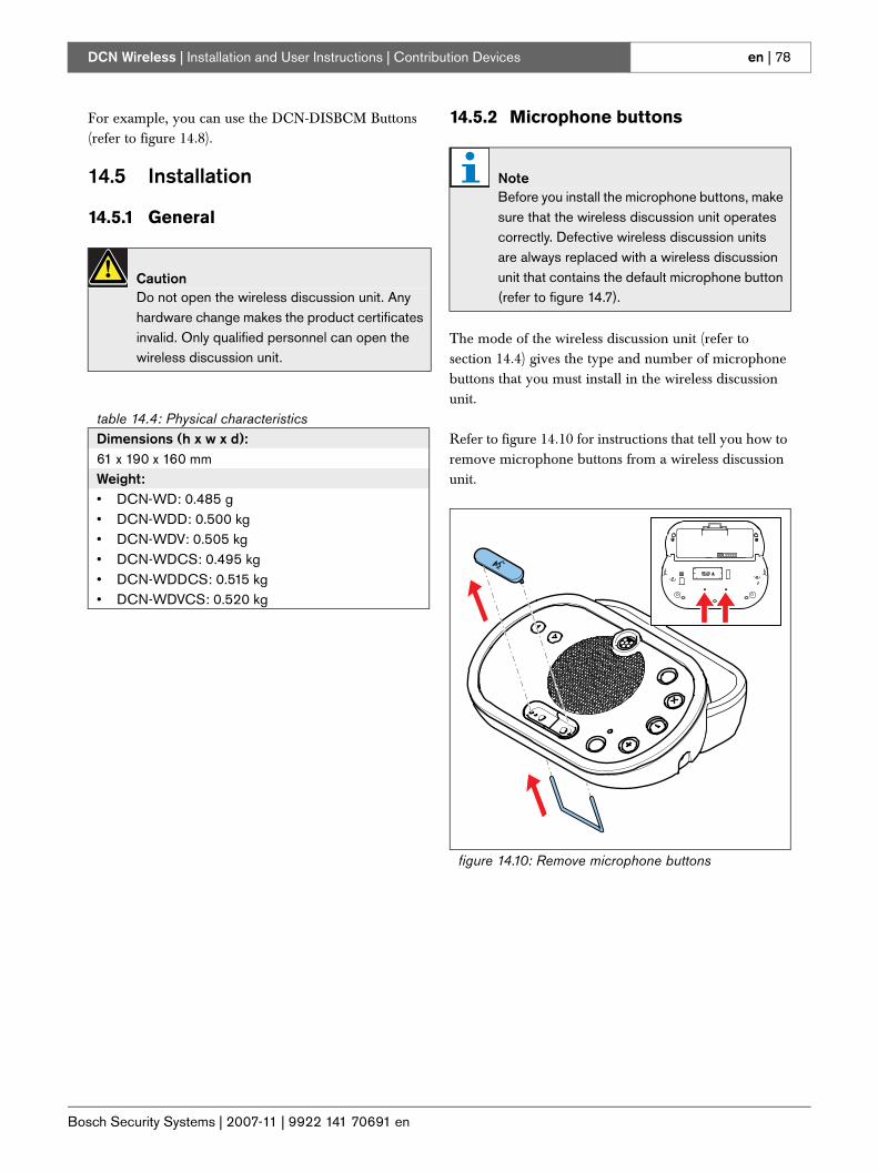
Bosch Security Systems | 2007-11 | 9922 141 70691 en
DCN Wireless | Installation and User Instructions | Contribution Devices en | 78
For example, you can use the DCN-DISBCM Buttons (refer to figure 14.8).
14.5 Installation
14.5.1 General
14.5.2 Microphone buttons
The mode of the wireless discussion unit (refer to section 14.4) gives the type and number of microphone buttons that you must install in the wireless discussion unit.
Refer to figure 14.10 for instructions that tell you how to remove microphone buttons from a wireless discussion unit.
CautionDo not open the wireless discussion unit. Any hardware change makes the product certificates invalid. Only qualified personnel can open the wireless discussion unit.
table 14.4: Physical characteristicsDimensions (h x w x d):61 x 190 x 160 mmWeight:• DCN-WD: 0.485 g• DCN-WDD: 0.500 kg• DCN-WDV: 0.505 kg• DCN-WDCS: 0.495 kg• DCN-WDDCS: 0.515 kg• DCN-WDVCS: 0.520 kg
NoteBefore you install the microphone buttons, make sure that the wireless discussion unit operates correctly. Defective wireless discussion units are always replaced with a wireless discussion unit that contains the default microphone button (refer to figure 14.7).
figure 14.10: Remove microphone buttons
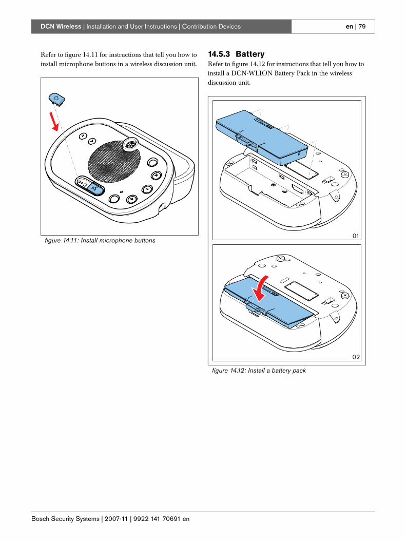
Bosch Security Systems | 2007-11 | 9922 141 70691 en
DCN Wireless | Installation and User Instructions | Contribution Devices en | 79
Refer to figure 14.11 for instructions that tell you how to install microphone buttons in a wireless discussion unit.
14.5.3 BatteryRefer to figure 14.12 for instructions that tell you how to install a DCN-WLION Battery Pack in the wireless discussion unit.
figure 14.11: Install microphone buttons
figure 14.12: Install a battery pack
02
01
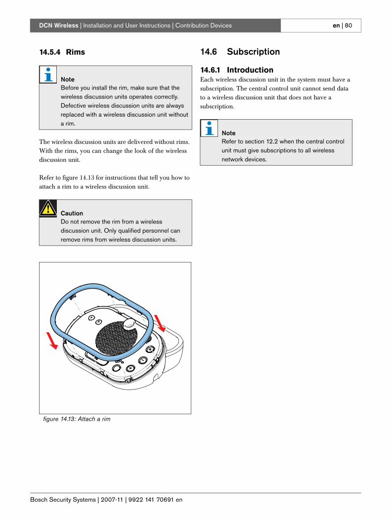
Bosch Security Systems | 2007-11 | 9922 141 70691 en
DCN Wireless | Installation and User Instructions | Contribution Devices en | 80
14.5.4 Rims
The wireless discussion units are delivered without rims. With the rims, you can change the look of the wireless discussion unit.
Refer to figure 14.13 for instructions that tell you how to attach a rim to a wireless discussion unit.
14.6 Subscription
14.6.1 IntroductionEach wireless discussion unit in the system must have a subscription. The central control unit cannot send data to a wireless discussion unit that does not have a subscription.
NoteBefore you install the rim, make sure that the wireless discussion units operates correctly. Defective wireless discussion units are always replaced with a wireless discussion unit without a rim.
CautionDo not remove the rim from a wireless discussion unit. Only qualified personnel can remove rims from wireless discussion units.
figure 14.13: Attach a rim
NoteRefer to section 12.2 when the central control unit must give subscriptions to all wireless network devices.
Bosch Security Systems | 2007-11 | 9922 141 70691 en
DCN Wireless | Installation and User Instructions | Contribution Devices en | 81
14.6.2 Procedure
The procedure below is applicable for wireless discussion devices without a subscription. If the wireless discussion unit already has a subscription, first erase the subscription (refer to section 14.6.3).
Do as follows:1 Set the wireless mode of the system to Subscription
(refer to section 12.3.5).2 Insert charged batteries into the wireless discussion
units.3 Push the microphone button of the wireless
discussion unit. All LEDs of the wireless discussion unit come on and stay on, and the indicator ring of the microphone comes on as red.
4 Push the microphone button of the wireless discussion unit for a second time. The unit will try to subscribe. If subscription is successful, all LEDs of the wireless discussion unit, and the indicator ring of the microphone go off (if the software version of the wireless discussion unit is lower than 2.35, all LEDs go off after 2 seconds, and the LED around the microphone is green for 5 seconds indicating that the subscription was successful. A second push on the microphone button, as required for units with software version 2.35 or higher, is not required).
• If after pushing the microphone button for a second time, all LEDs around the microphone button and the indicator ring of the microphone come on again, the wireless discussion unit is either not within range of the wireless network, or the wireless mode is not set to Subscription (if the software version of the wireless discussion unit is lower than 2.35, and after pushing the microphone button for the first time, the ring around the microphone button alternates red and green for 5 seconds, the unit is either: not within range of the wireless network, the wireless mode is not set to Subscription, or the language distribution is enabled). Refer to the note under Limit 4 in section 1.
• If after pushing the microphone button for the first time, the ring around the microphone button is yellow for 250 milliseconds and then goes off, the wireless discussion unit was already subscribed to this system - you did not have to put the system in subscription mode. Instead switch on the unit as described in section 13.1 (if the software version of the wireless discussion unit is lower than 2.35, the ring around the microphone button is green for 2 seconds).
• If after pushing the microphone button for the first time, the yellow LEDs around the microphone button, and the red indicator ring of the microphone are on, the wireless discussion unit is already subscribed to a system, but is not within range of this system. If the unit cannot find the system within 15 minutes, it will automatically switch off (if the software version of the wireless discussion unit is lower than 2.35, the ring around the microphone button alternates red and yellow for 5 seconds, and then the unit automatically switches off).
• If after pushing the microphone button for the first time, the yellow LED comes on for 250 ms and the red microphone indicator comes on and stays on, the wireless discussion unit is already subscribed to the system, but another unit with the same address is already connected. To correct this, de-initialize the unit as described in section 14.6.3, or push the microphone button for a second time. The unit will then de-initialize. If the unit is in range of the wireless network and subscription is enabled, the unit will also subscribe (if the software version of the wireless discussion unit is lower than 2.35, the ring around the microphone button alternates red and yellow for 5 seconds, and then the unit automatically switches off. De-initialize the unit as described in section 14.6.3, and then subscribe the unit again).
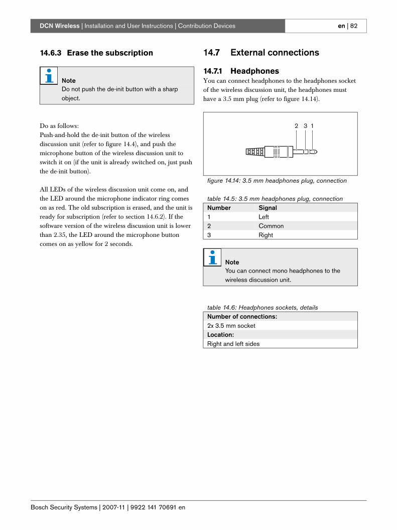
Bosch Security Systems | 2007-11 | 9922 141 70691 en
DCN Wireless | Installation and User Instructions | Contribution Devices en | 82
14.6.3 Erase the subscription
Do as follows:Push-and-hold the de-init button of the wireless discussion unit (refer to figure 14.4), and push the microphone button of the wireless discussion unit to switch it on (if the unit is already switched on, just push the de-init button).
All LEDs of the wireless discussion unit come on, and the LED around the microphone indicator ring comes on as red. The old subscription is erased, and the unit is ready for subscription (refer to section 14.6.2). If the software version of the wireless discussion unit is lower than 2.35, the LED around the microphone button comes on as yellow for 2 seconds.
14.7 External connections
14.7.1 HeadphonesYou can connect headphones to the headphones socket of the wireless discussion unit, the headphones must have a 3.5 mm plug (refer to figure 14.14).
NoteDo not push the de-init button with a sharp object.
figure 14.14: 3.5 mm headphones plug, connection
table 14.5: 3.5 mm headphones plug, connectionNumber Signal1 Left2 Common3 Right
NoteYou can connect mono headphones to the wireless discussion unit.
table 14.6: Headphones sockets, detailsNumber of connections:2x 3.5 mm socketLocation:Right and left sides
2 3 1
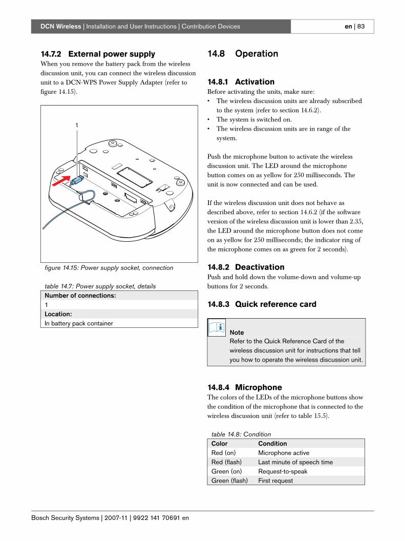
Bosch Security Systems | 2007-11 | 9922 141 70691 en
DCN Wireless | Installation and User Instructions | Contribution Devices en | 83
14.7.2 External power supplyWhen you remove the battery pack from the wireless discussion unit, you can connect the wireless discussion unit to a DCN-WPS Power Supply Adapter (refer to figure 14.15).
14.8 Operation
14.8.1 ActivationBefore activating the units, make sure:• The wireless discussion units are already subscribed
to the system (refer to section 14.6.2). • The system is switched on.• The wireless discussion units are in range of the
system.
Push the microphone button to activate the wireless discussion unit. The LED around the microphone button comes on as yellow for 250 milliseconds. The unit is now connected and can be used.
If the wireless discussion unit does not behave as described above, refer to section 14.6.2 (if the software version of the wireless discussion unit is lower than 2.35, the LED around the microphone button does not come on as yellow for 250 milliseconds; the indicator ring of the microphone comes on as green for 2 seconds).
14.8.2 DeactivationPush and hold down the volume-down and volume-up buttons for 2 seconds.
14.8.3 Quick reference card
14.8.4 MicrophoneThe colors of the LEDs of the microphone buttons show the condition of the microphone that is connected to the wireless discussion unit (refer to table 15.5).
figure 14.15: Power supply socket, connection
table 14.7: Power supply socket, detailsNumber of connections:1Location:In battery pack container
1
NoteRefer to the Quick Reference Card of the wireless discussion unit for instructions that tell you how to operate the wireless discussion unit.
table 14.8: ConditionColor ConditionRed (on) Microphone activeRed (flash) Last minute of speech timeGreen (on) Request-to-speakGreen (flash) First request
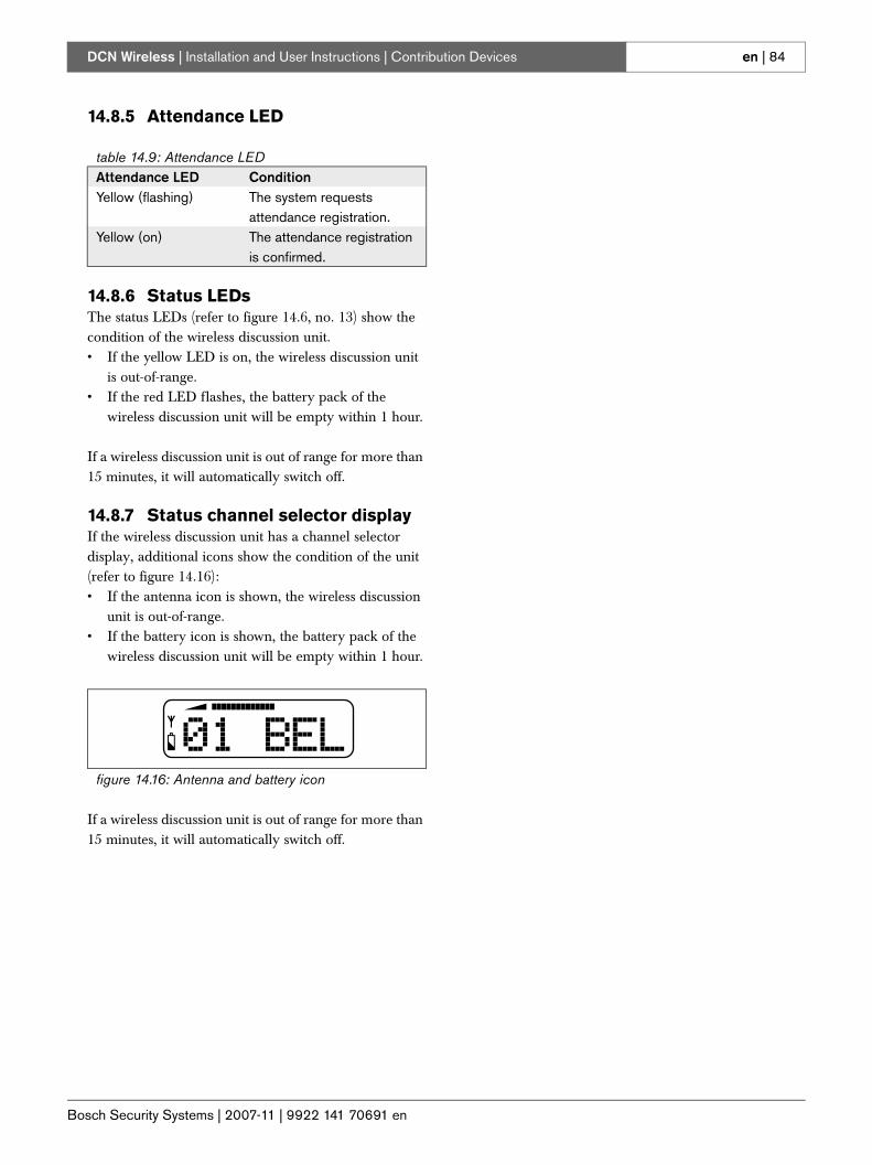
Bosch Security Systems | 2007-11 | 9922 141 70691 en
DCN Wireless | Installation and User Instructions | Contribution Devices en | 84
14.8.5 Attendance LED
14.8.6 Status LEDsThe status LEDs (refer to figure 14.6, no. 13) show the condition of the wireless discussion unit.• If the yellow LED is on, the wireless discussion unit
is out-of-range.• If the red LED flashes, the battery pack of the
wireless discussion unit will be empty within 1 hour.
If a wireless discussion unit is out of range for more than 15 minutes, it will automatically switch off.
14.8.7 Status channel selector displayIf the wireless discussion unit has a channel selector display, additional icons show the condition of the unit (refer to figure 14.16):• If the antenna icon is shown, the wireless discussion
unit is out-of-range.• If the battery icon is shown, the battery pack of the
wireless discussion unit will be empty within 1 hour.
If a wireless discussion unit is out of range for more than 15 minutes, it will automatically switch off.
table 14.9: Attendance LEDAttendance LED ConditionYellow (flashing) The system requests
attendance registration.Yellow (on) The attendance registration
is confirmed.
figure 14.16: Antenna and battery icon
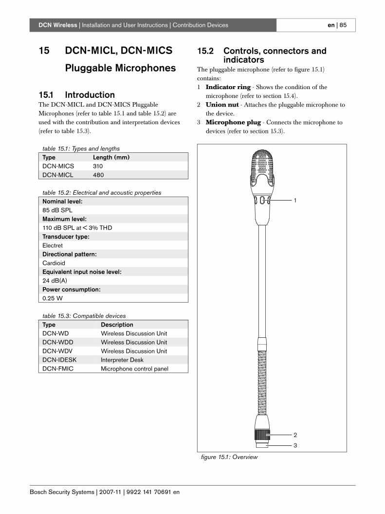
Bosch Security Systems | 2007-11 | 9922 141 70691 en
DCN Wireless | Installation and User Instructions | Contribution Devices en | 85
15 DCN-MICL, DCN-MICS
Pluggable Microphones
15.1 IntroductionThe DCN-MICL and DCN-MICS Pluggable Microphones (refer to table 15.1 and table 15.2) are used with the contribution and interpretation devices (refer to table 15.3).
15.2 Controls, connectors and indicators
The pluggable microphone (refer to figure 15.1) contains:1 Indicator ring - Shows the condition of the
microphone (refer to section 15.4).2 Union nut - Attaches the pluggable microphone to
the device.3 Microphone plug - Connects the microphone to
devices (refer to section 15.3).
table 15.1: Types and lengthsType Length (mm)DCN-MICS 310DCN-MICL 480
table 15.2: Electrical and acoustic propertiesNominal level:85 dB SPLMaximum level:110 dB SPL at < 3% THDTransducer type:ElectretDirectional pattern:CardioidEquivalent input noise level:24 dB(A)Power consumption:0.25 W
table 15.3: Compatible devicesType DescriptionDCN-WD Wireless Discussion UnitDCN-WDD Wireless Discussion UnitDCN-WDV Wireless Discussion UnitDCN-IDESK Interpreter DeskDCN-FMIC Microphone control panel
figure 15.1: Overview
1
2
3
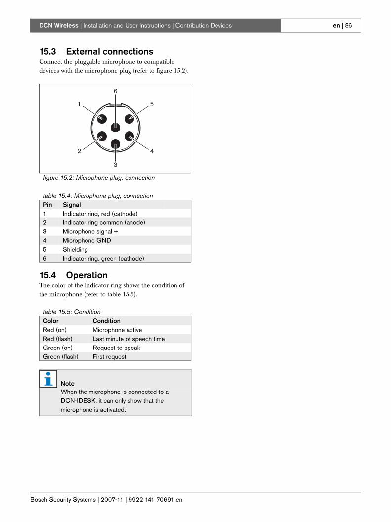
Bosch Security Systems | 2007-11 | 9922 141 70691 en
DCN Wireless | Installation and User Instructions | Contribution Devices en | 86
15.3 External connectionsConnect the pluggable microphone to compatible devices with the microphone plug (refer to figure 15.2).
15.4 OperationThe color of the indicator ring shows the condition of the microphone (refer to table 15.5).
figure 15.2: Microphone plug, connection
table 15.4: Microphone plug, connectionPin Signal1 Indicator ring, red (cathode)2 Indicator ring common (anode)3 Microphone signal +4 Microphone GND5 Shielding6 Indicator ring, green (cathode)
table 15.5: ConditionColor ConditionRed (on) Microphone activeRed (flash) Last minute of speech timeGreen (on) Request-to-speakGreen (flash) First request
NoteWhen the microphone is connected to a DCN-IDESK, it can only show that the microphone is activated.
6
1
2
5
4
3
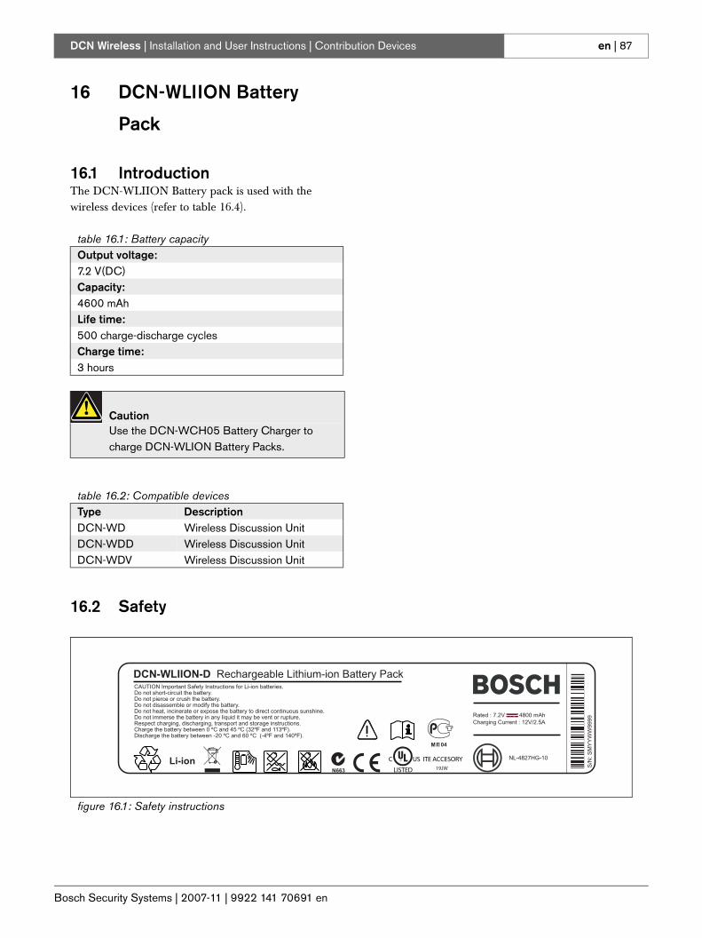
Bosch Security Systems | 2007-11 | 9922 141 70691 en
DCN Wireless | Installation and User Instructions | Contribution Devices en | 87
16 DCN-WLIION Battery
Pack
16.1 IntroductionThe DCN-WLIION Battery pack is used with the wireless devices (refer to table 16.4).
16.2 Safety
table 16.1: Battery capacityOutput voltage:7.2 V(DC)Capacity:4600 mAhLife time:500 charge-discharge cyclesCharge time:3 hours
CautionUse the DCN-WCH05 Battery Charger to charge DCN-WLION Battery Packs.
table 16.2: Compatible devicesType DescriptionDCN-WD Wireless Discussion UnitDCN-WDD Wireless Discussion UnitDCN-WDV Wireless Discussion Unit
figure 16.1: Safety instructions
CAUTION Important Safety Instructions for Li-ion batteries.Do not short-circuit the battery.Do not pierce or crush the battery.Do not disassemble or modify the battery.Do not heat, incinerate or expose the battery to direct continuous sunshine.Do not immerse the battery in any liquid it may be vent or rupture.Respect charging, discharging, transport and storage instructions.Charge the battery between 0 ºC and 45 ºC (32ºF and 113ºF).Discharge the battery between -20 ºC and 60 ºC (-4ºF and 140ºF).
Rated : 7.2V 4800 mAhCharging Current : 12V/2.5A
DCN-WLIION-D Rechargeable Lithium-ion Battery Pack
NL-4827HG-10
S/N
:SM
YY
WW
9999
Li-ion US ITE ACCESORYC
LISTED 19JW
M04
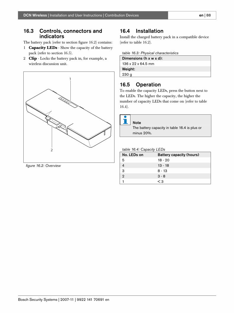
Bosch Security Systems | 2007-11 | 9922 141 70691 en
DCN Wireless | Installation and User Instructions | Contribution Devices en | 88
16.3 Controls, connectors and indicators
The battery pack (refer to section figure 16.2) contains:1 Capacity LEDs - Show the capacity of the battery
pack (refer to section 16.5).2 Clip - Locks the battery pack in, for example, a
wireless discussion unit.
16.4 InstallationInstall the charged battery pack in a compatible device (refer to table 16.2).
16.5 OperationTo enable the capacity LEDs, press the button next to the LEDs. The higher the capacity, the higher the number of capacity LEDs that come on (refer to table 16.4).
figure 16.2: Overview
1
2
table 16.3: Physical characteristicsDimensions (h x w x d):136 x 22 x 64.5 mmWeight:230 g
NoteThe battery capacity in table 16.4 is plus or minus 20%.
table 16.4: Capacity LEDsNo. LEDs on Battery capacity (hours)5 18 - 204 13 - 183 8 - 13 2 3 - 8 1 < 3
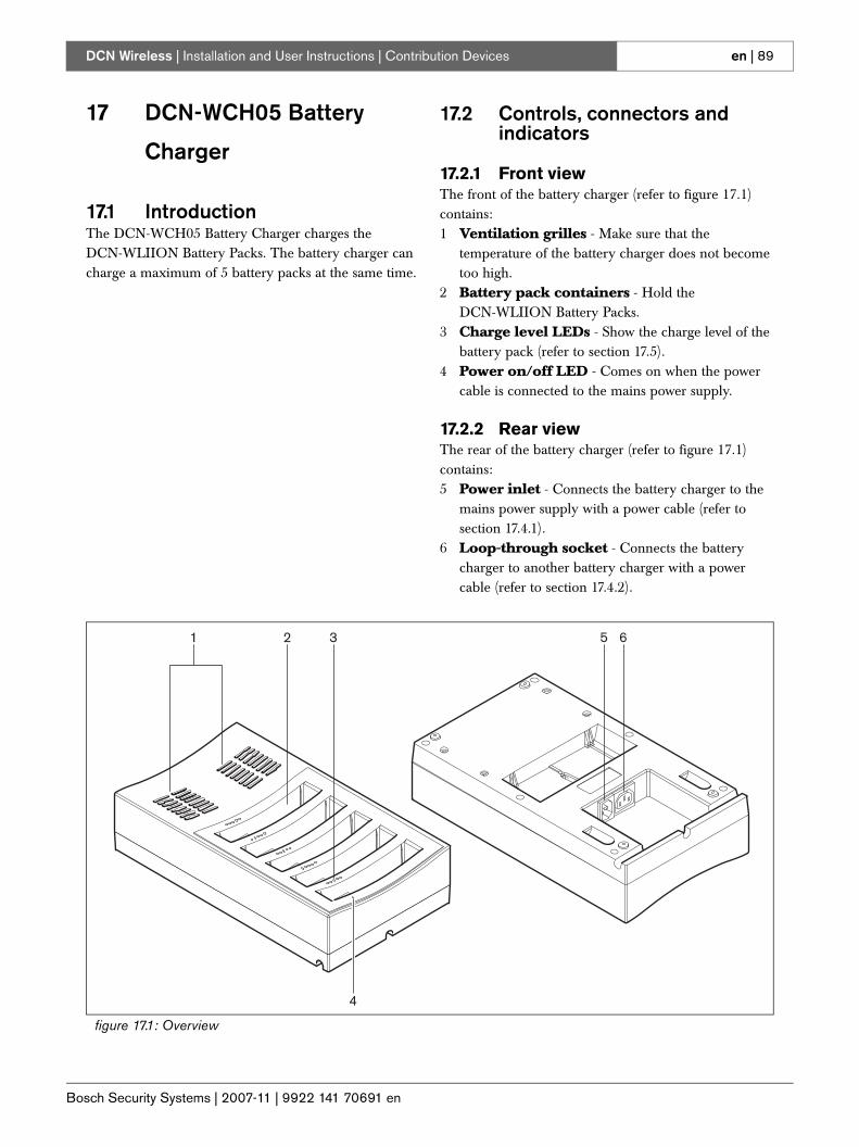
Bosch Security Systems | 2007-11 | 9922 141 70691 en
DCN Wireless | Installation and User Instructions | Contribution Devices en | 89
17 DCN-WCH05 Battery
Charger
17.1 IntroductionThe DCN-WCH05 Battery Charger charges the DCN-WLIION Battery Packs. The battery charger can charge a maximum of 5 battery packs at the same time.
17.2 Controls, connectors and indicators
17.2.1 Front viewThe front of the battery charger (refer to figure 17.1) contains:1 Ventilation grilles - Make sure that the
temperature of the battery charger does not become too high.
2 Battery pack containers - Hold the DCN-WLIION Battery Packs.
3 Charge level LEDs - Show the charge level of the battery pack (refer to section 17.5).
4 Power on/off LED - Comes on when the power cable is connected to the mains power supply.
17.2.2 Rear viewThe rear of the battery charger (refer to figure 17.1) contains:5 Power inlet - Connects the battery charger to the
mains power supply with a power cable (refer to section 17.4.1).
6 Loop-through socket - Connects the battery charger to another battery charger with a power cable (refer to section 17.4.2).
figure 17.1: Overview
4
1 2 3 5 6
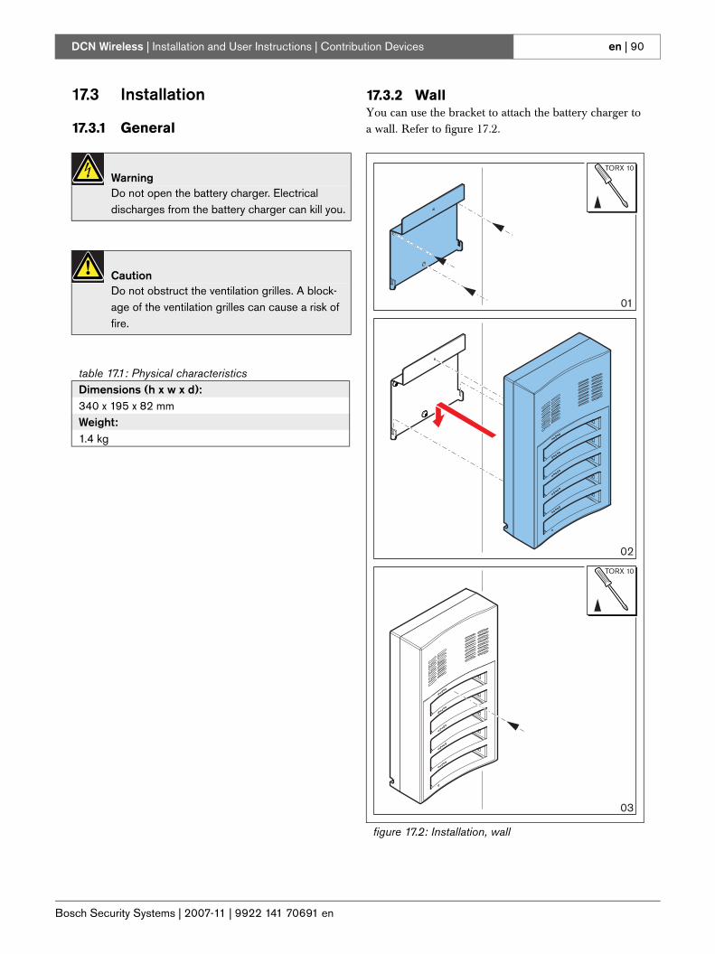
Bosch Security Systems | 2007-11 | 9922 141 70691 en
DCN Wireless | Installation and User Instructions | Contribution Devices en | 90
17.3 Installation
17.3.1 General
17.3.2 WallYou can use the bracket to attach the battery charger to a wall. Refer to figure 17.2.
WarningDo not open the battery charger. Electrical discharges from the battery charger can kill you.
CautionDo not obstruct the ventilation grilles. A block-age of the ventilation grilles can cause a risk of fire.
table 17.1: Physical characteristicsDimensions (h x w x d):340 x 195 x 82 mmWeight:1.4 kg
figure 17.2: Installation, wall
02
03
01
TORX 10
TORX 10
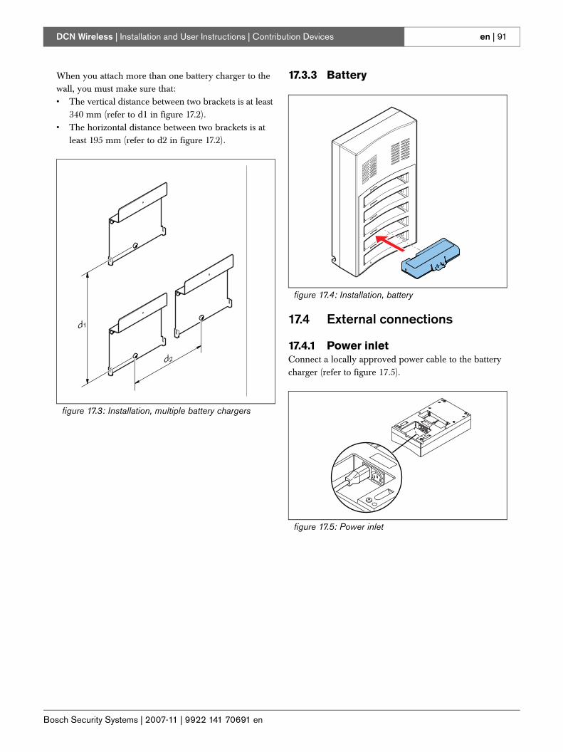
Bosch Security Systems | 2007-11 | 9922 141 70691 en
DCN Wireless | Installation and User Instructions | Contribution Devices en | 91
When you attach more than one battery charger to the wall, you must make sure that:• The vertical distance between two brackets is at least
340 mm (refer to d1 in figure 17.2).• The horizontal distance between two brackets is at
least 195 mm (refer to d2 in figure 17.2).
17.3.3 Battery
17.4 External connections
17.4.1 Power inletConnect a locally approved power cable to the battery charger (refer to figure 17.5).
figure 17.3: Installation, multiple battery chargers
d2
d1
figure 17.4: Installation, battery
figure 17.5: Power inlet
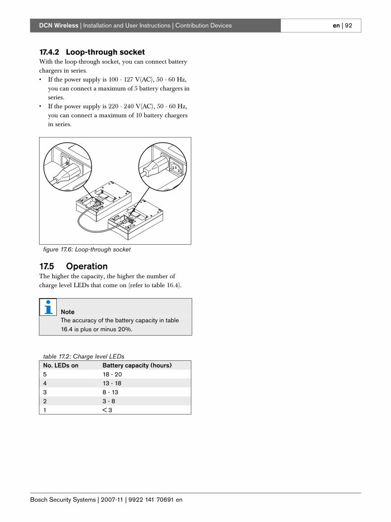
Bosch Security Systems | 2007-11 | 9922 141 70691 en
DCN Wireless | Installation and User Instructions | Contribution Devices en | 92
17.4.2 Loop-through socketWith the loop-through socket, you can connect battery chargers in series.• If the power supply is 100 - 127 V(AC), 50 - 60 Hz,
you can connect a maximum of 5 battery chargers in series.
• If the power supply is 220 - 240 V(AC), 50 - 60 Hz, you can connect a maximum of 10 battery chargers in series.
17.5 OperationThe higher the capacity, the higher the number of charge level LEDs that come on (refer to table 16.4).
figure 17.6: Loop-through socket
NoteThe accuracy of the battery capacity in table 16.4 is plus or minus 20%.
table 17.2: Charge level LEDsNo. LEDs on Battery capacity (hours)5 18 - 204 13 - 183 8 - 13 2 3 - 8 1 < 3
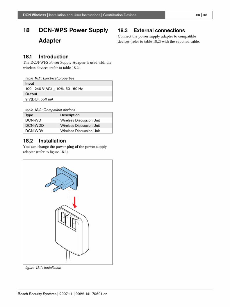
Bosch Security Systems | 2007-11 | 9922 141 70691 en
DCN Wireless | Installation and User Instructions | Contribution Devices en | 93
18 DCN-WPS Power Supply
Adapter
18.1 IntroductionThe DCN-WPS Power Supply Adapter is used with the wireless devices (refer to table 18.2).
18.2 InstallationYou can change the power plug of the power supply adapter (refer to figure 18.1).
18.3 External connectionsConnect the power supply adapter to compatible devices (refer to table 18.2) with the supplied cable.
table 18.1: Electrical propertiesInput100 - 240 V(AC) + 10%, 50 - 60 HzOutput9 V(DC), 550 mA
table 18.2: Compatible devicesType DescriptionDCN-WD Wireless Discussion UnitDCN-WDD Wireless Discussion UnitDCN-WDV Wireless Discussion Unit
figure 18.1: Installation
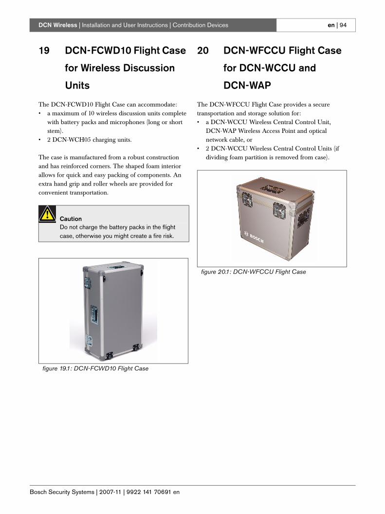
Bosch Security Systems | 2007-11 | 9922 141 70691 en
DCN Wireless | Installation and User Instructions | Contribution Devices en | 94
19 DCN-FCWD10 Flight Case
for Wireless Discussion
Units
The DCN-FCWD10 Flight Case can accommodate:• a maximum of 10 wireless discussion units complete
with battery packs and microphones (long or short stem).
• 2 DCN-WCH05 charging units.
The case is manufactured from a robust construction and has reinforced corners. The shaped foam interior allows for quick and easy packing of components. An extra hand grip and roller wheels are provided for convenient transportation.
20 DCN-WFCCU Flight Case
for DCN-WCCU and
DCN-WAP
The DCN-WFCCU Flight Case provides a secure transportation and storage solution for:• a DCN-WCCU Wireless Central Control Unit,
DCN-WAP Wireless Access Point and optical network cable, or
• 2 DCN-WCCU Wireless Central Control Units (if dividing foam partition is removed from case).
CautionDo not charge the battery packs in the flight case, otherwise you might create a fire risk.
figure 19.1: DCN-FCWD10 Flight Case
figure 20.1: DCN-WFCCU Flight Case
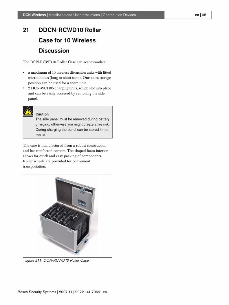
Bosch Security Systems | 2007-11 | 9922 141 70691 en
DCN Wireless | Installation and User Instructions | Contribution Devices en | 95
21 DDCN-RCWD10 Roller
Case for 10 Wireless
Discussion
The DCN-RCWD10 Roller Case can accommodate:
• a maximum of 10 wireless discussion units with fitted microphones (long or short stem). One extra storage position can be used for a spare unit.
• 2 DCN-WCH05 charging units, which slot into place and can be easily accessed by removing the side panel.
The case is manufactured from a robust construction and has reinforced corners. The shaped foam interior allows for quick and easy packing of components. Roller wheels are provided for convenient transportation.
CautionThe side panel must be removed during battery charging, otherwise you might create a fire risk. During charging the panel can be stored in the top lid.
figure 21.1: DCN-RCWD10 Roller Case

Bosch Security Systems | 2007-11 | 9922 141 70691 en
DCN Wireless | Installation and User Instructions | Contribution Devices en | 96
Intentionally left blank.
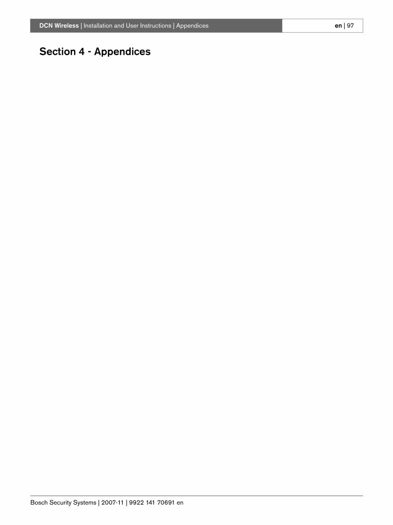
Bosch Security Systems | 2007-11 | 9922 141 70691 en
DCN Wireless | Installation and User Instructions | Appendices en | 97
Section 4 - Appendices
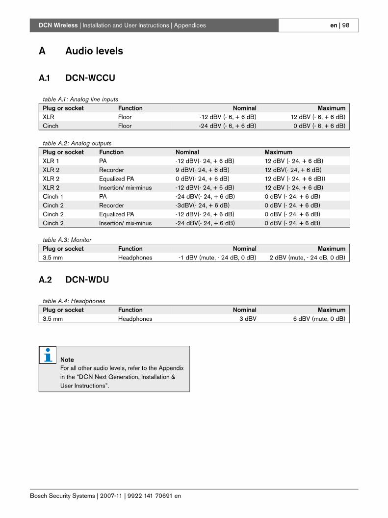
Bosch Security Systems | 2007-11 | 9922 141 70691 en
DCN Wireless | Installation and User Instructions | Appendices en | 98
A Audio levels
A.1 DCN-WCCU
A.2 DCN-WDU
table A.1: Analog line inputsPlug or socket Function Nominal MaximumXLR Floor -12 dBV (- 6, + 6 dB) 12 dBV (- 6, + 6 dB)Cinch Floor -24 dBV (- 6, + 6 dB) 0 dBV (- 6, + 6 dB)
table A.2: Analog outputsPlug or socket Function Nominal MaximumXLR 1 PA -12 dBV(- 24, + 6 dB) 12 dBV (- 24, + 6 dB)XLR 2 Recorder 9 dBV(- 24, + 6 dB) 12 dBV(- 24, + 6 dB)XLR 2 Equalized PA 0 dBV(- 24, + 6 dB) 12 dBV (- 24, + 6 dB))XLR 2 Insertion/ mix-minus -12 dBV(- 24, + 6 dB) 12 dBV (- 24, + 6 dB)Cinch 1 PA -24 dBV(- 24, + 6 dB) 0 dBV (- 24, + 6 dB)Cinch 2 Recorder -3dBV(- 24, + 6 dB) 0 dBV (- 24, + 6 dB)Cinch 2 Equalized PA -12 dBV(- 24, + 6 dB) 0 dBV (- 24, + 6 dB)Cinch 2 Insertion/ mix-minus -24 dBV(- 24, + 6 dB) 0 dBV (- 24, + 6 dB)
table A.3: MonitorPlug or socket Function Nominal Maximum3.5 mm Headphones -1 dBV (mute, - 24 dB, 0 dB) 2 dBV (mute, - 24 dB, 0 dB)
table A.4: HeadphonesPlug or socket Function Nominal Maximum3.5 mm Headphones 3 dBV 6 dBV (mute, 0 dB)
NoteFor all other audio levels, refer to the Appendix in the “DCN Next Generation, Installation & User Instructions”.
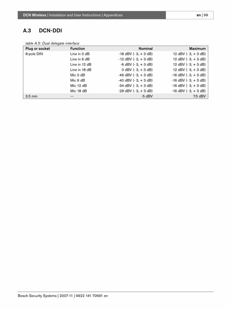
Bosch Security Systems | 2007-11 | 9922 141 70691 en
DCN Wireless | Installation and User Instructions | Appendices en | 99
A.3 DCN-DDI
table A.5: Dual delegate interfacePlug or socket Function Nominal Maximum8-pole DIN Line in 0 dB
Line in 6 dBLine in 12 dBLine in 18 dBMic 0 dBMic 6 dBMic 12 dBMic 18 dB
-18 dBV (- 3, + 3 dB)-12 dBV (- 3, + 3 dB)-6 dBV (- 3, + 3 dB)0 dBV (- 3, + 3 dB)
-46 dBV (- 3, + 3 dB)-40 dBV (- 3, + 3 dB)-34 dBV (- 3, + 3 dB)-28 dBV (- 3, + 3 dB)
12 dBV (- 3, + 3 dB)12 dBV (- 3, + 3 dB)12 dBV (- 3, + 3 dB)12 dBV (- 3, + 3 dB)
-16 dBV (- 3, + 3 dB)-16 dBV (- 3, + 3 dB)-16 dBV (- 3, + 3 dB)-16 dBV (- 3, + 3 dB)
3.5 mm --- -5 dBV 7.5 dBV
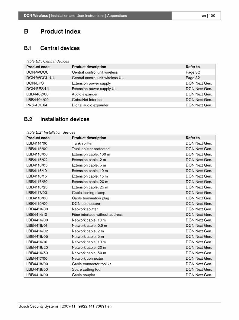
Bosch Security Systems | 2007-11 | 9922 141 70691 en
DCN Wireless | Installation and User Instructions | Appendices en | 100
B Product index
B.1 Central devices
B.2 Installation devices
table B.1: Central devicesProduct code Product description Refer toDCN-WCCU Central control unit wireless Page 32DCN-WCCU-UL Central control unit wireless UL Page 32DCN-EPS Extension power supply DCN Next Gen.DCN-EPS-UL Extension power supply UL DCN Next Gen.LBB4402/00 Audio expander DCN Next Gen.LBB4404/00 CobraNet Interface DCN Next Gen.PRS-4DEX4 Digital audio expander DCN Next Gen.
table B.2: Installation devicesProduct code Product description Refer toLBB4114/00 Trunk splitter DCN Next Gen.LBB4115/00 Trunk splitter protected DCN Next Gen.LBB4116/00 Extension cable, 100 m DCN Next Gen.LBB4116/02 Extension cable, 2 m DCN Next Gen.LBB4116/05 Extension cable, 5 m DCN Next Gen.LBB4116/10 Extension cable, 10 m DCN Next Gen.LBB4116/15 Extension cable, 15 m DCN Next Gen.LBB4116/20 Extension cable, 20 m DCN Next Gen.LBB4116/25 Extension cable, 25 m DCN Next Gen.LBB4117/00 Cable locking clamp DCN Next Gen.LBB4118/00 Cable termination plug DCN Next Gen.LBB4119/00 DCN connectors DCN Next Gen.LBB4410/00 Network splitter DCN Next Gen.LBB4414/10 Fiber interface without address DCN Next Gen.LBB4416/00 Network cable, 10 m DCN Next Gen.LBB4416/01 Network cable, 0.5 m DCN Next Gen.LBB4416/02 Network cable, 2 m DCN Next Gen.LBB4416/05 Network cable, 5 m DCN Next Gen.LBB4416/10 Network cable, 10 m DCN Next Gen.LBB4416/20 Network cable, 20 m DCN Next Gen.LBB4416/50 Network cable, 50 m DCN Next Gen.LBB4417/00 Network connector DCN Next Gen.LBB4418/00 Cable-connector tool kit DCN Next Gen.LBB4418/50 Spare cutting tool DCN Next Gen.LBB4419/00 Cable coupler DCN Next Gen.
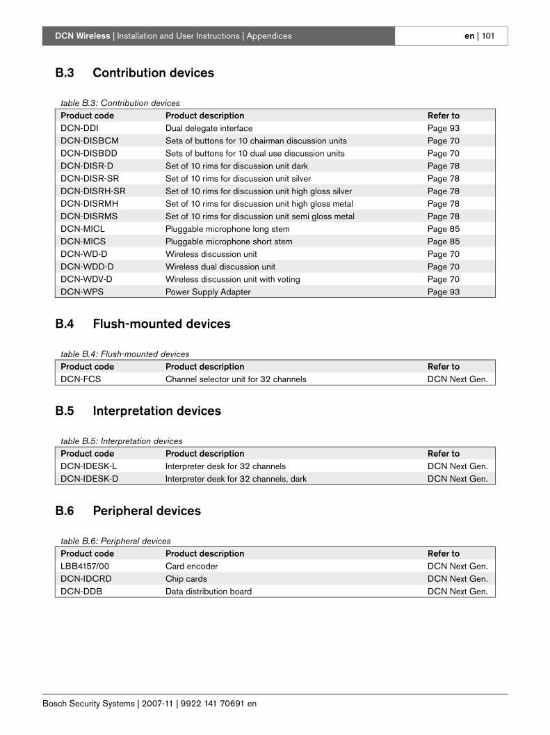
Bosch Security Systems | 2007-11 | 9922 141 70691 en
DCN Wireless | Installation and User Instructions | Appendices en | 101
B.3 Contribution devices
B.4 Flush-mounted devices
B.5 Interpretation devices
B.6 Peripheral devices
table B.3: Contribution devicesProduct code Product description Refer toDCN-DDI Dual delegate interface Page 93DCN-DISBCM Sets of buttons for 10 chairman discussion units Page 70DCN-DISBDD Sets of buttons for 10 dual use discussion units Page 70DCN-DISR-D Set of 10 rims for discussion unit dark Page 78DCN-DISR-SR Set of 10 rims for discussion unit silver Page 78DCN-DISRH-SR Set of 10 rims for discussion unit high gloss silver Page 78DCN-DISRMH Set of 10 rims for discussion unit high gloss metal Page 78DCN-DISRMS Set of 10 rims for discussion unit semi gloss metal Page 78DCN-MICL Pluggable microphone long stem Page 85DCN-MICS Pluggable microphone short stem Page 85DCN-WD-D Wireless discussion unit Page 70DCN-WDD-D Wireless dual discussion unit Page 70DCN-WDV-D Wireless discussion unit with voting Page 70DCN-WPS Power Supply Adapter Page 93
table B.4: Flush-mounted devicesProduct code Product description Refer toDCN-FCS Channel selector unit for 32 channels DCN Next Gen.
table B.5: Interpretation devicesProduct code Product description Refer toDCN-IDESK-L Interpreter desk for 32 channels DCN Next Gen.DCN-IDESK-D Interpreter desk for 32 channels, dark DCN Next Gen.
table B.6: Peripheral devicesProduct code Product description Refer toLBB4157/00 Card encoder DCN Next Gen.DCN-IDCRD Chip cards DCN Next Gen.DCN-DDB Data distribution board DCN Next Gen.
Bosch Security Systems | 2007-11 | 9922 141 70691 en
DCN Wireless | Installation and User Instructions | Appendices en | 102
C Statements for FCC &
Industry Canada
This Class B digital apparatus complies with Canadian ICES-003.Cet appareil numérique de la classe B est conforme à la norme NMB-003 du Canada.The DCN-Wireless equipment has been tested and found to comply with the limits for a Class B digital device, pursuant to Part 15 of the FCC Rules. These limits are designed to provide reasonable protection against harmful interference in a residential installation.This equipment generates, uses and can radiate radio frequency energy and, if not installed and used in accordance with the instructions, may cause harmful interference to radio communications. However, there is no guarantee that interference will not occur in a particular installation. If this equipment does cause harmful interference to radio or television reception, which can be determined by turning the equipment off and on, the user is encouraged to try to correct the interference by one or more of the followingmeasures:• Reorient or relocate the receiving antenna.• Increase the separation between the equipment and
receiver.• Connect the equipment into an outlet on a circuit
different from that to which the receiver is connected.
• Consult the dealer or an experienced radio/TV technician for help.
The Wireless Discussion Units and the Wireless Access Point comply with Part 15 of the FCC Rules and with RSS-210 of Industry Canada.Operation is subject to the following two conditions:(1) this device may not cause harmful interference, and(2) this device must accept any interference received,including interference that may cause undesired operation.
WarningChanges or modifications made to this equipment not expressly approved by Bosch Security Systems B.V. may void the FCC authorization to operate this equipment.
NoteThe Wireless Discussion Units and the Wireless Access Point comply with FCC radiation exposure limits set forth for an uncontrolled environment. The Wireless Discussion Units and the Wireless Access Point should be installed and operated with minimum distance of 20 cm to your body. The RF-parts of the Wireless Discussion Units and the Wireless Access Point must not be co-located or operating in conjunction with any other antenna or transmitter.
Bosch Security Systems | 2007-11 | 9922 141 70691 en
DCN Wireless | Installation and User Instructions | Appendices en | 103
D Declarations

Bosch Security Systems | 2007-11 | 9922 141 70691 en
DCN Wireless | Installation and User Instructions | Appendices en | 104
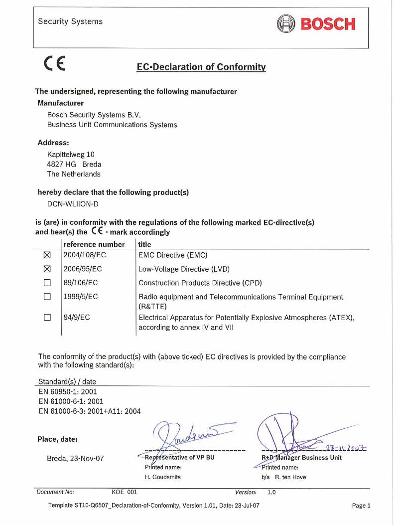
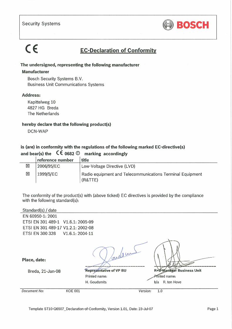

For more information visit
www.boschsecuritysystems.com
© Bosch Security Systems B.V.
Data subject to change without notice
2007-11 | 9922 141 70691 en


