40
ECE 546 – Jose Schutt‐Aine 1 Spring 2018 Jose E. Schutt-Aine Electrical & Computer Engineering University of Illinois [email protected] ECE 546 Lecture ‐ 23 Jitter Basics
ECE 546 – Jose Schutt‐Aine 1
Spring 2018
Jose E. Schutt-AineElectrical & Computer Engineering
University of [email protected]
ECE 546 Lecture ‐ 23Jitter Basics
ECE 546 – Jose Schutt‐Aine 2
Probe Further
• D. Derickson and M. Muller, “Digital Communications Test and Measurement”, Prentice Hall, 2007.
• Kyung Suk (Dan) Oh and Xingchao (Chuck) Yuan, High‐Speed Signaling: Jitter Modeling, Analysis, and Budgeting, Prentice Hall, 2012
• Mike Peng Li, Jitter, Noise and Signal Integrity at High‐Speed, Prentice Hall, 2008
ECE 546 – Jose Schutt‐Aine 3
• Timing uncertainties in digital transmission systems
• Utmost importance because timing uncertainties cause bit errors
• There are different types of jitter
Jitter Definition
Jitter is difference in time between when an eventwas ideally to occur and when it actually did occur.
ECE 546 – Jose Schutt‐Aine 4
• Jitter is a signal timing deviation referenced to a recovered clock from the recovered bit stream
• Measured in Unit Intervals and captured visually with eye diagrams
• Two types of jitter– Deterministic (non Gaussian)– Random
• The total jitter (TJ) is the sum of the random (RJ) and deterministic jitter(DJ)
Jitter Characteristics

ECE 546 – Jose Schutt‐Aine 5
Types of Jitter
•Deterministic Jitter (DDJ)Data‐Dependent Jitter (DDJ)Periodic Jitter (PJ)Bounded Uncorrelated Jitter (BUJ)
•Random Jitter (RJ)Gaussian JitterfHigher‐Order Jitter

Bandwidth LimitationsCause intersymbol interference (ISI) ISI occurs if time required by signal to completely
charge is longer than bit intervalAmount of ISI is function of channel and data
content of signal
Jitter Effects
Oscillator Phase NoisePresent in reference clocks or high-speed clocks In PLL based clocks, phase noise can be
amplified
ECE 546 – Jose Schutt‐Aine 7
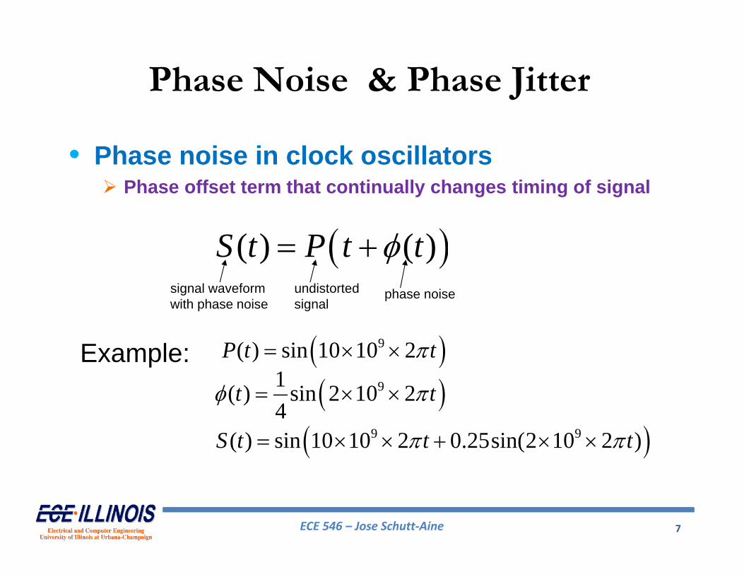
Phase Noise & Phase Jitter
• Phase noise in clock oscillators Phase offset term that continually changes timing of signal
( ) ( )S t P t t signal waveformwith phase noise
undistortedsignal
phase noise
Example: 9( ) sin 10 10 2P t t
91( ) sin 2 10 24
t t
9 9( ) sin 10 10 2 0.25sin(2 10 2 )S t t t

ECE 546 – Jose Schutt‐Aine 8
Phase Noise
clean signalnoisy signal
2 GHz phase noise

ECE 546 – Jose Schutt‐Aine 9
Phase Jitter
clean signalnoisy signal
ECE 546 – Jose Schutt‐Aine 10
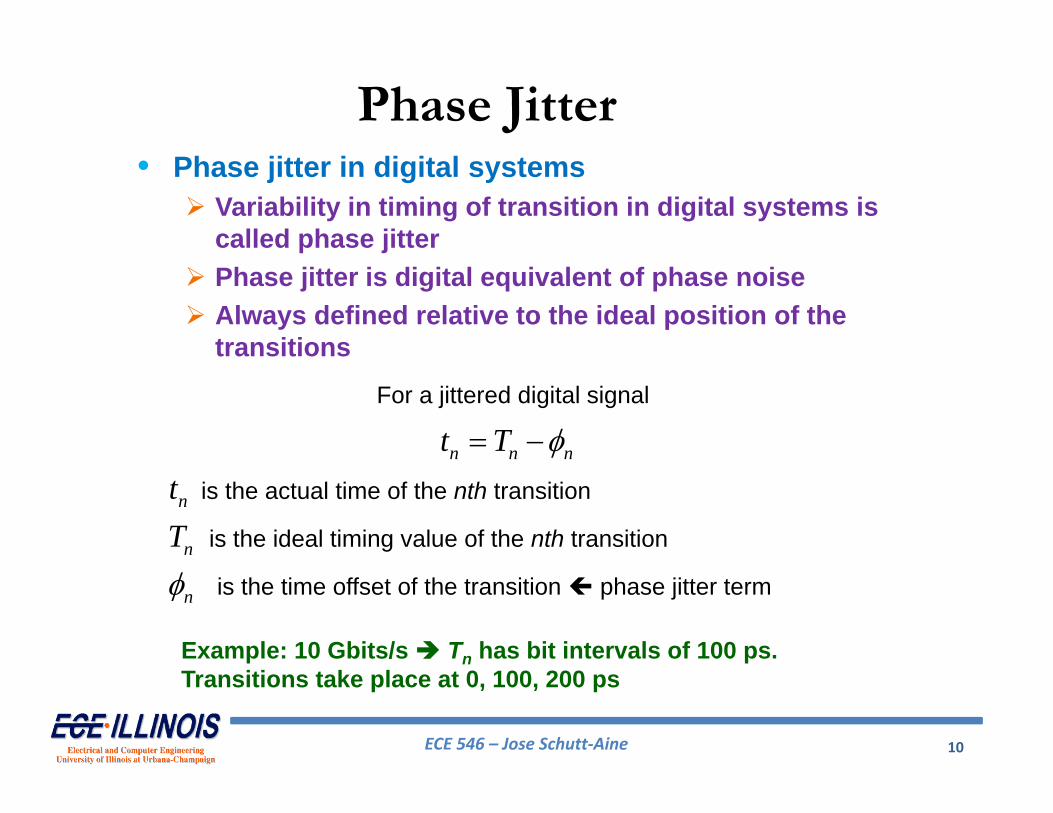
• Phase jitter in digital systems Variability in timing of transition in digital systems is
called phase jitter Phase jitter is digital equivalent of phase noise Always defined relative to the ideal position of the
transitions
Phase Jitter
n n nt T For a jittered digital signal
nt
nTis the actual time of the nth transition
nis the ideal timing value of the nth transition
is the time offset of the transition phase jitter term
Example: 10 Gbits/s Tn has bit intervals of 100 ps. Transitions take place at 0, 100, 200 ps
ECE 546 – Jose Schutt‐Aine 11
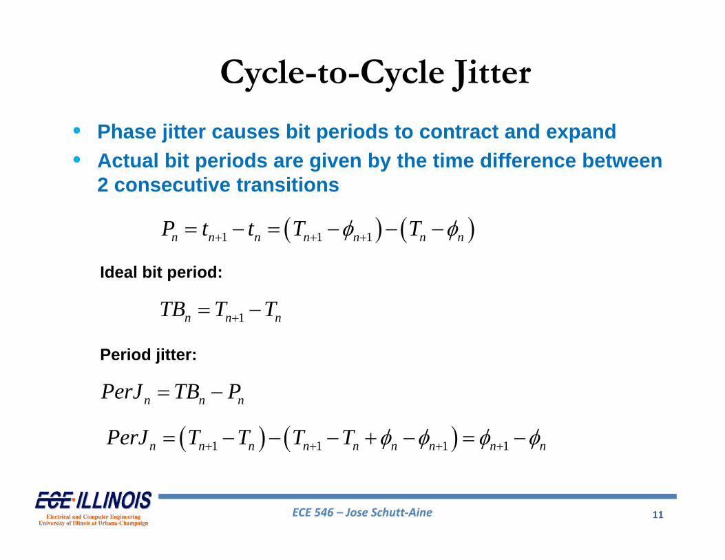
• Phase jitter causes bit periods to contract and expand• Actual bit periods are given by the time difference between
2 consecutive transitions
1 1 1n n n n n n nP t t T T
Ideal bit period:
1n n nTB T T
Period jitter:
n n nPerJ TB P
1 1 1 1n n n n n n n n nPerJ T T T T
Cycle-to-Cycle Jitter

ECE 546 – Jose Schutt‐Aine 12
Cycle-to-cycle jitter:
1n n nCCJit P P
1n n nCCJit PerJ PerJ
Cycle-to-Cycle Jitter
ECE 546 – Jose Schutt‐Aine 13
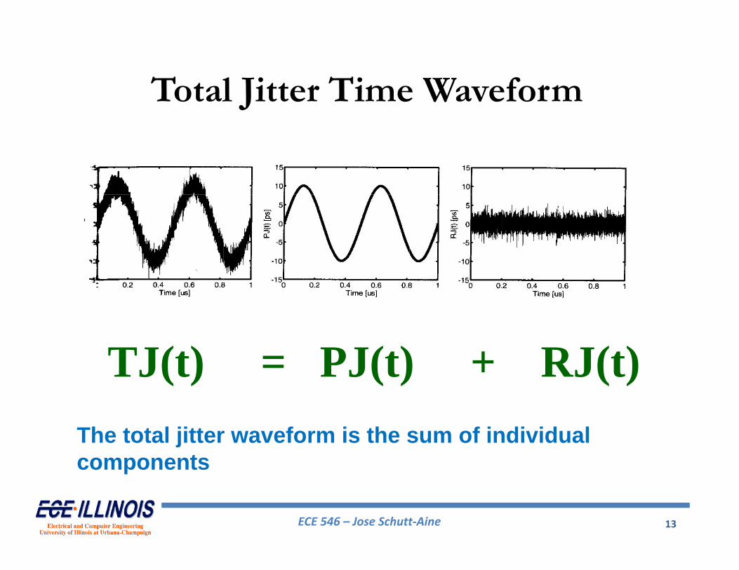
Total Jitter Time Waveform
The total jitter waveform is the sum of individual components
TJ(t) = PJ(t) + RJ(t)

ECE 546 – Jose Schutt‐Aine 14
Jitter StatisticsMost common way to look at jitter is in statistical domain
Because one can observe jitter histograms directly on oscilloscopes
No instruments to measure jitter time waveform or frequency spectrum directly
Jitter Histograms and Probability Density Functions Built directly from time waveforms Frequency information is lostPeak‐to‐peak value depends on observation time
Note: A jitter histogram does not contain all the information about the jitter
ECE 546 – Jose Schutt‐Aine 15
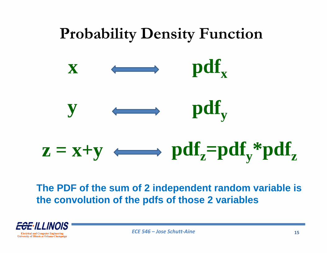
Probability Density Function
The PDF of the sum of 2 independent random variable is the convolution of the pdfs of those 2 variables
x
y
z = x+y
pdfx
pdfy
pdfz=pdfy*pdfz

ECE 546 – Jose Schutt‐Aine 16
Jitter Statistics
TJ(x) = PJ(x) * RJ(x)The total jitter PDF is the convolution of individual components

ECE 546 – Jose Schutt‐Aine 17
• Transfer of Level Noise into the Time DomainNoise on digital data signals causes jitter because it offsets the threshold crossing point in time
• Bandwidth LimitationsPrimarily caused by intersymbol interference
•Oscillator Phase NoisePhase noise present in reference clocks especially in systems based on PLL
Jitter Mechanisms
ECE 546 – Jose Schutt‐Aine 18
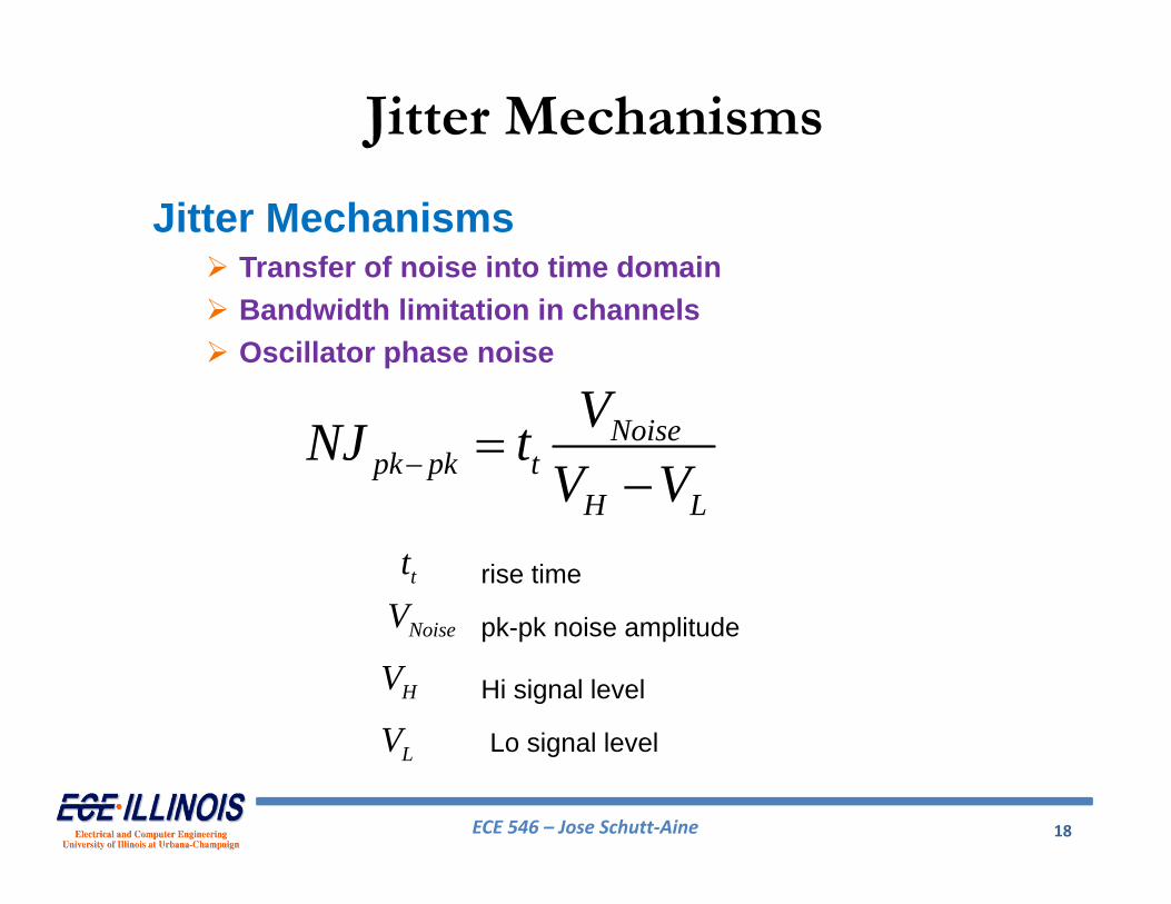
Jitter Mechanisms Transfer of noise into time domain Bandwidth limitation in channels Oscillator phase noise
Noisepk pk t
H L
VNJ tV V
NoiseVtt
HV
LV
rise time
pk-pk noise amplitude
Hi signal level
Lo signal level
Jitter Mechanisms

ECE 546 – Jose Schutt‐Aine 19
Jitter MechanismsLinear model
Random noise caused by thermal effects
Jitter ~ 2ps Jitter ~ 6ps
Noisepk pk t
H L
VNJ tV V
ECE 546 – Jose Schutt‐Aine 20
Jitter Mechanisms
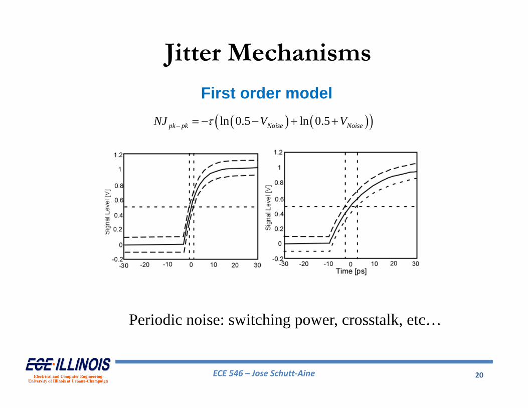
First order model
Periodic noise: switching power, crosstalk, etc…
ln 0.5 ln 0.5pk pk Noise NoiseNJ V V
ECE 546 – Jose Schutt‐Aine 21
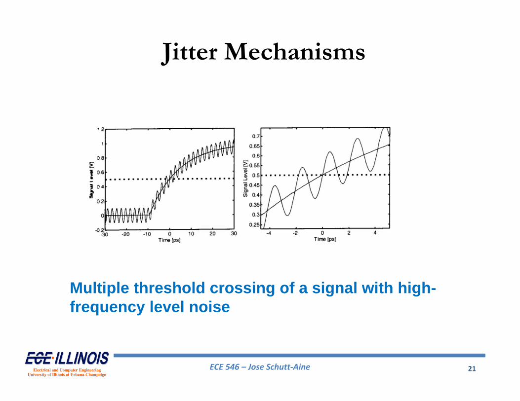
Jitter Mechanisms
Multiple threshold crossing of a signal with high-frequency level noise

ECE 546 – Jose Schutt‐Aine 22
Bandwidth Limitations
0001111 data pattern

ECE 546 – Jose Schutt‐Aine 23
0101111 data pattern
Bandwidth Limitations

ECE 546 – Jose Schutt‐Aine 24
Jitter Classification

ECE 546 – Jose Schutt‐Aine 25
Gaussian Random Jitter
• Random jitter can be described by a Gaussian distribution with the following probability density function
2221( )
2
x
RJPDF x e
x
: independent value
: RMS value
: mean of distribution (zero by definition)
Note: the PDF of a Gaussian process is unbounded, i.e, its PDF is not zero unless the jitter t approaches infinity
ECE 546 – Jose Schutt‐Aine 26
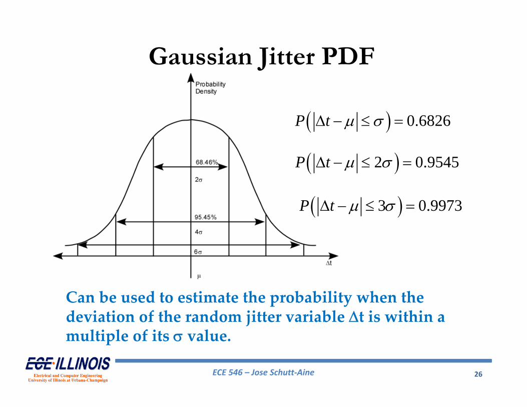
Gaussian Jitter PDF
Can be used to estimate the probability when the deviation of the random jitter variable t is within a multiple of its value.
0.6826P t
2 0.9545P t
3 0.9973P t

ECE 546 – Jose Schutt‐Aine 27
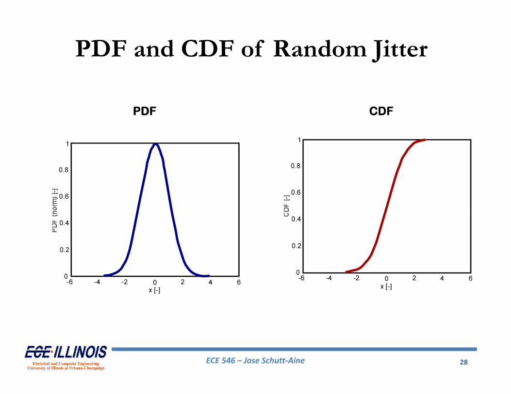
Cumulative Density Function
Cumulative density function (CDF) is defined as:
( ) ( )t
CDF t PDF x dx
CDF(t) tells us the probability that the transition occurred earlier than t. For random jitter, we get:
1 1( )2 2 2RJ
xCDF x erf
erf is the error function
ECE 546 – Jose Schutt‐Aine 28
PDF and CDF of Random Jitter
PDF CDF

ECE 546 – Jose Schutt‐Aine 29
• Crosstalk– Noisy neighboring signals
• Interference
• Reflections– Imperfect terminations– Discontinuities (e.g. multi-drop buses, stubs)
• Simultaneous switching noise (SSN)– Noisy reference plane or power rail– Shift in threshold voltages
Causes of Deterministic Jitter

ECE 546 – Jose Schutt‐Aine 30
Data-Dependent Jitter
• Most commonly encountered DJ type• Dominant limiting factor for link channels• Due to memory of lossy electrical or optical
system• Bit transition of current bit depends on the
transition times of the previous bits
ECE 546 – Jose Schutt‐Aine 31
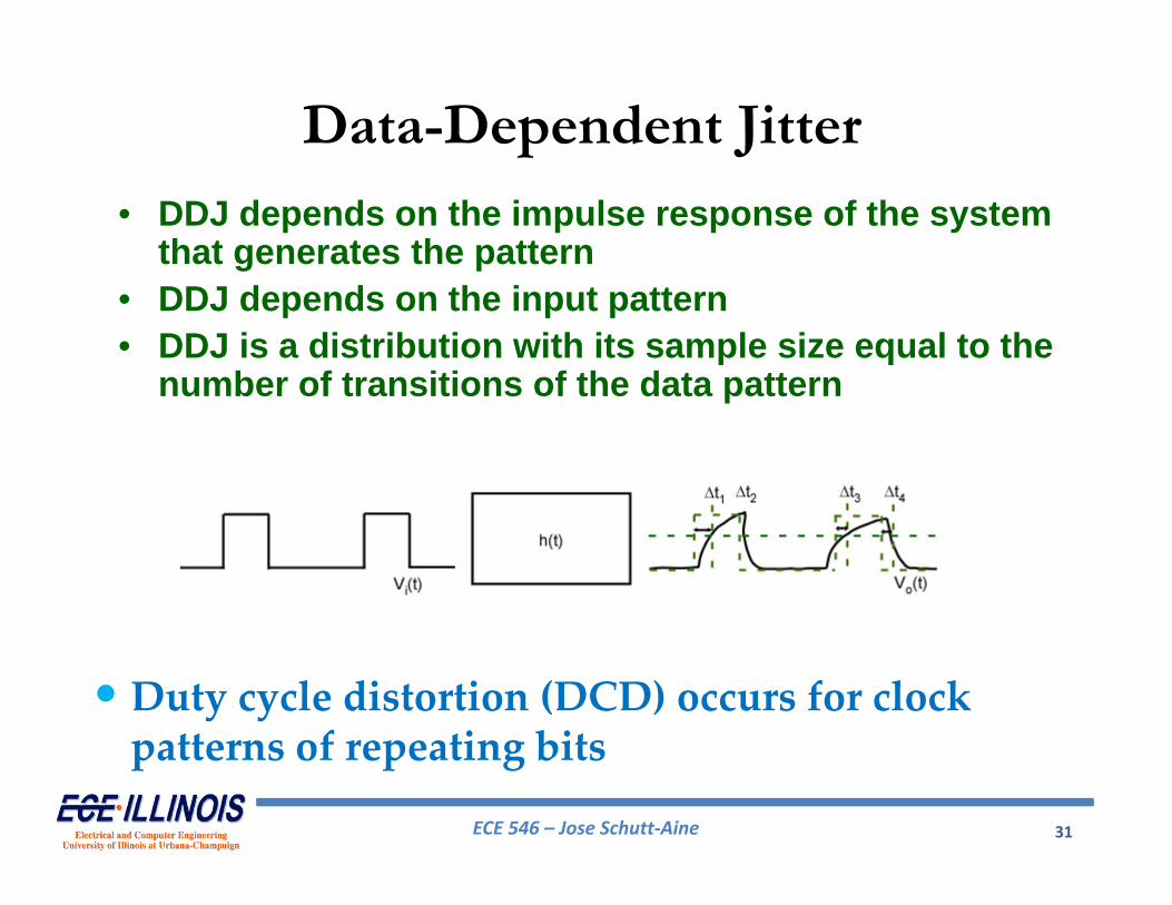
Data-Dependent Jitter
• DDJ depends on the impulse response of the system that generates the pattern
• DDJ depends on the input pattern• DDJ is a distribution with its sample size equal to the
number of transitions of the data pattern
•Duty cycle distortion (DCD) occurs for clock patterns of repeating bits

ECE 546 – Jose Schutt‐Aine 32
Data-Dependent Jitter
• Since channel does not have zero-rise time step response or infinite bandwidth, jitter is to be expected
• Settling time gives good indication of jitter

ECE 546 – Jose Schutt‐Aine 33
Model for DDJ
1
( )N
DDJ DDJDDJ i i
i
f t P t D
DDJiP is the probability for the DDJ value of DDJ
iD
The generic form for DDJ PDF is:
DDJiP
1
1N
DDJi
i
P
satisfies the condition

ECE 546 – Jose Schutt‐Aine 34
Periodic JitterPeriodic jitter is a repeating jitter signal at a certain period or frequency. It is described by:
cos ot A t
2
1 ,1 /
PJf t A t At A
The PDF for the single PJ is given by
Which can be approximated by
12PJf t t A t A
o: angular frequency: initial phase

ECE 546 – Jose Schutt‐Aine 35
Periodic Jitter
PDF for single sinusoidal
2
1 ,1 /
PJf t A t At A

ECE 546 – Jose Schutt‐Aine 36
Periodic Jitter
There are 3 common waveforms for the theoretical analysis of periodic jitter
1 1( )2 2 2 2PJ rect
m mPDF x
Rectangle Periodic Jitter
1( ) 2
0PJ triang
mfor xPDF x m
otherwise
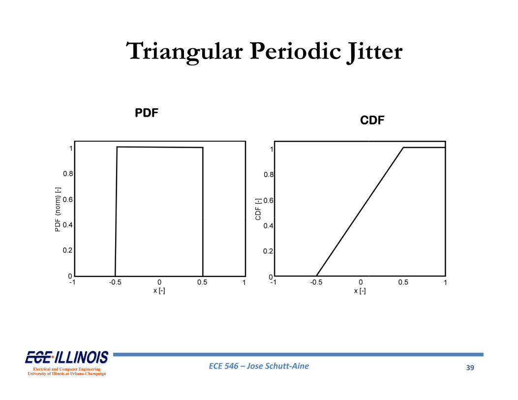
Triangle Periodic Jitter
ECE 546 – Jose Schutt‐Aine 37
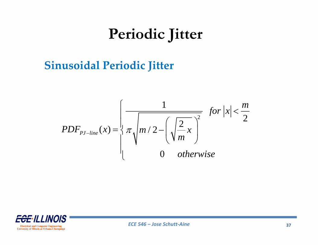
Periodic Jitter
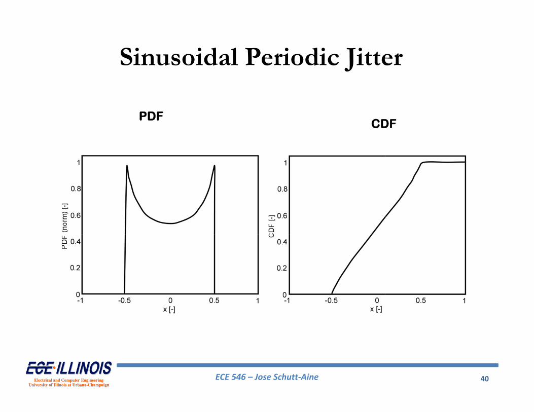
2
122( ) / 2
0
PJ line
mfor x
PDF x m xm
otherwise
Sinusoidal Periodic Jitter

ECE 546 – Jose Schutt‐Aine 38
Rectangular Periodic Jitter
PDFCDF
ECE 546 – Jose Schutt‐Aine 39
Triangular Periodic Jitter
PDFCDF
ECE 546 – Jose Schutt‐Aine 40
Sinusoidal Periodic Jitter
PDFCDF


