Electrode Boundary Layers in Direct-Current Plasma Accelerators 1 JACK L. KERREBROCK* California Institute of Technology Summary One of the problems that must be faced in the development of direct-current plasma accelerators is that of boundary-layer growth on the electrode surfaces. These surfaces must be main- tained at a somewhat lower temperature than is desirable in the bulk of the gas flow. The associated reduction in electrical con- ductivity near the electrode surface, together with the continuous current through the boundary layer, may result in greatly aug- mented Joule heating near the surface, and increased heat transfer. This phenomenon is treated within the framework of boundary- layer theory. It is found that similar solutions for the thermal and viscous boundary layers exist for a certain class of accelerated flows in which the velocity varies as a power of the streamwise coordinate. The solutions show that the heat-transfer rate at Mach numbers near unity may be as much as ten times that which would be expected for a normal boundary layer. At higher Mach numbers, the similarity is not precisely valid; however, the analysis indicates qualitative^ that a stagnation enthalpy overshoot may occur in the high-temperature portion of the boundary layer as a result of the electromagnetic accelera- tion. Introduction M ANY OF THE DEVICES which have been suggested for the electromagnetic acceleration of ionized gases for propulsive and other purposes require the presence of electrodes in contact with the flowing plasma. In such devices there may exist a type of boundary-layer flow in which there is an electric cur- rent normal to the wall and a magnetic field parallel to the wall and normal to the current. In order that it be a satisfactory conductor, the gas must be at a rather high temperature—at least 2,000°K—and if an appreciable current is to pass from the electrode to the gas, there must be intimate contact of the two. Thus a severe heat-transfer problem seems likely to arise. As will be demonstrated, the effect of the electrical interaction with the fluid, particularly the current flow normal to the wall, is to compound this heating prob- lem, which would be severe even for a normal boundary layer. Received April 20, 1960. f This research was supported by the United States Air Force through the Air Force Office of Scientific Research of the Air Research and Development Command, under Contract No. AF 49(638)-758. * Senior Research Fellow, Daniel and Florence Guggenheim Jet Propulsion Center. The author wishes to express his gratitude to Prof. Frank E. Marble who, through many discussions, contributed a great deal to the formulation and interpretation of this work. The current and magnetic field influence the bound- ary layer in three ways. Joule heating acts as a heat source. Energy is transported by the electron current. The crossed current and magnetic field yield a body force which, like that resulting from a longitudinal pressure gradient, is a constant per unit volume. Of these three effects, the Joule heating is the most un- usual. The heating rate varies inversely as the electri- cal conductivity, which in turn may be a strong function of the temperature. Near the electrode surface, where the temperature must be somewhat below that of the gas in the free stream, the conductivity is low, and the Joule-heating rate correspondingly high. The in- creased heating rate near the wall will lead to a higher temperature gradient at the wall, and increased heat transfer for a given wall temperature. The objective of the present work is to explore this situation within the framework of boundary-layer the- ory, with the particular goal of estimating the magni- tude of the heat transfer to be expected. Certain limitations of applicability arise from the nature of the boundary-layer theory itself, others from specific as- sumptions. In the first category, the continuum ap- proximation requires that the mean free path of the electrons be small compared to the boundary-layer thickness, hence that the pressure be high—a require- ment which will be stated more precisely later. It is also necessary that the free-stream and boundary- layer flows be separable—i.e., that the former be in- fluenced to only a small extent by the latter. T h e fluid mechanical implications of this requirement are well known. Electrically, it implies that the current normal to the wall be determined by the free-stream flow, hence that the resistance of the boundary layer be small compared to that of the free stream. The adoption of a model requiring these conditions for its validity is not meant to imply that they are the best operating conditions for a plasma accelerator; certainly it is not possible to define such conditions at the present time. The intent is rather to study some of the problems which are likely to occur for one possible choice of operating conditions. As to specific assumptions, the most important ones concern the magnitude and behavior of the conductiv- ity. It is assumed that the plasma is in thermal equilibrium at the local temperature and pressure. In view of the requirement for good electrical conductivity at as low a temperature as possible, ''seeding" with an alkali metal is postulated; further, 631 Downloaded by UNIVERSITY OF CALIFORNIA - DAVIS on February 1, 2015 | http://arc.aiaa.org | DOI: 10.2514/8.9117
Transcript
Electrode Boundary Layers in Direct-Current Plasma Accelerators1
JACK L. KERREBROCK*
California Institute of Technology
Summary
One of the problems that must be faced in the development of direct-current plasma accelerators is that of boundary-layer growth on the electrode surfaces. These surfaces must be maintained at a somewhat lower temperature than is desirable in the bulk of the gas flow. The associated reduction in electrical conductivity near the electrode surface, together with the continuous current through the boundary layer, may result in greatly augmented Joule heating near the surface, and increased heat transfer.
This phenomenon is treated within the framework of boundary-layer theory. I t is found that similar solutions for the thermal and viscous boundary layers exist for a certain class of accelerated flows in which the velocity varies as a power of the streamwise coordinate. The solutions show that the heat-transfer rate at Mach numbers near unity may be as much as ten times that which would be expected for a normal boundary layer.
At higher Mach numbers, the similarity is not precisely valid; however, the analysis indicates qual i tat ive^ that a stagnation enthalpy overshoot may occur in the high-temperature portion of the boundary layer as a result of the electromagnetic acceleration.
Introduction
MANY OF THE DEVICES which have been suggested for the electromagnetic acceleration of ionized
gases for propulsive and other purposes require the presence of electrodes in contact with the flowing plasma. In such devices there may exist a type of boundary-layer flow in which there is an electric current normal to the wall and a magnetic field parallel to the wall and normal to the current. In order tha t it be a satisfactory conductor, the gas must be a t a ra ther high temperature—at least 2,000°K—and if an appreciable current is to pass from the electrode to the gas, there must be int imate contact of the two. Thus a severe heat-transfer problem seems likely to arise. As will be demonstrated, the effect of the electrical interaction with the fluid, particularly the current flow normal to the wall, is to compound this heating problem, which would be severe even for a normal boundary layer.
Received April 20, 1960. f This research was supported by the United States Air Force
through the Air Force Office of Scientific Research of the Air Research and Development Command, under Contract No. AF 49(638)-758.
* Senior Research Fellow, Daniel and Florence Guggenheim Jet Propulsion Center.
The author wishes to express his gratitude to Prof. Frank E. Marble who, through many discussions, contributed a great deal to the formulation and interpretation of this work.
The current and magnetic field influence the boundary layer in three ways. Joule heating acts as a heat source. Energy is transported by the electron current. The crossed current and magnetic field yield a body force which, like tha t resulting from a longitudinal pressure gradient, is a constant per unit volume. Of these three effects, the Joule heating is the most unusual. The heating rate varies inversely as the electrical conductivity, which in turn may be a strong function of the temperature. Near the electrode surface, where the temperature must be somewhat below tha t of the gas in the free stream, the conductivity is low, and the Joule-heating rate correspondingly high. The increased heating ra te near the wall will lead to a higher temperature gradient a t the wall, and increased heat transfer for a given wall temperature.
The objective of the present work is to explore this situation within the framework of boundary-layer theory, with the particular goal of estimating the magnitude of the heat transfer to be expected. Certain limitations of applicability arise from the nature of the boundary-layer theory itself, others from specific assumptions. In the first category, the continuum approximation requires tha t the mean free pa th of the electrons be small compared to the boundary-layer thickness, hence tha t the pressure be high—a requirement which will be stated more precisely later. I t is also necessary tha t the free-stream and boundary-layer flows be separable—i.e., t ha t the former be influenced to only a small extent by the latter. The fluid mechanical implications of this requirement are well known. Electrically, it implies tha t the current normal to the wall be determined by the free-stream flow, hence tha t the resistance of the boundary layer be small compared to tha t of the free stream. The adoption of a model requiring these conditions for its validity is not meant to imply tha t they are the best operating conditions for a plasma accelerator; certainly it is not possible to define such conditions at the present time. The intent is rather to s tudy some of the problems which are likely to occur for one possible choice of operating conditions.
As to specific assumptions, the most important ones
concern the magnitude and behavior of the conductiv
ity. I t is assumed tha t the plasma is in thermal
equilibrium at the local temperature and pressure.
In view of the requirement for good electrical
conductivity a t as low a temperature as possible,
' 'seeding" with an alkali metal is postulated; further,
631
Dow
nloa
ded
by U
NIV
ER
SIT
Y O
F C
AL
IFO
RN
IA -
DA
VIS
on
Febr
uary
1, 2
015
| http
://ar
c.ai
aa.o
rg |
DO
I: 1
0.25
14/8
.911
7
632 J O U R N A L O F T H E A E R O S P A C E S C I E N C E S — A U G U S T 1 9 6 1
T, °K
^ \
\X)C
\ \ m
\/° \ / o
/ «» 0
ii a ml
"J f , - i / __
N ^ 1
\ \ \
V II o 7'l "I
3/
p , a t m
10
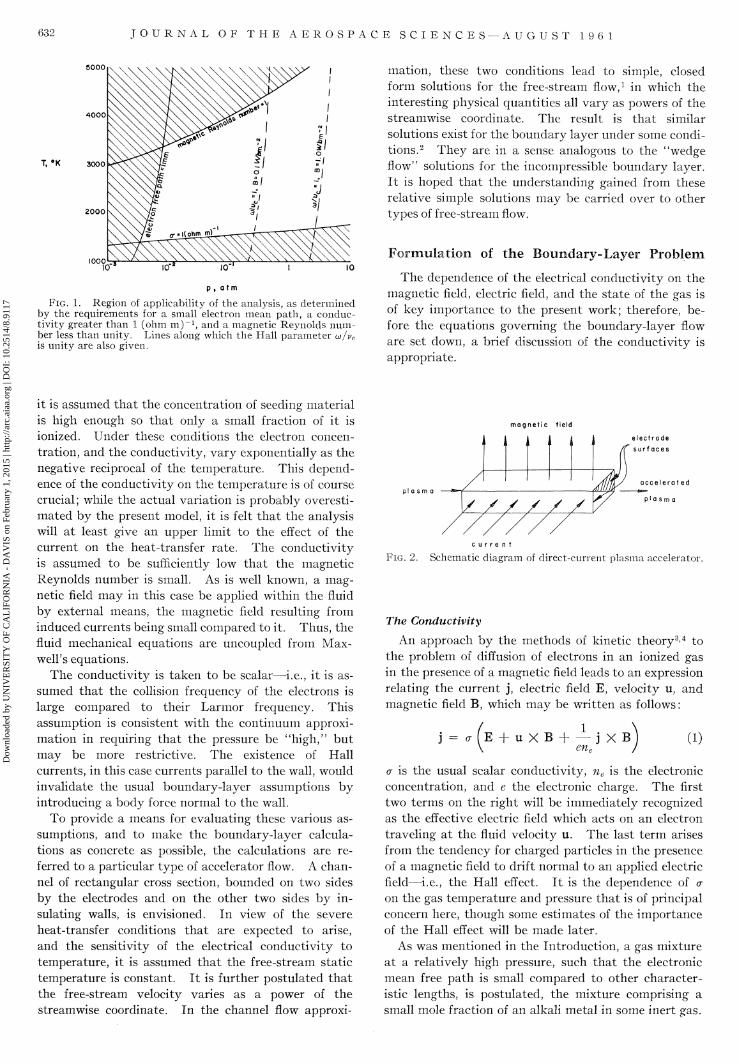
FIG. 1. Region of applicability of the analysis, as determined by the requirements for a small electron mean path, a conductivity greater than 1 (ohm m ) _ 1 , and a magnetic Reynolds number less than unity. Lines along which the Hall parameter GJ/VC is unity are also given.
mation, these two conditions lead to simple, closed form solutions for the free-stream flow,1 in which the interesting physical quantities all vary as powers of the streamwise coordinate. The result is t ha t similar solutions exist for the boundary layer under some conditions.2 They are in a sense analogous to the "wedge flow" solutions for the incompressible boundary layer. I t is hoped tha t the understanding gained from these relative simple solutions may be carried over to other types of free-stream flow.
F o r m u l a t i o n of t h e B o u n d a r y - L a y e r P r o b l e m
The dependence of the electrical conductivity on the magnetic field, electric field, and the s tate of the gas is of key importance to the present work; therefore, before the equations governing the boundary-layer flow are set down, a brief discussion of the conductivity is appropriate.
it is assumed tha t the concentration of seeding material is high enough so tha t only a small fraction of it is ionized. Under these conditions the electron concentration, and the conductivity, vary exponentially as the negative reciprocal of the temperature. This dependence of the conductivity on the temperature is of course crucial; while the actual variation is probably overestimated by the present model, it is felt t ha t the analysis will a t least give an upper limit to the effect of the current on the heat-transfer rate. The conductivity is assumed to be sufficiently low tha t the magnetic Reynolds number is small. As is well known, a magnetic field may in this case be applied within the fluid by external means, the magnetic field resulting from induced currents being small compared to it. Thus, the fluid mechanical equations are uncoupled from Maxwell's equations.
The conductivity is taken to be scalar—i.e., it is assumed t ha t the collision frequency of the electrons is large compared to their Larmor frequency. This assumption is consistent with the continuum approximation in requiring tha t the pressure be "high," but may be more restrictive. The existence of Hall currents, in this case currents parallel to the wall, would invalidate the usual boundary-layer assumptions by introducing a body force normal to the wall.
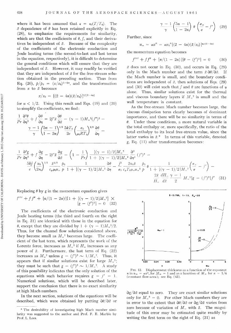
To provide a means for evaluating these various assumptions, and to make the boundary-layer calculations as concrete as possible, the calculations are referred to a particular type of accelerator flow. A channel of rectangular cross section, bounded on two sides by the electrodes and on the other two sides by insulating walls, is envisioned. In view of the severe heat-transfer conditions tha t are expected to arise, and the sensitivity of the electrical conductivity to temperature, it is assumed tha t the free-stream static temperature is constant. I t is further postulated tha t the free-stream velocity varies as a power of the streamwise coordinate. In the channel flow approxi-
m a g n e t i c f ie ld
,
^/^
. • 1 i 1
1/ / / / / /
t
4 sy
a c c e l e r a t ed
p ' as r r
c u r r e n t
FIG. 2. Schematic diagram of direct-current plasma accelerator.
The Conductivity
An approach by the methods of kinetic theory3-4 to the problem of diffusion of electrons in an ionized gas in the presence of a magnetic field leads to an expression relating the current j , electric field E, velocity u, and magnetic field B, which may be written as follows:
1 j = o - E + u X B H j X B (1)
a is the usual scalar conductivity, ne is the electronic concentration, and e the electronic charge. The first two terms on the right will be immediately recognized as the effective electric field which acts on an electron traveling at the fluid velocity u. The last term arises from the tendency for charged particles in the presence of a magnetic field to drift normal to an applied electric field—i.e., the Hall effect. I t is the dependence of a on the gas temperature and pressure t ha t is of principal concern here, though some estimates of the importance of the Hall effect will be made later.
As was mentioned in the Introduction, a gas mixture at a relatively high pressure, such tha t the electronic mean free pa th is small compared to other characteristic lengths, is postulated, the mixture comprising a small mole fraction of an alkali metal in some inert gas.
Dow
nloa
ded
by U
NIV
ER
SIT
Y O
F C
AL
IFO
RN
IA -
DA
VIS
on
Febr
uary
1, 2
015
| http
://ar
c.ai
aa.o
rg |
DO
I: 1
0.25
14/8
.911
7
D I R E C T - C U R R E N T P L A S M A A C C E L E R A T O R S 633
Under such conditions it is consistent to assume tha t the electrons diffuse under the influence of the electric field, with a velocity which is related to the electric field strength by a proportionality constant, /JL, called the mobility. Since the current is the product of the drift velocity, charge, and concentration of the electrons, the conductivity becomes a = \iene.
According to simple mean free pa th arguments, /JL is related to the collision frequency, vc, by /JL = e/mevc.
b
If the collision cross section is constant in electron energy, as it is for helium and hydrogen at low electron energies,5 then vc is directly proportional to the gas density and the electronic thermal speed. Thus if the electrons are in equilibrium with the gas, we may write
M/MO = (po/p)(T/T0yi*
where the subscript 0 denotes some reference condition. If the electrons are in equilibrium with the gas, their concentration is given by the Saha equation:
ne = [(2ww^r)8 / 2 /A8]1 / 2(« f l - ne)l/2e~I/2kT
where na is the total concentration of the ionizable species, / is the ionization potential, k is Boltzmann's constant, and h is Planck's constant. The fraction rte/na of the seeding material which is ionized thus satisfies an equation of the form
injnay = [1 - {ne/na)][p{T)/na]
For ne/na < 1, njna « f(T)/na1/2, while for f(T)/na »
1, njna « 1. Thus, njna is in general a rather complicated function of T.
I t is readily verified tha t for a given value of T, ne, and hence a, increases continuously as na increases, to t ha t in view of the probable severity of the heat-transfer problem, and the resulting desirability of obtaining the necessary gas conductivity a t as low a temperature as possible, i t will be assumed t ha t ne/na <C 1. I t should be noted tha t this assumption results in the greatest possible sensitivity of a to the temperature.
8=0.1766, X = 7.5, Moo= I, # w =0.5
V 2
e FIG. 3. Dimensionless temperature, 9 = T/Tco; profiles for
Mm = 1 and several values of the exponent, n in um = a X n\ dd/dx = 0.
8 * 0 . 1 7 6 6 , X = 7 .5 ,
de dx
Moo- 1, 0W = 0.5
• • 0 1
n J
0.21 I
0.25 ^ \ III 0,29 \ \ Svl 0.31 \ \ ^ N / / /
0.2 0.4 0.6 0.8 1.0
FIG. 4. Dimensionless velocity,/ ' = u/um: profiles for M<x>; = 1 and several values of the exponent n in iim = ax'1; dd/dx = 0.
The resulting expression for the conductivity, again referred to a reference condition, is
njn po
,[(na/n)0 p J 513/4 e - M ( i / * ) - i ]
where X = I/2kT0 and 6 = T/T0. In the present work it will be assumed tha t the mole fraction of ionizable gas, na/n, is constant throughout the flow field, so t ha t the final expression for the scalar conductivity is
(x/cro == (po/py/26^e - X [ ( l / 0 ) - l ] (2)
"uf The importance of the Hall effect can perhaps best be seen by rewriting Eq. (1) for the case in which there is bu t one component of B, say Bz, and the current is in the x, y plane. In terms of components i t then becomes
Jx a[Ex
f - ( c o A c ) i y ]
i + {u/vcy Jv i + (co/vcy
where a> = eBz/me is the Larmor frequency of the electrons, Ex
f "= Ex + vBz, and Ev' ~ Ey — uBz. If there is an electric field in only one direction, these equations s tate that currents will flow in both directions, the current normal to the electric field being co/vc times as large as t ha t along the field. As an example, in helium a t atmospheric pressure and 3,000°K, with a magnetic field of 1 weber/m2 , w/vc is about 3.6. If a current in, say, the y direction only is desired, the current in the x direction can in principle be suppressed by applying an appropriate field in the x direction;6 however, this poses some practical difficulties.
Region of Validity of the Analysis
The assumptions of continuum flow, an equilibrium degree of ionization, low magnetic Reynolds number, and a scalar conductivity, prescribe a certain region of
Dow
nloa
ded
by U
NIV
ER
SIT
Y O
F C
AL
IFO
RN
IA -
DA
VIS
on
Febr
uary
1, 2
015
| http
://ar
c.ai
aa.o
rg |
DO
I: 1
0.25
14/8
.911
7
634 J O U R N A L O F T H E A E R O S P A C E S C I E N C E S - A U G U S T 1 9 6 1
n=0.25, 8 = 0.1766, X=75, 0W
V 2
e FIG. 5. Dimensionless temperature, 6 = T/Too] profiles for
n = 1/4 (constant flow-area) and several values of Mach number Mm; dd/dx = 0.
validity in the pressure-temperature-magnetic field strength space. These limitations are most easily discussed for a particular gas; as an example, helium seeded with one mole per cent of cesium will be considered.
If the continuum approximation is to be valid, the electronic mean free pa th must be small compared to, for example, the boundary-layer thickness. In Fig. 1, a line is drawn along which the mean free pa th of a thermal electron is one millimeter. Similarly, lines along which oo/vc = 1 are shown, for two values of magnetic field. The value B = 1 weber m~2 is about the maximum which is readily obtainable, while B = 0.1 is probably about the lowest value which permits significant acceleration of the gas. I t seems tha t
n«0.25, 8=0.1766, X=7.5, 0W = O.5
V 2
1.0
r FIG. 6. Dimensionless velocity,/ ' = u/um\ profiles for n = 1/4
(constant flow-area) and several values for Mach number Ma>; dd/dx = 0.
the suppression of the Hall effect requires quite high pressures.
A lower limit to the temperature is certainly set by the requirement for significant conductivity. Supposing 1 (ohm m ) - 1 to be a reasonable lower limit for the conductivity, the corresponding line on Fig. 1 describes the lower limiting temperature. On the other hand, an upper limit to the conductivity, and to the temperature, is set by the requirement tha t the magnetic Reynolds number, Rm = ^alu, be small. A line along which Rm, based on a length of one centimeter and sonic velocity in the gas, is unity, is shown at the top of Fig. 1.
The area within and to the right of the shaded portions is then the region of validity, as determined by all requirements except the suppression of the Hall effect, which requires pressures near or above one atmosphere.
Boundary-Layer Equations
Three modifications of the usual boundary-layer equations are necessary. The electromagnetic body force resulting from the crossed current and the magnetic field must be included in the momentum equation, so tha t it becomes
bu bu\ b
bx by) by
bu
dy -~P-+JB
bx (3)
The other two modifications occur in the energy equation. Energy is transported by the diffusing electrons in a temperature gradient, and the Joule heating effect constitutes a heat source, so tha t the equation is
bT dT\ pC^U^^VVy) dy \ dy 2e +
^y + u di + 1
by) dx a (4)
Heat deposition in the boundary layer by ion-electron recombination is neglected on the grounds tha t the ion and electron concentrations are quite small. I t may be argued tha t large recombination rates are possible because of the large electronic currents; however, it is the ion current which governs the ra te of recombination in the boundary layer, and this is much smaller than the electron current, because of the much smaller mobility of the ions as compared to the electrons.
With the assumed scalar conductivity, the current is related to the effective electric field by
j = a(E - uB) (5)
Since the current is assumed to be determined by the external flow, and the magnetic Reynolds number is low, so tha t B is determined by outside influences, and is constant across the boundary layer, this equation determines E within the boundary layer, and by integration, the voltage drop across it.
The system of equations is completed by the usual
Dow
nloa
ded
by U
NIV
ER
SIT
Y O
F C
AL
IFO
RN
IA -
DA
VIS
on
Febr
uary
1, 2
015
| http
://ar
c.ai
aa.o
rg |
DO
I: 1
0.25
14/8
.911
7
D I R E C T - C U R R E N T P L A S M A A C C E L E R A T O R S 635
continuity and state equations
(b/bx)(pu) + (b/by)(pv) = 0
and
p = PRT
(6)
(7)
I t is convenient to modify these equations slightly, using approximate results for the free-stream behavior to relate the terms involving the free-stream pressure gradient to other free-stream variables. We make the approximation of one-dimensional, or channel, flow in the free stream, in which case Eqs. (3) and (4) apply to the free stream if derivatives with respect to y are dropped. Thus, with values in the free stream denoted by the subscript o°, Eq. (3) yields
P oo co (du co /dx) = —dp/dx + jB
and the boundary-layer momentum equation becomes
du oo
dx
Similarly, from Eq. (4),
pmucacv(dT00/dx) = um(dp/dx) + j 2 / 0 " -
bu bu u— + v -
ox oy by \ by J Pa>Ua (8)
F I G . 7. Total enthalpy ratio, g = H/Hm; profiles for n = 1/4 (constant flow-area) and several values of Mach number M<x>; dg/dx = 0.
and the boundary-layer energy equation becomes
d / dT pcp
dT bT\
dx by J K ~ + ^ T
by \ by 2e
bu
by.
dl\ dx Mo
r - - - (9)
From Eq. (8) it is clear that, for a given free-stream velocity variation, the velocity boundary layer differs from a normal boundary layer only to the extent that it is influenced by the thermal boundary layer, through variation of p. However, the energy equation is qualitatively different from the usual boundary-layer energy equation in that it contains the heat source term, j2/<r.
For low Mach number flow, this term is of dominant importance, outweighing the viscous dissipation and electronic conduction; however, at Mach numbers in
f'
FIG. 8. Dimensionless velocity,/ ' = u/um; profiles for n — 1/4 (constant flow-area) and several values of Mach number Ma>; bg/dx = 0.
excess of unity, the viscous dissipation becomes very important, and the energy equation is then best expressed in terms of the total enthalpy, H = cvT + u2/2. It becomes
bH bll u h ^ —
ay bx
b_UbH
by \cp by % ' n
2e T +
'F^[^{i)] + Ji+jBu (10)
where Pr = CP/JL/K is the Prandtl number. In addition to the term due to Joule heating, there is
a term, jBu, which represents the energy addition to the fluid by the Lorentz force. The work done on the fluid by this force is reversible, in contrast to the energy addition by Joule heating.
Again dropping the derivatives with respect to y from Eq. (10), we find that
p00u0,(dH00/dx) = j2/(Tco + jBUa,
and Eq. (10) becomes
bH bH\
bx by J b_UbH
by \cp by
Pr) by
0-w U
a Uo:
5kj 2e
dy
+ P.
w
~2
dIL
dx
+
(«) (11)
From this form of the equation it is clear that the reversible work will have a large effect on the boundary layer where dH^/dx and pm/p are large, as in the high temperature portion of the boundary layer at high Mach numbers.
The Free-Stream Flow
The addition of electromagnetic effects to the equations of motion leads to such a diversity of possible flow behavior that some rather specific model must be
Dow
nloa
ded
by U
NIV
ER
SIT
Y O
F C
AL
IFO
RN
IA -
DA
VIS
on
Febr
uary
1, 2
015
| http
://ar
c.ai
aa.o
rg |
DO
I: 1
0.25
14/8
.911
7
636 J O U R N A L O F T H E A E R O S P A C E S C I E N C E S — A U G U S T 1 9 6 1
adopted for the free-stream flow before boundary-layer calculations can be carried out. In the present case, flow in a channel, with crossed current and magnetic field, as shown schematically in Fig. 2, is postulated. Quasi-one-dimensional flow, with constant gas temperature, constant conductivity, and constant electric field, is assumed. I t was shown in reference 1 tha t these assumptions lead to a particularly simple
3
> o
JC
c o
0.4
0.3
0.2
0.1
ri
\ \ V
= 0.25, 8
/ V
\
= 0 .1766, X = 7 . 5 , 0 W = O.5
^ ^
FIG. 9. Values of rj a n d / ' at which the rates of energy addition by Joule heating and by the Lorentz force are equal, as functions of Mach number M«> for n = 1/4 (constant flow-area).
solution of the momentum, energy, continuity, and current equations if the velocity varies as a power of x. Furthermore, the derived flow seems quite reasonable for a plasma accelerator. A constant gas temperature should result in the minimum heat transfer, consistent with adequate gas conductivity. I t also insures tha t the energy added to the gas appears as kinetic, not thermal, energy. The approximation of constant conductivity seems reasonable, since the conductivity depends principally upon the temperature. I t is not really necessary; the calculation can also be carried through if the conductivity is proportional to a power of x.
For the sake of completeness, the argument of reference 1 will be repeated here. In the channel flow approximation, for constant gas temperature the equations governing the flow are:
momentum:
energy:
continuity:
state:
Ohm's law:
Po.Ua.uJ = —pf + jB
U^p' = -j2/(T co
p^u^A ~ constant
p = p^RTn
j = o-coCEco - uaB)
(12)
(13)
(14)
(15)
(16)
where the prime denotes differentiation with respect to x. Eliminating pm from Eq. (12) with Eq. (15), then eliminating p' with Eq. (13) results in an expression iorp:
Differentiating this expression, and equating the result to the expression for p' obtained from Eq. (13), we find
amRTmEJj/uJuJ)' = -j2/um
If f == j/ujuj, this equation reduces to
f'/f2 = -uJiujy/^RT^
and integrating from the origin,
1 1
} ~~ RO) " amRTc
For um = axn, this yields
Irw \ uj(uj)2dx (18) rraEM Jo J
a°n* r amRTmEm \5n - 1
and from the definition of f,
n > 1/5
j = {amRT^Em/a2n){bn - l )x" 2 w = amEj5n - l)/nyMJ (19)
where Mm = u^/{yRTJ112 is the Mach number. The pressure may now be computed from Eq. (17):
P = [(rJRTmEjyah][{bn - l ) /**2)]*1-6* (20)
F IG . 10. Comparison of kinetic energy ( / ' 2 ) and total enthalpy (g); profiles for large Mm, indicating that exact similarity does not exist for large Moo; see Eqs. (31) and (32).
and the flow area from Eq. (14):
A = {ca4n2/<roaRTmEJ)[x^n-1/(5n - 1)] (21)
where c is the constant value of Pa>u^A. Finally, from Eq. (16),
E„ ( 5n - 1
nyMJ (22)
p = RTaE„(j/uJuJ) (17)
I t is required for the integrability of Eq. (18) t ha t n > 1/5. In the special case ofn = 1/5, the above formulas are modified, since then the integral becomes logarithmic. The solutions for n > 1/5 describe a class of flows for which acceleration from zero velocity to an arbitrarily high velocity, a t constant temperature, is possible. For 1/5 < n < 1/4, the flow area decreases with increasing velocity, while for 1/4 < n < °°, the flow area increases with increasing velocity. Because of the rapid variation of the area with n for n appre-
D I R E C T - C U R R E N T P L A S M A A C C E L E R A T O R S 637
ciably different from 1/4, values of n near 1/4 seem most interesting for accelerator flows.
For complete consistency, it is of course necessary tha t E, j , and B satisfy Maxwell's equations, which for the present purposes are:
and
V-E = pc/e0 V X E = 0
V X B = Moj
(23)
(24)
where pc is the charge density, e0 the permitt ivity, and JJLO the permeability. In the free stream E is constant, and this is consistent with zero charge density; however, in the strictly one-dimensional case Eq. (24) requires dBz/dx = —^jy. Eqs. (19) and (22) do not satisfy this equation; rather, it is assumed t h a t the magnetic field variation in x consists of two parts, one due to the current distribution, the other to an externally applied field for which bBJbx — dBx/bz = 0. This field must then have an x component, as well as a z component; however, if the z dimension of the channel is small compared to its length, and Bx is zero on the axis of the channel, then it will be small compared to Bz everywhere. To this approximation, the magnetic field may be regarded as prescribed, and of the form given by Eq. (22).
8=0.1766, X=7.5, 0W=O.5
t W ; f "
0.20 0.2 4 0.28 0.32
FIG. 11. Nusselt number as a function of the exponent n in oo = axn, for Moo = 1 and as a function of M<x> for n = 1/4
(constant flow-area); see Eq. (42).
S i m i l a r S o l u t i o n s
The simple variation of the current and pressure given by Eqs. (19) and (20) suggests the possibility that similar solutions, analogous to the ' 'wedge flow" solutions for the incompressible boundary layer, may exist for the electrode boundary layer in constant temperature flow.
Transformation of the Equations
To investigate this possibility, it is probably most convenient to utilize the transformation given by
Levy.7* When adapted to the present case of constant temperature flow, it requires t ha t the x and y coordinates be replaced by
J o p0 u^ dx
and
V = UQ \2v0
1/2
r - l / 2 «/0 Po
(25)
(26)
where the subscript 0 denotes a reference point in the free stream (not the origin, since p is singular there). The continuity equation is satisfied by the definition of the stream function :
P M -u = — Po oy
If the stream function is taken as
P ty - A = - —
po ox
then u = dx/dy = Uof'(r]), and if \x = fiQ(T/To) the momentum equation transforms to :
f"+ff + 2x dum
Uoo dx if)
In terms of the dimensionless temperature i equation for the temperature, Eq. (9), becomes
* The pair of transformations used in reference (2) are precisely equivalent to the present transformation, after incorporation of the free stream solution of the preceding section.
0.28 0.32
FIG. 12. Friction coefficient as a function of the exponent n in Woo = axn, for Moo = 1 and as a function of Mm for n = 1 /A (constant flow-area); see Eq. (43).
Dow
nloa
ded
by U
NIV
ER
SIT
Y O
F C
AL
IFO
RN
IA -
DA
VIS
on
Febr
uary
1, 2
015
| http
://ar
c.ai
aa.o
rg |
DO
I: 1
0.25
14/8
.911
7
638 J O U R N A L O F T H E A E R O S P A C E S C I E N C E S — A U G U S T 1 9 6 1
where it has been assumed tha t K = K0(T/TQ). The x dependence of 6 has been retained explicitly in Eq. (28), to emphasize the requirements for similarity, which are t ha t the coefficients of 6, f, and their derivatives be independent of x. Because of the complexity of the coefficients of the electronic conduction and Joule heating terms (the second-to-last and last terms in the equation, respectively), it is difficult to determine the general conditions which will ensure t ha t they are independent of x. However, it may readily be verified tha t they are independent of x for the free-stream solution obtained in the preceding section. Thus from Eq. (20), p/po = (x/xo)l~bn, and the transformation from x to x becomes
X/XQ = [(2 - 4w)(x/x0)]1/ (2~4w)
for n < 1/2. Using this result and Eqs. (19) and (20) to simplify the coefficients, we find:
1 fbn — 1
1 d20 bd , bd . Lf = 2fx
Pr brj2 J brj J dx 1^1
T
(T
5n - 1 \ 1 / 2 5kTQ
1 2n 2e
- l)MJ(f)2
yLoRTo/ dr?
1 - 2n / ' (2 9)
Further , since
= ax = ax0M[(2 - ^n)(x/xQ)]nI(2
the momentum equation becomes
/ ' " + / / " + [»/(l -2n)][B- (f)2) = 0 (30)
x does not occur in Eq. (30), and occurs in Eq. (29) only in the Mach number and the term x dd/dx. If the Mach number is small, and the boundary conditions are independent of x, then solutions of Eqs. (29) and (30) will exist such tha t / and 6 are functions of yj alone. Thus, similar solutions exist for the thermal and viscous boundary layers if MJ is small and the wall temperature is constant.
As the free-stream Mach number becomes large, the viscous dissipation term clearly becomes of dominant importance, and there will be no similarity in terms of 6. Under these conditions, a more natural variable is the total enthalpy or, more specifically, the ratio of the total enthalpy to its local free-stream value, since the lat ter varies in x* In terms of this variable, denoted g, Eq. (11) after transformation becomes:
1 b2g dg
+ f — Pr drj2 J bv
2fx
okj
e
UQ
WQ.
Zg
1/2
dx Pr
{(y - 1)/2]MJ
1 + [(7 - 1)/2}MJ dr.
be cpp0um p 1 + [(7 - l)/2]MJ bv
J
2 U'Y
2u0x Po CT0 C p Z ' o P c o ^ o o 2 p
1
1 + [ ( T - l)/2\MJ
2x dHm T - 1
nl ~dx 2 Mcc
f
UY\f (31)
Replacing 6 by g in the momentum equation gives
f ' " + / / " + [n/(l -2n)]{\ + [(T
[ g -
- 1)/2}MJ} X (/')21 = 0 (32)
8 = 0.1766, X=7.5, ew=0.5
The coefficients of the electronic conduction and Joule heating terms (the third and fourth on the right in Eq. 31) are identical with those in the equation for 0, except t ha t they are divided by 1 + (7 - l ) l f c o
2 /2 . Thus, for the channel flow solution considered above, they become small as Mm
2 becomes large. The coefficient of the last term, which represents the work of the Lorentz force, increases as MJ- if Hm increases as any power of x. Furthermore, the last term of Eq. (32) increases as M^2 unless g — (ff)2 ^ \/Mm
2. Thus, it appears t ha t if similar solutions exist for large MJ", they must be such t ha t g - (f)2 ~ 1/MJ. A s tudy of this possibility indicates t ha t the only solution of the equations with such behavior requires g = f = 1. Numerical solutions, which will be described later, support the conclusion t ha t there is no exact similarity at high Mach numbers.
In the next section, solutions of the equations will be described, which were obtained by put t ing dd/bx or
* The desirability of investigating high Mach number similarity was suggested to the author and Prof. F. E. Marble by Prof. L. Lees.
<^)'VJ*"
0.20 0.24 0.28 0.32
n M«
FIG. 13. Displacement thickness as a function of the exponent n in um = axn, for Mm = 1 and as a function of M™ for n = 1/4 (constant flow-area); see Eq. (43).
dg/dx equal to zero. They are exact similar solutions only for MJ = 0. For other Mach numbers they are in error to the extent t ha t b6/bx or bg/bx varies from zero because of variation of M^ with x. The magnitude of this error may be estimated quite readily by writing the first term on the right of Eq. (31) as
Dow
nloa
ded
by U
NIV
ER
SIT
Y O
F C
AL
IFO
RN
IA -
DA
VIS
on
Febr
uary
1, 2
015
| http
://ar
c.ai
aa.o
rg |
DO
I: 1
0.25
14/8
.911
7
D I R E C T - C U R R E N T P L A S M A A C C E L E R A T O R S 639
\bxj \ blogx MJ ,( *Z
\dM0
From the channel flow, d log Mm/d log x = n/(2 — An), and
2fx(bg/bx) = [w/(l - 2n]Maaf'(bg/Z>Ma>) (33)
It would of course be possible to integrate Eqs. (31) and (32) exactly as partial differential equations in the variables TJ and Mm. This has not been attempted; however, an estimate of the magnitude of the neglected term will be given.
At low Mach numbers, the solution in terms of 6 is probably more accurate than that in terms of g, because the wall boundary condition for the latter is independent. At high Mach numbers this boundary condition approaches g(0) = 0, and g varies more slowly with x than does 6, so the solutions in terms of g seem preferable at the higher Mach numbers.
Solution of the Equations
For the sake of simplicity, the Prandtl number is taken to be unity. Then with the assumption of 'local similarity"•—i.e., that b6/bx = 0—the equations for/ and 6 become
/ ' " + / / ' + [»/(l - 2n)]
and
/±^i(^Y /25 1 - 2w
•(7 - i)Mj(j"y 7 — 1 (hn — 1
7 1 - 2n
(TO
X
- f (35)
where
8 = (5kT0/2e) <rQ/»0RTQ^
(T0/a is given by Eq. (2). Because the #3/4 in Eq. (2) is completely dominated by the exponential factor, we take simply
cro/c _ > [ ( l / 0 ) - l ] (36)
These equations are to be integrated subject to the boundary conditions
/(0) = 0 0(0) = 9W = Tw/T0
/ '(0) = 0 / ' ( » ) = 1 «(») = 1
In terms of g, the equations are:
(/')*] = 0 (34) / ' " + / / " + : 2M
l + ^ r - 1 M „ 2 ) [ g - ( / ' ) 2 ] = 0
(37)
and
7
1 (hn
7 ~ 1
7 - 1
1 - 2n
— 1\1/2
2n £ 7 — 1 (hn — 1\1/2
l) /2] MJ
1 + [(T - 1)/2}MJ ; (f)
1 - 2n
(TO
a
(y - l)MJ
1 + [(7
r + z2—-on — 1
(ff) -- l)/2]MJ
• {(y - l)/2]MJ[g - (f>y
_g+ [(y-l)/2}MJ{g- (/')2JJ n (38)
while the boundary conditions applicable to g are
g(0) = ej{\ + [(7 - 1)/2\MJ\
and
g(oo) = 1
Since ir/o-o is given as a function of 0, we also need
e = g + [(7 - i) /2] M.'fe - (/')21
There are six parameters in either of these sets of equations, namely, 7, 5, X, 6W, n, and Mm
2. Of these, the first four have been assigned typical values, only n and Mm
2 being treated parametrically in the calculations. The assigned values are: 7 = 5/3, corresponding to a noble gas; 8 = 0.1766, corresponding to helium at 3,000°K; X = 7.5, corresponding to cesium at 3,000°K; and 6W = 1/2. The sign of 8 depends on whether the current flows to or from the wall, the plus sign corresponding to the latter case. With the above choice of parameters, the effect of electronic conduction on the boundary layer is negligible. It would be important only if the conductivity, o-0, were very much higher.
Values of n greater than 1/5 provide acceptable channel flow solutions; however, the coefficients of the electrical interaction terms in the boundary layer equations are singular at w = 1/2. Thus, the range of n which is of interest is 1/5 < rj < 1/2. Calculations have been carried out for Mm = 1, and 0.2 < n < 0.32; also for n = 1/4, (the constant flow-area case) and 0 < Mm < 6.
An iterative method of integration was used, in which at each step the energy equation was solved by repeated quadratures, with the / given by solution of the momentum equation in the previous step. The momentum equation was then solved by repeated quadratures, using the resultant 6, and the process was repeated until / and 6 no longer changed. Thus, denoting the number of the quadrature by I, and that of the iteration by k, the equations may be written as
~f(k^ 7 - 1 thn- IV'2 Q(1)" -1)
1 (hn - 1 2n
7 \1 — 2n
- ( 7 - l)Afc
fl«' =
\f d(i-D „M1/0K
fe-D"\2 _
(39)
Dow
nloa
ded
by U
NIV
ER
SIT
Y O
F C
AL
IFO
RN
IA -
DA
VIS
on
Febr
uary
1, 2
015
| http
://ar
c.ai
aa.o
rg |
DO
I: 1
0.25
14/8
.911
7
640 J O U R N A L O F T H E A E R O S P A C E S C I E N C E S — A U G U S T 1 9 6 1
At the beginning of each quadrature for 9, 6^l~l) = 0 (^_ 1 ) , and at the beginning of each quadrature for / , fd-l) == Ak-l)
Eq. (39) is a first-order linear equation for #(/) '; if it is writ ten in the form
the solution is
i2 (°°)
where
J o
/,<*"%) = f V ^ " 1 ^ Jo
Jo
J4%) = fV"(*_1)<'>I,%)d„ J o
The values of hi0^) and JT^00) were approximated by the values of the integrals at the largest value of 77 to which the integration extended.
Similarly, Eq. (40) is a first-order linear equation for fl)"; t h u s / 0 can be obtained by integrating three times. The method is completely analogous to t ha t for 0.
In all the calculations, the integration interval was 0.02 for 0 < 7] < 0.2 and 0.1 for 0.2 < 77 < 5. The maximum rj = 5 was sufficiently large to ensure tha t no appreciable errors occurred because of the approximate evaluation of I2(
co) and i"^ 0 0 ) . For the range of parameters considered, the convergence of the iterative procedure was quite satisfactory; the results are believed to be correct to a t least three significant figures.
Results
For given gas composition, free-stream temperature, and wall temperature, two parameters, n and Moo, determine the characteristics of the boundary layer. Both of these quantit ies are indicative of the behavior of the free-stream velocity—the Mach number of its magnitude, and the exponent n of its ra te of change with x—i.e., of the acceleration. Through the assumed channel flow, the electromagnetic variables are related to these two.
In particular, it may be seen from Eq. (19) t ha t the current j increases as the exponent n increases, and decreases as Moo increases. Thus, it may be expected tha t the largest effects of Joule heating will occur a t low Mach numbers and high values of n. The trend with n may be seen in Fig. 3, where the temperature
profiles are given for MTO = 1 and n from 0.21 to 0.31. For comparison, the profile for a uniform free stream (j = 0) at Mco = 1 is shown (dashed line). I t is clear tha t the effect of the Joule heating is to increase the temperature gradient near the wall and hence to thin the thermal boundary layer, and tha t this effect becomes larger as n increases. In fact, for the larger values of n, a temperature excess actually occurs. This is a result of the heat generated by viscous dissipation being blocked from transfer to the wall by the Joule heating, which occurs very near the wall. From Eq. (35), it can be seen t ha t i f / ' were unity, 0 could have no maximum for Mm = 0, since then the right side of the equation would be positive for 0 > 1. The actual value of f a t the peak of 0 ranges from 0.8 to 1.0, so the contribution of Joule heating to the formation of the temperature excess is small.
As n increases, the velocity profile fills out as indicated in Fig. 4, and the wall shear increases, as would be expected for a boundary layer in an accelerated flow. This tendency is somewhat amplified by the thinness of the thermal layer, which results in the low free-stream density being maintained well into the viscous layer.
At higher Mach numbers, a considerable temperature excess occurs as a result of the viscous dissipation, as shown in Fig. 5 for n = 1/4. The magnitude of this excess is not greatly different from tha t for a normal high-speed boundary layer. However, the peak occurs nearer to the wall because, relative to the free stream, the Joule heating rate is lower in the regions of temperature excess, and higher in the low-temperature region near the wall. The corresponding velocity profiles, Fig. 6, show a velocity excess at Mm = 4, as a result of the low density in the high-temperature region of the boundary layer, and the acceleration of the free stream.
The solutions are of course not strictly valid for any Mach number other than zero, because both 0 and / depend on Mm, which changes with x. At the higher values of Mm, 0 changes quite rapidly with Mm and, as was mentioned before, the total enthalpy becomes a more suitable variable. Solutions in terms of the ratio of total enthalpy to its local free-stream value g, in which it is assumed t ha t bg/dx = 0, are shown in Figs. 7 and 8. I t will be noted tha t in this formulation the boundary condition on g depends on x; hence a t the lower Mach numbers, the solution in terms of 0 is probably to be preferred. However, a t Mach numbers in excess of about 3, g clearly changes less rapidly with Mco than does 0, so t ha t for the higher Mach numbers, the formulation in terms of g is definitely more accurate.
At Mach numbers above 4, the combination of free-stream acceleration and temperature excess within the boundary layer produces a large excess in the total enthalpy, a phenomenon which is certainly unusual, and perhaps unique to this type of boundary-layer flow. In terms of the electromagnetic effects, it may be seen to result from the fact tha t the Lorentz force,
Dow
nloa
ded
by U
NIV
ER
SIT
Y O
F C
AL
IFO
RN
IA -
DA
VIS
on
Febr
uary
1, 2
015
| http
://ar
c.ai
aa.o
rg |
DO
I: 1
0.25
14/8
.911
7
D I R E C T - C U R R E N T P L A S M A A C C E L E R A T O R S 641
jB, is a constant per unit volume and hence is much more effective in accelerating the gas in the low-density region of the boundary layer than it is in accelerating tha t in the free stream. Pa r t of the total enthalpy excess is in thermal energy, bu t a considerable portion is in the form of kinetic energy, as may be seen from the velocity profiles of Fig. 8. The peak value of / ' at a Mach number of 6 is 1.222.
As the Mach number increases, the work done by the Lorentz force dominates the Joule heating except in a region very near the wall where the temperature and velocity are low. The values of y\ and f, a t which the rates of energy addition by these two means are equal, are shown in Fig. 9 as functions of MM.
There is no doubt t ha t the assumption of local similarity results in a serious overestimate of the ra te of change of both g a n d / ' with Mm as MJ1 becomes large. For example, from Eq. (33), a t r\ = 1 and Mm = 5, the neglected term is 2f,x(dg/dx) = 0.77, while the last term in Eq. (38)—-i.e., the te rm representing the reversible work—is —1.09. Thus, the right side of Eq. (38) is probably overestimated by about a factor of two at Mm — 5, and the results derived from the calculations at these high Mach numbers must be interpreted with some caution.
The question natural ly arises as to whether similar solutions exist as the Mach number tends to infinity. I t was argued above tha t this could be t rue only if the quant i ty g — (f)2, which is multiplied by Moo2 in both the total enthalpy equation and the momentum equation, were proportional to 1/Ma,2. I t can be seen from Fig. 10 t h a t this is not the case for Mach numbers up to 6. As the Mach number becomes large, g and (f)2
do tend to the same form except very near the wall, where (f)2, by its quadrat ic form, must deviate from g, which is necessarily linear. This difference in boundary conditions on g and (f)2 precludes the possibility t h a t they approach each other as Mm increases; indeed, from Fig. 10, the difference between them increases slowly with increasing Mm.
From these solutions, estimates of the heat-transfer rate, wall shear, and boundary-layer thickness may be drawn. In addition, i t is possible to estimate the potential drop across the boundary layer and the magnitude of the electric fields which occur within it. The latter quant i ty is of course of interest for making estimates of the likelihood of electrical breakdown.
Heat Transfer
The ra te of heat transfer to the wall, qw, is given by
Nu
Qw &W-L 0
50
+ 31
the second term representing the t ransport of energy by electrons. If we define the Nusselt number in the usual way, as
Nu = —qwx/K0To(l — 0W)
then following the transformation from y to rj,
{uoXQ/vo)1/2 (x/xo)l-2n
l&0l (1 - 2n)^2
df] + 1 fbn - 1 \ 1 / 2
1 2n (41)
As before, the subscript 0 denotes an arbi t rary reference point in the free stream. Thus, if x = Xo, we have the usual proportionality between the Nusselt number and the square root of the Reynolds number. The way in which the lat ter quant i ty varies with x is indicated by the factor (x/xo)1~2n; however, it must be remembered tha t the factor in brackets also varies with x. The dependence of the quant i ty on the right on n and Mm is indicated in Fig. 11. At the reference point, n = 1/4, Mm = 1, Nu/(uQx0/v0)
l/2 = 4.6, which is about ten times the value for a comparable boundary layer without electromagnetic effects. For Mm = 1, the heat-transfer ra te increases somewhat with n, bu t the most striking variations occur with Mach number.
The right half of the figure shows the variation of the Nusselt number with Mm obtained with dd/dx — 0 (solid line) and bg/dx = 0 (dashed line). Up to Mm = 2, these two assumptions give nearly the same result. Either indicates very little change of Nu/Rel/2 with the Mach number between Mm = 0 and Mm = 2, the range where the temperature profile is dominated by Joule heating. Above Mm = 2, the Nusselt number increases very rapidly. This rapid increase is a direct result of the stagnation enthalpy overshoot near the wall; since the lat ter is known to be seriously overestimated, the very rapid increase in heat transfer must be viewed as only a qualitative, and not a quanti tat ive, result.
Wall Shear
The friction coefficient is defined as usual in terms of the wall shear r, as Cf = r/(p03um
2/2), whence
Cf{u,x,/v,Y/2/2(x/x«)2n-1 = (1 - 2nY/2f(0) (42)
The results, as shown in Fig. 12, are not greatly different from the usual values except a t high Mm, where the tendency toward a velocity overshoot results, effectively, in a thin viscous boundary layer. Again, these results for large Mm can be considered only qualitatively correct.
Displacement Thickness
According to the usual definition, the displacement thickness 5* is
dy
and in terms of r),
5*
(voXo/uo)1/2{x/xQ)2n = (1 - 2n) 1/2 (6-
J o f)dv (43)
Except a t the higher Mach numbers, the displacement thickness, as shown in Fig. 13, is only a little larger than
Dow
nloa
ded
by U
NIV
ER
SIT
Y O
F C
AL
IFO
RN
IA -
DA
VIS
on
Febr
uary
1, 2
015
| http
://ar
c.ai
aa.o
rg |
DO
I: 1
0.25
14/8
.911
7
642 J O U R N A L O F T H E A E R O S P A C E S C I E N C E S — A U G U S T 1 9 6 1
8 = 0.1766, \ = 7.5, fl =0.5
Jo /UoX»\'" (To \ Uo /
0.24 0.28
f F IG. 14. Excess potential drop across the boundary layer, 8<f>, as a function of the exponent n'mum = axn, for Mm = 1 and as a function of M<x> for w = 1/4 (constant flow-area); see Eq. (44).
normal, bu t a t high Mach numbers it becomes very large as a result of the low density in the high-temperature region of the boundary layer. This high-temperature region is actually much thicker than it appears in Figs. 5 and 7, because of the density transformation from y to rj.
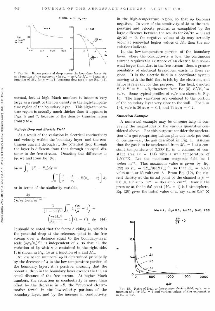
Voltage Drop and Electric Field
As a result of the variation in electrical conductivity and velocity within the boundary layer, and the continuous current through it, the potential drop through the layer is different from tha t through an equal distance in the free stream. Denoting this difference as 50, we find from Eq. (5),
50 - ; ;
(E Em)dy =
J o Lo" - - B(ua (TO
u) dy
or in terms of the similarity variable,
in the high-temperature region, so t ha t 50 becomes negative. In view of the sensitivity of 50 to the temperature and velocity profiles, as exemplified by the large difference between the results for bd/dx = 0 and bg/dx = 0, the negative values of 50 may actually occur at somewhat higher values of Mm than the calculations indicate.
In the low-temperature portion of the boundary layer, where the conductivity is low, the continuous current requires the existence of an electric field somewhat larger than tha t in the free stream; thus, a greater possibility of electrical breakdown exists in these regions. I t is the electric field in a coordinate system moving with the fluid t ha t is felt by the electrons, and hence is relevant for this purpose. This field, denoted £ ' , is E' = E - uB; therefore, from Eq. (5), E'/EJ = (TQ/a. Some typical profiles of ao/a are shown in Fig. 15. The large variations are confined to the portion of the boundary layer very close to the wall. For n = 1/4, ao/a is 36 at 77 = 0.1, and 11 at T? - 0.2.
Numerical Example
A numerical example may be of some help in conveying the magnitudes of the various quantities considered above. For this purpose, consider the acceleration of a gas comprising helium plus one mole per cent of cesium—i.e., the gas described in Fig. 1. Assume tha t the gas is to be accelerated from Mm = 1 a t a cons tant temperature of 3,000°K, in a channel of cons tant area (n = 1/4) with a wall temperature of 1,500°K. Let the maximum magnetic field be 1 weber m~2 . This maximum value is given by Eq. (22) as Bm = 2EjS(3RTaiy
/2, so t ha t Em = 6,500 volts m _ 1 , or 65 volts c m - 1 . F rom Eq. (19), the current density at the initial point of the channel is jo = 3.6 X 10⁶ amp. m~2 = 360 amp. cm" 2 . Now if the pressure at the initial point (M«> = 1) is 1 atmosphere, Eq. (20) gives the initial value of x, say x0, as 0.57 X
(JoAo)(WoAo)1/2
1 fVf! A (i - 2nyi2 Jo \<T J
/yrjMJ_ \bn - 1 1 ( i - / 0 drj (44)
I t should be noted tha t the factor dividing 50, which is the potential drop at the reference point in the free stream over a distance equal to the boundary-layer scale (VOXQ/UQ)I/2, is independent of x, so t ha t all the variation of 50 with x is contained in the right side. I t is shown in Fig. 14 as a function of n and M^.
At low Mach numbers, 50 is determined principally by the decrease of a in the low-temperature portion of the boundary layer; it is positive, meaning tha t the potential drop in the boundary layer exceeds tha t in an equal distance of the free stream. At higher Mach numbers, the reduction in conductivity is more than offset by the decrease in uB, the ' 'reversed electromotive force" in the low-velocity portions of the boundary layer, and by the increase in conductivity
M o o s l , 0*,= O.5, X = 7.5, 8 = 0.1766
d8 _ 0
2000
Cg/or
FIG. 15. Ratio of local to free-stream electric field, aQ/a, as a function of 77 for Mm = 1 and various values of the exponent n in Woo = axn.
Dow
nloa
ded
by U
NIV
ER
SIT
Y O
F C
AL
IFO
RN
IA -
DA
VIS
on
Febr
uary
1, 2
015
| http
://ar
c.ai
aa.o
rg |
DO
I: 1
0.25
14/8
.911
7
D I R E C T - C U R R E N T P L A S M A A C C E L E R A T O R S 643
10~2 m, and in a length of 0.1 m. (10 cm.) a velocity of 6,650 m/sec, or a Mach number of 2.1, would be attained.
The displacement thickness <5* a t x0 would be 0.74 X 10~4 m or 0.74 m m and, from Eq. (41) and Fig. 11, the heat-transfer ra te qw would be 0.301 X 10⁸ wat ts m - 2 . From Eq. (44) and Fig. 14, the excess voltage drop across the boundary layer would be 45 volts.
The difficulty of cooling a wall with a heat-transfer rate of the magnitude given above is quite clear. For example, to pass this heat flux through a t an ta lum wall would require a temperature drop of 1,000°K in a thickness of about 0.2 cm. Assuming for the moment t ha t such a heat flux can be maintained, one may ask how the power withdrawn by cooling compares with t ha t added by the current and magnetic field. For a channel half-height of 1 cm, the power input based on free-stream conditions, a t xo, would be 2.3 X 10⁸
watts m~2 , and with the additional potential drop in the boundary layer included, it would be 3.9 X 10⁸
watts m^ 2 . These power inputs are 7.6 and 13 times the cooling power. Thus, the efficiency of conversion of electrical energy to jet kinetic energy, based on the conditions at M^ = 1, would be about 0.92.
Concluding Remarks
One of the phenomena tha t are likely to occur at the surface of a cooled electrode in a hot, flowing plasma has been considered in some detail. As expected, the results show t h a t the current flowing normal to the electrode surface should cause a considerable increase in the heat-transfer ra te over t ha t which would exist without the current.
The heat-transfer rates are in fact so high tha t if operation at high pressures is necessary for suppression of the Hall effect, then some means of cooling the electrode other than simple conduction may be required. Aspiration cooling, either by the gas to be accelerated or by an alkali metal such as lithium, may be a possibility. T h e lat ter seems particularly at t ract ive because of the possibility of lowering the work function of the electrode surface. These techniques are susceptible to analysis by the present methods, and seem worthy of study.
At pressure levels below about 0.01 atmosphere, the length of the electron mean free path, as compared to the boundary-layer thickness, invalidates the present t rea tment . Under these conditions, the departure of the electrons from equilibrium must be explicitly considered. In addition, the Hall effect is likely to have a large influence on the character of the boundary layer.
References 1 Kerrebrock, Jack L., and Marble, Frank E., Constant-
Temperature Magneto-Gasdynamic Channel Flow, Readers' Forum, Journal of the Aero/Space Sciences, January 1960.
2 Kerrebrock, Jack L., Similar Solutions for Boundary Layers in Constant-Temperature Magneto-Gasdynamic Channel Flow,
Readers' Forum, Journal of the Aero/Space Sciences, February 1960.
3 Finkelnburg, W., and Maecker, H., "Elektrische Bogen und Thermisches Plasma," Handbuch der Physik, Band XXI I , p. 325: Springer Verlag, Berlin Gottingen, Heidelberg, 1956.
4 Chapman, S., and Cowling, T. G., The Mathematical Theory of Non- Uniform, Gases, Cambridge University Press, 1958.
5 Brown, Sanborn C , "Conduction of Electricity in Gases," Handbook of Physics; McGraw-Hill Book Co., Inc., New York, 1958.
6 Wood, G. P., and Carter, A. F., Considerations in the Design of a Steady B.C. Plasma Accelerator, American Rocket Society-— Northwestern Gas Dynamics S3^mposium, Northwestern University, Evanston, Illinois, August 24-26, 1959.
7 Levy, S., Effect of Large Temperature Changes (Including Viscous Heating) Upon Laminar Boundary Layers with Variable Free-Stream Velocity, Journal of the Aeronautical Sciences, Vol. 21, No. 7, pp. 459-474, July 1954.
+ + +
Magnetohydrodynamics (Continued from page 621)
in low frequencies, in which case the twisting length Lt of the modified Alfven wave is approximately given by :
L/Lt « (l/2)(co,/o>,0) with Z « (2T/cot)A0
For example, going back to the wavy-wall problem for crossed fields and large Rm, where the Alfven mechanism obviously plays an important role, i t is realized tha t the peculiar Hall-current pat tern shown in Fig. 6 must be closely related to the twisting of the plane of polarization of the modified Alfven wave. In fact, it is easily shown tha t the distance L/, shown in Fig. 6, is given by
L% = Lt cos \j/ where cos ^ = m/(\ + m2)1/2 (51)
In the wavy-wall problem, it may be noted, the wave normal forms an angle \j/ with the magnetic lines of force (see Fig. 6), which gives rise to the factor cos \p i n E q . (51).
Finally, it should be mentioned tha t damping of the waves discussed above can be studied by including the imaginary term in Eq. (48). In the low-frequency limit the damping of the modified Alfven wave is found to be the same as tha t of the classical plane Alfven wave.
Concluding Remarks
The present investigation was carried out as a first step towards a better understanding of Hall-current phenomena in engineering applications of magneto-hydrodynamics. Despite the simplifying assumptions of inviscid, incompressible flow and full ionization, the problems treated here are believed to elucidate some important features of real tensor-conductivity gas flow; viz., the formation of Hall-current loops, the
Dow
nloa
ded
by U
NIV
ER
SIT
Y O
F C
AL
IFO
RN
IA -
DA
VIS
on
Febr
uary
1, 2
015
| http
://ar
c.ai
aa.o
rg |
DO
I: 1
0.25
14/8
.911
7
644 J O U R N A L O F T H E A E R O S P A C E S C I E N C E S - A U G U S T 1 9 6 1
influences of geometry, Alfven number, and magnetic Reynolds number on the magnitudes of tensor-conductivity effects, and finally Alfven-wave propagation and the role played by modified Alfven waves in the creation of certain Hall-current patterns.
References 1 Cowling, T. G., Magnetohydrodynamics, pp. 99-108; Inter-
science Publishers, Inc., New York, 1957. 2 Spitzer, L., Jr., Physics of Fully Ionized Gases, pp. 18-23;
Interscience Publishers, Inc., New York, 1956. 3 Kemp, N. H., and Petschek, H. E., Two-dimensional Incom
pressible Magnetohydrodynamic Flow across an Elliptical Solenoid, J. Fluid Mech., Vol. 4, Part 6, pp. 553-584, November, 1958.
4 Sears, W. R., and Resler, E. L., Theory of Thin Airfoils in Fluids of High Electrical Conductivity, J. Fluid Mech., Vol. 5, Part 2, pp. 257-273, February 1959.
5 Resler, E. L., and McCune, J. E., "Electromagnetic Interaction with Aerodynamic Flows," pp. 120-136, The Magneto-dynamics of Conducting Fluids, D. Bershader, Ed.; Stanford Univ. Press, Stanford, 1959.
6 Astrom, E., On Waves in an Ionized Gas, Arkiv for Fysik (Kungl. Svenska Vetenskapsakademien), Vol. 2, No. 5, pp. 443-457, January 1951.
7 Sonnerup, B., Some Effects of Tensor Conductivity in Magnetohydrodynamics, M. Aero. Engr. Thesis, Cornell Univ. Grad. School of Aero. Engrg., Ithaca, N. Y., 1960.
8 Grad, H., Notes on Magnetohydrodynamics IV~Ohm's Law, New York University AEC Research and Development Report NYO 6486, August 20, 1956.
9 Schliiter, A., Dynamik des Plasmas-—I, Zeitschrift fur Naturforschung, Band 5a, Heft 2, pp. 72-78, 1950.
10 Lin, S. C , Resler, E. L., and Kantrowitz, A., Electrical Conductivity of Highly Ionized Argon Produced by Shock Waves, J. Appl. Phys., Vol. 26, No. 1, January 1955.
+- +
A Reprint
Journal of the Aeronautical Sciences N o w e n t i t l e d Journal of the A e r o s p a c e Sc i ences
Available
Volumes 1-5, 1934-1937/1938, paper bound set $140.00 Volumes 1-2, 1934-1935, single volumes, paper bound 20.00 Volumes 3-5, 1935/1936-1937/1938, single volumes, paper bound 35.00
In Preparation
Volumes 6-8, 1938/1939-1940/1941
(Reproduced with the permission of the original publisher, Institute of the Aerospace Sciences, Inc.)
Please address orders and inquiries to:
Johnson Reprint Corporation 111 Fifth Avenue, New York 3, N.Y.
+ +
Cha nge of Address
Since the Post Office Department does not as a rule forward magazines to forwarding addresses, it is important that the Institute be notified of changes in address 30 days in advance of publishing date to ensure receipt of every issue of the JOURNAL and AEROSPACE ENGINEERING. Notices should be printed legibly and sent to:
Circulation Department Institute of the Aerospace Sciences, Inc. 2 East 64th Street, New York 2 1 , N.Y.