CHAPTER 3 60-mm MORTAR, M224 The 60-mm mortar, M224, reacts quickly to support infantrymen by engaging the target first. This allows infantrymen to confront the enemy while supporting the battle plan. The mortar can be fired accurately with or without a fire direction center. Section I. SQUAD AND SECTION ORGANIZATION AND DUTIES This section discusses the organization and duties of the 60-mm mortar squad and section. 3-1. ORGANIZATION If the mortar section is to operate quickly and effectively in accomplishing its mission, mortar squad members must be proficient in individually assigned duties. Correctly applying and performing these duties enables the mortar section to perform as an effective fighting team. The section leader commands the section and supervises the training of the elements. He uses the chain of command to assist him in effecting his command and supervising duties. 3-2. DUTIES The mortar squad consists of three soldiers. Each squad member is cross-trained to perform all duties involved in firing the mortar. The positions and principal duties are as follows: a. The squad leader is in position to best control the mortar squad. He is positioned to the right of the mortar, facing the barrel. He is also the FDC. b. The gunner is on the left side of the mortar where he can manipulate the sight, elevating gear handle, and traversing assembly wheel. He places firing data on the sight and lays the mortar for deflection and elevation. Assisted by the squad leader (or ammunition bearer), he makes large deflection shifts by shifting the bipod assembly. c. The ammunition bearer is to the right rear of the mortar. He prepares the ammunition and assists the gunner in shifting and loading the mortar. He swabs the barrel every 10 rounds or after each end of mission.
Transcript
CHAPTER 3
60-mm MORTAR, M224
The 60-mm mortar, M224, reacts quickly to support infantrymen by engaging the target first. This allows infantrymen to confront the enemy while supporting the battle plan. The mortar can be fired accurately with or without a fire direction center.
Section I. SQUAD AND SECTION ORGANIZATION AND DUTIES
This section discusses the organization and duties of the 60-mm mortar squad and section.
3-1. ORGANIZATION
If the mortar section is to operate quickly and effectively in accomplishing its mission, mortar squad members must be proficient in individually assigned duties. Correctly applying and performing these duties enables the mortar section to perform as an effective fighting team. The section leader commands the section and supervises the training of the elements. He uses the chain of command to assist him in effecting his command and supervising duties.
3-2. DUTIES
The mortar squad consists of three soldiers. Each squad member is cross-trained to perform all duties involved in firing the mortar. The positions and principal duties are as follows:
a. The squad leader is in position to best control the mortar squad. He is positioned to the right of the mortar, facing the barrel. He is also the FDC.
b. The gunner is on the left side of the mortar where he can manipulate the sight, elevating gear handle, and traversing assembly wheel. He places firing data on the sight and lays the mortar for deflection and elevation. Assisted by the squad leader (or ammunition bearer), he makes large deflection shifts by shifting the bipod assembly.
c. The ammunition bearer is to the right rear of the mortar. He prepares the ammunition and assists the gunner in shifting and loading the mortar. He swabs the barrel every 10 rounds or after each end of mission.
Section II. COMPONENTS
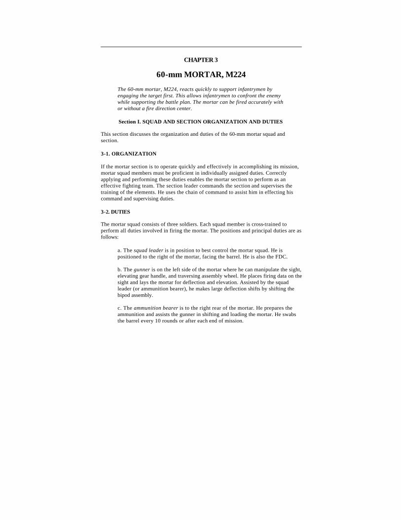
The 60-mm mortar, M224, can be fired in the conventional mode or handheld mode (Figure 3-1). The mortar is a muzzle-loaded, smooth-bore, high-angle-of-fire weapon. It can be drop-fired or trigger-fired and has five major components.
Figure 3-1. The 60-mm mortar, M224, (handheld mode and conventional mode).
3-3. TABULATED DATA
The tabulated data of the 60-mm mortar are as shown in Table 3-1.
HE (M888) HE (M720) HE (M49A4) WP (M302A1) Illum (M83A3) TP (M766) SRTR
70 meters
3,490 meters 70 to 3,490 meters 70 to 3,490 meters 44 to 1,930 meters 33 to 1,630 meters 725 to 951 meters 56 to 538 meters
75 meters
1,340 meters 70 to 1,340 meters 70 to 1,340 meters
50 to 1,300 meters (charge 3)
45 to 1,200 meters (charge 3)
725 to 750 meters (charge 2)
RATE OF FIRE
Maximum
M720/M888 M49A4
Sustained M720/M888 M49A4
30 rounds for first 4
minutes
30 rounds for 1 minute; 18 rounds for next 4 minutes
20 rounds per minute
indefinitely
8 rounds per minute indefinitely
No limit at charges 0 and 1
TYPE OF FIRE Drop-fire Drop-fire (charges 0 and 1 only)
Trigger-fire*
CARRYING OPTIONS One-man carry Two-man carry
One-man carry
Two-man carry Three-man carry
*Do not trigger-fire above charge 1.
Table 3-1. Tabulated data.
3-4. CANNON ASSEMBLY, M225
The cannon assembly (Figure 3-2) has one end closed by a base cap. The base cap end of the cannon has cooling fins on the outside, which reduce heat generated during firing. Attached to the base cap end is a combination carrying handle and firing mechanism. The carrying handle has a trigger, firing selector, range indicator, and auxiliary carrying handle. On the outside of the barrel is an upper and a lower firing saddle. The lower saddle is used when firing at elevations of 1100 to 1511 mils; the upper saddle is used when firing at elevations of 0800 to 1100 mils.
Figure 3-2. Cannon assembly, M225.
Note : When the bipod is positioned in the upper saddle, one turn of the traversing handwheel will move the barrel 10 mils. When the bipod is positioned in the lower saddle, one turn of the traversing handwheel will move the barrel 15 mils.
3-5. BASEPLATE, M7
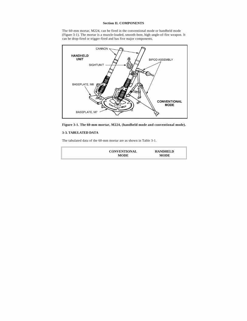
The baseplate, M7, (Figure 3-3) is a one-piece, circular, aluminum-forging base. It has a ball socket with a rotating locking cap and a stationary retaining ring held in place by four screws and lock washers. The locking cap rotates 6400 mils, giving the mortar full-circle firing capability. The underside of the baseplate has four spades to stabilize the mortar during firing.
Figure 3-3. Baseplate, M7.
3-6. BASEPLATE, M8
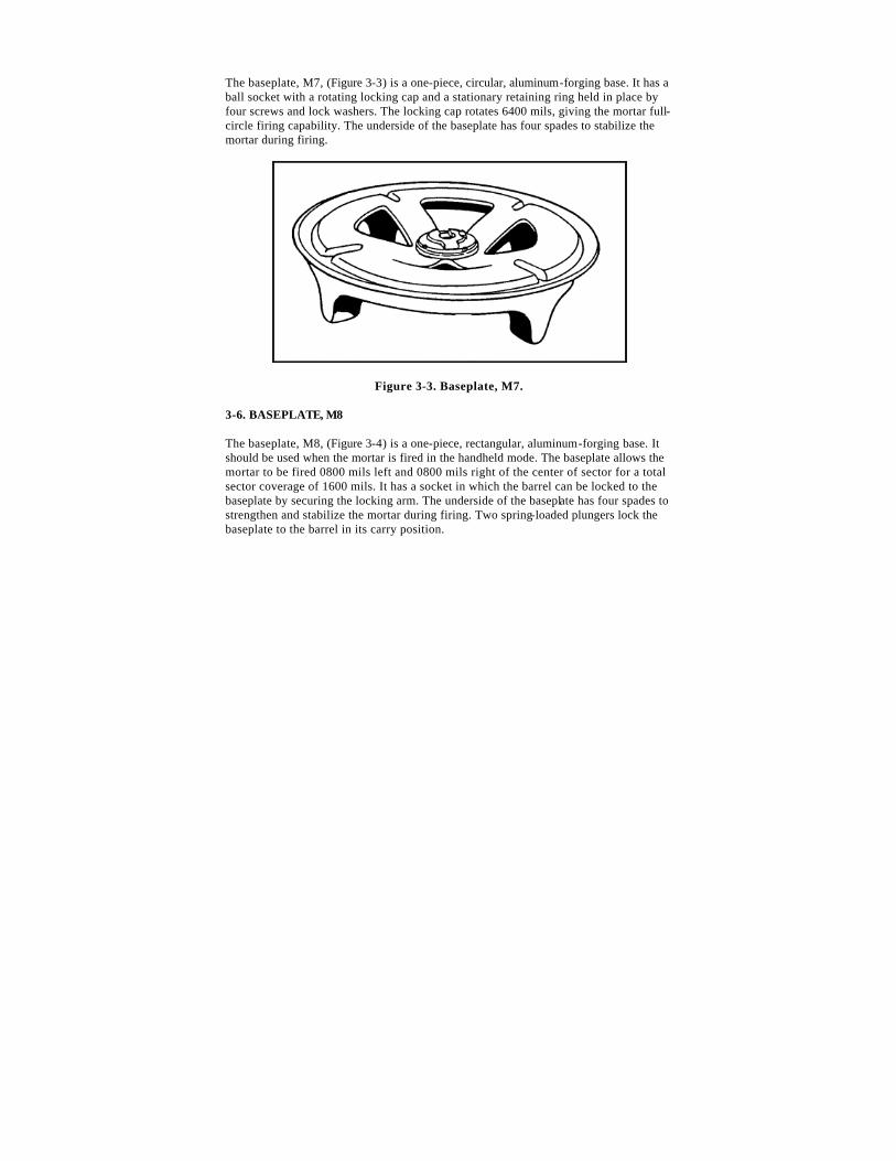
The baseplate, M8, (Figure 3-4) is a one-piece, rectangular, aluminum-forging base. It should be used when the mortar is fired in the handheld mode. The baseplate allows the mortar to be fired 0800 mils left and 0800 mils right of the center of sector for a total sector coverage of 1600 mils. It has a socket in which the barrel can be locked to the baseplate by securing the locking arm. The underside of the baseplate has four spades to strengthen and stabilize the mortar during firing. Two spring-loaded plungers lock the baseplate to the barrel in its carry position.
Figure 3-4. Baseplate, M8.
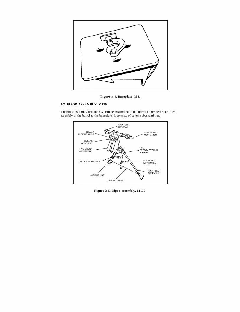
3-7. BIPOD ASSEMBLY, M170
The bipod assembly (Figure 3-5) can be assembled to the barrel either before or after assembly of the barrel to the baseplate. It consists of seven subassemblies.
Figure 3-5. Bipod assembly, M170.
a. Collar Assembly. The collar assembly, with an upper and lower half, is hinged on the left and secured by a locking knob on the right. The collar fastens in one of the two firing saddles (depending on the elevation being fired), securing the bipod to the barrel.
b. Shock Absorbers . Two shock absorbers located on the underside of the collar assembly protect the bipod and sight from the shock of recoil during firing.
c. Traversing Mechanism. The traversing mechanism moves the collar assembly left or right when the traversing hand crank is pulled out and turned. The hand crank is turned clockwise to move the barrel to the right, and counterclockwise to move the barrel to the left. The left side of the traversing mechanism has a dovetail slot to attach the sight to the bipod.
d. Elevating Mechanism. The elevating mechanism is used to elevate or depress the barrel by turning the hand crank at the base of the elevation guide tube. This assembly consists of an elevating spindle, screw, hand crank, and housing (elevation guide tube). The housing has a latch to secure the collar and shock absorbers to the housing for carrying. The hand crank is turned clockwise to depress, and counterclockwise to elevate.
e. Right Leg Assembly. The right leg assembly has no moving parts. It consists of a foot, tubular steel leg, and hinge attached to the elevating mechanism housing.
f. Left Leg Assembly. The left leg assembly consists of a foot, tubular steel leg, hinge attached to the elevating mechanism housing, locking nut, and fine cross-leveling sleeve.
(1) The locking sleeve is near the spiked foot. It is used to lock the elevation housing in place.
(2) The fine cross-leveling nut above the locking sleeve is used for fine leveling.
g. Spread Cable. The spread cable is a plastic-coated steel cable attached to the bipod legs, which controls the spread of the two tubular steel legs. A snap hook is fixed to the cable to secure the bipod legs when they are collapsed for carrying.
Section III. OPERATION
Safe operation of the 60-mm mortar requires that training include drill practice on tasks for safe manipulation and effective employment. Crew training achieves the speed, precision, and teamwork needed to deliver responsive and effective fire on target.
3-8. PREMOUNT CHECKS
Before the mortar is mounted, the squad must perform premount checks. Each squad member should be capable of performing all the premount checks.
a. The gunner performs the premount checks on the mount so that--
• The spreader cable is fixed to both legs and taut. • The clearance on the left leg above the adjusting nut is two fingers in
width. • The locking sleeve is neither too loose nor too tight. • The traversing bearing is centered.
b. The squad leader performs the premount checks on the barrel so that--
• The barrel is clean both inside and outside. • The firing pin is visible. • The spherical projection is clean, and the firing pin is firmly seated. • The selector switch is on drop-fire mode.
c. The ammunition bearer is responsible for the premount checks on the baseplate ensuring that--
• The rotatable socket cap moves freely and has a light coat of oil. • The ribs and braces are checked for breaks and dents, and the inner ring is
secured to the outer ring.
d. When all pieces of equipment are checked, the gunner notifies the section leader by announcing, "All correct."
3-9. MOUNTING OF THE MORTAR
The squad leader picks up and places the sight case and two aiming posts at the exact position where the mortar is to be mounted.
a. The ammunition bearer places the outer edge of the baseplate against the baseplate stake. He aligns the left edge of the cutout portion of the baseplate with the right edge of the baseplate stake. He then rotates the socket cap so that the open end points in the direction of fire.
b. The gunner picks up the bipod with his left hand on the traversing hand crank and his right hand on the dovetail slot. He moves forward of the baseplate about 12 to 15 inches and faces the baseplate on line with the left edge (gunner’s viewpoint) of the baseplate. Dropping down on one knee in front of the bipod, the gunner supports the bipod with his left hand on the gear case. He then detaches the hook and unwraps the cable assembly. The gunner places his left hand on the midsection of the traversing slide and his right hand on the mechanical leg, and he extends the bipod legs the length of the cable assembly. He then aligns the center
of the bipod assembly with the center of the baseplate. He ensures that the elevation guide barrel is vertical and the locking nut is hand tight. The gunner moves to the mechanical leg side and supports the bipod with his left hand on the shock absorber. He unscrews the collar locking knob to open the collar.
c. The ammunition bearer picks up the barrel and inserts the spherical projection of the base plug into the socket. He rotates the barrel 90 degrees to lock it to the baseplate. If performed properly, the carrying handle is on the upper side of the barrel, facing skyward.
d. The gunner pushes down on the shock absorber and raises the collar assembly. The ammunition bearer lowers the barrel and places the lower saddle on the lower part of the collar. The gunner closes the upper part of the collar over the barrel. He replaces the locking knob to its original position and makes it hand tight. The ammunition bearer cranks the elevation hand crank up 15 to 17 turns.
e. The gunner takes the sight out of the case and sets a deflection of 3200 mils and an elevation of 1100 mils. He mounts the sight to the mortar by pushing the lock latch on the sight inward. He slides the dovetail on the sight into the dovetail slot on the bipod until firmly seated. The gunner releases the latch. He should tap up on the bottom of the sight to ensure proper seating. He then levels the mortar first for elevation 1100 mils, and then cross-levels. The gunner announces, "(gun number) up," to his squad leader.
3-10. SAFETY CHECKS BEFORE FIRING
Safety checks are performed by the entire squad.
a. The gunner ensures that--
(1) There is mask and overhead clearance.
(a) Since the mortar is normally mounted in defilade, there could be a mask such as a hill, trees, buildings, or a rise in the ground. Roofs or overhanging tree branches can cause overhead interference. The gunner must be sure the round does not strike any obstruction.
(b) When selecting the exact mortar position, the squad leader checks quickly for mask and overhead clearance. After the mortar is mounted, the gunner checks it thoroughly. He determines mask and overhead clearance by sighting along the top of the barrel with his eye placed near the base plug. If the line of sight clears the mask, it is safe to fire. If not, he may still fire at the desired range by selecting a charge zone having a higher elevation for that particular range. When firing under the control of an FDC, the
gunner reports to the FDC that mask clearance cannot be obtained at a certain elevation.
(c) Firing is slowed if mask clearance is checked before each firing. Therefore, if the mask is not regular throughout the sector of fire, the minimum mask clearance is determined to eliminate the need for checking on each mission. To do this, the gunner depresses the barrel until the top of the mask is sighted. He then levels the elevation bubble and reads the setting on the elevation scale and elevation micrometer. That setting is the minimum mask clearance. The gunner notifies the squad leader of the minimum mask clearance elevation. Any target that requires that elevation or lower cannot be engaged from that position.
(d) Placing the mortar in position at night does not relieve the gunner of the responsibility for checking for mask and overhead clearance.
(2) The barrel is locked to the baseplate and the open end of the socket cap points in the direction of fire. The bipod should be connected to either the upper or lower saddle of the barrel.
(3) The barrel is locked on the collar by the locking knob.
(4) The locking nut is wrist tight.
(5) The cable is taut.
(6) The selector switch on the barrel is on drop-fire.
b. One crewman ensures that the bore is clean; he swabs the bore dry.
c. The second crewman ensures that each round is clean, safety pin is present, and ignition cartridge is in proper condition.
3-11. SMALL DEFLECTION AND ELEVATION CHANGES
With the mortar mounted and the sight installed, the gunner lays the sight on the two aiming posts (placed out 50 and 100 meters from the mortar) on a referred deflection of 2800 mils and an elevation of 1100 mils. The mortar is within two turns of center of traverse. The vertical cross line of the sight is on the left edge of the aiming post.
a. The gunner is given a deflection change in a fire command between 20 and 60 mils. The elevation change announced must be less than 90 mils and more than 35 mils.
b. As soon as the sight data are announced, the gunner places it on the sight, lays the mortar for elevation, and then traverses onto the aiming post by turning the traversing handwheel and the adjusting nut in the same direction. A one-quarter turn on the adjusting nut equals one turn of the traversing handwheel. When the gunner is satisfied with his sight picture he announces, "Up."
Note : The gunner repeats all elements given in the fire command.
c. After the gunner has announced "Up," the mortar should be checked by the squad leader to determine if the exercise was performed correctly.
3-12. LARGE DEFLECTION AND ELEVATION CHANGES
With the mortar mounted and the sight installed, the gunner lays the sight on the two aiming posts (placed out 50 and 100 meters from the mortar) on a referred deflection of 2800 mils and an elevation of 1100 mils.
a. The gunner is given a deflection and elevation change in a fire command causing the gunner to shift the mortar between 200 and 300 mils and an elevation change between 100 and 200 mils.
b. As soon as the sight data are announced, the gunner places it on the sight, elevates the mortar until the elevation bubble floats freely, and then centers the traversing bearing. If the elevation is between 1100 to 1511 mils, the cannon is mounted in the lower saddle. If the elevation is between 0800 to 1100 mils, the high saddle is used. If the saddle is changed, the squad leader helps the gunner.
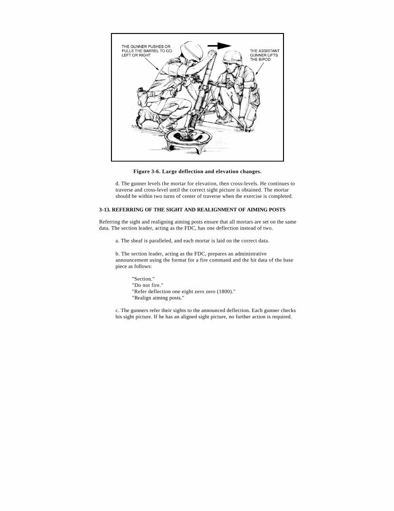
c. The squad leader moves into position to the front of the bipod on either knee and grasps the bipod legs (palms out), lifting until the feet clear the ground enough to permit lateral movement. The gunner moves the mortar as the squad leader steadies it, attempting to horizontally maintain the traversing mechanism. To make the shift, the gunner places the fingers of his right hand in the muzzle (Figure 3-6) and his left hand on the left leg, and moves the mortar until the vertical line of the sight is aligned approximately on the aiming post. When the approximate alignment is completed, the gunner signals the squad leader to lower the bipod by pushing down on the mortar.
Figure 3-6. Large deflection and elevation changes.
d. The gunner levels the mortar for elevation, then cross-levels. He continues to traverse and cross-level until the correct sight picture is obtained. The mortar should be within two turns of center of traverse when the exercise is completed.
3-13. REFERRING OF THE SIGHT AND REALIGNMENT OF AIMING POSTS
Referring the sight and realigning aiming posts ensure that all mortars are set on the same data. The section leader, acting as the FDC, has one deflection instead of two.
a. The sheaf is paralleled, and each mortar is laid on the correct data.
b. The section leader, acting as the FDC, prepares an administrative announcement using the format for a fire command and the hit data of the base piece as follows:
"Section." "Do not fire." "Refer deflection one eight zero zero (1800)." "Realign aiming posts."
c. The gunners refer their sights to the announced deflection. Each gunner checks his sight picture. If he has an aligned sight picture, no further action is required.
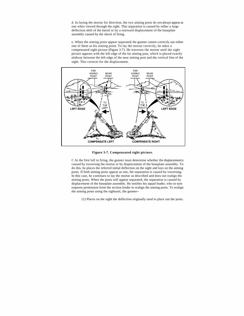
d. In laying the mortar for direction, the two aiming posts do not always appear as one when viewed through the sight. This separation is caused by either a large deflection shift of the barrel or by a rearward displacement of the baseplate assembly caused by the shock of firing.
e. When the aiming posts appear separated, the gunner cannot correctly use either one of them as his aiming point. To lay the mortar correctly, he takes a compensated sight picture (Figure 3-7). He traverses the mortar until the sight picture appears with the left edge of the far aiming post, which is placed exactly midway between the left edge of the near aiming post and the vertical line of the sight. This corrects for the displacement.
Figure 3-7. Compensated sight picture.
f. At the first lull in firing, the gunner must determine whether the displacement is caused by traversing the mortar or by displacement of the baseplate assembly. To do this, he places the referred initial deflection on the sight and lays on the aiming posts. If both aiming posts appear as one, the separation is caused by traversing. In this case, he continues to lay the mortar as described and does not realign the aiming posts. When the posts still appear separated, the separation is caused by displacement of the baseplate assembly. He notifies his squad leader, who in turn requests permission from the section leader to realign the aiming posts. To realign the aiming posts using the sightunit, the gunner--
(1) Places on the sight the deflection originally used to place out the posts.
(2) Lays the mortar so that the vertical line of the sight is aligned on the left edge of the far aiming post.
(3) Without shifting the mortar, refers the sight until the vertical cross line falls on the left edge of the near aiming post. This actually measures the angle between the posts.
(4) With this last deflection set on the sight, re-lays the mortar until the vertical cross line is aligned on the far aiming post.
(5) Without shifting the mortar, refers the sight again to the original referred deflection used to place out the aiming posts. The line of sight, through the sight, is now parallel to the original line established by the aiming posts.
(6) Looking through the sight, directs the ammunition bearer to move the aiming posts so that they are realigned with the sight’s vertical line. The posts are now realigned to correct the displacement.
Note : This procedure is used only when displacement is so great that it is difficult to obtain a compensated sight picture.
3-14. MALFUNCTIONS
Mortarmen must be aware of the following malfunctions.
a. Misfire . A misfire is a complete failure to fire. It can be caused by a faulty firing mechanism or faulty element in the propelling charge explosive train. A misfire cannot be immediately distinguished from a delay in functioning of the firing mechanism or from a hangfire; therefore, it must be handled with care. All firing malfunctions should be considered a misfire. Mechanical malfunctions can be caused by a faulty wiring pin or by rounds lodged in the barrel because of burrs, excess paint, oversized rounds, or foreign matter in the barrel. Procedures for removing a misfire are discussed in paragraph 3-15.
b. Hangfire . A hangfire is a delay in the functioning of a propelling charge explosive train at the time of firing. In most cases, the delay ranges from a split second to several minutes. Thus, a hangfire cannot be distinguished immediately from a misfire.
c. Cookoff. A cookoff is a functioning of one or more of the explosive components of a round chambered in a hot weapon, initiated by the heat of the weapon.
3-15. REMOVAL OF A MISFIRE
The procedures for removing a misfire are different for handheld and conventional modes. The propelling charge may not function for the following reasons:
• Defective ignition cartridge. • Defective, damaged, or loose firing pin. • Fouled firing pin or firing pin obstructed by extraneous material. • Fouled bore. • Excess oil or water in the bore. • Misaligned stabilizing fin. • Foreign matter or excess paint on round. • Selector switch on SAFE or TRIGGER.
a. Conventional Mode .
(1) When a misfire occurs, any member of the squad immediately announces, "Misfire." The entire squad stays with the mortar. If it is obvious to the squad leader that the round has reached the bottom of the barrel and it has failed to ignite, the gunner places the selector switch on trigger fire and squeezes the trigger several times to try to clear the round.
WARNING
During peacetime live -fire training, the ammunition bearer moves at least 50 meters to the rear of the mortar.
Notes: 1. A faulty firing pin assembly on a 60-mm mortar, M224, requires that the firing pin be tightened upon completion of firing when frequent trigger firing using M720-, M721-, or M722-series ammunition. These type rounds usually fire when trigger fired.
2. In case of a hangfire, kick the cannon several times to dislodge the round.
CAUTION
Trigger fire the M720-series rounds with charges 0 and 1 only. If an emergency requires trigger fire above charge 1, the baseplate must be well seated and extreme caution taken.
(2) If the round fails on trigger fire, the gunner places the selector switch back on drop fire. Staying clear of the muzzle at all times, the squad leader holds the bipod legs to prevent slippage. The gunner strikes the barrel sharply several times with the heel of his boot just above the handle assembly. If the round fails to dislodge after trigger firing and kicking, the gunner places the selector switch on SAFE.
WARNING
During peacetime live -fire training, the gunner and squad leader join the ammunition bearer and wait one minute (in case of a cookoff). After waiting one minute, the gunner returns to the mortar.
(3) The gunner checks for heat by starting from just below the muzzle and working down to the base with his fingertips. If the barrel is too hot to be handled, he cools it with water (or snow) and checks it one minute later. If no water (or snow) is available, the barrel is air cooled until it can be easily handled with bare hands.
Notes: 1. Liquids must never be poured into the barrel.
2. During peacetime live-fire training, the gunner signals the squad leader to come forward once the barrel is cool.
(4) The gunner locks the data down on the sight, then removes the sight and places it in a safe location. He then lowers the barrel to its minimum elevation and backs off one-quarter turn. DO NOT MOVE THE BIPOD LEGS OR CHANGE THE FIRING SADDLE DURING THIS PROCEDURE. The gunner unlocks the barrel from the baseplate by loosening the locking knob until the barrel can be rotated. He rotates the barrel 90 degrees in the socket cap so that the flats on the barrel are aligned with the flats of the socket cap. The squad leader places his left leg in front of the nonmechanical leg of the bipod to keep the bipod steady during the misfire removal. After placing his leg in this position, the squad leader places his left hand near the top of the barrel and his right hand on the underside, just below the muzzle. He prevents any part of his body from passing in front of the muzzle.
WARNING
Once the barrel reaches the horizontal, it must not be lowered back down until the round is extracted. If the round slips down the barrel before extraction, it could ignite, causing death or personal injury.
(5) The gunner continues to raise the barrel so that the base of the barrel is higher than the top. With the muzzle pointing toward the ground, the gunner shakes it slightly to help dislodge the round. As the round starts to clear the muzzle, the squad leader squeezes his thumbs against the body of
the round--not the fuze--and removes it. If the round fails to come out once the barrel is lifted, the barrel is lowered back to the horizontal. It is removed from the bipod assembly and placed in a designated dud pit. EOD personnel are notified for removal or disposal.
(6) Once the round has been removed, the squad leader gives the round to the ammunition bearer who inspects it. The ammunition bearer replaces any safety pins and inspects the primer of the ignition cartridge. If dented, the round should not be fired. If the primer has not been dented, the firing pin on the mortar should be checked for proper seating and tightened down if needed.
(7) While the round is being inspected, the gunner lowers the barrel back into the baseplate and remounts the sightunit to the bipod. The ammunition bearer then swabs the bore, and the gunner re-lays the mortar on the previous firing data.
Note : If the baseplate moved during the misfire procedure, the mortar must be reciprocally laid.
(8) If the primer on the round has not been dented, the gunner tries to fire the round again. If the same round misfires, he repeats the misfire procedures. If the primer has been dented, he notifies organizational maintenance IAW unit SOP.
b. Handheld Mode .
(1) When a misfire occurs, any member of the squad immediately announces, "Misfire." The entire crew stays with the mortar, and the gunner immediately pulls the trigger twice. If the round still fails to function, he announces, "Misfire." The gunner places the selector switch on SAFE and bounces the mortar from at least 6 inches off the ground to dislodge the round. (Disregard if the crew heard the round strike the bottom of the barrel.)
WARNING
During peacetime live -fire training, the gunner stays with the mortar and all other crew members move at least 50 meters behind the mortar.
Note : The gunner bounces the mortar only if the round is between the muzzle and firing pin.
(2) The gunner places the selector switch back on trigger fire and squeezes the trigger twice--the mortar should fire. If the round does not fire, he places the selector switch on SAFE and supports the mortar barrel with sand bags, logs, or empty ammunition boxes to keep the barrel upright and stable. He ensures the barrel is up and pointing downrange. The gunner checks for heat with his fingertips only, starting just below the muzzle and working down to the base.
WARNING
During peacetime live -fire training, the gunner joins the rest of the squad and waits one minute.
(3) If the barrel is hot, the gunner cools it with water (or snow) and then rechecks for heat. If there is no water (or snow), he lets the barrel air cool until it can be easily handled with bare hands.
Note : During peacetime live-fire training, the gunner signals the squad to come forward once the barrel is cool.
(4) Once the barrel is cool, the squad leader places his left hand (fingers and thumb extended and together) near the top of the barrel and his right hand on the underside just below the muzzle. In one smooth motion, the gunner lifts the base of the mortar with the M8 baseplate to the horizontal position. Once the barrel reaches the horizontal position, the squad leader extends the meaty portion of his thumbs over the end of the muzzle. The gunner continues to raise the base of the barrel past the horizontal. With the muzzle pointing downward, the gunner slightly shakes the barrel to help dislodge the round. As the round starts to clear the muzzle, the squad leader catches the round by squeezing his thumbs against the sides of the body--not the fuze--and removes it. The squad leader passes it to the ammunition bearer. If the fuze has safety pins (other than the M734), he tries to replace them.
(5) The ammunition bearer inspects the primer of the ignition cartridge. If dented, he does not try to fire the round again. If the pins cannot be replaced, the fuze may be armed. He lays the round in the designated dud pit and notifies EOD personnel.
(6) If the round does not come out after lifting the barrel up and shaking it, the gunner returns the barrel to the horizontal. The squad leader places the barrel in the designated dud pit and notifies EOD personnel.
WARNING
Once the barrel reaches the horizontal, it must not be lowered back down until the round is extracted. If the round slips down the barrel before extraction, it could ignite, causing death or personal injury.
(7) If the primer on the round has not been dented, the gunner lifts the base as high as possible. He shakes the barrel to dislodge any debris and swabs the bore. He tries to fire the round again. If two misfires occur in a row without the primer being dented, the gunner notifies organizational maintenance IAW unit SOP.
3-16. DISMOUNTING AND CARRYING OF THE MORTAR
To dismount and carry the mortar, the squad leader commands OUT OF ACTION.
a. Dismounting. The ammunition bearer retrieves the aiming posts. The gunner removes the sight, places an elevation of 0800 mils and a deflection of 3200 mils on the M64 sightunit, and places it in the case. Then he lowers the mortar to its minimum elevation and backs off one-quarter turn. He then centers the traversing mechanism and unlocks the collar with the collar locking knob.
(1) The squad leader grasps the base of the barrel and turns it 90 degrees (a one-quarter turn), until the spherical projection is in the unlocked position in the baseplate socket. He then lifts up on the base end of the barrel and removes it from the collar assembly. The ammunition bearer secures the baseplate.
(2) The gunner relocks the collar with the collar locking knob. He moves to the front of the bipod and faces it, kneels on his right knee with his left hand on the gear case, and loosens the locking nut. He tilts the bipod to his left and closes the bipod legs, placing the cable around the legs and rehooking the cable. He stands up, placing his right hand on the sight slot and his left hand on the traversing handwheel.
(3) On the command MARCH ORDER, squad members take the equipment distributed to them by the squad leader and move.
b. Carrying. The mortar can be carried by one or two men for short distances. When the sight is left mounted on the mortar, care must be taken to prevent damaging it.
(1) For a one-man carry, the mortar is in the firing position with the mount attached to the barrel at the lower saddle. The elevating mechanism is
fully depressed, and the bipod legs are together. The mount is folded back underneath the barrel until the elevating mechanism latches to the collar assembly. The cable is passed through one of the baseplate openings and wrapped around the barrel. The cable is attached to itself, using its snap hook. The carrying handle is used to carry the complete mortar.
(2) For a two-man carry, the M7 baseplate is one load, and the barrel/mount combination is the second load. The mount is attached to the barrel at the lower saddle, and the elevating mechanism is fully depressed. The bipod legs are together, and the bipod is folded up under the barrel until the elevating mechanism latches to the collar assembly. The cable is wrapped around the legs and barrel and hooked onto itself with its snap hook.
Note : The carrying position can be in the upper or lower saddle, depending on the mission or enemy situation.
(3) For the handheld mode, the M8 baseplate is left attached to the barrel. The baseplate is rotated 90 degrees to the right and rotated up until the two spring plungers on the front edge of the baseplate body latch onto the protrusion on the right side of the basecap. Then the auxiliary carrying handle is placed in the carrying position.
Section IV. AMMUNITION
This section implements STANAG 2321 and QSTAG 900 (Edition 1).
The type of ammunition selected to engage targets depends on the elevation.
3-17. CLASSIFICATION
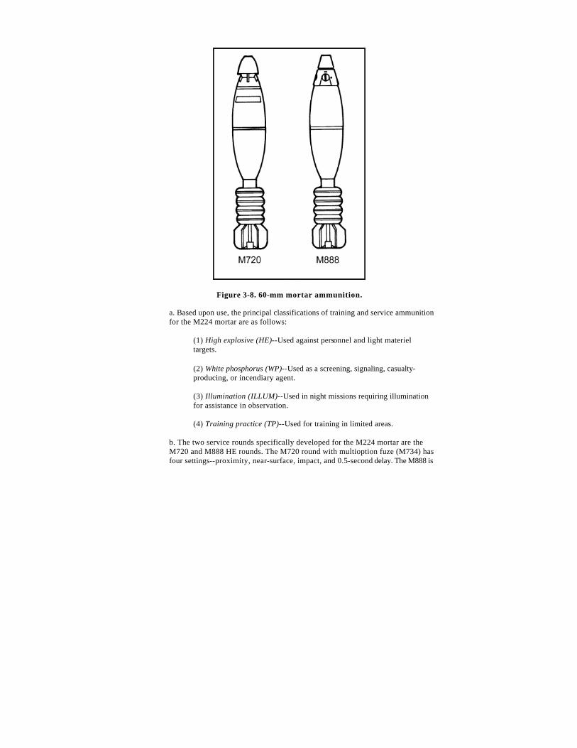
All 60-mm mortar rounds, except training rounds, have three major components--a fuze, body, and tail fin with propulsion system assembly (Figure 3-8).
Figure 3-8. 60-mm mortar ammunition.
a. Based upon use, the principal classifications of training and service ammunition for the M224 mortar are as follows:
(1) High explosive (HE)--Used against personnel and light materiel targets.
(2) White phosphorus (WP)--Used as a screening, signaling, casualty-producing, or incendiary agent.
(3) Illumination (ILLUM)--Used in night missions requiring illumination for assistance in observation.
(4) Training practice (TP)--Used for training in limited areas.
b. The two service rounds specifically developed for the M224 mortar are the M720 and M888 HE rounds. The M720 round with multioption fuze (M734) has four settings--proximity, near-surface, impact, and 0.5-second delay. The M888 is
a standard point-detonating fuze (M935) with both impact and 0.5-second delay settings.
Note : A marking round, M722, and an illumination round, M721, have been type-classified.
c. The ammunition designed for the M2 and M19 mortars can be fired from the M224 mortar. When fired from the M224 mortar, greater ranges are achieved than those shown in the M2 and M19 firing tables. Standard A ammunition for the M2 and M19 mortars is standard B for the M224 mortar. No more than two charges are used when firing the M720 or M999 in either of the 60-mm mortars.
Note : Firing Table 60-P-1 has been published for all ammunition fired in the M224 mortar.
3-18. COLOR CODES
Mortar ammunition is painted and marked with a color code for quick, accurate identification. A color-code chart (Table 3-2) identifies rounds using the NATO color code and the US color code.
NATO COLOR CODE US COLOR CODE TYPE OF ROUND
ROUND MARKINGS BAND ROUND MARKINGS BAND
HIGH EXPLOSIVE M720, M888, and M49A4 Causes troop casualties and damage to light material.
Olive Drab
Yellow
Drab
NA
Olive
Yellow
Yellow
WHITE PHOSPHORUS M302A1 M302A2 To screen, signal, and act as an incendiary.
Light Green
Red
Yellow
Gray
Yellow
Yellow
ILLUMINATION M83A3 M721 To illuminate, signal, and mark.
White
Black
NA
NA
NA
NA
TRAINING PRACTICE M69TP M50A3 M766 (SRTR) For training and practice.
Blue Blue Blue
White White White
NA
Brown NA
Blue Blue Blue
White White White
Brown
Table 3-2. Mortar ammunition color codes.
3-19. PREPARATION OF AMMUNITION
The ammunition bearer receives information in a fire command sent by the FDC and prepares the ammunition for firing. The number of rounds, type of round, fuze setting, and charge are all included in the fire command. To apply the data, the ammunition bearer selects the proper round, sets the fuze, and adjusts (removes or replaces) the charge on the quantity of rounds called for in the fire command. He also inspects each round for cleanliness and serviceability.
WARNING
For protection, a round(s) prepared but not fired should be returned to its container(s) increment end first. The pull wire on the M888 fuze must be replaced before returning it to its container.
The ammunition bearer should cut charges immediately in an FFE mission. In an adjust-fire mission, he should prepare the round and delay cutting the charges until FFE is entered. This is a precaution if the charge changes during adjustment.
3-20. TYPES OF FUZES
The two types of fuzes are the M734 multioption fuze and the M935 point-detonating fuze.
a. Multioption Fuze, M734. This fuze for the M720 HE round can be set to function as proximity burst, near-surface burst, impact burst, or delay burst (Figure 3-9). Tools are not needed to set this fuze. The setting can be changed any number of times before firing without damaging the fuze. The fuze has no safety pins or wires to reduce preparation time. The round bursts at 1 to 4 meters (3 to 13 feet) above the target. If a round set for proximity fails to burst at the proximity distance above the target, it automatically bursts at 0 to 1 meter (0 to 3 feet) above the target. If a round set for near-surface burst (NSB) fails to burst at the near-surface distance above the target, it automatically bursts on impact. If a round set for impact fails to burst on impact, it automatically bursts 0.5 (1/2) second after impact (delay).
Figure 3-9. Multioption fuze, M734.
b. Point-Detonating Fuze, M935. This fuze for the M888 HE round can be set to function as superquick (SQ) or delay (D) (Figure 3-10). It has a standard pull-wire safety that is removed immediately before firing.
Figure 3-10. Point-detonating fuze, M935.
3-21. STANDARD B AMMUNITION
Standard B ammunition, designed for the M2 and M19 mortars, fits the bore (diameter) of the M224. Since the M224 has a longer barrel, firing tables developed for the standard B ammunition are not accurate when standard B ammunition is fired in the M224.
a. The M720, M721, and M722 cartridges (designed specifically for M224 mortars) can be fired in the M19 mortar at reduced charges: maximum charge 2 for training and charge 3 in combat.
b. The standard B rounds shown in Figure 3-11 are available for training with the M224. Ranges given are for general reference and could vary from those actually obtained. Never fire over charge 1 for the M720 or M888 cartridge when using the M224 in the handheld mode. Using standard B ammunition, HE can be fired up to charge 3 and WP/ILLUM can be fired up to charge 2.
Figure 3-11. Standard B ammunition.
c. The M766 short -range training round (SRTR) cartridge (Figure 3-12) can be fired from the 60-mm mortar using standard sight and fire control equipment and firing table FT 60-P-1. A 60-mm subcaliber device can be inserted in the 4.2-inch mortar to fire the M766 (SRTR) for training 4.2-inch heavy mortar platoons.
Figure 3-12. M766 (SRTR) cartridge.
(1) The M766 (SRTR) cartridge weighs 2.9 pounds and is 11 inches long. It has a maximum range of 538 meters and a minimum range of 56 meters. The cartridge is blue with white markings and one brown band.
(2) The M766 (SRTR) uses an M779 PD fuze, which produces a visible flash, a cloud of smoke, and an audible sound on impact for spotting purposes. The M779 has multioption type (PRX/NSB/IMP/DLY) dummy settings to simulate an M734 multioption fuze.
3-22. CARE AND HANDLING
Ammunition is manufactured and packed to withstand all conditions normally encountered in the field. However, moisture and high temperature can damage ammunition. Also, explosive elements in primers and fuzes are sensitive to strong shock and high temperature. Complete cartridges being fired should be handled with care.
WARNING
Do not try to disassemble any fuze.
a. The moisture-resistant seal of the shipping container should not be broken until the ammunition is to be used. When a large number of cartridges (15 or more for each squad) are prepared before a combat mission, the cartridges may be removed from the shipping container and the propellant increments adjusted. Then the fin assemblies should be reinserted into the container to protect the propelling charges.
b. Ammunition should be protected from mud, dirt, sand, water, and direct sunlight. Cartridges must be free of such foreign matter before firing. Ammunition that is wet or dirty should be wiped off at once.
c. Before firing, the gunner must remove the safety wire of the M888. Safety wires should be reinserted into all cartridges that have been prepared for firing but not used. Powder increments that have been removed should be replaced. Cartridges should be returned to their original packing and marked accordingly. (These cartridges should be used first in subsequent firings.)
WARNING
Duds are cartridges that have been fired but have not exploded. Duds are dangerous and should not be handled by anyone other than a member of the EOD team.
d. Ammunition should always be stored under cover. When this is not possible, it is raised at least 6 inches (15 centimeters) off the ground and covered with a double thickness of tarpaulin. Trenches are dug around the ammunition pile for drainage. WP cartridges must be stored with the fuze end up.
(1) In combat, store ammunition underground such as in bunkers.
(2) In the field, use waterproof bags, ponchos, ground cloths, and dunnage to prevent deterioration of ammunition. Ensure that ammunition does not become water-soaked.
(3) In arctic weather, store the ammunition in wooden boxes or crates. Place the boxes or crates on pallets and cover them with a double thickness of tarpaulin.
WARNING
Do not walk on, tumble, drag, throw, roll, or drop ammunition. Ensure that ammunition is kept in original container until ready for use. Do not combine WP and HE in storage. Maintain compatibility and quantity of ammunition,