Merkel hydraulic components are suitable for a wide range of applications in hydraulics, for both light-duty and heavy-duty applications. Freudenberg Sealing Technologies (FST) offers a complete range of standard solutions and also special solutions customised for particular applications. The range includes seals, wipers and guide rings. The latest production technology guarantees the fastest possible availability. Even in less than 24 hours with Merkel Xpress.
HYDRAULICS
REQUIREMENTS
Operational reliability under different extreme loads such as:• High temperature fluctuations• Irregular duty cycles and maintenance• High lateral forces and deflections• Very dirty conditions• High system pressures and pressure peaks.
• Rod seals with high pressure resistance as primary or secondary seal
• Piston seals with integrated pressure activation grooves for high operational reliability with fast pressure changes
• Wipers with static sealing edge for reliable protec-tion against ingress of dirt
• Guides with patented profiling ensure even distribu-tion of stress
• Sealing rings for static sealing e.g. cylinder heads with end position damping
• Friction-optimised sealing systems with low stick-slip tendency
• Heavy-duty sealing systems with high operational reliability under shock pressures, high lateral forces and extreme temperatures
• Universal sealing systems for support cylinders with good static and dynamic tightness because of additional support edge and sealing edge.
APPLICATION AREAS
Merkel sealing components cover a wide range in modern hydraulics and are in use wherever safety and service requirements as well as costs are important.
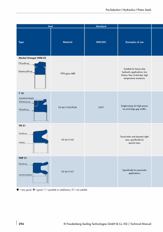
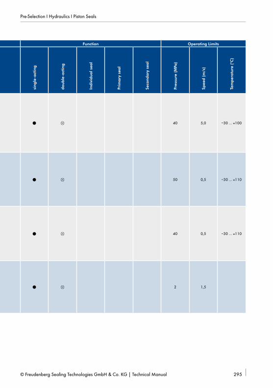
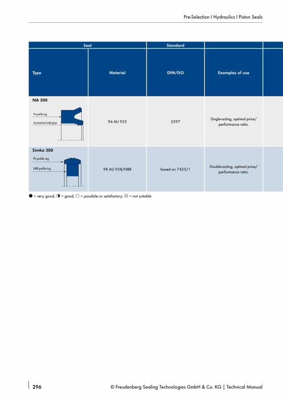
Different requirements and loads in numerous applica-tions have resulted in the development of different seal designs.Hydraulic seals can be categorised by function and design (→ Fig. 1).Hydraulic seals are also classified into seals with a sym-metrical cross-section and seals with an asymmetrical cross-section.
Asymmetrical seals are designed so the pre-load is distributed over the entire axial width on the supporting mating area to give them a sufficiently fixed seating in the groove. The correct pre-load on the moving side is not derived until after fitting in the housing (→ Fig. 2 and → Fig. 3).
In addition to the main requirement for a good sealing effect, the user expects the following from hydraulic seals:
• Functional reliability• Long service life• Easy fitting• Compatible with hydraulic fluid at high and
low temperatures• High resistance to mechanical damage
(e.g. gap extrusion)• Low friction• Good shape elasticity to ensure correct function,
even with eccentricity between rod and housing or piston and cylinder barrel caused by operation as well as the barrel widening as a result of the operat-ing pressure.
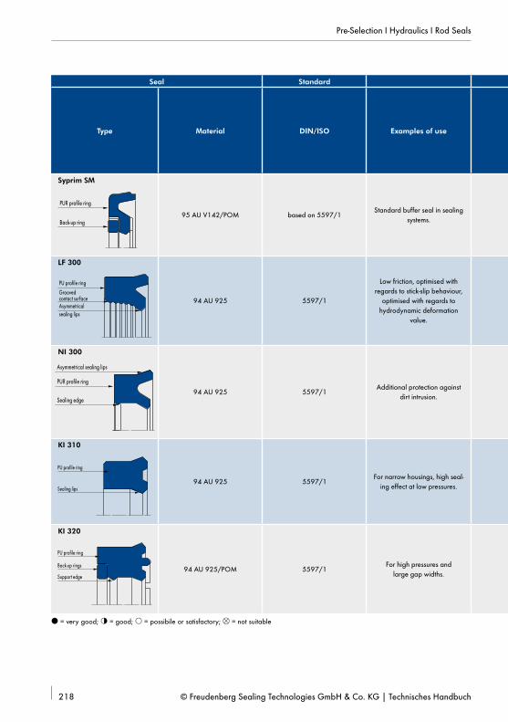
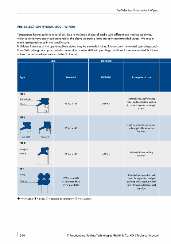
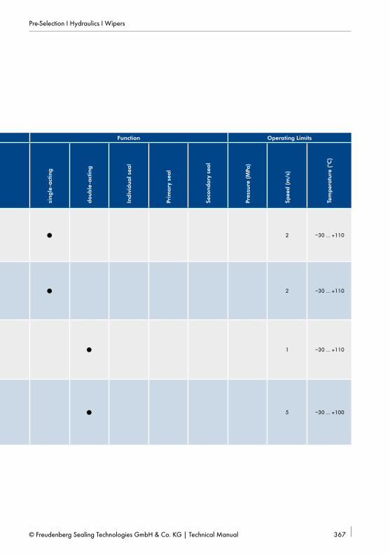
The weighting of the requirements for the specific ap-plication in combination with the operating conditions (pressure, temperature, sliding speed etc.) are the decisive factors affecting the selection of the seal.Types of seals can be preselected in the hydraulic seals product selection. → Preselection of hydraulic seals page 214.
With reference to the operating conditions the usage limits specified there can be exceeded in some cases. In the case of extended duty cycles, operation subject to shocks or other severe operating conditions we rec-ommend not exceeding all values simultaneously. Our technical consultants will be pleased to proved appropriate recommendations.
Sealing components are used to retain the hydraulic medium securely inside a hydraulic system. A defined moistening of the counter surface with lubricating me-dium is desirable when the required service life is taken into account. A sealing component is referred to in this regard as leaky if the hydraulic medium is visible from the outside in the form of dripping leakage.
REQUIREMENTS
During operation sealing components are subject to a reciprocating or rotary movement when operating pres-sure is applied. In addition to other influences, the selec-tion of a sealing component is significantly influenced by the material-dependent resistance against extrusion and the equally material-dependent friction and wear characteristics. The values of the main properties of sealing effect, form stability and friction or wear work against one another and in total cannot be optimally represented by one single sealing component. An ap-proximation of the ideal sealing component is reached with a reasonable combination of single components with appropriate properties into one sealing system.
ARRANGEMENT
Sealing systems generally consist of an arrangement of sealing components with a primary seal, a secondary seal, a wiper and guide elements (→ Fig. 4). The prop-erties of the individual components are optimised with reference to the main requirement.The operating pressure is applied to the primary seal. The main requirement is a high resistance against ex-trusion simultaneously with acceptable friction values under high pressure. Compact sealing components with a slip ring of PTFE compound are primarily used inside sealing systems. The remaining oil film is comparatively thick and without additional reduction by a secondary sealing component (depending on the operating pa-rameters) may be visible as dripping leakage in front of the wiper edge. The lower gap pressure (<5 MPa) is applied to the secondary seal. The main requirement is therefore effective reduction of the residual oil film left by the primary seal simultaneously with acceptable fric-tion values in the lower pressure range. With sufficient media resistance U-rings of polyurethane or compact sealing components with a slip ring of polyurethane are generally used in this case. The sealing effect is better with such sealing components compared to PTFE seal-ing components.
Analogy as per Prokop:The maximum pitch of the hilllimits the fluid transport
Fig. 5 Qualitative compression curve, single-acting rod seal
Depending on the requirements, wipers have different designs, such as single wiper or double wiper with extra sealing edge and are made of different materials. The outward aligned wiping edge keeps dirt from the environment outside the hydraulic system. A suitable design of the wiping edge (radius) ensures that the required lubricating film can be completely transport-ed on the return stroke. The additional sealing edge increases the operating reliability of the sealing system when required. The use of guide elements enables a low-friction and low-wear relative movement between the moving components of the hydraulic cylinder. The transverse loads occurring during operation are absorbed in a defined manner and prevent unwanted metal contact between the piston rod or the piston body and the surrounding housing components.
FUNCTION
To reduce friction and wear solid bodies that move rela-tive to one another must be separated by a lubricating film. The oil film left beneath the seal must be complete-ly transported back into the hydraulic system at every cycle. Inside a sealing system all individual seals and the wiper must meet these conditions.The formation of the hydrodynamic lubricating film is influenced by the design of the sealing edge (pressure movement), the operating pressure and the magnitude
and direction (extending or retracting) of the relative movement as well as by the structure of the counter surface (wettability) and the properties of the hydraulic medium (viscosity).
The pressure curve beneath the sealing edge is in gen-eral optimised in that a high wiping effect (steep pres-sure rise) is set at the pressure space and a good return capacity (flat pressure rise) is set from the return side (→ Fig. 5). Independently of the geometry of the seal-ing edge at low pressure, high stroke speed and long stroke a comparatively greater oil volume is released beneath the sealing edge than at high pressure, lower stroke speed and short stroke. In operation the primary seal releases a thin oil film into the gap area, which is reduced even more by the secondary seal. The excess oil is collected in the space between the primary seal and the secondary seal and returned to the oil compart-ment during retraction. A thin oil film coating the rod escapes outside under the wiper. Normally no medium is accumulated in the space between the secondary seal and the wiper in this process. The moistening is transported back into the system while the dirt remains outside. The sealing effect of a component is described by the ratio between wiping effect and return capacity. This value is variable depending on the operating con-ditions and is not a constant quantity.
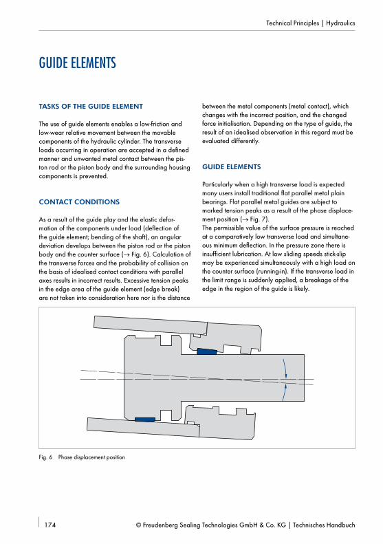
The use of guide elements enables a low-friction and low-wear relative movement between the movable components of the hydraulic cylinder. The transverse loads occurring in operation are accepted in a defined manner and unwanted metal contact between the pis-ton rod or the piston body and the surrounding housing components is prevented.
CONTACT CONDITIONS
As a result of the guide play and the elastic defor-mation of the components under load (deflection of the guide element; bending of the shaft), an angular deviation develops between the piston rod or the piston body and the counter surface (→ Fig. 6). Calculation of the transverse forces and the probability of collision on the basis of idealised contact conditions with parallel axes results in incorrect results. Excessive tension peaks in the edge area of the guide element (edge break) are not taken into consideration here nor is the distance
between the metal components (metal contact), which changes with the incorrect position, and the changed force initialisation. Depending on the type of guide, the result of an idealised observation in this regard must be evaluated differently.
GUIDE ELEMENTS
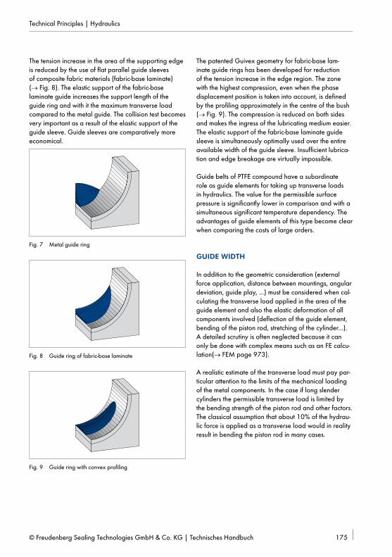
Particularly when a high transverse load is expected many users install traditional flat parallel metal plain bearings. Flat parallel metal guides are subject to marked tension peaks as a result of the phase displace-ment position (→ Fig. 7). The permissible value of the surface pressure is reached at a comparatively low transverse load and simultane-ous minimum deflection. In the pressure zone there is insufficient lubrication. At low sliding speeds stick-slip may be experienced simultaneously with a high load on the counter surface (running-in). If the transverse load in the limit range is suddenly applied, a breakage of the edge in the region of the guide is likely.
The tension increase in the area of the supporting edge is reduced by the use of flat parallel guide sleeves of composite fabric materials (fabric-base laminate) (→ Fig. 8). The elastic support of the fabric-base laminate guide increases the support length of the guide ring and with it the maximum transverse load compared to the metal guide. The collision test becomes very important as a result of the elastic support of the guide sleeve. Guide sleeves are comparatively more economical.
Fig. 7 Metal guide ring
Fig. 8 Guide ring of fabric-base laminate
Fig. 9 Guide ring with convex profiling
The patented Guivex geometry for fabric-base lam-inate guide rings has been developed for reduction of the tension increase in the edge region. The zone with the highest compression, even when the phase displacement position is taken into account, is defined by the profiling approximately in the centre of the bush (→ Fig. 9). The compression is reduced on both sides and makes the ingress of the lubricating medium easier. The elastic support of the fabric-base laminate guide sleeve is simultaneously optimally used over the entire available width of the guide sleeve. Insufficient lubrica-tion and edge breakage are virtually impossible.
Guide belts of PTFE compound have a subordinate role as guide elements for taking up transverse loads in hydraulics. The value for the permissible surface pressure is significantly lower in comparison and with a simultaneous significant temperature dependency. The advantages of guide elements of this type become clear when comparing the costs of large orders.
GUIDE WIDTH
In addition to the geometric consideration (external force application, distance between mountings, angular deviation, guide play, ...) must be considered when cal-culating the transverse load applied in the area of the guide element and also the elastic deformation of all components involved (deflection of the guide element, bending of the piston rod, stretching of the cylinder...). A detailed scrutiny is often neglected because it can only be done with complex means such as an FE calcu-lation(→ FEM page 973).
A realistic estimate of the transverse load must pay par-ticular attention to the limits of the mechanical loading of the metal components. In the case if long slender cylinders the permissible transverse load is limited by the bending strength of the piston rod and other factors. The classical assumption that about 10% of the hydrau-lic force is applied as a transverse load would in reality result in bending the piston rod in many cases.
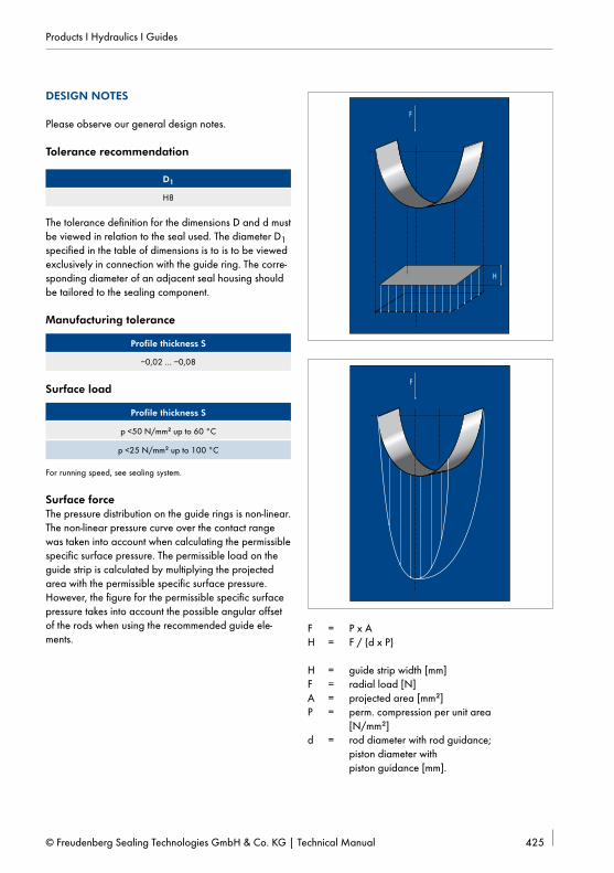
If the magnitude of the normal force applied in the area of the guide element is defined, the minimum required guide width (H) can be specified (→ Fig. 10).
F F
H
F = P x A; A = d x H; H = F / (d x P)H = guide strip width [mm]F = transverse load [N]A = projected area [mm2]P = permissible surface pressure [N/mm2]d = nominal diameter of rod or piston [mm]
Fig. 10 Guide width
The permissible specific surface pressure in the specified form is a manageable calculation value with reference to the projected area and does not represent the ma-terial characteristics. In the definition of the permissible specific surface pressure the non-linear pressure curve over the contact range, the tension increase in the edge area of the guide rings and a phase displacement posi-tion are all considered. When considering the specified values of the permissible specific surface pressure (P) of the guide sleeve it must be noted in comparison that some manufacturers include extra safety factors in some cases. However, that does not bring any increase in safety into the result of the calculation, because this fac-tor is returned to the associated equation.
H1̀
H1 H2
H2`
y
m
Fig. 11 Usable guide width
Metallic contacts between housing components and the counter surface are unwanted. The maximum permis-sible deflection (y) of the guide ring is limited by the smallest metal gap inside the sealing system, in general the metal step behind the primary seal.
Depending on the phase displacement position (α) of the piston rod and the possible deflection (y) with refer-ence to all influencing quantities, the usable guide width is reduced compared to the geometrically total width of the guide belts (H). Only the guide width actually in contact (H’) contributes to holding the load.
Fig. 12 Bilateral contact
In the case of large phase displacement positions, such as occur in relation to the compliance with long-slen-der cylinders, the guide ring may contact the counter surface on both sides of the centre axis. Here low toler-ance levels favour contact on both sides. The additional contact generates a usable counteracting force but also stick-slip effects (jamming) as a result of distortion. In this case the collision check has particular significance. To select the optimum width of the guide the desired serv-ice life must also be considered. Limit values are taken into account in the calculation of the minimum required guide width and also with reference to the permissible surface pressure of the guide elements. Guide elements
that are primarily traversed in the range of the maxi-mum possible load have a service life in the lower part of the range. Whether reducing the load by selecting a wider guide is useful in some cases depends on the previously considered safety factors as well as the total loading.
SPECIFIC COMPRESSION PER UNIT AREA
The permissible surface pressure (dynamic) is specified at a value in the range of 17 to 25 N/mm² for the copper-tin and copper-tin-lead bronze and high-load resistant copper-zinc alloys used in the area of the metal plain bearings. High-tensile alloys with values over 25 N/mm² are only used for the edge load of non-critical applications in connection with high-tensile counter surfaces.
Guide rings of fabric-laminated materials (fabric-base laminate) have improved function compared to straight metal guides. As a result of the low tension increase in the edge area and the elastic properties of these materi-als a higher surface pressure can be accepted. The val-ue of the surface pressure and the characteristics under
higher operating temperatures is greatly influenced by the composition of the fabric-based laminated material. Polyester and other plastics and also natural materials such as cotton are used in the area of fine fabrics. Pol-yester, vinyl ester and phenolic resin and also a whole range of plastics with different properties are available for the resin matrix. While some of these compounds show significant thermoplastic characteristics, the factor of the operating temperature on the permissible surface pressure is low for others.
The values for the permissible specific surface pressure depending on the operating temperature can be found in the tables in the description of the article.Under load guide elements show a deformation in the elastic range (reversible). The magnitude of the de- formation or deflection (y) is determined directly by the material characteristics, the thickness of the guide sleeve and the magnitude of the load. Assuming similar material characteristics, thicker guide sleeves have soft-er springing under identical loading. Pressure can only be applied to the guide element at the magnitude of the permissible surface pressure if the associated deflection of the guide element (→ Fig. 13) can be achieved with-out metal contact.
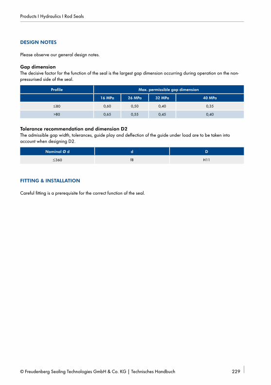
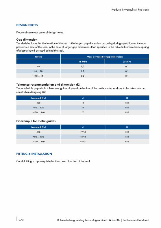
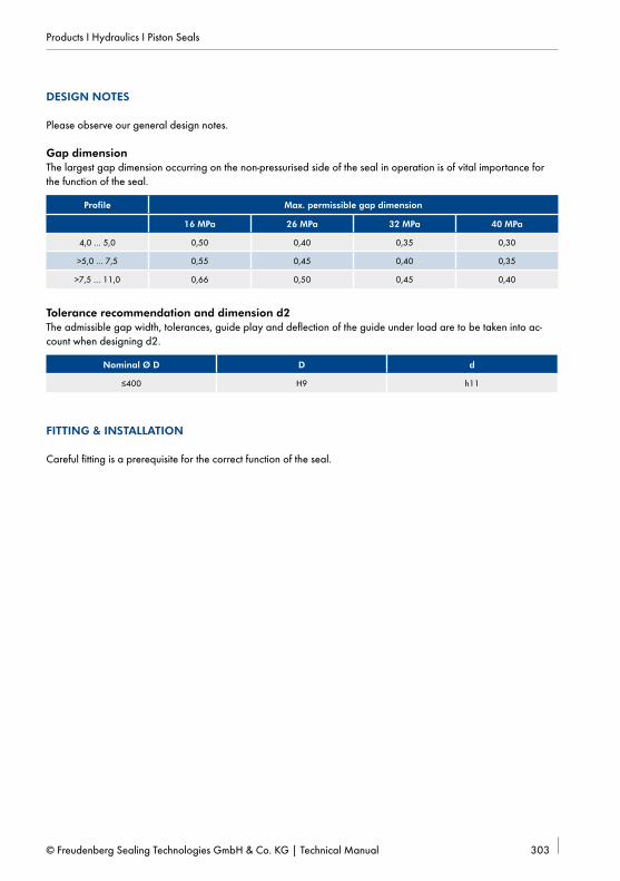
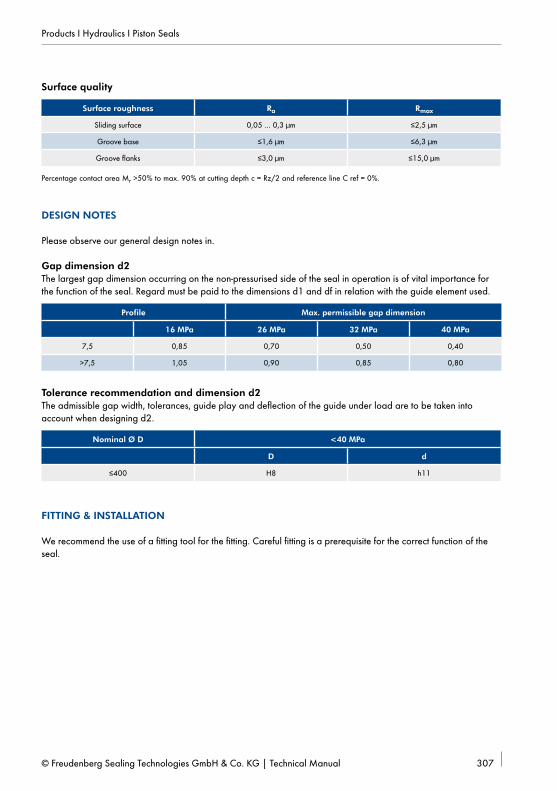
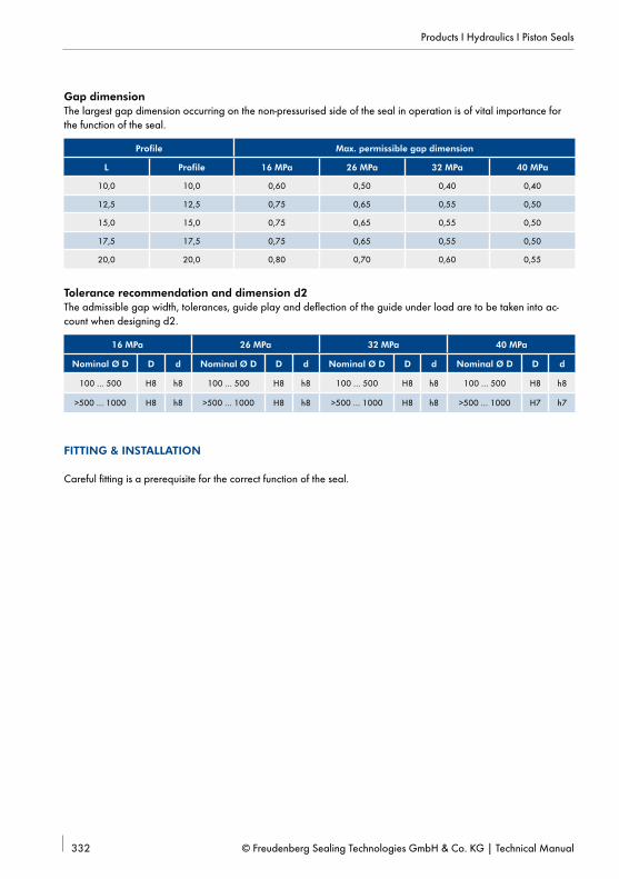
In a sealing system the collision check is generally con-ducted with reference to the metal gap on the side of the primary seal away from the pressure. The minimum permissible magnitude of the sealing gap is determined by the deflection of the guide element. The maximum permissible magnitude of the sealing gap is deter-mined by the form stability of the sealing component. General specifications for the maximum admissible gap width depending on the type of seal, the selected seal profile and the operating pressure can be found
in the tables in the description of the article. There is a direct geometrical dependency between the minimum required metal gap (x3) and the maximum permissible extrusion gap (x2) (→ Fig. 14). The gap dimensions can therefore not be calculated independently of each other. As a result guide elements cannot be subjected to the maximum permissible surface pressure at every pressure stage and with all types of seals, because the minimum required metal gap is not sufficient for com-plete deflection.
GeneralHydraulic drives are used in many machines and systems because of their varied options for use. Major areas of application are:
• Machines and systems engineering• Construction machinery• Agricultural machinery and• Mining machinery.
The most important component for generating the linear drive movement is the hydraulic cylinder. The function and reliability of hydraulically driven machines depends greatly on the seals installed in the hydraulic cylinder.
Static tightnessAt rest all elastic hydraulic seals are tight because of the excessive initial compression pv. The sealing pressure p is superimposed on the initial compression pv. The compression in the sealing area pd is therefore always greater than the sealing pressure (→ Fig. 15).
[1] pd = pv + p
Formation of the lubrication filmUnder movement the sliding surface coated with fluid is pulled under the contact area of the seal. The seal acts as a wiper, but is not able to wipe away the fluid completely.
The sliding movement causes a delayed flow and the seal is lifted from the sliding surface by the hydrody-namic pressure build-up. A thin film of fluid remains on the sliding surface behind the seal.
The thickness h of the following fluid film depends on the maximum pitch of the compression curve (dp/dx)
max on the entry side of the fluid in the sealing gap, the dynamic viscosity η of the fluid and the relative speed v between the seal and the sliding surface.
[2] h ~ √_______
η ⋅ v ______
( dp __ dx ) max
If the fluid film is completely returned to the pressure space on the return stroke, this is referred to as dynamic tightness.
FrictionThe friction of hydraulic seals is primarily influenced by the thickness of the lubricating film between the seal and sliding surface.
Three friction states may be encountered.
• Static friction (dry solid-body friction)
• Dry-fluid friction (solid-body friction and fluid friction)
• Fluid friction (no solid-body contact).
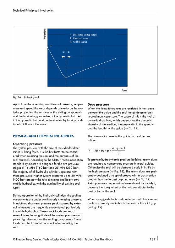
The three areas can be shown in the Stribeck graph (→ Fig. 16).
The high static friction must be overcome first during approach. With increasing speed more fluid is pulled between the seal and the sliding surface and the direct contact area decreases. Then the static friction initially decreases markedly.
The range of fluid friction is reached as the speed con-tinues to increase. The static friction increases again as the speed increases. The static friction is caused exclu-sively by the shear stresses τ in the fluid in the range of hydrodynamic lubrication.
[3] τ = η ⋅ dv ___ dh
WearThe wear on hydraulic seals depends on the thickness of the lubricating film or the friction status.Most seals operate in the region of dry-fluid friction and are subject to continuous wear.
Static friction (start-up friction)Mixed friction areaFluid friction area
Fig. 16 Stribeck graph
Apart from the operating conditions of pressure, temper-ature and speed the wear depends primarily on the ma-terial properties, the surfaces of the sliding components and the lubricating properties of the hydraulic fluid. Air in the hydraulic fluid and contamination by foreign bod-ies also influence the wear.
PHYSICAL AND CHEMICAL INFLUENCES
Operating pressureThe system pressure with the size of the cylinder deter-mines its lifting force. It is the first factor to be consid-ered when selecting the seal and the hardness of the seal material. According to the CETOP recommendation standard cylinders are designed for the two pressure stages of 16 MPa (160 bar) and 25 MPa (250 bar). The majority of all hydraulic cylinders operates with these pressures. Higher system pressures up to 40 MPa (400 bar) are now the rule in mining and heavy-duty mobile hydraulics. with the availability of existing seal types.
During operation of the hydraulic cylinders the sealing components are under continuously changing pressure. In addition, short-term pressure peaks caused by exter-nal influences are frequently encountered, particularly in mobile hydraulics. These shock loads can reach several times the magnitude of the system pressure and place high demands on the sealing components. These loads must be taken into account when selecting the seal.
Drag pressureWhen the fitting tolerances are restricted in the space between the guide and the seal the guide generates hydrodynamic pressure. The cause of this is the hydro-dynamic drag flow, which depends on the dynamic viscosity of the medium, the gap width hs the speed v and the length I of the guide (→ Fig. 17).
The pressure increase in the guide is calculated as follows
[4] ∆p = p1 – p = 6 ⋅ η ⋅ v ⋅ l
_________ h
2 s
To prevent hydrodynamic pressure build-up, return ducts are required to compensate pressure in metal guides. Otherwise the seal will be destroyed early in its life by the high pressure (→ Fig. 18). The return ducts are pref-erably designed as a spiral groove with a cross-section greater than the largest gap ring area (→ Fig. 19).Axial pressure compensation holes should be avoided, because the spray effect of the fluid contributes to the destruction of the seal.
When using guide belts and guide rings of plastic return ducts are already available in the form of the joint gap (→ Fig. 19).
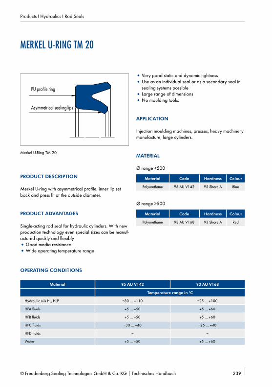
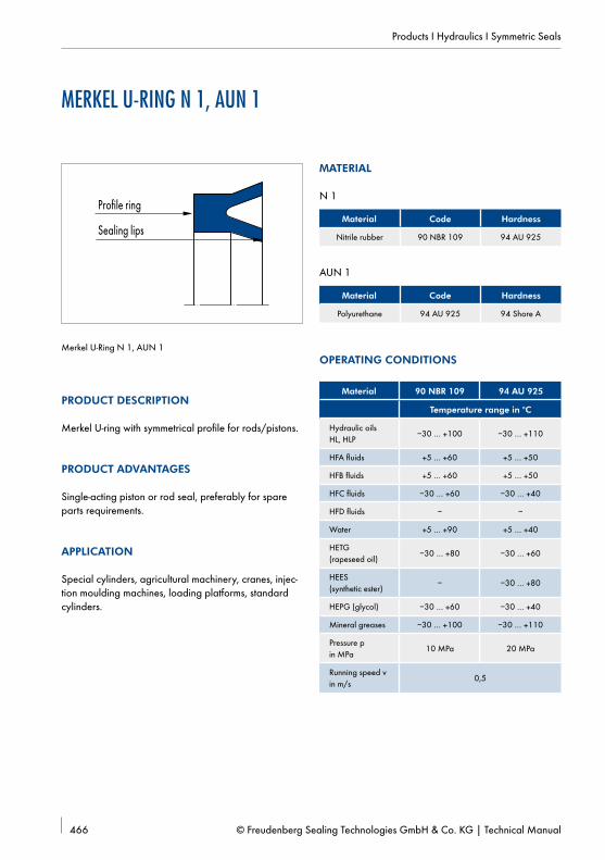
SpeedThe speed between the seal and the moving counter surface for rubber and polyurethane materials is normally 0,1 m/s to 0,5 m/s. However, the deciding factor is the application. For example, 0,8 m/s can be approved for the Merkel U-Ring T 20 as secondary seal and the same for the Merkel Compact Seal Simko 300 at a pressure of 250 bar. Up to 5 m/s is permissible for PTFE materials.
Fig. 18 U-ring destroyed by hydrodynamic pressure build-up
Fig. 19 Design measures for preventing drag pressure
The formation of a lubricant film and friction depend on the speed to a large degree. The friction force decreases greatly in the range of 0,05 m/s and lower. Particularly at high temperatures stick slip may occur. This juddering motion is a continuous repetition of stick and slip between seal and counter surface.Materials with lower coefficients of friction are used to prevent this (e.g. PTFE).
TemperatureThe temperature of the hydraulic medium and the am-bient temperature influence the material configuration. The optimum temperature for the function of the seals and the stability of the oil is +40 °C to +50 °C. The temperature at the sealing lip is significantly higher than the oil temperature because of the friction. The usual temperature during operation of the hydraulic cylinder is +80 °C, in extreme cases it may be up to 110 °C.
With increasing temperature the seal material becomes more elastic and loses form stability. For this reason we recommend running-in seals at lower temperatures (80 °C) if the temperature limit of 110 °C will be com-mon for our polyurethane materials. If temperatures over 110 °C are expected, it will be necessary to use special materials (e.g. FKM, PTFE/FKM). At lower temperatures the hardness of the seal materials will be increased. The seal will lose elasticity. However, the simultaneous increase in oil viscosity will leave the functional reliability of the seals virtually uninfluenced. In the temperature range down to –40 °C cold-resistant materials based on NBR have proven reliable. As previously noted, the temperature has a great influence on the physical properties of elastic rubber materials.The "torsion vibration test" graph (→ Fig. 20) shows how the dynamic thrust module G depends on the temperature (thrust module measured in the torsion vibration test according to DIN 53 520). The elastic rubber range with a virtually constant module can be recognised from right to left, then a steep rise to the
transition range and finally the glass state region, in which the rubber is hard and brittle, with a virtually constant module.When the temperature rises again the cold brittleness disappears again. This means that the freezing process is reversible. The transition from elastic rubber to the glass state region is particularly important is particularly important because in many cases it represents the limit of operation at low temperatures. This transition is not sudden but extends over a specific region, as shown in the "torsion vibration test" graph.
The region of transition from the elastic rubber region to the glass state is characterised by the glass transi-tion temperature Tü (temperature of the maximum of the logarithmic damping decrement Λ). However, this value can only represent a general dimension for the low-temperature operation limit of the material, because in practical application of an elastomer component it depends completely on the type of load involved.
The same material will reach its load limit at a higher temperature under shock load than, for example, with slow elongation. The torsion vibration test can be used to distinguish among different materials, but in practice the temperature limit must be tested in operation with the various components.
Example:
Friction resulting from movements generates heat in the case of contact seals. At temperatures at which there is a danger of hardening by freezing the frictional heat may be sufficient to maintain the elasticity of the seal or to place it in a functional condition sufficiently quickly after the movement has started. The behaviour under cold conditions is therefore only ever worth testing in the form of a material comparison in connection with experience of the technical application.
For further information → General technical data and materials from page 897.
Hydraulic mediaIn hydraulics various hydraulic fluids are used to trans-mit the energy from the pump to the cylinder. The most important and most frequently used Die hydraulic fluid is mineral oil.
The lubricating capacity of the oil is decisive for the wear of the moving parts. The lubricating capacity is influenced by the viscosity and additives that improve the lubrication.
Hydraulic oils are classified in viscosity classes in ac-cordance with DIN ISO 51519 to identify the viscosity. The criterion for the categorisation is the nominal viscos-ity at the reference temperature of +40 °C.
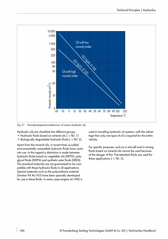
The viscosity of hydraulic oils depends on the pressure and the temperature. The viscosity increases significant-ly from a pressure of about 20 MPa (200 bar). The viscosity doubles at approximately 40 MPa (400 bar) depending on the nominal viscosity and the tempera-ture. Under an increasing temperature the viscosity of oils decreases very rapidly. The characteristic value for this viscosity-temperature behaviour is the viscosity index (VI). The higher the viscosity index of a hydraulic oil the less the viscosity depends on the temperature (→ Fig. 21).
Fig. 21 Viscosity-temperature behaviour of various hydraulic oils
Hydraulic oils are classified into different groups:• Hydraulic fluids based on mineral oils (→ Tbl. 1)• Biologically degradable hydraulic fluids (→ Tbl. 2).
Apart from the mineral oils, in recent times so-called environmentally compatible hydraulic fluids have come into use. In this regard a distinction is made between hydraulic fluids based on vegetable oils (HETG), poly-glycol fluids (HEPG) and synthetic ester fluids (HEES). The standard materials are not guaranteed to be com-patible with these hydraulic fluids in all applications. Special materials such as the polyurethane material Simritan 94 AU 955 have been specially developed for use in these fluids. In some cases engine oil /HD) is
used in travelling hydraulic oil systems, with the advan-tage that only one type of oil is required for the entire vehicle.
For specific purposes, such as in aircraft and in mining, fluids based on mineral oils cannot be used because of the danger of fire. Fire-retardant fluids are used for these applications (→ Tbl. 3).
H HH Mineral oil without active additives is virtually never used today
H-L HLcorrosion-prevention additives and additives for increasing ageing resistance
for lightly loaded systems
H-LP HMlike H-L, as well as wear-reducing additives and additives for increasing loading
for heavily loaded systems
H-LPD –like H-LP, as well as detergent and dispersive additives
for heavily loaded systems when there is danger of water ingress dur-ing oil filling
H-V HVlike H-LP, as well as improved viscosity-temperature behaviour
systems that are used at low or very variable temperatures
Tbl. 1 Hydraulic fluids based in mineral oil
Classification in accordance with DIN proposal Base fluid
HEPG Polyglycol
HETG Vegetable oil
HEEG Fully synthetic ester
Tbl. 2 Biologically degradable hydraulic fluids
Group Composition/water contentApplication tem-perature range
Kinematic viscosity at +40 °C
Application
Hydraulic fluids containing water
HFA EEmulsions of mineral oil in water, water content >80% (generally 95%)
–+5 … +60 °C 0,5 … 2 mm2/s
mining, hydraulic presses, hydrostatic drives with low operating pressures
HFA SSynthetic oil in aqueous solution, water content >80% (generally 95%)
HFBEmulsions of water in mineral oil, water content >40%
–+5 … +60 °C non-Newtonian fluidnot in use in Germany
HFCaqueous polymer solutions, water content >35%
–30 … +60 °C 20 … 70 mm2/sHydrostatic drives with low operating pressures
Non-aqueous hydraulic fluids
HFD R based on phosphoric acid ester
–30 … +150 °C 10 … 50 mm2/snot approved for use in German coal mines
HFD SBased on chlorinated hydrocarbons hydrodynamic couplings up to 150 °C
HFD T Mixtures of HFD R and HFD S
HFD USynthetic fluids of other composition approved
Tbl. 3 Fire-retardant fluids
Because of the large and somewhat confusing selection of media with different and varying additives, the above usage limits can only be consid-ered recommended values. We recommend testing for individual cases
VDMA Directive 24317 lists the properties and identifi-cation of these fluids. DIN 24320 specifies the properties of HFA fluids. Of the fire-retardant fluids it is primarily the HFA fluids that have become established in mining. HFB and HFD fluids are only used in exceptional cases.
Contamination in oil circulationHydraulic oils can be contaminated by foreign bodies such as sand, metal abrasion, metal shavings and oxidation products (ageing of the oil by the action of high temperatures and oxygen).If the oil is insufficiently filtered the seal the other components in the hydraulic system may not operate correctly. Metal shavings and abrasive grains of sand will cause failure of the seal as soon as these particles enter the area beneath the sealing edge.
Air in oilThere are dissolved air molecules in all classes of hy-draulic fluids. This air dissolved in the oil does not affect the function of the seal. Hydraulic oil can form a molec-ular bond to more as the pressure increases. Then when the pressure is reduced the dissolved air comes out of solution. Air bubbles form, which frequently collect in the groove spaces not filled by the seals.
If the pressure is suddenly increased, the air-oil mixture is heated so strongly that compression ignition may occur. This phenomenon, referred to as diesel effect, may destroy the seal if it occurs frequently. The seal may also be damaged by undissolved air during the movement.
The air bubbles dragged in with the oil between the seal and the counter surface expand more the closer they come to the non-pressurised side of the seal. This air-bubble erosion causes longitudinal scores in the sur-face of the seal. This results in further destruction of the seal by washing out and removal of surface areas by the flowing fluid (flow erosion).
The damage caused by air in the oil can be greatly re-duced if the complete hydraulic system is carefully bled before operation.
GEOMETRICAL INFLUENCES
StrokeThe stroke of the working cylinder is mostly between 0,1 m and 1,0 m. When the strokes are very short, only a few centimetres, and the load frequency is high, the required lubricating film will not be formed and seals of rubber materials may be subject to increased wear.
In such cases sealing components of PTFE are prefera-bly used. If the strokes are long, in the range of several metres, there is a danger that the sealing component will be excessively heated. Distortions of the shape of the rod, different surface roughness and eccentricity occur more frequently with long strokes.
HousingsThe following criteria are used to specify the housings and thus the dimensions of the seal:
• Use and load type of cylinder• Standard seal or special seal• Standardised housings.
The greater the load on the seal the stronger the profile. With equivalent seal diameter seals of smaller radial thickness are more likely to be damaged and to wear. The same percentage radial oversize the absolute over-size (in millimetres) of a seal with a smaller radial thick-ness is less than a seal with larger radial thickness.A seal with a stronger profile is better able to bridge large eccentricities resulting from the guide play.
The dimensions listed in the catalogue are available immediately from stocks or are articles that can be de-livered at short notice, which have been used success-fully for years for sealing pistons and piston rods. The dimensions are marked accordingly when they match the dimensions specified by the standard.
The housings for rod and piston seals are specified in DIN ISO 5597.DIN ISO 6547 contains the housings for piston seals with integrated guide elements.DIN ISO 6195 governs the housing for wipers.ISO Standard 7425 specifies compact seals, consisting of one slip ring of PTFE and an elastic compression ring.
The sealing gap is defined as the gap bordered by the counter surface and the housing on the pressurised side of the seal. Because of the different general conditions
Ød ØDFØD2
Sx3
x2 xf
Fig. 22 Limit values of sealing gap of rod sealing system
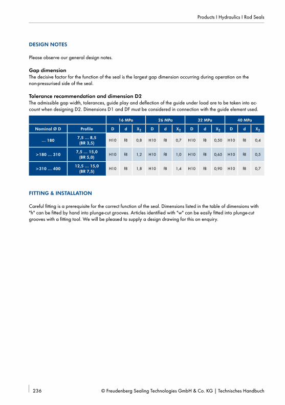
LIMIT VALUES
When considering the limit values with reference to the sealing gap the maximum adjustable sealing gap (x2) and the minimum sealing gap (x3) with one-sided
mount of the piston rod or the piston body are taken into account (→ Fig. 22 and Fig. 23).
ØdF ØDØd2
x2xf
x3
S
Fig. 23 Limit values of sealing gap of piston sealing system
x2 = (D2max – dmin) / 2 + xfmax / 2
x3 = (D2 – [DFmax – (2* Smin)]) /2
xfmax = [DFmax – (2* Smin)] – dmin
D2max = dmin + 2 x 2 - xfmax
d = shaft [mm]
DF = groove base of guide [mm]
D2 = non-pressurised side [mm]
S = thickness guide sleeves [mm]
x2 = maximum sealing gap [mm]
x3 = minimum sealing gap [mm]
xf = guide play [mm]
x2 = (D2max – d2min) / 2 + xfmax / 2
x3 = ([dFmin + (2* Smin)] – d2max) /2
xfmax = Dmax – [dFmin + (2* Smin)]
d2min = D2max + xfmax - 2 x 2max
d = bore [mm]
DF = groove base of guide [mm]
D2 = non-pressurised side [mm]
S = thickness guide sleeves [mm]
x2 = maximum sealing gap [mm]
x3 = minimum sealing gap [mm]
xf = guide play [mm]
the primary and secondary seals of a sealing system considered separately with reference to the sealing gap.
The maximum sealing gap (x2) should be as small as possible (gap extrusion), the minimum sealing gap (x3) should be as large as possible (metal contact). Because there is a direct geometrical dependency between the minimum required metal gap (x3) and the maximum permissible extrusion gap (x2), the gap dimensions can-not be set independently of each other.
GAP EXTRUSION
Seal materials act like a viscous fluid under the influ-ence of the operating pressure. When the pressure is applied the sealing component is pressed closer to the metal housing and to the sealing gap. The ingress of the seal material into the sealing gap is referred to as the gap extrusion. The sealing component is damaged in the area of the metal edge of the installation space by the ingress of the seal material into the sealing gap. The repeated damage eventually causes failure of the sealing component.
When specifying the maximum gap dimension (x2) the temperature, material and geometry-dependent form stability of the sealing component and the operating and general conditions must be considered. In addition to the clear connection between the form stability of a sealing component and the operating pressure or the operating temperature, the limit values for the sealing gap are determined by the total loading, as well as other things. The pressure applied with simultaneous relative stroke movement in the direction of the extrusion gap is more demanding than a static or quasi-static seal with refer-ence to the power consumed by friction and shearing forces in the contact zone. A short pressure pulse is uncritical with reference to the gap extrusion, but an extended application of pressure places increased demands on the long-term form stability of the sealing component (flow).
The relevant enlargement of the sealing gap as a result of the cylinder stretching (cylinder barrel) or cylinder buckling (hollow rods) must be considered, particularly with higher operating pressures or light design. The deflection of the guide element must also be considered borderline designs with high transverse loads.
General figures for the maximum admissible gap width (x2) are listed in the tables with the article description depending on the type of seal, the selected seal profile and the operating pressure.
METAL CONTACT
When specifying the minimum gap dimension (x3), the collision control is particularly important. The narrowest sealing gap in a sealing system is normally behind the primary seal. Collision control is therefore run primarily for this area. Where the design requires large gaps between the sealing components and also large angu-lar deviations the collision control should be extended appropriately.
Marginal designs with high transverse loads and long slender cylinders must also be protected with reference to bending of the piston rod and the deflection of the guide element. Cylinders with short support length are tested for the required angular error.
Metal contacts between the counter surface and the in-stallation space components cause comparatively high costs when service is required. Within the permissible limits and with reference to the operating and general conditions the dimensions and tolerances are selected to yield as large a value as possible for the sealing gap x3 and thus the greatest possible security against metal contacts. The minimum required value for x3 is determined primarily by the deflection of the guide element under load (see additional information on guide elements).
Both sides are subject to wear at the contact and during simultaneous relative movement between the sealing components and the counter surface. To establish a stable sealing effect over the long term, the changes caused by the contact must be minor. After a short run-ning period during which the sealing edge must not be damaged by abrasive wear, stable running character-istics must established. The system consisting of sealing components, counter surface and lubricating film must be optimised for sealing effect, friction behaviour and wear. The geometry, the material of the sealing compo-nents, the topography, the material of counter surface and the properties of the hydraulic medium all influence the operation of the system.The factor of individual parameters on the overall sys-tem is strongly dependent on the operating conditions. While the solid-body friction is the primary factor with a low stroke speed and high operating pressure, with a high stroke speed and low operating pressure a hydro-dynamic lubricating film may be built up. The influence quantities are always mutually interdependent. In an optimally set up system a thin lubricating film is released outside beneath the sealing components. The oil film must be transported completely back to the hydraulic system at every cycle. Inside sealing systems all indi-vidual seals and the wiper must meet this condition.
Fig. 24 Non-wettable surface
An absolutely sealing component that does not release a lubricating film outside is as unsuitable as an absolutely smooth counter surface (→ Fig. 24) in which there are no abrasive components and also no lubricant pockets when considering the dependencies described above. In both cases a very unfavourable friction and wear behaviour will be established.
SURFACE STRUCTURE
The structure of the counter surface is primarily influ-enced by the machining process used for finishing. With reference to retaining the lubricating film it is better to generate chaotic surface structures. Dynamic effects are generated on aligned structures and in relation to the stroke movement in the area around the sealing edge. The applied lubricating film can be enlarged here and is visible as leakage. A surface generated by turning and grinding or honing cannot be accurately described geometrically. In turning the material is not sheared at the theoretical contour line, because during processing material particles are also pulled out from a depth. Geometrically undetermined cutters indentations and heights are also formed by grinding and honing (→ Fig. 25). A surface with formation of fine burrs is generated.
Whether such a surface is suitable for use in contact with the sealing components cannot be sufficiently derived from the currently used surface parameters Ra, Rmax and Mr. Depending on the general manufacturing conditions both abrasive and non-abrasive counter sur-faces are created within the limit values. Processes that remove material for final machining are only suitable if the process can be managed. This requires a measured value for the abrasiveness.
When manufacturing processes for final machining are used in which material is not removed (e.g. rolling) com-paratively smooth surfaces are generated, which do not normally have any abrasive components. Because it is difficult to wet a smooth surface, it is more difficult to form a lubricating film. However, such surfaces are generally suitable for a counter surface in contact with sealing components.
HARDNESS/COATING
The counter surface and the sealing and guide elements are in contact as a result of relative movement (friction) and compression (transverse load; operating pressure). The required hardness of the counter surface depends on the height and type of loading. Slow movements with high surface load (deformation of the counter surface) and rotary movements (running-in as a result of wear) are the most demanding.
The hardness of the surface generates sufficiently wear-resistant and stable edge coatings. However, the thickness of the edge coating and the quality of the base material are very important. If it is too soft, a comparatively thin edge coating will be deformed or broken with deflection of the base material. This effect can be observed particularly with hard chrome coat-ings on soft substrate material. The highest compression depends on the transverse load and the operating pres-sure in the region of the guide element or the primary sealing component. With complete deflection of an HGW guide ring and a correspondingly high transverse load maximum compressions of pmax~110N/mm² are reached. In the case of the sealing components the pressure distribution depends on the geometry of the sealing edge (→ Fig. 26). An operating pressure of 30 MPa a maximum compression of pmax~50N/mm² can be expected for the Merkel Omegat OMS-MR Rod Seal.
PCompression = Pressure
Fig. 26 Qualitative compression curve, single-acting rod seal
In the area of rod sealing systems base steel of quality Ck45N with a surface hardness of 55-60 HRC is used for cylinders under high loading. In general high-alloy, stainless steels based on CrMo or CrMoNi have proven reliable.
Piston sealing systems are under less load compared to rod sealing systems with reference to the compression curve (no pronounced sealing edge) and the lubrica-tion. The counter surface in cylinder bores are not nor-mally hardened. Under high loading high-alloy, stain-less steels based on CrMo or CrMoNi (e.g. 42 CrMo4 + QT or 42 CrMo4V and 36 NiCrMo T + TQ) have proven reliable.
Nitrated counter surfacesNitration saturates the edge coating of the workpiece with nitrogen by diffusion. The result is a hard, wear-re-sistant and corrosion-resistant compound layer (thick-ness 10-20 µm). The hardness diminishes with increas-ing depth (diffusion coat). Depending on the process and the basic material a total penetration depth of up to 1 mm is reached. In salt-bath nitration (in a weaker form also with gas nitration) a large number of deep pores is formed in the outer compound layer. Even un-der a minor load (abrasive) particles tend to break out of the porous compound layer.
A surface of this type cannot be used in contact with the sealing components without additional mechanical processing. Nitrated counter surfaces can be used in sealing technology without problems when they have been appropriately processed.
Chromed counter surfacesPolished hard chrome layers (thickness 30-50 µm) do not generally have any abrasive component and, assuming a sufficiently hard substrate, are suitable for use as a counter surface in contact with the sealing components. Matt chroming forms microscopically small sharp tips, which cause heavy wear. Such surfaces must be mechanically processed before use in every case.
Ceramic and partially ceramic counter surfacesWhen using ceramic and partially ceramic surface (total thickness 300 µm) corrosion protection (saltwater resistance) and wear resistance are the primary purpose.
Ceramic counter surfaces are not smoothed in contact with the sealing components. The contact with the permanently sharp-edged crystal structure causes high wear on the sealing components. Sealing systems for ceramic counter surfaces are designed with adapted seal materials and special seal layouts and as such have a special position.
Fig. 28 Ceramic surface
In general brittle coatings would break with the elongation of the cylinder bores when pressure is applied. Therefore, in hydraulic cylinders only piston rods are coated.
DESCRIPTION OF COUNTER SURFACE MEAS-URABLE IN THE LABORATORY
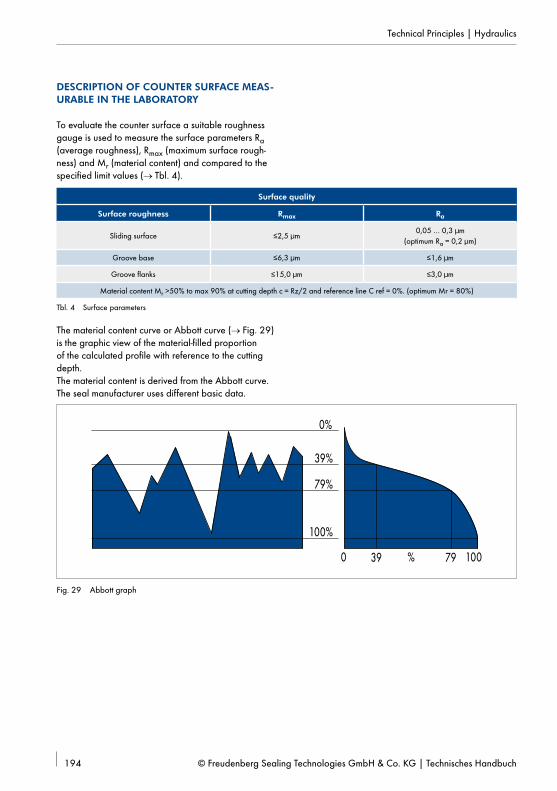
To evaluate the counter surface a suitable roughness gauge is used to measure the surface parameters Ra (average roughness), Rmax (maximum surface rough-ness) and Mr (material content) and compared to the specified limit values (→ Tbl. 4).
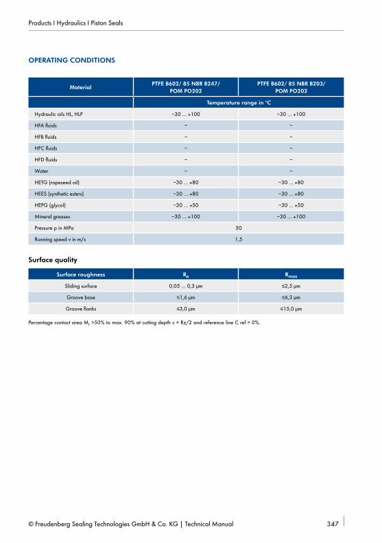
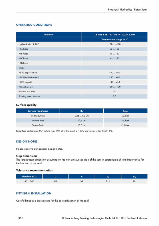
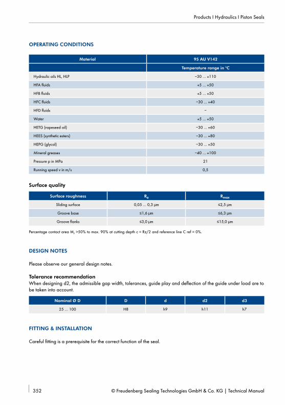
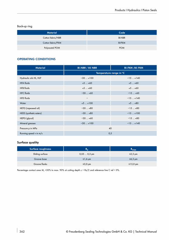
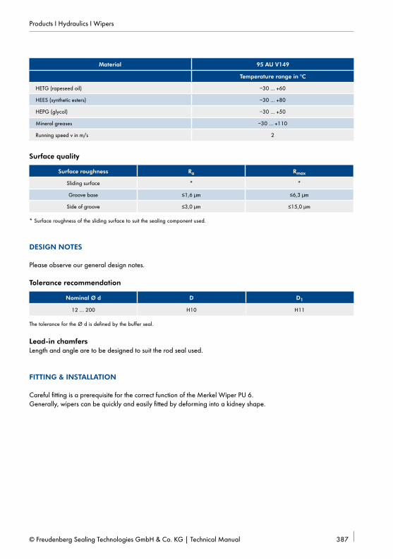
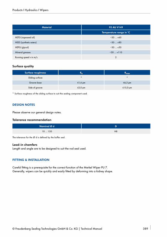
Surface quality
Surface roughness Rmax Ra
Sliding surface ≤2,5 µm0,05 … 0,3 µm
(optimum Ra = 0,2 µm)
Groove base ≤6,3 µm ≤1,6 µm
Groove flanks ≤15,0 µm ≤3,0 µm
Material content Mr >50% to max 90% at cutting depth c = Rz/2 and reference line C ref = 0%. (optimum Mr = 80%)
Tbl. 4 Surface parameters
The material content curve or Abbott curve (→ Fig. 29) is the graphic view of the material-filled proportion of the calculated profile with reference to the cutting depth.The material content is derived from the Abbott curve. The seal manufacturer uses different basic data.
In the case of FST the entire surface including the full peak height relevant to the abrasivity and possible damage at first contact is considered starting from a ref-erence line at Cref = 0% (→ Fig. 30). It remains uncon-sidered with a reference line Cref = 5% (→ Fig. 31).
Parameters such as Ra, Rmax, Rz and the material con-tent Mr have become established. The behaviour of the counter surface compared to the sealing components cannot yet be described with sufficient accuracy with reference to the abrasivity.
EXTENDED LABORATORY DESCRIPTION OF THE COUNTER SURFACE
The service life of the sealing component in a sealing system is determined by the contact between the coun-ter surface and the sealing component. The contact influences by the comparatively soft sealing component (wear) and the hard counter surface (smoothing). If the sealing edge is damaged as a result of abrasive wear on the first strokes of the hydraulic cylinder, the sealing effect and the service life will be reduced accordingly. An extended laboratory examination of the counter sur-face is urgently required to measure abrasivity to ensure stable running characteristics over the long term.
The description of the counter surface can be refined by evaluation of additional parameters of the Abbott curve (→ Fig. 32):
10 20 30 40 50 60 70 80 90 100
Rpkx
0
[mm]
Mr 1
Rk
Rpk
Mr 2
RvkRvkx
Mr [%]
Abbott curve
Rpkx, full peak height; abrasive component.
Rpk, reduced peak height; profile peaks.
Rk, core surface roughness; supporting core; the main function area
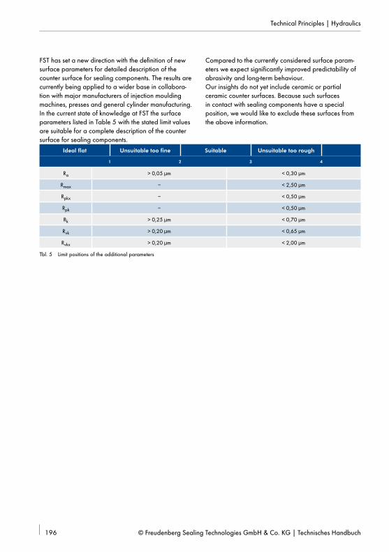
FST has set a new direction with the definition of new surface parameters for detailed description of the counter surface for sealing components. The results are currently being applied to a wider base in collabora-tion with major manufacturers of injection moulding machines, presses and general cylinder manufacturing.In the current state of knowledge at FST the surface parameters listed in Table 5 with the stated limit values are suitable for a complete description of the counter surface for sealing components.
Compared to the currently considered surface param-eters we expect significantly improved predictability of abrasivity and long-term behaviour.Our insights do not yet include ceramic or partial ceramic counter surfaces. Because such surfaces in contact with sealing components have a special position, we would like to exclude these surfaces from the above information.
Ideal flat Unsuitable too fine Suitable Unsuitable too rough
1 2 3 4
Ra > 0,05 µm < 0,30 µm
Rmax – < 2,50 µm
Rpkx – < 0,50 µm
Rpk – < 0,50 µm
Rk > 0,25 µm < 0,70 µm
Rvk > 0,20 µm < 0,65 µm
Rvkx > 0,20 µm < 2,00 µm
Tbl. 5 Limit positions of the additional parameters
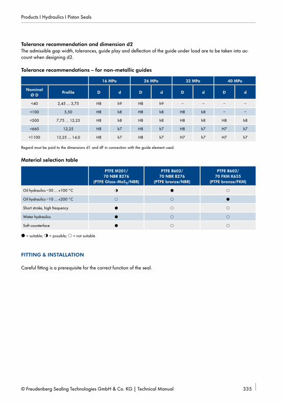
The function of a sealing component is influenced by the geometry and primarily by the seal material. The influence of the specific material properties on the function of the seal in this regard depends among other factors on the nature of the relative movement between the sealing component and the counter surface (stroke, rotation, static).
As well as the chemical resistance the form stability, friction behaviour and elastic behaviour are significant influence factors. Unwanted material influences are in part compensated by additional components such as back-up rings (extrusion resistance) or pre-load compo-nents (initial sealing effect). A function-oriented design of the seal always considers the sealing material in use. Not every geometry can be manufactured easily with every material.
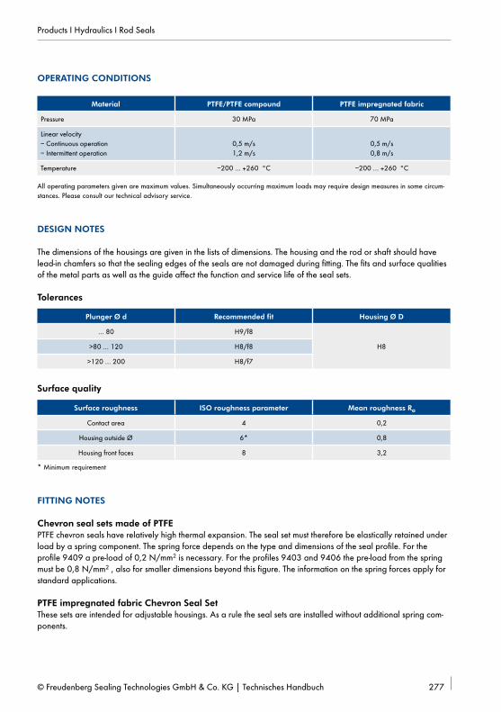
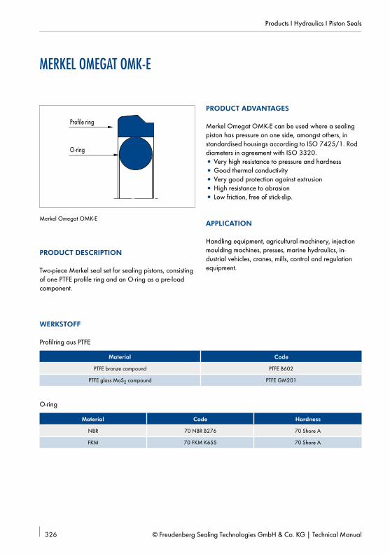
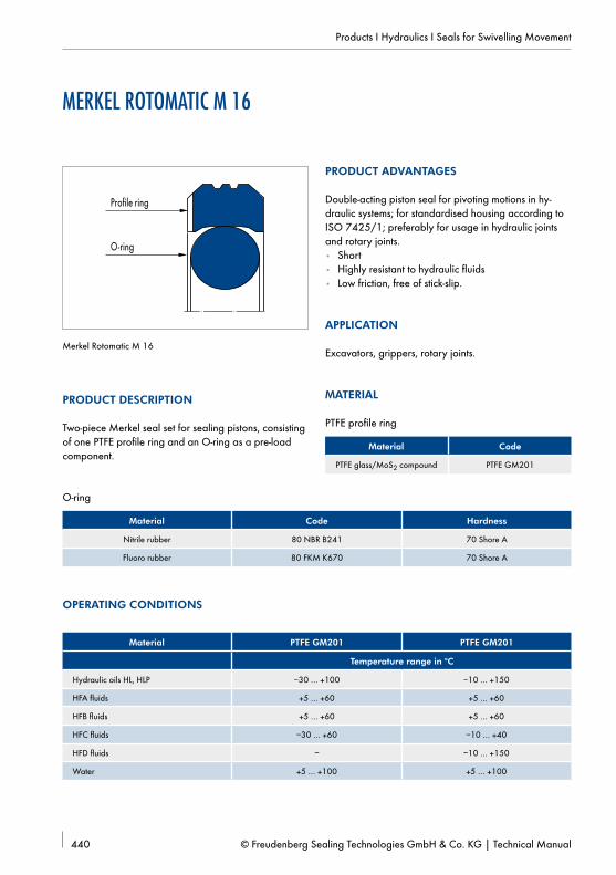
MATERIALS
In hydraulic applications multi-component sealing components with a sliding ring of PTFE compound and an elastomer pre-load component as well as single and multi-component sealing components of elastomer (NBR, FKM) or polyurethane are primarily used. For the guide elements fabric-base laminate compounds are mostly used.
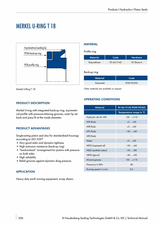
Back-up rings are manufactured of PTFE (polytetrafluo-roethylene), PA (polyamide) or POM (polyoxymethyl-ene) depending on the requirements. As well as these materials in some cases special materials such as PE (polyethylene), TPE (thermoplastic polyester-elastomer) and PEEK (polyetheretherketone) are used.
PTFE COMPOUND
Pure (virgin) PTFE has a comparatively low structure and friction strength. Even under a low load the materi-al is deformed and begins to flow (cold flow). The addi-tion of fillers (compounding) such as bronze, glass fibre and carbon fibre can significantly improve form stability and friction strength. Depending on the requirements other fillers such as carbon or graphite and also colour additives are also used.
PTFE is a horny, non-elastic material. The initial contact pressure of the PTFE sealing component to the counter surface required for the sealing function can only be applied by an additional contact pressure element (elastomer or spring) because of the missing elasticity. PTFE sealing components therefore always have multi-ple components.
Metal
Metal
PTFE compound
Polyurethane
Metal
Elastomer
Fig. 33 Sealing edge in contact with counter surface
PTFE compounds are noted for high pressure resistance and favourable friction behaviour. A friction value (oiled) between µ = 0,02 and µ = 0,1 can be expected depending on the contact conditions.
The structure of the PTFE material causes the sealing component to slide on the higher components of the surfaces (microstructure). The sealing edge does not en-ter the roughness valleys (→ Fig. 33). As a result of this behaviour PTFE sealing components allow a compara-tively thicker lubricating film beneath the sealing edge.
PTFE sealing components are preferably used as a primary seal in sealing systems or as a piston seal with bilateral pressure application.
Dirt adhering to the piston rod can be kept from enter-ing the hydraulic system with suitable design of the wip-ing edge when using wipers of PTFE compound.
When selecting the PTFE compound amongst others the following properties are assessed with reference to the actual application:
• The influence of the hydraulic medium• The behaviour in contact with the counter surface• The form stability depending on the operating
temperature.
PTFE bronze (PTFE B602) is the standard compound for general applications. In addition to its very smooth sliding properties the high form stability, even at high temperatures, as well as high wear resistance are par-ticularly important.
The metal bronze and its components are not chemi-cally neutral. In contact with water or water emulsion and in some cases also with additives in the hydraulic medium chemical reactions may be started.
The chemical reaction and also generally the results of insufficient lubrication can cause a typical damage pat-tern (fine strips) on the counter surface in contact with the sliding ring of a sealing component of PTFE bronze.
The restriction described is generally applicable for all PTFE bronze compounds available on the market. However, because of the compounding, which varies in detail, the results must be evaluated very differently.
If the lubrication is insufficient (poorly lubricating hy-draulic medium, short stroke, stroke at high load and low stroke speed), the use of PTFE glass fibre MoS2 (PTFE GM201) has proven to be suitable. Influence by standard hydraulic media is not a factor because the glass fibres are chemically neutral.
T = 80 °CT =120 °C
PTFE GM201(PTFE/Glass fibre MoS2)
PTFE B602(PTFE/Bronze)
PTFE C104(PTFE/Carbon fibre)
Competition(PTFE/carbon fibre)
Defor
matio
n
Fig. 34 Form stability of PTFE compounds in comparison
The pressure resistance of PTFE glass fibre is lower than that of PTFE bronze. In the temperature range above 100 °C there are significant differences in the form sta-bility in comparison with PTFE bronze (→ Fig. 34).
The positive properties of PTFE bronze and PTFE glass fibre are combined in the PTFE carbon fibre compound (PTFE C104). The compound has favourable behaviour with insufficient lubrication and comparatively high form stability.
The matrix of modified PTFE is the difference in com-pound PTFE C104 compared to other PTFE carbon fibre compounds. The cost of the base material and the processing are higher than for PTFE bronze, PTFE glass fibre and simple PTFE carbon fibre compounds. There-fore, this compound is generally used for applications where neither PTFE bronze nor PTFE glass fibre MoS2 appear suitable.
The maximum permissible operating pressure is prima-rily determined by the extrusion gap and the tempera-ture-dependent form stability of the seal material. Be-cause the size of the extrusion gap cannot be selected as very small with reference to metal contacts, the pres-sure application range of the sealing component must be limited depending on the temperature.
An operating pressure of up to 40 MPa is generally permissible in the average temperature range, depend-ing on the extrusion gap. At an operating temperature above 100 °C the operating pressure should remain limited to 26 MPa with the use of PTFE glass fibre and the simple PTFE carbon fibres.
The PTFE profile ring of a PTFE seal is machine-manufac-tured up to a nominal diameter of 2000 mm. It cannot be manufactured by injection moulding.
POLYURETHANE
Polyurethane has a high wear resistance and a compar-atively high form stability. With the elastic behaviour of the material sealing components can be designed as single-piece components, i.e. without an extra pre-load component. Polyurethane under pressure behaves as a viscous fluid. At an operating pressure above 10 MPa sealing components of polyurethane are completely formed. The full contact to the counter surface makes ingress of the lubricating medium in the contact area difficult and as a consequence increases the friction wear. The use of a sealing system should be preferred to the individual seal with reference to the achievable service life.
Code Colour
95 AU V142 dark-blue
94 AU 925 light-blue
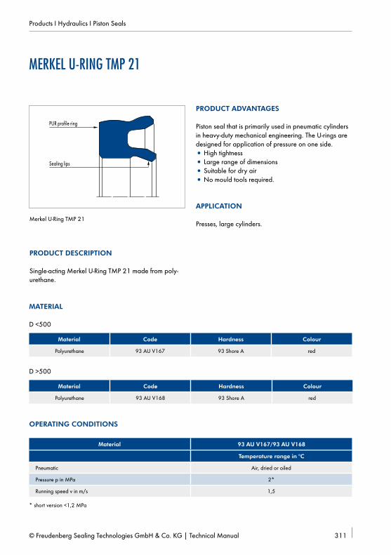
93 AU V167 light-red
93 AU V168 light-red
95 AU V149 dark-blue
AU V206 dark-yellow
AU V204 light-yellow
92 AU 21100 white
Tbl. 6 Overview of polyurethane
Sealing components of polyurethane wipe away the hydraulic medium reliably with suitable design of the sealing edge. Assuming adequate media resistance, seals of polyurethane are used as primary and secon-dary seals (gap pressure up to 5 MPa) inside sealing systems. Their use as individual seals in combination with a double wiper is also widespread. With its high wear resistance polyurethane is also very suitable as a material for wipers. Sealing components of polyure-thane can be manufactured by injection moulding or rotary processes to a nominal diameter of approximate-ly 2000 mm. The qualities of polyurethane used (→ Tbl. 6) can be processed more or less easily depending on the nominal diameter and the manufac turing process. On the other hand some qualities are noted for excellent properties such as increased resis tance to hydrolysis (hydrolysis = loss of structure as a result of contact with water) or improved properties in the low-temperature range.
Sealing, wiping and pre-load components of NBR (acrylonitrile-butadiene rubber) or FKM (fluoro elasto-mer) are primarily used in the area of hydraulic appli-cations. Depending on the general conditions HNBR (hydrogenated acrylonitrile-butadiene rubber) and EPDM (ethylene-propylene-diene rubber) are also used.
Sealing components of elastomer wipe away the hy-draulic medium and also fine dirt reliably with suitable design of the sealing edge. In this respect they are su-perior to PTFE and polyurethane. On the other hand the high sealing effect causes the elastomer to penetrate the microstructure of the counter surface (→ Fig. 36) and thus forms a very close contact between the sealing component and the counter surface. The friction and the wear are increased particularly when pressure is applied compared to PU and PTFE (→ Fig. 35).Sealing components of elastomer tend to adhere to the counter surface after extended downtime because of this property.
Because of the low resistance to gap extrusion (form stability) seals of elastomer without additional rein-forcement such as fabric inserts (Chevron seal sets) or back-up rings can only be used at low pressures up to 10 MPa.
Elastomer seals with fabric reinforcement are robust and with pressure applied have sufficient form stability. How-ever, such sealing components are often not sufficient to meet the increased demands related to stroke speed and service life, primarily because of the unsuitable Friction behaviour.Elastomers are mainly used as wipers and in the form of O-rings as static seals or pre-load components. Elastomers are only used as secondary seals in sealing systems if polyurethane cannot be used because of the media resistance or the operating temperature.
Fig. 36 Loading depending on the operating temperature
FABRIC-BASE LAMINATE
Fabric-base laminates consist of a fine fabric bonded with resin. Relevant properties such as the friction strength, the permissible surface load (acceptance of transverse loading) and the temperature dependency of the material behaviour are set depending on the properties of the components. Polyester and other plas-tics and also natural materials such as cotton are used for the fine fabric. In addition to polyester, vinyl ester and phenol resin a whole range of plastics with various properties are available for the resin matrix. While the friction resistance of the established compounds is generally at a comparatively high level, there are signif-icant differences in the permissible surface load and the dependence on the operating temperature (→ Fig. 36).
Thermoplastic base materials, such as polyester, have a significant natural temperature-dependent material behaviour. At higher temperatures guide elements of these materials can only accept low transverse loads. For other compounds the influence of the operating temperature on the permissible surface pressure is only minor.
In the diameter range up to 300 mm HG517 and HG650 are currently used by the metre cut to length and above 300 mm the HG650 quality is used by the metre cut to length. Material quality HG650 represents the standard of the future over the complete dimension range. The advantage of HG650 in addition to the outstanding pressure resistance compared to competi-tive products is the improved handling (fitting) for small diameters (<60 mm).
Before installing the sealing components the compete system must be cleaned to remove machining residues, chips, dirt and other particles. Seals must not be pulled over sharp edges, threads, feather key grooves or simi-lar when mounting. These parts must be covered during fitting (→ Fig. 37). Sharp edges must be de-burred or chamfered or radiused. Never use sharp-edged tools.Seal, piston rod and cylinder bore must be oiled or greased before fitting. Heating the seals before instal-lation in +80 °C to +100 °C hot oil will make the seal material more elastic and it will be easier to install the seal.
Insertion chamfers on rods and pipesTo prevent damage to sealing components when mount-ing, cylinder bores and piston rods must be chamfered. For the surface quality of the chamfer Rt ≤4 µm is applicable.The edge at the transition from the chamfer to the sliding surface must be rounded and polished. Prod-uct-specific information can be found in the shape descriptions.
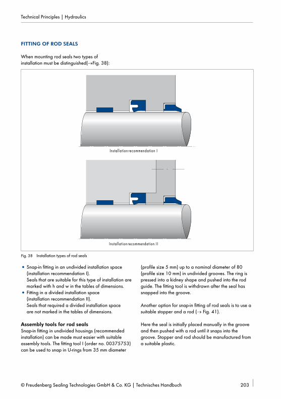
When mounting rod seals two types of installation must be distinguished(→Fig. 38):
Ins ta l la t ion recommendat ion I
Ins ta l la t ion recommendat ion I I
Fig. 38 Installation types of rod seals
• Snap-in fitting in an undivided installation space (installation recommendation I). Seals that are suitable for this type of installation are marked with h and w in the tables of dimensions.
• Fitting in a divided installation space (installation recommendation II). Seals that required a divided installation space are not marked in the tables of dimensions.
Assembly tools for rod sealsSnap-in fitting in undivided housings (recommended installation) can be made must easier with suitable assembly tools. The fitting tool I (order no. 00375753) can be used to snap in U-rings from 35 mm diameter
(profile size 5 mm) up to a nominal diameter of 80 (profile size 10 mm) in undivided grooves. The ring is pressed into a kidney shape and pushed into the rod guide. The fitting tool is withdrawn after the seal has snapped into the groove.
Another option for snap-in fitting of rod seals is to use a suitable stopper and a rod (→ Fig. 41).
Here the seal is initially placed manually in the groove and then pushed with a rod until it snaps into the groove. Stopper and rod should be manufactured from a suitable plastic.
Fitting of groove and compact seals with back-up ringThe Merkel SM U-Ring (primary seal) with locked-in back-up ring can be snapped into a plunge-cut groove. The sealing ring is first inserted into the groove. Then the back-up ring is installed.Compact seals with a locked-in back-up ring can be snapped into a plunge-cut groove, depending on the diameter and profile.
Fitting of multi-part compact seals for the rod: Merkel Omegat OMS-MRFor rod diameters ≤15 mm an axially accessible hous-ing is required. Up to rod diameter 28 mm an axially accessible housing is recommended. If this is not pos-sible for design reasons, the seal must be selected in accordance with the smaller installation size L.For diameter range 38 to 50 mm we also recommend using the seal in accordance with the smaller fitting size L because of the easier fitting (→ Fig. 41). The max. permissible gap widths of the type must be observed.
Fig. 39 Fitting tool I for rod seals
Fig. 40 Fitting tool II for rod seals
Fitting in divided housingsFrom a specific nominal diameter, depending on the profile size, rod seals must be installed in divided housings. The limit sizes are listed in d (→ Tbl. 8).
Rod seals in divided housings (fitting recommendation II) can be installed without special tools. For series installation we recommend using mounting sleeves and pilot shafts (→ Fig. 42).
U-rings and single-piece compact seals
Profile size
P = DN – dN
_________
2 4 5 6 7,5 10 12,5 15
Limit nominal di-ameters for snap-in fitting
25 30 40 50 80 100 105
Seals that are suitable for snap-in fitting are identified with h (hand) in the descriptions in the dimension lists.
Tbl. 8 Limit dimensions for snap-in fitting (required values)
Similar to fitting of rod seals there are also two types of installation of piston seals:
• Snap-in fitting in undivided housings.Seals that are suitable for this type of installation are identified with h or w in the dimension tables.
• Fitting in divided housings.When assembled the metal parts must adhere to preclude extrusion wear on the static side.
Multi-part compact seals for pistonsSimko Piston Seals can generally be snapped in without tools. The following illustrations show the snap-in fitting without tools for the Merkel Compact Seal Simko 300 Compact Seal. First the elastic rubber contact pressure element is snapped in. Then the PUR sealing ring is placed on one side in the groove and pushed over the previously oiled piston body until it snaps completely into the groove.
Assembly tools for piston sealsThe snap-in fitting is made much easier with suitable assembly tools.
Fig. 45 Fully mounted seal
Fig. 46 Inserting sealing ring
Simko Piston Seals as well as U-Rings that in some cases are used as single-acting piston seals can be easily in-stalled with the aid of simple installation toolSee the following illustrations:
FITTING OF COMPACT SEALS OF THE OMEGAT SERIES FOR PISTONS AND RODSThe Merkel Omegat Compact Piston Seals (OMK-MR, OMK-S, OMK-E, OMK-ES) and the Merkel Omegat Compact Rod Seals (OMS-MR, OMS-S) are suitable for undivided housings in virtually all dimensions. Fitting requires special care.
To prevent damage to the sealing edge, which may result in leakage before commissioning, it is important to observe our installation instructions.
Fitting for installationOmegat Seals consist of a high-quality pressure and wear-resistant profile ring and an O-ring as the pre-load component. Careful fitting is essential for correct function.
Before starting installation, make sure that:
• The required insertion chamfers on the piston rod and cylinder bore have been de-burred and round-ed,
• Thread peaks and sharp edges are covered,• Dust, dirt, chips and other external objects must be
thoroughly removed,• The Omegat sealing components and the compo-
nents are oiled or greased (use only greases without solid additives. In this regard make sure that they are compatible with the medium.),
• The assembly tools must be of soft material and have no sharp edges.
Heating them in oil up to about 80 °C makes it much easier to stretch and deform the Omegat Profile Ring.
Omegat Rod Seal
Fitting of Omegat Rod Seals in undivided housings is very easy (d ≤Ø15 axially accessible housing required):
Insert O-ring into the groove without twisting it.
Press Omegat Profile Ring into a kidney shape (attention: do not kink!).
Place compressed Omegat Profile Ring on the O-ring so the sealing edge is on the pressure side.
Insert Omegat Profile Ring in original shape in the groove.
Then calibrate with a mandrel. The mandrel can be manufactured from PA, POM or similar material. Chamfers of 15° and minimum 30 mm long.
Tbl. 9 Deformation of the profile ring
Ø d L Ø d mandrel
<50 15 Ø d – 0,10
≥ 50 ... <120 20 Ø d – 0,18
≥120 ... <200 30 Ø d – 0,25
≥200 ... <650 40 Ø d – 0,35
≥650 ... <900 50 Ø d – 0,50
Tbl. 10 Recommended diameter of mounting equipment
Recommendation:Please use an assembly tool when d Ø>15 mm and for larger series. This deforms the profile ring less. The major design principles are shown in the drawing.
Omegat Piston Seals must always be fitted in single-piece pistons with a fitting tool.
Insert O-Ring into the groove without twisting it. Expanding sleeve
Expanding mandrel approx. 5°chamfer
O-ring
PTFE profile ring
Stretch Omegat Profile Ring with spreader sleeve over a tapered mounting sleeve and spring into the groove, for larger dimensions use mounting belt (order no. 24346745) (no sharp-edged tools).
Calibrate Omegat Profile Ring on the piston diameter with a slip ring. When using profile rings with an L-dimension ≥6,3 mm we recommend using a plastic tension belt.
Tbl. 11 Mounting equipment for piston seal
1. Back-up ring
2. Sealing component
3. Back-up ring
4. Angled bush
4. 1. 2. 3. 4.
FITTING INSTRUCTIONS FOR MERKEL COMPACT SEAL L 43Fitting of the Merkel Compact Seal L 43 is uncompli-cated and generally corresponds to the conventional compact piston seal. The assembly should be carried out in the sequence below.
Fig. 52 Fitting of Merkel Compact Seal L 43
FITTING OF MERKEL COMPACT SEAL T 19We recommend using installation tools for all dimen-sions of the size series T 19; hand installation is possible for servicing. The sequence when mounting the individu-al parts is as follows:
• First angled bush• Sealing component• Second angled bush
INSTALLATION INSTRUCTIONS FOR MERKEL DOUBLE WIPER PT 2Double wipers of the PT 2 series can be installed in housings that are not axially accessible without tools from Ø150 mm. For installation first insert the large O-ring into the groove, insert the small O-ring into the groove of the PTFE profile ring, then the profile ring is placed in a kidney shape and snapped in. Make sure that the profile ring is not kinked and that the sealing edge is correctly aligned to the pressure direction. For smaller dimensions please use an installation tool.Dimensions <Ø100 mm cannot be installed in a plunge-cut groove.
INSTALLATION INSTRUCTIONS FOR MERKEL DOUBLE WIPER PT 1Double wipers of the PT 1 series with inside diameter ≥30 mm can be installed in non-axially accessible housings without fitting tools. For smaller dimensions a fitting tool is recommended.
PT 1
Pressure
Fig. 53 Functional direction of wiper
For installation the O-rings are inserted into the groove, then the profile ring is placed in a kidney shape and snapped in. Make sure that the profile ring is not kinked and the sealing edge is correctly aligned to the pressure direction.
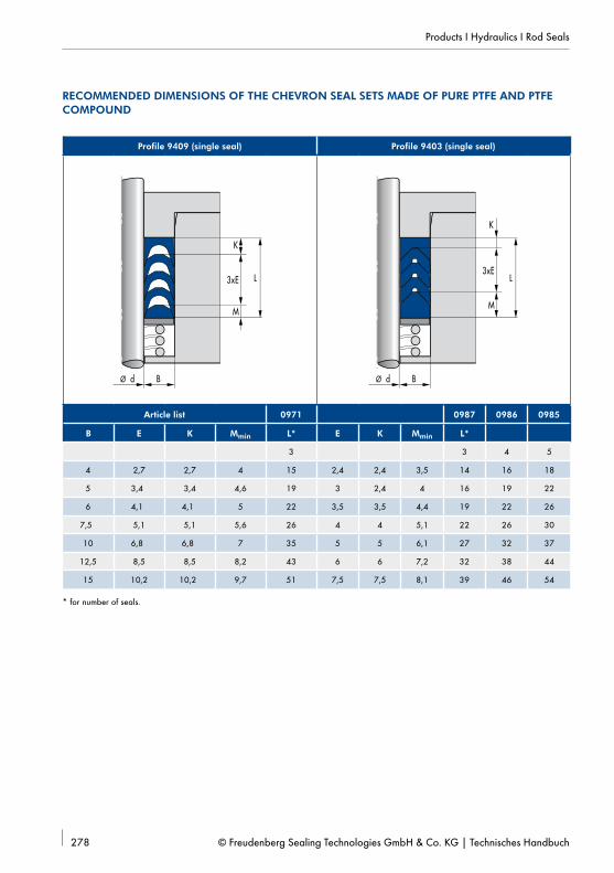
FITTING OF CHEVRON SEAL SETS
Instructions for Chevron Seal Set housingsAdjustable housings have the advantage of an optimal adjustment option. After a lengthy period of running and incipient wear on the seal tightening the gland can extend the service life and significantly delay a system standstill. For adjustable housings an extension of 2,5% and an adjustability of 7,5% of dimension L is recom-mended. Non-adjustable housings have the advantage of more cost-effective manufacture, because washers are not required. Seal Set Type B is particularly recom-mended for these housings. The rubber-sprung back-up rings handle the function of initial compression and con-tinuous re-adjustment during operation. Maintenance of the seal contact area is not required.
FittingBefore installation all individual parts of the seal set must be evenly greased. Mineral-oil-based greases can be used. The rod must be in the cylinder’s installation space during fitting. The individual parts of the set must be installed separately in the chamber. In this regard make sure that the seals are not reversed. Open chevron seal sets are used for repairs, e.g. in large systems, if endless seals cannot be installed.
Please noteOpen chevron seals have an oversize in the circumfer-ence length to allow sufficient compression and a good sealing effect at the joint sections. An endless delivered seal set should therefore not be cut. Open chevron seals are always supplied with installed profile cords.
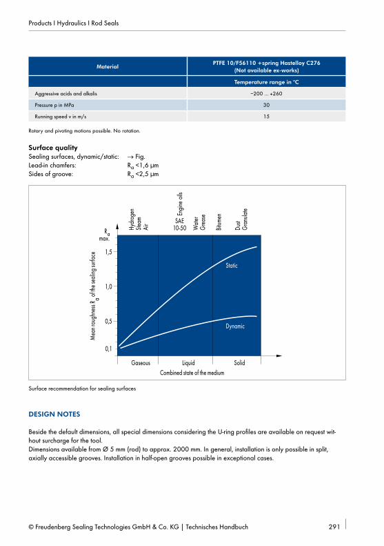
We recommend installation of Merkel Forseal Seals in divided grooves.In exceptional cases there is also the option of snap-in fitting in semi-open grooves. We request you consult us in these t applications. The sealing ring must not be kinked during fitting.
Installation instructions for Merkel Forseal FOI made of PTFE
Groove cross- section
O-Ring Ø Xmin
can be installed
from FOI-L
1,45 x 2,4 1,78 0,2 12 4,0
2,25 x 3,6 2,62 0,3 20 4,5
3,10 x 4,8 3,53 0,5 30 5,0
4,70 x 7,1 5,33 0,6 40 7,0
6,10 x 9,5 7,00 0,7 55 9,0
Tbl. 12 Rod housing
30°
15°
X
DND1 L
ØØ
Rod
Housing
Rounded
Fig. 55 Installation in half-open grooves/snap-in fitting Merkel Forseal FOI
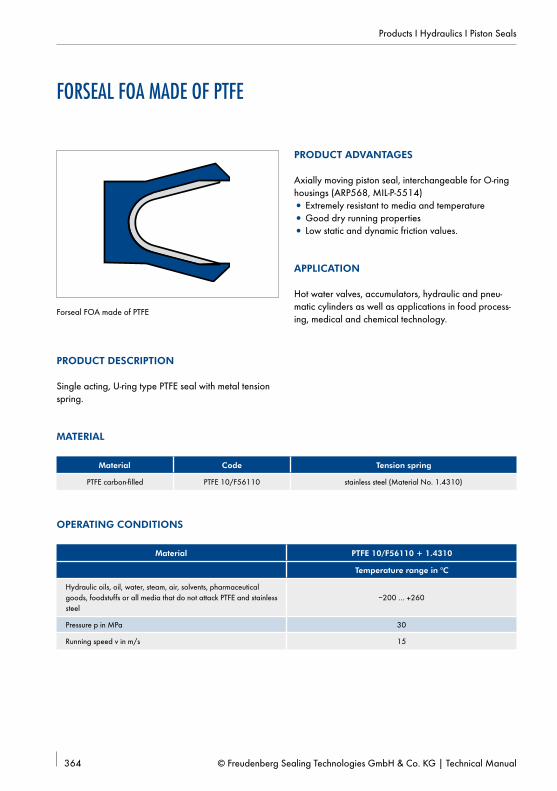
Installation instructions for Merkel Forseal FOA made of PTFE
Groove cross- section
O-Ring Ø Xmincan be installed
from FOA-L
1,45 x 2,4 1,78 0,4 15 4,0
2,25 x 3,6 2,62 0,6 20 4,5
3,10 x 4,8 3,53 0,7 25 5,0
4,70 x 7,1 5,33 0,8 30 7,0
6,10 x 9,5 7,00 0,9 45 9,0
Tbl. 13 Piston housing
15°
L
30°
X
dN d1Ø Ø
Piston
Housing
Rounded
Fig. 56 Installation in half-open grooves/snap-in fitting Merkel Forseal FOA
Pre-Selection Piston Seals 292Merkel U-Ring NA 150 298Merkel U-Ring NA 250 300
B Merkel U-Ring NA 300 302Merkel U-Ring NA 400 304
B Merkel U-Ring T 18 306 B Merkel U-Ring TM 21 308 B Merkel U-Ring TMP 21 311
Merkel Compact Seal T 42 313Merkel Compact Seal T 44 316Merkel U-Ring Seal Set 0215 318Merkel U-Ring Seal Set 0217 321Merkel Omegat OMK-PU 324
B Merkel Omegat OMK-E 326 B Merkel Omegat OMK-ES 330 B Merkel Omegat OMK-MR 333 B Merkel Omegat OMK-S 336
Merkel Compact Seal Simko 300 339Merkel Compact Seal Simko 320 X2 342Merkel Compact Seal Simko 520 344Merkel Compact Seal L 27 346Merkel Compact Seal L 43 349Merkel Compact Seal T 19 351Merkel Compact Seal TFMA 353Merkel Complete Piston TDUOH 355Merkel Cup Packing T with Spring 357Merkel Cup Packing T without Spring 359Merkel Chevron Seal Set EK, EKV 361Forseal FOA made of PTFE 364
PRODUCTSA B marks types to be preferably used with new designs
ROD SEALS
Pre-Selection Rod Seals 214 B Merkel U-Ring LF 300 220
Merkel U-Ring NI 150 222Merkel U-Ring NI 250 224
B Merkel U-Ring NI 300 226Merkel U-Ring NI 400 228
B Merkel U-Ring T 20 230Merkel U-Ring T 22 233Merkel U-Ring T 23 235
B Merkel U-Ring T 24 237 B Merkel U-Ring TM 20 239
Merkel U-Ring TM 23 242 B Merkel U-Ring Syprim SM 244
Merkel U-Ring Seal Set 0214 246Merkel U-Ring Seal Set 0216 249
B Merkel U-Ring TMP 20 252 B Merkel Omegat OMS-MR 254 B Merkel Omegat OMS-MR PR 257 B Merkel Omegat OMS-S 260 B Merkel Omegat OMS-S PR 262 B Merkel Compact Seal KI 310 265 B Merkel Compact Seal KI 320 267
Merkel Compact Seal S 8 269Merkel Compact Seal TFMI 271Merkel Chevron Seal Set ES, ESV 273Chevron Seal Set made of PTFE 276Packing Ring TFW made of PTFE 280Merkel V-Packings V 1000 282Merkel Hat Seal H with Spring 286Merkel Hat Seal H without Spring 288Forseal FOI made of PTFE 290
Pre-Selection Wipers 366Merkel Wiper AS 370Merkel Wiper ASOB 372
B Merkel Wiper AUPS 374 B Merkel Wiper AUAS 376 B Merkel Wiper AUAS R 378
Merkel Wiper AUASOB 380Merkel Wiper P 6 382
B Merkel Wiper PU 5 384 B Merkel Wiper PU 6 386
Merkel Wiper PU 7 388Merkel Double Wiper P 8 390Merkel Double Wiper P 9 392
B Merkel Double Wiper PRW 1 with Integrated Pressure Relief 394
B Merkel Double Wiper PT 1 396 B Merkel Double Wiper PT 2 398 B Merkel Double Wiper PU 11 400
GUIDES
Pre-Selection Guides 402Merkel Guide Ring EKF 406
B Merkel Guide Ring FRA 408 B Merkel Guide Ring KB 410 B Merkel Guide Ring Guivex KBK 412 B Merkel Guide Strip KF 415 B Merkel Guide Ring FRI 419 B Merkel Guide Ring Guivex SBK 421 B Merkel Guide Ring SB 424 B Merkel Guide Strip SF 426
PROFILES FOR OSCILLATING APPLICATIONS
429
Pre-Selection Other Seals 434
SEALS FOR SWIVELLING MOVEMENT
B Merkel Rotomatic M 15 438 B Merkel Rotomatic M 16 440
Merkel Rotomatic M 17 442Merkel Rotomatic M 19 444
RADIAL AND AXIAL SEALS
Simmerring Radiamatic® EWDR made of PTFE 446Simmerring Radiamatic® HTS II made of PTFE 449Simmerring Radiamatic® R 35 451Simmerring Radiamatic® R 36 453Simmerring Radiamatic® R 37 455Simmerring Radiamatic® R 58 457Simmerring Radiamatic® R 35 LD 459Simmerring Radiamatic® RS 85 461Simmerring Radiamatic® RHS 51 463
SYMMETRIC SEALS
Merkel U-Ring N 1, AUN 1 466Merkel U-Ring N 100, AUN 100 468
STATIC SEALS
B Merkel Cover Seal PU 82 470 B Merkel Cover Seal PU 83 472 B Merkel Stircomatic SRC 474
Temperature figures refer to mineral oils. Due to the large choice of media with different and varying additives, which is not always easily comprehensible, the above operating limits are only recommended values. We recom-mend testing resistance in the specific case.Individual instances of the operating limits stated may be exceeded taking into account the related operating condi-tions. With a long duty cycle, stop-start operation or other difficult operating conditions it is recommended that these values are not simultaneously exploited to the full.
For high requirements in sealing systems, low friction, free of stick-slip, high temper-ature resistance/ high heat
dissipation ability.
B E B B 40 5 –30 … +100
Omegat OMS-S
Elastomer profile ring
PTFE profile ring PTFE glass NBR
Very high resistance to pres-sure, specifically for heavy duty
hydraulic applications, low friction, free of stick-slip, high contact pressure and design
which prevents twisting through elastomer profile ring.
B E B B 40 5 –30 … +100
Omegat OMS-MR PR
O-ring
Pressure relief boring
PTFE profile ring
PTFE bronze NBRPTFE bronze FKM PTFE glass NBR
based on 7425/2
Patented pressure relief for high reliability, for high requirements in sealing systems, low friction, free of stick-slip, high tempera-ture resistance/heat dissipation
ability.
B E B E 40 5 –30 … +100
B = very good; C = good; D = possibile or satisfactory; E = not suitable
Merkel U-ring with asymmetrical profile, inner lip set back, grooved contact surface on the inside diameter as well as press fit at the outside diameter.
PRODUCT ADVANTAGES
Single-acting rod seal for standardised housings, amongst others, according to ISO 5597• Very good static and dynamic tightness• Low friction, smooth movement even at low running
speeds, dynamic deformation value• Use as an individual seal or secondary seal in
If the U-ring LF 300 is used as a secondary seal, running speeds up to 0,8 m/s can be allowed.
Surface quality
Surface roughness Ra Rmax
Sliding surface 0,05 … 0,3 µm ≤2,5 µm
Groove base ≤1,6 µm ≤6,3 µm
Groove flanks ≤3,0 µm ≤15,0 µm
Percentage contact area Mr >50% to max. 90% at cutting depth c = Rz/2 and reference line C ref = 0%.
DESIGN NOTES
Please observe our general design notes.
Gap dimensionThe decisive factor for the function of the seal is the largest gap dimension occurring during operation on the non-pressurised side of the seal.
Profile Max. permissible gap dimension
16 MPa 26 MPa 32 MPa
4,0 … 5,0 0,50 0,40 0,35
>5,0 … 7,5 0,55 0,45 0,40
Tolerance recommendation and dimension D2The admissible gap width, tolerances, guide play and deflection of the guide under load are to be taken into ac-count when designing D2.
Nominal Ø d d D
≤180 f8 H11
FITTING & INSTALLATION
Careful fitting is a prerequisite for the correct function of the seal.
Gap dimensionThe decisive factor for the function of the seal is the largest gap dimension occurring during operation on the non-pressurised side of the seal.
Profile Max. permissible gap dimension
2,5 MPa 5 MPa 7,5 MPa 10 MPa
≤5 0,45 0,30 0,25 0,20
>5 0,50 0,35 0,30 0,25
Tolerance recommendation and dimension d2The admissible gap width, tolerances, guide play and deflection of the guide under load are to be taken into ac-count when designing D2.
Nominal Ø d d D
≤180 f8 H11
FITTING & INSTALLATION
Careful fitting is a prerequisite for the correct function of the seal.
Gap dimensionThe decisive factor for the function of the seal is the largest gap dimension occurring during operation on the non-pressurised side of the seal.
Profile Max. permissible gap dimension
7,5 MPa 10 MPa 25 MPa
≤80 0,95 0,80 0,60
>80 1,00 0,85 0,65
Tolerance recommendation and dimension d2The admissible gap width, tolerances, guide play and deflection of the guide under load are to be taken into ac-count when designing D2.
Nominal Ø d d D
≤120 f8 H11
FITTING & INSTALLATION
Careful fitting is a prerequisite for the correct function of the seal.
Merkel U-ring with asymmetrical profile, inner lip set back, additional support edge and sealing edge as well as press fit at the outside diameter.
PRODUCT ADVANTAGES
Single-acting rod seal for standardised housings, amongst others, according to ISO 5597• Very good static and dynamic tightness• Additional sealing edge, prevents ingress of dirt to
a large degree• Recommended for use in combination with single-
acting wipers.
APPLICATION
Earth moving equipment, support cylinders, cranes, presses.
MATERIAL
Material Code Härte
Polyurethan 94 AU 925 94 Shore A
OPERATING CONDITIONS
Material 94 AU 925
Temperature range in °C
Hydraulic oils HL, HLP –30 … +110
HFA fluids +5 … +50
HFB fluids +5 … +50
HFC fluids –30 … +40
HFD fluids –
Water +5 … +40
HETG (rapeseed oil) –30 … +60
HEES (synthetic ester) –30 … +60
HEPG (glycol) –30 … +40
Mineral greases –30 … +110
Pressure p in MPa 40
Running speed v in m/s 0,5
Surface quality
Surface roughness
Ra Rmax
Sliding surface 0,05 … 0,3 µm ≤2,5 µm
Groove base ≤1,6 µm ≤6,3 µm
Groove flanks ≤3,0 µm ≤15,0 µm
Percentage contact area Mr >50% to max. 90% at cutting depth c = Rz/2 and reference line C ref = 0%.
Gap dimensionThe decisive factor for the function of the seal is the largest gap dimension occurring during operation on the non-pressurised side of the seal.
Profile Max. permissible gap dimension
16 MPa 26 MPa 32 MPa 40 MPa
4,0 … 5,0 0,50 0,40 0,35 0,30
>5,0 … 7,5 0,55 0,45 0,40 0,35
>7,5 … 12,5 0,66 0,50 0,45 0,40
>12,5 0,60 0,55 0,50 0,45
Tolerance recommendation and dimension d2The admissible gap width, tolerances, guide play and deflection of the guide under load are to be taken into ac-count when designing D2.
Nominal Ø d d D
4 … 260 f8 H11
FITTING & INSTALLATION
Careful fitting is a prerequisite for the correct function of the seal.
Merkel U-ring with asymmetrical profile of the sealing lips, fabric reinforcement on the dynamic sealing side and back-up ring as a gap sealing component.
PRODUCT ADVANTAGES
Single-acting rod seal for medium loads, predominantly for spare parts requirements.
APPLICATION
Heavy duty earth moving equipment, industrial vehicles, presses, control and regulation equipment.
MATERIAL
Sealing component
Material Code Hardness
Nitrile rubber NBR
80 NBR 878 80 Shore A
Back-up ring
Material Code
Polyacetal POM 992020
OPERATING CONDITIONS
Material 80 NBR 878/POM
Temperature range in °C
Hydraulic oils HL, HLP –30 … +100
HFA fluids +5 … +60
HFB fluids +5 … +60
HFC fluids –30 … +60
HFD fluids –
Water +5 … +90
HETG (rapeseed oil) –30 … +80
HEES (synthetic ester) –
HEPG (glycol) –30 … +60
Mineral greases –30 … +100
Pressure p in MPa 40
Running speed v in m/s 0,5
Surface quality
Surface roughness
Ra Rmax
Sliding surface 0,05 … 0,3 µm ≤2,5 µm
Groove base ≤1,6 µm ≤6,3 µm
Groove flanks ≤3,0 µm ≤15,0 µm
Percentage contact area Mr >50% to max. 90% at cutting depth c = Rz/2 and reference line C ref = 0%.
Gap dimensionThe decisive factor for the function of the seal is the largest gap dimension occurring during operation on the non-pressurised side of the seal.
Profile Max. permissible gap dimension
16 MPa 26 MPa 32 MPa 40 MPa
≤80 0,60 0,50 0,40 0,35
>80 0,65 0,55 0,45 0,40
Tolerance recommendation and dimension D2The admissible gap width, tolerances, guide play and deflection of the guide under load are to be taken into account when designing D2.
Nominal Ø d d D
≤360 f8 H11
FITTING & INSTALLATION
Careful fitting is a prerequisite for the correct function of the seal.
Merkel U-ring with asymmetrical profile, inner lip set back and press fit at the outside diameter.
PRODUCT ADVANTAGES
Single-acting rod seal for standardised housings, amongst others, according to ISO 5597; very suitable as a secondary seal within a sealing system• Good media resistance• Wide operating temperature range• Very good static and dynamic tightness• Low breakaway force (in comparison to compact
seals or U-rings with secondary sealing edge in cor-responding material)
• Dynamic deformation value.
APPLICATION
Earth moving equipment, agricultural machinery, injec-tion moulding machines, support cylinders, cranes, loa-ding platforms, fork-lift trucks, standard cylinders.
* If a Merkel U-Ring T 20 is used as a secondary seal, higher running speeds may be permitted.
Surface quality
Surface roughness Ra Rmax
Sliding surface 0,05 … 0,3 µm ≤2,5 µm
Groove base ≤1,6 µm ≤6,3 µm
Groove flanks ≤3,0 µm ≤15,0 µm
Percentage contact area Mr >50% to max. 90% at cutting depth c = Rz/2 and reference line C ref = 0%.
DESIGN NOTES
Please observe our general design notes.
Gap dimensionThe decisive factor for the function of the seal is the largest gap dimension occurring during operation on the non-pressurised side of the seal.
ProfileMax. permissible gap dimension
16 MPa 26 MPa 32 MPa 40 MPa
<5,0 0,45 0,4 0,35 –
>5,0 … 7,5 0,50 0,45 0,4 0,35
>7,5 … 12,5 0,55 0,5 0,45 0,4
15,0 0,60 0,55 0,45 0,4
The dimensions D1 and DF are to be viewed in connection with the guide elements used.
Tolerance recommendation and dimension D2The admissible gap width, tolerances, guide play and deflection of the guide under load are to be taken into account when designing D2.
Merkel polyurethane U-ring with asymmetrical profile, shortened inner lip and second support edge and sealing edge as well as press fit at the outside diameter.
PRODUCT ADVANTAGES
Single-acting rod seal, also for standardised housings according to ISO 5597• Highly wear-resistant• Good media resistance• Wide operating temperature range• Very good static and dynamic tightness• (Note: low deformation value, therefore not suitable
for sealing systems).
APPLICATION
Earth moving equipment, support cylinders, marine hydraulics, mobile hydraulics. We recommend more modern series for new designs.
Gap dimensionThe decisive factor for the function of the seal is the largest gap dimension occurring during operation on the non-pressurised side of the seal.
Profile Max. permissible gap dimension
L Profile 16 MPa 26 MPa 32 MPa 40 MPa
8 … 13 5,0 0,50 0,40 0,35 –
11 … 13 7,5 0,55 0,45 0,40 0,35
11 … 16 10,0 0,60 0,50 0,45 0,40
≥16 12,5 0,60 0,50 0,45 0,40
Tolerance recommendation and dimension D2The admissible gap width, tolerances, guide play and deflection of the guide under load are to be taken into ac-count when designing D2.
Nominal Ø d d D
15 … 160 f8 H10
FITTING & INSTALLATION
Careful fitting is a prerequisite for the correct function of the seal.
Two-piece Merkel seal set with shortened inner lip and active back-up ring with press fit at the outside diameter.
PRODUCT ADVANTAGES
The Merkel U-Ring T 23 is mainly used with high pressures and is designed for housings according to ISO 5597• Bridges large gaps even with high pressures• Wide operating temperature range• Very good static and dynamic tightness• High resistance to wear.
APPLICATION
Earth moving equipment, steel hydraulics engineering, heavy-duty mobile hydraulics, marine hydraulics, support cylinders, scrap cutters.
MATERIAL
Material Code Hardness
Polyurethane 95 AU V142 95 Shore A
Material Code
Polyacetal POM PO202
OPERATING CONDITIONS
Material 95 AU V142/POM PO202
Temperature range in °C
Hydraulic oils HL, HLP –30 … +110
HFA fluids +5 … +50
HFB fluids +5 … +50
HFC fluids –30 … +40
HFD fluids –
Water +5 … +50
HETG (rapeseed oil) –30 … +60
HEES (synthetic ester) –30 … +80
HEPG (glycol) –30 … +50
Mineral greases –30 … +110
Pressure p in MPa 50
Running speed v in m/s 0,1
Surface quality
Surface roughness
Ra Rmax
Sliding surface 0,05 … 0,3 µm ≤2,5 µm
Groove base ≤1,6 µm ≤6,3 µm
Groove flanks ≤3,0 µm ≤15,0µm
Percentage contact area Mr >50% to max. 90% at cutting depth c = Rz/2 and reference line C ref = 0%.
Gap dimensionThe decisive factor for the function of the seal is the largest gap dimension occurring during operation on the non-pressurised side of the seal.
Tolerance recommendation and dimension D2The admissible gap width, tolerances, guide play and deflection of the guide under load are to be taken into ac-count when designing D2. Dimensions D1 and DF must be considered in connection with the guide element used.
Careful fitting is a prerequisite for the correct function of the seal. Dimensions listed in the table of dimensions with "h" can be fitted by hand into plunge-cut grooves. Articles identified with "w" can be easily fitted into plunge-cut grooves with a fitting tool. We will be pleased to supply a design drawing for this on enquiry.
Merkel U-ring with asymmetrical profile, inner lip set back, additional support edge and sealing edge and press fit at the outside diameter.
PRODUCT ADVANTAGES
Single-acting rod seal especially for telescopic cylinders and radially restricted housings• Very good static and dynamic tightness• Additional sealing edge prevents ingress of dirt to a
large degree• (Note: low dynamic deformation value, therefore not
Gap dimensionThe decisive factor for the function of the seal is the largest gap dimension occurring during operation on the non-pressurised side of the seal.
Profile Max. permissible gap dimension
16 MPa 26 MPa 32 MPa
4 0,50 0,40 0,35
Tolerance recommendation and dimension D2The admissible gap width, tolerances, guide play and deflection of the guide under load are to be taken into ac-count when designing D2.
16 MPa 26 MPa 32 MPa
Nominal Ø d d D d D d D
45 … 171 f8 H8 f8 H8 f8 H8
FITTING & INSTALLATION
Careful fitting is a prerequisite for the correct function of the seal.
Merkel U-ring with asymmetrical profile, inner lip set back and press fit at the outside diameter.
PRODUCT ADVANTAGES
Single-acting rod seal for hydraulic cylinders. With new production technology even special sizes can be manuf-actured quickly and flexibly• Good media resistance• Wide operating temperature range
• Very good static and dynamic tightness• Use as an individual seal or as a secondary seal in
sealing systems possible• Large range of dimensions• No moulding tools.
APPLICATION
Injection moulding machines, presses, heavy machinery manufacture, large cylinders.
* If TM 20 is fitted in a sealing system as a secondary seal, higher running speeds can be allowed.
Surface quality
Surface roughness Ra Rmax
Sliding surface 0,05 … 0,3 µm ≤2,5 µm
Groove base ≤1,6 µm ≤6,3 µm
Groove flanks ≤3,0 µm ≤15,0 µm
Percentage contact area Mr >50% to max. 90% at cutting depth c = Rz/2 and reference line C ref = 0%.
DESIGN NOTES
Please observe our general design notes.
Tolerance recommendation and dimension D2D2 "System" is based on the use of Merkel TM 20 as a secondary seal in a sealing system. The specified D2 dimen-sions are based on the use of Merkel fabric-base laminate guide ring SB or metal guide. They provide high security against gap extrusion and also metal tarnish. If the stated operating parameters range is not fully exploited or only for a short period, larger D2 dimensions may be selected. With high lateral forces or high deflection we recom-mend a metal guide.
Housing recommendations for new designsMerkel U-Ring TM 20 primary seal
d D L C
>320 … 600 d + 30 25 11
>320 … 720 d + 40 32 12
>720 … 2000 d + 40 40 16
Merkel U-Ring TM 20 secondary seal in the sealing system
* Profiles in accordance with "housing recommendations for new designs" ** Use fit or tolerance level of primary seal
Lead-in chamfersDimension C.
FITTING & INSTALLATION
The rod seals can be fitted into plunge-cut grooves by hand or with a fitting tool. In the case of different housings, e.g. in old plant, please ask our advisory service.
The Merkel U-Ring TM 23 is specially designed for sealing the piston rods of plungers, pushers and subsi-diary cylinders in self-advancing support systems.
PRODUCT ADVANTAGES
To meet the requirements of a higher radial deflection and larger gap bridging, the Merkel U-Ring TM 23 has been fitted with an increased pre-load and active back-up ring. The second sealing edge provides extra protection against the ingress of dirt particles.• Good media resistance• Very good static and dynamic tightness• Large range of dimensions• Bridges large gaps• Highly wear-resistant.
APPLICATION
Mining.
MATERIAL
Material Code Hardness
Novathan (polyurethane)
95 AU V157/ 93 AU V167
95 Shore A/93 Shore A
OPERATING CONDITIONS
Material 95 AU V157/ 93 AU V167
Temperature range in °C
HFA fluids/water +5 … +60
Pressure p in MPa 50
Running speed v in m/s <0,1*
Surface quality
Surface roughness
Ra Rmax
Sliding surface 0,05 … 0,3 µm ≤2,5 µm
Groove base ≤1,6 µm ≤6,3 µm
Groove flanks ≤3,0 µm ≤15,0 µm
Percentage contact area Mr >50% up to max. 90% at cutting depth c = Rz/2 and reference line C ref = 0%.
Gap dimensionThe decisive factor for the function of the seal is the largest gap dimension occurring during operation on the non-pressurised side of the seal.
Profile Max. permissible gap dimension
L Profile 16 MPa 26 MPa 32 MPa 50 MPa
12,5 7,5 0,8 0,7 0,50 0,4
>12,5 … 16 >7,5 … 10,0 1,2 1,0 0,65 0,5
>16 >10,0 1,8 1,4 0,90 0,7
Tolerance recommendation and dimension d2The admissible gap width, tolerances, guide play and deflection of the guide under load are to be taken into ac-count when designing d2.
Nominal Ø d d D
≤350 f7 H10
FITTING & INSTALLATION
The U-rings can be fitted into plunge-cut grooves by hand or with a fitting tool. We will be pleased to send you a design drawing for this on enquiry.
Two-piece Merkel seal set for use as a primary rod seal. The Merkel Syprim SM seal set is always used in a sealing system in combination with U-ring (e.g. Merkel U-Ring T 20).
PRODUCT ADVANTAGES
The Merkel U-Ring Syprim SM is designed especially for use as a system seal• Short primary seal• No pressure enclosed between primary and se-
condary seal• Low friction• Highly wear-resistant• Protection against extrusion through activated back-
Percentage contact area Mr >50% to max. 90% at cutting depth c = Rz/2 and reference line C ref = 0%.
DESIGN NOTES
Please observe our general design notes.
Gap dimensionThe decisive factor for the function of the seal is the largest gap dimension occurring during operation on the non-pressurised side of the seal.
Profile Max. permissible gap dimension
L Profile 16 MPa 26 MPa 32 MPa 40 MPa
6,3 7,55 0,6 0,5 0,4 0,4
8,1 10,25 0,7 0,6 0,5 0,5
Tolerance recommendation and dimension D2The admissible gap width, tolerances, guide play and deflection of the guide under load are to be taken into ac-count when designing D2.
Nominal Ø d d D
45 … 80 f8 H9
>80 … 200 f8 H8
FITTING & INSTALLATION
Careful fitting is a prerequisite for the correct function of the seal.
Two-piece Merkel seal set comprising an elastomer U-ring with an elastomer sealing edge, fabric reinforce-ment on the contact area and an active back-up ring.
PRODUCT ADVANTAGES
Single-acting rod seal for use in hydraulics and pneumatics• Low friction due to fabric reinforcement• Large range of dimensions• Protection against extrusion through activated
back-up ring• Low deformation value (not suitable for sealing
systems)• Easily installed in non-axial housings • From 100 mm diameter.
APPLICATION
Injection moulding machines, iron and steel technology, presses, special cylinders, marine hydraulics, steel hydraulics engineering, scrap cutters.
MATERIAL
U-Ring
Material Code
NBR 80 NBR B246
Cotton fabric BI-NBR B4 B248
Back-up ring
D Material Code
<300 mm Polyacetal POM POM PO202
>300 mm Polyamide PA 6.G200
Other materials like PTFE bronze back-up ring on enquiry.
For Merkel U-Ring Seal Sets 0214, if long strokes are traversed, the max. pressure should only be applied to the last part of the stroke (closing pressure); during the stroke max. 16 MPa.
Surface quality
Surface roughness Ra Rmax
Sliding surface 0,05 … 0,3 µm ≤2,5 µm
Groove base ≤1,6 µm ≤6,3 µm
Groove flanks ≤3,0 µm ≤15,0 µm
Percentage contact area Mr >50% to max. 90% at cutting depth c = Rz/2 and reference line C ref = 0%.
Gap dimension X2The decisive factor for the function of the seal is the largest gap dimension occurring during operation on the non-pressurised side of the seal.
Profile 16 MPa 26 MPa 32 MPa 40 MPa
D d X2 D d X2 D d X2 D d X2
<15 H10 f7 1,2 H10 f7 1,0 H10 f7 0,65 H10 f7 0,5
>15 H10 f7 1,8 H10 f7 1,4 H10 f7 0,9 H10 f7 0,7
The dimensions D1 and DF are to be viewed in connection with the sealing component used.
Tolerance recommendationThe admissible gap width, tolerances, guide play and deflection of the guide under load are to be taken into account when designing d2.
FITTING & INSTALLATION
Careful fitting is a prerequisite for the correct function of the seal.
Two-piece Merkel seal set comprising an elastomer U-ring with an elastomer sealing edge, fabric reinforce-ment on the contact area and an active back-up ring. Merkel U-Ring Seal Set 0216 can also be used for pneumatic applications.
PRODUCT ADVANTAGES
Single-acting rod seal for use in hydraulics and pneumatics• Low friction due to fabric part• Large range of dimensionse• Protection against extrusion through activated
back-up ring• Low deformation value (not suitable for sealing
systems)• Easily installed in non-axial housings • From 100 mm diameter.
APPLICATION
Pneumatic applications.
MATERIAL
U-Ring
Material Code
NBR 80 NBR B246
Cotton fabric BI-NBR B4 B248
Back-up ring
D Material Code
<300 mm Polyacetal POM POM PO202
>300 mm Polyamide PA 6.G200
Other materials like PTFE bronze back-up ring on enquiry.
For Merkel U-Ring Seal Sets 0216, if long strokes are traversed, the max. pressure should only be applied to the last part of the stroke (closing pressure); during the stroke max. 16 MPa.
Surface quality
Surface roughness Ra Rmax
Sliding surface 0,05 … 0,3 µm ≤2,5 µm
Groove base ≤1,6 µm ≤6,3 µm
Groove flanks ≤3,0 µm ≤15,0 µm
Percentage contact area Mr >50% to max. 90% at cutting depth c = Rz/2 and reference line C ref = 0%.
Gap dimension X2The decisive factor for the function of the seal is the largest gap dimension occurring during operation on the non-pressurised side of the seal.
Profile 16 MPa 26 MPa 32 MPa 40 MPa
D d X2 D d X2 D d X2 D d X2
<15 H10 f7 1,2 H10 f7 1,0 H10 f7 0,65 H10 f7 0,5
>15 H10 f7 1,8 H10 f7 1,4 H10 f7 0,9 H10 f7 0,7
The dimensions D1 and DF are to be viewed in connection with the sealing component used.
Tolerance recommendationThe admissible gap width, tolerances, guide play and deflection of the guide under load are to be taken into ac-count when designing d2.
FITTING & INSTALLATION
Careful fitting is a prerequisite for the correct function of the seal.
Single-acting rod seal made of abrasion-resistant poly-urethane.
PRODUCT ADVANTAGES
Rod seal for heavy-duty pneumatic stresses and strains and high operating requirements. New production technology allows special sizes to be manufactured quickly and flexibly. The Merkel U-rings are designed for pressure on one side• High tightness• Suitable for dry air• Large range of dimensions• No mould tools required.
Percentage contact area Mr >50% to max. 90% at cutting depth c = Rz/2 and reference line C ref = 0%. Abrasive surfaces, ridges, scratches and blow-holes must be avoided.
DESIGN NOTES
Please observe our general design notes.
Housing recommendations for new designs
d D L C
>50 … 200 d + 20 16 8,5
>100 … 320 d + 25 20 10,0
>150 … 630 d + 30 24 11,5
>400 … 800 d + 40 32 12,5
>800 … 1200 d + 50 40 16,0
>1000 … 2000 d + 60 48 18,0
FITTING & INSTALLATION
The rod seals can be inserted into plunge-cut grooves by hand or with a fitting tool. In the case of different housings, such as in old plant, please ask our advisory service. For optimum running-in and operation behaviour the U-rings should be lightly oiled or greased prior to use (initial lubrication).
Two-piece Merkel seal set made of PTFE profile ring with one O-ring as a pre-load component.
PRODUCT ADVANTAGES
Rod seal used in particular in a sealing system• Very high resistance to pressure• Good thermal conductivity• Very good extrusion resistance• High resistance to abrasion• Low friction, free of stick-slip.
APPLICATION
Industrial vehicles, handling equipment, agricultural ma-chinery, cranes, injection moulding machines, presses, marine hydraulics, control and regulation equipment, mills.
Percentage contact area Mr >50% to max. 90% at cutting depth c = Rz/2 and reference line C ref = 0%.
DESIGN NOTES
Please observe our general design notes.
Gap dimensionThe decisive factor for the function of the seal is the largest gap dimension occurring during operation on the non-pressurised side of the seal.
Tolerance recommendation and dimension D2The admissible gap width, tolerances, guide play and deflection of the guide under load are to be taken into ac-count when designing D2.
16 MPa 26 MPa 32 MPa 40 MPa
Nominal Ø d d D d D d D d D
≤ 80 f8 H9 f8 H9 f7 H9 f7 H7
>80 … 500 f8 H8 f8 H8 f7 H8 f7 H8
>500 … 1450 f8 H8 f7 H8 f7 H8 f7 H8
The dimensions D1 and DF are to be viewed in connection with the guide elements used.
FITTING & INSTALLATION
Careful fitting is a prerequisite for the correct function of the seal.
Two-component Merkel seal set for sealing piston rods, consisting of one PTFE profile ring with integrated pressure-relief function and an elastomer ring as pre-load component. Patented product design (patent no.: DE 10117662 CI).
PRODUCT ADVANTAGES
• Can be exchanged with operating environments of the Merkel Omegat OMS-MR Series. Increased operating reliability of sealing systems with deman-ding operating parameters (no continuously pressure build-up in gap area)
• Extended service life of sealing systems by long-term stability (reduced loading of the sealing system by minimised friction and wear).
APPLICATION
• Primary seal in a sealing system - longer stroke (greater than 400 mm)
• High stroke speed when piston rod extends (greater than 0,5 m/s)
• High speed differences depending on the direction of movement (V out greater than 8xV in)
• Fast pressure drop in main area• Large diameter (greater than 310 mm).Injection moulding machines, mills, agricultural machin-ery, presses, earth moving equipment, large cylinders, industrial vehicles, cranes, control and regulation equip-ment, marine hydraulics.
MATERIAL
PTFE profile ring
Material Code Colour
PTFE bronze compound PTFE B602 Brown
PTFE glass MoS2 compound PTFE GM201 Grey
PTFE carbon fibre compound PTFE C104 Dark grey
O-ring
Material Code
Nitrile rubber NBR
Other combinations of materials are available on enquiry.
The specified values are maximum values and must not be applied simultaneously.
Surface quality
Surface roughness Ra Rmax
Sliding surface 0,05 … 0,3 µm ≤2,5 µm
Groove base ≤1,6 µm ≤6,3 µm
Groove flanks ≤3,0 µm ≤15,0 µm
Percentage contact area Mr >50% to max. 90% at cutting depth c = Rz/2 and reference line C ref = 0%.
Gap dimensionThe dimension D2 is determined under load with reference to the maximum permissible extrusion gap, the tolerance levels, the guide play and the compressive deflection of the guide. The maximum permissible extrusion gap with one-sided position of the piston rod is primarily determined by the maximum operating pressure and the temperatu-re-dependent form stability of the sealing material.
At an operating temperature above 90°C and simultaneously applied operating pressure above 26 MPa we recommend the use of the material compounds PTFE B602 and PTFE C104.
MODE OF OPERATION
The Omegat OMS-MR PR has an integrated pressure-relief function. Once the gap pressure pz is greater than the pressure in the main area pH (e.g. caused by poor speed conditions during extension and retraction) the seal is reliably relieved. The sealing function of the Omegat OMS-MR PR is similar to the tried-and-trusted Omegat seals.
Position in the operating environmentpz < pH
Position in the operating environment during pressure relief
pz = pressure in the gap area; pH= pressure in the main area
FITTING & INSTALLATION
Careful fitting is a prerequisite for the correct function of the seal.
Two-piece Merkel seal set for sealing piston rods, consi-sting of a profile ring with an elastomer profile ring as a pre-load component.
PRODUCT ADVANTAGES
Merkel Omegat OMS-S is designed especially for larger diameters and heavy duty hydraulic applications• Very high resistance to pressure• Very good extrusion resistance• Design prevents twisting• High contact pressure due to elastomer profile ring• High resistance to abrasion• Low friction, free of stick-slip.
Percentage contact area Mr >50% up to max. 90% at cutting depth c = Rz/2 and reference line C ref = 0%.
DESIGN NOTES
Please observe our general design notes.
Gap dimensionThe decisive factor for the function of the seal is the largest gap dimension occurring during operation on the non-pressurised side of the seal. The permissible value is determine by the pressure as well as the profile width and profile height.
Profile Max. permissible gap dimension
L Profile 16 MPa 26 MPa 32 MPa 40 MPa
10,0 10,0 0,75 0,50 0,40 0,40
12,5 12,5 0,75 0,65 0,55 0,50
15,0 15,0 0,75 0,65 0,55 0,50
17,5 17,5 0,75 0,65 0,55 0,50
20,0 20,0 0,80 0,70 0,60 0,55
Tolerance recommendation and dimension D2The admissible gap width, tolerances, guide play and compressive deflection of the guide under load must be considered in the design of D2.
16 MPa 26 MPa 32 MPa 40 MPa
Nominal Ø d d D d D d D d D
50 … 200 f8 H8 f8 H8 f7 H8 f7 H8
>200 … 300 f8 H8 f8 H8 f8 H8 f8 H8
>300 … 530 f8 H8 f8 H8 f8 H8 f7 H8
>530 … 1150 f8 H8 f8 H8 f7 H8 f8 H8
FITTING & INSTALLATION
When fitting the Omegat OMS-S the elastomer profile ring is first placed in the housing groove, then the profile ring is deformed to a kidney shape and sprung into place. During this process it is to be ensured no sharp kinks are produced in the PTFE profile ring and that the sealing edge is correctly arranged in relation to the direction of the pressure. The entire fitting operation is only allowed to be performed over rounded edges.
Two-component Merkel seal set for sealing piston rods, consisting of one PTFE profile ring with integrated pressure- relief function and skid with an elastomer profi-le ring as pre-load component. Patented product design (patent no.: DE 10117662 CI).
PRODUCT ADVANTAGES
• Replaceable for operating environments of the Merkel Omegat OMS-S series
• Increased reliability of sealing systems under demanding operating parameters (no continuous pressure build-up in gap area)
• Extended service life of sealing systems by long-term stability (reduced loading of the sealing system by minimised friction and wear).
APPLICATION
• Primary seal in one sealing system• Long stroke (>400 mm)• High stroke speed when piston rod extends
(>0,5 m/s)• High speed differences depending on the direction
of movement (vout > 8 × vin)• Fast pressure drop in main area• Large diameter (>310 mm).Injection moulding machines, mills, earth moving equipment, presses, steel hydraulics engineering, large cylinders.
Material PTFE B602/NBRPTFE GM201/NBR PTFE C104/NBR
Temperature range in °C
Hydraulic oils HL, HLP –30 … +100 –30 … +100
HFA fluids – +5 … +60
HFB fluids – +5 … +60
HFC fluids – –30 … +60
HFD fluids – –
Water – +5 … +100
HETG (rapeseed oil) –30 … +80 –30 … +80
HEES (synthetic ester) –30 … +80 –30 … +80
HEPG (glycol) –30 … +60 –30 … +60
Mineral greases –30 … +100 –30 … +100
Pressure p in MPa 40
Running speed v in m/s 5
The specified values are maximum values and must not be applied simultaneously.
Surface quality
Surface roughness
Ra Rmax
Sliding surface 0,05 … 0,3 µm ≤2,5 µm
Groove base ≤1,6 µm ≤6,3 µm
Groove flanks ≤3,0 µm ≤15,0 µm
Percentage contact area Mr >50% to max. 90% at cutting depth c = Rz/2 and reference line C ref = 0%.
Surface qualityThe long-term behaviour of the sealed component as well as the security against early failures are primarily determined by the quality of the counter-acting surface. This means that the surface must be precisely described and evaluated. Based on current knowledge we recom-mend supplementing the above definition of the surface quality of the sliding surface with the quantities in the following table. The previous general description of the material component is significantly improved with the new quantities from the material component, particular-ly with reference to the abrasiveness of the surface.
DESIGN NOTES
Please observe our general design notes.
Sliding surfaces
Characteristic value Limit position
Ra >0,05 mm … 0,30 mm
Rmax <2,50 mm
Rpkx <0,50 mm
Rpk <0,50 mm
Rk >0,25 mm … 0,70 mm
Rvk >0,20 mm … 0,65 mm
Rvkx >0,20 mm … 2,00 mm
The limit values listed in the table are not currently appli-cable for ceramic or partial ceramic counter-surfaces.
Gap dimensionDimension D2 is determined with reference to the maximum permissible extrusion clearance, tolerances, guide play and compressive deflection of the guide under load. The maximum permissible extrusion gap with single position of the piston rod is primarily determined by the maximum operating pressure and the temperature-dependent form stability of the sealing material.
Profile Max. permissible gap dimension
L Profile 16 MPa 26 MPa 32 MPa 40 MPa
12,5 12,5 0,75 0,65 0,55 0,50
15,0 15,0 0,75 0,65 0,55 0,50
17,5 17,5 0,75 0,65 0,55 0,50
20,0 20,0 0,80 0,70 0,60 0,55
At an operating temperature above 90°C and simultaneously applied operating pressure above 26 MPa we recommend the use of the material compounds PTFE B602 and PTFE C104.
MODE OF OPERATION
The Omegat OMS-S PR has a defined pressure-relief function. Once the gap pressure pz becomes greater than the pressure in the main area pH the seal reliably relieves the seal.
Position in operating environmentpz < pH
Position in operating environment during pressure relief
pz = pressure in gap area; pH= pressure in main area
FITTING & INSTALLATION
Careful fitting is a prerequisite for the correct function of the seal.
Merkel compact seal with asymmetrical profile and press fit at the outside diameter.
PRODUCT ADVANTAGES
Single-acting rod seal for standardised housings, amongst others, according to ISO 5597• Very good static and dynamic tightness• Compact compression, higher surface roughness in
the groove base is permitted• Designed for radially restricted housings.
Percentage contact area Mr >50% to max. 90% at cutting depth c = Rz/2 and reference line C ref = 0%.
DESIGN NOTES
Please observe our general design notes.
Gap dimensionThe decisive factor for the function of the seal is the largest gap dimension occurring during operation on the non-pressurised side of the seal.
Profile Max. permissible gap dimension
16 MPa 26 MPa 32 MPa 40 MPa
≤4,0 0,45 0,35 0,30 0,25
>4,0 … 6,0 0,50 0,40 0,35 0,30
Tolerance recommendation and dimension D2The admissible gap width, tolerances, guide play and deflection of the guide under load are to be taken into ac-count when designing D2.
Nominal Ø d d D
0 … 145 f8 H11
FITTING & INSTALLATION
Careful fitting is a prerequisite for the correct function of the seal.
Merkel compact seal with integrated back-up ring, additional support edge and sealing edge, components for axial fixing in the housing and press fit at the outside diameter.
PRODUCT ADVANTAGES
Single-acting rod seal for heavy duty applications, dimensions for standardised housings, amongst others, according to ISO 5597• Very good static and dynamic tightness• High pressures and larger gap widths permissible• Compact compression, higher surface roughness in
the groove base possible• Additional sealing edge prevents ingress of dirt to
a large degree• Low deformation value, use in combination with
single-acting wipers re commended.
APPLICATION
Earth moving equipment, cranes, tele s copic cylinders, support cylinders, presses.
Percentage contact area Mr >50% up to max. 90% at cutting depth c = Rz/2 and reference line C ref = 0%.
DESIGN NOTES
Please observe our general design notes.
Gap dimensionThe decisive factor for the function of the seal is the largest gap dimension occurring during operation on the non-pressurised side of the seal.
Profile Max. permissible gap dimension
26 MPa 32 MPa 40 MPa 50 MPa
≤80 0,60 0,535 0,45 0,35
>80 0,65 0,600 0,60 0,40
Tolerance recommendation and dimension D2The admissible gap width, tolerances, guide play and deflection of the guide under load are to be taken into account when designing D2.
Nominal Ø d d D
40 … 140 f8 H11
FITTING & INSTALLATION
Careful fitting is a prerequisite for the correct function of the seal.
Gap dimensionThe decisive factor for the function of the seal is the largest gap dimension occurring during operation on the non-pressurised side of the seal. In the case of larger gap dimensions than specified in the table full-surface back-up ring of plastic should be used behind the seal.
Profile Max. permissible gap dimension
16 MPa 25 MPa
≤6 0,2 0,1
>6 … 10 0,2 0,1
>10 … 15 0,2 0,1
Tolerance recommendation and dimension d2The admissible gap width, tolerances, guide play and deflection of the guide under load are to be taken into ac-count when designing D2.
Nominal Ø d d D
≤80 f8 H11
>80 … 120 f8 H11
>120 … 340 f7 H11
Fit example for metal guides
Nominal Ø d d D
≤80 H9/f8 H11
>80 … 120 H8/f8 H11
>120 … 340 H8/f7 H11
FITTING & INSTALLATION
Careful fitting is a prerequisite for the correct function of the seal.
Percentage contact area Mr >50% to max. 90% at cutting depth c = Rz/2 and reference line C ref = 0%.
DESIGN NOTES
Please observe our general design notes.
Gap dimensionThe decisive factor for the function of the seal is the largest gap dimension occurring during operation on the non-pressurised side of the seal. We recommend a metal guide H8/f7.
FITTING & INSTALLATION
Careful fitting is a prerequisite for the correct function of the seal.
Multi-component Merkel seal set for sealing piston rods, consisting of a pressure ring, at least 3 seals and a back-up ring. The Merkel Chevron Seal Sets are avai-lable in 3 different designs.Type A has 3 to 5 fabric roof-shaped seals and can be installed in adjustable or non-adjustable sealing areas.Type B has 3 to 5 fabric roof-shaped seals, one rubber-sprung back-up ring and is installed in non-adjustable sealing areas. Constant axial pre-load.
Type C has 2 to 4 fabric roof-shaped seals, one rubber seal and can be installed in adjustable and non-adju-stable sealing areas. For an enhanced sealing effect. Type A and Type B can be supplied in open form. Type C is always delivered in endless form.
PRODUCT ADVANTAGES
Seal set for robust operating conditions, mainly for pro-vision of spare parts to old plant• Proven under extreme conditions• Long service life• Can be optimally adjusted to the related application• Functions over a certain time period even with poo-
rer surfaces• For application and design-related reasons fluctuati-
ons in the leakage behaviour and friction behaviour are to be expected.
APPLICATION
Injection moulding machines, presses, marine hydrau-lics, scrap cutters, iron and steel industry, special cylin-ders, steel hydraulics, engineering.
Gap dimensionThe largest gap dimension occurring on the non-pressurised side of the seal in operation is of vital importance for the function of the seal.
Nominal Ø d d
≤80 H9/f8
>80 … 120 H8/f8
>120 … 500 H8/f7
> 500 … 630 H8/f7
> 630 … 800 H8/f7
> 800 … 1000 H8/f7
>1000 … 1250 H8/f7
Nominal Ø d d
≤500 H11
>500 H10
HOUSING
L x 1,025L x 0,075
Adjustable housings have the advantage of an optimal adjustment option for the sealing effect with minimal id-ling friction. After a lengthy period of running and inci-pient wear on the seal tightening the gland can extend the durability and significantly delay a system standstill. For adjustable housings an extension of 2,5% and an adjustability of 7,5% of dimension L is recommended. Non-adjustable housings have the advantage of more
cost-effective manufacture, because washers are not re-quired. Seal set type B is particularly recommended for these housings. The rubber-sprung back-up rings handle the function of initial compression and continuous re-adjustment during operation. Maintenance of the seal contact area is not required. This takes optimum advan-tage of the durability of the seal set.
FITTING & INSTALLATION
Careful fitting is a prerequisite for the correct function of the seal. Before installation all individual parts of the seal set must be greased. Mineral-oil-based greases can be used so long as they have a good seal-compatibility. The rod must be in the cylinder’s installation space before installation. Merkel Chevron Seal Sets can also be built-in in an open form. This has the advantage that in the event of a repair and replacement of the seal set, e.g. in a large system, it does not require a large amount of work for installation. The sealing rings are installed on the plunger or the piston rod and pushed into the housing one by one.
• Proven sealing systems for piston rods, plungers, spindles and slowly rotating shafts
• Sets consisting of pressure ring, chevron seals, back-up ring
• The number of chevron seals in a sealing set depends on the pressure and temperature in the operating range.
PRODUCT ADVANTAGES
• Universal chemical resistance• High temperature resistance• Very high resistance to pressure• Good sliding and lubricating properties• High wear resistance and dimensional stability• Very high protection against extrusion.
APPLICATION
• Chemistry• Pharmaceuticals• Measuring and control systems• General mechanical engineering• Foodstuffs industry• Iron and steel industrye.g. regulation and shut-off valves, plunger pumps, metering systems, agitators, hydraulic cylinders, rotary joints.
Material PTFE/PTFE compound PTFE impregnated fabric
Pressure 30 MPa 70 MPa
Linear velocity– Continuous operation– Intermittent operation
0,5 m/s1,2 m/s
0,5 m/s0,8 m/s
Temperature –200 … +260 °C –200 … +260 °C
All operating parameters given are maximum values. Simultaneously occurring maximum loads may require design measures in some circum-stances. Please consult our technical advisory service.
DESIGN NOTES
The dimensions of the housings are given in the lists of dimensions. The housing and the rod or shaft should have lead-in chamfers so that the sealing edges of the seals are not damaged during fitting. The fits and surface qualities of the metal parts as well as the guide affect the function and service life of the seal sets.
Tolerances
Plunger Ø d Recommended fit Housing Ø D
… 80 H9/f8
H8>80 … 120 H8/f8
>120 … 200 H8/f7
Surface quality
Surface roughness ISO roughness parameter Mean roughness Ra
Contact area 4 0,2
Housing outside Ø 6* 0,8
Housing front faces 8 3,2
* Minimum requirement
FITTING NOTES
Chevron seal sets made of PTFEPTFE chevron seals have relatively high thermal expansion. The seal set must therefore be elastically retained under load by a spring component. The spring force depends on the type and dimensions of the seal profile. For the profile 9409 a pre-load of 0,2 N/mm2 is necessary. For the profiles 9403 and 9406 the pre-load from the spring must be 0,8 N/mm2 , also for smaller dimensions beyond this figure. The information on the spring forces apply for standard applications.
PTFE impregnated fabric Chevron Seal SetThese sets are intended for adjustable housings. As a rule the seal sets are installed without additional spring com-ponents.
Running speed on axial movement on rotary movement
Continuous operation approx. 0,5 m/s approx. 0,2 m/s
Intermittent operation approx. 1,5 m/s approx. 0,4 m/s
PRODUCT DESCRIPTION
V-shape sealing ring made of PTFE for making up pak-kings, comprising:• 1 saddle ring TFS• 3 to 5 angled rings TFW• 1 mating ring TFG.Note:Only TFW rings are available from stock. Complete packings are only available on request.
PRODUCT ADVANTAGES
Packing rings TFW feature very good chemical and thermal resistance, low friction and favourable breaka-way forces even after long periods of down-time.
APPLICATION
Packing rings TFW are suitable for axially operated valve spindles, rods and plungers, as well as slowly turning shafts.
With fluctuating operating temperatures or when sealing a rotating shaft, the packing is to be pre-loaded with 1,5 to 2 N/mm2 on the pressure side using a spring. If the spring must be installed on the non-pressu-
rised side then its pre-load is to be matched to the ma-ximum pressure that occurs. If metal saddle and mating rings are manufactured by the customer, the dimensions are to be taken from the table. The number of PTFE an-gled rings depends on the pressure of the medium.
We recommend:
p ≤3 MPa p >3 … 10 MPa p >10 MPa
3 TFW 4 TFW 5 TFW
LIST OF DIMENSIONS
c
bb b
a
90°90°
DNf9
dNH9
dNH8
DNf7
Ø
Ø *Ø
*Ø
* = tolerances only apply for metal design
Ø Difference DN–dNMating ring TFG1) Angled
ring TFWSaddle ring TFS1) Packing height
b a b b c b12) ∆h3)
8 4 1,4 3,8 4 1,7 15,3 2,9
10 4,5 1,8 4,8 4,5 2,1 17,8 3,6
12 5 2,1 5,8 5 2,5 20,3 4,2
15 6 2,6 7 6 3,1 23,5 4,7
20 7,5 3,4 9,3 7,5 4,3 29,6 6
25 9 4,5 11,2 9 5,4 33,7 6,8
30 10,5 5,5 13 10,5 6,3 38,4 7,7
1) TFS/TFG available on request
2) Height with 3 TFW
3) Height increase for each additional angled ring TFW
Merkel V-packings are used for sealing piston rods, plungers and in exceptional cases of pistons. With their robust design they are very suitable for use in highly demanding, heavy and horizontal compressors, parti-cularly if the plungers are subject to large side forces. V-packings can even be used if piston rods or plungers cannot be correctly used because of wear. V-packing in connection with fabric pressure and back-up rings are used primarily in heavy-duty hydraulics because they can easily be tightened at any time and their robust design. V-packing rings are supplied open for nominal diameter up to an inside diameter of 400 mm. For lar-ger diameters the rings are overdimensioned in length, and they must be precisely fitted during fitting into the compression packing. If required endless rings can also be supplied. If no information on the version, the fluid or temperature is given, B/B (see Operating parameters range table) is delivered as the standard version.
APPLICATION
Heavy machinery manufacture, iron and steel technolo-gy, scrap shears, manipulators.
Determination of the housingThe dimensions of the V-packings 1000 are listed below. Sufficient dimensioning is very important for the operating safety and service life of the seal, because if the section widths are too small may result in difficulty in operation and lower service life. We recommend the profile widths listed in the table in association with the nominal diameter.
Nominal Ø d Profile width B
… 25 7,5
>25 … 80 10,0
>80 … 120 12,5
>120 … 250 15,0
>250 … 500 20,0
>500 … 1000 25,0
>1000 30,0
V-packings are supplied with a plus tolerance in the height. The housings must therefore be adjustable in the axial direction. The number and height of the washers under the gland depends on the section width and therefore also the height of the set. For the recommended minimum tightening dimension z and the recommended lead-in chamfers see the table.
Profile width B 7,5 10 12,5 15 20 25 30
≤500 4 8,0 10,0 12 15,0 20 30
>500 5 6,5 7,5 10 12,5 15 15
Fits
Diameter Clearance fit Housing diameter D
… 80 H9/f8
H11>80 … 120 H8/f8
>120 … 500 H8/e8
>500 … 630 450 µm
H10
>630 … 800 500 µm
>800 … 1000 550 µm
>1000 … 1250 700 µm
>1250 … 1600 750 µm
>1600 … 1800 850 µm
>1800 950 µm
To achieve the desired sealing effect with open or cut seal sets, the circumference length must be greater than the length calculated from the nominal diameter. The specific added length enables the required pressing at the joint sections.
V-packings with a nominal diameter of up to 400 mmThese packings have correct assembly dimensions. They can be installed without any further advance preparation.
V-packings with a nominal diameter of more than 400 mmIf the packings are to be stored for very long periods and are subject to a wide variety of environmental influences, changes in the circumference length may occur. Therefore, these sizes are always supplied with extra overlength. The packings over 400 mm in nominal diameter must therefore be trimmed to the required size immediately before fitting: nominal length of circumference plus extra length "e" in accordance with the table. This table is applicable for the seals and pressure rings. The support rings are cut blunt so they have a gap of 1 to 5 mm when centred in the seal. Any plastic back-up rings included in the seal set are trimmed diagonally to fit exactly.
FITTING & INSTALLATION
Careful fitting is a prerequisite for the correct function of the seal. On fitting every ring is individually inserted into the sealing area at multiple points – with the joint sections first. In this regard the joint sections take the "position after installation" shown in the illustration and should be positioned offset 120° from ring to ring, as shown in the illustration. Before fitting the seals must be greased. The use of neutral, compatible greases is beneficial. This grease substantially reduces the friction and makes the assembly easier. When tightening the gland all rings of the seal set are brought to the final position.
Percentage contact area Mr >50% to max. 90% at cutting depth c = RZ/2 and reference line C ref = 0%
DESIGN NOTES
Please observe our general design notes.
Gap dimensionThe most important factor for the function of the seal is the largest gap dimension encountered during operation on the non-pressurised side of the seal. x2 ≤0,3.
Tolerance recommendationThe admissible gap width, tolerances, guide play and compressive deflection of the guide under load must be considered for the design of d2.
Nominal Ø D d D
≤420 f8 H10
FITTING & INSTALLATION
Careful fitting is a prerequisite for the correct function of the seal.
Percentage contact area Mr >50% up to max. 90% at cutting depth c = RZ/2 and reference line C ref = 0%
DESIGN NOTES
Please observe our general design notes.
Gap dimensionThe most important characteristic for the function of the seal is the largest gap dimension encountered during opera-tion on the non-pressurised side of the seal. x2 ≤0,3.
Tolerance recommendationThe admissible gap width, tolerances, guide play and compressive deflection of the guide under load must be con-sidered for the design of d2.
Nominal Ø D d D
≤420 f8 H10
FITTING & INSTALLATION
Careful fitting is a prerequisite for the correct function of the seal.
Single acting, U-ring type PTFE seal with metal tension spring.
PRODUCT ADVANTAGES
Axially moving rod seal, interchangeable for O-ring housings (ARP568, MIL-P-5514)• Extremely media and temperature resistant• Good dry running properties• Low static and dynamic friction values.
APPLICATION
Hot water valves, accumulators, hydraulic and pneuma-tic cylinders as well as applications in food processing, medical and chemical technology.
MATERIAL
Material Code Tension spring
Carbon-filled PTFE PTFE 10/F56110 Standard stainless steel (part no. 1.4310)
OPERATING CONDITIONS
Material PTFE 10/F56110 + 1.4310
Temperature range in °C
Hydraulic fluids, oil, water, steam, air, solvents, pharmaceutical goods, foodstuffs or all media that do not attack PTFE and stain-less steel
Rotary and pivoting motions possible. No rotation.
Surface qualitySealing surfaces, dynamic/static: → Fig.Lead-in chamfers: Ra <1,6 µmSides of groove: Ra <2,5 µm
0,1
1,5
Rmax.
a
1,0
0,5
Mea
n rou
ghne
ss R a of
the s
ealin
g sur
face
Combined state of the medium
Dynamic
Static
Hydr
ogen
Steam
Air
Engin
e oil
s
Wat
erGr
ease
SAE10-50 Bit
umen
Dust
Gran
ulate
Gaseous Liquid Solid
Surface recommendation for sealing surfaces
DESIGN NOTES
Beside the default dimensions, all special dimensions considering the U-ring profiles are available on request wit-hout surcharge for the tool.Dimensions available from Ø 5 mm (rod) to approx. 2000 mm. In general, installation is only possible in split, axially accessible grooves. Installation in half-open grooves possible in exceptional cases.
Temperature figures refer to mineral oils. Due to the large choice of media with different and varying additives, which is not always easily comprehensible, the above operating limits are only recommended values. We recom-mend testing resistance in the specific case.Individual instances of the operating limits stated may be exceeded taking into account the related operating condi-tions. With a long duty cycle, stop-start operation or other difficult operating conditions it is recommended that these values are not simultaneously exploited to the full.
Seal Standard Function Operating Limits
Type Material DIN/ISO Examples of use
sin
gle
-act
ing
dou
ble
-act
ing
Ind
ivid
ual s
eal
Prim
ary
sea
l
Seco
nd
ary
sea
l
Pres
sure
(M
Pa)
Spee
d (
m/s
)
Tem
per
atu
re (
°C)
Omegat OMK-MR
O-ring
PTFE profile ring
PTFE bronze NBR PTFE bronze FKM PTFE glass NBR
7425/1
Suitable for rapid pressure change, low friction, free of stick-slip, high temperature
resistance.
E B 40 5,0 –30 … +100
Omegat OMK-E
O-ring
Profile ring
PTFE bronze NBR PTFE bronze FKM PTFE glass NBR
based on 7425/1
Very high pressure resistance and hardness, low friction, free of stick-slip, high temperature
resistance.
B E 40 5,0 –30 … +100
Omegat OMK-S
PTFE profile ring
Elastomer profile ring PTFE glass NBR
Suitable for rapid pressure change and heavy duty
hydraulic applications, low fric-tion, free of stick-slip, high temperature resistance.
E B 40 5,0 –30 … +100
B = very good; C = good; D = possibile or satisfactory; E = not suitable
Percentage contact area Mr >50% to max. 90% at cutting depth c = Rz/2 and reference line C ref = 0%.
DESIGN NOTES
Please observe our general design notes.
Gap dimensionThe largest gap dimension occurring on the non-pressurised side of the seal in operation is of vital importance for the function of the seal.
Profile Max. permissible gap dimension
2,5 MPa 5 MPa 7,5 MPa 10 MPa
≤5 0,45 0,30 0,25 0,20
>5 0,50 0,35 0,30 0,25
Tolerance recommendation and dimension d2The admissible gap width, tolerances, guide play and deflection of the guide under load are to be taken into ac-count when designing d2.
Nominal Ø D D d
≤200 H11 h11
FITTING & INSTALLATION
Careful fitting is a prerequisite for the correct function of the seal.
Percentage contact area Mr >50% to max. 90% at cutting depth c = Rz/2 and reference line C ref = 0%.
DESIGN NOTES
Please observe our general design notes.
Gap dimensionThe largest gap dimension occurring on the non-pressurised side of the seal in operation is of vital importance for the function of the seal.
Profile Max. permissible gap dimension
7,5 MPa 10 MPa 25 MPa
≤80 0,95 0,80 0,60
>80 1,00 0,85 0,65
Tolerance recommendation and dimension d2The admissible gap width, tolerances, guide play and deflection of the guide under load are to be taken into ac-count when designing d2.
Nominal Ø D D d
≤180 H11 h11
FITTING & INSTALLATION
Careful fitting is a prerequisite for the correct function of the seal.
Gap dimensionThe largest gap dimension occurring on the non-pressurised side of the seal in operation is of vital importance for the function of the seal.
Profile Max. permissible gap dimension
16 MPa 26 MPa 32 MPa 40 MPa
4,0 … 5,0 0,50 0,40 0,35 0,30
>5,0 … 7,5 0,55 0,45 0,40 0,35
>7,5 … 11,0 0,66 0,50 0,45 0,40
Tolerance recommendation and dimension d2The admissible gap width, tolerances, guide play and deflection of the guide under load are to be taken into ac-count when designing d2.
Nominal Ø D D d
≤400 H9 h11
FITTING & INSTALLATION
Careful fitting is a prerequisite for the correct function of the seal.
Merkel U-ring with asymmetrical profile of the sealing lips, fabric reinforcement on the dynamic sealing side and back-up ring as a gap sealing component.
PRODUCT ADVANTAGES
Single-acting piston seal for medium load, preferably for spare parts requirement.
APPLICATION
Earth moving equipment, industrial vehicles, presses, mobile hydraulics.We recommend more modern series for new designs.
MATERIAL
Sealing component
Material Code Hardness
Nitrile rubber NBR
80 NBR 878 80 Shore A
Back-up ring
Material Code
Polyacetal POM 992020
OPERATING CONDITIONS
Material 80 NBR 878/POM
Temperature range in °C
Hydraulic oils HL, HLP –30 … +100
HFA fluids +5 … +60
HFB fluids +5 … +60
HFC fluids –30 … +60
HFD fluids –
Water +5 … +90
HETG (rapeseed oil) –30 … +80
HEES (synthetic esters) –
HEPG (glycol) –30 … +60
Mineral greases –30 … +100
Pressure p in MPa 40
Running speed v in m/s 0,5
Surface quality
Surface roughness Ra Rmax
Sliding surface 0,05 … 0,3 µm ≤2,5 µm
Groove base ≤1,6 µm ≤6,3 µm
Groove flanks ≤3,0 µm ≤15,0 µm
Percentage contact area Mr >50% to max. 90% at cutting depth c = Rz/2 and reference line C ref = 0%.
Gap dimensionThe largest gap dimension occurring on the non-pressurised side of the seal in operation is of vital importance for the function of the seal.
Profile Max. permissible gap dimension
16 MPa 26 MPa 32 MPa 40 MPa
≤80 0,60 0,50 0,40 0,35
>80 0,65 0,55 0,45 0,40
Tolerance recommendation and dimension d2The admissible gap width, tolerances, guide play and deflection of the guide under load are to be taken into account when designing d2.
Nominal Ø D D d
≤320 H11 h11
FITTING & INSTALLATION
Careful fitting is a prerequisite for the correct function of the seal.
Merkel U-ring with integrated back-up ring, asymmetri-cal profile with pressure-relieving grooves, outer lip set back and press fit at the inside diameter.
PRODUCT ADVANTAGES
Single-acting piston seal also for standardised housings according to ISO 5597• Very good static and dynamic tightness• High extrusion resistance (back-up ring)• “back-to-back” arrangement for pistons with pressure
on both sides• High reliability• Relief grooves against dynamic drag pressure.
Percentage contact area Mr >50% to max. 90% at cutting depth c = Rz/2 and reference line C ref = 0%.
DESIGN NOTES
Please observe our general design notes in.
Gap dimension d2The largest gap dimension occurring on the non-pressurised side of the seal in operation is of vital importance for the function of the seal. Regard must be paid to the dimensions d1 and df in relation with the guide element used.
Profile Max. permissible gap dimension
16 MPa 26 MPa 32 MPa 40 MPa
7,5 0,85 0,70 0,50 0,40
>7,5 1,05 0,90 0,85 0,80
Tolerance recommendation and dimension d2The admissible gap width, tolerances, guide play and deflection of the guide under load are to be taken into account when designing d2.
Nominal Ø D <40 MPa
D d
≤400 H8 h11
FITTING & INSTALLATION
We recommend the use of a fitting tool for the fitting. Careful fitting is a prerequisite for the correct function of the seal.
Merkel U-ring with asymmetrical profile, inner lip set back and press fit at the outer diameter.
PRODUCT ADVANTAGES
Single-acting piston seal for hydraulic cylinders used in heavy machinery areas. The highly wear-resistant poly-urethane material allows for use under high operating requirements• Good media resistance• Broad range of temperatures• Very good static and dynamic
tightness• No mould tools required• Large range of dimensions.
APPLICATION
Injection moulding machines, presses, heavy machinery manufacture, large cylinders.
Percentage contact area Mr >50% to max. 90% at cutting depth c = Rz/2 and reference line C ref = 0%.
DESIGN NOTES
Please observe our general design notes.
Tolerance recommendation and dimension d2The admissible gap width, tolerances, guide play and deflection of the guide under load are to be taken into account when designing D2.
Housing recommendations for new designsPrimary seal TM 20
* Profiles in accordance with "Housing recommendations for new designs".
FITTING & INSTALLATION
An axially accessible housing is necessary for articles with the "M" marking. For different housings, e. g. in old plants, please consult our advisory service.
Single-acting Merkel U-Ring TMP 21 made from poly-urethane.
PRODUCT ADVANTAGES
Piston seal that is primarily used in pneumatic cylinders in heavy-duty mechanical engineering. The U-rings are designed for application of pressure on one side.• High tightness• Large range of dimensions• Suitable for dry air• No mould tools required.
Percentage contact area Mr >50% to max 90% at cutting depth c = RZ/2 and reference line C ref = 0%. Abrasive surfaces, ridges, scratches and blow-holes are to be avoided.
DESIGN NOTES
Please observe our general design notes.
Housing recommendations for new designs
D d L C
>70 … 200 D – 20 16 8,5
>125 … 345 D – 25 20 10,0
>180 … 660 D – 30 24 11,5
>440 … 840 D – 40 32 12,5
>850 … 1250 D – 50 40 16,0
>1060 … 2000 D – 60 48 18,0
FITTING & INSTALLATION
The piston seals can be pulled over the metallic face support shoulder by hand or by using an assessment aid (Gi-Hammer, lightly oiling or greasing seal). For different housings, e.g. in old plants, please consult our advisory service. For an optimum running-in and operation behaviour, the U-Rings should be lightly oiled or greased (ini-tial lubrication) prior to use.
Double-acting Merkel Compact Seal T 42 with back-up rings.
PRODUCT ADVANTAGES
Merkel Compact Seal T 42 for sealing pistons which can be pressurised on both sides in plungers, pushers and subsi diary cylinders in self-advancing support systems• Very good protection against extrusion even with
pressure peaks• High resistance to abrasion• High contact pressure due to rubber profile ring.
APPLICATION
Mining.
MATERIAL
Polyurethane profile ring Back-up rings Elastomer profile ring
* If a full-surface back-up ring is used on the side not subjected to high pressure, the use of up to 150 MPa is possible. The height of the backup-ring should be 5 mm.
Surface quality
Surface roughness Ra Rmax
Sliding surface 0,05 … 0,3 µm ≤2,5 µm
Groove base ≤1,6 µm ≤6,3 µm
Groove flanks ≤3,0 µm ≤15,0 µm
Percentage contact area Mr >50% to max. 90% at cutting depth c = Rz/2 and reference line C ref = 0%.
Gap dimension X2The largest gap dimension occurring on the non-pressurised side of the seal in operation is of vital importance for the function of the seal.
Tolerance recommendation and dimension d2When designing d2 the admissible gap width, tolerances, guide play and deflection of the guide under load are to be taken into account.
Profile recommendation
D S L
<150 7,5 16,0
150 … 200 10,0 20,0
>200 … 400 12,5 20,0
>400 15,0 25,0
FITTING & INSTALLATION
Careful fitting is a prerequisite for the correct function of the seal.
Double-acting Merkel Compact Seal T 44 with semi- active angle back-up rings.
PRODUCT ADVANTAGES
Merkel Compact Seal T 44 for sealing pistons which can be pressurised on both sides in plungers, pushers and subsidiary cylinders in self-advancing support systems• Very good protection against extru sion even with
pressure peaks• High resistance to abrasion• High contact pressure due to rubber profile ring.
APPLICATION
Mining.
MATERIAL
Polyurethane profile ring Back-up rings Elastomer profile ring
Percentage contact area Mr >50% to max. 90% at cutting depth c = Rz/2 and reference line C ref = 0%.
DESIGN NOTES
Please observe our general design notes.
Gap dimension X2The largest gap dimension occurring on the non-pressurised side of the seal in opera tion is of vital importance for the function of the seal.
Tolerance recommendation and dimension d2The admissible gap width, tolerances, guide play and deflection of the guide under load are to be taken into ac-count when designing d2.
Two-piece Merkel seal set comprising an elastomer U-ring with a fabric reinforcement on the contact area up to over the sealing edge and an active back-up ring.
PRODUCT ADVANTAGES
Single-acting piston seal for use in hydraulics or pneu-matics• Low friction due to fabric reinforcement• Large range of dimensions• Activated back-up ring prevents extrusion.
APPLICATION
Injection moulding machines, iron and steel technology, presses, marine hydraulics, steel hydraulics engineering, scrap cutters, pneumatic cylinders.
MATERIAL
U-Ring
Material Code
NBR U-ring 80 NBR B246
Cotton fabric BI-NBR B4 B248
Back-up ring
Material Code
D <300 mm Polyacetal POM POM PO202
D >300 mm Polyamide PA 6.G200
Other materials like PTFE bronze back-up ring on enquiry.
Gap dimension X2The largest gap dimension occurring on the non-pressurised side of the seal in operation is of vital importance for the function of the seal.
Tolerance recommendation and dimension d2The admissible gap width, tolerances, guide play and deflection of the guide under load are to be taken into ac-count when designing d2.
FITTING & INSTALLATION
Careful fitting is a prerequisite for the correct function of the seal.
Two-piece Merkel seal set comprising an elastomer U-ring with an elastomer sealing edge, a fabric rein-forcement on the contact area and an active back-up ring.
PRODUCT ADVANTAGES
Single-acting piston seal for use in hydraulics or pneumatics• Low friction due to fabric reinforcement• Large range of dimensions• Activated back-up ring prevents extrusion.
APPLICATION
Pneumatic applications.
MATERIAL
U-ring
Material Code
NBR U-ring 80 NBR B246
Cotton fabric BI-NBR B4 B248
Back-up ring
Material Code
D <300 mm POM POM PO202
D >300 mm Polyamide PA 6.G200
Other materials like PTFE bronze back-up ring on enquiry.
Gap dimension X2The largest gap dimension occurring on the non-pressurised side of the seal in operation is of vital importance for the function of the seal.
Tolerance recommendation and dimension d2The admissible gap width, tolerances, guide play and deflection of the guide under load are to be taken into account when designing d2.
FITTING & INSTALLATION
Careful fitting is a prerequisite for the correct function of the seal.
Two-piece Merkel piston seal set comprising one pol-yurethane profile ring with one O-ring as a pre-load component.
PRODUCT ADVANTAGES
Merkel Omegat OMK-PU is used for sealing pistons with pressure on both sides for medium duty applica-tions, and is also designed for housings according to ISO 7425 , Part 1• Increased sealing effect• Robust design• Requires small housing• Easy fitting.
APPLICATION
Industrial vehicles, agricultural machinery, cranes, standard cylinders.
Percentage contact area Mr >50% to max. 90% at cutting depth c = Rz/2 and reference line C ref = 0%.
DESIGN NOTES
Please observe our general design notes.
Gap dimensionThe largest gap dimension occurring on the non-pressurised side of the seal in operation is of vital importance for the function of the seal.
Profile Max. permissible gap dimension
16 MPa 26 MPa
60 °C 80 °C 60 °C 80 °C
≤10,5 0,50 0,40 0,35 0,24
Tolerance recommendation and dimension d2When designing d2, the admissible gap width, tolerances, guide play and deflection of the guide under load are to be taken into account. Regard must be paid to the dimensions d1 and dF in connection with the guide element used.
Tolerance recommendations for piston designs with guide ring
16 MPa 26 MPa
Nominal Ø D D d D d
≤200 H8 h7 H8 h7
Tolerance recommendations for piston designs with metallic guide
Nominal Ø D D d
≤80 H9 f8
80 … 160 H8 f7
160 … 200 H7 f7
FITTING & INSTALLATION
Careful fitting is a prerequisite for the correct function of the seal.
Two-piece Merkel seal set for sealing pistons, consisting of one PTFE profile ring and an O-ring as a pre-load component.
PRODUCT ADVANTAGES
Merkel Omegat OMK-E can be used where a sealing piston has pressure on one side, amongst others, in standar dised housings according to ISO 7425/1. Rod diameters in agreement with ISO 3320.• Very high resistance to pressure and hardness• Good thermal conductivity• Very good protection against extrusion• High resistance to abrasion• Low friction, free of stick-slip.
APPLICATION
Handling equipment, agricultural machinery, injection moulding machines, presses, marine hydraulics, in-dustrial vehicles, cranes, mills, control and regulation equipment.
Gap dimensionThe largest gap dimension occurring on the non-pressurised side of the seal in operation is of vital importance for the function of the seal.
Profile Max. permissible gap dimension
L Profile 16 MPa 26 MPa 32 MPa 40 MPa
2,2 2,45 0,35 0,30 – –
3,2 3,65 0,40 0,35 – –
4,2 5,35 0,50 0,40 0,30 –
6,3 7,55 0,55 0,45 0,35 0,30
8,1 10,25 0,60 0,50 0,40 0,40
8,1 12,00 0,70 0,60 0,55 0,50
9,5 13,65 0,75 0,65 0,60 0,55
Tolerance recommendation and dimension d2The admissible gap width, tolerances, guide play and deflection of the guide under load are to be taken into account when designing d2.
Tolerance recommendations – for non-metallic guides
2,45 … 7,55 16 MPa 26 MPa 32 MPa 40 MPa
Nominal Ø D D d D d D d D d
<270 H8 h8 H8 h8 H8 h8 H8 h8
10,25 16 MPa 26 MPa 32 MPa 40 MPa
Nominal Ø D D d D d D d D d
<500 H8 h8 H8 h8 H8 h8 H8 h8
500 … 690 H8 h7 H8 h7 H8 h7 H8 h7
12,00 16 MPa 26 MPa 32 MPa 40 MPa
Nominal Ø D D d D d D d D d
<500 H8 h8 H8 h8 H8 h8 H8 h8
500 … 690 H8 h7 H8 h7 H8 h7 H8 h7
13,65 16 MPa 26 MPa 32 MPa 40 MPa
Nominal Ø D D d D d D d D d
<1000 H8 h7 H8 h7 H8 h7 H8 h7
1000 … 1100 H8 h7 H8 h7 H7 h7 H7 h7
Regard must be paid to the dimensions d1 and dF in connection with the guide element used.
Careful fitting is a prerequisite for the correct function of the seal. When mounting the Merkel Omegat OMK-E, ensure correct placement of the sealing edge to the pressure direction. A fitting jig facilitates the in stallation of small Omegat rings.
Two-piece Merkel seal set for sealing pistons, consisting of one PTFE profile ring and an elastomer profile ring as a pre-load component.
PRODUCT ADVANTAGES
The Merkel Omegat OMK-ES is for use where sealing pistons have pressure on one side. The Merkel Omegat OMK-ES series is designed especially for large diame-ters and for heavy duty hydraulic applications• Very high resistance to pressure• Design prevents twisting• Very good protection against extrusion• High resistance to abrasion• Good thermal conductivity• Low friction, free of stick-slip• High contact pressure due to elastomer profile ring.
Gap dimensionThe largest gap dimension occurring on the non-pressurised side of the seal in operation is of vital importance for the function of the seal.
Profile Max. permissible gap dimension
L Profile 16 MPa 26 MPa 32 MPa 40 MPa
10,0 10,0 0,60 0,50 0,40 0,40
12,5 12,5 0,75 0,65 0,55 0,50
15,0 15,0 0,75 0,65 0,55 0,50
17,5 17,5 0,75 0,65 0,55 0,50
20,0 20,0 0,80 0,70 0,60 0,55
Tolerance recommendation and dimension d2The admissible gap width, tolerances, guide play and deflection of the guide under load are to be taken into ac-count when designing d2.
16 MPa 26 MPa 32 MPa 40 MPa
Nominal Ø D D d Nominal Ø D D d Nominal Ø D D d Nominal Ø D D d
Two-piece Merkel seal set for sealing pistons, consisting of one PTFE profile ring and an O-ring as a pre-load component.
PRODUCT ADVANTAGES
Merkel Omegat OMK-MR is used where a piston has pressure on both sides. OMK-MR is provided with pres-sure-compensation grooves for rapid pressure change• Very high resistance to pressure and hardness• Good thermal conductivity• Very good protection against extrusion• High resistance to abrasion• Low friction, free of stick-slip.
APPLICATION
Presses, agricultural machinery, injection moulding machines, mills, marine hydraulics, industrial vehicles, cranes, handling equipment, control and regulation equipment.
Percentage contact area Mr >50% up to max. 90% at cutting depth c = Rz/2 and reference line C ref = 0%.
DESIGN NOTES
Please observe our general design notes.
Gap dimensionThe largest gap dimension occurring on the non-pressurised side of the seal in operation is of vital importance for the function of the seal.
Tolerance recommendation and dimension d2The admissible gap width, tolerances, guide play and deflection of the guide under load are to be taken into ac-count when designing d2.
Tolerance recommendations – for non-metallic guides
16 MPa 26 MPa 32 MPa 40 MPa
Nominal Ø D
Profile D d D d D d D d
<40 2,45 … 3,75 H8 h9 H8 h9 – – – –
<100 5,50 H8 h8 H8 h8 H8 h8 – –
<500 7,75 … 12,25 H8 h8 H8 h8 H8 h8 H8 h8
<660 12,25 H8 h7 H8 h7 H8 h7 H7 h7
<1100 12,25 … 14,0 H8 h7 H8 h7 H7 h7 H7 h7
Regard must be paid to the dimensions d1 and dF in connection with the guide element used.
Material selection table
PTFE M201/ 70 NBR B276
(PTFE Glass-MoS2/NBR)
PTFE B602/ 70 NBR B276
(PTFE bronze/NBR)
PTFE B602/ 70 FKM K655
(PTFE bronze/FKM)
Oil hydraulics –30 ... +100 °C C B D
Oil hydraulics –10 ... +200 °C D D B
Short stroke, high frequency B D D
Water hydraulics B D D
Soft counterface B D D
B = suitable; C = possible; D = not suitable
FITTING & INSTALLATION
Careful fitting is a prerequisite for the correct function of the seal.
Two-piece Merkel seal set for sealing pistons consisting of one PTFE profile ring and one elastomer profile ring as a pre-load component. The seal set is designed for heavy duty hydraulic applications.
PRODUCT ADVANTAGES
The Merkel Omegat OMK-S can be used where a piston has pressure on both sides and is designed espe-cially for large diameters• Very high resistance to pressure• Design prevents twisting• Very good protection against extrusion• High resistance to abrasion• Good thermal conductivity• Low friction, free of stick-slip• High contact pressure due to elastomer profile ring.
Percentage contact area Mr >50% to max. 90% at cutting depth c = Rz/2 and reference line C ref = 0%.
DESIGN NOTES
Please observe our general design notes.
Gap dimensionThe largest gap dimension occurring on the non-pressurised side of the seal in operation is of vital importance for the function of the seal.
Tolerance recommendation and dimension d2The admissible gap width, tolerances, guide play and deflection of the guide under load are to be taken into account when designing d2.
Tolerance recommendations – for non-metallic guides
16 MPa 26 MPa 32 MPa 40 MPa
Nominal Ø D D d Nominal Ø D D d Nominal Ø D D d Nominal Ø D D d
Two-piece Merkel Compact Seal Simko 300 comprising one profile ring with pronounced sealing edge and one contact pressure element for producing the pre-load.
PRODUCT ADVANTAGES
Double-acting Merkel piston seal• Good static and dynamic tightness• Low friction, smooth movement even at low running
speeds• Contact pressure element with rectangular cross-sec-
tion, prevents twisting in the housing• Standardised housings according to ISO 7425• Low axial housing heights.
Percentage contact area Mr >50% to max. 90% at cutting depth c = Rz/2 and reference line C ref = 0%.
DESIGN NOTES
Please observe our general design notes.
Gap dimensionThe largest gap dimension occurring on the non-pressurised side of the seal in operation is of vital importance for the function of the seal.
Tolerance recommendation and dimension d2The admissible gap width, tolerances, guide play and deflection of the guide under load are to be taken into ac-count when designing d2.
Nominal Ø D D d
≤200 H9 h9
FITTING & INSTALLATION
Careful fitting is a prerequisite for the correct function of the seal.
Three-piece Merkel Compact Seal Simko 520 consisting of a fabric reinforced elastomeric sealing element and two guide back-up rings as gap sealing component.
PRODUCT ADVANTAGES
Double-acting Merkel piston seal, preferably for spare parts requirement.
APPLICATION
Earth moving equipment, agricultural machinery, cranes, standard cylinders.We recommend more modern series for new designs.
Percentage contact area Mr >50% to max. 90% at cutting depth c = Rz/2 and reference line C ref = 0%.
DESIGN NOTES
Please observe our general design notes.
Gap dimensionThe largest gap dimension occurring on the non-pressurised side of the seal in operation is of vital importance for the function of the seal.
Ø range D Max. permissible gap dimension
26 MPa 32 MPa 40 MPa 50 MPa
≤80 0,60 0,55 0,45 0,35
>80 0,65 0,60 0,50 0,40
Tolerance recommendation and dimension d2The admissible gap width, tolerances, guide play and deflection of the guide under load are to be taken into ac-count when designing d2.
Nominal Ø D D d
≤320 H11 h11
FITTING & INSTALLATION
Careful fitting is a prerequisite for the correct function of the seal.
Four-piece Merkel Compact Seal L 27 comprising one pre-load component (NBR), two active back-up rings (POM) and one PTFE bronze profile ring.
PRODUCT ADVANTAGES
The Merkel Piston Seal L 27 is used where a piston has pressure on both sides. The activated back-up rings offer good protection against extrusion even with gaps for breathing• Bridges large radial gaps• Very good protection against extrusion even with
pressure peaks• High resistance to abrasion• Low friction, free of stick-slip• High contact pressure due to elastomer profile ring.
Five-piece Merkel compact seal L 43 comprising one profile ring, two back-up rings and two angled bushes.
PRODUCT ADVANTAGES
The Merkel Piston Seal L 43 is used for sealing pistons with pressure on both sides. The angled rings guide the piston on the cylinder bore.• No extrusion into the radial sealing gap• Suitable for rapid pressure change• Sealing component protected against twisting.
APPLICATION
Earth moving equipment, agricultural machinery, cranes, standard cylinders.
Percentage contact area Mr >50% to max. 90% at cutting depth c = Rz/2 and reference line C ref = 0%.
DESIGN NOTES
Please observe our general design notes.
Gap dimensionThe largest gap dimension occurring on the non-pressurised side of the seal in operation is of vital importance for the function of the seal.
Tolerance recommendation
Nominal Ø D D d d2 d3
40 … 200 H8 h9 h11 h8
FITTING & INSTALLATION
Careful fitting is a prerequisite for the correct function of the seal.
Three-piece Merkel Compact Seal T 19 with two angled bushes (POM) and one sealing component of polyu-rethane.
PRODUCT ADVANTAGES
The Merkel Compact Seal T 19 is used where a piston has pressure on both sides and is designed mainly for housings according to ISO 6547• Good guiding• Highly wear-resistant• Easy fitting• Short.
APPLICATION
Agricultural machinery, standard cylinders.We recommend more modern series for new designs.
Percentage contact area Mr >50% to max. 90% at cutting depth c = Rz/2 and reference line C ref = 0%.
DESIGN NOTES
Please observe our general design notes.
Tolerance recommendationWhen designing d2, the admissible gap width, tolerances, guide play and deflection of the guide under load are to be taken into account.
Nominal Ø D D d d2 d3
25 … 100 H8 h9 h11 h7
FITTING & INSTALLATION
Careful fitting is a prerequisite for the correct function of the seal.
Gap dimensionThe largest gap dimension occurring on the non-pressurised side of the seal in operation is of vital importance for the function of the seal. We recommend a metal guide H8/f7.
FITTING & INSTALLATION
Careful fitting is a prerequisite for the correct function of the seal.
Percentage contact area Mr >50% to max. 90% at cutting depth c = Rz/2 and reference line C ref = 0%.
DESIGN NOTES
Please observe our general design notes.
Tolerance recommendationThe admissible gap width, tolerances, guide play and deflection of the guide under load are to be taken into account when designing d2.
Nominal Ø D D d
≤320 H11 h11
FITTING & INSTALLATION
The Merkel Complete Piston TDUOH is pushed onto the pin with the rubber layer on the clamping flange towards the rod and fixed with the fastening. The nut has to be secured.
Gap dimensionThe largest gap dimension occurring on the non-pressurised side of the seal in operation is of vital importance for the function of the seal. x2 ≤0,5.
Tolerance recommendation
Nominal Ø D D d
≤550 H11 h10
FITTING & INSTALLATION
The axial compression of the flange should be max. 10% of its thickness. Torque limiting is to be used. The metal clamping parts must not apply any force to the transition zone from clamping flange to sealing lip. To improve the fixing of the cup packing and sealing effect on the flat clamping side, the turning of one or two sealing grooves is recommended.
Multi-part Merkel Chevron Seal Set comprising one thrust ring, one or two seals and a back-up ring.
PRODUCT ADVANTAGES
Seal set for robust operating conditions, predominantly the provision of spare parts for older plant. Merkel Chevron Seal Set EK, EKV can be used for pistons with pressure on one side or "back to back" for pistons with pressure on both sides• Proven under extreme conditions• High durability• Can be optimally adjusted to the related application• Functions over a certain time period even with poor-
er surfaces• Insensitive to soiling• For application and design related reasons, fluctu-
ations in the leakage behaviour and in the friction behaviour are to be expected.
APPLICATION
Injection moulding machines, presses, marine hydrau-lics, scrap cutters, iron and steel industry, special cylin-ders, steel hydraulics, engineering.
Single acting, U-ring type PTFE seal with metal tension spring.
PRODUCT ADVANTAGES
Axially moving piston seal, interchangeable for O-ring housings (ARP568, MIL-P-5514)• Extremely resistant to media and temperature• Good dry running properties• Low static and dynamic friction values.
APPLICATION
Hot water valves, accumulators, hydraulic and pneu-matic cylinders as well as applications in food process-ing, medical and chemical technology.
Surface qualitySealing surfaces, dynamic/static: → Fig.Lead-in chamfers: Ra <1,6 µmSides of groove: Ra <2,5 µm
0,1
1,5
Rmax.
a
1,0
0,5
Mea
n rou
ghne
ss R a of
the s
ealin
g sur
face
Combined state of the medium
Dynamic
Static
Hydr
ogen
Steam
Air
Engin
e oil
s
Wat
erGr
ease
SAE10-50 Bit
umen
Dust
Gran
ulate
Gaseous Liquid Solid
Surface recommendation for sealing surfaces
DESIGN NOTES
Beside the default dimensions, all special dimensions considering the U-ring profiles are available on request with-out surcharge for the tool. Dimensions available from Ø 10 (piston) to approx. 2000 mm. In general, installation is only possible in split, axially accessible grooves. Installation in half-open grooves possible in exceptional cases.
Temperature figures refer to mineral oils. Due to the large choice of media with different and varying additives, which is not always easily comprehensible, the above operating limits are only recommended values. We recom-mend testing resistance in the specific case.Individual instances of the operating limits stated may be exceeded taking into account the related operating condi-tions. With a long duty cycle, stop-start operation or other difficult operating conditions it is recommended that these values are not simultaneously exploited to the full.
Seal Standard Function Operating Limits
Type Material DIN/ISO Examples of use
sin
gle
-act
ing
dou
ble
-act
ing
Ind
ivid
ual s
eal
Prim
ary
sea
l
Seco
nd
ary
sea
l
Pres
sure
(M
Pa)
Spee
d (
m/s
)
Tem
per
atu
re (
°C)
PU 5
Wiper lip
Static sealing lip
95 AU V149 6195 A
Optimal price/performance ratio, additional static sealing lip protects against drawing-in
of dirt.
B 2 –30 … +110
PU 6
Profile d ≤ 70 Profile d > 70
95 AU V149High wear resistance, univer-sally applicable with extra
functions.B 2 –30 … +110
PU 11
Sealing lips
Wiper lip 95 AU V149 6195 CWith additional sealing
Dirt wiper with metal housing; wiper lip protruding.
PRODUCT ADVANTAGES
Single-acting wiper for the protection of cylinders against ingress of dirt, use in standardised housings, amongst others, according to ISO 6195 Type B.
APPLICATION
Standard cylinders.
MATERIAL
Material Hardness Metal housing
Nitrile rubber NBR
88 Shore A unalloyed steel
OPERATING CONDITIONS
Material 88 NBR
Temperature range in °C
Hydraulic oils HL, HLP –30 … +100
HFA fluids +5 … +60
HFB fluids +5 … +60
HFC fluids –30 … +60
HFD fluids –
Water +5 … +90
HETG (rapeseed oil) –30 … +80
HEES (synthetic esters) –
HEPG (glycol) –30 … +60
Mineral greases –30 … +100
Running speed v in m/s 2
Surface quality
Surface roughness Ra Rmax
Sliding surface * *
Groove base ≤1,6 µm ≤6,3 µm
Side of groove ≤3,0 µm ≤15,0 µm
* Surface roughness of the sliding surface to suit the sealing component used.
The tolerance for the Ø dN is defined by the buffer seal.
Lead-in chamfersLength and angle are to be designed to suit the rod seal used.
FITTING & INSTALLATION
Careful fitting is a prerequisite for the correct function of the Merkel Wiper AS. Generally, wipers can be quickly and easily fitted by deforming into a kidney shape.
The tolerance for the Ø d is defined by the buffer seal.
Lead-in chamfersLength and angle are to be designed to suit the rod seal used.
FITTING & INSTALLATION
Careful fitting is a prerequisite for the correct function of the wiper. Merkel Wiper ASOB wipers can be quickly and easily fitted by deforming into a kidney shape.
Dirt wiper with metal housing; wiper lip flush with housing.
PRODUCT ADVANTAGES
Single-acting wiper for the protection of cylinders against ingress of dirt; especially also as protective component and sealing component for pivoting bear-ings, amongst others, in standardised housings accord-ing to ISO 6195 Type B• Secure seating in the housing (press fitting), no rota-
tion with the shaft on pivoting motion• Re-greasing of pivoting bearings possible without
problems; lip opens at low overpressure; old grease can escape
• Low axial housing height, wiper lip not protruding• Axially open, easy to manufacture housing.
percentage contact area Mr>50% up to max 90% at cutting depth c = Rz/2 and reference line C ref = 0%. * On usage as a wiper, surface roughness of the sliding surface to suit the sealing component used.
DESIGN NOTES
Please observe our general design notes.
Tolerance recommendation
Nominal Ø d D
30 … 100 H8
The tolerance for the Ø d is defined by the buffer seal.
Lead-in chamfersLength and angle are to be designed to suit the rod seal used.
FITTING & INSTALLATION
Merkel Wiper AUPS wipers are pressed into axially open housings. Careful fitting is a prerequisite for the correct function of the wiper.
Dirt wiper with metal housing, wiper lip protruding with sharp, punched sealing edge.
Merkel Wiper AUAS
PRODUCT ADVANTAGES
Single-acting wiper for the protection of cylinders against ingress of dirt, use in standardised housings, amongst others, according to ISO 6195 Type B• Secure seating in housing (press fitting)• No open ring gap to the outside (dirt pocket)
between rod and wiper housing• No pressure build-up between wiper and seal• Axially open, easy to manufacture housingAs a preference, we recommend the use of the more modern type AUAS R. The wiper lip with a radius relia-bly wipes away dirt and simultaneously leaves a resid-ual film of oil on the retracting rod; friction behaviour, tightness and service life of the whole system are further improved.
Dirt wiper with metal housing, wiper lip protruding; AUAS with slightly rounded sealing edge.
Merkel Wiper AUAS R („Radius“)
PRODUCT ADVANTAGES
Single-acting wiper for the protection of cylinders against ingress of dirt, use in standardised housings, amongst others, according to ISO 6195 Type B• Secure seating in housing (press fitting)No open ring gap to the outside (dirt pocket) between rod and wiper housing• No pressure build-up between wiper and seal• Axially open, easy to manufacture housingAs a preference, we recommend the use of the modern type AUAS R. The wiper lip with a radius reliably wipes away dirt and simultaneously leaves a residual film of oil on the retracting rod; friction behaviour, tightness and service life of the whole system are further improved.
* Surface roughness of the sliding surface to suit the sealing component used.
DESIGN NOTES
Please observe our general design notes.
FITTING & INSTALLATION
Careful fitting is a prerequisite for the correct function of the wiper. Merkel Wiper AUASOB can be quickly and easily fitted by deforming into a kidney shape.
Single-acting elastomeric dirt wiper with bearing segments.
PRODUCT ADVANTAGES
NBR dirt wiper that is primarily used for large diameters• Good seating at the outside diameter• Very good wiping action• Wiper can be used for a wide temperature range• No twisting in the housing and no pressure build-up
* Surface roughness of the sliding surface to suit the sealing component used.
DESIGN NOTES
Please observe our general design notes.
Tolerance recommendation
Nominal Ø d D D1
20 … 2900 H10 H11
The tolerance for the Ø d is defined by the buffer seal.
Lead-in chamfersLength and angle are to be designed to suit the rod seal used.
FITTING & INSTALLATION
Careful fitting is a prerequisite for the correct function of the Merkel Wiper P 6. Generally, wipers can be quickly and easily fitted by deforming into a kidney shape.
* Surface roughness of the sliding surface to suit the sealing component used.
DESIGN NOTES
Please observe our general design notes.
Tolerance recommendation
Nominal Ø d D D1
16 … 200 H11 H11
The tolerance for the Ø d is defined by the buffer seal.
Lead-in chamfersLength and angle are to be designed to suit the rod seal used.
FITTING & INSTALLATION
Careful fitting is a prerequisite for the correct function of the Merkel Wiper PU 5. Generally, wipers can be quickly and easily fitted by deforming into a kidney shape.
Single-acting PUR wiper with static sealing edge on the outside diameter.
PRODUCT ADVANTAGES
Dirt wiper with bearing segments on the heel of the wip-er and lightly rounded wiper lip• No ingress of dirt and water spray via outside • diameter• Reliably wipes away dirt• Leaves a residual film of oil on retracting rod• No twisting and pressure build-up between seal and
wiper• Highly wear-resistant.
APPLICATION
Earth moving equipment, presses, mining, injection moulding machines, support cylinders.
* Surface roughness of the sliding surface to suit the sealing component used.
DESIGN NOTES
Please observe our general design notes.
Tolerance recommendation
Nominal Ø d D D1
12 … 200 H10 H11
The tolerance for the Ø d is defined by the buffer seal.
Lead-in chamfersLength and angle are to be designed to suit the rod seal used.
FITTING & INSTALLATION
Careful fitting is a prerequisite for the correct function of the Merkel Wiper PU 6. Generally, wipers can be quickly and easily fitted by deforming into a kidney shape.
Single-acting dirt wiper made of polyurethane with inte-grated metal cage.
PRODUCT ADVANTAGES
PUR wiper for axially accessible housings, amongst others, for standardised housings according to ISO 6195 Type B.• Secure seating in housing (press fitting)• Made of highly wear-resistant polyurethane• No open ring gap to the outside (dirt pocket) be-
tween rod and housing• Easy to manufacture housing• No corrosion between housing and wiper cage.
* Surface roughness of the sliding surface to suit the sealing component used.
DESIGN NOTES
Please observe our general design notes.
Tolerance recommendation
Nominal Ø d D
10 … 150 H8
The tolerance for the Ø d is defined by the buffer seal.
Lead-in chamfersLength and angle are to be designed to suit the rod seal used.
FITTING & INSTALLATION
Careful fitting is a prerequisite for the correct function of the Merkel Wiper PU 7. Generally, wipers can be quickly and easily fitted by deforming into a kidney shape.
The Merkel Double Wiper P 8 exerts inwards the wip-ing function of a U-ring, and a wiping action outwards against soiling• Strong wiping action against dirt• Very good sealing effect against residual film of oil
on the extending rod• Wear-resistant.
APPLICATION
Industrial vehicles, injection moulding machines, press-es. Merkel Double Wipers P 8 are preferably fitted in combination with our rod sealing systems Merkel Omegat OMS-MR and Merkel Omegat OMS-S. We recommend in any case the provision of a pressure relieving bore in front of the double wiper in order to avoid a pressure build-up between seal and wiper.
* Surface roughness of the sliding surface to suit the sealing component used.
DESIGN NOTES
Please observe our general design notes.
Tolerance recommendation
Nominal Ø d D D1 D2
16 … 1000 H10 JS11 H10
The tolerance for the Ø d is defined by the buffer seal.
Lead-in chamfersLength and angle are to be designed to suit the rod seal used.
FITTING & INSTALLATION
Careful fitting is a prerequisite for the correct function of the Merkel Double Wiper P 8. Generally, wipers can be quickly and easily fitted by deforming into a kidney shape.
Elastomer double wiper especially for large diameters.
PRODUCT ADVANTAGES
The Merkel Double Wiper P 9 exerts inwards the wip-ing function of a U-ring, and a wiping action outwards against soiling• Intermediate sizes without mould/tool possible• Strong wiping action against dirt• Very good sealing effect against residual film of oil
on the extending rod• Wear-resistant.
APPLICATION
Injection moulding machines, presses, large standard cylinders. The Merkel Double Wiper P 9 is preferably fitted in combination with our rod sealing systems. We recommend in any case the provision of a pressure relieving bore in front of the double wiper in order to avoid a pressure build-up between seal and wiper.
* Surface roughness of the sliding surface to suit the sealing component used.
DESIGN NOTES
Please observe our general design notes.
Tolerance recommendation
Nominal Ø d D D1
16 … 2000 H10 +0,2
The tolerance for the Ø d is defined by the buffer seal.
Lead-in chamfersLength and angle are to be designed to suit the rod seal used.
FITTING & INSTALLATION
Careful fitting is a prerequisite for the correct function of the Merkel Double Wiper P 9. Generally, wipers can be quickly and easily fitted by deforming into a kidney shape.
Percentage contact area Mr >50% up to max. 90% at cutting depth c = Rz/2 and reference line C ref = 0%.
DESIGN NOTES
Please observe our general design notes.
Gap dimensionThe largest gap dimension occurring on the non-pressurised side of the seal in operation is of vital importance for the function of the seal.
Profile dimension Max. permissible gap dimension
16 MPa 26 MPa 32 MPa
4,0 … 5,0 0,50 0,40 0,35
>5,0 … 7,5 0,55 0,45 0,40
Tolerance recommendation and dimension D2During the design of D2, the admissible gap width, tolerances, guide play and deflection of the guide under load are to be taken into consideration.
Nominal Ø d d D
≤180 f8 H11
FITTING & INSTALLATION
Careful fitting is a prerequisite for the correct function of the Merkel Double Wiper PRW 1. Generally, wipers can be quickly and easily fitted by deforming into a kidney shape.
Merkel Double Wiper PT 1 consisting of one profile ring made of PTFE with a sealing edge and a wiper edge, as well as two O-rings as sealing and pre-load components.
PRODUCT ADVANTAGES
Double wiper for improvement of total tightness. Merkel Double Wiper PT 1 is preferably fitted in combination with our rod seals Merkel Omegat OMS-MR, Merkel Compact Seal T 20 or Merkel U -Ring LF 300• Low friction, free of stick-slip• Excellent regulation and positioning in operation• Material variants for short stroke and high frequency;
available on enquiry• High reliability, can accept the full operating pres-
sure for short periods.We recommend a pressure relieving bore. With buffer seals with good deformation value, pressure relief is not necessary. In any case, on the combination of seals without sufficient deformation value, e.g. Merkel Compact Seal NI 300, KI 310 and KI 320, a pressure relieving bore is required.
APPLICATION
Industrial vehicles, injection moulding machines, han-dling equipment, presses, agricultural machinery, mills, control and regulation equipment, large cylinders.
* Surface roughness of the sliding surface to suit the sealing component used.
DESIGN NOTES
Please observe our general design notes in.
Tolerance recommendation
Nominal Ø d D D1
20 … 800 H9 H10
The tolerance for the Ø d is defined by the buffer seal.
Lead-in chamfersLength and angle are to be designed to suit the rod seal used.
FITTING & INSTALLATION
Careful fitting is a prerequisite for the correct function of the Merkel Double Wiper PT 1. Generally, wipers can be quickly and easily fitted by deforming into a kidney shape.
Merkel Double Wiper PT 2 consisting of one profile ring made from PTFE with a sealing edge and a wiper edge, as well as two O-rings as sealing and pre-load components.
PRODUCT ADVANTAGES
Double wiper for improvement of total tightness. The Merkel Double Wiper PT 2 is mainly fitted in combi-nation with our rod seals Merkel Omegat OMS-S. A pressure relieving bore is to be provided between seal and wiper• Excellent regulation and positioning in operation• Low friction, free of stick-slip• Material variants for short stroke and high frequency;
available on enquiry• Especially suitable for large diameters.
* Surface roughness of the sliding surface to suit the sealing component used.
DESIGN NOTES
Please observe our general design notes.
Tolerance recommendation
Nominal Ø d D D1
100 … 1200 H8 H8
The tolerance for the Ø d is defined by the buffer seal.
Lead-in chamfersLength and angle are to be designed to suit the rod seal used.
FITTING & INSTALLATION
Careful fitting is a prerequisite for the correct function of the Merkel Double Wiper PT 2. Generally, wipers can be quickly and easily fitted by deforming into a kidney shape. For diameters from >100 mm to 150 mm, a fitting tool is required. Under 100 mm, no fitting in plunge-cut groove is possible.
U-ring with wiper lip (double-lip wiper); sealing edge of wiper lip lightly rounded.
PRODUCT ADVANTAGES
Double wiper for improvement of total tightness; di-mensions also for standardised housing according to ISO 6195 Type C• Sealing lips pointing inwards fulfil the function of
a U-ring• Wiper lip with lightly rounded sealing edge reliably
wipes away dirt and leaves a residual oil film on the retracting rod
• Tightness, service life and friction behaviour of the entire system are improved.
Merkel Double Wiper PU 11 can take pressures up to 1,6 MPa. If higher pressures can build, up we rec-ommend a pressure relieving bore between seal and wiper.
* Surface roughness of the sliding surface to suit the sealing component used.
DESIGN NOTES
Please observe our general design notes.
Tolerance recommendation
Nominal Ø d D D1
12 … 200 H11 H11
The tolerance for the Ø d is defined by the buffer seal.
Lead-in chamfersLength and angle are to be designed to suit the rod seal used.
FITTING & INSTALLATION
Careful fitting is a prerequisite for the correct function of the Merkel Double Wiper PU 11. Generally, wipers can be quickly and easily fitted by deforming into a kidney shape.
Temperature figures refer to mineral oils. Due to the large choice of media with different and varying additives, which is not always easily comprehensible, the above operating limits are only recommended values. We recom-mend testing resistance in the specific case.Individual instances of the operating limits stated may be exceeded taking into account the related operating conditions. With a long duty cycle, stop-start operation or other difficult operating conditions it is recommended that these values are not simultaneously exploited to the full.
Seal Standard Function Operating Limits
Type Material DIN/ISO Examples of use
sin
gle
-act
ing
dou
ble
-act
ing
Ind
ivid
ual s
eal
Prim
ary
sea
l
Seco
nd
ary
sea
l
Pres
sure
(M
Pa)
Spee
d (
m/s
)
Tem
per
atu
re (
°C)
SB
Hard fabric 10766High load-bearing capacity,
universally applicable.<50 N/mm²
at 60 °C1 –40 … +120
KB
Hard fabric 10766High load-bearing capacity,
universally applicable.<50 N/mm²
at 60 °C1 –40 … +120
SF
PTFE bronze 10766Free of stick-slip, good dam-ping and emergency running
characteristics.
<15 N/mm² at 20 °C
5 –40 … +200
KF
PTFE bronze 10766Free of stick-slip, good dam-ping and emergency running
characteristics.
<15 N/mm² at 20 °C
5 –40 … +200
B = very good; C = good; D = possibile or satisfactory; E = not suitable
Standard cylinders, mobile hydraulics, injection mould-ing machines.
MATERIAL
Material Code
Polyamide PA 4201
OPERATING CONDITIONS
Material PA 4201
Temperature range in °C
Hydraulic oils HL, HLP –30 … +100
HFA fluids +5 … +50
HFB fluids +5 … +50
HFC fluids –30 … +50
HFD fluids –
Water +5 … +50
HETG (rapeseed oil) –30 … +60
HEES (synthetic ester) –30 … +80
HEPG (glycol) –30 … +50
Mineral greases –30 … +100
Running speed v in m/s 1
Loading(permitted specific surface pressure*)
≤25 N/mm² bei 20 °C ≤15 N/mm² bei 100 °C
* For the simple determination of the loading, a constant surface pressure is calculated using the projected area (D x H). The actual surface pressure is clearly greater in the centre of the surface than the calculated surface pressure. This is taken into account in the value for the permissible specific surface pressure.
Surface quality
Surface roughness
Ra Rmax
Sliding surface 0,05 … 0,3 µm ≤2,5 µm
Groove base ≤2 µm ≤10,0 µm
Groove flanks ≤3 µm ≤15,0 µm
Percentage contact area Mr >50% to max. 90% at cutting depth c = Rz/2 and reference line C ref = 0%.
The tolerances give are recommended values. The usage of the guide and tolerance definition are to be considered in connection with the seal employed. The diameter dF1 given in the table of dimensions is to be considered exclu-sively in relation to the guide ring. The corresponding diameter for the adjacent seal housing is to be matched to the sealing component.
FITTING & INSTALLATION
Merkel Guide Ring EKF can be easily snapped into the housing groove. Careful fitting is a prerequisite for correct function.
As a non-metallic guide element for pistons, for standardised housings, amongst others, according to ISO 10766• No seizure due to metal/plastic materials
combination• Medium load-bearing capacity• Chamfered profile edges prevent pressing of edge
into the corner radii of the housing groove• Simple snap-in fitting.
* For the simple determination of the load, a constant surface pres-sure is calculated using the projected area (D x H). The actual sur-face pressure is clearly greater in the centre of the surface than the calculated surface pressure. This is taken into account in the value for the permissible specific surface pressure.
Percentage contact area Mr >50% to max. 90% at cutting depth c = Rz/2 and reference line C ref = 0%.
DESIGN NOTES
Please observe our general design notes.
Tolerance recommendation
D dF dF1
H8 h8 h9
The tolerances give are recommended values. The usage of the guide and tolerance definition are to be considered in relation to the seal employed. The diameter dF1 given in the table of dimensions is to be considered exclusively in connection with the guide ring. The corresponding diameter for the adjacent seal housing is to be matched to the sealing component.
Manufacturing tolerance
D Production tolerance profile thickness S
≤120 –0,1
>120 –0,15
FITTING & INSTALLATION
Merkel Guide Ring FRA can be easily snapped into the housing groove. Careful fitting is a prerequisite for correct function.
The tolerance definition for the dimensions D and d1 must be viewed in relation to the seal used. The diame-ter D1 specified in the table of dimensions is to is to be viewed exclusively in connection with the guide ring. The corresponding diameter of an ad jacent seal hous-ing should match the sealing component.
Manufacturing tolerance
Profile thickness S
–0,02 … –0,08
Surface load
Profile thickness S
p <50 N/mm² up to 60 °C
p <25 N/mm² up to 100 °C
For running speed, see sealing system.
Surface force The pressure distribution on the guide rings is non-linear. The non-linear pressure curve over the contact range was taken into account when calculating the permissible specific surface pressure. The permissible load on the guide strip is calculated by multiplying the projected area with the permissible specific surface pressure. However, the figure for the permissible specific surface pressure takes into account the possible angular offset of the piston when using the recommended guide elements.
F
F
H
F = P x AH = F / (d x P)
H = guide strip width [mm]F = radial load [N]A = projected area [mm²]P = perm. compression per unit area
[N/mm²]d = rod diameter
with rod guidance; piston diameter with piston guidance [mm].
Profiled Merkel Guide Ring Guivex KBK made from fab-ric-base laminate. Patented product design (patent-no.: PCT/EP95/03874).
PRODUCT ADVANTAGES
Merkel KBK guide rings offer clear advantages over conventional guide strips/rings, designed for standard-ised housings according to ISO 10766 amongst others• Interchangeable to existing operating environments
of the types SB and SF• High radial load• Very good utilisation of the guide length through
even distribution of stress • Improved drawing-in of lubricating medium through
optimised distribution of stress in the contact zone between guide bush and counter-acting surface
• Reduced stick-slip tendency • Outstanding running behaviour with short guide
distances (no clamping).
APPLICATION
Long stroke cylinders (piston rod bowing under load), short guide distances (lateral buckling of the piston rod), short stroke (inadequate lubrication) friction-opti-mised sealing systems, additional item for metal guides, mobile hydraulics, heavy-duty hydraulics.
ercentage contact area Mr >50% to max. 90% at cutting depth c = Rz/2 and reference line C ref = 0%.
The long-term behaviour of the sealing component as well as the security against early failures are primarily determined by the quality of the counter-acting surface. This means that the surface must be precisely described and evaluated. Based on current knowledge we recom-mend supplementing the above definition of the surface quality of the sliding surface with the quantities in the following table. The previous general description of the material component is significantly improved with the new quantities from the material component, particu-larly with reference to the abrasiveness of the surface.
DESIGN NOTES
The diameter D1 given in the table of dimensions is to be considered exclusively in relation to the guide ring. The corresponding diameter for the adjacent seal hous-ing is to be matched to the sealing component.
Sliding surfaces
Characteristic value Limit position
Ra >0,05 mm … 0,30 mm
Rmax <2,50 mm
Rpkx <0,50 mm
Rpk <0,50 mm
Rk >0,25 mm … 0,70 mm
Rvk >0,20 mm … 0,65 mm
Rvkx >0,20 mm … 2,00 mm
The limit values listed in the table are not currently appli-cable for ceramic or partial ceramic counter-surfaces.
Tolerance
Production tolerance profile thickness S
–0,01 … –0,06
Surface loadThe value for the specific compression per unit area is dependent on the operating temperature and the size of the elastic deformation (deflection ) of the guide element. The maximum possible deflection is limited in a sealing system by the smallest gap dimension behind the primary seal.
Deflectione1 = 0,10 for s = 2,5e1 = 0,15 for s = 4,0e2 = 0,15 for s = 2,5e2 = 0,20 for s = 4,0
Radial loadThe pressure distribution on the guide rings is non-linear. The non-linear pressure curve over the contact range was taken into account when calculating the permissible specific surface pressure. The required guide width can be cal-culated using the following formulas. Taking the increased service life into consideration, a reduction of the load by selection of a wide guide can make sense in individual cases.
F = P x AH = F / (d x P)
H = guide strip width [mm]F = radial load [N]A = projected area [mm²]
F
P = perm. compression per unit area [N/mm²]d = rod diameter with rod guidance; piston diameter with piston guidance [mm].
F
H
Mode of operation
Rectangular guide ring: stress peaks in the edge area Merkel Guide Ring Guivex KBK: even distribution of stress
The tolerance definition for the dimensions D and dF must be viewed in connection with the seal used. The di-ameter D1 specified in the table of dimensions is to is to be viewed exclusively in relation to the guide ring. The corresponding diameter of an adjoining seal housing should be tailored to the sealing component.
Manufacturing tolerance
Production tolerance profile thickness S
–0,05
Surface load
p <15 N/mm² up to 20 °C
p <7,5 N/mm² up to 80 °C
p <5 N/mm² up to 120 °C
For running speed, see sealing system.
Cutting rolls to sizeThe following dimensions are available from stock by the metre. The straight length L2 of blanks is to be determined using the formula. The gap k produced after fitting is necessary due to thermal expansion. We recommend a straight cut on the strips. On impact at an angle the tips may be damaged and break-off. Our cutter (Article No. 507228) facilitates time-saving and accurate cutting to size.
Calculating stretched length L2 for rods:L2 = (D – S) x 3,11 – 0,5
L2k
H
S
Ø D Ø d
Groove length L Profile thickness S Article No.
8 2,5 24226174
9,7 2,5 24102775
10 2,5 24102563
12 2,5 24099191
15 2,5 24102564
20 2,5 24076217
25 2,5 24107955
15 4,0 24160019
20 4,0 24238052
25 4,0 24148093
Surface forceThe pressure distribution on the guide rings is non-linear. The non-linear pressure curve over the contact range was taken into account when calculating the permissible specific surface pressure. The permissible load on the guide strip is calculated by multiplying the projected area with the permissible specific surface pressure. However, the fig-ure for the permissible specific surface pressure takes into account the possible angular offset of the piston when the recommended guide elements are used.
* For the simple determination of the load, a constant surface pres-sure is calculated using the projected area (d x H). The actual sur-face pressure is clearly greater in the centre of the surface than the calculated surface pressure. This is taken into account in the value for the permissible specific surface pressure.
Percentage contact area Mr >50% to max. 90% at cutting depth c = Rz/2 and reference line C ref = 0%.
DESIGN NOTES
Please observe our general design notes.
Tolerance recommendation
d DF DF1
f8 H8 H9
The tolerances give are recommended values. The usage of the guide and tolerance definition are to be considered in connection with the seal employed. The diameter DF1 given in the table of dimensions is to be considered exclu-sively in relation to the guide ring. The corresponding diameter for the adjacent seal housing is to be matched to the sealing component.
Manufacturing tolerance
Production tolerance profile thickness S
–0,1
FITTING & INSTALLATION
Merkel Guide Ring FRI can be easily snapped into the housing groove. Careful fitting is a prerequisite for correct function.
Profiled Merkel Guide Ring Guivex SBK made from fab-ric-base laminate. Patented product design (patent-no.: PCT/EP95/03874).
PRODUCT ADVANTAGES
Merkel SBK guide rings offer clear advantages over conventional guide strips/rings, designed for standard-ised housings according to ISO 10766 amongst others• Interchangeable to existing operating environments
of the types SB and SF• High radial load• Very good utilisation of the guide length through
even distribution of stress • Improved drawing-in of lubricating medium through
optimised distribution of stress in the contact zone between guide ring and counter-acting surface
• Reduced stick-slip tendency • Outstanding running behaviour with short guide dis-
tances (no clamping).
APPLICATION
Long stroke cylinders (piston rod bowing under load), short guide distances (lateral buckling of the piston rod), short stroke (inadequate lubrication) friction-opti-mised sealing systems, additional item for metal guides, mobile hydraulics, heavy-duty hydraulics.
Percentage contact area Mr >50% to max. 90% at cutting depth c = Rz/2 and reference line C ref = 0%.
The long-term behaviour of the sealing component as well as the security against early failures are primarily determined by the quality of the counter-acting surface. This means that the surface must be precisely described and eva luated. Based on current knowledge we recom-mend supplementing the above definition of the surface quality of the sliding surface with the quantities in the following table. The previous general description of the material component is significantly improved with the new quantities from the material component, particu-larly with reference to the abrasiveness of the surface.
DESIGN NOTES
The diameter D1 given in the table of dimensions is to be considered exclusively in relation to the guide bush. The corresponding diameter for the adjacent seal hous-ing is to be matched to the sealing component.
Sliding surfaces
Characteristic value Limit position
Ra >0,05 mm … 0,30 mm
Rmax <2,50 mm
Rpkx <0,50 mm
Rpk <0,50 mm
Rk >0,25 mm … 0,70 mm
Rvk >0,20 mm … 0,65 mm
Rvkx >0,20 mm … 2,00 mm
The limit values listed in the table are not currently appli-cable for ceramic or partial ceramic counter-surfaces.
Tolerance
Production tolerance profile thickness S
–0,01 … –0,06
Surface loadThe value for the specific compression per unit area is dependent on the operating temperature and the size of the elastic deformation (deflection ) of the guide element. The maximum possible deflection is limited in a sealing system by the smallest gap dimension behind the primary seal.
Deflectione1 = 0,10 for s = 2,5e1 = 0,15 for s = 4,0e2 = 0,15 for s = 2,5e2 = 0,20 for s = 4,0
Radial loadThe pressure distribution on the guide rings is non-linear. The non-linear pressure curve over the contact range was taken into account when calculating the permissible specific surface pressure. The required guide width can be cal-culated using the following formulas. Taking the increased service life into consideration, a reduction of the load by selection of a wide guide can make sense in individual cases.
F
H
P = perm. compression per unit area [N/mm²]d = rod diameter with rod guidance; piston diameter with piston guidance [mm].
F
F = P x AH = F / (d x P)
H = guide strip width [mm]F = radial load [N]A = projected area [mm²]
Mode of operation
Rectangular guide ring: stress peaks in the edge area Merkel Guide Ring Guivex SBK: even distribution of stress
The tolerance definition for the dimensions D and d must be viewed in relation to the seal used. The diameter D1 specified in the table of dimensions is to is to be viewed exclusively in connection with the guide ring. The corre-sponding diameter of an adjacent seal housing should be tailored to the sealing component.
Manufacturing tolerance
Profile thickness S
–0,02 … –0,08
Surface load
Profile thickness S
p <50 N/mm² up to 60 °C
p <25 N/mm² up to 100 °C
For running speed, see sealing system.
Surface force The pressure distribution on the guide rings is non-linear. The non-linear pressure curve over the contact range was taken into account when calculating the permissible specific surface pressure. The permissible load on the guide strip is calculated by multiplying the projected area with the permissible specific surface pressure. However, the figure for the permissible specific surface pressure takes into account the possible angular offset of the rods when using the recommended guide ele-ments.
F
H
F
F = P x AH = F / (d x P)
H = guide strip width [mm]F = radial load [N]A = projected area [mm²]P = perm. compression per unit area [N/mm²]d = rod diameter with rod guidance; piston diameter with piston guidance [mm].
The tolerance definition for the dimensions D and dF must be viewed in connection with the seal used. The di-ameter d1 specified in the table of dimensions is to is to be viewed exclusively in relation to the guide ring. The corresponding diameter of an adjacent seal housing should be tailored to the sealing com ponent.
Manufacturing tolerance
Production tolerance profile thickness S
–0,05
Surface load
p <15 N/mm² up to 20 °C
p <7,5 N/mm² up to 80 °C
p <5 N/mm² up to 120 °C
For running speed, see sealing system.
Cutting rolls to sizeThe following dimensions are available from stock by the metre. The straight length L2 of blanks is to be determined using the formula. The gap k produced after fitting is necessary due to thermal expansion. We recommend a straight cut on the strips. In the event of butt joints the tips may be damaged and break-off. Our cutter (Article No. 507228) facilitates time-saving and accurate cutting to size.
Calculation of the straight length L2 for rods:L2 = (d + S) x 3,11 – 0,5
Surface forceThe pressure distribution on the guide rings is non-linear. The non-linear pressure curve over the contact range was taken into account when calculating the permissible specific surface pressure. The permissible load on the guide strip is calculated by multiplying the projected surface with the permissible specific surface pressure. However, the figure for the permissible specific surface pressure takes into account the possible angular offset of the rods when the recommended guide elements are used.
F F
H
F = P x AH = F / (d x P)
H = guide strip width [mm]F = radial loading [N]A = projected area [mm²]
P = perm. compression per unit area [N/mm²]d = rod diameter with rod guidance; piston diameter with piston guidance [mm].
Products I Hydraulics I Profiles for Oscillating Applications
PROFILES FOR OSCILLATING APPLICATIONS
PRODUCT OVERVIEW
• Profiles ] U-rings ] Mating rings for U-rings ] Other special profiles
• Cords ] Cord ] Cord rings.
PRODUCT DESCRIPTION
Special profiles or cords are utilised whenever large sealing contact areas cannot be effectively sealed by form seals or O-rings, for example, in tunnelling machines, ships engines and hatchways. Over 3500 different profile nozzles as well as numerous materials area available. In addition, the development and pro-duction of customer-specific designs is possible, where the tool costs are very low compared to shape related components.
PRODUCT ADVANTAGES
• Sealing large seal contact areas that cannot be sealed by an O-ring or a shape related component
• Customer-specific product • development• Low tool costs in comparison to shape related
components• Proprietary tool construction to ensure short supply
times• All common elastomers can be utilised• Special materials competency• Low number of pieces/amounts possible• Profile rings in NBR and FKM are available with
vulcanisation to butt. Advantages of batch vulcanisation:
] Peak tensile strength values ] Identical elastomer as connecting element
provides long-lasting durability.
APPLICATION
Components manufactured from profiles perform sealing tasks in numerous industrial sectors.• Heavy-duty mechanical engineering, e.g. tunnel
driving technology, cement/rock mills• Plant engineering, e.g. turbines, shut-off valves,
process cylinders• Prime movers, e.g. ships' engines• Separators, e.g. filtering technology, large
separators• Mechanical engineering, e.g. industrial washing
machines, rotating assemblies• Chemical industry, e.g. bins/reaction vessels, dosing
units/dosing pumps• Medical technology, e.g. diagnostic equipment
components, dosing units• Foodstuffs industry, e.g. industrial juice presses,
separators, and butchering machines.
MATERIAL
Besides the common materials with shorter delivery times, numerous special materials are also offered. These feature outstanding quality and durability. In the following overview, suitable mate rials can be selected according to their requirements.
Products I Hydraulics I Profiles for Oscillating Applications
Material Colour Operating temperature range
50 VMQ 570 Beige –40 °C … +200 °C
50 VMQ 114721 Yellow transparent –40 °C … +180 °C
58 VMQ 518 Red brown –40 °C … +200 °C
60 VMQ 114722 Yellow transparent –40 °C … +180 °C
70 VMQ 114723 Yellow transparent –40 °C … +180 °C
78 VMQ 526 Red –40 °C … +200 °C
* Special material on enquiry
DESIGN NOTES
TolerancesAll profiles and cords are manufactured according to DIN ISO 3302-1 E2. In exceptional cases, production to E1 is also possible.Limits for dimensions of cross sections of extruded com-ponents not supported (all dimensions in mm):
Nominal dimension Tolerance class
over to E1* E2
0 1,5 0,15 0,25
1,5 2,5 0,20 0,35
2,5 4,0 0,25 0,40
4,0 6,3 0,35 0,50
6,3 10,0 0,40 0,70
10 16 0,50 0,80
16 25 0,70 1,00
25 40 0,80 1,30
40 63 1,00 1,60
63 100 1,30 2,00
* Partially possible in individual cases
U-RINGS
b
b1
T
U-rings are produced, extruded and bonded to the butt for use as piston or rod seals. U-rings made of NBR and FKM are also available with vulcanisation to butt. They can be supplied at extremely short notice.
Fitting & installationThe inner diameter of the U-ring should be at least 15 times the profile cross section dimension (T).
Products I Hydraulics I Profiles for Oscillating Applications
MATING RINGS FOR U-RINGS
b2
b3
t
R
Mating rings are used for fastening and prevent axial movement of the U-rings, which can damage the sealing edges at the sealing lips. They are manufactured using extruders. The mating rings are always supplied by the metre.
Fitting NotesDuring fitting, the two ends are placed flush to one another. The mating rings can be seated on the U-rings with a slight axial tension.
Profiles can be produced and supplied as follows:• By the metre
] With/without integral bend• Profile sections
] Produced to customer requirements (up to 2000 mm without integral bend possible)
• Profile rings ] Bonded to butt or batch vulcanised.
Profile nozzlesBelow is a selection of the 3500 profile nozzles in stock.Individual tools can be developed and produced for special designs on enquiry. This normally takes around 4 weeks.
Temperature figures refer to mineral oils. Due to the large choice of media with different and varying additives, which is not always easily comprehensible, the above operating limits are only recommended values. We recom-mend testing resistance in the specific case.Individual instances of the operating limits stated may be exceeded taking into account the related operating condi-tions. With a long duty cycle, stop-start operation or other difficult operating conditions it is recommended that these values are not simultaneously exploited to the full.
Seals for Swivelling Movement
Seal Standard Function Operating Limits
Type Material DIN/ISO Examples of use
sin
gle
-act
ing
dou
ble
-act
ing
Ind
ivid
ual s
eal
Prim
ary
sea
l
Seco
nd
ary
sea
l
Pres
sure
(M
Pa)
Spee
d (
m/s
)
Tem
per
atu
re (
°C)
Rotomatic M 15
O-ring
Profile ring PTFE glass NBR
Compact, highly resistant to hydraulic fluids, low friction, free of stick-slip, suitable for
pivoting motions.
40 0,5 –30 … +100
Rotomatic M 16
O-ring
Profile ring
PTFE glass NBR
Compact, highly resistant to hydraulic fluids, low friction, free of stick-slip, suitable for
pivoting motions.
40 0,5 –30 … +100
B = very good; C = good; D = possibile or satisfactory; E = not suitable
Products I Hydraulics I Seals for Swivelling Movement
MERKEL ROTOMATIC M 15
O-ring
Profile ring
Merkel Rotomatic M 15
PRODUCT DESCRIPTION
Two-piece Merkel seal set for sealing piston rods, consisting of one PTFE profile ring and an O-ring as a pre-load component.
PRODUCT ADVANTAGES
Double-acting rod seal for pivoting motions in hydraulic systems, preferably for usage in hydraulic joints and rotary joints.• Short• Highly resistant to hydraulic fluids• Low friction, free of stick-slip.
Products I Hydraulics I Seals for Swivelling Movement
OPERATING CONDITIONS
Material 80 NBR B241 80 FKM K670
Temperature range in °C
Hydraulic oils HL, HLP –30 … +100 –10 … +150
HFA fluids +5 … +60 +5 … +60
HFB fluids +5 … +60 +5 … +60
HFC fluids –30 … +60 –10 … +40
HFD fluids – –10 … +150
Water +5 … +100 +5 … +100
HETG (rapeseed oil) –30 … +80 –10 … +80
HEES (synthetic esters) –30 … +80 –10 … +100
HEPG (glycol) –30 … +60 –10 … +80
Mineral greases –30 … +100 –10 … +150
Pressure p in MPa 40
Running speed v in m/s 0,5
Surface quality
Surface roughness Ra Rmax
Sliding surface 0,05 … 0,3 µm ≤2,5 µm
Groove base ≤1,6 µm ≤6,3 µm
Groove flanks ≤3,0 µm ≤15,0 µm
The surface hardness must be approx. 45 to 60 HRC (depth of hardening min. 0,5 mm). Percentage contact area Mr >50% to max 90% at cutting depth c = Rz/2 and reference line C ref = 0%. Abrasive surfaces, ridges, scratches and blow-holes are to be avoided.
Products I Hydraulics I Seals for Swivelling Movement
MERKEL ROTOMATIC M 16
O-ring
Profile ring
Merkel Rotomatic M 16
PRODUCT DESCRIPTION
Two-piece Merkel seal set for sealing pistons, consisting of one PTFE profile ring and an O-ring as a pre-load component.
PRODUCT ADVANTAGES
Double-acting piston seal for pivoting motions in hy-draulic systems; for standardised housing according to ISO 7425/1; preferably for usage in hydraulic joints and rotary joints.• Short• Highly resistant to hydraulic fluids• Low friction, free of stick-slip.
Products I Hydraulics I Seals for Swivelling Movement
Material PTFE GM201 PTFE GM201
Temperature range in °C
HETG (rapeseed oil) –30 … +80 –10 … +80
HEES (synthetic esters) –30 … +80 –10 … +100
HEPG (glycol) –30 … +60 –10 … +80
Mineral greases –30 … +100 –10 … +150
Pressure p in MPa 40
Running speed v in m/s 0,5
Surface quality
Surface roughness Ra Rmax
Sliding surface 0,05 … 0,3 µm ≤2,5 µm
Groove base ≤1,6 µm ≤6,3 µm
Groove flanks ≤3,0 µm ≤15,0 µm
The surface hardness must be approx. 45 to 60 HRC (depth of hardening min. 0,5 mm). Percentage contact area Mr >50% to max 90% at cutting depth c = Rz/2 and reference line C ref = 0%. Abrasive surfaces, ridges, scratches and blow-holes are to be avoided.
Products I Hydraulics I Seals for Swivelling Movement
MERKEL ROTOMATIC M 17
Elastomer component
Fabric block
Merkel Rotomatic M 17
PRODUCT DESCRIPTION
Single-piece Merkel sealing ring com prising an elasto-mer part firmly set by fabric blocks on both sides which is provided with an oil groove at the contact area.
PRODUCT ADVANTAGES
Double-acting rod seal for pivoting motions in hydraulic systems, preferably for usage in hydraulic joints and rotary joints• Wear-resistant• Secure static sealing.
APPLICATION
Excavators, grippers, rotary joints.
MATERIAL
Material Code
Nitrile rubber NBR80 NBR B246/ BI-NBR B3B248
EINSATZBEREICH
Material 80 NBR B246/BI-NBR B3B248
Temperature range in °C
Hydraulic oils HL, HLP –30 … +80
HFA fluids +5 … +60
HFB fluids +5 … +60
HFC fluids –30 … +60
HFD fluids –
Water +5 … +80
HETG (rapeseed oil) –30 … +80
HEES (synthetic esters) –30 … +80
HEPG (glycol) –30 … +60
Mineral greases –30 … +80
Pressure p in MPa 20
Running speed v in m/s 0,1
If the seal set is to be used for permanent rotational movement, please consult us first. Other material combinations are available on request.
Products I Hydraulics I Seals for Swivelling Movement
Surface quality
Surface roughness Ra Rmax
Sliding surface 0,05 … 0,3 µm ≤2,5 µm
Groove base ≤1,6 µm ≤6,3 µm
Groove flanks ≤3,0 µm ≤15,0 µm
The surface hardness must be approx. 45 to 60 HRC (depth of hardening min. 0,5 mm). Percentage contact area Mr >50% to max 90% at cutting depth c = Rz/2 and reference line C ref = 0%. Abrasive surfaces, ridges, scratches and blow-holes are to be avoided.
DESIGN NOTES
Please observe our general design notes.
Tolerance recommendationRecommended fit for pressures up to 20 MPa
Products I Hydraulics I Seals for Swivelling Movement
MERKEL ROTOMATIC M 19
Fabric block
Backup ring
Elastomer component
Merkel Rotomatic M 19
PRODUCT DESCRIPTION
Three-part Merkel seal set, consisting of an elastomer part with fabric reinforcement on the contact area which is formed so that two sealing edges form an oil groove, as well as two activated back-up rings.
PRODUCT ADVANTAGES
Double-acting rod seal for pivoting motions in hydraulic systems, preferably for usage in hydraulic joints and rotary joints• Extrusion-secured through activated back-up ring• Wear-resistant.
APPLICATION
Excavators, grippers, rotary joints.
MATERIAL
Material Code
Nitrile rubber NBR/POM80 NBR B246/
BI-NBR B4 B285/ POM PO202
OPERATING CONDITIONS
Material80 NBR B246/
BI-NBR B4 B285/ POM PO202
Temperature range in °C
Hydraulic oils HL, HLP –30 … +80
HFA fluids +5 … +60
HFB fluids +5 … +60
HFC fluids –30 … +60
HFD fluids –
Water +5 … +80
HETG (rapeseed oil) –30 … +80
HEES (synthetic ester) –30 … +80
HEPG (glycol) –30 … +60
Mineral greases –30 … +80
Pressure p in MPa 40
Running speed v in m/s 0,2
If the seal set is to be used for permanent rotational movement, please consult us first.
Surface quality
Surface roughness
Ra Rmax
Sliding surface 0,05 … 0,3 µm ≤2,5 µm
Groove base ≤1,6 µm ≤6,3 µm
Groove flanks ≤3,0 µm ≤15,0 µm
The surface hardness must be approx. 45 to 60 HRC (depth of hardening min. 0,5 mm). Percentage contact area Mr >50% to max 90% at cutting depth c = Rz/2 and reference line C ref = 0%. Abra-sive surfaces, ridges, scratches and blow-holes are to be avoided.
PTFE EkonolPositively assessed by TNO, Nutrition and Food Research Laboratory (NL), for foodstuffs
Clamping ring Usage of stainless steels
OPERATING CONDITIONS
Temperature range –20 … +200 °C
Circumferential speed 18 m/s for 0,15 MPa
Abs. pressure 0,6 MPa
When used un-pressurised, significantly higher circumferential speeds are possible. Special versions are available for alternating operation in pressure/vacuum.
Surface, hardness
Peak-to-valley heights
Ra Rt
Housing <1,8 µm ≤10,0 µm
Shaft, ground with no lead
0,1 … 0,2 µm 0,5 … 1,0 µm
Hardness of the contact area
50 … 65 HRC,>0,5 mm depth of hardening
The surface hardness of the running surface must be approx. 30 HRC.
Percentage contact area Mr > 50% up to max. 90% at cutting depth c = Rz/2 and reference line C ref = 0 %.
Simmerring with a fabric reinforced static part that is securely joined to the elastomer sealing lip. The sealing lip is also pre-loaded with a garter spring.
PRODUCT ADVANTAGES
Sealing ring is used, in case of adequate lubrication by the medium to be sealed, preferably where shafts pass through walls in mills and large gearboxes in heavy machinery manufacture.• Particularly robust static part• Lasting radial contact pressure• Highly wear-resistant.
APPLICATION
Mills, ship building, steel hydraulics engineering, wind power plants.
MATERIAL
Sealing lip Static partTension spring
80 NBR B241Impregnated cotton fabric
B4 B248ST 1.4571
80 FKM K670Impregnated aramide fabric
C2 K670ST 1.4571
75 HNBR U467Impregnated aramide fabric
C2 U464ST 1.4571
OPERATING CONDITIONS
Material80 NBR B241
80 FKM K670
75 HNBR U467
Temperature range in °C
Mineral oils –30 … +100 –10 … +180 –20 … +140
Water +5 … +100 +5 … +80 +5 … +100
Lubricating greases
–30 … +100 –10 … +180 –20 … +140
Rolling oil emulsion
on enquiry
Pressure p in MPa 0,05
Running speed v in m/s
20 25 25
Other media on enquiry. Application parameters are recommended values, do not utilise all parameters simultaneously.
Surface quality
Peak-to- valley heights
Ra Rmax
Running surface ≤0,6 µm ≤2,5 µm
Housing ≤4 µm ≤15 µm
The contact area is machined by plunge grinding, i.e. without feed. The surface hardness must be approx. 60 HRC (depth of hardening min. 0,5 mm). With increasing circumferential speed the contact area should be manufactured with increasing peak-to-valley heights Ra. The surface should not be too smooth so that an adequate film of lu-bricant can form. Recommended value: Ra min = 0,1 µm. Percentage contact area Mr >50% to max. 90% at cutting depth c = Rz/2 and reference line C ref = 0%. Abrasive surfaces, ridges, scratches and blow-holes are to be avoided.
Lead-in chamfersSee dimension "C" in the article list.
Tolerances
D Tolerance
<500 H8
>500 +0,0004 x D
Overall eccentricityThe permissible overall eccentricity (static and dynamic eccentricity) between shaft and housing is depen-dent on the seal profile and circumferential speed. If necessary, we will provide recommended values.
Housing recommendations for new designs
d S (Profile)
L
>100 20 16
>250 22 20
<450 25 22
>750 32 25
FITTING & INSTALLATION
For Simmerring Radiamatic R 35 an axially accessible housing is necessary, as the rings must have low incli-nation. The Radiamatic R 35 rings are supplied with oversize seal width. For reliable function the Radiamatic R rings must be axially compressed to the dimension "L". An open housing with cover plate and tightening screws is necessary. Specific deformation forces are necessary for the compression. The cover plate and the tightening screws are to be designed appropriately. Please request recommended values.
Simmerring with a fabric reinforced static part that is securely joined to the elastomer sealing lip. The sealing lip is also pre-loaded with a garter spring.
PRODUCT ADVANTAGES
Sealing ring is used, in case of adequate lubrication by the medium to be sealed, preferably where shafts pass through walls in mills and large gearboxes in heavy machinery manufacture.• Particularly robust static part• Lasting radial contact pressure• Highly wear-resistant• With design measures, e.g., metal support for the
sealing lip, higher pressures are possible• Overpressure requires the usage of endless seals• Back-up ring drawings and installation instructions
for open seals are available.
APPLICATION
Mills, ship building, steel hydraulics engineering, wind power plants.
MATERIAL
Sealing lip Static partTension spring
80 NBR B241Impregnated cotton fabric
B4 B248ST 1.4571
80 FKM K670 Impregnated aramide fabric ST 1.4571
75 HNBR U467Impregnated aramide fabric
C2 U464ST 1.4571
OPERATING CONDITIONS
Material80 NBR B241
80 FKM K670
75 HNBR U467
Temperature range in °C
Mineral oils –30 … +100 –10 … +180 –20 … +140
Water +5 … +100 +5 … +80 +5 … +100
Lubricating greases
–30 … +100 –10 … +180 –20 … +140
Rolling oil emulsion on enquiry
Pressure p in MPa 0,05
Running speed v in m/s
20 25 250
Other media on enquiry. Application parameters are recommended values, do not utilise all parameters simultaneously.
Surface quality
Peak-to- valley heights
Ra Rmax
Running surface ≤0,6 µm ≤2,5 µm
Housing ≤4 µm ≤15 µm
The contact area is machined by plunge grinding, i.e. without feed. The surface hardness must be approx. 60 HRC (depth of hardening min. 0,5 mm). With increasing circumferential speed the contact area should be manufactured with increasing peak-to-valley heights Ra. The surface should not be too smooth so that an adequate film of lu-bricant can form. Recommended value: Ra min = 0,1 µm. Percentage contact area Mr >50% to max. 90% at cutting depth c = Rz/2 and reference line C ref = 0%. Abrasive surfaces, ridges, scratches and blow-holes are to be avoided.
Lead-in chamfersSee dimension "C" in the article list.
Tolerances
D Tolerance
<500 H8
>500 +0,0004 x D
Overall eccentricityThe permissible overall eccentricity (static and dynamic eccentricity) between shaft and housing is dependent on the seal profile and circumferential speed. If necessa-ry, we will provide recommended values.
Housing recommendations for new designs
d S (Profile)
L
>100 20 16
>250 22 20
<450 25 22
>750 32 25
FITTING & INSTALLATION
For Simmerring Radiamatic R 36 an axially accessible housing is necessary, as the rings must have low incli-nation. The Radiamatic R 36 rings are supplied with oversize seal width. For reliable function the Radiamatic R rings must be axially compressed to the dimension "L". An open housing with cover plate and tightening screws is necessary. Specific deformation forces are necessary for the compression. The cover plate and the tightening screws are to be designed appropriately. Please re-quest recommended values.
Simmerring with a fabric reinforced static part that is securely joined to the elastomer sealing lip. The sealing lip is also pre-loaded with a garter spring.
PRODUCT ADVANTAGES
Sealing ring is used, in case of adequate lubrication by the medium to be sealed, preferably where shafts pass through walls in mills and large gearboxes in heavy machinery manufacture.• Particularly robust static part• Lasting radial contact pressure• Highly wear-resistant.
APPLICATION
Mills, ship building, steel hydraulics engineering, wind power plants.
MATERIAL
Sealing lip Static partTension spring
80 NBR B241Impregnated cotton fabric
B4 B248ST 1.4571
80 FKM K670Impregnated aramide fabric
C2K670ST 1.4571
75 HNBR U467Impregnated aramide fabric
C2U464ST 1.4571
OPERATING CONDITIONS
Material80 NBR B241
80 FKM K670
75 HNBR U467
Temperature range in °C
Mineral oils –30 … +100 –10 … +180 –20 … +140
Water +5 … +100 +5 … +80 +5 … +100
Lubricating greases
–30 … +100 –10 … +180 –20 … +140
Rolling oil emulsion
on enquiry
Pressure p in MPa 0,05
Running speed v in m/s
20 25 250
Other media on enquiry. Application parameters are recommended values, do not utilise all parameters simultaneously.
Surface quality
Peak-to-valley heights
Ra Rmax
Running surface ≤0,6 µm ≤2,5 µm
Housing ≤4 µm ≤15 µm
The contact area is machined by plunge grinding, i.e. without feed. The surface hardness must be approx. 60 HRC (depth of hardening min. 0,5 mm). With increasing circumferential speed the contact area should be manufactured with increasing peak-to-valley heights Ra. The surface should not be too smooth so that an adequate film of l ubricant can form. Recommended value: Ra min = 0,1 µm. Percenta-ge contact area Mr >50% to max. 90% at cutting depth c = Rz/2 and reference line C ref = 0%. Abrasive surfaces, ridges, scratches and blow-holes are to be avoided.
Lead-in chamfersSee dimension "C" in the article list.
Tolerances
D Tolerance
<500 H8
>500 +0,0004 x D
Overall eccentricityThe permissible overall eccentricity (static and dynamic eccentricity) between shaft and housing is dependent on the seal profile and circumferential speed. If necessa-ry, we will provide recommended values.
Housing recommendations for new designs
d S (Profile)
L
>100 20 16
>250 22 20
<450 25 22
>750 32 25
FITTING & INSTALLATION
For Simmerring Radiamatic R 37 an axially accessible housing is necessary, as the rings must have low incli-nation. The Radiamatic R 37 rings are supplied with oversize seal width. For reliable function the Radiamatic R rings must be axially compressed to the dimension "L". An open housing with cover plate and tightening screws is necessary. Specific deformation forces are necessary for the compression. The cover plate and the tightening screws are to be designed appropriately. Please re-quest recommended values.
Simmerring with a fabric reinforced static part that is securely joined to the elastomer sealing lip. The sealing lip is also pre-loaded with a garter spring.
PRODUCT ADVANTAGES
The sealing ring has a groove around the circumference to facilitate additional lubrication from the outside. The Simmerring Radiamatic R 58 was developed for the special requirements of grease-lubricated bearings in mill manufacture.• Particularly robust static part• Lasting radial contact pressure• Highly wear-resistant.
APPLICATION
Mills.
MATERIAL
Sealing lip Static part Tension spring
80 NBR B241Impregnated cotton
fabric B4 B248ST 1.4571
Other materials on enquiry.
OPERATING CONDITIONS
Material 80 NBR B241
Temperature range in °C
Mineral oils –30 … +100
Water +5 … +100
Lubricating greases –30 … +100
Rolling oil emulsion on enquiry
Pressure p in MPa 0,05
Running speed v in m/s 15
Other media on enquiry. Application parameters are recommended values, do not utilise all parameters simultaneously.
Surface quality
Peak-to- valley heights
Ra Rmax
Running surface ≤0,6 µm ≤2,5 µm
Housing ≤4 µm ≤15 µm
The contact area is machined by plunge grinding, i.e. without feed. The surface hardness must be approx. 60 HRC (depth of hardening min. 0,5 mm). With increasing circumferential speed the contact area should be manufactured with increasing peak-to-valley heights Ra. The surface should not be too smooth so that an adequate film of lu-bricant can form. Recommended value: Ra min = 0,1 µm. Percentage contact area Mr >50% to max. 90% at cutting depth c = Rz/2 and reference line C ref = 0%. Abrasive surfaces, ridges, scratches and blow-holes are to be avoided.
Lead-in chamfersSee dimension "C" in the article list.
Tolerances
D Tolerance
<500 H8
>500 +0,0004 x D
Overall eccentricityThe permissible overall eccentricity (static and dynamic eccentricity) between shaft and housing is dependent on the seal profile and circumferential speed. If necessary, we will provide recommended values.
Housing recommendations for new designs
d S (Profile)
L
>100 20 16
>250 22 20
<450 25 22
>750 32 25
FITTING & INSTALLATION
For Simmerring Radiamatic R 58 an axially accessible housing is necessary, as the rings must have low incli-nation. The Radiamatic R 58 rings are supplied with oversize seal width. For reliable function the Radiamatic R rings must be axially compressed to the dimension "L". An open housing with cover plate and tightening screws is necessary. Specific deformation forces are necessary for the compression. The cover plate and the tightening screws are to be designed appropriately. Please re-quest recommended values.
Simmerring with a fabric reinforced static part that is securely joined to the elastomer sealing lip. The sealing lip is also pre-loaded with a garter spring.
PRODUCT ADVANTAGES
Sealing ring is used, in case of adequate lubrication by the medium to be sealed, preferably where shafts pass through walls in mills and large gearboxes in heavy machinery manufacture.• Particularly robust static part• Lasting radial contact pressure• Highly wear-resistant.Higher pressures are possible with design measures, e.g. metal support for the sealing lip. Overpressure requires the usage of endless seals. Back-up ring dra-wings and installation instructions for open seals are available.
APPLICATION
Mills, ship building.
MATERIAL
Sealing lip Static part Tension spring
80 NBR B241 Impregnated cotton fabric B4 B248 ST 1.4571
70 HNBR U467 Impregnated cotton fabric C2 U464 ST 1.4571
OPERATING CONDITIONS
Material 80 NBR B241 75 HNBR U467
Temperature range in °C
Mineral oils –30 … +100 –20 … +140
Water +5 … +100 +5 … +100
Lubricating greases –30 … +100 –20 … +140
Rolling oil emulsion on enquiry
Pressure p in MPa 0,05
Running speed v in m/s 20 (NBR), 25 (HNBR)
Other media on enquiry. Application parameters are recommended values, do not utilise all parameters simultaneously.
The contact area is machined by plunge grinding, i.e. without feed. The surface hardness must be approx. 60 HRC (depth of hardening min. 0,5 mm). With increasing circumferential speed the contact area should be manufactured with increasing peak-to-valley heights Ra. The surface should not be too smooth so that an adequate film of lubricant can form. Recommended value: Ra min = 0,1 µm. Percentage contact area Mr >50% to max. 90% at cutting depth c = Rz/2 and reference line C ref = 0%. Abrasive surfaces, ridges, scratches and blow-holes are to be avoided.
Self-holding Simmerring made from two functionally suitable elastomer components and an integrated steel strip. The tension springs support the radial contact pressure on the shaft.
Steel band
Tension spring
Sealing lip
Adhesive part
PRODUCT ADVANTAGES
Self-holding Simmerring for shaft pass through walls in heavy machinery manufacture.• Long-lasting tight fit• Lasting radial contact pressure• Highly wear-resistant.An axially accessible housing is necessary for the fitting. The non-pressurised side of the sealing ring is to be reinforced for pressurisation. In the unpressurised state, an axial reinforcement on the non-pressurised side is not necessary. Only endless self-holding Simmerrings Radia-matic RS 85 are available.
APPLICATION
Rolling mills, large gearboxes.
MATERIAL
Sealing lip Static part Steel strip Tension spring
The contact area is machined by plunge grinding, i.e. without feed. The surface hardness must be approx. 60 HRC (depth of hardening min. 0,5 mm). With increasing circumferential speed, the contact area should be manufactured with increasing peak-to-valley heights Ra. The surface should not be too smooth so that an adequate film of lubricant can form. Recommended value: Ra min = 0,1mm. Percentage contact area Mr >50% to max. 90% at cutting depth c = Rz/2 and reference line C ref = 0%. Abrasive surfaces, ridges, scratches and blow-holes are to be avoided.
DESIGN NOTES
Please observe our general design notes.
FITTING & INSTALLATION
Careful fitting is a prerequisite for the correct function of the seal.
High-speed Simmerring made from two functionally suitable elastomer components and an integrated steel strip. Two interleaved tension springs ensure an even
radial force over the entire circumference length of the sealing edge even with high shaft centre offset.
PRODUCT ADVANTAGES
Self-holding Simmerring for shaft pass through walls in mills and large gearboxes in heavy machinery manuf-acture. The sealing ring has radial grooves to facilitate additional lubrication from outside. Only endless self-holding Simmerrings are available• Long-lasting tight fit• Lasting radial contact pressure• Highly wear-resistant• High permissible shaft offset• High permissible circumferential speed.
APPLICATION
Rolling mills, large gearboxes.
MATERIAL
Sealing lip Static part Steel strip Tension spring
The contact area is machined by plunge grinding, i.e. without feed. The surface hardness must be approx. 60 HRC (depth of hardening min. 0,5 mm). With increasing circumferential speed the contact area should be manufactured with increasing peak-to-valley heights Ra. The surface should not be too smooth so that an adequate film of lu-bricant can form. Recommended value: Ra min = 0,1 µm. Percentage contact area Mr >50% to max. 90% at cutting depth c = Rz/2 and reference line C ref = 0%. Abrasive surfaces, ridges, scratches and blow-holes are to be avoided.
DESIGN NOTES
The permissible shaft offset (static eccentricity, centre offset) is dependent on the shaft diameter.
Shaft Ø dPermissible shaft offset
200 … 320 2,0 mm
>320 … 450 2,5 mm
>450 3,0 mm
The permissible shaft offset (dynamic eccentricity) is dependent on the seal profile and the circumferential speed. Please request recom-mended values.
Lead-in chamferSee dimension "C" in the housing recommendations for new designs.
An axially accessible housing is necessary for the fitting of the Simmerring Radiamatic RHS 51. Only endless self-holding Simmerrings Radiamatic RHS 51 are available.
Percentage contact area Mr >50% to max. 90% at cutting depth c = Rz/2 and reference line C ref = 0%.
DESIGN NOTES
Please observe our general design notes.
Gap dimensionThe decisive factor for the function of the seal is the largest gap dimension occurring during operation on the non-pressurised side of the seal.
N 1 (material 90 NBR 109)
Profile Max. permissible gap dimension
2,5 MPa 5 MPa 7,5 MPa 10 MPa
≤5,0 0,45 0,35 0,30 0,25
>5,0 0,50 0,40 0,35 0,30
AUN 1 (material 94 AU 925)
Profile Max. permissible gap dimension
5 MPa 10 MPa 20 MPa 10 MPa
≤5,0 0,55 0,40 0,35 0,25
>5,0 0,66 0,45 0,40 0,30
Tolerance recommendation and dimension D2/d2The admissible gap width, tolerances, guide play and deflection of the guide under load are to be taken into ac-count when designing D2 (rod seal) or d2 (piston seal).
FITTING & INSTALLATION
Careful fitting is a prerequisite for the correct function of the seal. Note: the use of male adaptors increases the relia-bility. Further information is available on enquiry.
Percentage contact area Mr >50% to max. 90% at cutting depth c = Rz/2 and reference line C ref = 0%.
DESIGN NOTES
Please observe our general design notes.
Gap dimensionThe decisive factor for the function of the seal is the largest gap dimension occurring during operation on the non-pressurised side of the seal.
N 100 (material 90 NBR 109)
Profile Max. permissible gap dimension
5 MPa 10 MPa 16 MPa
≤5,0 0,45 0,25 0,15
>5,0 0,50 0,30 0,20
AUN 100 (material 94 AU 925)
Profile Max. permissible gap dimension
10 MPa 16 MPa 30 MPa 10 MPa
≤5,0 0,45 0,35 0,25 0,25
>5,0 0,50 0,40 0,30 0,30
Tolerance recommendation and dimension D2/d2The admissible gap width, tolerances, guide play and deflection of the guide under load are to be taken into account when designing D2 (rod seal) or d2 (piston seal).
FITTING & INSTALLATION
Careful fitting is a prerequisite for the correct function of the seal. Note: the use of male adaptors increases the relia-bility. Further information is available on enquiry.
Single-piece, double-acting compact seal made from TPU for static sealing, inner sealing.
PRODUCT ADVANTAGES
• Interchangeable for O-ring housings and O-ring with back-up ring
• High reliability• Simple and secure installation• Simplified stockkeeping• Gas proofness.
APPLICATION
• Higher operating pressure (up to 60 MPa)• Gap for breathing (pipe expansion)• Short rate of increase of the pressure (end position
damping)• Alternating in situ operating pressure• Nominal diameter up to 2000 mm.Cranes, construction machinery, industrial vehicles, forestry equipment, injection moulding machines, presses, wind power plants.
MATERIAL
Material Code
Polyurethane 95 AU V142/94 AU 925
OPERATING CONDITIONS
Material 95 V142/94 AU 925
Temperature range in °C
Hydraulic oils HL, HLP –30 … +110
HFA fluids +5 … +50
HFB fluids +5 … +50
HFC fluids –30 … +40
HFD fluids –
Water +5 … +40
HETG (rapeseed oil) –30 … +60
HEES (synthetic ester) –30 … +80
HEPG (glycol) –30 … +50
Mineral greases –30 … +110
Pressure p in MPa 60
The specified values are maximum values and must not be applied simultaneously.
Static Merkel seal made of a profiled ring with two cut-ting edge-shaped sealing edges on the front faces.
PRODUCT ADVANTAGES
• Good stress distribution due to the position of the sealing edge in the groove
• Secure seating in the housing for extremely high, pulsating pressure peaks
• Made of extrusion-resistant polyurethane material.
APPLICATION
Hydraulic control and regulation equipment, hydraulic hammers.
MATERIAL
Material Code
Polyurethane 95 AU V142
OPERATING CONDITIONS
Material 95 V142
Temperature range in °C
Hydraulic oils HL, HLP –30 … +110
HFA fluids +5 … +50
HFB fluids +5 … +50
HFC fluids –30 … +40
HFD fluids –
Water +5 … +50
HETG (rapeseed oil) –30 … +60
HEES (synthetic esters) –30 … +80
HEPG (glycol) –30 … +50
Mineral greases –30 … +110
Pressure p in MPa 80
Surface quality
Surface roughness
Ra Rmax
Groove base ≤1,8 µm ≤6,3 µm
Groove flanks ≤3,0 µm ≤16,0 µm
DESIGN NOTES
A spot facing cutter is normally sufficient for the manu-facture of a housing. A relatively high degree of rough-ness on the front face can be permitted.
ISC O-Rings are endless round sealing rings of circular cross section. They are mainly used to seal stationary machine components – static case – against fluid and gaseous media. In certain conditions, they can also be used as a dynamic sealing component for axial, rotat-ing and oscillating movement.
PRODUCT ADVANTAGES
• In order to cover the widest possible range of techni-cal applications, ISC O-Rings are supplied in various different material qualities:
• All catalogue materials for ISC O-Rings are specified and certified.
MATERIAL
Material Operating parameters range
72 NBR 872Standard material, which can be used for most applications (mineral oils, mineral oil based hydraulic
fluids, static pressures up to approx. 100 bar)
88 NBR 156 Use as 72 NBR 872, but suitable for higher pressures.
80 FKM 610 For chemically aggressive media and high temperatures
70 EPDM 281 For glycol based hydraulic fluids, brake fluid, hot water
Simriz® (70 FFKM 495)
Chlorinated and high polar organic solvents, aromatics, Strong organic and inorganic acids and alkalis
The technical data for the standard materials for ISC O-Ring is specified.Special materials: for special applications a broad spectrum of other materials is available from FST.ISC O-Rings made of these materials are not held in stock.
The dimensions of an ISC O-Ring are defined by inside dia. d1 and ring thickness d2. These dimensions represent the parameters for the ISC O-Ring. The code for an ISC O-Ring in standard material with inside dia. 20,2 mm and a ring thickness 3 mm is as follows: ISC O-Ring 20,2–3 72 NBR 872.
d1Ø
d2
Drawing with dimensions
Please observe our general design notes.
Packaged unitDelivery in standard packaging units of 5 - 10 - 20 - 50 - 100 units, depending on customer requirements.
Products I Hydraulics I Fitting Tools as Mounting Auxiliaries
FITTING TOOLS AS MOUNTING AUXILIARIES
Trimming deviceDevice for the precise trimming of guide rings (PTFE 40/177024, bronze-filled) up to a length of 1000 mm (corresponds to approx. 320 mm piston or rod diameter). Five different cutting angles are availab-le. A step-cutting blade is available on request.
Order No.: 507228
Fitting tongs for rod seals made of polyurethane
Order No.: 375753
All fitting devices are supplied with a documentation (work instructions).
Complete toolkits for fitting the seals are available. Please ask for our "complete cylinder service".
Tool for rod seals
On enquiry.
Tool for rod seals for small diameters without axial access
We require a dimensioned installation drawing for delivery.