28
PRESLHY experimental workshop 26-06-2020 Pre-normative REsearch for Safe use of Liquid HYdrogen PRESLHY WP3 – rainout experiments PRESLHY workshop, 26-06-2020
PRESLHY experimental workshop 26-06-2020
Pre-normative REsearch for Safe use of Liquid HYdrogen
PRESLHY WP3 – rainout experimentsPRESLHY workshop, 26-06-2020
PRESLHY experimental workshop 26-06-2020
Contents Experiment overview Release data Near-field dispersion Far-field dispersion

PRESLHY experimental workshop 26-06-2020
Project team
Jonathan Hall, Kieran Lyons, Mark Royle, Deborah Willoughby, Graham Atkinson, Andrew Tooke, Keith Tremble, Trystan Lang, Phil Hooker, Gary Dobbin
PRESLHY experimental workshop 26-06-2020
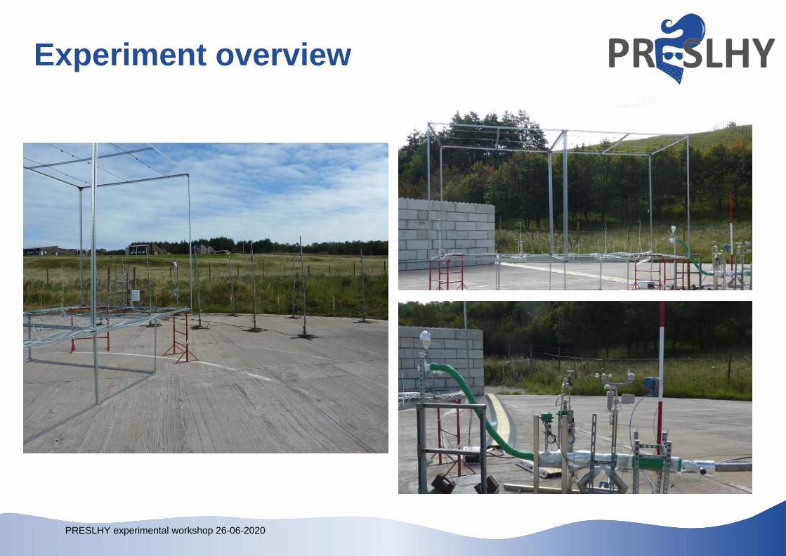
Aims The main objective of this series of experiments was to
investigate the propensity for rainout to occur when LH2 is released from elevated positions.
This included: vaporisation characterisation of the flow at the point of release dispersion of the gaseous hydrogen cloud (near and far field) capacity for these releases to form pools
PRESLHY experimental workshop 26-06-2020
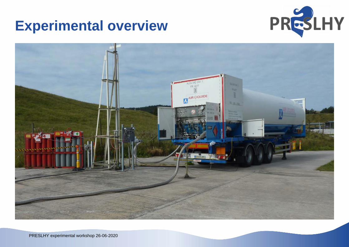
Experimental overview
PRESLHY experimental workshop 26-06-2020
Experiment overview
PRESLHY experimental workshop 26-06-2020
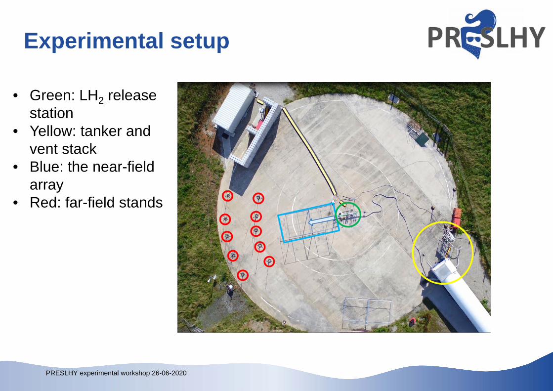
Experimental setup
• Green: LH2 release station
• Yellow: tanker and vent stack
• Blue: the near-field array
• Red: far-field stands
PRESLHY experimental workshop 26-06-2020
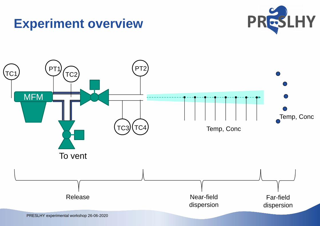
Experiment overview
PT1 PT2
TC4
TC2
MFM
TC3
To vent
TC1
Release Near-field dispersion
Far-field dispersion
Temp, Conc
Temp, Conc
PRESLHY experimental workshop 26-06-2020
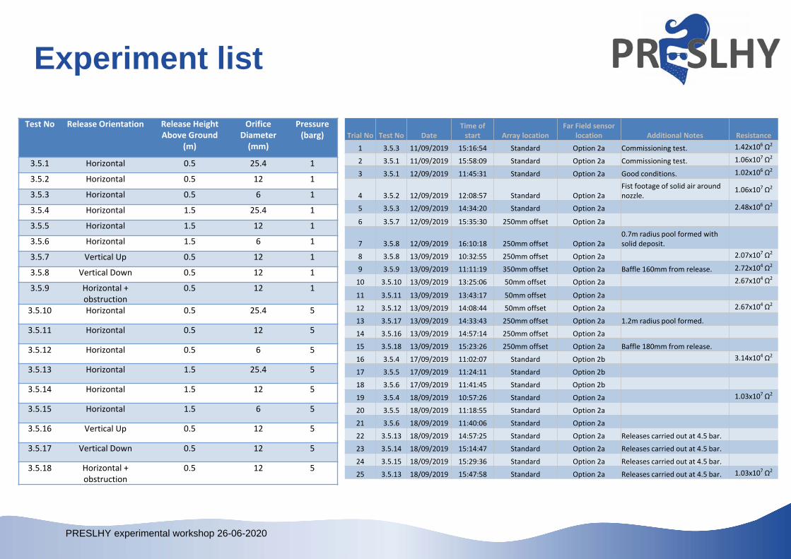
Experiment list
Trial No Test No Date Time of start Array location
Far Field sensor location Additional Notes Resistance
1 3.5.3 11/09/2019 15:16:54 Standard Option 2a Commissioning test. 1.42x10⁶ Ω2
2 3.5.1 11/09/2019 15:58:09 Standard Option 2a Commissioning test. 1.06x10⁷ Ω2
3 3.5.1 12/09/2019 11:45:31 Standard Option 2a Good conditions. 1.02x10⁶ Ω2
4 3.5.2 12/09/2019 12:08:57 Standard Option 2aFist footage of solid air around nozzle.
1.06x10⁷ Ω2
5 3.5.3 12/09/2019 14:34:20 Standard Option 2a 2.48x10⁶ Ω2
6 3.5.7 12/09/2019 15:35:30 250mm offset Option 2a
7 3.5.8 12/09/2019 16:10:18 250mm offset Option 2a0.7m radius pool formed with solid deposit.
8 3.5.8 13/09/2019 10:32:55 250mm offset Option 2a 2.07x10⁷ Ω2
9 3.5.9 13/09/2019 11:11:19 350mm offset Option 2a Baffle 160mm from release. 2.72x10⁴ Ω2
10 3.5.10 13/09/2019 13:25:06 50mm offset Option 2a 2.67x10⁴ Ω2
11 3.5.11 13/09/2019 13:43:17 50mm offset Option 2a
12 3.5.12 13/09/2019 14:08:44 50mm offset Option 2a 2.67x10⁴ Ω2
13 3.5.17 13/09/2019 14:33:43 250mm offset Option 2a 1.2m radius pool formed.
14 3.5.16 13/09/2019 14:57:14 250mm offset Option 2a
15 3.5.18 13/09/2019 15:23:26 250mm offset Option 2a Baffle 180mm from release.
16 3.5.4 17/09/2019 11:02:07 Standard Option 2b 3.14x10⁴ Ω2
17 3.5.5 17/09/2019 11:24:11 Standard Option 2b
18 3.5.6 17/09/2019 11:41:45 Standard Option 2b
19 3.5.4 18/09/2019 10:57:26 Standard Option 2a 1.03x10⁷ Ω2
20 3.5.5 18/09/2019 11:18:55 Standard Option 2a
21 3.5.6 18/09/2019 11:40:06 Standard Option 2a
22 3.5.13 18/09/2019 14:57:25 Standard Option 2a Releases carried out at 4.5 bar.
23 3.5.14 18/09/2019 15:14:47 Standard Option 2a Releases carried out at 4.5 bar.
24 3.5.15 18/09/2019 15:29:36 Standard Option 2a Releases carried out at 4.5 bar.
25 3.5.13 18/09/2019 15:47:58 Standard Option 2a Releases carried out at 4.5 bar. 1.03x10⁷ Ω2
Test No Release Orientation Release Height Above Ground
(m)
Orifice Diameter (mm)
Pressure (barg)
3.5.1 Horizontal 0.5 25.4 1
3.5.2 Horizontal 0.5 12 1
3.5.3 Horizontal 0.5 6 1
3.5.4 Horizontal 1.5 25.4 1
3.5.5 Horizontal 1.5 12 1
3.5.6 Horizontal 1.5 6 1
3.5.7 Vertical Up 0.5 12 1
3.5.8 Vertical Down 0.5 12 1
3.5.9 Horizontal + obstruction
0.5 12 1
3.5.10 Horizontal 0.5 25.4 5
3.5.11 Horizontal 0.5 12 5
3.5.12 Horizontal 0.5 6 5
3.5.13 Horizontal 1.5 25.4 5
3.5.14 Horizontal 1.5 12 5
3.5.15 Horizontal 1.5 6 5
3.5.16 Vertical Up 0.5 12 5
3.5.17 Vertical Down 0.5 12 5
3.5.18 Horizontal + obstruction
0.5 12 5
PRESLHY experimental workshop 26-06-2020
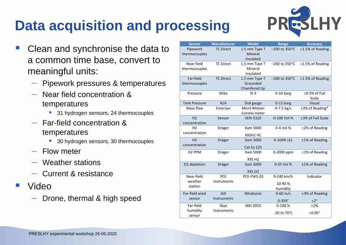
Data acquisition and processing Clean and synchronise the data to
a common time base, convert to meaningful units: Pipework pressures & temperatures Near field concentration &
temperatures 31 hydrogen sensors, 24 thermocouples
Far-field concentration & temperatures 30 hydrogen sensors, 30 thermocouples
Flow meter Weather stations Current & resistance
Video Drone, thermal & high speed
Sensor Manufacturer Model Range AccuracyPipework
thermocouplesTC Direct 1.5 mm Type T
Mineral insulated
–200 to 350°C ±1.5% of Reading
Near‐field thermocouples
TC Direct 1.5 mm Type T Mineral insulated
–200 to 350°C ±1.5% of Reading
Far‐field thermocouples
TC Direct 1.5 mm Type T Grounded
Chamfered tip
–200 to 350°C ±1.5% of Reading
Pressure Wika IS‐3 0‐10 barg ±0.5% of Full Scale
Tank Pressure N/A Dial gauge 0‐15 barg Visual Mass flow Emerson Micro Motion
Coriolis meter0‐7.5 kg/s ±3% of Reading*
H2 concentration
Xensor XEN‐5320 0‐100 Vol % ±3% of Full Scale
H2 concentration
Dräger Xam 5000
XXSH2 HC
0‐4 Vol % ±2% of Reading
H2 concentration
Dräger Xam 5000
Cat‐Ex 125
0‐100% LEL ±1% of Reading
H2 PPM Dräger Xam 5000
XXS H2
0‐2000 ppm ±1% of Reading
O2 depletion Dräger Xam 5000
XXS O2
0‐25 Vol % ±1% of Reading
Near‐field weather station
PCE Instruments
PCE‐FWS‐20 0‐240 km/h
10‐90 % humidity
Indicator
Far‐field wind sensor
Gill Instruments
Windsonic 0‐60 m/s
0‐359°
±3% of Reading
±2°Far‐field humidity sensor
Skye Instruments
SKH 2053 0‐100 %
‐20 to 70°C
±2%
±0.05°
PRESLHY experimental workshop 26-06-2020
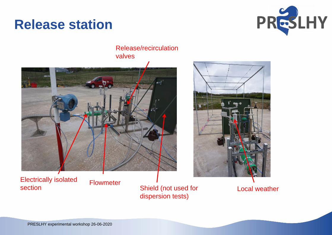
Release station
Electrically isolated section
Flowmeter
Release/recirculation valves
Local weatherShield (not used for dispersion tests)
PRESLHY experimental workshop 26-06-2020
Experiment procedure Condition LH2 in tank
Flatten the fluid by venting gaseous H2 from the tanker Allow LH2 into the heat exchanger until the desired pressure is
reached Purge the pipework with N2 then warm H2
Initiate recording and prepare triggers Implement safety zones and open manual release valve Operate remote release valves Stop release and complete post-test tasks
PRESLHY experimental workshop 26-06-2020
Release system measurements Temperatures
“Warm” temperatures logged as CJC compensated temperature “Cold” temperatures (pipework, near-field array) logged as
voltage Voltage converted to temperature using cold junction
measurement and lookup table Thermocouples in pipework not indicating BP for LH2
Post-test investigation of thermocouples conducted using LN2: low temperature error found on thermocouples in pipework (TC1-5
only), error increases as temperature decreases, and investigation reported in D3.6.
PRESLHY experimental workshop 26-06-2020
Release system measurements
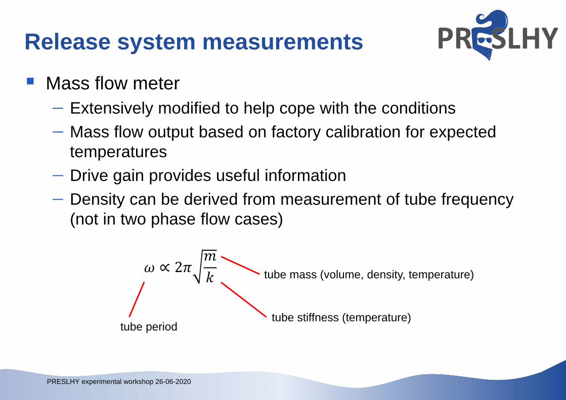
Mass flow meter Extensively modified to help cope with the conditions Mass flow output based on factory calibration for expected
temperatures Drive gain provides useful information Density can be derived from measurement of tube frequency
(not in two phase flow cases)
∝ 2 tube mass (volume, density, temperature)
tube stiffness (temperature) tube period
PRESLHY experimental workshop 26-06-2020
Release system measurements How much LH2 flows out? What state is it in?
PRESLHY experimental workshop 26-06-2020
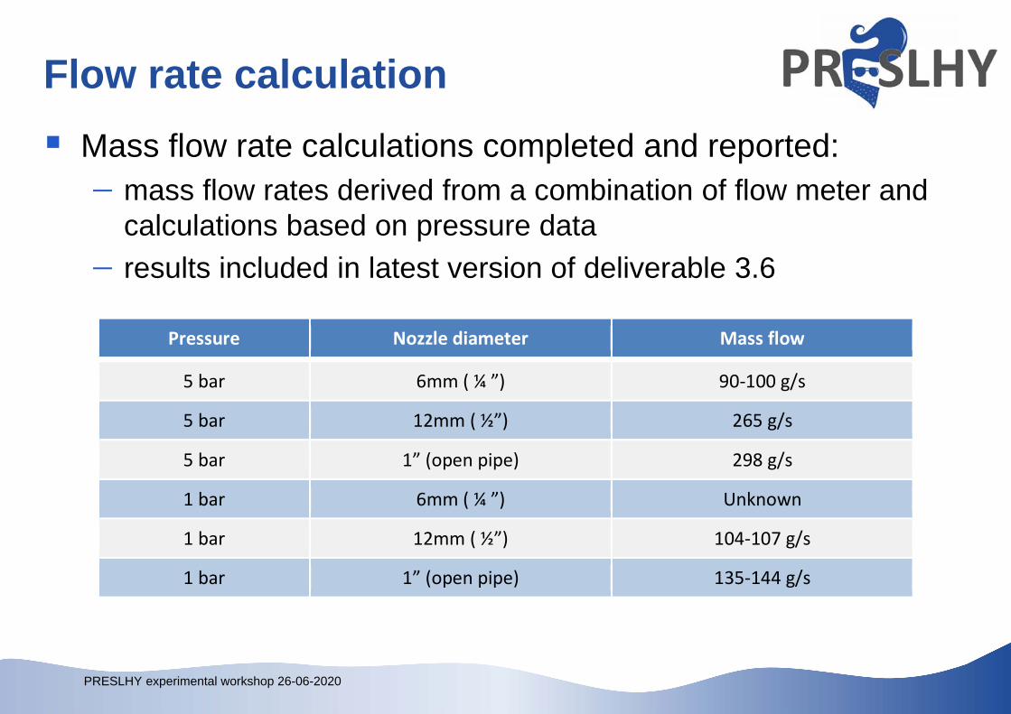
Flow rate calculation Mass flow rate calculations completed and reported:
mass flow rates derived from a combination of flow meter and calculations based on pressure data
results included in latest version of deliverable 3.6
Pressure Nozzle diameter Mass flow
5 bar 6mm ( ¼ ”) 90‐100 g/s
5 bar 12mm ( ½”) 265 g/s
5 bar 1” (open pipe) 298 g/s
1 bar 6mm ( ¼ ”) Unknown
1 bar 12mm ( ½”) 104‐107 g/s
1 bar 1” (open pipe) 135‐144 g/s
PRESLHY experimental workshop 26-06-2020
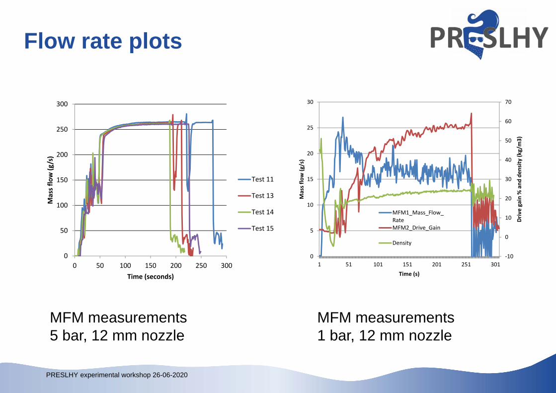
Flow rate plots
0
50
100
150
200
250
300
0 50 100 150 200 250 300
Mass flo
w (g
/s)
Time (seconds)
Test 11
Test 13
Test 14
Test 15
MFM measurements5 bar, 12 mm nozzle
‐10
0
10
20
30
40
50
60
70
0
5
10
15
20
25
30
1 51 101 151 201 251 301
Driv
e gain % and
den
sity (k
g/m3)
Mass flow (g
/s)
Time (s)
MFM1_Mass_Flow_RateMFM2_Drive_Gain
Density
MFM measurements1 bar, 12 mm nozzle
PRESLHY experimental workshop 26-06-2020
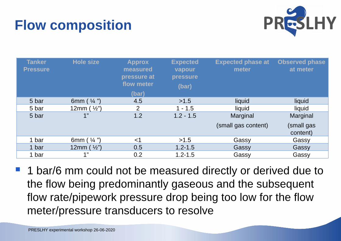
Flow composition
Tanker Pressure
Hole size Approx measured
pressure at flow meter
(bar)
Expected vapour
pressure(bar)
Expected phase at meter
Observed phase at meter
5 bar 6mm ( ¼ ”) 4.5 >1.5 liquid liquid5 bar 12mm ( ½”) 2 1 - 1.5 liquid liquid5 bar 1” 1.2 1.2 - 1.5 Marginal
(small gas content)Marginal
(small gas content)
1 bar 6mm ( ¼ ”) <1 >1.5 Gassy Gassy1 bar 12mm ( ½”) 0.5 1.2-1.5 Gassy Gassy1 bar 1” 0.2 1.2-1.5 Gassy Gassy
1 bar/6 mm could not be measured directly or derived due to the flow being predominantly gaseous and the subsequent flow rate/pipework pressure drop being too low for the flow meter/pressure transducers to resolve
PRESLHY experimental workshop 26-06-2020
Rainout/outflow summary Rainout did not occur during the established flow of these releases, some
seen after valve closure (probably liquid air) Temperatures did not reach H2 rainout levels at the vent stack Pools can form with vertically downwards releases Flow meter is only effective at higher pressures and smaller nozzle sizes
(i.e. void fraction is low) Heat losses due to flow meter and additional pipework reduced
effectiveness of meter (caused 2 phase flow) PRESLHY data can be used to estimate the flow rate in previous HSE
experiments at approximately 135 g/s
PRESLHY experimental workshop 26-06-2020
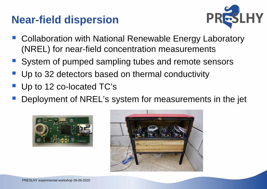
Near-field dispersion Collaboration with National Renewable Energy Laboratory
(NREL) for near-field concentration measurements System of pumped sampling tubes and remote sensors Up to 32 detectors based on thermal conductivity Up to 12 co-located TC’s Deployment of NREL’s system for measurements in the jet
PRESLHY experimental workshop 26-06-2020
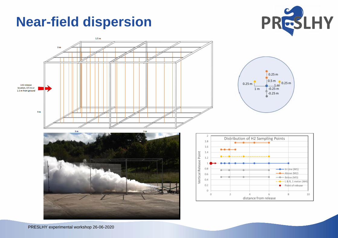
Near-field dispersion
PRESLHY experimental workshop 26-06-2020
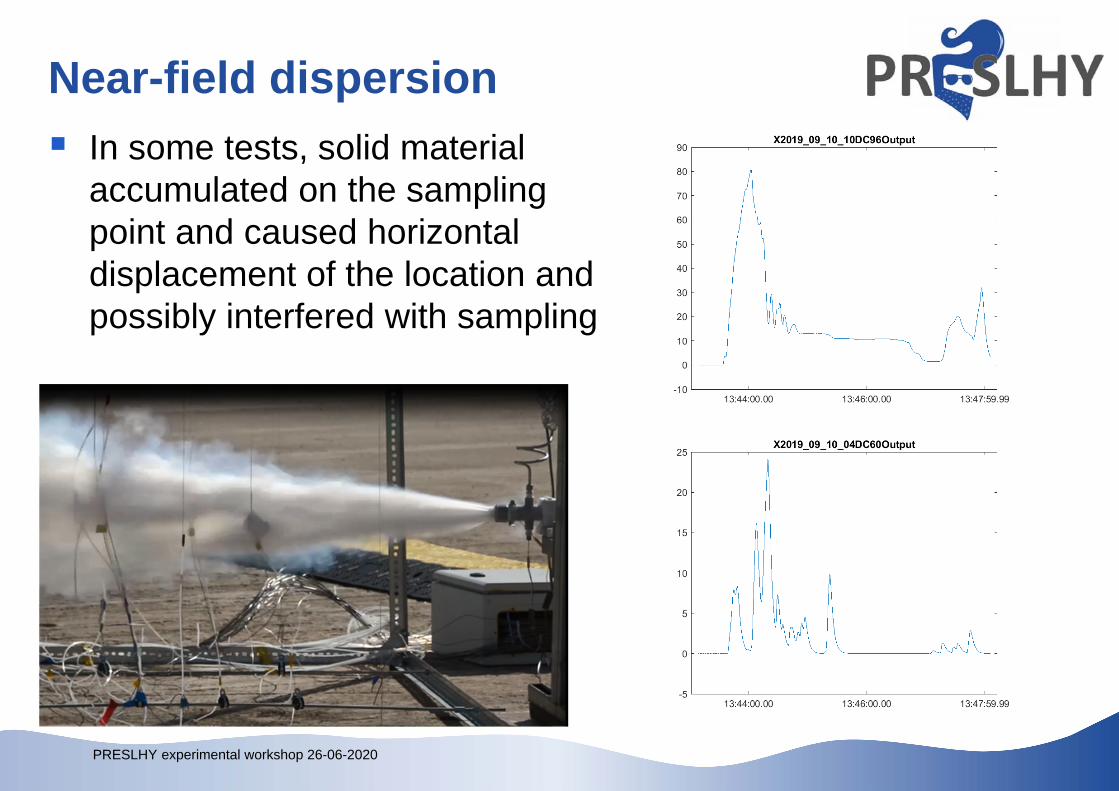
Near-field dispersion In some tests, solid material
accumulated on the sampling point and caused horizontal displacement of the location and possibly interfered with sampling
PRESLHY experimental workshop 26-06-2020
Near-field dispersion
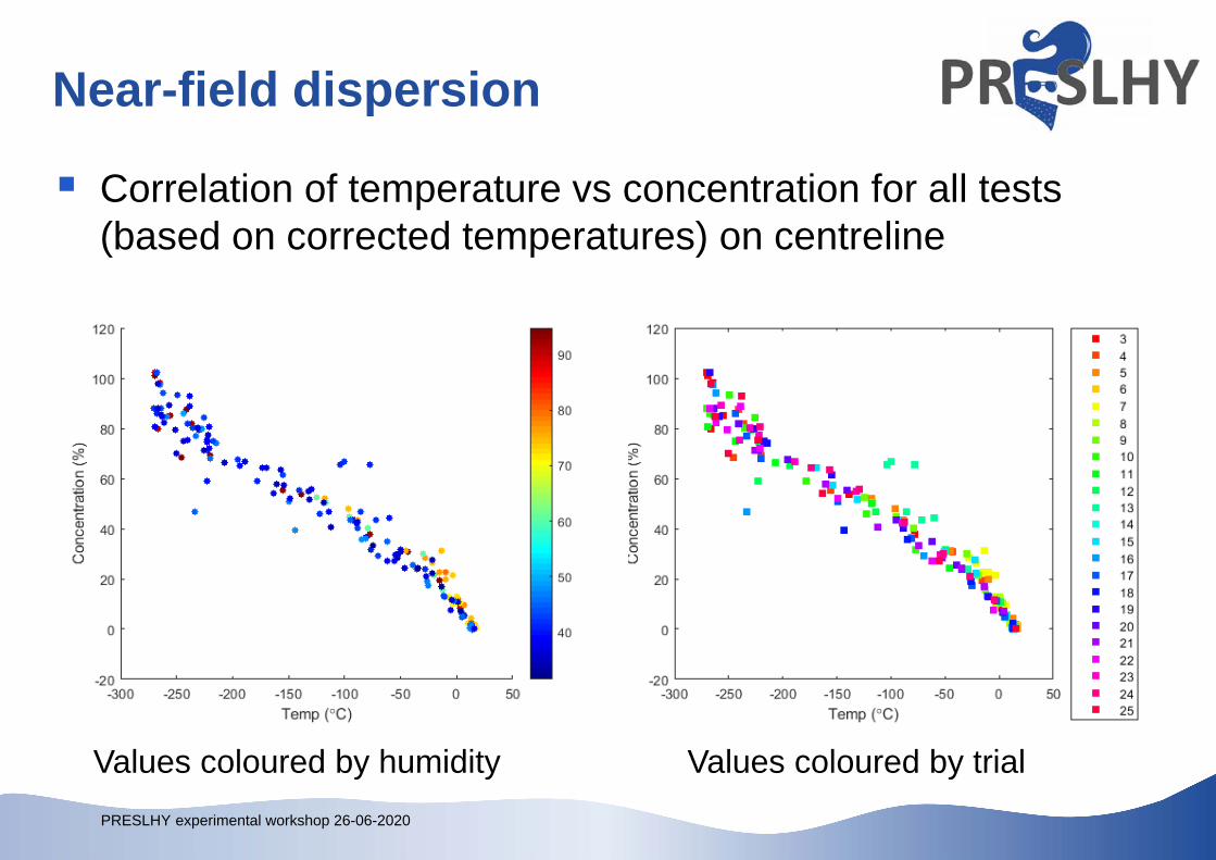
Correlation of temperature vs concentration for all tests (based on corrected temperatures) on centreline
Values coloured by humidity Values coloured by trial
PRESLHY experimental workshop 26-06-2020
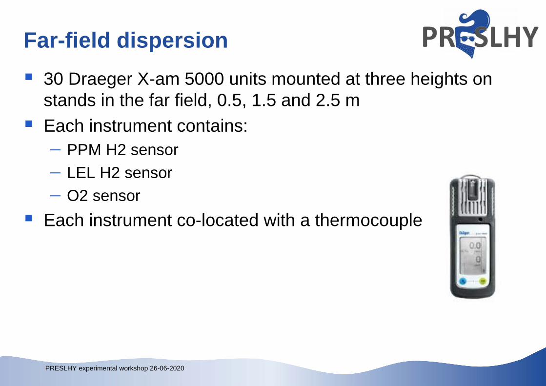
Far-field dispersion 30 Draeger X-am 5000 units mounted at three heights on
stands in the far field, 0.5, 1.5 and 2.5 m Each instrument contains:
PPM H2 sensor LEL H2 sensor O2 sensor
Each instrument co-located with a thermocouple
PRESLHY experimental workshop 26-06-2020
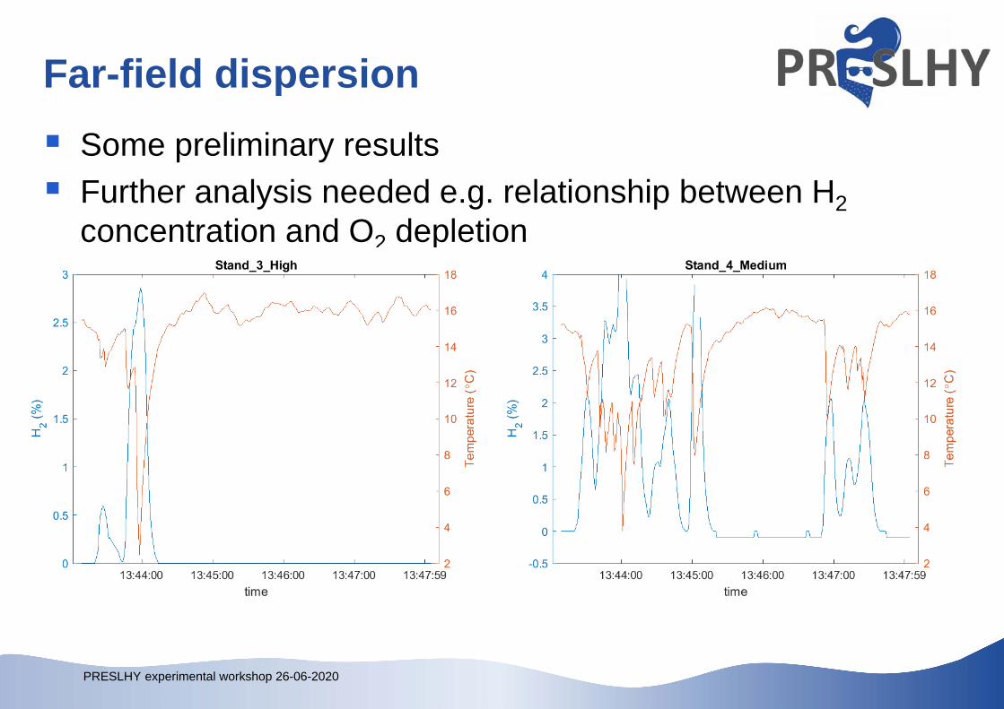
Far-field dispersion Some preliminary results Further analysis needed e.g. relationship between H2
concentration and O2 depletion
PRESLHY experimental workshop 26-06-2020
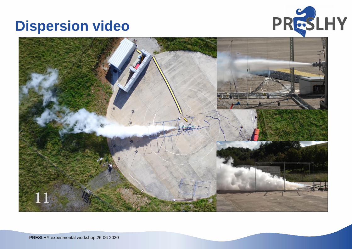
Dispersion video
PRESLHY experimental workshop 26-06-2020
Dispersion summary Solid deposits formed around the release point and on impingements
with 6/12 mm nozzles, thought to be solidified air Higher pressures and larger nozzles increase the average hydrogen
concentration in the near-field region, in spite of the mass flow meter under-predicting mass flow rates with certain initial conditions
Transient ignitable pockets (average H2 concentration > LEL) were measured at 14 m distance from LH2 releases through 12 mm holes or larger
Following the initial region, approximately 1.5 m for the 1 bar releases and 3 to 6 m for the 5 bar releases, the dispersion of the hydrogen cloud is heavily dependent of the wind, including transient localised gusts
PRESLHY experimental workshop 26-06-2020
AcknowledgementsThis project has received funding from the Fuel Cells and Hydrogen 2 Joint Undertaking under the European Union’s Horizon 2020 research and innovation programme under grant agreement No 779613. The HSE work programme acknowledges funding from its sponsors Shell, Lloyd’s Register Foundation and Equinor and instrumentation provided by NREL and Dräger.


