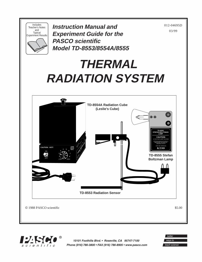
Instruction Manual andExperiment Guide for thePASCO scientificModel TD-8553/8554A/8555
IncludesTeacher's Notes
andTypical
Experiment Results
2
Thermal Radiation 012-04695D
CAUTIONRISK OF ELECTRIC SHOCK
DO NOT OPEN
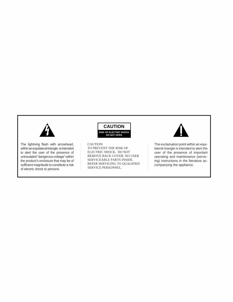
The lightning flash with arrowhead,within an equilateral triangle, is intendedto alert the user of the presence ofuninsulated “dangerous voltage” withinthe product’s enclosure that may be ofsufficient magnitude to constitute a riskof electric shock to persons.
CAUTION:TO PREVENT THE RISK OFELECTRIC SHOCK, DO NOTREMOVE BACK COVER. NO USERSERVICEABLE PARTS INSIDE.REFER SERVICING TO QUALIFIEDSERVICE PERSONNEL.
The exclamation point within an equi-lateral triangle is intended to alert theuser of the presence of importantoperating and maintenance (servic-ing) instructions in the literature ac-companying the appliance.
Technical Support ................................................................ Inside Back Cover
Thermal Radiation System 012-04695D
ii
Copyright Notice
The PASCO scientific Model TD 8553/8554A/8555 Thermal Radiation System manual iscopyrighted and all rights reserved. However, permis-sion is granted to non-profit educational institutions forreproduction of any part of the manual providing thereproductions are used only for their laboratories andare not sold for profit. Reproduction under any othercircumstances, without the written consent of PASCOscientific, is prohibited.
Limited Warranty
PASCO scientific warrants the product to be free fromdefects in materials and workmanship for a period ofone year from the date of shipment to the customer.PASCO will repair or replace at its option any part ofthe product which is deemed to be defective in materialor workmanship. The warranty does not cover damageto the product caused by abuse or improper use.Determination of whether a product failure is the resultof a manufacturing defect or improper use by thecustomer shall be made solely by PASCO scientific.Responsibility for the return of equipment for warrantyrepair belongs to the customer. Equipment must beproperly packed to prevent damage and shipped post-age or freight prepaid. (Damage caused by improperpacking of the equipment for return shipment will notbe covered by the warranty.) Shipping costs for return-ing the equipment after repair will be paid by PASCOscientific.
Copyright, Warranty, and Equipment Return
Please—Feel free to duplicate this manualsubject to the copyright restrictions below.
Equipment Return
Should the product have to be returned to PASCOscientific for any reason, notify PASCO scientific byletter, phone, or fax BEFORE returning the product.Upon notification, the return authorization and ship-ping instructions will be promptly issued.
ä NOTE: NO EQUIPMENT WILL BEACCEPTED FOR RETURN WITHOUT ANAUTHORIZATION FROM PASCO.
When returning equipment for repair, the units must bepacked properly. Carriers will not accept responsibilityfor damage caused by improper packing. To be certainthe unit will not be damaged in shipment, observe thefollowing rules:
➀ The packing carton must be strong enough for theitem shipped.
➁ Make certain there are at least two inches of pack-ing material between any point on the apparatus andthe inside walls of the carton.
➂ Make certain that the packing material cannot shiftin the box or become compressed, allowing theinstrument come in contact with the packing carton.
The PASCO Thermal Radiation System includes threeitems: the TD-8553 Radiation Sensor, the TD-8554ARadiation Cube (Leslie's Cube), and the TD-8555Stefan-Boltzmann Lamp. This manual containsoperating instructions for each of these items plusinstructions and worksheets for the following fourexperiments:
① Introduction to Thermal Radiation,
② Inverse Square Law,
③ Stefan-Boltzmann Law* (at high temperatures),
④ Stefan-Boltzmann Law* (at low temperatures).
* The Stefan-Boltzmann law states that the radiantenergy per unit area is proportional to the fourthpower of the temperature of the radiating surface.
In addition to the equipment in the radiation system,several standard laboratory items, such as powersupplies and meters are needed for most experiments.Check the experiment section of this manual forinformation on required equipment.
If you don't have all the items of the radiation system,read through the operating instructions for the equip-ment you do have, then check the experiment sectionto determine which of the experiments you can per-form. (A radiation sensor is required for all theexperiments.)
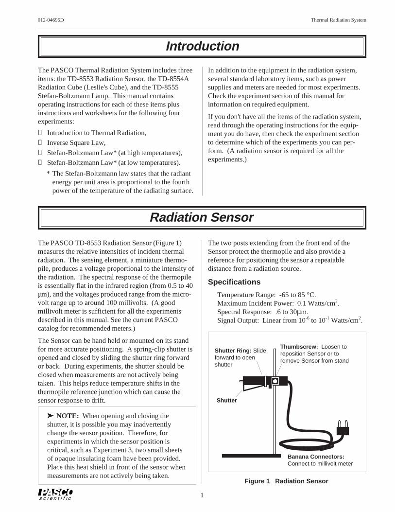
The two posts extending from the front end of theSensor protect the thermopile and also provide areference for positioning the sensor a repeatabledistance from a radiation source.
Specifications
Temperature Range: -65 to 85 °C.Maximum Incident Power: 0.1 Watts/cm2.Spectral Response: .6 to 30µm.Signal Output: Linear from 10-6 to 10-1 Watts/cm2.
The PASCO TD-8553 Radiation Sensor (Figure 1)measures the relative intensities of incident thermalradiation. The sensing element, a miniature thermo-pile, produces a voltage proportional to the intensity ofthe radiation. The spectral response of the thermopileis essentially flat in the infrared region (from 0.5 to 40µm), and the voltages produced range from the micro-volt range up to around 100 millivolts. (A goodmillivolt meter is sufficient for all the experimentsdescribed in this manual. See the current PASCOcatalog for recommended meters.)
The Sensor can be hand held or mounted on its standfor more accurate positioning. A spring-clip shutter isopened and closed by sliding the shutter ring forwardor back. During experiments, the shutter should beclosed when measurements are not actively beingtaken. This helps reduce temperature shifts in thethermopile reference junction which can cause thesensor response to drift.
ä NOTE: When opening and closing theshutter, it is possible you may inadvertentlychange the sensor position. Therefore, forexperiments in which the sensor position iscritical, such as Experiment 3, two small sheetsof opaque insulating foam have been provided.Place this heat shield in front of the sensor whenmeasurements are not actively being taken.
Figure 1 Radiation Sensor
Banana Connectors:Connect to millivolt meter
Thumbscrew: Loosen toreposition Sensor or toremove Sensor from stand
Shutter
Shutter Ring: Slideforward to openshutter
2
Thermal Radiation System 012-04695D
Thermal Radiation Cube (Leslie’s Cube)
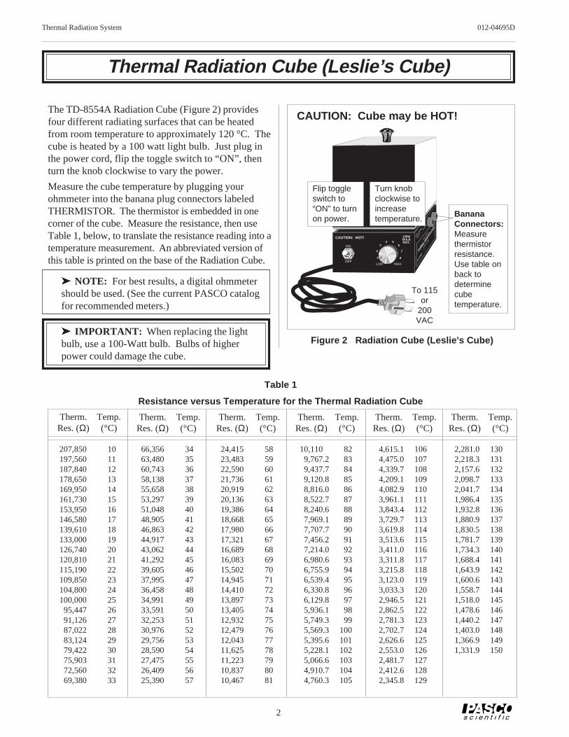
The TD-8554A Radiation Cube (Figure 2) providesfour different radiating surfaces that can be heatedfrom room temperature to approximately 120 °C. Thecube is heated by a 100 watt light bulb. Just plug inthe power cord, flip the toggle switch to “ON”, thenturn the knob clockwise to vary the power.
Measure the cube temperature by plugging yourohmmeter into the banana plug connectors labeledTHERMISTOR. The thermistor is embedded in onecorner of the cube. Measure the resistance, then useTable 1, below, to translate the resistance reading into atemperature measurement. An abbreviated version ofthis table is printed on the base of the Radiation Cube.
ä NOTE: For best results, a digital ohmmetershould be used. (See the current PASCO catalogfor recommended meters.)
ä IMPORTANT: When replacing the lightbulb, use a 100-Watt bulb. Bulbs of higherpower could damage the cube.
Resistance versus Temperature for the Thermal Radiation Cube
3
012-04695D Thermal Radiation System
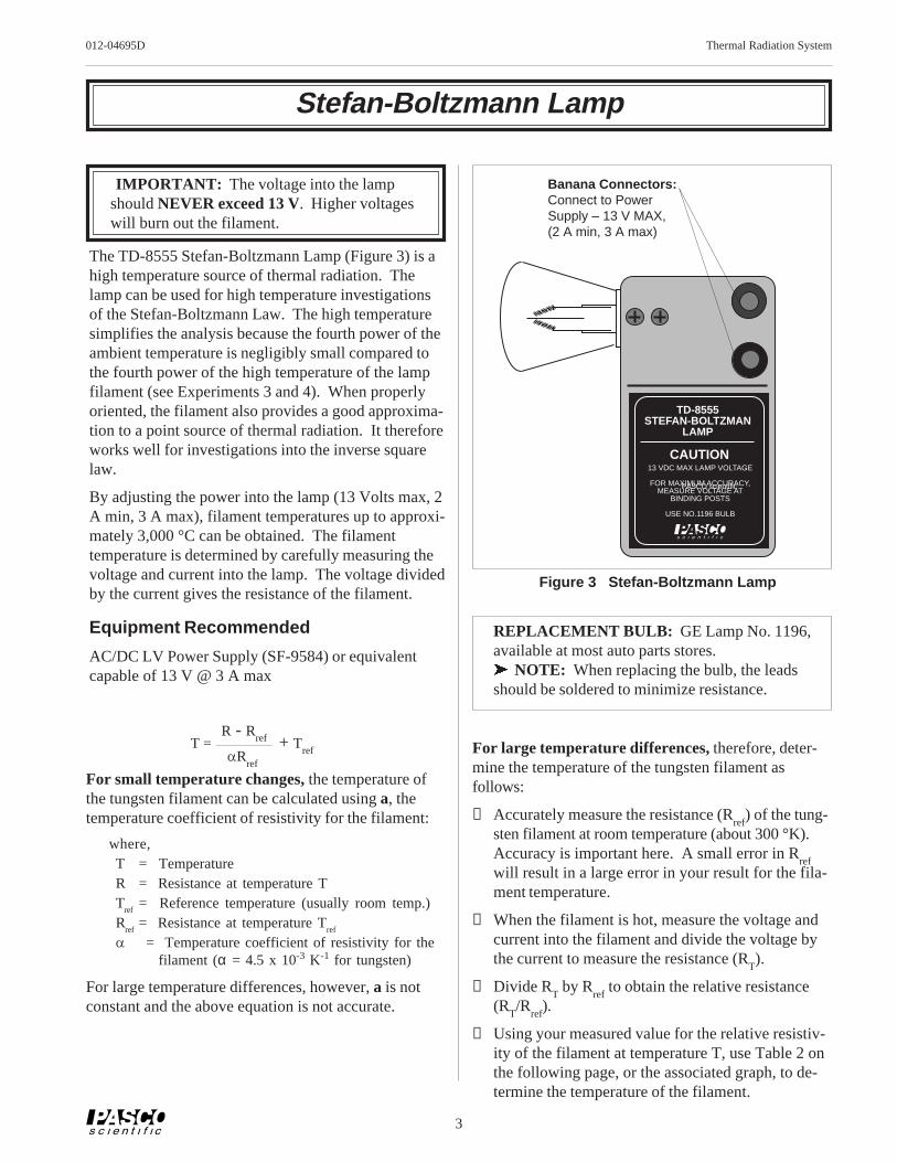
TD-8555STEFAN-BOLTZMAN
LAMP
CAUTION13 VDC MAX LAMP VOLTAGE
FOR MAXIMUM ACCURACY,MEASURE VOLTAGE AT
BINDING POSTS
USE NO.1196 BULB
Stefan-Boltzmann Lamp
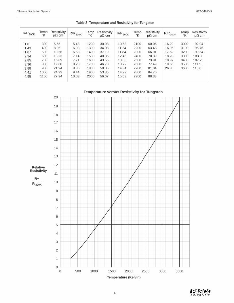
For large temperature differences, therefore, deter-mine the temperature of the tungsten filament asfollows:
① Accurately measure the resistance (Rref
) of the tung-sten filament at room temperature (about 300 °K).Accuracy is important here. A small error in R
refwill result in a large error in your result for the fila-ment temperature.
② When the filament is hot, measure the voltage andcurrent into the filament and divide the voltage bythe current to measure the resistance (R
T).
③ Divide RT by R
ref to obtain the relative resistance
(RT/R
ref).
④ Using your measured value for the relative resistiv-ity of the filament at temperature T, use Table 2 onthe following page, or the associated graph, to de-termine the temperature of the filament.
IMPORTANT: The voltage into the lampshould NEVER exceed 13 V. Higher voltageswill burn out the filament.
The TD-8555 Stefan-Boltzmann Lamp (Figure 3) is ahigh temperature source of thermal radiation. Thelamp can be used for high temperature investigationsof the Stefan-Boltzmann Law. The high temperaturesimplifies the analysis because the fourth power of theambient temperature is negligibly small compared tothe fourth power of the high temperature of the lampfilament (see Experiments 3 and 4). When properlyoriented, the filament also provides a good approxima-tion to a point source of thermal radiation. It thereforeworks well for investigations into the inverse squarelaw.
By adjusting the power into the lamp (13 Volts max, 2A min, 3 A max), filament temperatures up to approxi-mately 3,000 °C can be obtained. The filamenttemperature is determined by carefully measuring thevoltage and current into the lamp. The voltage dividedby the current gives the resistance of the filament.
Equipment Recommended
AC/DC LV Power Supply (SF-9584) or equivalentcapable of 13 V @ 3 A max
For small temperature changes, the temperature ofthe tungsten filament can be calculated using a, thetemperature coefficient of resistivity for the filament:
where,T = TemperatureR = Resistance at temperature TT
ref= Reference temperature (usually room temp.)
Rref
= Resistance at temperature Tref
a = Temperature coefficient of resistivity for thefilament (α = 4.5 x 10⁻³ K-1 for tungsten)
For large temperature differences, however, a is notconstant and the above equation is not accurate.
T = + Tref
R - Rref
aRref
REPLACEMENT BULB: GE Lamp No. 1196,available at most auto parts stores.ä NOTE: When replacing the bulb, the leadsshould be soldered to minimize resistance.
PASCO scientific
Banana Connectors:Connect to PowerSupply – 13 V MAX,(2 A min, 3 A max)
① If lab time is short, it's helpful to preheat the cube at a setting of 5.0 for 20 minutes beforethe laboratory period begins. (A very quick method is to preheat the cube at full powerfor 45 minutes, then use a small fan to reduce the temperature quickly as you lower thepower input. Just be sure that equilibrium is attained with the fan off.)
② Part 1 and 2 of this experiment can be performed simultaneously. Make the measure-ments in Part 2 while waiting for the Radiation Cube to reach thermal equilibrium at eachof the settings in Part 1.
③ When using the Radiation Sensor, always shield it from the hot object except for the fewseconds it takes to actually make the measurement. This prevents heating of the thermo-pile which will change the reference temperature and alter the reading.
Radiation Rates from Different Surfaces
Part 1
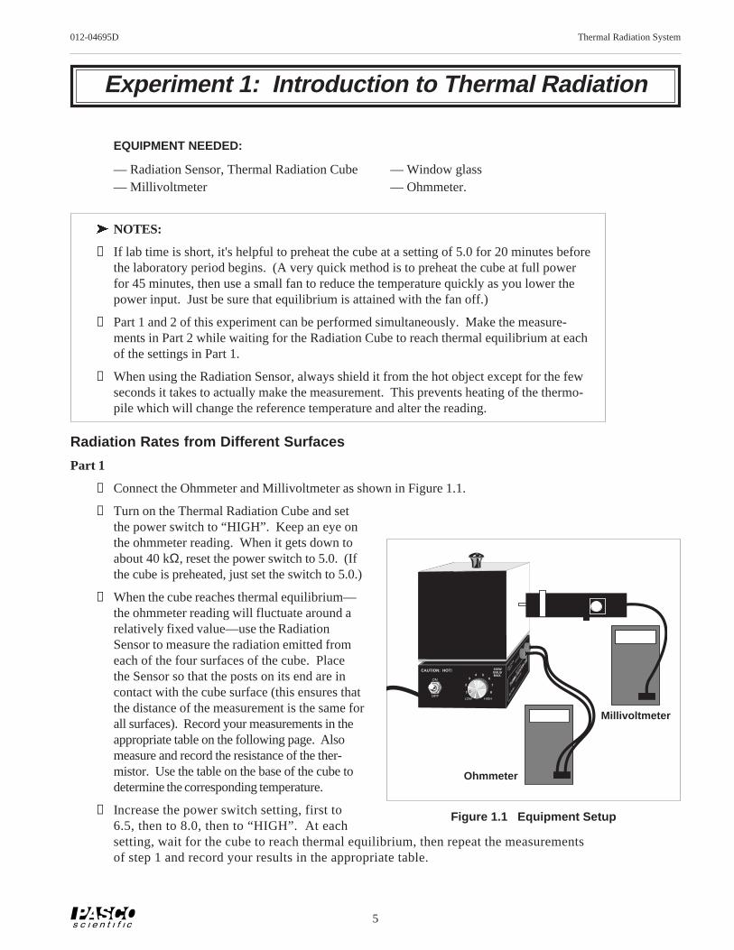
① Connect the Ohmmeter and Millivoltmeter as shown in Figure 1.1.
② Turn on the Thermal Radiation Cube and setthe power switch to “HIGH”. Keep an eye onthe ohmmeter reading. When it gets down toabout 40 kΩ, reset the power switch to 5.0. (Ifthe cube is preheated, just set the switch to 5.0.)
③ When the cube reaches thermal equilibrium—the ohmmeter reading will fluctuate around arelatively fixed value—use the RadiationSensor to measure the radiation emitted fromeach of the four surfaces of the cube. Placethe Sensor so that the posts on its end are incontact with the cube surface (this ensures thatthe distance of the measurement is the same forall surfaces). Record your measurements in theappropriate table on the following page. Alsomeasure and record the resistance of the ther-mistor. Use the table on the base of the cube todetermine the corresponding temperature.
④ Increase the power switch setting, first to6.5, then to 8.0, then to “HIGH”. At eachsetting, wait for the cube to reach thermal equilibrium, then repeat the measurementsof step 1 and record your results in the appropriate table.
1 2 3
4 5 6
7
8
LOW HIGH
CAUTION: HOT! CAUTIO
N
HOT!THERMIST
OR
Model TD
-8554A
(LESLI
E'S CU
BE)100WBULBMAX.
ON
OFF
Millivoltmeter
Ohmmeter
Figure 1.1 Equipment Setup
6
Thermal Radiation System 012-04695D
Part 2
Use the Radiation Sensor to examine the relative magnitudes of the radiation emitted fromvarious objects around the room. On a separate sheet of paper, make a table summarizing yourobservations. Make measurements that will help you to answer the questions listed below.
Absorption and Transmission of Thermal Radiation
① Place the Sensor approximately 5 cm from the black surface of the Radiation Cube and recordthe reading. Place a piece of window glass between the Sensor and the bulb. Does windowglass effectively block thermal radiation?
② Remove the lid from the Radiation Cube (or use the Stefan-Boltzmann Lamp) and repeat themeasurements of step 1, but using the bare bulb instead of the black surface. Repeat with othermaterials.
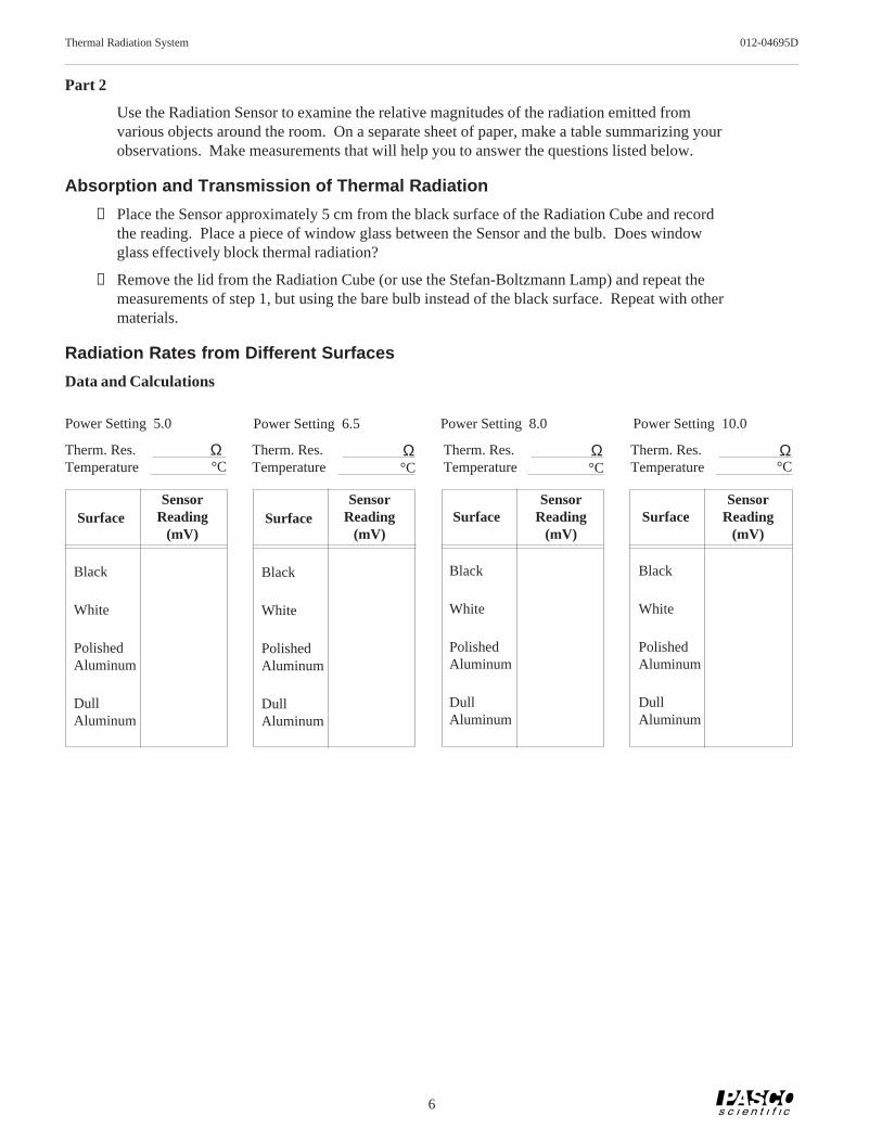
Radiation Rates from Different Surfaces
Data and Calculations
Therm. Res. Therm. Res.Temperature
Therm. Res.Temperature Temperature
Therm. Res.Temperature
Ω°C
Ω°C
SensorReading
(mV)
SensorReading
(mV)
SensorReading
(mV)
SensorReading
(mV)
Ω°C
Ω°C
Surface
Black
White
PolishedAluminum
DullAluminum
Surface
Black
White
PolishedAluminum
DullAluminum
Surface
Black
White
PolishedAluminum
DullAluminum
Surface
Black
White
PolishedAluminum
DullAluminum
Power Setting 5.0 Power Setting 6.5 Power Setting 8.0 Power Setting 10.0
7
012-04695D Thermal Radiation System
Questions (Part 1)
① List the surfaces of the Radiation Cube in order of the amount of radiation emitted. Is the orderindependent of temperature?
② It is a general rule that good absorbers of radiation are also good emitters. Are your measure-ments consistent with this rule? Explain.
Questions (Part 2)
① Do different objects, at approximately the same temperature, emit different amounts of radiation?
② Can you find materials in your room that block thermal radiation? Can you find materials thatdon't block thermal radiation? (For example, do your clothes effectively block the thermalradiation emitted from your body?)
Absorption and Transmission of Thermal Radiation
Questions
① What do your results suggest about the phenomenon of heat loss through windows?
② What do your results suggest about the Greenhouse Effect?
8
Thermal Radiation System 012-04695D
Notes
9
012-04695D Thermal Radiation System
Experiment 2: Inverse Square Law
EQUIPMENT NEEDED:
— Radiation Sensor— Stefan-Boltzmann Lamp, Millivoltmeter— Power Supply (12 VDC; 3 A), meter stick.
Align axes of filament and Sensor
Top View
X
Millivoltmeter Meter Stick
Align zero-point of meter stickwith center of filament
Power Supply(13 V MAX!)
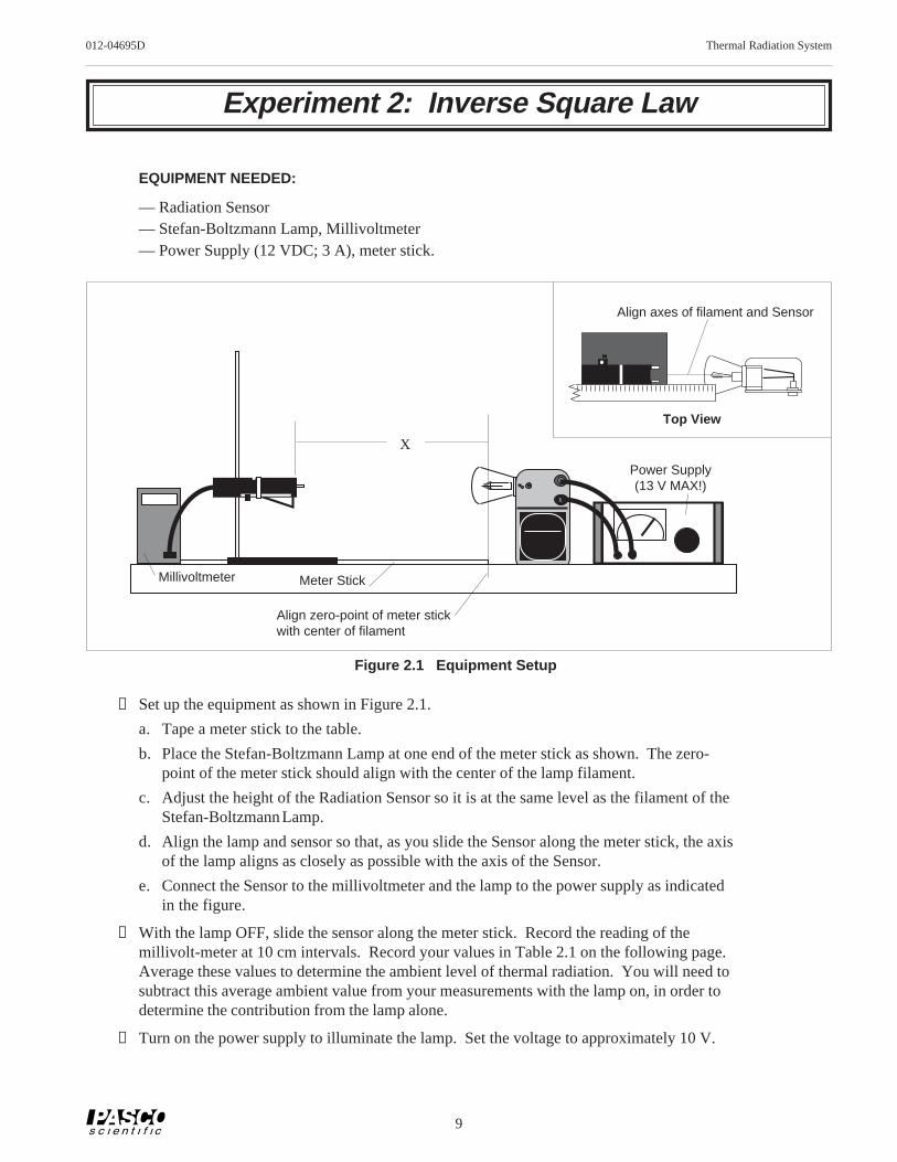
Figure 2.1 Equipment Setup
① Set up the equipment as shown in Figure 2.1.
a. Tape a meter stick to the table.
b. Place the Stefan-Boltzmann Lamp at one end of the meter stick as shown. The zero-point of the meter stick should align with the center of the lamp filament.
c. Adjust the height of the Radiation Sensor so it is at the same level as the filament of theStefan-Boltzmann Lamp.
d. Align the lamp and sensor so that, as you slide the Sensor along the meter stick, the axisof the lamp aligns as closely as possible with the axis of the Sensor.
e. Connect the Sensor to the millivoltmeter and the lamp to the power supply as indicatedin the figure.
② With the lamp OFF, slide the sensor along the meter stick. Record the reading of themillivolt-meter at 10 cm intervals. Record your values in Table 2.1 on the following page.Average these values to determine the ambient level of thermal radiation. You will need tosubtract this average ambient value from your measurements with the lamp on, in order todetermine the contribution from the lamp alone.
③ Turn on the power supply to illuminate the lamp. Set the voltage to approximately 10 V.
10
Thermal Radiation System 012-04695D
X Rad 1/X2 Rad - Ambient(cm) (mV) (cm-2) (mV)
2.5
3.0
3.5
4.0
4.5
5.0
6.0
7.0
8.0
9.0
10.0
12.0
14.0
16.0
18.0
20.0
25.0
30.0
35.0
40.0
45.0
50.0
60.0
70.0
80.0
90.0
100.0
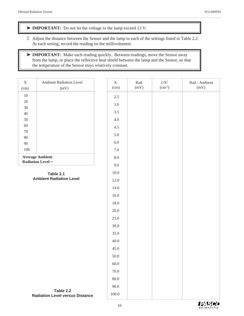
ä IMPORTANT: Do not let the voltage to the lamp exceed 13 V.
④ Adjust the distance between the Sensor and the lamp to each of the settings listed in Table 2.2.At each setting, record the reading on the millivoltmeter.
ä IMPORTANT: Make each reading quickly. Between readings, move the Sensor awayfrom the lamp, or place the reflective heat shield between the lamp and the Sensor, so thatthe temperature of the Sensor stays relatively constant.
Table 2.2Radiation Level versus Distance
X Ambient Radiation Level
(cm) (mV)
10
20
30
40
50
60
70
80
90
100
Table 2.1Ambient Radiation Level
Average AmbientRadiation Level =
11
012-04695D Thermal Radiation System
Calculations
① For each value of X, calculate 1/X2. Enter your results in Table 2.2.
② Subtract the Average Ambient Radiation Level from each of your Rad measurements inTable 2.2. Enter your results in the table.
③ On a separate sheet of paper, make a graph of Radiation Level versus Distance from Source,using columns one and four from Table 2.2. Let the radiation level be the dependent (y) axis.
④ If your graph from part 3 is not linear, make a graph of Radiation Level versus 1/X2, usingcolumns three and four from table 2.2.
Questions
① Which of the two graphs is more linear? Is it linear over the entire range of measurements?
② The inverse square law states that the radiant energy per unit area emitted by a point sourceof radiation decreases as the square of the distance from the source to the point of detection.Does your data support this assertion?
③ Is the Stefan-Boltzmann Lamp truly a point source of radiation? If not, how might thisaffect your results? Do you see such an effect in the data you have taken?
12
Thermal Radiation System 012-04695D
Notes
13
012-04695D Thermal Radiation System
Experiment 3: Stefan-Boltzmann Law (high temperature)
The Stefan-Boltzmann Law relates R, the power per unit area radiated by an object, to T, theabsolute temperature of the object. The equation is:
R = σ T4 ; σ =5.6703 x 10 –8 W
m 2K4
In this experiment, you will make relative measurements of the power per unit area emittedfrom a hot object, namely the Stefan-Boltzmann Lamp, at various temperatures. From yourdata you will be able to test whether the radiated power is really proportional to the fourthpower of the temperature.
Most of the thermal energy emitted by the lamp comes from the filament of the lamp. Thefilament temperature can be determined using the procedure given on pages 3 and 4 of thismanual.
– ++–
6 cm
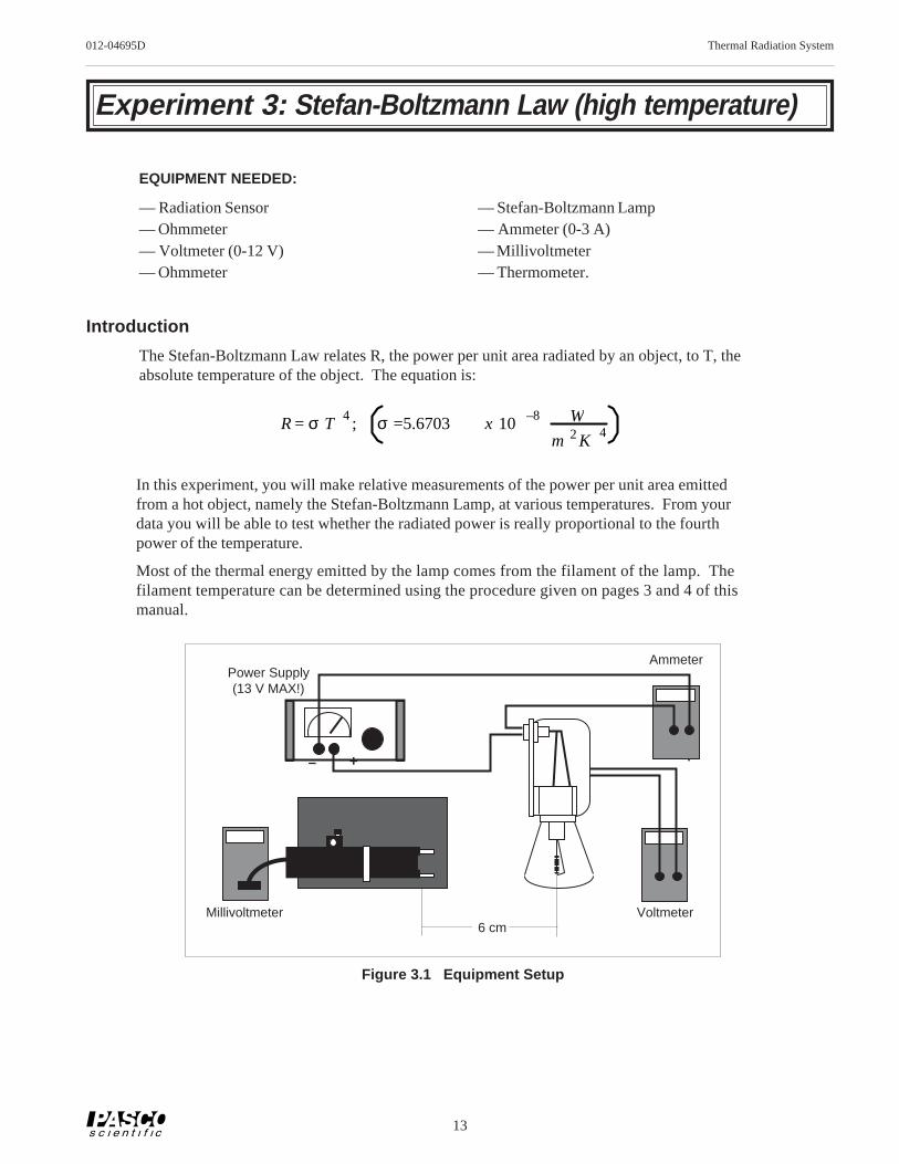
Figure 3.1 Equipment Setup
Voltmeter
Ammeter
Millivoltmeter
Power Supply(13 V MAX!)
14
Thermal Radiation System 012-04695D
Procedure
ä IMPORTANT: The voltage into the lamp should NEVER exceed 13 V. Higher voltageswill burn out the filament.
① BEFORE TURNING ON THE LAMP , measure Tref
, the room temperature in degreesKelvin, (K=°C + 273) and R
ref , the resistance of the filament of the Stefan-Boltzmann Lamp
at room temperature. Enter your results in the spaces on the following page.
② Set up the equipment as shown in Figure 3.1. The voltmeter should be connected directly tothe binding posts of the Stefan-Boltzmann Lamp. The Sensor should be at the same height asthe filament, with the front face of the Sensor approximately 6 cm away from the filament.The entrance angle of the thermopile should include no close objects other than the lamp.
③ Turn on the power supply. Set the voltage, V, to each of the settings listed in Table 3.1 onthe following page. At each voltage setting, record I, the ammeter reading, and Rad, thereading on the millivoltmeter.
ä IMPORTANT: Make each Sensor reading quickly. Between readings, place both sheetsof insulating foam between the lamp and the Sensor, with the silvered surface facing thelamp, so that the temperature of the Sensor stays relatively constant.
15
012-04695D Thermal Radiation System
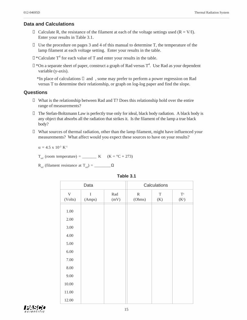
Data and Calculations
① Calculate R, the resistance of the filament at each of the voltage settings used (R = V/I).Enter your results in Table 3.1.
② Use the procedure on pages 3 and 4 of this manual to determine T, the temperature of thelamp filament at each voltage setting. Enter your results in the table.
③*Calculate T4 for each value of T and enter your results in the table.
④*On a separate sheet of paper, construct a graph of Rad versus T4. Use Rad as your dependentvariable (y-axis).
*In place of calculations ① and , some may prefer to perform a power regression on Radversus T to determine their relationship, or graph on log-log paper and find the slope.
Questions
① What is the relationship between Rad and T? Does this relationship hold over the entirerange of measurements?
② The Stefan-Boltzmann Law is perfectly true only for ideal, black body radiation. A black body isany object that absorbs all the radiation that strikes it. Is the filament of the lamp a true blackbody?
③ What sources of thermal radiation, other than the lamp filament, might have influenced yourmeasurements? What affect would you expect these sources to have on your results?
a = 4.5 x 10⁻³ K-1
Tref
(room temperature) = _______ K (K = °C + 273)
Rref
(filament resistance at Tref
) = ________Ω
V I Rad R T T4
(Volts) (Amps) (mV) (Ohms) (K) (K4)
1.00
2.00
3.00
4.00
5.00
6.00
7.00
8.00
9.00
10.00
11.00
12.00
Table 3.1
Data Calculations
16
Thermal Radiation System 012-04695D
Notes
17
012-04695D Thermal Radiation System
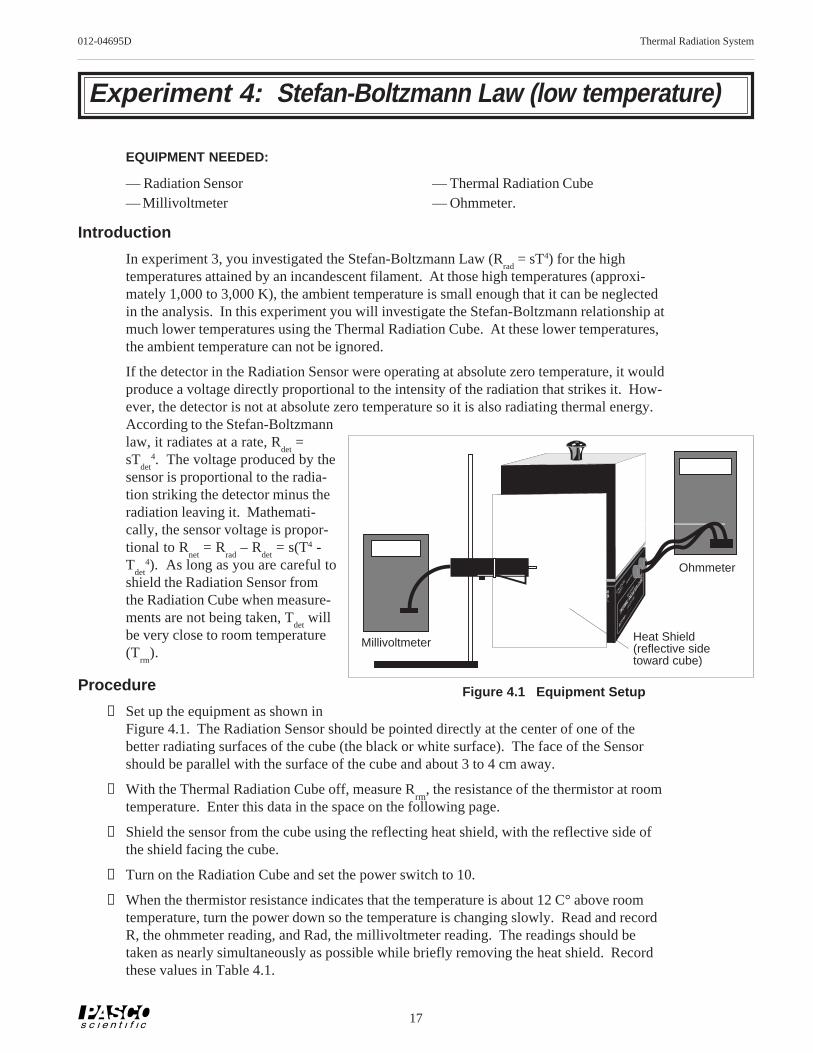
Experiment 4: Stefan-Boltzmann Law (low temperature)
In experiment 3, you investigated the Stefan-Boltzmann Law (Rrad
= sT4) for the hightemperatures attained by an incandescent filament. At those high temperatures (approxi-mately 1,000 to 3,000 K), the ambient temperature is small enough that it can be neglectedin the analysis. In this experiment you will investigate the Stefan-Boltzmann relationship atmuch lower temperatures using the Thermal Radiation Cube. At these lower temperatures,the ambient temperature can not be ignored.
If the detector in the Radiation Sensor were operating at absolute zero temperature, it wouldproduce a voltage directly proportional to the intensity of the radiation that strikes it. How-ever, the detector is not at absolute zero temperature so it is also radiating thermal energy.According to the Stefan-Boltzmannlaw, it radiates at a rate, R
det =
sTdet
4. The voltage produced by thesensor is proportional to the radia-tion striking the detector minus theradiation leaving it. Mathemati-cally, the sensor voltage is propor-tional to R
net = R
rad – R
det = s(T4 -
Tdet
4). As long as you are careful toshield the Radiation Sensor fromthe Radiation Cube when measure-ments are not being taken, T
det will
be very close to room temperature(T
rm).
Procedure
① Set up the equipment as shown inFigure 4.1. The Radiation Sensor should be pointed directly at the center of one of thebetter radiating surfaces of the cube (the black or white surface). The face of the Sensorshould be parallel with the surface of the cube and about 3 to 4 cm away.
② With the Thermal Radiation Cube off, measure Rrm
, the resistance of the thermistor at roomtemperature. Enter this data in the space on the following page.
③ Shield the sensor from the cube using the reflecting heat shield, with the reflective side ofthe shield facing the cube.
④ Turn on the Radiation Cube and set the power switch to 10.
⑤ When the thermistor resistance indicates that the temperature is about 12 C° above roomtemperature, turn the power down so the temperature is changing slowly. Read and recordR, the ohmmeter reading, and Rad, the millivoltmeter reading. The readings should betaken as nearly simultaneously as possible while briefly removing the heat shield. Recordthese values in Table 4.1.
Heat Shield(reflective sidetoward cube)
18
Thermal Radiation System 012-04695D
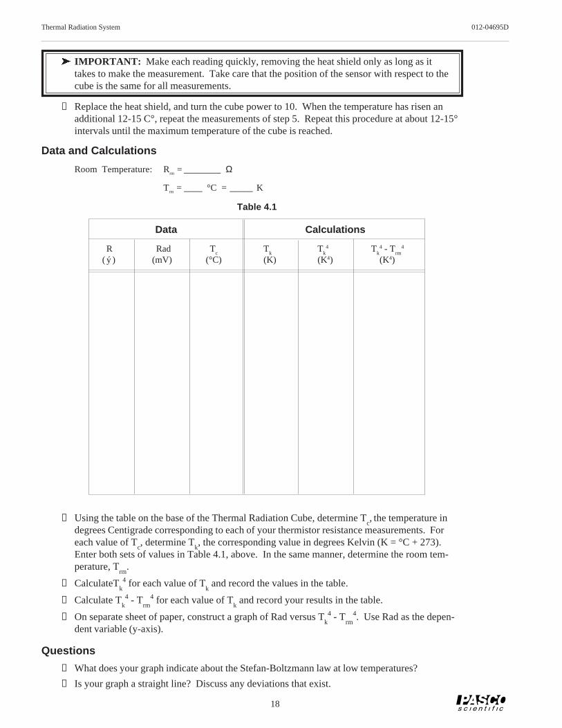
ä IMPORTANT: Make each reading quickly, removing the heat shield only as long as ittakes to make the measurement. Take care that the position of the sensor with respect to thecube is the same for all measurements.
⑥ Replace the heat shield, and turn the cube power to 10. When the temperature has risen anadditional 12-15 C°, repeat the measurements of step 5. Repeat this procedure at about 12-15°intervals until the maximum temperature of the cube is reached.
Data and Calculations
Room Temperature: Rrm = ________Ω
Trm = ____ °C = _____ K
① Using the table on the base of the Thermal Radiation Cube, determine Tc, the temperature in
degrees Centigrade corresponding to each of your thermistor resistance measurements. Foreach value of T
c, determine T
k, the corresponding value in degrees Kelvin (K = °C + 273).
Enter both sets of values in Table 4.1, above. In the same manner, determine the room tem-perature, T
rm.
② CalculateTk4 for each value of T
k and record the values in the table.
③ Calculate Tk4 - T
rm4 for each value of T
k and record your results in the table.
④ On separate sheet of paper, construct a graph of Rad versus Tk4 - T
rm4. Use Rad as the depen-
dent variable (y-axis).
Questions
① What does your graph indicate about the Stefan-Boltzmann law at low temperatures?
② Is your graph a straight line? Discuss any deviations that exist.
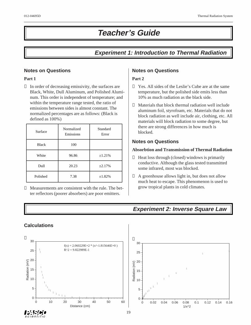
① In order of decreasing emissivity, the surfaces areBlack, White, Dull Aluminum, and Polished Alumi-num. This order is independent of temperature; andwithin the temperature range tested, the ratio ofemissions between sides is almost constant. Thenormalized percentages are as follows: (Black isdefined as 100%)
SurfaceNormalized
Emissions
Standard
Error
Black 100
White 96.86 ±1.21%
Dull 20.23 ±2.17%
Polished 7.38 ±1.82%
② Measurements are consistent with the rule. The bet-ter reflectors (poorer absorbers) are poor emitters.
Notes on Questions
Part 2
① Yes. All sides of the Leslie’s Cube are at the sametemperature, but the polished side emits less than10% as much radiation as the black side.
② Materials that block thermal radiation well includealuminum foil, styrofoam, etc. Materials that do notblock radiation as well include air, clothing, etc. Allmaterials will block radiation to some degree, butthere are strong differences in how much isblocked.
Notes on Questions
Absorbtion and Transmission of Thermal Radiation
① Heat loss through (closed) windows is primarilyconductive. Although the glass tested transmittedsome infrared, most was blocked.
② A greenhouse allows light in, but does not allowmuch heat to escape. This phenomenon is used togrow tropical plants in cold climates.
Experiment 2: Inverse Square Law
Thermal Radiation System 012-04695D
20
Notes on Questions
① The graph of Radiation versus 1/x2 is more linear,but not over the entire range. There is a distinctfalloff in intensity at the nearer distances, due to thenon-point characteristics of the lamp. (A graph ofRadiation versus 1/x2 using only data points from10cm or more is nearly linear.)
② If we use data from distances that are large com-pared to the size of the lamp filament—so that thefilament is effectively a “point”—then this data sup-ports the hypothesis.
③ The Stefan-Boltzmann Lamp is not truly a pointsource. If it were not, then there would be a falloffin light level for measurements taken close to thelamp. This falloff can be seen in our data.
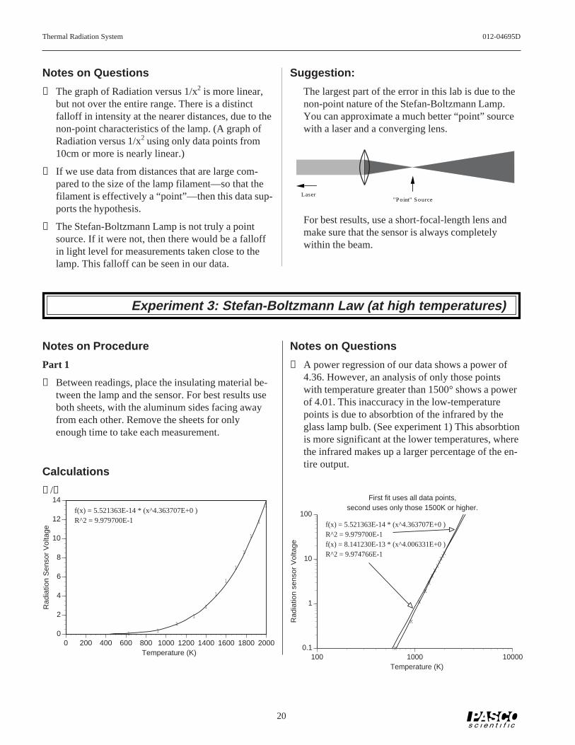
Suggestion:
The largest part of the error in this lab is due to thenon-point nature of the Stefan-Boltzmann Lamp.You can approximate a much better “point” sourcewith a laser and a converging lens.
"P oint" S ourceLaser
For best results, use a short-focal-length lens andmake sure that the sensor is always completelywithin the beam.
Notes on Questions
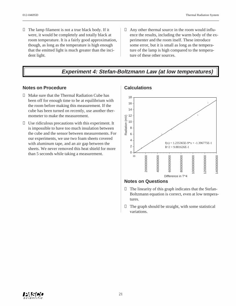
① A power regression of our data shows a power of4.36. However, an analysis of only those pointswith temperature greater than 1500° shows a powerof 4.01. This inaccuracy in the low-temperaturepoints is due to absorbtion of the infrared by theglass lamp bulb. (See experiment 1) This absorbtionis more significant at the lower temperatures, wherethe infrared makes up a larger percentage of the en-tire output.
First fit uses all data points,second uses only those 1500K or higher.
Experiment 3: Stefan-Boltzmann Law (at high temperatures)
Notes on Procedure
Part 1
③ Between readings, place the insulating material be-tween the lamp and the sensor. For best results useboth sheets, with the aluminum sides facing awayfrom each other. Remove the sheets for onlyenough time to take each measurement.
② The lamp filament is not a true black body. If itwere, it would be completely and totally black atroom temperature. It is a fairly good approximation,though, as long as the temperature is high enoughthat the emitted light is much greater than the inci-dent light.
③ Any other thermal source in the room would influ-ence the results, including the warm body of the ex-perimenter and the room itself. These introducesome error, but it is small as long as the tempera-ture of the lamp is high compared to the tempera-ture of these other sources.
Experiment 4: Stefan-Boltzmann Law (at low temperatures)
Notes on Procedure
③ Make sure that the Thermal Radiation Cube hasbeen off for enough time to be at equilibrium withthe room before making this measurement. If thecube has been turned on recently, use another ther-mometer to make the measurement.
⑤ Use ridiculous precautions with this experiment. Itis impossible to have too much insulation betweenthe cube and the sensor between measurements. Forour experiments, we use two foam sheets coveredwith aluminum tape, and an air gap between thesheets. We never removed this heat shield for morethan 5 seconds while taking a measurement.
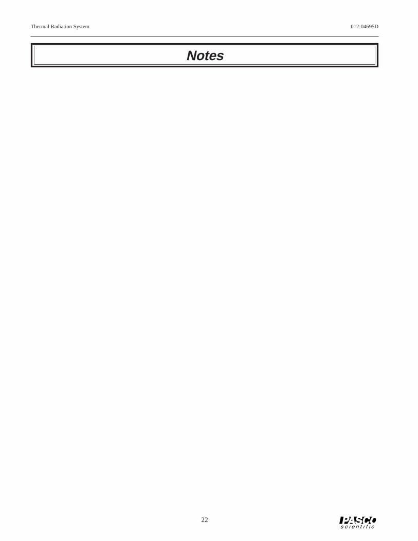
① The linearity of this graph indicates that the Stefan-Boltzmann equation is correct, even at low tempera-tures.
② The graph should be straight, with some statisticalvariations.
Thermal Radiation System 012-04695D
22
Notes
012-04695D Thermal Radiation System
23
Technical Support
Contacting Technical Support
Before you call the PASCO Technical Support staff itwould be helpful to prepare the following information:
• If your problem is computer/software related, note:
Title and Revision Date of software.
Type of Computer (Make, Model, Speed).
Type of external Cables/Peripherals.
• If your problem is with the PASCO apparatus, note:
Title and Model number (usually listed on the label).
Approximate age of apparatus.
A detailed description of the problem/sequence ofevents. (In case you can't call PASCO right away,you won't lose valuable data.)
If possible, have the apparatus within reach whencalling. This makes descriptions of individual partsmuch easier.
• If your problem relates to the instruction manual,note:
Part number and Revision (listed by month and yearon the front cover).
Have the manual at hand to discuss your questions.
Feed-Back
If you have any comments about this product or thismanual please let us know. If you have any sugges-tions on alternate experiments or find a problem in themanual please tell us. PASCO appreciates any cus-tomer feed-back. Your input helps us evaluate andimprove our product.
To Reach PASCO
For Technical Support call us at 1-800-772-8700 (toll-free within the U.S.) or (916) 786-3800.