Mechanical Properties of Wood Wood Property Definitions Anisotropic - The properties of wood are different in each of the structural directions. For example, dimensional change in response to changes in the moisture content of wood (shrinking/swelling) is much less in the longitudinal (axial) direction than it is in the transverse directions (tangential and radial), and the dimensional change in the tangential direction is typically about twice as great as in the radial direction. Orthotropic - A specific type of anisotropy, with 3 orthogonal planes of symmetry. Hygroscopic - Wood has an affinity for water, meaning that it readily picks up (adsorbs) moisture from and loses (desorbs) moisture to the atmosphere.
Transcript
Mechanical Properties of Wood
Wood Property Definitions
Anisotropic - The properties of wood are different in each of the structural directions. For example, dimensional change in response to changes in the moisture content of wood (shrinking/swelling) is much less in the longitudinal (axial) direction than it is in the transverse directions (tangential and radial), and the dimensional change in the tangential direction is typically about twice as great as in the radial direction. Orthotropic - A specific type of anisotropy, with 3 orthogonal planes of symmetry. Hygroscopic - Wood has an affinity for water, meaning that it readily picks up (adsorbs) moisture from and loses (desorbs) moisture to the atmosphere. Density - Measure of the amount of wood substance, defined as the weight per unit volume (units of lb/ft3, g/cm3, or Kg/m3). Both the weight and volume of wood vary with the moisture content of wood. Therefore, when density is measured the moisture content of the wood must be noted. Specific Gravity (SG) - The density of a material relative to the density of water. The scientific convention is to base the SG on the oven-dry mass and the volume at a saturated moisture content, also known as the green moisture content.
In some literature SG is also reported as based on an over dry mass and a volume at 0% MC or 12% MC. • Mechanical Properties - Strength and stiffness are the main mechanical property categories.They are a measure of the load (force) wood can carry before it is permanently deformed or it fails.• Strength decreases with increases in temperature. The effect is small and reversible at temperatures below 100°C. Above 100°C thermal degradation of the wood occurs and dramatic reductions in strength are possible (time dependent). o Toughness - Measure of the capacity of a material to absorb shock energy (that is, the ability to resist impact loading). Toughness is the strength property most sensitive to decay. o Compression Strength – Measure of how much load wood can support when stressed in the direction parallel to the grain. o Tension Strength – Measure of the capacity of a wood to resist a tension stress applied parallel to the grain. o Modulus of Rupture, MOR (Bending Strength) – The strength of a member loaded in bending.
• Stiffness – Measure of flexibility o Modulus of Elasticity, MOE (Bending Stiffness) – Measure of the load on a beam that will cause a deflection of 1 inch (units of psi).
Factors that influence mechanical properties include: • Moisture Content – Wood is strongest when completely dry, as the moisture content of wood increases, the strength of wood decreases. • Density – As a general rule, high density woods are stronger than low density woods. • Structural Direction – Strength varies depending on the direction relative to the grain in which the load is applied. • Time or Duration of Load - Wood gradually changes shape over time when it is loaded. This deformation is named creep and it may become permanent if the load continues for a long time. The duration of load factor used in timber design is related to the creep phenomenon. Strength decreases with duration of loading. Long term loading (10+ years) may reduce strength in bending as much as 60%.
Ⅰ. Definition of terms
The mechanical properties of wood are an expression of its behavior under applied forces. This behavior is modified in a number of ways, depending upon the kinds of force exerted on the wood and the basic differences in the organization of wood that have already been noted. Force, expressed on the basis of unit area or volume, is known as a stress. There are three kinds of primary stresses that can act on a body. The force may be acting in compression, if it shortens a dimension or reduces the volume of body; in this case there is said to be a
compressive stress, which is defined as total compression force divided by the cross-sectional area of the piece being stressed. If the force tends to increase the dimension, or volume, then it is a tension force, and a tensile stress is exerted on the body. Shear stresses result from forces, which tend to cause one portion of the body to move with respect to another in a direction parallel to their plane of contact. Bending stresses result from a combination of all three primary stresses; they cause flexure or bending in the body. The resistance of the body to the applied stress is known as the strength of the material. Since there are a number of different kinds of stresses, the strength of the material must be stated in terms of its compressive, tensile, shear or bending strength. .
In all real materials the stresses, which act on a body, produce a change in shape and size. The measure of distortion resulting from applied stress is known as strain; this value is expressed in terms of the deformation per unit area or volume. For example, compressive strain is the reduction in length of a member under compression divided by the length of the member before loading in compression. Each different type of stress produces a corresponding strain; so the kind of strain produced, i.e., compressive, tensile, shear, or bending, must be stated, as is the case with stresses.
The strain induced in a piece of wood is proportional to the applied stress, when the strain is small. It is also fully recoverable if the time of application of the stress is short and the strain remains small. This behavior was described by Robert Hooke in 1678 and is stated in the form of an equation as σ=Kε. The proportionality constant relating these two terms
is called the modulus of elasticity. The modulus of elasticity for compressive and tensile tresses is known as Yong’s-modulus (Y), and the modulus of bending elasticity is commonly indicated as E.
The elastic behavior of wood is illustrated by the straight-line portion of the curve for load and deformation, as shown in the following figure. The area under the straight-line portion of the curve represents the potential energy, or recoverable work, and is a measure of the resilience of the material. The steepness of the slope of the elastic line is a measure of the magnitude of the elastic modulus; i.e., the steeper the slope, the greater the modulus.
For any given piece of wood subjected to stress, the load-deformation curve proportional limit, beyond which the total deformation is no recoverable and some permanent set is
imposed on the specimen. In some kind of wood there is almost no demarcation of the end of the elastic portion of the curve, and the proportional limit can scarcely be defined. The set is attributed to plastic deformation of the wood and is represented by the area between the projection of the elastic line beyond the proportional limit and the actual curve. This plastic deformation increases with applied load above the proportional limit until the piece breaks or fails in some manner. The area under the stress-strain curve represents the amount of energy absorbed by the wood during its deformation, i.e., the work of deformation, and is an indication of the degree of toughness. Those samples, which bend a great deal and break gradually with the absorption of much energy, are tough. On the other hand, wood which breaks abruptly and completely with relatively small bending is brash or brittle.
Failure occurs when the strain limit has been reached, as shown by the upper limit of the load-deformation curve. The maximum crushing strength (Cmax) is a measure of the ability of a piece to withstand loads in compression parallel to the grain up to the point of failure. In bending, the magnitude of the load required to cause failure is expressed by the modulus of rupture (R). The shape of the curve for the bending load-deformation relationship in wood beyond the maximum load is determined by the toughness of the wood in bending; the curve will be abruptly terminated for brash wood but will decrease stepwise for tough material.
Resistance to impact bending is another strength property of woods; it is essentially a measurement of the energy absorption or work properties and toughness. Shear in wood is determined only in a direction parallel to the grain, since wood
is weak in shear in this axis. Resistance to shear across the grain is so much greater than that in other directions in wood that failure does not occur by shear perpendicular to the grain under any of the usual conditions of loading.
Ⅱ. Effect of specific gravity on strength of wood
The specific gravity of wood, because it is a measure of the relative amount of solid cell wall material, is the best index that exists for predicting the strength properties of wood. In general terms, without regard to the kind of wood, the relationship between specific gravity and strength can be expressed by the following equation:
S = K (G)n
where S is any one of the strength properties, K is a proportionality constant differing for each strength property, G is the specific gravity, and n is an exponent that defines the shape of the curve representing the relationship.
The effectiveness of wood in resisting any particular form of applied force is a function not only of the total amount of the wall material, but of the proportions of the cell wall components found in a given piece, and also of the amount of extractives in the cell lumen. A measure of the efficiency of the wood to resist stress is given by an index called the specific strength, which is the ratio of strength to specific gravity. This index is often referred to in general terms as the weight-strength ratio. For example, basswood and sugar maple, with roughly similar percentages of extractives and cellulose, have widely divergent specific gravity values, but show only 5 percent difference in specific compression
strength parallel to the grain for the 75 percent increase in specific gravity. In comparison with other structural materials the weight-strength ratio for wood is very favorable for some applications. The dispersal of the cell wall material as thin shells has an important effect on the flexural rigidity of wood. The resistance to bending in a beam is vastly increased if a given amount of material is arranged as a tubular structure rather than as a solid rod. For this reason wood has a high index of rigidity in comparison with solid structural materials and is well suited for use in situations that require elastic stability, such as for long beams and columns or stressed skin construction. On the other hand, wood suffers in comparison with metals for uses that require high shear and compression resistance, because the very distribution of wood substance that increases the rigidity in bending reduces the shear and compression efficiency.
Ⅲ. Effect of moisture content on strength of wood
Most of the strength properties and elastic characteristics of wood vary inversely with the moisture content of the wood below the fiber saturation point. This behavior is understandable when one considers the dispersal, or concentration, of the solid wood substance which occurs when the wood gains or loses moisture. In effect, the changes in moisture affect specific gravity values, as has been pointed out earlier, and result in changes in strength. The variations in strength of wood, due to the changes in moisture content, are
expressed as percentages of change of a given strength property for each 1 percent change in moisture content, as shown in the following figure.
Above the fiber saturation point the strength properties are constant with changes in moisture content.
Ⅳ. Anisotropic behavior of wood
A material, which has different physical properties in the directions of the various structural axes, is said to be anisotropic. The cell wall exhibits definite anisotropy because of the structural organization of the materials composing it. In addition to the wall anisotropy, the nature of the thin-walled tubular cells in wood and their arrangement in respect to the axes in the stem reinforce this nonuniformity. The tubular forms of the cells and the orientation of the cellulose in the walls account for the high tensile and compressive strength of wood along the longitudinal axis and the low resistance to collapse under forces applied perpendicular to the long cell axis. As a consequence, compressive, tensile, and shear strengths vary widely between the longitudinal and the lateral directions in wood. This basically affects the ways in which wood can be employed. For example, the ratio of compression strength parallel to the grain (C‖) to the compression perpendicular to the grain (C⊥) varies from a minimum of 4 in hardwoods containing thick-walled fibers with small diameters to a maximum of 12 in thin-walled tracheids of conifers. This means that wood is 4 to 12 times stronger in compression parallel to the grain than it is perpendicular to the grain. Finally, mechanical properties of wood also vary somewhat between the radial and tangential axes in the lateral
directions principally because of the orientation of the rays in the radial direction.
Ⅴ. Nondestructive stress determination in lumber
In wood both strength and the corresponding elasticity is dependent upon specific gravity and the presence of defects such as reaction wood and slope of grain. It has been demonstrated that there are very strong correlations between modulus of rupture and elasticity in bending, maximum compressive strength parallel to the grain and Yong’s modulus in compression, and also between maximum tensile strength and modulus of elasticity in tension. The determination of elasticity in pieces of wood of structural size is quite simple and can be performed without damage of the wood using either static or vibrational methods. These facts are used as the basis for several related systems of determining stress grades in dimension lumber. The most common systems employ equipment, which bends the lumber slightly as the piece passes through a series of rollers. The load or deflection at the rolls is measured electrically; a small computer calculates the elasticity and converts it to bending strength. The effects of all the factors influencing the allowable strength and elasticity are automatically integrated and accounted for in the stress value which the machine stamps on the piece.
Ⅵ. Time-dependent properties of wood
Deformation in wood under stress is the result of two independent components operating simultaneously. An elastic deformation is the immediate response of wood to an applied load. The elastic behavior of wood results from the presence and behavior of the cellulose microfibils which exhibit elastic response to load application and removal; i.e., the deformation is fully recoverable when the load is removed.
The second component of deformation is the plastic deformation of wood with time, which occurs as the result of the flow properties of the lignin fraction of the cell walls under load. This plastic deformation begins with the first application of load and increase with time. Recovery of plastic deformation in wood is slow and eventually amounts to only about half of the total deformation.
Plastic flow affects the use of wood as structural members in two ways. (1) Under a constant magnitude of load wood deforms plastically in direct relation to the duration of the load application. This characteristic phenomenon is known as creep (2) A piece of wood maintained at a constant deformation will show a decreasing magnitude of stress resistance to the deformation with increasing time. This phenomenon of decreasing stress resistance of the wood, as the result of
plastic flow is known as relaxation. Wood under a constant deformation will exhibit a reduction of internal stress resistance to about 70 percent of the magnitude, which existed at the time of the initiation of the deformation.
Duration of loading has a marked relation to the magnitude of the load required to cause failure in a wooden member. Standard stress values for wood, such as the modulus of rupture, determined on the basis of short-term stress duration of less than 5 minutes, are more than two-thirds greater than the load to cause failure over a 10-year period. In contrast, if the load is applied very rapidly, as in impact, the magnitude of stress required to produce failure is about 25 percent higher than is indicated by standard test values, i.e., those based on load duration of less than 5 minutes. This relationship between load level and duration of load is very important for design purposes. Bending and compression stresses but not modulus of elasticity are commonly modified for duration of load when designing structures. Shear stresses are also modified for load duration. However, it has been shown that in dry wood of the same species the effect on high-strength wood is much less than in low-strength wood.
Ⅶ. Degradative changes in strength of wood
Wood in service can be subjected to a wide range of conditions, which may result in degradative chemical changes in the wood. The most important of the degradative reactions affect the cellulose and depend on a number of interrelated factors, such as:
temperature;
length of time of exposure to the temperature;
moisture content of the wood;
pH of the system in which wood is maintained.
A. Immediate temperature response of wood /
The short-term response in strength of wood to changes in temperature is degradative only for extremely low temperature at high moisture contents and for temperatures at or above the ignition point of wood. Both the strength and elastic properties of wood vary inversely with temperature at a given moisture content and directly with specific gravity. The various mechanical properties are affected to different degree. The order of decreasing influence of temperature on strength properties is: compression parallel to the grain, modulus of rupture, shear, bending elasticity, and tensile strength.
The importance of this type of temperature response becomes most evident at the extremes of the range. Thoroughly frozen wood with high moisture content is much more subject to longitudinal splits and brittle fracture than the same kind of wood at room temperatures. On the other extreme of the temperature scale, steam bending of wood employs the principle that wet wood, at elevated temperatures, has lower strength and modulus of elasticity in bending than at room temperatures, because of the greater plasticity. The heated wood can be bent to shape while still wet, and if cooled and dried under restraint will retain most of the induced bend with little loss of strength.
B. Permanent changes in wood with temperature and time
Wood at any level of moisture content, when subject to temperatures up to 150℉ for relatively short periods of time and then returned to normal room temperatures, shows no loss of strength or change in elastic properties. This also applies to wood exposed to repeated cycles of temperatures below freezing. In contrast, wood which is heated in the temperature range between 150℉ and the ignition point for any appreciable length of time, and subsequently tested at room temperatures, will show a permanent loss of strength and elastic properties. These changes in the mechanical properties of wood so treated are the result of hydrolysis of the cellulose.
The common practice of heating wood in water or in water solutions induces changes in the wood, which are related to many of the known chemical reactions of the constituents of the wood. Water, which is at or near the boiling point, promotes hydrolysis of the chemical compounds in wood. As a result of this hydrolysis, wood loses bending strength according to the acidity of the water and the length of time of heating. Curves illustrating this loss of bending strength of wood, when heated in water at 200℉,are shown in the following figure. The degradation of the hardwoods is greater than that shown for softwoods under the same conditions.
Exposure of untreated wood to normal temperatures for a sufficiently long period results in characteristic degradation of the strength properties. Studies of old timbers from ancient buildings free from the effects of decay and not heated above temperatures normally prevailing in the temperate zone indicate that strength in old timbers is directly related to the hydrolytic changes in the cellulose fraction. The marked loss in strength for the hardwood (Zeldova), shown in the following figure, results from a relatively rapid decrease in the percentage of the cellulosic fraction. The strength curves shown for the softwood (Chamaecyparis) are significantly correlated with the percentage changes in the crystalline cellulose content. This fraction increases for the first 100 to 200 years, and then steadily decreases to an ultimate level about equal to the original condition. All strength properties follow the same pattern. The hemicelluloses and lignin percentages in wood remain about the same regardless of time. Comparable changes in chemical composition and strength can be induced in wood by heating at temperatures in excess of 100℃, in sealed tubes, for periods as short as a few days.
THE MECHANICAL PROPERTIES OF WOOD
INTRODUCTION
The mechanical properties of wood are its fitness and ability to resist applied or external forces. By external force is meant any force outside of a given piece of material which tends to deform it in any manner. It is largely such properties that determine the use of wood for structural and building purposes and innumerable other uses of which furniture, vehicles, implements, and tool handles are a few common examples.
Knowledge of these properties is obtained through experimentation either in the employment of the wood in practice or by means of special testing apparatus in the laboratory. Owing to the wide range of variation in wood it is necessary that a great number of tests be made and that so far as possible all disturbing factors be eliminated. For comparison of different kinds or sizes a standard method of testing is necessary and the values must be expressed in some defined units. For these reasons laboratory experiments if properly conducted have many advantages over any other method.
One object of such investigation is to find unit values for strength and stiffness, etc. These, because of the complex structure of wood, cannot have a constant value which will be exactly repeated in each test, even though no error be made. The most that can be accomplished is to find average values, the amount of variation above and below, and the laws which govern the variation. On account of the great variability in strength of different specimens of wood even
from the same stick and appearing to be alike, it is important to eliminate as far as possible all extraneous factors liable to influence the results of the tests.
The mechanical properties of wood considered are: (1) stiffness and elasticity, (2) tensile strength, (3) compressive or crushing strength, (4) shearing strength, (5) transverse or bending strength, (6) toughness, (7) hardness, (8) cleavability, (9) resilience. In connection with these, associated properties of importance are briefly treated.
In making use of figures indicating the strength or other mechanical properties of wood for the purpose of comparing the relative merits of different species, the fact should be borne in mind that there is a considerable range in variability of each individual material
FUNDAMENTAL CONSIDERATIONS AND DEFINITIONS
Study of the mechanical properties of a material is concerned mostly with its behavior in relation to stresses and strains, and the factors affecting this behavior. A stress is a distributed force and may be defined as the mutual action (1) of one body upon another, or (2) of one part of a body upon another part. In the first case the stress is external; in the other internal. The same stress may be internal from one point of view and external from another. An external force is
always balanced by the internal stresses when the body is in equilibrium.
If no external forces act upon a body its particles assume certain relative positions, and it has what is called its natural shape and size. If sufficient external force is applied the natural shape and size will be changed. This distortion or deformation of the material is known as the strain. Every stress produces a corresponding strain, and within a certain limit (see elastic limit) the strain is directly proportional to the stress producing it.1 The same intensity of stress, however, does not produce the same strain in different materials or in different qualities of the same material. No strain would be produced in a perfectly rigid body, but such is not known to exist.
A unit stress is the stress on a unit of the sectional area.
A unit strain is the strain per unit of length.
As the stress increases there is a corresponding increase in the strain. This ratio may be graphically shown by means of a diagram or curve plotted with the increments of load or stress as ordinates and the increments of strain as abscissæ. This is known as the stress-strain diagram. Within the limit mentioned above the diagram is a straight line. If the results of similar experiments on different specimens are plotted to the same scales, the diagrams furnish a ready means for comparison. The greater the resistance a material offers to deformation the steeper or nearer the vertical axis will be the line.
Figure 1Stress-strain diagrams of two longleaf pine beams. E.L. = elastic limit. The
areas of the triangles 0(EL)A and 0(EL)B represent the elastic resilience of the dry and green beams, respectively.
There are three kinds of internal stresses, namely, (1) tensile, (2) compressive, and (3) shearing. When external forces act upon a bar in a direction away from its ends or a direct pull, the stress is a tensile stress; when toward the ends or a direct push, compressive stress. In the first instance the strain is an elongation; in the second a shortening. Whenever the forces tend to cause one portion of the material to slide upon another adjacent to it the action is called a shear. The action is that of an ordinary pair of shears. When riveted plates slide on each other the rivets are sheared off.
These three simple stresses may act together, producing compound stresses, as in flexure. When a bow is bent there is a compression of the fibres on the inner or concave side and an elongation of the fibres on the outer or convex side. There is also a tendency of the various fibres to slide past one another in a longitudinal direction. If the bow were made of two or more separate pieces of equal length it would be noted on bending that slipping occurred along the surfaces of contact, and that the ends would no longer be even. If these pieces were securely glued together they would no longer slip, but the tendency to do so would exist just the same. Moreover, it would be found in the latter case that the bow
would be much harder to bend than where the pieces were not glued together—in other words, the stiffness of the bow would be materially increased.
Stiffness is the property by means of which a body acted upon by external forces tends to retain its natural size and shape, or resists deformation. Thus a material that is difficult to bend or otherwise deform is stiff; one that is easily bent or otherwise deformed is flexible. Flexibility is not the exact counterpart of stiffness, as it also involves toughness and pliability.
If successively larger loads are applied to a body and then removed it will be found that at first the body completely regains its original form upon release from the stress—in other words, the body is elastic. No substance known is perfectly elastic, though many are practically so under small loads. Eventually a point will be reached where the recovery of the specimen is incomplete. This point is known as the elastic limit, which may be defined as the limit beyond which it is impossible to carry the distortion of a body without producing a permanent alteration in shape. After this limit has been exceeded, the size and shape of the specimen after removal of the load will not be the same as before, and the difference or amount of change is known as the permanent set.
Elastic limit as measured in tests and used in design may be defined as that unit stress at which the deformation begins
to increase in a faster ratio than the applied load. In practice the elastic limit of a material under test is determined from the stress-strain diagram. It is that point in the line where the diagram begins perceptibly to curve.2 (See Fig. 1.)
Resilience is the amount of work done upon a body in deforming it. Within the elastic limit it is also a measure of the potential energy stored in the material and represents the amount of work the material would do upon being released from a state of stress. This may be graphically represented by a diagram in which the abscissæ represent the amount of deflection and the ordinates the force acting. The area included between the stress-strain curve and the initial line (which is zero) represents the work done. (See Fig. 1.) If the unit of space is in inches and the unit of force is in pounds the result is inch-pounds. If the elastic limit is taken as the apex of the triangle the area of the triangle will represent the elastic resilience of the specimen. This amount of work can be applied repeatedly and is perhaps the best measure of the toughness of the wood as a working quality, though it is not synonymous with toughness.
Permanent set is due to the plasticity of the material. A perfectly plastic substance would have no elasticity and the smallest forces would cause a set. Lead and moist clay are nearly plastic and wood possesses this property to a greater or less extent. The plasticity of wood is increased by wetting, heating, and especially by steaming and boiling. Were it not for this property it would be impossible to dry wood without
destroying completely its cohesion, due to the irregularity of shrinkage.
A substance that can undergo little change in shape without breaking or rupturing is brittle. Chalk and glass are common examples of brittle materials. Sometimes the word brash is used to describe this condition in wood. A brittle wood breaks suddenly with a clean instead of a splintery fracture and without warning. Such woods are unfitted to resist shock or sudden application of load.
The measure of the stiffness of wood is termed the modulus of elasticity.
TENSILE STRENGTH
Tension results when a pulling force is applied to opposite ends of a body. This external pull is communicated to the interior, so that any portion of the material exerts a pull or tensile force upon the remainder, the ability to do so depending upon the property of cohesion. The result is an elongation or stretching of the material in the direction of the applied force. The action is the opposite of compression.
Wood exhibits its greatest strength in tension parallel to the grain, and it is very uncommon in practice for a specimen to be pulled in two lengthwise. This is due to the difficulty of making the end fastenings secure enough for the full tensile strength to be brought into play before the fastenings shear off longitudinally.
The tensile strength of wood parallel to the grain depends upon the strength of the fibres and is affected not only by the nature and dimensions of the wood elements but also by their arrangement. It is greatest in straight-grained specimens with thick-walled fibres. Cross grain of any kind materially reduces the tensile strength of wood, since the tensile strength at right angles to the grain is only a small fraction of that parallel to the grain.
Failure of wood in tension parallel to the grain occurs sometimes in flexure, especially with dry material. The tension portion of the fracture is nearly the same as though the piece were pulled in two lengthwise. The fibre walls are torn across obliquely and usually in a spiral direction. There is practically no pulling apart of the fibres, that is, no separation of the fibres along their walls, regardless of their thickness. The nature of tension failure is apparently not affected by the moisture condition of the specimen, at least not so much so as the other strength values.
Tension
Failure types of clear wood in tension parallel to grain: (a) splintering tension, (b) combined tension and shear, (c) shear, (d) brittle tension.
Failure types of clear wood in tension perpendicular to grain: (a) tension failure of earlywood, (b) shearing along a growth ring, (c) tension failure of wood rays.
Tension at right angles to the grain is closely related to cleavability. When wood fails in this manner the thin fibre walls are torn in two lengthwise while the thick-walled fibres are usually pulled apart along the primary wall.
COMPRESSIVE OR CRUSHING STRENGTH
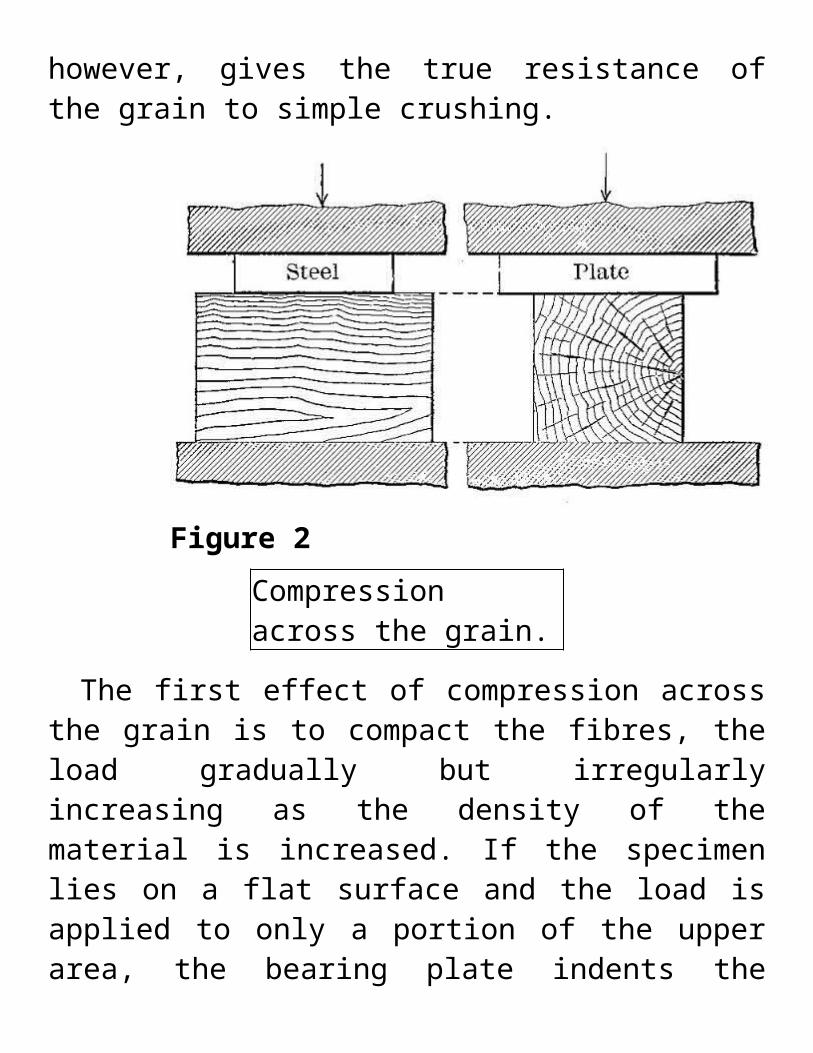
Compression across the grain is very closely related to hardness and transverse shear. There are two ways in which wood is subjected to stress of this kind, namely, (1) with the load acting over the entire area of the specimen, and (2) with a load concentrated over a portion of the area. The latter is the condition more commonly met with in practice, as, for example, where a post rests on a horizontal sill, or a rail rests
on a cross-tie. The former condition, however, gives the true resistance of the grain to simple crushing.
Figure 2Compression across the grain.
The first effect of compression across the grain is to compact the fibres, the load gradually but irregularly increasing as the density of the material is increased. If the specimen lies on a flat surface and the load is applied to only a portion of the upper area, the bearing plate indents the wood, crushing the upper fibres without affecting the lower part. (See Fig. 3.) As the load increases the projecting ends sometimes split horizontally. (See Fig. 4.) The irregularities in the load are due to the fact that the fibres collapse a few at a time, beginning with those with the thinnest walls. The
projection of the ends increases the strength of the material directly beneath the compressing weight by introducing a beam action which helps support the load. This influence is exerted for a short distance only.
Figure 3Side view of failures in compression across the grain, showing crushing of blocks under bearing plate. Specimen at right shows splitting at ends.
Figure 4End view of failures in compression across the
grain, showing splitting of the ends of the test specimens.
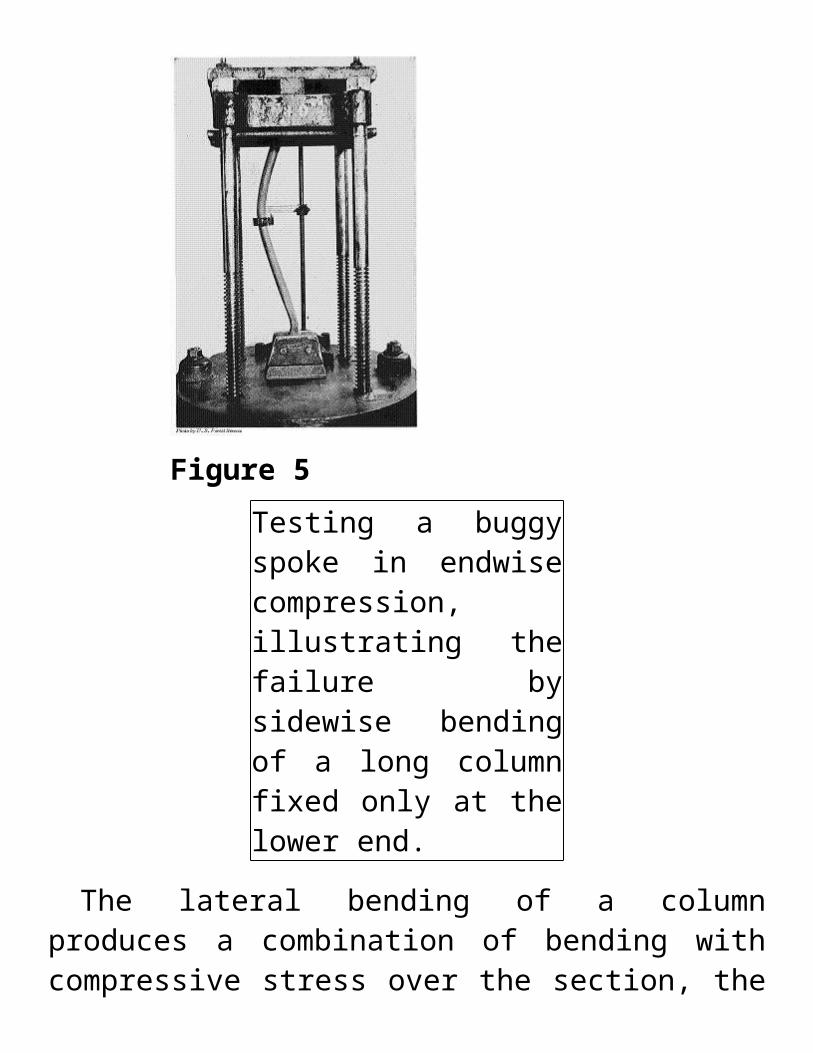
When wood is used for columns, props, posts, and spokes, the weight of the load tends to shorten the material endwise. This is endwise compression, or compression parallel to the grain. In the case of long columns, that is, pieces in which the length is very great compared with their diameter, the failure is by sidewise bending or flexure, instead of by crushing or splitting. (See Fig. 5.) A familiar instance of this action is afforded by a flexible walking-stick. If downward pressure is exerted with the hand on the upper end of the stick placed vertically on the floor, it will be noted that a definite amount of force must be applied in each instance before decided flexure takes place. After this point is reached a very slight increase of pressure very largely increases the deflection, thus obtaining so great a leverage about the middle section as to cause rupture.
Figure 5Testing a buggy spoke in endwise compression, illustrating the failure by sidewise bending of a long column fixed only at the lower end.
The lateral bending of a column produces a combination of bending with compressive stress over the section, the compressive stress being maximum at the section of greatest deflection on the concave side. The convex surface is under tension, as in an ordinary beam test. (See Fig. 6.) If the same stick is braced in such a way that flexure is prevented, its supporting strength is increased enormously, since the compressive stress acts uniformly over the section, and
failure is by crushing or splitting, as in small blocks. In all columns free to bend in any direction the deflection will be seen in the direction in which the column is least stiff. This sidewise bending can be overcome by making pillars and columns thicker in the middle than at the ends, and by bracing studding, props, and compression members of trusses. The strength of a column also depends to a considerable extent upon whether the ends are free to turn or are fixed.
Figure 6Unequal distribution of stress in a long column due to lateral bending.
The complexity of the computations depends upon the way in which the stress is applied and the manner in
which the stick bends.
.
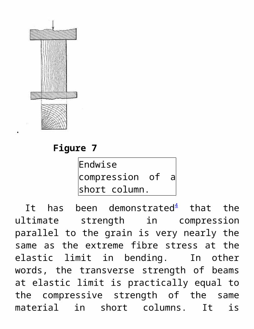
Figure 7Endwise compression of a short column.
It has been demonstrated4 that the ultimate strength in compression parallel to the grain is very nearly the same as the extreme fibre stress at the elastic limit in bending. In other words, the transverse strength of beams at elastic limit is practically equal to the compressive strength of the same material in short columns. It is accordingly possible to calculate the approximate breaking strength of beams from the compressive strength of short columns except when the wood is brittle. Since tests on endwise compression are simpler, easier to make, and less expensive than transverse bending tests, the importance of this relation is obvious,
though it does not do away with the necessity of making beam tests.
When a short column is compressed until it breaks, the manner of failure depends partly upon the anatomical structure and partly upon the degree of humidity of the wood. The fibres (tracheids in conifers) act as hollow tubes bound closely together, and in giving way they either (1) buckle, or (2) bend.5
The first is typical of any dry thin-walled cells, as is usually the case in seasoned white pine and spruce, and in the early wood of hard pines, hemlock, and other species with decided contrast between the two portions of the growth ring. As a rule buckling of a tracheid begins at the bordered pits which form places of least resistance in the walls. In hardwoods such as oak, chestnut, ash, etc., buckling occurs only in the thinnest-walled elements, such as the vessels, and not in the true fibres.
According to Jaccard , the folding of the cells is accompanied by characteristic alterations of their walls which seem to split them into extremely thin layers. When greatly magnified, these layers appear in longitudinal sections as delicate threads without any definite arrangements, while on cross section they appear as numerous concentric strata. This may be explained on the ground that the growth of a fibre is by successive layers which, under the influence of compression, are sheared
apart. This is particularly the case with thick-walled cells such as are found in late wood.
The second case, where the fibres bend with more or less regular curves instead of buckling, is characteristic of any green or wet wood, and in dry woods where the fibres are thick-walled. In woods in which the fibre walls show all gradations of thickness—in other words, where the transition from the thin-walled cells of the early wood to the thick-walled cells of the late wood is gradual—the two kinds of failure, namely, buckling and bending, grade into each other. In woods with very decided contrast between early and late wood the two forms are usually distinct. Except in the case of complete failure the cavity of the deformed cells remains open, and in hardwoods this is true not only of the wood fibres but also of the tube-like vessels. In many cases longitudinal splits occur which isolate bundles of elements by greater or less intervals. The splitting occurs by a tearing of the fibres or rays and not by the separation of the rays from the adjacent elements.
Figure 8Failures of short columns of green spruce.
Figure 9Failures of short columns of dry chestnut.
Moisture in wood decreases the stiffness of the fibre walls and enlarges the region of failure. The curve which the fibre walls make in the region of failure is more gradual and also
more irregular than in dry wood, and the fibres are more likely to be separated.
In examining the lines of rupture in compression parallel to the grain it appears that there does not exist any specific type, that is, one that is characteristic of all woods. Test blocks taken from different parts of the same log may show very decided differences in the manner of failure, while blocks that are much alike in the size, number, and distribution of the elements of unequal resistance may behave very similarly. The direction of rupture is, not influenced by the distribution of the medullary rays. These are curved with the bundles of fibres to which they are attached. In any case the failure starts at the weakest points and follows the lines of least resistance. The plane of failure, as visible on radial surfaces, is horizontal, and on the tangential surface it is diagonal.
Failure types of nonbuckling clear wood in compression parallel to grain: (a) crushing, (b) wedge splitting, (c) shearing, (d) splitting, (e) crushing and splitting, (f) brooming or end rolling.
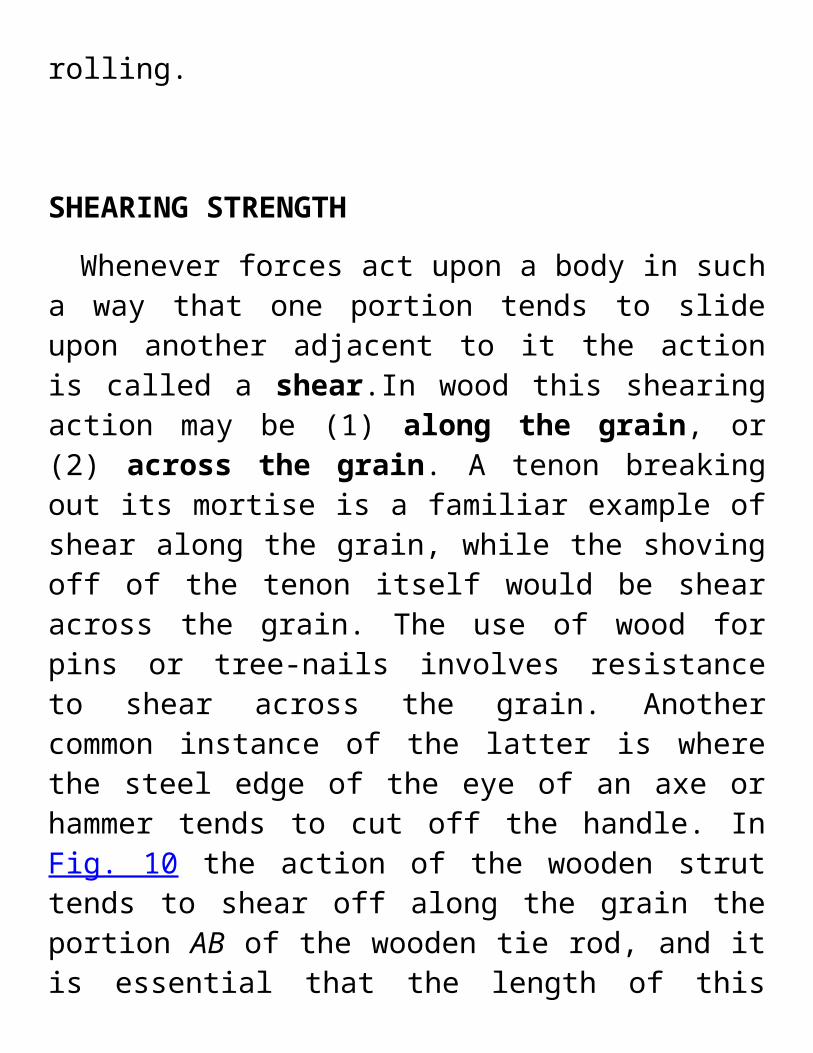
SHEARING STRENGTH
Whenever forces act upon a body in such a way that one portion tends to slide upon another adjacent to it the action is called a shear.In wood this shearing action may be (1) along the grain, or (2) across the grain. A tenon breaking out its mortise is a familiar example of shear along the grain, while
the shoving off of the tenon itself would be shear across the grain. The use of wood for pins or tree-nails involves resistance to shear across the grain. Another common instance of the latter is where the steel edge of the eye of an axe or hammer tends to cut off the handle. In Fig. 10 the action of the wooden strut tends to shear off along the grain the portion AB of the wooden tie rod, and it is essential that the length of this portion be great enough to guard against it. shows characteristic failures in shear along the grain.
Figure 11Failures of test specimens in shear along the grain. In the block at the left the surface of failure is radial; in the one at the right, tangential.
Both shearing stresses may act at the same time. Thus the weight carried by a beam tends to shear it off at right angles to the axis; this stress is equal to the resultant force acting perpendicularly at any point, and in a beam uniformly loaded and supported at either end is maximum at the points of support and zero at the centre. In addition there is a shearing force tending to move the fibres of the beam past each other in a longitudinal direction. (See Fig. 12.) This longitudinal shear is maximum at the neutral plane and decreases toward the upper and lower surfaces.
Shearing across the grain is so closely related to compression at right angles to the grain and to hardness that there is little to be gained by making separate tests upon it. Knowledge of shear parallel to the grain is important, since wood frequently fails in that way.
Oblique shearing stresses are developed in a bar when it is subjected to direct tension or compression. The maximum shearing stress occurs along a plane when it makes an angle of 45 degrees with the axis of the specimen. In this case,
(See Fig. 13.) The effect of oblique shear is often visible in the failures of short columns. (See Fig. 14.)
Figure 14Failure of short column by oblique shear.
TRANSVERSE OR BENDING STRENGTH: BEAMS
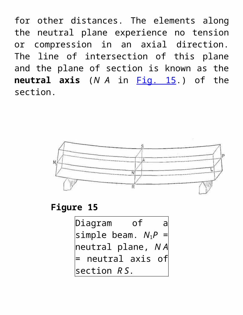
When external forces acting in the same plane are applied at right angles to the axis of a bar so as to cause it to bend, they occasion a shortening of the longitudinal fibres on the concave side and an elongation of those on the convex side. Within the elastic limit the relative stretching and contraction of the fibres is directly9] proportional to their distances from a plane intermediate between them—the neutral plane. (N1P in Fig. 15.) Thus the fibres half-way between the neutral plane and the outer surface experience only half as much shortening or elongation as the outermost or extreme fibres. Similarly for other distances. The elements along the neutral plane experience no tension or compression in an axial direction. The line of intersection of this plane and the plane of section is known as the neutral axis (N A in Fig. 15.) of the section.
Figure 15Diagram of a simple beam. N1P = neutral plane, N A = neutral axis of section R S.
If the bar is symmetrical and homogeneous the neutral plane is located half-way between the upper and lower surfaces, so long as the deflection does not exceed the elastic limit of the material. Owing to the fact that the tensile strength of wood is from two to nearly four times the compressive strength, it follows that at rupture the neutral plane is much nearer the convex than the concave side of the bar or beam, since the sum of all the compressive stresses on the concave portion must always equal the sum of the tensile stresses on the convex portion. The neutral plane begins to change from its central position as soon as the elastic limit has been passed. Its location at any time is very uncertain.
The external forces acting to bend the bar also tend to rupture it at right angles to the neutral plane by causing one transverse section to slip past another. This stress at any
point is equal to the resultant perpendicular to the axis of the forces acting at this point, and is termed the transverse shear (or in the case of beams, vertical shear).
In addition to this there is a shearing stress, tending to move the fibres past one another in an axial direction, which is called longitudinal shear (or in the case of beams, horizontal shear). This stress must be taken into consideration in the design of timber structures. It is maximum at the neutral plane and decreases to zero at the outer elements of the section. The shorter the span of a beam in proportion to its height, the greater is the liability of failure in horizontal shear before the ultimate strength of the beam is reached.
Beams
There are three common forms of beams, as follows:
(1) Simple beam—a bar resting upon two supports, one near each end. (See Fig. 16, No. 1.)
(2) Cantilever beam—a bar resting upon one support or fulcrum, or that portion of any beam projecting out of a wall or beyond a support. (See Fig. 16, No. 2.)
(3) Continuous beam—a bar resting upon more than two supports. (See Fig. 16, No. 3.)
For rectangular beams of the same material, mode of support, and loading, the deflection is affected as follows:
(1) It is inversely proportional to the width for beams of the same length and depth. If the width is tripled the deflection is one-third as great.
(2) It is inversely proportional to the cube of the depth for beams of the same length and breadth. If the depth is tripled the deflection is one twenty-seventh as great.
(3) It is directly proportional to the cube of the span for beams of the same breadth and depth. Tripling the span gives twenty-seven times the deflection.
The number of pounds which concentrated at the centre will deflect a rectangular prismatic simple beam one inch may be found from the preceding formulæ by substituting D = 1" and solving for P'. The formulæ then becomes:
Strength of Beams
The measure of the breaking strength of a beam is expressed in terms of unit stress by a modulus of rupture, which is a purely hypothetical expression for points beyond the elastic limit
It is evident that for rectangular prismatic beams of the same material, mode of support, and loading, the load which a given beam can support varies as follows:
(1) It is directly proportional to the breadth for beams of the same length and depth, as is the case with stiffness.
(2) It is directly proportional to the square of the height for beams of the same length and breadth, instead of as the cube of this dimension as in stiffness.
(3) It is inversely proportional to the span for beams of the same breadth and depth and not to the cube of this dimension as in stiffness.
The fact that the strength varies as the square of the height and the stiffness as the cube explains the relationship of bending to thickness. Were the law the same for strength and stiffness a thin piece of material such as a sheet of paper could not be bent any further without breaking than a thick piece, say an inch board.
Kinds of Loads
There are various ways in which beams are loaded, of which the following are the most important:
(1) Uniform load occurs where the load is spread evenly over the beam.
(2) Concentrated load occurs where the load is applied at single point or points.
(3) Live or immediate load is one of momentary or short duration at any one point, such as occurs in crossing a bridge.
(4) Dead or permanent load is one of constant and indeterminate duration, as books on a shelf. In the case of a bridge the weight of the structure itself is the dead load. All large beams support a uniform dead load consisting of their own weight.
The effect of dead load on a wooden beam may be two or more times that produced by an immediate load of the same weight. Loads greater than the elastic limit are unsafe and will generally result in rupture if continued long enough. A beam may be considered safe under permanent load when the deflections diminish during equal successive periods of time. A continual increase in deflection indicates an unsafe load which is almost certain to rupture the beam eventually.
Variations in the humidity of the surrounding air influence the deflection of dry wood under dead load, and increased deflections during damp weather are cumulative and not recovered by subsequent drying. In the case of longleaf pine, dry beams may with safety be loaded permanently to within three-fourths of their elastic limit as determined from ordinary static tests. Increased moisture content, due to greater humidity of the air, lowers the elastic limit of wood so that what was a safe load for the dry material may become unsafe.
When a dead load not great enough to rupture a beam has been removed, the beam tends gradually to recover its former shape, but the recovery is not always complete. If specimens from such a beam are tested in the ordinary testing machine it will be found that the application of the dead load did not affect the stiffness, ultimate strength, or elastic limit of the material. In other words, the deflections and recoveries produced by live loads are the same as would
have been produced had not the beam previously been subjected to a dead load.11
Maximum load is the greatest load a material will support and is usually greater than the load at rupture.
Safe load is the load considered safe for a material to support in actual practice. It is always less than the load at elastic limit and is usually taken as a certain proportion of the ultimate or breaking load.
Application of Loads
There are three12 general methods in which loads may be applied to beams, namely:
(1) Static loading or the gradual imposition of load so that the moving parts acquire no appreciable momentum. Loads are so applied in the ordinary testing machine.
(2) Sudden imposition of load without initial velocity. "Thus in the case of placing a load on a beam, if the load be brought into contact with the beam, but its weight sustained by external means, as by a cord, and then this external support be suddenly (instantaneously) removed, as by quickly cutting the cord, then, although the load is already
touching the beam (and hence there is no real impact), yet the beam is at first offering no resistance, as it has yet suffered no deformation. Furthermore, as the beam deflects the resistance increases, but does not come to be equal to the load until it has attained its normal deflection. In the meantime there has been an unbalanced force of gravity acting, of a constantly diminishing amount, equal at first to the entire load, at the normal deflection. But at this instant the load and the beam are in motion, the hitherto unbalanced force having produced an accelerated velocity, and this velocity of the weight and beam gives to them an energy, or vis viva, which must now spend itself in overcoming an excess of resistance over and above the imposed load, and the whole mass will not stop until the deflection (as well as the resistance) has come to be equal to twice that corresponding to the static load imposed. Hence we say the effect of a suddenly imposed load is to produce twice the deflection and stress of the same load statically applied. It must be evident, however, that this case has nothing in common with either the ordinary 'static' tests of structural materials in testing-machines, or with impact tests."13
(3) Impact, shock, or blow.14 There are various common uses of wood where the material is subjected to sudden shocks and jars or impact. Such is the action on the felloes and spokes of a wagon wheel passing over a rough road; on a hammer handle when a blow is struck; on a maul when it strikes a wedge.
Resistance to impact is resistance to energy which is measured by the product of the force into the space through which it moves, or by the product of one-half the moving mass which causes the shock into the square of its velocity. The work done upon the piece at the instant the velocity is entirely removed from the striking body is equal to the total energy of that body. It is impossible, however, to get all of the energy of the striking body stored in the specimen, though the greater the mass and the shorter the space through which it moves, or, in other words, the greater the proportion of weight and the smaller the proportion of velocity making up the energy of the striking body, the more energy the specimen will absorb. The rest is lost in friction, vibrations, heat, and motion of the anvil.
In impact the stresses produced become very complex and difficult to measure, especially if the velocity is high, or the mass of the beam itself is large compared to that of the weight.
The difficulties attending the measurement of the stresses beyond the elastic limit are so great that commonly they are not reckoned. Within the elastic limit the formulæ for calculating the stresses are based on the assumption that the deflection is proportional to the stress in this case as in static tests.
A common method of making tests upon the resistance of wood to shock is to support a small beam at the ends and
drop a heavy weight upon it in the middle. (See Fig. 40.) The height of the weight is increased after each drop and records of the deflection taken until failure. The total work done upon the specimen is equal to the area of the stress-strain diagram plus the effect of local inertia of the molecules at point of contact.
The stresses involved in impact are complicated by the fact that there are various ways in which the energy of the striking body may be spent:
(a) It produces a local deformation of both bodies at the surface of contact, within or beyond the elastic limit. In testing wood the compression of the substance of the steel striking-weight may be neglected, since the steel is very hard in comparison with the wood. In addition to the compression of the fibres at the surface of contact resistance is also offered by the inertia of the particles there, the combined effect of which is a stress at the surface of contact often entirely out of proportion to the compression which would result from the action of a static force of the same magnitude. It frequently exceeds the crushing strength at the extreme surface of contact, as in the case of the swaging action of a hammer on the head of an iron spike, or of a locomotive wheel on the steel rail. This is also the case when a bullet is shot through a board or a pane of glass without breaking it as a whole.
(b) It may move the struck body as a whole with an accelerated velocity, the resistance consisting of the inertia of the body. This effect is seen when a croquet ball is struck with a mallet.
(c) It may deform a fixed body against its external supports and resistances. In making impact tests in the laboratory the test specimen is in reality in the nature of a cushion between two impacting bodies, namely, the striking weight and the base of the machine. It is important that the mass of this base be sufficiently great that its relative velocity to that of the common centre of gravity of itself and the striking weight may be disregarded.
(d) It may deform the struck body as a whole against the resisting stresses developed by its own inertia, as, for example, when a baseball bat is broken by striking the ball.
Impact testing is difficult to conduct satisfactorily and the data obtained are of chief value in a relative sense, that is, for comparing the shock-resisting ability of woods of which like specimens have been subjected to exactly identical treatment. Yet this test is one of the most important made on wood, as it brings out properties not evident from other tests. Defects and brittleness are revealed by impact better than by any other kind of test. In common practice nearly all external stresses are of the nature of impact. In fact, no two moving bodies can come together without impact stress. Impact is
therefore the commonest form of applied stress, although the most difficult to measure.
Failures in Timber Beams
If a beam is loaded too heavily it will break or fail in some characteristic manner. These failures may be classified according to the way in which they develop, as tension, compression, and horizontal shear; and according to the appearance of the broken surface, as brash, and fibrous. A number of forms may develop if the beam is completely ruptured.
Since the tensile strength of wood is on the average about three times as great as the compressive strength, a beam should, therefore, be expected to fail by the formation in the first place of a fold on the compression side due to the crushing action, followed by failure on the tension side. This is usually the case in green or moist wood. In dry material the first visible failure is not infrequently on the lower or tension side, and various attempts have been made to explain why such is the case.15
Within the elastic limit the elongations and shortenings are equal, and the neutral plane lies in the middle of the beam. (See page 23.) Later the top layer of fibres on the upper or compression side fail, and on the load increasing, the next layer of fibres fail, and so on, even though this failure may not be visible. As a result the shortenings on the upper side of the beam become considerably greater than the
elongations on the lower side. The neutral plane must be presumed to sink gradually toward the tension side, and when the stresses on the outer fibres at the bottom have become sufficiently great, the fibres are pulled in two, the tension area being much smaller than the compression area. The rupture is often irregular, as in direct tension tests. Failure may occur partially in single bundles of fibres some time before the final failure takes place. One reason why the failure of a dry beam is different from one that is moist, is that drying increases the stiffness of the fibres so that they offer more resistance to crushing, while it has much less effect upon the tensile strength.
There is considerable variation in tension failures depending upon the toughness or the brittleness of the wood, the arrangement of the grain, defects, etc., making further classification desirable. The four most common forms are:
(1) Simple tension, in which there is a direct pulling in two of the wood on the under side of the beam due to a tensile stress parallel to the grain, (See Fig. 17, No. 1.) This is common in straight-grained beams, particularly when the wood is seasoned.
(2) Cross-grained tension, in which the fracture is caused by a tensile force acting oblique to the grain. (See Fig. 17, No. 2.) This is a common form of failure where the beam has diagonal, spiral or other form of cross grain on its lower side. Since the tensile strength of wood across the
grain is only a small fraction of that with the grain it is easy to see why a cross-grained timber would fail in this manner.
(3) Splintering tension, in which the failure consists of a considerable number of slight tension failures, producing a ragged or splintery break on the under surface of the beam. (See Fig. 17, No. 3.) This is common in tough woods. In this case the surface of fracture is fibrous.
(4) Brittle tension, in which the beam fails by a clean break extending entirely through it. (See Fig. 17, No. 4.) It is characteristic of a brittle wood which gives way suddenly without warning, like a piece of chalk. In this case the surface of fracture is described as brash.
Compression failure (see Fig. 17, No. 5) has few variations except that it appears at various distances from the neutral plane of the beam. It is very common in green timbers. The compressive stress parallel to the fibres causes them to buckle or bend as in an endwise compressive test. This action usually begins on the top side shortly after the elastic limit is reached and extends downward, sometimes almost reaching the neutral plane before complete failure occurs. Frequently two or more failures develop at about the same time.
Horizontal shear failure, in which the upper and lower portions of the beam slide along each other for a portion of their length either at one or at both ends (see Fig. 17, No. 6), is fairly common in air-dry material and in green material when the ratio of the height of the beam to the span is relatively large. It is not common in small clear specimens. It is often due to shake or season checks, common in large timbers, which reduce the actual area resisting the shearing action considerably below the calculated area used in the formulæ for horizontal shear. For this reason it is unsafe, in designing large timber beams, to use shearing stresses higher than those calculated for beams that failed in horizontal
shear. The effect of a failure in horizontal shear is to divide the beam into two or more beams the combined strength of which is much less than that of the original beam. Fig. 18 shows a large beam in which two failures in horizontal shear occurred at the same end. That the parts behave independently is shown by the compression failure below the original location of the neutral plane.
Figure 18Failure of a large beam by horizontal shear. Photo by U. S, Forest Service.
TOUGHNESS: TORSION
Toughness is a term applied to more than one property of wood. Thus wood that is difficult to split is said to be tough.
Again, a tough wood is one that will not rupture until it has deformed considerably under loads at or near its maximum strength, or one which still hangs together after it has been ruptured and may be bent back and forth without breaking apart. Toughness includes flexibility and is the reverse of brittleness, in that tough woods break gradually and give warning of failure. Tough woods offer great resistance to impact and will permit rougher treatment in manipulations attending manufacture and use. Toughness is dependent upon the strength, cohesion, quality, length, and arrangement of fibre, and the pliability of the wood. Coniferous woods as a rule are not as tough as hardwoods, of which hickory and elm are the best examples.
Figure 19Torsion of a shaft.
The torsion or twisting test is useful in determining the toughness of wood. If the ends of a shaft are turned in opposite directions, or one end is turned and the other is fixed, all of the fibres except those at the axis tend to assume
the form of helices. (See Fig. 19.) The strain produced by torsion or twisting is essentially shear transverse and parallel to the fibres, combined with longitudinal tension and transverse compression. Within the elastic limit the strains increase directly as the distance from the axis of the specimen. The outer elements are subjected to tensile stresses, and as they become twisted tend to compress those near the axis. The elongated elements also contract laterally. Cross sections which were originally plane become warped. With increasing strain the lateral adhesion of the outer fibres is destroyed, allowing them to slide past each other, and reducing greatly their power of resistance. In this way the strains on the fibres nearer the axis are progressively increased until finally all of the elements are sheared apart. It is only in the toughest materials that the full effect of this action can be observed. (See Fig. 20.) Brittle woods snap off suddenly with only a small amount of torsion, and their fracture is irregular and oblique to the axis of the piece instead of frayed out and more nearly perpendicular to the axis as is the case with tough woods.
Figure 20Effect of torsion on different grades of hickory. Photo by U. S. Forest Service.
HARDNESS
The term hardness is used in two senses, namely: (1) resistance to indentation, and (2) resistance to abrasion or scratching. In the latter sense hardness combined with toughness is a measure of the wearing ability of wood and is an important consideration in the use of wood for floors, paving blocks, bearings, and rollers. While resistance to indentation is dependent mostly upon the density of the wood, the wearing qualities may be governed by other
factors such as toughness, and the size, cohesion, and arrangement of the fibres. In use for floors, some woods tend to compact and wear smooth, while others become splintery and rough. This feature is affected to some extent by the manner in which the wood is sawed; thus edge-grain pine flooring is much better than flat-sawn for uniformity of wear.
Tests for either form of hardness are of comparative value only. Tests for indentation are commonly made by penetrations of the material with a steel punch or ball. Tests for abrasion are made by wearing down wood with sandpaper or by means of a sand blast.
CLEAVABILITY
Cleavability is the term used to denote the facility with which wood is split. A splitting stress is one in which the forces act normally like a wedge. (See Fig. 21.) The plane of cleavage is parallel to the grain, either radially or tangentially.
Figure 21Cleavage of highly elastic wood. The cleft runs far ahead of the wedge.
This property of wood is very important in certain uses such as firewood, fence rails, billets, and squares. Resistance to splitting or low cleavability is desirable where wood must hold nails or screws, as in box-making. Wood usually splits more readily along the radius than parallel to the growth rings though exceptions occur, as in the case of cross grain.
Splitting involves transverse tension, but only a portion of the fibres are under stress at a time. A wood of little stiffness and strong cohesion across the grain is difficult to split, while one with great stiffness, such as longleaf pine, is easily
split. The form of the grain and the presence of knots greatly affect this quality.