77
CHABOT-LAS POSITAS COMMUNITY COLLEGE DISTRICT 5020 FRANKLIN DRIVE, PLEASANTON, CA 94588 925-485-5215 DOOR HARDWARE SPECIFICATION GUIDELINE SECTION 087100 January 2009
CHABOT-LAS POSITAS COMMUNITY COLLEGE DISTRICT
5020 FRANKLIN DRIVE, PLEASANTON, CA 94588 925-485-5215
DOOR HARDWARE SPECIFICATION GUIDELINE
SECTION 087100
January 2009
CHABOT-LAS POSITAS COMMUNITY COLLEGE DISTRICT 5020 FRANKLIN DRIVE, PLEASANTON, CA 94588
925-485-5215
DOOR HARDWARE SPECIFICATION GUIDELINE
SECTION 087100 Edit Date: January 2009
The purpose of this booklet is to support the District’s building standards for door hardware. The District maintains the following hardware and is currently stocking replacement parts. The products listed in this booklet are pursuant to Public Contract Code Section 3400. The following particular products are designated by brand name in order to match other products in use on a particular improvement, either completed or in the course of completion. No substitutions will be accepted for these products. It is the intent of this booklet to provide guidelines for the architect's specification section 087100, for product groups and the hardware schedule. It remains the architect's responsibility to coordinate these products to meet the applicable building codes, life safety codes, and ADA requirements. Section 087100 door hardware preamble must specify the following: Door and frame prep Before hardware installation, verify that all doors and frames are properly prepared to receive the specified hardware. Hollow metal frames shall be prepared for ANSI strike plates per A115.1-2 (4-7/8” high), hinge preps will be mortised and reinforced with a minimum of 8 gauge reinforcement material for closer installation. Hollow metal doors shall be properly prepared and reinforced with a minimum or 16 gauge material for either mortised or cylindrical locks as specified. It is preferred that all hollow metal doors receiving door closers have 12 gauge reinforcement. If this is not possible, the use of sex bolts is mandatory. Wood doors shall be factory prepared to receive the scheduled hardware.
Hardware installation The manufacturer’s representative for the locking devices and closing devices must inspect and approve, in writing, the installation of their products. Hardware installed incorrectly must be reported to the architect prior to the architect’s final punch list.
CHABOT-LAS POSITAS COMMUNITY COLLEGE DISTRICT SPECIFICATION GUIDELINE Manufacturers and Products
Substitutions or Alternates not permitted unless noted below. Edit Date: January 2009
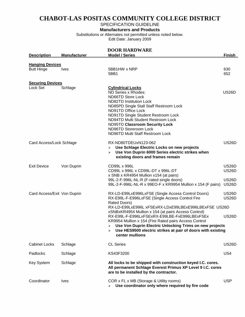
DOOR HARDWARE Description Manufacturer Model / Series Finish Hanging Devices Butt Hinge Ives 5BB1HW x NRP 630 5BB1 652 Securing Devices Lock Set Schlage Cylindrical Locks ND Series x Rhodes: US26D ND66TD Store Lock ND82TD Institution Lock ND85PD Single Stall Staff Restroom Lock ND91TD Office Lock ND91TD Single Student Restroom Lock ND94TD Multi Student Restroom Lock ND95TD Classroom Security Lock ND96TD Storeroom Lock ND96TD Multi Staff Restroom Lock Card Access/Lock Schlage RX-ND80TDEUxN123-062 US26D
Use Schlage Electric Locks on new projects Use Von Duprin 6000 Series electric strikes when
existing doors and frames remain
Exit Device Von Duprin CD99L x 996L US26D CD99L x 996L x CD99L-DT x 996L-DT US26D x SNB x KR4954 Mullion x154 (at pairs) 99L-2-F-996L-NL-R (F-rated single doors) US26D 99L-2-F-996L-NL-R x 99EO-F x KR9954 Mullion x 154 (F pairs) US26D Card Access/Exit Von Duprin RX-LD-E99LxE996LxFSE (Single Access Control Doors) US26D RX-E99L-F-E996LxFSE (Single Access Control Fire US26D Rated Doors) RX-LD-E99LxE996L xFSExRX-LDxE99LBExE996LBExFSE US26D xSNBxKR4954 Mullion x 154 (at pairs Access Control) RX-E99L-F-E996LxFSExRX-E99LBE-FxE996LBExFSEx US26D KR9954 Mullion x 154 (Fire Rated pairs Access Control
Use Von Duprin Electric Unlocking Trims on new projects Use HES9500 electric strikes at pair of doors with existing
center mullions
Cabinet Locks Schlage CL Series US26D Padlocks Schlage KS43F3200 US4 Key System Schlage All locks to be shipped with construction keyed I.C. cores. All permanent Schlage Everest Primus XP Level 9 I.C. cores are to be installed by the contractor.
Coordinator Ives COR x FL x MB (Storage & Utility rooms) USP
Use coordinator only where required by fire code
CHABOT-LAS POSITAS COMMUNITY COLLEGE DISTRICT SPECIFICATION GUIDELINE Manufacturers and Products
Substitutions or Alternates not permitted unless noted below. Edit Date: January 2009
DOOR HARDWARE Description Manufacturer Model / Series Finish
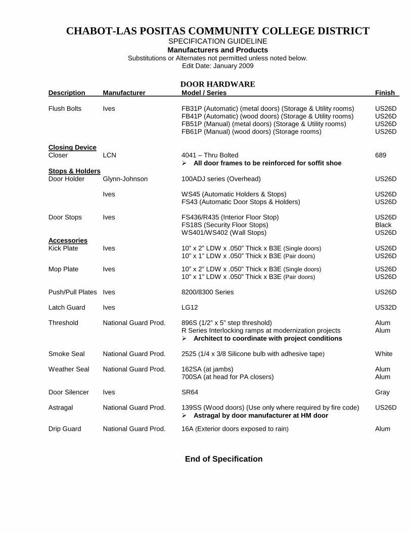
Flush Bolts Ives FB31P (Automatic) (metal doors) (Storage & Utility rooms) US26D FB41P (Automatic) (wood doors) (Storage & Utility rooms) US26D FB51P (Manual) (metal doors) (Storage & Utility rooms) US26D
FB61P (Manual) (wood doors) (Storage rooms) US26D
Closing Device Closer LCN 4041 – Thru Bolted 689
All door frames to be reinforced for soffit shoe Stops & Holders Door Holder Glynn-Johnson 100ADJ series (Overhead) US26D Ives WS45 (Automatic Holders & Stops) US26D FS43 (Automatic Door Stops & Holders) US26D Door Stops Ives FS436/R435 (Interior Floor Stop) US26D FS18S (Security Floor Stops) Black
WS401/WS402 (Wall Stops) US26D Accessories Kick Plate Ives 10” x 2” LDW x .050” Thick x B3E (Single doors) US26D 10” x 1” LDW x .050” Thick x B3E (Pair doors) US26D Mop Plate Ives 10” x 2” LDW x .050” Thick x B3E (Single doors) US26D 10” x 1” LDW x .050” Thick x B3E (Pair doors) US26D Push/Pull Plates Ives 8200/8300 Series US26D Latch Guard Ives LG12 US32D
Threshold National Guard Prod. 896S (1/2” x 5” step threshold) Alum R Series Interlocking ramps at modernization projects Alum
Architect to coordinate with project conditions Smoke Seal National Guard Prod. 2525 (1/4 x 3/8 Silicone bulb with adhesive tape) White
Weather Seal National Guard Prod. 162SA (at jambs) Alum 700SA (at head for PA closers) Alum
Door Silencer Ives SR64 Gray Astragal National Guard Prod. 139SS (Wood doors) (Use only where required by fire code) US26D
Astragal by door manufacturer at HM door Drip Guard National Guard Prod. 16A (Exterior doors exposed to rain) Alum
End of Specification
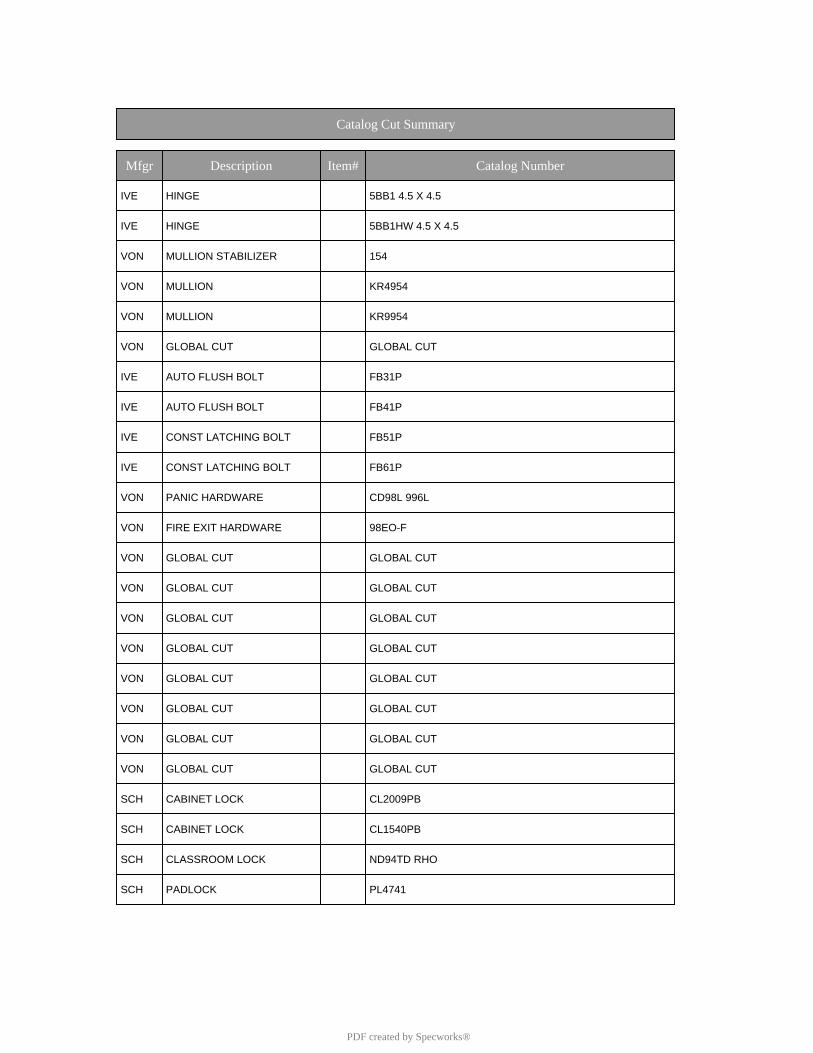
Catalog Cut Summary
Mfgr Description Item# Catalog Number
IVE HINGE 5BB1 4.5 X 4.5
IVE HINGE 5BB1HW 4.5 X 4.5
VON MULLION STABILIZER 154
VON MULLION KR4954
VON MULLION KR9954
VON GLOBAL CUT GLOBAL CUT
IVE AUTO FLUSH BOLT FB31P
IVE AUTO FLUSH BOLT FB41P
IVE CONST LATCHING BOLT FB51P
IVE CONST LATCHING BOLT FB61P
VON PANIC HARDWARE CD98L 996L
VON FIRE EXIT HARDWARE 98EO-F
VON GLOBAL CUT GLOBAL CUT
VON GLOBAL CUT GLOBAL CUT
VON GLOBAL CUT GLOBAL CUT
VON GLOBAL CUT GLOBAL CUT
VON GLOBAL CUT GLOBAL CUT
VON GLOBAL CUT GLOBAL CUT
VON GLOBAL CUT GLOBAL CUT
VON GLOBAL CUT GLOBAL CUT
SCH CABINET LOCK CL2009PB
SCH CABINET LOCK CL1540PB
SCH CLASSROOM LOCK ND94TD RHO
SCH PADLOCK PL4741
PDF created by Specworks®
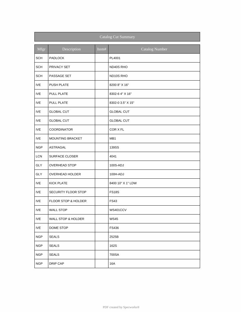
Catalog Cut Summary
Mfgr Description Item# Catalog Number
SCH PADLOCK PL4001
SCH PRIVACY SET ND40S RHO
SCH PASSAGE SET ND10S RHO
IVE PUSH PLATE 8200 8" X 16"
IVE PULL PLATE 8302-6 4" X 16"
IVE PULL PLATE 8302-0 3.5" X 15"
IVE GLOBAL CUT GLOBAL CUT
IVE GLOBAL CUT GLOBAL CUT
IVE COORDINATOR COR X FL
IVE MOUNTING BRACKET MB1
NGP ASTRAGAL 139SS
LCN SURFACE CLOSER 4041
GLY OVERHEAD STOP 100S-ADJ
GLY OVERHEAD HOLDER 100H-ADJ
IVE KICK PLATE 8400 10" X 1" LDW
IVE SECURITY FLOOR STOP FS18S
IVE FLOOR STOP & HOLDER FS43
IVE WALL STOP WS401CCV
IVE WALL STOP & HOLDER WS45
IVE DOME STOP FS436
NGP SEALS 2525B
NGP SEALS 162S
NGP SEALS 700SA
NGP DRIP CAP 16A
PDF created by Specworks®
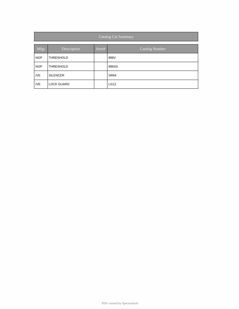
Catalog Cut Summary
Mfgr Description Item# Catalog Number
NGP THRESHOLD 896V
NGP THRESHOLD 896SS
IVE SILENCER SR64
IVE LOCK GUARD LG12
PDF created by Specworks®
J6
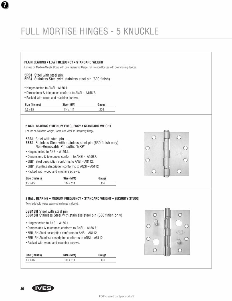
FULL MORTISE HINGES - 5 KNUCKLE
5BB1 Steel with steel pin5BB1 Stainless Steel with stainless steel pin (630 finish only)
Non-Removable Pin suffix “NRP”• Hinges tested to ANSI - A156.1. • Dimensions & tolerances conform to ANSI - A156.7.• 5BB1 Steel description conforms to ANSI - A8112.• 5BB1 Stainless description conforms to ANSI – A5112.• Packed with wood and machine screws.
Size (Inches) Size (MM) Gauge
4.5 x 4.5 114 x 114 .134
Size (Inches) Size (MM) Gauge
4.5 x 4.5 114 x 114 .134
2 BALL BEARING • MEDIUM FREQUENCY • STANDARD WEIGHT For use on Standard Weight Doors with Medium Frequency Usage
5BB1SH Steel with steel pin5BB1SH Stainless Steel with stainless steel pin (630 finish only)
• Hinges tested to ANSI - A156.1.• Dimensions & tolerances conform to ANSI - A156.7.• 5BB1SH Steel description conforms to ANSI - A8112.• 5BB1SH Stainless description conforms to ANSI – A5112.• Packed with wood and machine screws.
2 BALL BEARING • MEDIUM FREQUENCY • STANDARD WEIGHT • SECURITY STUDSTwo studs hold leaves secure when hinge is closed.
5PB1 Steel with steel pin5PB1 Stainless Steel with stainless steel pin (630 finish)
• Hinges tested to ANSI - A156.1. • Dimensions & tolerances conform to ANSI - A156.7.• Packed with wood and machine screws.
PLAIN BEARING • LOW FREQUENCY • STANDARD WEIGHT For use on Medium Weight Doors with Low Frequency Usage, not intended for use with door closing devices.
Size (Inches) Size (MM) Gauge
4.5 x 4.5 114 x 114 .134
PDF created by Specworks®
J7
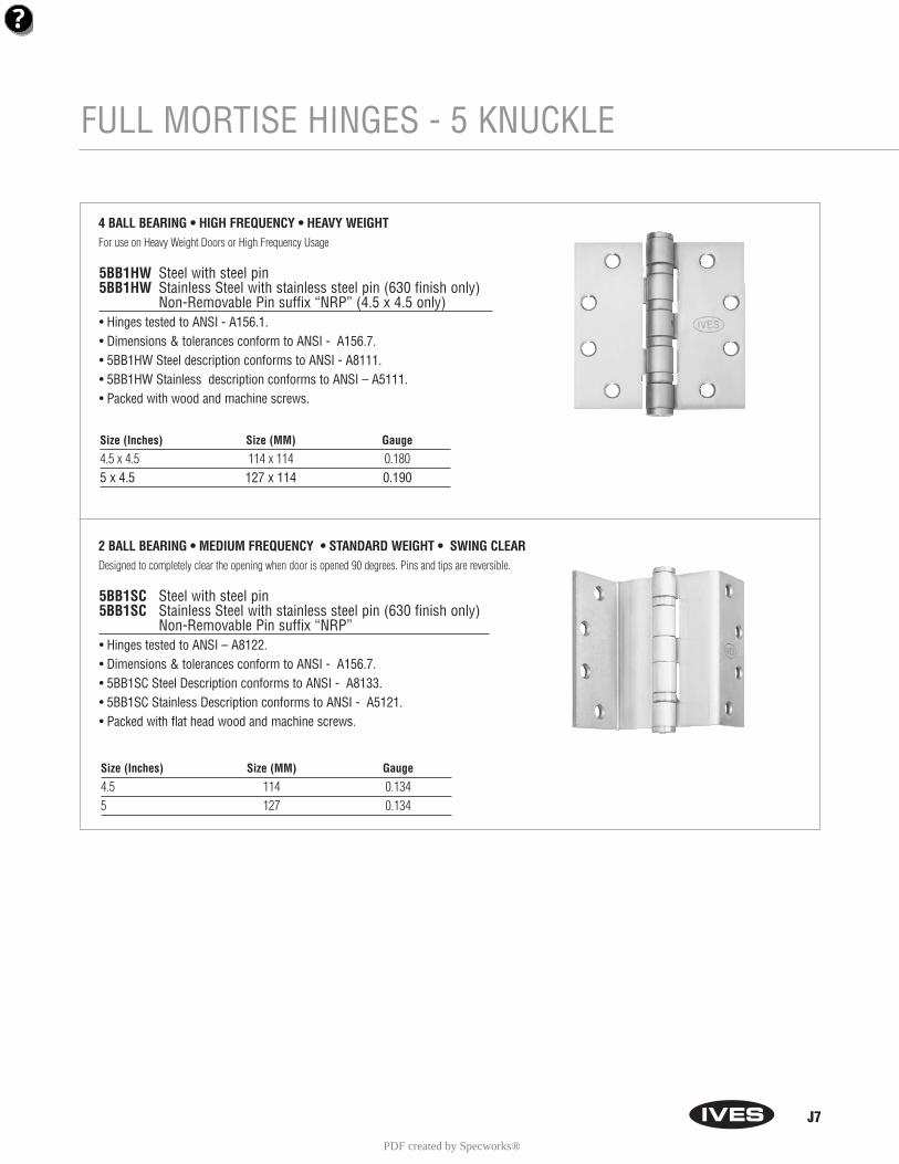
FULL MORTISE HINGES - 5 KNUCKLE
5BB1HW Steel with steel pin5BB1HW Stainless Steel with stainless steel pin (630 finish only)
Non-Removable Pin suffix “NRP” (4.5 x 4.5 only)• Hinges tested to ANSI - A156.1. • Dimensions & tolerances conform to ANSI - A156.7.• 5BB1HW Steel description conforms to ANSI - A8111.• 5BB1HW Stainless description conforms to ANSI – A5111.• Packed with wood and machine screws.
4 BALL BEARING • HIGH FREQUENCY • HEAVY WEIGHT For use on Heavy Weight Doors or High Frequency Usage
Size (Inches) Size (MM) Gauge
4.5 x 4.5 114 x 114 0.1805 x 4.5 127 x 114 0.190
5BB1SC Steel with steel pin5BB1SC Stainless Steel with stainless steel pin (630 finish only)
Non-Removable Pin suffix “NRP”• Hinges tested to ANSI – A8122. • Dimensions & tolerances conform to ANSI - A156.7.• 5BB1SC Steel Description conforms to ANSI - A8133.• 5BB1SC Stainless Description conforms to ANSI - A5121.• Packed with flat head wood and machine screws.
2 BALL BEARING • MEDIUM FREQUENCY • STANDARD WEIGHT • SWING CLEARDesigned to completely clear the opening when door is opened 90 degrees. Pins and tips are reversible.
Size (Inches) Size (MM) Gauge
4.5 114 0.1345 127 0.134
PDF created by Specworks®
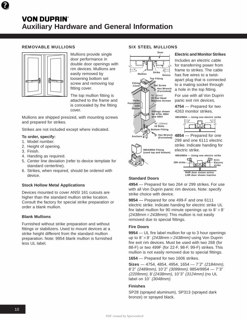
SIX STEEL MULLIONS
Electric and Monitor Strikes
Includes an electric cablefor transferring power fromframe to strikes. The cablehas five wires to a twist-apart plug that is connectedto a mating socket througha hole in the top fitting.
For use with all Von Duprinpanic exit rim devices.
4754 — Prepared for two4263 monitor strikes.
4854 — Prepared for one299 and one 6111 electricstrike. Indicate handing forelectric strike.
Standar d Door s
4954 — Prepared for two 264 or 299 strikes. For usewith all Von Duprin panic rim devices. Note: specifystrike choice with device.
9854 — Prepared for one 499-F and one 6111electric strike. Indicate handing for electric strike ULfire label mullion for 90 minute openings up to 88288(2438mm22438mm). This mullion is not easilyremoved due to special fittings.
Fire Door s
9954 — UL fire label mullion for up to 3 hour openingsup to 88288 (2438mm22438mm) using Von Duprinfire exit rim devices. Must be used with two 268 (for88-F) or two 499F (for 22-F, 98-F, 99-F) strikes. Thismullion is not easily removed due to special fittings.
1654 — Prepared for two 1606 strikes.
Sizes — 4754, 4854, 4954, 1654 — 7829 (2184mm),8829 (2489mm), 10829 (3099mm). 9854/9954 — 7839(2209mm), 88(2438mm), 10839 (3124mm) (no ULlabel on 108 (3048mm).
Finishes
SP28 (sprayed aluminum), SP313 (sprayed darkbronze) or sprayed black.
Auxiliar y Hardware and General Inf ormation T
10
REMOVABLE MULLIONS
Mullions provide singledoor performance indouble door openings withrim devices. Mullions areeasily removed byloosening bottom setscrew and removing topfitting cover.
The top mullion fitting isattached to the frame andis concealed by the fittingcover.
Mullions are shipped presized, with mounting screwsand prepared for strikes.
Strikes are not included except where indicated.
To or der, specify:1. Model number.2. Height of opening.3. Finish.4. Handing as required.5. Center line deviation (refer to device template for
standard centerline).6. Strikes, when required, should be ordered with
device.
Stoc k Hollo w Metal Applications
Devices mounted to cover ANSI 161 cutouts arehigher than the standard mullion strike location.Consult the factory for special strike preparation ororder a blank mullion.
Blank Mullions
Furnished without strike preparation and withoutfittings or stabilizers. Used to mount devices at astrike height different from the standard mullionpreparation. Note: 9954 blank mullion is furnishedless UL label.
Door
Mullion
Top Fitting
Set Scre w
1/49 (6mm)20 Flat HeadMachine Scre ws
FittingCover
StrikeFurnished
withDevice
StrikeDevice
Hex Wrenc h(Furnished)
Fittings sho wnfor 4754, 4854and 4954
3/89 (10mm)16 Bolts
Bottom Fitting
Hex Wrenc h(Furnished)Anc hor s
9854/9954 Fitting(used top and bottom)
4854/9854 — Using one electric strike
4854/9854 — Using one electric strike
RHR door sho wn activeLHR door sho wn inactive
299 strike6111Electricstrike
PDF created by Specworks®
Auxiliar y Hardware and General Inf ormation T
11
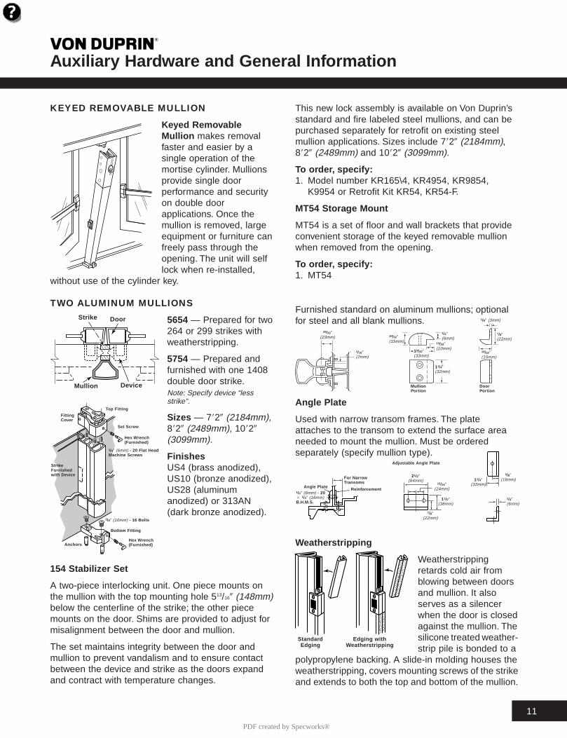
KEYED REMOVABLE MULLION
Keyed Remo vableMullion makes removalfaster and easier by asingle operation of themortise cylinder. Mullionsprovide single doorperformance and securityon double doorapplications. Once themullion is removed, largeequipment or furniture canfreely pass through theopening. The unit will selflock when re-installed,
without use of the cylinder key.
This new lock assembly is available on Von Duprin’sstandard and fire labeled steel mullions, and can bepurchased separately for retrofit on existing steelmullion applications. Sizes include 7829 (2184mm),8829 (2489mm) and 10829 (3099mm).
To or der, specify:1. Model number KR165\4, KR4954, KR9854,
K9954 or Retrofit Kit KR54, KR54-F.
MT54 Stora ge Mount
MT54 is a set of floor and wall brackets that provideconvenient storage of the keyed removable mullionwhen removed from the opening.
To or der, specify:1. MT54
TWO ALUMINUM MULLIONS
5654 — Prepared for two264 or 299 strikes withweatherstripping.
5754 — Prepared andfurnished with one 1408double door strike.Note: Specify device “lessstrike”.
Sizes — 7829 (2184mm),8829 (2489mm), 10829(3099mm).
FinishesUS4 (brass anodized),US10 (bronze anodized),US28 (aluminumanodized) or 313AN(dark bronze anodized).
154 Stabiliz er Set
A two-piece interlocking unit. One piece mounts onthe mullion with the top mounting hole 513/169 (148mm)below the centerline of the strike; the other piecemounts on the door. Shims are provided to adjust formisalignment between the door and mullion.
The set maintains integrity between the door andmullion to prevent vandalism and to ensure contactbetween the device and strike as the doors expandand contract with temperature changes.
Furnished standard on aluminum mullions; optionalfor steel and all blank mullions.
Angle Plate
Used with narrow transom frames. The plateattaches to the transom to extend the surface areaneeded to mount the mullion. Must be orderedseparately (specify mullion type).
Weather stripping
Weatherstrippingretards cold air fromblowing between doorsand mullion. It alsoserves as a silencerwhen the door is closedagainst the mullion. Thesilicone treated weather-strip pile is bonded to a
polypropylene backing. A slide-in molding houses theweatherstripping, covers mounting screws of the strikeand extends to both the top and bottom of the mullion.
����
@@@@
����
ÀÀÀÀ
����
@@@@
����
ÀÀÀÀ
����
@@@@
����
ÀÀÀÀ
����
@@@@
����
ÀÀÀÀ
����
@@@@
����
ÀÀÀÀ
����
@@@@
����
ÀÀÀÀ
����
@@@@
����
ÀÀÀÀ
����
@@@@
����
ÀÀÀÀ
����
@@@@
����
ÀÀÀÀ
����
@@@@
����
ÀÀÀÀ
����
@@@@
����
ÀÀÀÀ
����
@@@@
����
ÀÀÀÀ
����
@@@@
����
ÀÀÀÀ
����
@@@@
����
ÀÀÀÀ
����
@@@@
����
ÀÀÀÀ
����
@@@@
����
ÀÀÀÀ
����
@@@@
����
ÀÀÀÀ
����
@@@@
����
ÀÀÀÀ
����
@@@@
����
ÀÀÀÀ
����
@@@@
����
ÀÀÀÀ
����
@@@@
����
ÀÀÀÀ
����
yyyy
���������������
@@@@@@@@@@@@@@@
���������������
ÀÀÀÀÀÀÀÀÀÀÀÀÀÀÀ
���������������
@@@@@@@@@@@@@@@
���������������
ÀÀÀÀÀÀÀÀÀÀÀÀÀÀÀ
���������������
@@@@@@@@@@@@@@@
���������������
ÀÀÀÀÀÀÀÀÀÀÀÀÀÀÀ
���������������
@@@@@@@@@@@@@@@
���������������
ÀÀÀÀÀÀÀÀÀÀÀÀÀÀÀ
���������������
@@@@@@@@@@@@@@@
���������������
ÀÀÀÀÀÀÀÀÀÀÀÀÀÀÀ
���������������
@@@@@@@@@@@@@@@
���������������
ÀÀÀÀÀÀÀÀÀÀÀÀÀÀÀ
���������������
@@@@@@@@@@@@@@@
���������������
ÀÀÀÀÀÀÀÀÀÀÀÀÀÀÀ
���������������
@@@@@@@@@@@@@@@
���������������
ÀÀÀÀÀÀÀÀÀÀÀÀÀÀÀ
���������������
@@@@@@@@@@@@@@@
���������������
ÀÀÀÀÀÀÀÀÀÀÀÀÀÀÀ
���������������
@@@@@@@@@@@@@@@
���������������
ÀÀÀÀÀÀÀÀÀÀÀÀÀÀÀ
���������������
@@@@@@@@@@@@@@@
���������������
ÀÀÀÀÀÀÀÀÀÀÀÀÀÀÀ
���������������
@@@@@@@@@@@@@@@
���������������
ÀÀÀÀÀÀÀÀÀÀÀÀÀÀÀ
���������������
@@@@@@@@@@@@@@@
���������������
ÀÀÀÀÀÀÀÀÀÀÀÀÀÀÀ
���������������
@@@@@@@@@@@@@@@
���������������
ÀÀÀÀÀÀÀÀÀÀÀÀÀÀÀ
���������������
@@@@@@@@@@@@@@@
���������������
ÀÀÀÀÀÀÀÀÀÀÀÀÀÀÀ
���������������
@@@@@@@@@@@@@@@
���������������
ÀÀÀÀÀÀÀÀÀÀÀÀÀÀÀ
���������������
@@@@@@@@@@@@@@@
���������������
ÀÀÀÀÀÀÀÀÀÀÀÀÀÀÀ
���������������
@@@@@@@@@@@@@@@
���������������
ÀÀÀÀÀÀÀÀÀÀÀÀÀÀÀ
���������������
@@@@@@@@@@@@@@@
���������������
ÀÀÀÀÀÀÀÀÀÀÀÀÀÀÀ
���������������
@@@@@@@@@@@@@@@
���������������
ÀÀÀÀÀÀÀÀÀÀÀÀÀÀÀ
���������������
@@@@@@@@@@@@@@@
���������������
ÀÀÀÀÀÀÀÀÀÀÀÀÀÀÀ
���������������
yyyyyyyyyyyyyyy
1/49 (6mm) - 20 Flat HeadMachine Scre ws
Strike Door
Mullion Device
FittingCover
Top Fitting
Set Scre w
Hex Wrenc h(Furnished)
StrikeFurnishedwith De vice
3/89 (10mm) - 16 Bolts
Bottom Fitting
Hex Wrenc h(Furnished)Anc hor s
29/329(23mm)
1/169(2mm)
19/329(15mm)
1/49(6mm)
19/329(33mm)
13/329(10mm)
11/49(32mm)
MullionPor tion
DoorPor tion
19/329(15mm)
7/89(22mm)
1/89 (3mm)
1/49 (6mm) - 202 1/49 (16mm)B.H.M.S.
21/29(64mm)
15/169(24mm)
11/29(38mm)
7/89(22mm)
Angle Plate
For Narr owTransoms
Reinf orcement
Adjustab le Angle Plate
5/89(16mm)
1/49(6mm)
11/49(32mm)
Standar dEdging
Edging withWeather stripping
PDF created by Specworks®
A1
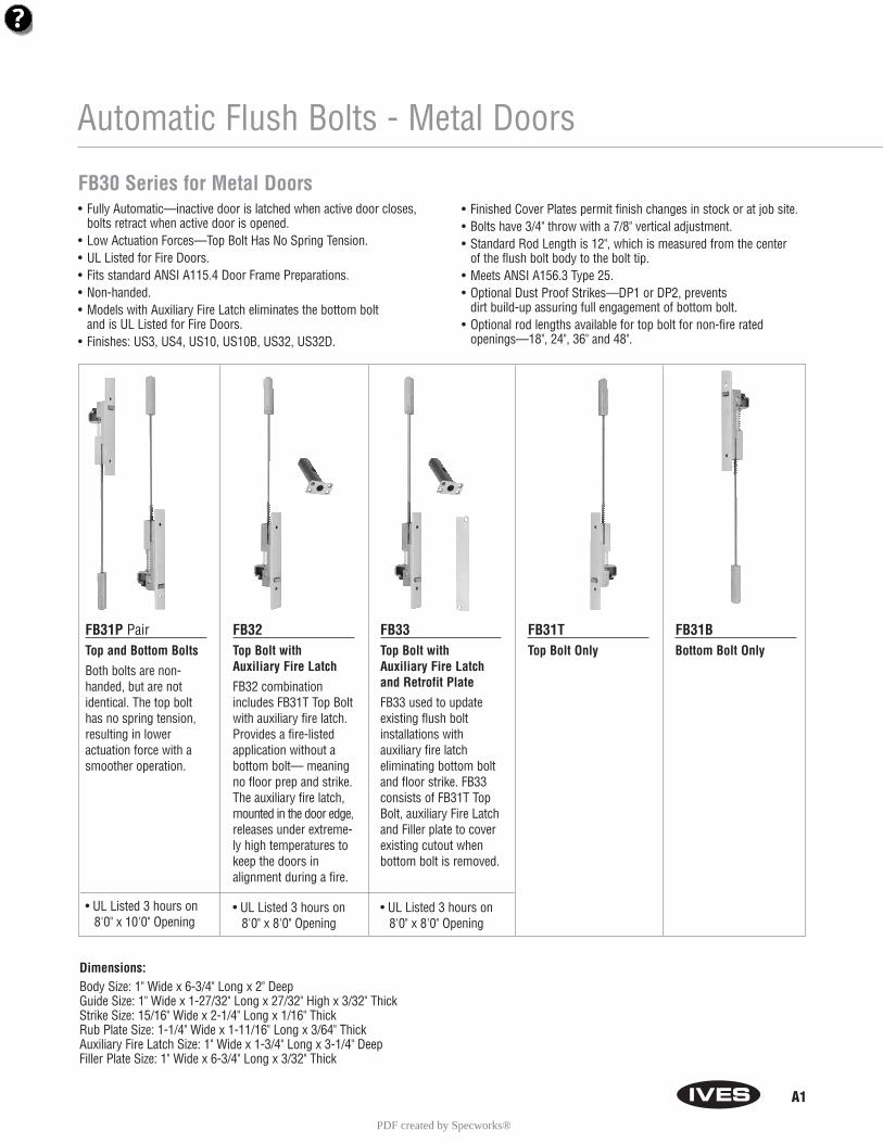
Automatic Flush Bolts - Metal Doors
FB30 Series for Metal Doors• Fully Automatic—inactive door is latched when active door closes,
bolts retract when active door is opened.• Low Actuation Forces—Top Bolt Has No Spring Tension.• UL Listed for Fire Doors.• Fits standard ANSI A115.4 Door Frame Preparations.• Non-handed.• Models with Auxiliary Fire Latch eliminates the bottom bolt
and is UL Listed for Fire Doors.• Finishes: US3, US4, US10, US10B, US32, US32D.
• Finished Cover Plates permit finish changes in stock or at job site.• Bolts have 3/4" throw with a 7/8" vertical adjustment.• Standard Rod Length is 12", which is measured from the center
of the flush bolt body to the bolt tip. • Meets ANSI A156.3 Type 25.• Optional Dust Proof Strikes—DP1 or DP2, prevents
dirt build-up assuring full engagement of bottom bolt.• Optional rod lengths available for top bolt for non-fire rated
openings—18", 24", 36" and 48".
FB31P PairTop and Bottom Bolts
Both bolts are non-handed, but are notidentical. The top bolthas no spring tension,resulting in lower actuation force with asmoother operation.
• UL Listed 3 hours on8'0" x 10'0" Opening
FB32Top Bolt with Auxiliary Fire Latch
FB32 combinationincludes FB31T Top Boltwith auxiliary fire latch.Provides a fire-listedapplication without abottom bolt— meaningno floor prep and strike.The auxiliary fire latch,mounted in the door edge,releases under extreme-ly high temperatures tokeep the doors in alignment during a fire.
• UL Listed 3 hours on8'0" x 8'0" Opening
FB33Top Bolt with Auxiliary Fire Latch and Retrofit Plate
FB33 used to updateexisting flush boltinstallations with auxiliary fire latch eliminating bottom boltand floor strike. FB33consists of FB31T TopBolt, auxiliary Fire Latchand Filler plate to coverexisting cutout whenbottom bolt is removed.
• UL Listed 3 hours on8'0" x 8'0" Opening
FB31TTop Bolt Only
FB31BBottom Bolt Only
Dimensions:Body Size: 1" Wide x 6-3/4" Long x 2" DeepGuide Size: 1" Wide x 1-27/32" Long x 27/32" High x 3/32" ThickStrike Size: 15/16" Wide x 2-1/4" Long x 1/16" ThickRub Plate Size: 1-1/4" Wide x 1-11/16" Long x 3/64" Thick Auxiliary Fire Latch Size: 1" Wide x 1-3/4" Long x 3-1/4" DeepFiller Plate Size: 1" Wide x 6-3/4" Long x 3/32" Thick
PDF created by Specworks®
A2
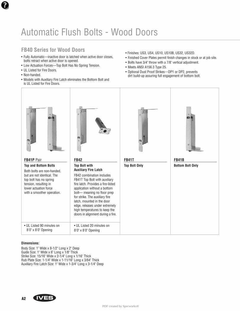
Automatic Flush Bolts - Wood Doors
FB40 Series for Wood Doors• Fully Automatic—inactive door is latched when active door closes,
bolts retract when active door is opened.• Low Actuation Forces—Top Bolt Has No Spring Tension.• UL Listed for Fire Doors.• Non-handed.• Models with Auxiliary Fire Latch eliminates the Bottom Bolt and
is UL Listed for Fire Doors.
• Finishes: US3, US4, US10, US10B, US32, US32D.• Finished Cover Plates permit finish changes in stock or at job site.• Bolts have 3/4" throw with a 7/8" vertical adjustment.• Meets ANSI A156.3 Type 25.• Optional Dust Proof Strikes—DP1 or DP2, prevents
dirt build-up assuring full engagement of bottom bolt.
FB41P PairTop and Bottom Bolts
Both bolts are non-handed, but are not identical. The top bolt has no spring tension, resulting in lower actuation forcewith a smoother operation.
• UL Listed 90 minutes on 8'0" x 8'0" Opening
FB42Top Bolt with Auxiliary Fire Latch
FB42 combination includesFB41T Top Bolt with auxiliaryfire latch. Provides a fire-listed application without a bottombolt— meaning no floor prepfor strike. The auxiliary firelatch, mounted in the dooredge, releases under extremelyhigh temperatures to keep thedoors in alignment during a fire.
• UL Listed 20 minutes on 8'0" x 8'0" Opening
FB41TTop Bolt Only
FB41BBottom Bolt Only
Dimensions:Body Size: 1" Wide x 8-1/2" Long x 2" DeepGuide Size: 1" Wide x 6" Long x 1/8" ThickStrike Size: 15/16" Wide x 2-1/4" Long x 1/16" ThickRub Plate Size: 1-1/4" Wide x 1-11/16" Long x 3/64" ThickAuxiliary Fire Latch Size: 1" Wide x 1-3/4" Long x 3-1/4" Deep
PDF created by Specworks®
A3
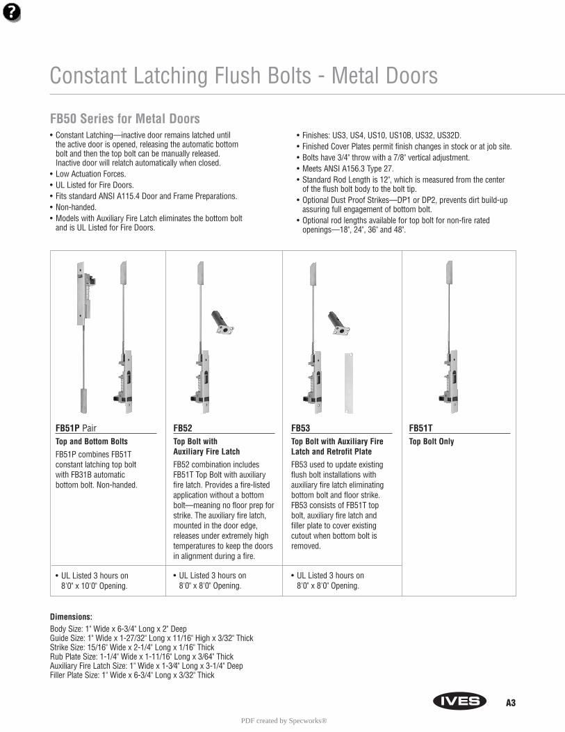
Constant Latching Flush Bolts - Metal Doors
FB50 Series for Metal Doors• Constant Latching—inactive door remains latched until
the active door is opened, releasing the automatic bottom bolt and then the top bolt can be manually released. Inactive door will relatch automatically when closed.
• Low Actuation Forces.• UL Listed for Fire Doors.• Fits standard ANSI A115.4 Door and Frame Preparations.• Non-handed.• Models with Auxiliary Fire Latch eliminates the bottom bolt
and is UL Listed for Fire Doors.
• Finishes: US3, US4, US10, US10B, US32, US32D.• Finished Cover Plates permit finish changes in stock or at job site.• Bolts have 3/4" throw with a 7/8" vertical adjustment.• Meets ANSI A156.3 Type 27.• Standard Rod Length is 12", which is measured from the center
of the flush bolt body to the bolt tip. • Optional Dust Proof Strikes—DP1 or DP2, prevents dirt build-up
assuring full engagement of bottom bolt.• Optional rod lengths available for top bolt for non-fire rated
openings—18", 24", 36" and 48".
FB51P PairTop and Bottom Bolts
FB51P combines FB51T constant latching top bolt with FB31B automatic bottom bolt. Non-handed.
• UL Listed 3 hours on 8'0" x 10'0" Opening.
FB52Top Bolt with Auxiliary Fire Latch
FB52 combination includesFB51T Top Bolt with auxiliaryfire latch. Provides a fire-listedapplication without a bottombolt—meaning no floor prep forstrike. The auxiliary fire latch,mounted in the door edge,releases under extremely hightemperatures to keep the doorsin alignment during a fire.
• UL Listed 3 hours on 8'0" x 8'0" Opening.
FB53Top Bolt with Auxiliary FireLatch and Retrofit Plate
FB53 used to update existingflush bolt installations with auxiliary fire latch eliminatingbottom bolt and floor strike.FB53 consists of FB51T topbolt, auxiliary fire latch andfiller plate to cover existingcutout when bottom bolt isremoved.
• UL Listed 3 hours on 8'0" x 8'0" Opening.
FB51TTop Bolt Only
Dimensions:Body Size: 1" Wide x 6-3/4" Long x 2" DeepGuide Size: 1" Wide x 1-27/32" Long x 11/16" High x 3/32" ThickStrike Size: 15/16" Wide x 2-1/4" Long x 1/16" ThickRub Plate Size: 1-1/4" Wide x 1-11/16" Long x 3/64" ThickAuxiliary Fire Latch Size: 1" Wide x 1-3⁄4" Long x 3-1/4" DeepFiller Plate Size: 1" Wide x 6-3/4" Long x 3/32" Thick
PDF created by Specworks®
A4
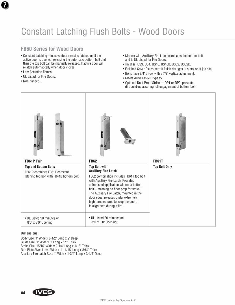
Constant Latching Flush Bolts - Wood Doors
FB60 Series for Wood Doors• Constant Latching—inactive door remains latched until the
active door is opened, releasing the automatic bottom bolt andthen the top bolt can be manually released. Inactive door willrelatch automatically when door closes.
• Low Actuation Forces.• UL Listed for Fire Doors.• Non-handed.
• Models with Auxiliary Fire Latch eliminates the bottom bolt and is UL Listed for Fire Doors.
• Finishes: US3, US4, US10, US10B, US32, US32D.• Finished Cover Plates permit finish changes in stock or at job site.• Bolts have 3/4" throw with a 7/8" vertical adjustment.• Meets ANSI A156.3 Type 27.• Optional Dust Proof Strikes—DP1 or DP2, prevents
dirt build-up assuring full engagement of bottom bolt.
FB61P PairTop and Bottom Bolts
FB61P combines FB61T constant latching top bolt with FB41B bottom bolt.
• UL Listed 90 minutes on 8'0" x 8'0" Opening
FB62Top Bolt with Auxiliary Fire Latch
FB62 combination includes FB61T top boltwith Auxiliary Fire Latch. Provides a fire-listed application without a bottombolt—meaning no floor prep for strike. The Auxiliary Fire Latch, mounted in thedoor edge, releases under extremely high temperatures to keep the doors in alignment during a fire.
• UL Listed 20 minutes on 8'0" x 8'0" Opening
FB61TTop Bolt Only
Dimensions:Body Size: 1" Wide x 8-1/2" Long x 2" DeepGuide Size: 1" Wide x 6" Long x 1/8" ThickStrike Size: 15/16" Wide x 2-1/4" Long x 1/16" ThickRub Plate Size: 1-1/4" Wide x 1-11/16" Long x 3/64" ThickAuxiliary Fire Latch Size: 1" Wide x 1-3/4" Long x 3-1/4" Deep
PDF created by Specworks®
A9
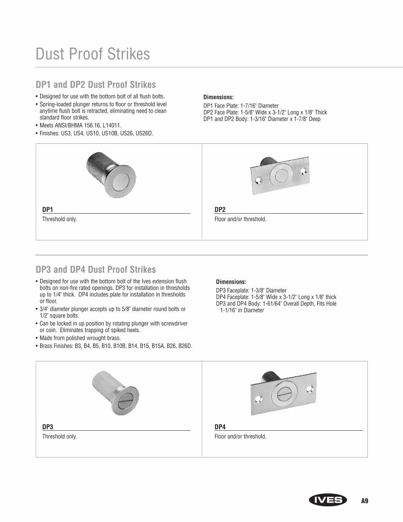
Dust Proof Strikes
DP1 and DP2 Dust Proof Strikes• Designed for use with the bottom bolt of all flush bolts. • Spring-loaded plunger returns to floor or threshold level
anytime flush bolt is retracted, eliminating need to clean standard floor strikes.
• Meets ANSI/BHMA 156.16, L14011.• Finishes: US3, US4, US10, US10B, US26, US26D.
Dimensions:DP1 Face Plate: 1-7/16" DiameterDP2 Face Plate: 1-5/8" Wide x 3-1/2" Long x 1/8" ThickDP1 and DP2 Body: 1-3/16" Diameter x 1-7/8" Deep
DP1Threshold only.
DP2Floor and/or threshold.
DP3 and DP4 Dust Proof Strikes• Designed for use with the bottom bolt of the Ives extension flush
bolts on non-fire rated openings. DP3 for installation in thresholdsup to 1/4" thick. DP4 includes plate for installation in thresholds or floor.
• 3/4" diameter plunger accepts up to 5/8" diameter round bolts or1/2" square bolts.
• Can be locked in up position by rotating plunger with screwdriver or coin. Eliminates trapping of spiked heels.
• Made from polished wrought brass.• Brass Finishes: B3, B4, B5, B10, B10B, B14, B15, B15A, B26, B26D.
Dimensions:DP3 Faceplate: 1-3/8" DiameterDP4 Faceplate: 1-5/8" Wide x 3-1/2" Long x 1/8" thickDP3 and DP4 Body: 1-61/64" Overall Depth, Fits Hole
1-1/16" in Diameter
DP3Threshold only.
DP4Floor and/or threshold.
4 © 2004 Ingersoll-Rand. May be copied for use with specification submittal.
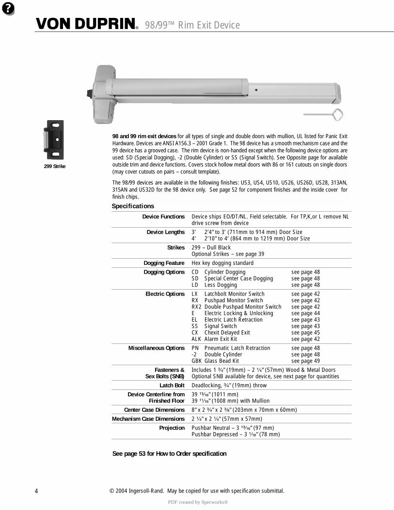
98/99™ Rim Exit Device
299 Strike
98 and 99 rim exit devices for all types of single and double doors with mullion, UL listed for Panic ExitHardware. Devices are ANSI A156.3 – 2001 Grade 1. The 98 device has a smooth mechanism case and the99 device has a grooved case. The rim device is non-handed except when the following device options areused: SD (Special Dogging), -2 (Double Cylinder) or SS (Signal Switch). See Opposite page for availableoutside trim and device functions. Covers stock hollow metal doors with 86 or 161 cutouts on single doors(may cover cutouts on pairs – consult template).
The 98/99 devices are available in the following finishes: US3, US4, US10, US26, US26D, US28, 313AN,315AN and US32D for the 98 device only. See page 52 for component finishes and the inside cover forfinish chips.
Specifications
Device Functions Device ships EO/DT/NL. Field selectable. For TP,K,or L remove NL drive screw from device
Device Lengths 3’ 2’4" to 3’ (711mm to 914 mm) Door Size4’ 2’10" to 4’ (864 mm to 1219 mm) Door Size
Strikes 299 – Dull BlackOptional Strikes – see page 39
Dogging Feature Hex key dogging standard
Dogging Options CD Cylinder Dogging see page 48 SD Special Center Case Dogging see page 48 LD Less Dogging see page 48
Electric Options LX Latchbolt Monitor Switch see page 42 RX Pushpad Monitor Switch see page 42 RX2 Double Pushpad Monitor Switch see page 42E Electric Locking & Unlocking see page 44EL Electric Latch Retraction see page 43 SS Signal Switch see page 43 CX Chexit Delayed Exit see page 45ALK Alarm Exit Kit see page 42
Miscellaneous Options PN Pneumatic Latch Retraction see page 48 -2 Double Cylinder see page 48 GBK Glass Bead Kit see page 49
Fasteners & Includes 1 ³�₄" (19mm) – 2 ¹�₄" (57mm) Wood & Metal DoorsSex Bolts (SNB) Optional SNB available for device, see next page for quantities
Latch Bolt Deadlocking, ³�₄" (19mm) throw
Device Centerline from 39 ¹³�₁₆" (1011 mm)Finished Floor 39 ¹¹�₁₆" (1008 mm) with Mullion
Center Case Dimensions 8" x 2 ³�₄" x 2 ³�₈" (203mm x 70mm x 60mm)
Mechanism Case Dimensions 2 ¹�₄" x 2 ¹�₄" (57mm x 57mm)
Projection Pushbar Neutral – 3 ¹³�₁₆" (97 mm)Pushbar Depressed – 3 ¹�₁₆" (78 mm)
See page 53 for How to Order specification
PDF created by Specworks®
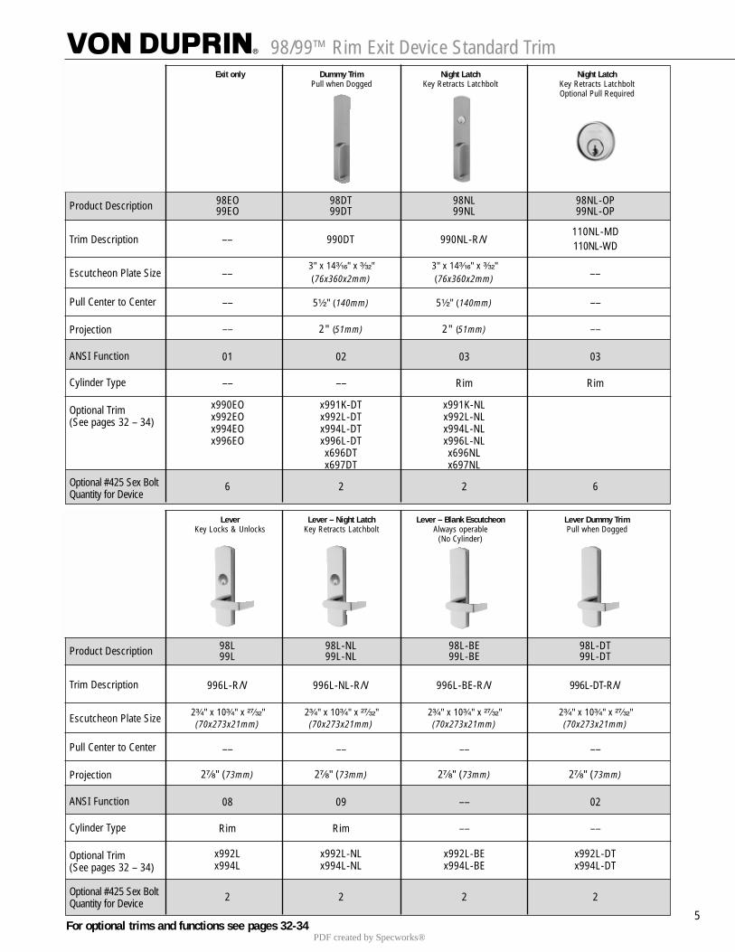
98/99™ Rim Exit Device Standard Trim
5
Exit only Dummy Trim Night Latch Night LatchPull when Dogged Key Retracts Latchbolt Key Retracts Latchbolt
Optional Pull Required
Product Description
Trim Description
Escutcheon Plate Size
Pull Center to Center
Projection
ANSI Function
Cylinder Type
Optional Trim(See pages 32 – 34)
Optional #425 Sex Bolt Quantity for Device
98EO 98DT 98NL 98NL-OP99EO 99DT 99NL 99NL-OP
110NL-MD110NL-WD
3" x 14³�₁₆" x ³�₃₂" 3" x 14³�₁₆" x ³�₃₂"(76x360x2mm) (76x360x2mm)
–– 5¹�₂" (140mm) 5¹�₂" (140mm) ––
–– 2" (51mm) 2" (51mm) ––
01 02 03 03
–– –– Rim Rim
x990EO x991K-DT x991K-NLx992EO x992L-DT x992L-NLx994EO x994L-DT x994L-NLx996EO x996L-DT x996L-NL
x696DT x696NLx697DT x697NL
6 2 2 6
–– 990DT 990NL-R/V
–– ––
Lever Lever – Night Latch Lever – Blank Escutcheon Lever Dummy TrimKey Locks & Unlocks Key Retracts Latchbolt Always operable Pull when Dogged
(No Cylinder)
Product Description
Trim Description
Escutcheon Plate Size
Pull Center to Center
Projection
ANSI Function
Cylinder Type
Optional Trim(See pages 32 – 34)
Optional #425 Sex Bolt Quantity for Device
98L 98L-NL 98L-BE 98L-DT99L 99L-NL 99L-BE 99L-DT
996L-R/V 996L-NL-R/V 996L-BE-R/V 996L-DT-R/V
2³�₄" x 10³�₄" x ²⁷�₃₂" 2³�₄" x 10³�₄" x ²⁷�₃₂" 2³�₄" x 10³�₄" x ²⁷�₃₂" 2³�₄" x 10³�₄" x ²⁷�₃₂"(70x273x21mm) (70x273x21mm) (70x273x21mm) (70x273x21mm)
–– –– –– ––
2⁷�₈" (73mm) 2⁷�₈" (73mm) 2⁷�₈" (73mm) 2⁷�₈" (73mm)
08 09 –– 02
Rim Rim –– ––
x992L x992L-NL x992L-BE x992L-DTx994L x994L-NL x994L-BE x994L-DT
2 2 2 2
For optional trims and functions see pages 32-34PDF created by Specworks®
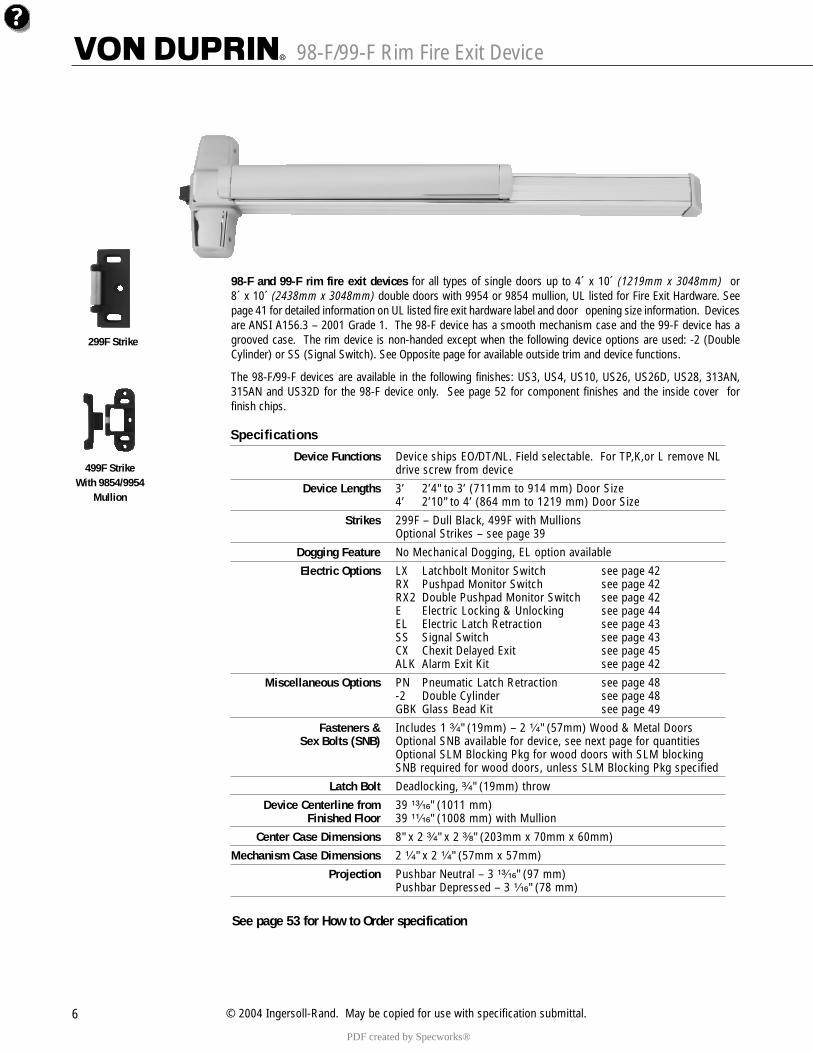
98-F/99-F Rim Fire Exit Device
6 © 2004 Ingersoll-Rand. May be copied for use with specification submittal.
98-F and 99-F rim fire exit devices for all types of single doors up to 4´ x 10´ (1219mm x 3048mm) or8´ x 10´ (2438mm x 3048mm) double doors with 9954 or 9854 mullion, UL listed for Fire Exit Hardware. Seepage 41 for detailed information on UL listed fire exit hardware label and door opening size information. Devicesare ANSI A156.3 – 2001 Grade 1. The 98-F device has a smooth mechanism case and the 99-F device has agrooved case. The rim device is non-handed except when the following device options are used: -2 (DoubleCylinder) or SS (Signal Switch). See Opposite page for available outside trim and device functions.
The 98-F/99-F devices are available in the following finishes: US3, US4, US10, US26, US26D, US28, 313AN,315AN and US32D for the 98-F device only. See page 52 for component finishes and the inside cover forfinish chips.
299F Strike
499F StrikeWith 9854/9954
Mullion
Specifications
Device Functions Device ships EO/DT/NL. Field selectable. For TP,K,or L remove NL drive screw from device
Device Lengths 3’ 2’4" to 3’ (711mm to 914 mm) Door Size4’ 2’10" to 4’ (864 mm to 1219 mm) Door Size
Strikes 299F – Dull Black, 499F with MullionsOptional Strikes – see page 39
Dogging Feature No Mechanical Dogging, EL option available
Electric Options LX Latchbolt Monitor Switch see page 42 RX Pushpad Monitor Switch see page 42 RX2 Double Pushpad Monitor Switch see page 42E Electric Locking & Unlocking see page 44EL Electric Latch Retraction see page 43 SS Signal Switch see page 43 CX Chexit Delayed Exit see page 45ALK Alarm Exit Kit see page 42
Miscellaneous Options PN Pneumatic Latch Retraction see page 48 -2 Double Cylinder see page 48 GBK Glass Bead Kit see page 49
Fasteners & Includes 1 ³�₄" (19mm) – 2 ¹�₄" (57mm) Wood & Metal DoorsSex Bolts (SNB) Optional SNB available for device, see next page for quantities
Optional SLM Blocking Pkg for wood doors with SLM blockingSNB required for wood doors, unless SLM Blocking Pkg specified
Latch Bolt Deadlocking, ³�₄" (19mm) throw
Device Centerline from 39 ¹³�₁₆" (1011 mm)Finished Floor 39 ¹¹�₁₆" (1008 mm) with Mullion
Center Case Dimensions 8" x 2 ³�₄" x 2 ³�₈" (203mm x 70mm x 60mm)
Mechanism Case Dimensions 2 ¹�₄" x 2 ¹�₄" (57mm x 57mm)
Projection Pushbar Neutral – 3 ¹³�₁₆" (97 mm)Pushbar Depressed – 3 ¹�₁₆" (78 mm)
See page 53 for How to Order specification
PDF created by Specworks®
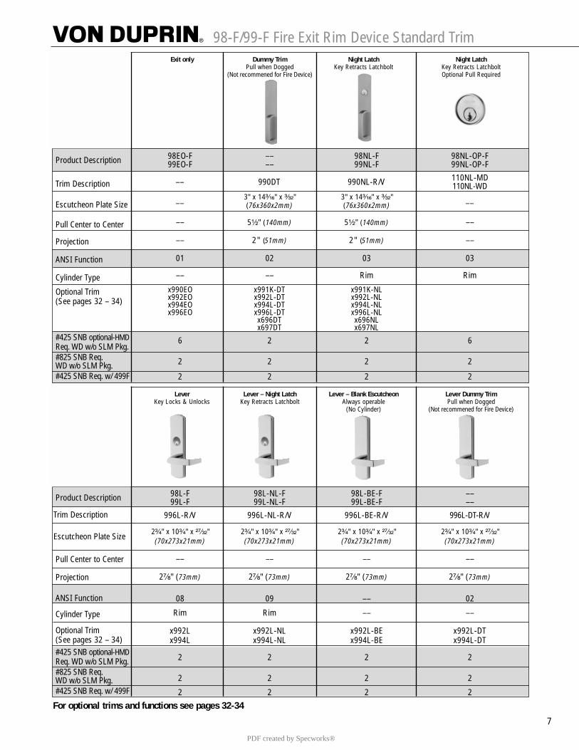
98-F/99-F Fire Exit Rim Device Standard Trim
7
Exit only Dummy Trim Night Latch Night LatchPull when Dogged Key Retracts Latchbolt Key Retracts Latchbolt
(Not recommened for Fire Device) Optional Pull Required
Product Description
Trim Description
Escutcheon Plate Size
Pull Center to Center
Projection
ANSI Function
Cylinder Type
Optional Trim(See pages 32 – 34)
#425 SNB optional-HMDReq. WD w/o SLM Pkg. #825 SNB Req. WD w/o SLM Pkg.#425 SNB Req. w/ 499F
98EO-F –– 98NL-F 98NL-OP-F99EO-F –– 99NL-F 99NL-OP-F
110NL-MD110NL-WD
3" x 14³�₁₆" x ³�₃₂" 3" x 14³�₁₆" x ³�₃₂"(76x360x2mm) (76x360x2mm)
–– 5¹�₂" (140mm) 5¹�₂" (140mm) ––
–– 2" (51mm) 2" (51mm) ––
01 02 03 03
–– –– Rim Rim
x990EO x991K-DT x991K-NLx992EO x992L-DT x992L-NLx994EO x994L-DT x994L-NLx996EO x996L-DT x996L-NL
x696DT x696NLx697DT x697NL
6 2 2 6
2 2 2 2
2 2 2 2
–– 990DT 990NL-R/V
–– ––
Lever Lever – Night Latch Lever – Blank Escutcheon Lever Dummy TrimKey Locks & Unlocks Key Retracts Latchbolt Always operable Pull when Dogged
(No Cylinder) (Not recommened for Fire Device)
Product Description
Trim Description
Escutcheon Plate Size
Pull Center to Center
Projection
ANSI Function
Cylinder Type
Optional Trim(See pages 32 – 34)#425 SNB optional-HMDReq. WD w/o SLM Pkg. #825 SNB Req. WD w/o SLM Pkg.#425 SNB Req. w/ 499F
98L-F 98L-NL-F 98L-BE-F ––99L-F 99L-NL-F 99L-BE-F ––
996L-R/V 996L-NL-R/V 996L-BE-R/V 996L-DT-R/V
2³�₄" x 10³�₄" x ²⁷�₃₂" 2³�₄" x 10³�₄" x ²⁷�₃₂" 2³�₄" x 10³�₄" x ²⁷�₃₂" 2³�₄" x 10³�₄" x ²⁷�₃₂"(70x273x21mm) (70x273x21mm) (70x273x21mm) (70x273x21mm)
–– –– –– ––
2⁷�₈" (73mm) 2⁷�₈" (73mm) 2⁷�₈" (73mm) 2⁷�₈" (73mm)
08 09 –– 02
Rim Rim –– ––
x992L x992L-NL x992L-BE x992L-DTx994L x994L-NL x994L-BE x994L-DT
2 2 2 2
2 2 2 2
2 2 2 2
For optional trims and functions see pages 32-34
PDF created by Specworks®
98/99™ Optional Trim
32 © 2004 Ingersoll-Rand. May be copied for use with specification submittal.
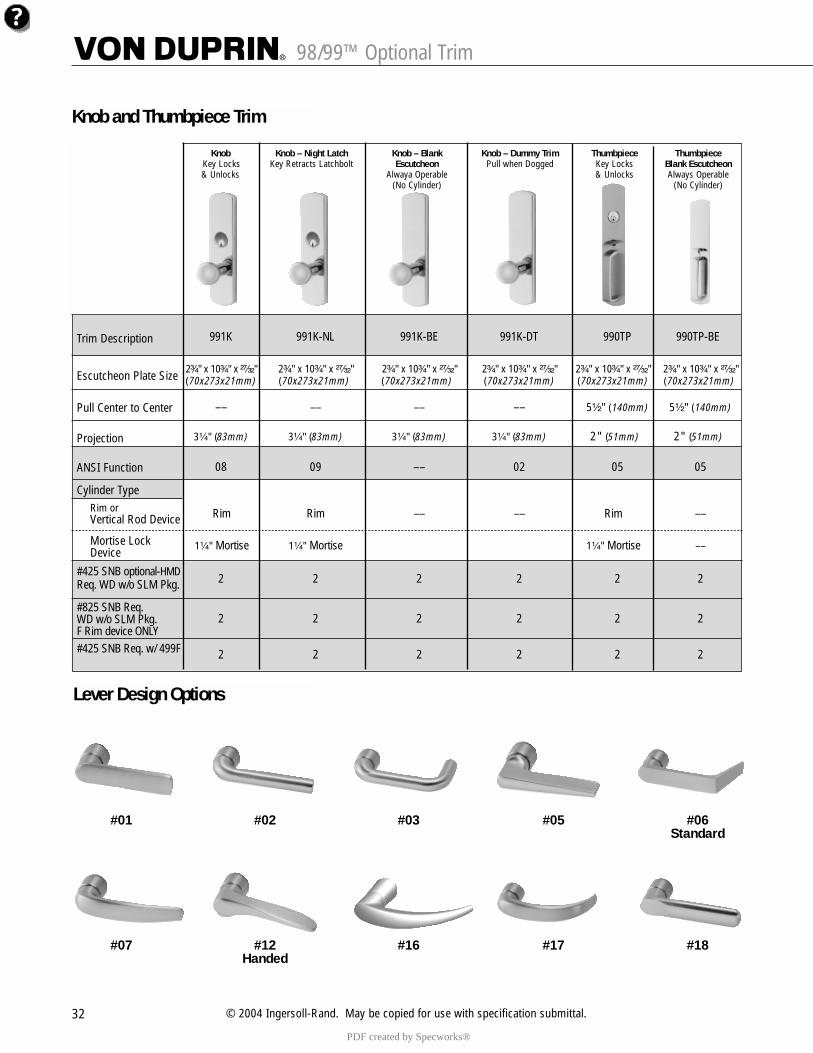
Knob Knob – Night Latch Knob – Blank Knob – Dummy Trim Thumbpiece ThumbpieceKey Locks Key Retracts Latchbolt Escutcheon Pull when Dogged Key Locks Blank Escutcheon& Unlocks Alwaya Operable & Unlocks Always Operable
(No Cylinder) (No Cylinder)
Trim Description
Escutcheon Plate Size
Pull Center to Center
Projection
ANSI Function
Cylinder TypeRim or Vertical Rod Device
Mortise Lock Device
#425 SNB optional-HMDReq. WD w/o SLM Pkg.
#825 SNB Req. WD w/o SLM Pkg.F Rim device ONLY#425 SNB Req. w/ 499F
991K 991K-NL 991K-BE 991K-DT 990TP 990TP-BE
2³�₄" x 10³�₄" x ²⁷�₃₂" 2³�₄" x 10³�₄" x ²⁷�₃₂" 2³�₄" x 10³�₄" x ²⁷�₃₂" 2³�₄" x 10³�₄" x ²⁷�₃₂" 2³�₄" x 10³�₄" x ²⁷�₃₂" 2³�₄" x 10³�₄" x ²⁷�₃₂"(70x273x21mm) (70x273x21mm) (70x273x21mm) (70x273x21mm) (70x273x21mm) (70x273x21mm)
–– –– –– –– 5¹�₂" (140mm) 5¹�₂" (140mm)
3¹�₄" (83mm) 3¹�₄" (83mm) 3¹�₄" (83mm) 3¹�₄" (83mm) 2" (51mm) 2" (51mm)
08 09 –– 02 05 05
Rim Rim –– –– Rim ––
1¹�₄" Mortise 1¹�₄" Mortise 1¹�₄" Mortise ––
2 2 2 2 2 2
2 2 2 2 2 2
2 2 2 2 2 2
Knob and Thumbpiece Trim
Lever Design Options
#01 #02 #03 #05 #06Standard
#07 #12 #16 #17 #18Handed
PDF created by Specworks®
48 © 2004 Ingersoll-Rand. May be copied for use with specification submittal.
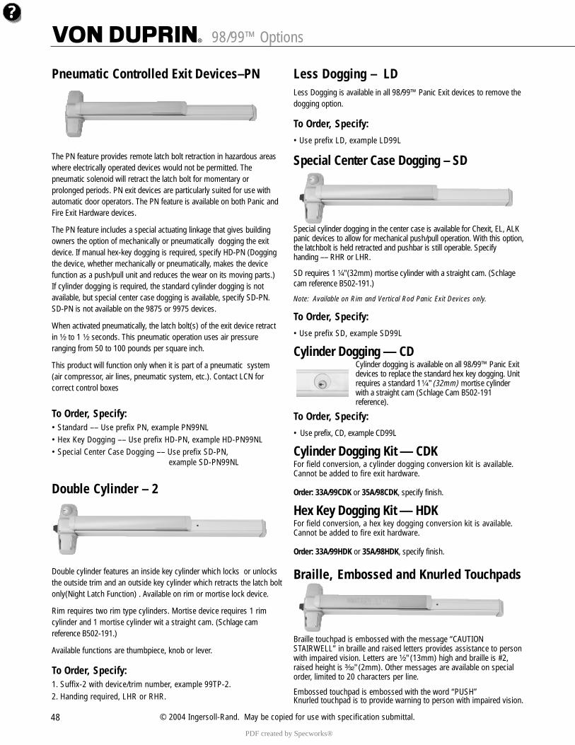
Pneumatic Controlled Exit Devices–PN
The PN feature provides remote latch bolt retraction in hazardous areaswhere electrically operated devices would not be permitted. Thepneumatic solenoid will retract the latch bolt for momentary orprolonged periods. PN exit devices are particularly suited for use withautomatic door operators. The PN feature is available on both Panic andFire Exit Hardware devices.
The PN feature includes a special actuating linkage that gives buildingowners the option of mechanically or pneumatically dogging the exitdevice. If manual hex-key dogging is required, specify HD-PN (Doggingthe device, whether mechanically or pneumatically, makes the devicefunction as a push/pull unit and reduces the wear on its moving parts.)If cylinder dogging is required, the standard cylinder dogging is notavailable, but special center case dogging is available, specify SD-PN.SD-PN is not available on the 9875 or 9975 devices.
When activated pneumatically, the latch bolt(s) of the exit device retractin ¹�₂ to 1 ¹�₂ seconds. This pneumatic operation uses air pressure ranging from 50 to 100 pounds per square inch.
This product will function only when it is part of a pneumatic system(air compressor, air lines, pneumatic system, etc.). Contact LCN for correct control boxes
To Order, Specify:• Standard –– Use prefix PN, example PN99NL• Hex Key Dogging –– Use prefix HD-PN, example HD-PN99NL• Special Center Case Dogging –– Use prefix SD-PN,
example SD-PN99NL
Double Cylinder – 2
Double cylinder features an inside key cylinder which locks or unlocksthe outside trim and an outside key cylinder which retracts the latch boltonly(Night Latch Function) . Available on rim or mortise lock device.
Rim requires two rim type cylinders. Mortise device requires 1 rimcylinder and 1 mortise cylinder wit a straight cam. (Schlage camreference B502-191.)
Available functions are thumbpiece, knob or lever.
To Order, Specify:1. Suffix-2 with device/trim number, example 99TP-2.2. Handing required, LHR or RHR.
Less Dogging – LDLess Dogging is available in all 98/99™ Panic Exit devices to remove thedogging option.
To Order, Specify:• Use prefix LD, example LD99L
Special Center Case Dogging – SD
Special cylinder dogging in the center case is available for Chexit, EL, ALKpanic devices to allow for mechanical push/pull operation. With this option,the latchbolt is held retracted and pushbar is still operable. Specifyhanding –– RHR or LHR.
SD requires 1 ¹�₄" (32mm) mortise cylinder with a straight cam. (Schlagecam reference B502-191.)
Note: Available on Rim and Vertical Rod Panic Exit Devices only.
To Order, Specify:• Use prefix SD, example SD99L
Cylinder Dogging — CDCylinder dogging is available on all 98/99™ Panic Exitdevices to replace the standard hex key dogging. Unitrequires a standard 1¹�₄" (32mm) mortise cylinderwith a straight cam (Schlage Cam B502-191reference).
To Order, Specify:• Use prefix, CD, example CD99L
Cylinder Dogging Kit — CDKFor field conversion, a cylinder dogging conversion kit is available.Cannot be added to fire exit hardware.
Order: 33A/99CDK or 35A/98CDK, specify finish.
Hex Key Dogging Kit — HDKFor field conversion, a hex key dogging conversion kit is available.Cannot be added to fire exit hardware.
Order: 33A/99HDK or 35A/98HDK, specify finish.
Braille, Embossed and Knurled Touchpads
Braille touchpad is embossed with the message “CAUTIONSTAIRWELL” in braille and raised letters provides assistance to personwith impaired vision. Letters are ¹�₂" (13mm) high and braille is #2,raised height is ³�₃₂" (2mm). Other messages are available on specialorder, limited to 20 characters per line.
Embossed touchpad is embossed with the word “PUSH”Knurled touchpad is to provide warning to person with impaired vision.
98/99™ Options
PDF created by Specworks®
4343
98/99™ ELectrical Options
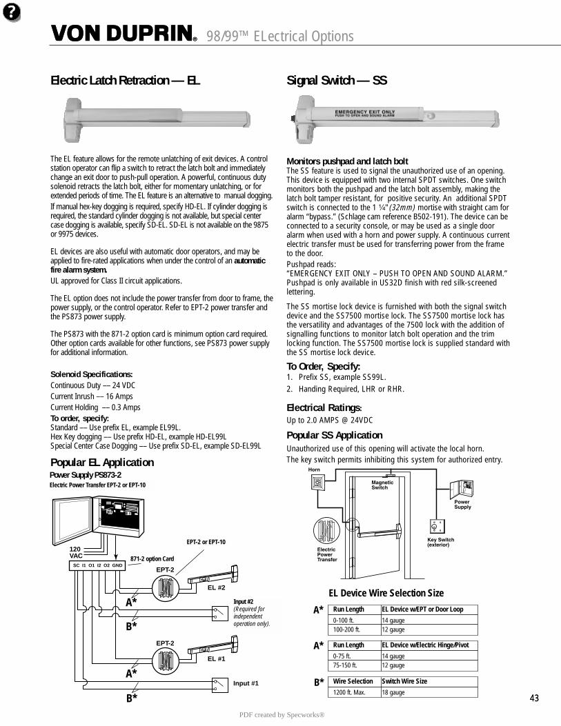
Electric Latch Retraction — EL
The EL feature allows for the remote unlatching of exit devices. A controlstation operator can flip a switch to retract the latch bolt and immediatelychange an exit door to push-pull operation. A powerful, continuous dutysolenoid retracts the latch bolt, either for momentary unlatching, or forextended periods of time. The EL feature is an alternative to manual dogging.If manual hex-key dogging is required, specify HD-EL. If cylinder dogging isrequired, the standard cylinder dogging is not available, but special centercase dogging is available, specify SD-EL. SD-EL is not available on the 9875or 9975 devices.
EL devices are also useful with automatic door operators, and may beapplied to fire-rated applications when under the control of an automaticfire alarm system.UL approved for Class II circuit applications.
The EL option does not include the power transfer from door to frame, thepower supply, or the control operator. Refer to EPT-2 power transfer andthe PS873 power supply.
The PS873 with the 871-2 option card is minimum option card required.Other option cards available for other functions, see PS873 power supplyfor additional information.
Solenoid Specifications:Continuous Duty –– 24 VDCCurrent Inrush –– 16 AmpsCurrent Holding –– 0.3 AmpsTo order, specify:Standard –– Use prefix EL, example EL99L.Hex Key dogging –– Use prefix HD-EL, example HD-EL99LSpecial Center Case Dogging –– Use prefix SD-EL, example SD-EL99L
Popular EL Application
Signal Switch — SS
Monitors pushpad and latch boltThe SS feature is used to signal the unauthorized use of an opening.This device is equipped with two internal SPDT switches. One switchmonitors both the pushpad and the latch bolt assembly, making thelatch bolt tamper resistant, for positive security. An additional SPDTswitch is connected to the 1 ¹�₄" (32mm) mortise with straight cam foralarm “bypass.” (Schlage cam reference B502-191). The device can beconnected to a security console, or may be used as a single dooralarm when used with a horn and power supply. A continuous currentelectric transfer must be used for transferring power from the frameto the door. Pushpad reads:“EMERGENCY EXIT ONLY – PUSH TO OPEN AND SOUND ALARM.”Pushpad is only available in US32D finish with red silk-screenedlettering.
The SS mortise lock device is furnished with both the signal switchdevice and the SS7500 mortise lock. The SS7500 mortise lock hasthe versatility and advantages of the 7500 lock with the addition ofsignalling functions to monitor latch bolt operation and the trimlocking function. The SS7500 mortise lock is supplied standard withthe SS mortise lock device.
To Order, Specify:1. Prefix SS, example SS99L.2. Handing Required, LHR or RHR.
Electrical Ratings:Up to 2.0 AMPS @ 24VDC
Popular SS ApplicationUnauthorized use of this opening will activate the local horn.The key switch permits inhibiting this system for authorized entry.
Power Supply PS873-2
120VAC
EL #2
EL #1
SC I1 O1 I2 O2 GNDEPT-2
EPT-2
Input #2(Required forindependentoperation only).
Input #1
A*
A*
B*
B*
Run Length EL Device w/EPT or Door Loop
0-100 ft. 14 gauge100-200 ft. 12 gauge
Run Length EL Device w/Electric Hinge/Pivot
0-75 ft. 14 gauge75-150 ft. 12 gauge
EL Device Wire Selection Size
Wire Selection Switch Wire Size
1200 ft. Max. 18 gauge
A*
A*
B*
EPT-2 or EPT-10
871-2 option Card
Input #2(Required for independent operation only).
Electric Power Transfer EPT-2 or EPT-10
PDF created by Specworks®
98/99™ Optional Lever Trim
33
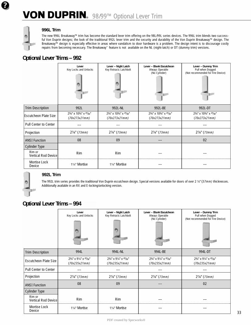
Lever Lever – Night Latch Lever – Blank Escutcheon Lever – Dummy TrimKey Locks and Unlocks Key Retracts Latchbolt Always Operable Pull when Dogged
(No Cylinder) (Not recommended for Fire Device)
Trim Description
Escutcheon Plate Size
Pull Center to Center
Projection
ANSI Function
Cylinder TypeRim or Vertical Rod Device
Mortise Lock Device
992L 992L-NL 992L-BE 992L-DT2³�₄" x 10³�₄" x ²⁷�₃₂" 2³�₄" x 10³�₄" x ²⁷�₃₂" 2³�₄" x 10³�₄" x ²⁷�₃₂" 2³�₄" x 10³�₄" x ²⁷�₃₂"(70x273x21mm) (70x273x21mm) (70x273x21mm) (70x273x21mm)
–– –– –– ––
2⁷�₈" (73mm) 2⁷�₈" (73mm) 2⁷�₈" (73mm) 2⁷�₈" (73mm)
08 09 –– 02
Rim Rim –– ––
1¹�₄" Mortise 1¹�₄" Mortise –– ––
Optional Lever Trims – 992
Optional Lever Trims – 994Lever Lever – Night Latch Lever – Blank Escutcheon Lever – Dummy Trim
Key Locks and Unlocks Key Retracts Latchbolt Always Operable Pull when Dogged(No Cylinder) (Not recommended for Fire Device)
Trim Description
Escutcheon Plate Size
Pull Center to Center
Projection
ANSI Function
Cylinder TypeRim or Vertical Rod Device
Mortise Lock Device
994L 994L-NL 994L-BE 994L-DT
2³�₄" x 9¹�₄" x ²⁷�₃₂" 2³�₄" x 9¹�₄" x ²⁷�₃₂" 2³�₄" x 9¹�₄" x ²⁷�₃₂" 2³�₄" x 9¹�₄" x ²⁷�₃₂"(70x235x21mm) (70x235x21mm) (70x235x21mm) (70x235x21mm)
–– –– –– ––
2⁷�₈" (73mm) 2⁷�₈" (73mm) 2⁷�₈" (73mm) 2⁷�₈" (73mm)
08 09 –– 02
Rim Rim –– ––
1¹�₄" Mortise 1¹�₄" Mortise –– ––
The new 996L Breakaway™ trim has become the standard lever trim offering on the 98L/99L series devices. The 996L trim blends two success-ful Von Duprin designs; the look of the traditional 992L lever trim and the security and durability of the Von Duprin Breakaway™ design. TheBreakaway™ design is especially effective in areas where vandalism to door hardware is a problem. The design intent is to discourage costlyrepairs from becoming necessary. The Breakaway™ feature is not available on the NL (night-latch) or DT (dummy trim) versions.
996L Trim
992L TrimThe 992L trim series provides the traditional Von Duprin escutcheon design. Special versions available for doors of over 2 ¹�₄" (57mm) thicknesses.Additionally available in an RX and E-locking/unlocking version.
PDF created by Specworks®
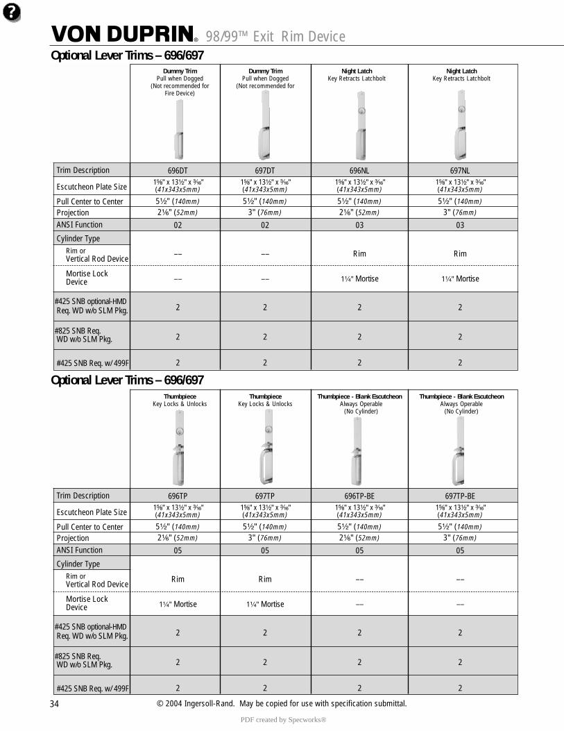
98/99™ Exit Rim Device
34 © 2004 Ingersoll-Rand. May be copied for use with specification submittal.
Dummy Trim Dummy Trim Night Latch Night LatchPull when Dogged Pull when Dogged Key Retracts Latchbolt Key Retracts Latchbolt
(Not recommended for (Not recommended for Fire Device) Fire Device)
Trim Description
Escutcheon Plate Size
Pull Center to CenterProjectionANSI Function
Cylinder TypeRim or Vertical Rod Device
Mortise Lock Device
#425 SNB optional-HMDReq. WD w/o SLM Pkg.
#825 SNB Req. WD w/o SLM Pkg.
#425 SNB Req. w/ 499F
696DT 697DT 696NL 697NL1⁵�₈" x 13¹�₂" x ³�₁₆" 1⁵�₈" x 13¹�₂" x ³�₁₆" 1⁵�₈" x 13¹�₂" x ³�₁₆" 1⁵�₈" x 13¹�₂" x ³�₁₆"(41x343x5mm) (41x343x5mm) (41x343x5mm) (41x343x5mm)
5¹�₂" (140mm) 5¹�₂" (140mm) 5¹�₂" (140mm) 5¹�₂" (140mm)2¹�₆" (52mm) 3" (76mm) 2¹�₆" (52mm) 3" (76mm)
02 02 03 03
–– –– Rim Rim
–– –– 1¹�₄" Mortise 1¹�₄" Mortise
2 2 2 2
2 2 2 2
2 2 2 2
Optional Lever Trims – 696/697
Thumbpiece Thumbpiece Thumbpiece - Blank Escutcheon Thumbpiece - Blank EscutcheonKey Locks & Unlocks Key Locks & Unlocks Always Operable Always Operable
(No Cylinder) (No Cylinder)Fire Device)
Trim Description
Escutcheon Plate Size
Pull Center to CenterProjectionANSI Function
Cylinder TypeRim or Vertical Rod Device
Mortise Lock Device
#425 SNB optional-HMDReq. WD w/o SLM Pkg.
#825 SNB Req. WD w/o SLM Pkg.
#425 SNB Req. w/ 499F
696TP 697TP 696TP-BE 697TP-BE1⁵�₈" x 13¹�₂" x ³�₁₆" 1⁵�₈" x 13¹�₂" x ³�₁₆" 1⁵�₈" x 13¹�₂" x ³�₁₆" 1⁵�₈" x 13¹�₂" x ³�₁₆"(41x343x5mm) (41x343x5mm) (41x343x5mm) (41x343x5mm)
5¹�₂" (140mm) 5¹�₂" (140mm) 5¹�₂" (140mm) 5¹�₂" (140mm)2¹�₆" (52mm) 3" (76mm) 2¹�₆" (52mm) 3" (76mm)
05 05 05 05
Rim Rim –– ––
1¹�₄" Mortise 1¹�₄" Mortise –– ––
2 2 2 2
2 2 2 2
2 2 2 2
Optional Lever Trims – 696/697
PDF created by Specworks®
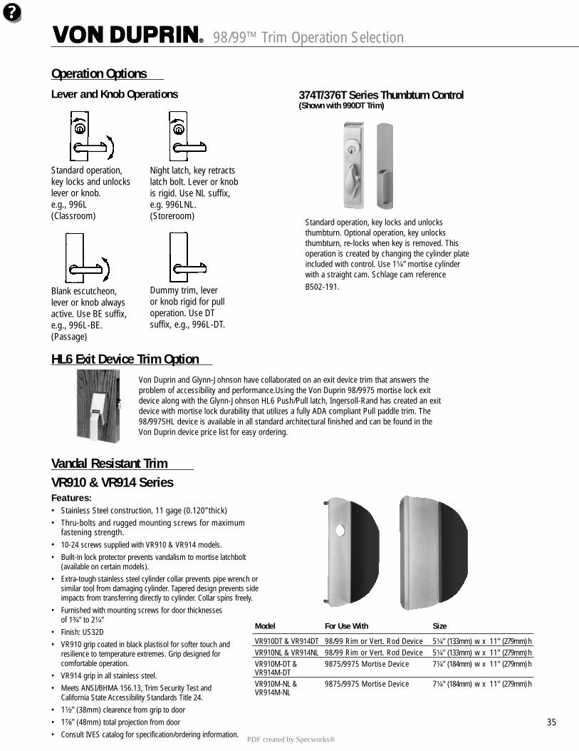
98/99™ Trim Operation Selection
35
Operation Options
HL6 Exit Device Trim Option
Vandal Resistant TrimVR910 & VR914 SeriesFeatures:• Stainless Steel construction, 11 gage (0.120" thick)• Thru-bolts and rugged mounting screws for maximum
fastening strength.• 10-24 screws supplied with VR910 & VR914 models.• Built-in lock protector prevents vandalism to mortise latchbolt
(available on certain models).• Extra-tough stainless steel cylinder collar prevents pipe wrench or
similar tool from damaging cylinder. Tapered design prevents side impacts from transferring directly to cylinder. Collar spins freely.
• Furnished with mounting screws for door thicknesses of 1³�₄" to 2¹�₄"
• Finish: US32D• VR910 grip coated in black plastisol for softer touch and
resilience to temperature extremes. Grip designed for comfortable operation.
• VR914 grip in all stainless steel.• Meets ANSI/BHMA 156.13, Trim Security Test and
California State Accessibility Standards Title 24.• 1¹�₂" (38mm) clearence from grip to door• 1⁷�₈" (48mm) total projection from door• Consult IVES catalog for specification/ordering information.
Standard operation, key locks and unlocksthumbturn. Optional operation, key unlocksthumbturn, re-locks when key is removed. Thisoperation is created by changing the cylinder plateincluded with control. Use 1¹�₄" mortise cylinderwith a straight cam. Schlage cam referenceB502-191.
Standard operation, key locks and unlockslever or knob.e.g., 996L(Classroom)
Night latch, key retractslatch bolt. Lever or knobis rigid. Use NL suffix,e.g. 996LNL.(Storeroom)
Blank escutcheon, lever or knob alwaysactive. Use BE suffix,e.g., 996L-BE.(Passage)
Dummy trim, lever or knob rigid for pull operation. Use DT suffix, e.g., 996L-DT.
Lever and Knob Operations 374T/376T Series Thumbturn Control(Shown with 990DT Trim)
Von Duprin and Glynn-Johnson have collaborated on an exit device trim that answers theproblem of accessibility and performance.Using the Von Duprin 98/9975 mortise lock exitdevice along with the Glynn-Johnson HL6 Push/Pull latch, Ingersoll-Rand has created an exitdevice with mortise lock durability that utilizes a fully ADA compliant Pull paddle trim. The98/9975HL device is available in all standard architectural finished and can be found in theVon Duprin device price list for easy ordering.
Model For Use With Size
VR910DT & VR914DT 98/99 Rim or Vert. Rod Device 5¹�₄" (133mm) w x 11" (279mm) hVR910NL & VR914NL 98/99 Rim or Vert. Rod Device 5¹�₄" (133mm) w x 11" (279mm) hVR910M-DT & 9875/9975 Mortise Device 7¹�₄" (184mm) w x 11" (279mm) hVR914M-DTVR910M-NL & 9875/9975 Mortise Device 7¹�₄" (184mm) w x 11" (279mm) hVR914M-NL
PDF created by Specworks®
5353535353
98/99™ Additional Information
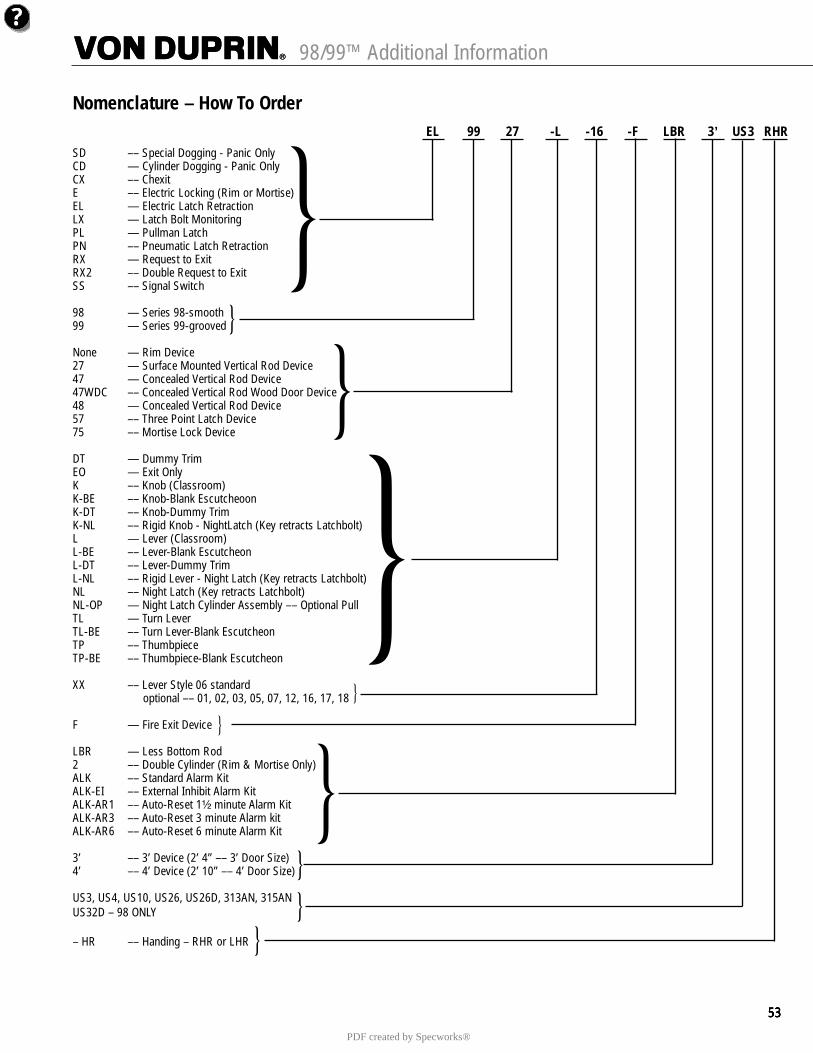
Nomenclature – How To Order
SD –– Special Dogging - Panic OnlyCD — Cylinder Dogging - Panic OnlyCX –– ChexitE –– Electric Locking (Rim or Mortise)EL — Electric Latch RetractionLX — Latch Bolt MonitoringPL — Pullman LatchPN –– Pneumatic Latch RetractionRX — Request to ExitRX2 –– Double Request to ExitSS –– Signal Switch
98 — Series 98-smooth99 — Series 99-grooved
None — Rim Device27 — Surface Mounted Vertical Rod Device47 — Concealed Vertical Rod Device47WDC –– Concealed Vertical Rod Wood Door Device48 — Concealed Vertical Rod Device57 –– Three Point Latch Device75 –– Mortise Lock Device
DT — Dummy TrimEO — Exit OnlyK –– Knob (Classroom)K-BE –– Knob-Blank EscutcheoonK-DT –– Knob-Dummy TrimK-NL –– Rigid Knob - NightLatch (Key retracts Latchbolt)L — Lever (Classroom)L-BE –– Lever-Blank EscutcheonL-DT –– Lever-Dummy TrimL-NL –– Rigid Lever - Night Latch (Key retracts Latchbolt)NL –– Night Latch (Key retracts Latchbolt)NL-OP — Night Latch Cylinder Assembly –– Optional PullTL — Turn LeverTL-BE –– Turn Lever-Blank EscutcheonTP –– ThumbpieceTP-BE –– Thumbpiece-Blank Escutcheon
XX –– Lever Style 06 standardoptional –– 01, 02, 03, 05, 07, 12, 16, 17, 18
F — Fire Exit Device
LBR — Less Bottom Rod2 –– Double Cylinder (Rim & Mortise Only)ALK –– Standard Alarm KitALK-EI –– External Inhibit Alarm KitALK-AR1 –– Auto-Reset 1¹�₂ minute Alarm KitALK-AR3 –– Auto-Reset 3 minute Alarm kitALK-AR6 –– Auto-Reset 6 minute Alarm Kit
3’ –– 3’ Device (2’ 4” –– 3’ Door Size)4’ –– 4’ Device (2’ 10” –– 4’ Door Size)
US3, US4, US10, US26, US26D, 313AN, 315ANUS32D – 98 ONLY
– HR –– Handing – RHR or LHR
EL 99 27 -L -16 -F LBR 3’ US3 RHR
PDF created by Specworks®
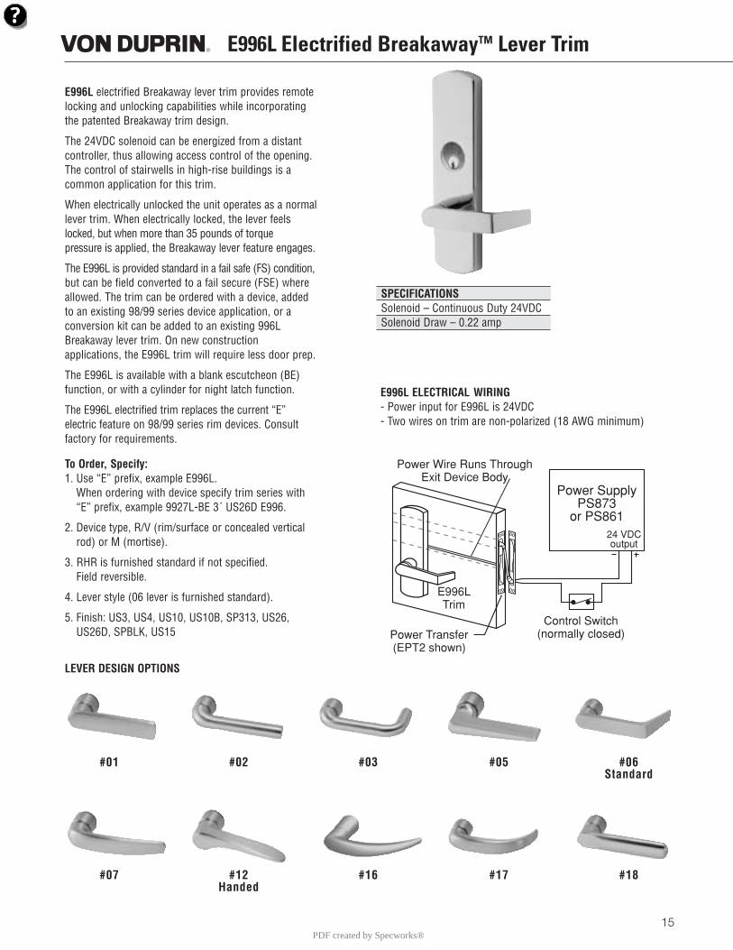
E996L electrified Breakaway lever trim provides remotelocking and unlocking capabilities while incorporatingthe patented Breakaway trim design.
The 24VDC solenoid can be energized from a distantcontroller, thus allowing access control of the opening.The control of stairwells in high-rise buildings is acommon application for this trim.
When electrically unlocked the unit operates as a normallever trim. When electrically locked, the lever feelslocked, but when more than 35 pounds of torque pressure is applied, the Breakaway lever feature engages.
The E996L is provided standard in a fail safe (FS) condition,but can be field converted to a fail secure (FSE) whereallowed. The trim can be ordered with a device, addedto an existing 98/99 series device application, or a conversion kit can be added to an existing 996LBreakaway lever trim. On new construction applications, the E996L trim will require less door prep.
The E996L is available with a blank escutcheon (BE)function, or with a cylinder for night latch function.
The E996L electrified trim replaces the current “E” electric feature on 98/99 series rim devices. Consultfactory for requirements.
To Order, Specify:1. Use “E” prefix, example E996L.
When ordering with device specify trim series with“E” prefix, example 9927L-BE 3´ US26D E996.
2. Device type, R/V (rim/surface or concealed verticalrod) or M (mortise).
3. RHR is furnished standard if not specified. Field reversible.
4. Lever style (06 lever is furnished standard).
5. Finish: US3, US4, US10, US10B, SP313, US26,US26D, SPBLK, US15
E996L Electrified BreakawayTM Lever Trim
15
E996L ELECTRICAL WIRING- Power input for E996L is 24VDC- Two wires on trim are non-polarized (18 AWG minimum)
LEVER DESIGN OPTIONS
SPECIFICATIONSSolenoid – Continuous Duty 24VDCSolenoid Draw – 0.22 amp
#01 #02 #03 #05 #06Standard
#07 #12 #16 #17 #18Handed
Power SupplyPS873
or PS861
Power Transfer(EPT2 shown)
Control Switch(normally closed)
24 VDCoutput
E996LTrim
Power Wire Runs ThroughExit Device Body
PDF created by Specworks®
Complete Padlock Cylinder OnlyConventional Primus Primus UL Conventional Primus Primus UL
PL1001 PL1741 PL1541
PL1002 PL1742 PL1542
PL1003 PL1743 PL1543
PL2001 PL2741 PL254147-410 47-740 47-540
PL2002 PL2742 PL2542
PL2003 PL2743 PL2543
PL3001 PL3741 PL3541
PL3002 PL3742 PL3542
10
C Y L I N D E R S , K E Y S A N D K E Y C O N T R O L
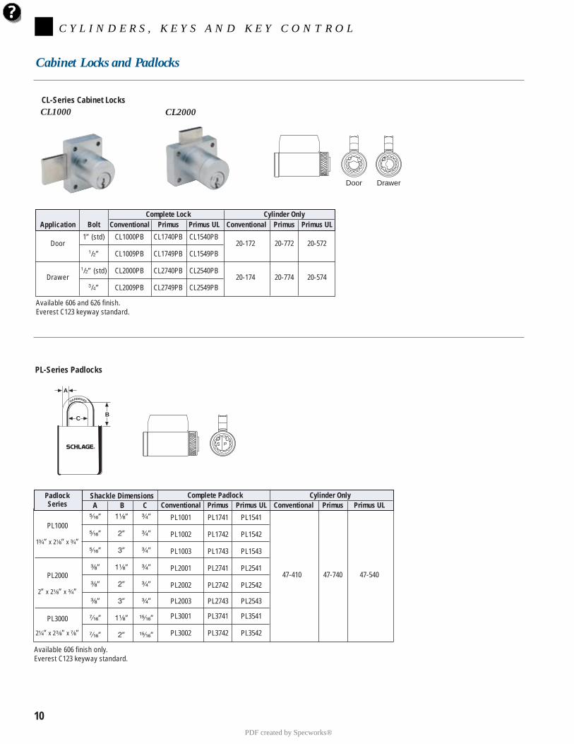
Cabinet Locks and Padlocks
PL-Series Padlocks
CL-Series Cabinet LocksCL1000 CL2000
Door Drawer
PadlockSeries
PL1000
1³⁄₄” x 2¹⁄₈” x ³⁄₄”
PL2000
2” x 2¹⁄₈” x ³⁄₄”
PL3000
2¹⁄₄” x 2³⁄₈” x ⁷⁄₈”
⁵⁄₁₆”
⁵⁄₁₆”
⁵⁄₁₆”
³⁄₈”
³⁄₈”
³⁄₈”
⁷⁄₁₆”
⁷⁄₁₆”
1¹⁄₈”
2”
3”
1¹⁄₈”
2”
3”
1¹⁄₈”
2”
³⁄₄”
³⁄₄”
³⁄₄”
³⁄₄”
³⁄₄”
³⁄₄”
¹⁵⁄₁₆”
¹⁵⁄₁₆”
Shackle DimensionsA B C
HARDENED
CB
A
Complete Lock Cylinder OnlyApplication Bolt Conventional Primus Primus UL Conventional Primus Primus UL
Door1” (std) CL1000PB CL1740PB CL1540PB
20-172 20-772 20-5721/2” CL1009PB CL1749PB CL1549PB
Drawer1/2” (std) CL2000PB CL2740PB CL2540PB
20-174 20-774 20-5743/4” CL2009PB CL2749PB CL2549PB
Available 606 and 626 finish.Everest C123 keyway standard.
Available 606 finish only.Everest C123 keyway standard.
PDF created by Specworks®
3
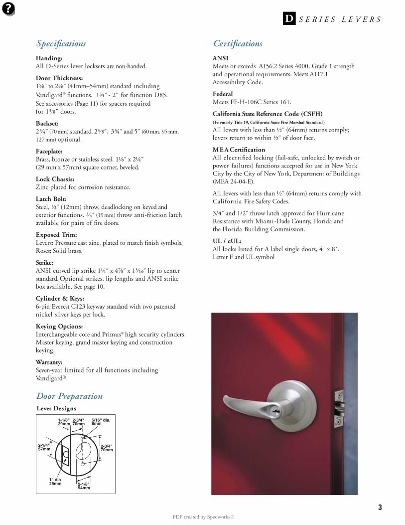
Specifications
Handing:All D-Series lever locksets are non-handed.
Door Thickness:1⅝˝ to 2⅛˝ (41mm–54mm) standard includingVandlgard® functions. 1¾˝ - 2˝ for function D85.See accessories (Page 11) for spacers required for 1³⁄ 8˝ doors.
Backset:2³⁄₄˝ (70mm) standard. 2³⁄ 8˝, 3¾˝ and 5˝ (60mm, 95mm,127mm) optional.
Faceplate:Brass, bronze or stainless steel. 1⅛˝ x 2¼˝(29 mm x 57mm) square corner, beveled.
Lock Chassis:Zinc plated for corrosion resistance.
Latch Bolt:Steel, ½˝ (12mm) throw, deadlocking on keyed andexterior functions. ³⁄₄˝ (19mm) throw anti-friction latchavailable for pairs of fire doors.
Exposed Trim:Levers: Pressure cast zinc, plated to match finish symbols.Roses: Solid brass.
Strike:ANSI curved lip strike 1¼˝ x 4⅞˝ x 1³⁄₁₆˝ lip to centerstandard. Optional strikes, lip lengths and ANSI strikebox available. See page 10.
Cylinder & Keys:6-pin Everest C123 keyway standard with two patentednickel silver keys per lock.
Keying Options:Interchangeable core and Primus® high security cylinders.Master keying, grand master keying and constructionkeying.
Warranty:Seven-year limited for all functions includingVandlgard®.
Certifications
ANSIMeets or exceeds A156.2 Series 4000, Grade 1 strengthand operational requirements. Meets A117.1Accessibility Code.
FederalMeets FF-H-106C Series 161.
California State Reference Code (CSFH)(Formerly Title 19, California State Fire Marshal Standard)
All levers with less than ½˝ (64mm) returns comply;levers return to within ½˝ of door face.
M E A CertificationAll electrified locking (fail-safe, unlocked by switch orpower failures) functions accepted for use in New YorkCity by the City of New York, Department of Buildings(MEA 24-04-E).
All levers with less than ½˝ (64mm) returns comply withCalifornia Fire Safety Codes.
3/4˝ and 1/2˝ throw latch approved for HurricaneResistance with Miami-Dade County, Florida and the Florida Building Commission.
UL / cUL:All locks listed for A label single doors, 4´ x 8´.Letter F and UL symbol
Door Preparation
2-1/4"57mm
2-3/4"70mm
5/16" dia.8mm
1" dia25mm 2-1/8"
54mm
1-1/8"29mm
2-3/4"70mm
Lever Designs
PDF created by Specworks®
4
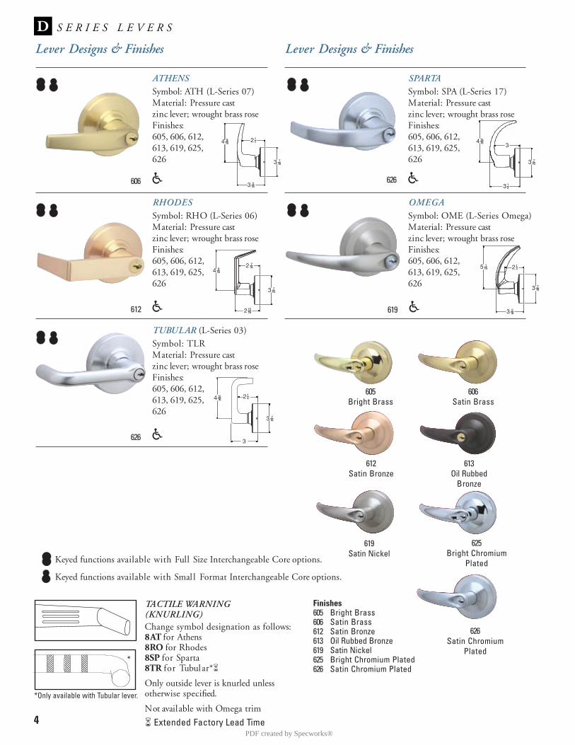
Lever Designs & Finishes
ATHENSSymbol: ATH (L-Series 07)Material: Pressure castzinc lever; wrought brass roseFinishes:605, 606, 612,613, 619, 625, 626
RHODESSymbol: RHO (L-Series 06)Material: Pressure castzinc lever; wrought brass roseFinishes:605, 606, 612,613, 619, 625, 626
SPARTA Symbol: SPA (L-Series 17)Material: Pressure castzinc lever; wrought brass roseFinishes:605, 606, 612, 613, 619, 625, 626
Lever Designs & Finishes
606
612
626
Finishes605 Bright Brass606 Satin Brass612 Satin Bronze613 Oil Rubbed Bronze619 Satin Nickel625 Bright Chromium Plated626 Satin Chromium Plated
Keyed functions available with Smal l Format Interchangeable Core options.
TACTILE WARNING(KNURLING)Change symbol designation as follows:8AT for Athens8RO for Rhodes8SP for Sparta8TR for Tubular*�
Only outside lever is knurled unless otherwise specified.
Not available with Omega trim
� Extended Factory Lead Time
OMEGASymbol: OME (L-Series Omega)Material: Pressure castzinc lever; wrought brass roseFinishes:605, 606, 612, 613, 619, 625, 626
605Bright Brass
606Satin Brass
612Satin Bronze
613Oil Rubbed
Bronze
619Satin Nickel
625Bright Chromium
Plated
626Satin Chromium
Plated
TUBULAR (L-Series 03)Symbol: TLRMaterial: Pressure castzinc lever; wrought brass roseFinishes:605, 606, 612,613, 619, 625, 626
626
619
Keyed functions available with Full Size Interchangeable Core options.
*Only available with Tubular lever.
*
PDF created by Specworks®
5D-Series Vandlgard levers comply with ADA requirements.
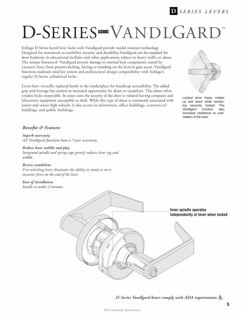
Schlage D-Series keyed lever locks with Vandlgard provide vandal resistant technology.Designed for maximum accessibility, security and durability, Vandlgard sets the standard fordoor hardware in educational facilities and other applications subject to heavy traffic or abuse.The unique features of Vandlgard prevent damage to internal lock components caused byexcessive force from persons kicking, hitting or standing on the lever to gain access. Vandlgardfunctions maintain total key system and architectural design compatibility with Schlage’sregular D-Series cylindrical locks.
Levers have virtually replaced knobs in the marketplace for handicap accessibility. The addedgrip and leverage has created an increased opportunity for abuse or vandalism. This abuse oftenrenders locks inoperable. In some cases the security of the door is violated leaving computer andlaboratory equipment susceptible to theft. While this type of abuse is commonly associated withjunior and senior high schools, it also occurs in universities, office buildings, commercia lbuildings, and public buildings.
D-SERIES VANDLGARD™WIT H
Inner spindle operatesindependently of lever when locked
Locked lever freely rotates up and down while remain-ing securely locked. TheVandlgard function alsoincreases resistance to over-rotation of the lever.
Benefits & Features
Superb warranty. All Vandlgard functions have a 7-year warranty.
Reduce lever wobble and play.Integrated spindle and spring cage greatly reduces lever sag andwobble.
Resists vandalism.Free-wheeling lever eliminates the ability to stand or exe rtexcessive force on the end of the leve r.
Ease of installation.Installs in under 2 minutes.
PDF created by Specworks®
6
FunctionsANSI A156.2 Series 4000 Grade 1
SCHLAGE ANSI
Non-Keyed Locks
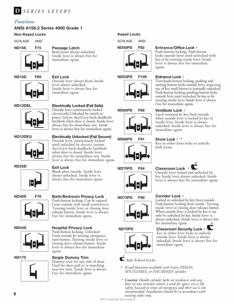
ND10S F75 Passage LatchBoth levers always unlocked.Inside lever is always free forimmediate egress.
ND50PD F82 Entrance/Office Lock †Push-button locking. Push-buttonlocks outside lever until unlocked withkey or by turning inside lever. Insidelever is always free for immediateegress.
ND53PD F109 Entrance Lock †Turn/push-button locking; pushing andturning button locks outside lever, requiringuse of key until button is manually unlocked.Push-button locking; pushing button locksoutside lever until unlocked by key or byturning inside lever. Inside lever is alwaysf ree for immediate egress.
ND60PD F88 Vestibule Lock †Latch retracted by key from outsidewhen outside lever is locked by key ininside lever. Inside lever is alwaysunlocked. Inside lever is always free forimmediate egress.
ND66PD F91 Store Lock † *Key in either lever locks or unlocksboth levers.
ND70PD F84 Classroom Lock †Outside lever locked and unlocked bykey. Inside lever always unlocked. Insidelever is always free for immediate egress.
ND73PD F90 Corridor Lock †Locked or unlocked by key from outside.Push-button locking from inside. Turninginside lever or closing door releases button.When outside lever is locked by key it canonly be unlocked by key. Inside lever isalways unlocked. Inside lever is always freefor immediate egress.
ND12D F89 Exit LockOutside lever always fixed. Insidelever always unlocked.Inside lever is always free forimmediate egress.
ND12DEL Electrically Locked (Fail Safe)Outside lever continuously lockedelectrically. Unlocked by switch orpower failure. Auxiliary latch deadlockslatchbolt when door is closed. Inside leveralways free for immediate exit. Insidelever is always free for immediate egress.
SCHLAGE ANSI
Keyed Locks
† Keyed functions available with 6-pin (PD/LD), SFIC(GD/BD), or FSIC(RD/JD) cylinder.
* Caution: Double cylinder locks on residences and anydoor in any structure which is used for egress are a lifesafety hazard in times of emergency and their use is notrecommended. Installation should be in accordance withexisting codes only.
Safe School Locks
ND12DEU Electrically Unlocked (Fail Secure)Outside lever continuously lockeduntil unlocked by electric current.Auxi l iary latch deadlocks latchboltwhen door is closed. Inside leveralways free for immediate exit. Insidelever is always free for immediate egress.
ND25D Exit LockBlank plate outside. Inside leveralways unlocked. Inside lever isalways free for immediate egress.
ND40S F76 Bath/Bedroom Privacy LockPush-button locking. Can be openedf rom outside with small screwdriver.Turning inside lever or closing doorreleases button. Inside lever is alwaysf ree for immediate egress.
ND44S Hospital Privacy LockPush-button locking. Unlockedf rom outside by turning emergencyturn-button. Turning inside lever orclosing door releases button. Insidelever is always free for immediateegress.
ND170 Single Dummy TrimDummy trim for one side of door.Used for door pull or as matchinginactive trim. Inside lever is alwaysf ree for immediate egress.
ND75PD Classroom Security Lock †Key in either lever locks or unlocksoutside lever. Inside lever is alwaysunlocked. Inside lever is always free forimmediate egress.
PDF created by Specworks®
7
FunctionsANSI A156.2 Series 4000 Grade 1
† Keyed functions available with 6-pin (PD/LD), SFIC(GD/BD), or FSIC(RD/JD) cylinders.
* Caution: Double cylinder locks on residences and anydoor in any structure which is used for egress are a lifesafety hazard in times of emergency and their use is notrecommended. Installation should be in accordance withexisting codes only.
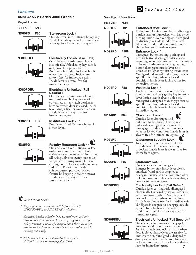
** 85 function locks are not available in Full Size & Small Format Interchangeable Cores.
ND80PD F86 Storeroom Lock †Outside lever fixed. Entrance by key only.Inside lever always unlocked. Inside leveris always free for immediate egress.
ND80PDEL Electrically Locked (Fail Safe) †Outside lever continuously lockedelectrically. Unlocked by key outsideor by switch or power failure.Auxi l iary latch deadlocks latchboltwhen door is closed. Inside leveralways free for immediate exit.Inside lever is always free forimmediate egress.
ND80PDEU Electrically Unlocked (FailSecure) †Outside lever continuously lockeduntil unlocked by key or electriccurrent. Auxi l iary latch deadlockslatchbolt when door is closed. Insidelever always free for immediate exit.Inside lever is always free forimmediate egress.
ND82PD F87 Institution Lock † *Both levers fixed. Entrance by key ineither lever.
SCHLAGE ANSI
Keyed Locks
ND91PD F82 Entrance/Office Lock †Push-button locking. Push-button disengagesoutside lever untilunlocked with key or byturning inside lever. Vandlgard is designedto disengage outside spindle from latchwhen in locked condition. Inside lever isalways free for immediate egress.
ND92PD F109 Entrance Lock †Turn/push-button locking; pushing andturning button disengages outside lever,requiring use of key until button is manuallyunlocked. Push-button locking; pushingbutton disengages outside lever untilunlocked by key or by turning inside lever.Vandlgard is designed to disengage outsidespindle from latch when in lockedcondition. Inside lever is always free forimmediate egress.
ND93PD F88 Vestibule Lock †Latch retracted by key from outside whenoutside lever is disengaged by key in insidelever. Inside lever is always unlocked.Vandlgard is designed to disengage outsidespindle from latch when in lockedcondition. Inside lever is always free forimmediate egress.
ND94PD F84 Classroom Lock †Outside lever disengaged andunlocked by key. Inside lever alwaysunlocked. Vandlgard is designed todisengage outside spindle from latchwhen in locked condition. Inside lever isalways free for immediate egress.
ND96PD F86 Storeroom Lock †Outside lever always disengaged.Entrance by key only. Inside lever alwaysunlocked. Vandlgard is designed todisengage outside spindle from latch whenin locked condition. Inside lever is alwaysf ree for immediate egress.
SCHLAGE ANSI
Vandlgard Functions
ND96PDEL Electrically Locked (Fail Safe) †Outside lever continuously disengagedelectrically. Unlocked by key outside or byswitch or power failure. Auxiliary latchdeadlocks latchbolt when door is closed.Inside lever always free for immediate exit.Vandlgard is designed to disengage outsidespindle from latch when in lockedcondition. Inside lever is always free forimmediate egress.
ND96PDEU Electrically Unlocked (Fail Secure) †Outside lever continuously disengaged.until unlocked by key or electric current.Auxiliary latch deadlocks latchbolt whendoor is closed. Inside lever always free forimmediate exit. Vandlgard is designed todisengage outside spindle from latch whenin locked condition. Inside lever is alwaysf ree for immediate egress.
ND85PD Faculty Restroom Lock **Outside lever fixed. Entrance by keyonly. Push-button in inside lever activates visual “occupancy” indicator,a l lowing only emergency master keyto operate. Turning inside lever orclosing door releases visualoccupancyindicator. Rotation of inside spinner-button provides lock-outfeature by keeping indicator thrown.Inside lever is always free forimmediate egress.
ND95PD Classroom Security Lock †Key in either lever locks or unlocksoutside lever. Inside lever is alwaysunlocked. Inside lever is always free forimmediate egress.
Safe School Locks
PDF created by Specworks®
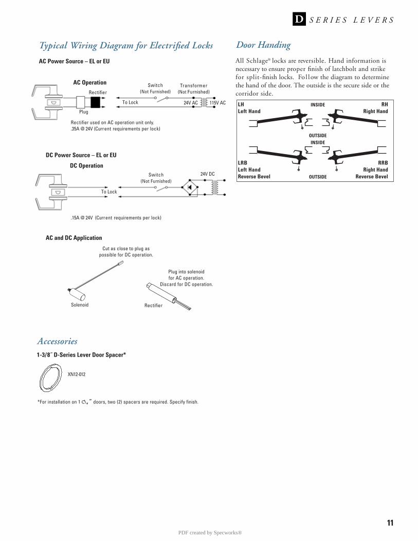
Door Handing
All Schlage® locks are reversible. Hand information isnecessary to ensure proper finish of latchbolt and strike for split-finish locks. Fo l low the diagram to determine the hand of the door. The outside is the secure side or thecorridor side.
LHLeft Hand
INSIDE
OUTSIDE
OUTSIDE
INSIDE
LRBLeft HandReverse Bevel
RHRight Hand
RRBRight Hand
Reverse Bevel
11
DC Power Source – EL or EU
Switch(Not Furnished)
Transformer(Not Furnished)
Typical Wiring Diagram for Electrified Locks
AC Operation
Rectifier
To Lock
Plug
Rectifier used on AC operation unit only..35A @ 24V (Current requirements per lock)
24V AC 115V AC
Switch(Not Furnished)
DC Operation
To Lock
.15A @ 24V (Current requirements per lock)
AC and DC Application
Solenoid Rectifier
Cut as close to plug aspossible for DC operation.
Plug into solenoid for AC operation.
Discard for DC operation.
24V DC
AC Power Source – EL or EU
1-3/8˝ D-Series Lever Door Spacer*
Accessories
XN12-012
*For installation on 1 C\,” doors, two (2) spacers are required. Specify finish.
PDF created by Specworks®
PS-4
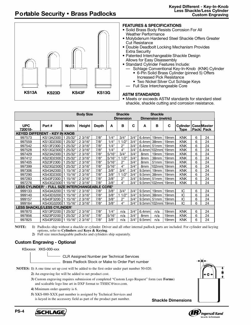
F E AT U R E S & S P E C I F I C AT I O N S• Solid Brass Body Resists Corrosion For All
Weather Perf o rm a n c e• Molybdenum Hardened Steel Shackle Offers Greater
Cut Resistance• Double Deadbolt Locking Mechanism Provides
Extra Security• Patented Interchangeable Shackle Design
Allows for Easy Disassembly• S t a n d a rd Cylinder Features Include:
— Schlage Conventional Key-In-Knob (KNK) Cylinder• 6-Pin Solid Brass Cylinder (pinned 5) Offers
I n c reased Pick Resistance• Two Nickel Silver Cut Schlage Keys
— Full Size Interchangeable Core
ASTM STA N D A R D S• Meets or exceeds ASTM standards for standard steel
shackle, shackle cutting and corrosion resistance.
Shackle Dimensions
Body Size S h a c k l e S h a c k l e
D i m e n s i o n Dimension (metric)
U P C P a rt # Wi d t h H e i g h t D e p t h A B C A B C C y l i n d e r Case M a s t e r7 2 0 0 1 8 - Ty p e P a c k P a c k
KEYED DIFFERENT - KEY I N K N O B
9 9 7 5 7 3 KS13A2300 1 25/32" 2 3/16" 7 / 8 " 1 / 4 " 3 / 4 " 3 / 4 " 6 . 4 m m 1 9 m m 1 9 m m K N K 6 2 4
9 9 7 5 5 9 KS13D2300 1 25/32" 2 3/16" 7 / 8 " 1 / 4 " 1 1/2" 3 / 4 " 6 . 4 m m 3 8 m m 1 9 m m K N K 6 2 4
9 9 7 5 4 2 KS13F2300 1 25/32" 2 3/16" 7 / 8 " 1 / 4 " 2 " 3 / 4 " 6 . 4 m m 5 1 m m 1 9 m m K N K 6 2 49 9 7 5 2 8 K S 1 3 G 2 3 0 0 1 25/32" 2 3/16" 7 / 8 " 1 / 4 " 4 " 3 / 4 " 6 . 4 m m 1 0 2 m m 1 9 m m K N K 6 2 4
9 9 7 4 2 9 KS23A2300 1 25/32" 2 3/16" 7 / 8 " 5 / 1 6 " 3 / 4 " 3 / 4 " 8 m m 1 9 m m 1 9 m m K N K 6 2 4
9 9 7 4 1 2 KS23D2300 1 25/32" 2 3/16" 7 / 8 " 5 / 1 6 " 1 1/2" 3 / 4 " 8 m m 3 8 m m 1 9 m m K N K 6 2 49 9 7 4 0 5 KS23F2300 1 25/32" 2 3/16" 7 / 8 " 5 / 1 6 " 2 " 3 / 4 " 8 m m 5 1 m m 1 9 m m K N K 6 2 4
9 9 7 3 9 9 KS23G2300 1 25/32" 2 3/16" 7 / 8 " 5 / 1 6 " 4 " 3 / 4 " 8 m m 1 0 2 m m 1 9 m m K N K 6 2 4
9 9 7 3 0 6 KS43A2300 1 15/16" 2 3/16" 7 / 8 " 3 / 8 " 3 / 4 " 3 / 4 " 9 . 5 m m 1 9 m m 1 9 m m K N K 6 2 49 9 7 2 9 0 KS43D2300 1 15/16" 2 3/16" 7 / 8 " 3 / 8 " 1 1/2" 3 / 4 " 9 . 5 m m 3 8 m m 1 9 m m K N K 6 2 4
9 9 7 2 8 3 K S 4 3 F 2 3 0 0 1 15/16" 2 3/16" 7 / 8 " 3 / 8 " 2 " 3 / 4 " 9 . 5 m m 5 1 m m 1 9 m m K N K 6 2 4
9 9 7 2 7 6 KS43G2300 1 15/16" 2 3/16" 7 / 8 " 3 / 8 " 4 " 3 / 4 " 9 . 5 m m 1 0 2 m m 1 9 m m K N K 6 2 4L E S S C Y L I N D E R1 - FULL SIZE INTERCHANGEABLE CORE2
9 9 9 1 3 3 K S 4 3 A 3 2 0 0 1 15/16" 2 3/16" 7 / 8 " 3 / 8 " 3 / 4 " 3 / 4 " 9 . 5 m m 1 9 m m 1 9 m m I C 6 2 4
9 9 9 1 4 0 K S 4 3 D 3 2 0 0 1 15/16" 2 3/16" 7 / 8 " 3 / 8 " 1 1/2" 3 / 4 " 9 . 5 m m 3 8 m m 1 9 m m I C 6 2 49 9 9 1 5 7 K S 4 3 F 3 2 0 0 1 15/16" 2 3/16" 7 / 8 " 3 / 8 " 2 " 3 / 4 " 9 . 5 m m 5 1 m m 1 9 m m I C 6 2 4
9 9 9 1 6 4 K S 4 3 G 3 2 0 0 1 15/16" 2 3/16" 7 / 8 " 3 / 8 " 4 " 3 / 4 " 9 . 5 m m 1 0 2 m m 1 9 m m I C 6 2 4
L E S S S H A C K L E / L E S S C Y L I N D E R1
9 9 7 8 7 0 KS13P2200 1 25/32" 2 3/16" 7 / 8 " 1 / 4 " n / a 3 / 4 " 6 . 4 m m n / a 1 9 m m K N K 6 24
9 9 7 8 5 6 KS23P2200 1 25/32" 2 3/16" 7 / 8 " 5 / 1 6 " n / a 3 / 4 " 8 m m n / a 1 9 m m K N K 6 2 4
9 9 7 8 2 5 KS43P2200 1 15/16" 2 3/16" 7 / 8 " 3 / 8 " n / a 3 / 4 " 9 . 5 m m n / a 1 9 m m K N K 6 2 4
NOTE: 1) Padlocks ship without a shackle or cylinder. Driver and all other internal padlock parts are included. For cylinder and keyingoptions, refer to Cylinders and Keys & Keying.
2) Full size interchangeable padlocks and cylinders ship separately.
NOTES: 1) A one time set up cost will be added to the first order under part number 50-020.
2) An engraving fee will be added to net product cost.
3) Custom engraving requires submission of completed “Custom Logo Request” form (see Forms)and scaleable logo line art in DXF format to [email protected].
4) Minimum order quantity is 6.
5) XKS-000-XXX part number is assigned by Technical Services and is keyed in the accessory field as part of the product part number.
Custom Engraving - Optional
K S x x x x x X K S - 0 0 0 - x x x
CLR Assigned Number per Technical Services
Brass Padlock Stock or Make to Order Part number
KS13A KS23D KS43F KS13G
Keyed Different - Key-In-Knob Less Shackle/Less Cylinder
Custom EngravingP o rtable Security • Brass Padlocks
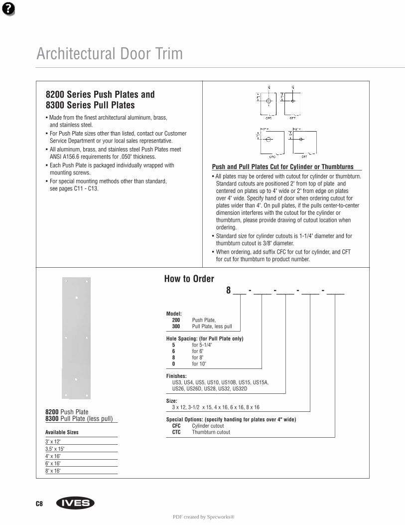
C8
Architectural Door Trim
How to Order8 ___ - ____ -____ - ____ - ____
Model: 200 Push Plate, 300 Pull Plate, less pull
Hole Spacing: (for Pull Plate only)5 for 5-1/4"6 for 6" 8 for 8"0 for 10"
Finishes: US3, US4, US5, US10, US10B, US15, US15A, US26, US26D, US28, US32, US32D
Size: 3 x 12, 3-1/2 x 15, 4 x 16, 6 x 16, 8 x 16
Special Options: (specify handing for plates over 4" wide)CFC Cylinder cutoutCTC Thumbturn cutout
8200 Series Push Plates and 8300 Series Pull Plates• Made from the finest architectural aluminum, brass,
and stainless steel.• For Push Plate sizes other than listed, contact our Customer
Service Department or your local sales representative.• All aluminum, brass, and stainless steel Push Plates meet
ANSI A156.6 requirements for .050" thickness.• Each Push Plate is packaged individually wrapped with
mounting screws.• For special mounting methods other than standard,
see pages C11 - C13.
8200 Push Plate8300 Pull Plate (less pull)
Available Sizes
3" x 12"3.5" x 15"4" x 16"6" x 16"8" x 16"
Push and Pull Plates Cut for Cylinder or Thumbturns• All plates may be ordered with cutout for cylinder or thumbturn.
Standard cutouts are positioned 2" from top of plate and centered on plates up to 4" wide or 2" from edge on plates over 4" wide. Specify hand of door when ordering cutout forplates wider than 4". On pull plates, if the pulls center-to-centerdimension interferes with the cutout for the cylinder or thumbturn, please provide drawing of cutout location whenordering.
• Standard size for cylinder cutouts is 1-1/4" diameter and forthumbturn cutout is 3/8" diameter.
• When ordering, add suffix CFC for cut for cylinder, and CFT for cut for thumbturn to product number.
PDF created by Specworks®
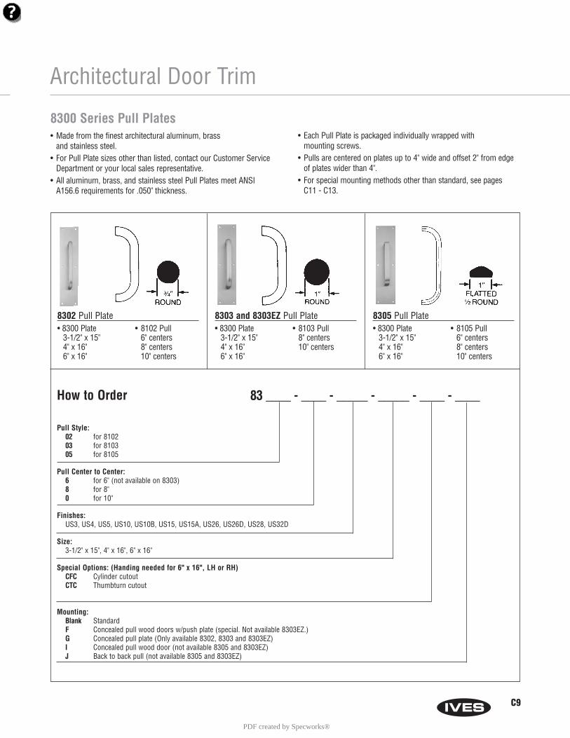
How to Order 83 ____ - ____ - _____ - _____ - ____ - ____
Pull Style:02 for 810203 for 810305 for 8105
Pull Center to Center: 6 for 6" (not available on 8303) 8 for 8"0 for 10"
Finishes: US3, US4, US5, US10, US10B, US15, US15A, US26, US26D, US28, US32D
Size:3-1/2" x 15", 4" x 16", 6" x 16"
Special Options: (Handing needed for 6" x 16", LH or RH)CFC Cylinder cutoutCTC Thumbturn cutout
Mounting: Blank Standard F Concealed pull wood doors w/push plate (special. Not available 8303EZ.)G Concealed pull plate (Only available 8302, 8303 and 8303EZ)I Concealed pull wood door (not available 8305 and 8303EZ)J Back to back pull (not available 8305 and 8303EZ)
Architectural Door Trim
• 8300 Plate3-1/2" x 15"4" x 16"6" x 16"
• 8102 Pull6" centers8" centers10" centers
8302 Pull Plate• 8300 Plate
3-1/2" x 15"4" x 16"6" x 16"
• 8103 Pull8" centers10" centers
8303 and 8303EZ Pull Plate• 8300 Plate
3-1/2" x 15"4" x 16"6" x 16"
• 8105 Pull6" centers8" centers10" centers
8305 Pull Plate
8300 Series Pull Plates• Made from the finest architectural aluminum, brass
and stainless steel.• For Pull Plate sizes other than listed, contact our Customer Service
Department or your local sales representative.• All aluminum, brass, and stainless steel Pull Plates meet ANSI
A156.6 requirements for .050" thickness.
• Each Pull Plate is packaged individually wrapped with mounting screws.
• Pulls are centered on plates up to 4" wide and offset 2" from edgeof plates wider than 4".
• For special mounting methods other than standard, see pages C11 - C13.
C9
PDF created by Specworks®
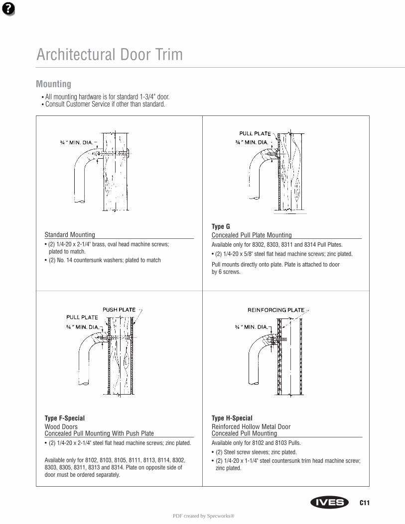
C11
Architectural Door Trim
Type F-SpecialWood DoorsConcealed Pull Mounting With Push Plate• (2) 1/4-20 x 2-1/4" steel flat head machine screws; zinc plated.
Available only for 8102, 8103, 8105, 8111, 8113, 8114, 8302, 8303, 8305, 8311, 8313 and 8314. Plate on opposite side of door must be ordered separately.
Standard Mounting• (2) 1/4-20 x 2-1/4" brass, oval head machine screws;
plated to match.• (2) No. 14 countersunk washers; plated to match
Type GConcealed Pull Plate MountingAvailable only for 8302, 8303, 8311 and 8314 Pull Plates.
• (2) 1/4-20 x 5/8" steel flat head machine screws; zinc plated.
Pull mounts directly onto plate. Plate is attached to door by 6 screws.
Type H-Special Reinforced Hollow Metal Door Concealed Pull MountingAvailable only for 8102 and 8103 Pulls.
• (2) Steel screw sleeves; zinc plated.• (2) 1/4-20 x 1-1/4" steel countersunk trim head machine screw;
zinc plated.
Mounting• All mounting hardware is for standard 1-3/4" door.• Consult Customer Service if other than standard.
PDF created by Specworks®
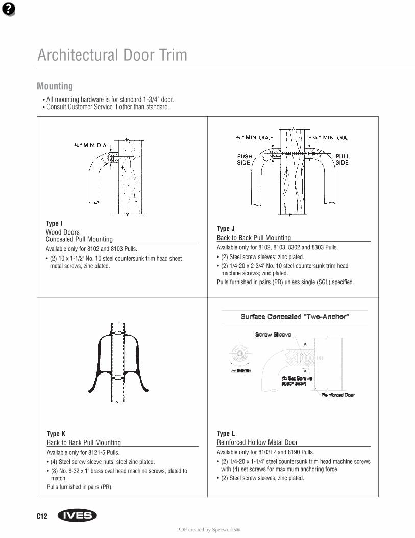
C12
Architectural Door Trim
Type KBack to Back Pull MountingAvailable only for 8121-5 Pulls.
• (4) Steel screw sleeve nuts; steel zinc plated.• (8) No. 8-32 x 1" brass oval head machine screws; plated to
match.Pulls furnished in pairs (PR).
Type IWood DoorsConcealed Pull MountingAvailable only for 8102 and 8103 Pulls.
• (2) 10 x 1-1/2" No. 10 steel countersunk trim head sheet metal screws; zinc plated.
Type JBack to Back Pull MountingAvailable only for 8102, 8103, 8302 and 8303 Pulls.
• (2) Steel screw sleeves; zinc plated.• (2) 1/4-20 x 2-3/4" No. 10 steel countersunk trim head
machine screws; zinc plated.Pulls furnished in pairs (PR) unless single (SGL) specified.
Mounting• All mounting hardware is for standard 1-3/4" door.• Consult Customer Service if other than standard.
Type LReinforced Hollow Metal DoorAvailable only for 8103EZ and 8190 Pulls.
• (2) 1/4-20 x 1-1/4" steel countersunk trim head machine screwswith (4) set screws for maximum anchoring force
• (2) Steel screw sleeves; zinc plated.
PDF created by Specworks®
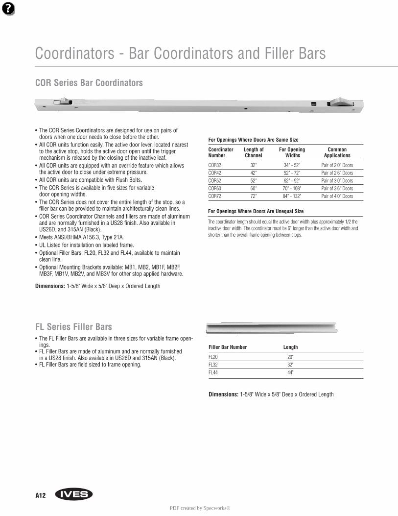
A12
Coordinators - Bar Coordinators and Filler Bars
• The COR Series Coordinators are designed for use on pairs ofdoors when one door needs to close before the other.
• All COR units function easily. The active door lever, located nearestto the active stop, holds the active door open until the triggermechanism is released by the closing of the inactive leaf.
• All COR units are equipped with an override feature which allowsthe active door to close under extreme pressure.
• All COR units are compatible with Flush Bolts. • The COR Series is available in five sizes for variable
door opening widths.• The COR Series does not cover the entire length of the stop, so a
filler bar can be provided to maintain architecturally clean lines. • COR Series Coordinator Channels and fillers are made of aluminum
and are normally furnished in a US28 finish. Also available inUS26D, and 315AN (Black).
• Meets ANSI/BHMA A156.3, Type 21A.• UL Listed for installation on labeled frame.• Optional Filler Bars: FL20, FL32 and FL44, available to maintain
clean line.• Optional Mounting Brackets available: MB1, MB2, MB1F, MB2F,
MB3F, MB1V, MB2V, and MB3V for other stop applied hardware.
COR Series Bar Coordinators
For Openings Where Doors Are Same Size
Coordinator Length of For Opening CommonNumber Channel Widths Applications
COR32 32" 34" - 52" Pair of 2'0" DoorsCOR42 42" 52" - 72" Pair of 2'6" DoorsCOR52 52" 62" - 92" Pair of 3'0" DoorsCOR60 60" 70" - 108" Pair of 3'6" DoorsCOR72 72" 84" - 132" Pair of 4'0" Doors
Filler Bar Number Length
FL20 20"FL32 32"FL44 44"
Dimensions: 1-5/8" Wide x 5/8" Deep x Ordered Length
For Openings Where Doors Are Unequal Size
The coordinator length should equal the active door width plus approximately 1/2 theinactive door width. The coordinator must be 6" longer than the active door width andshorter than the overall frame opening between stops.
FL Series Filler Bars• The FL Filler Bars are available in three sizes for variable frame open-
ings.• FL Filler Bars are made of aluminum and are normally furnished
in a US28 finish. Also available in US26D and 315AN (Black).• FL Filler Bars are field sized to frame opening.
Dimensions: 1-5/8" Wide x 5/8" Deep x Ordered Length
PDF created by Specworks®
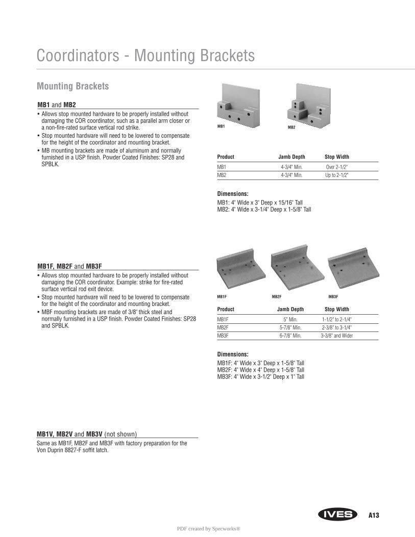
A13
Coordinators - Mounting Brackets
MB1 and MB2• Allows stop mounted hardware to be properly installed without
damaging the COR coordinator, such as a parallel arm closer or a non-fire-rated surface vertical rod strike.
• Stop mounted hardware will need to be lowered to compensate for the height of the coordinator and mounting bracket.
• MB mounting brackets are made of aluminum and normally furnished in a USP finish. Powder Coated Finishes: SP28 andSPBLK.
MB1F, MB2F and MB3F• Allows stop mounted hardware to be properly installed without
damaging the COR coordinator. Example: strike for fire-rated surface vertical rod exit device.
• Stop mounted hardware will need to be lowered to compensate for the height of the coordinator and mounting bracket.
• MBF mounting brackets are made of 3/8" thick steel and normally furnished in a USP finish. Powder Coated Finishes: SP28and SPBLK.
MB1V, MB2V and MB3V (not shown)Same as MB1F, MB2F and MB3F with factory preparation for the Von Duprin 8827-F soffit latch.
Mounting Brackets
MB1 MB2
MB1F MB2F MB3F
Product Jamb Depth Stop Width
MB1 4-3/4" Min. Over 2-1/2"MB2 4-3/4" Min. Up to 2-1/2"
Dimensions: MB1: 4" Wide x 3" Deep x 15/16" TallMB2: 4" Wide x 3-1/4" Deep x 1-5/8" Tall
Product Jamb Depth Stop Width
MB1F 5" Min. 1-1/2" to 2-1/4"MB2F 5-7/8" Min. 2-3/8" to 3-1/4"MB3F 6-7/8" Min. 3-3/8" and Wider
Dimensions: MB1F: 4" Wide x 3" Deep x 1-5/8" TallMB2F: 4" Wide x 4" Deep x 1-5/8" TallMB3F: 4" Wide x 3-1/2" Deep x 1" Tall
PDF created by Specworks®
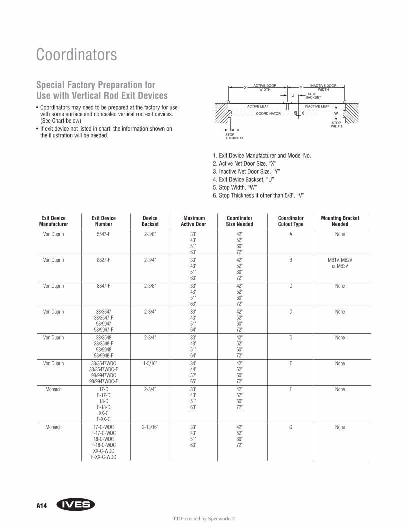
Exit Device Exit Device Device Maximum Coordinator Coordinator Mounting BracketManufacturer Number Backset Active Door Size Needed Cutout Type Needed
Von Duprin 5547-F 2-3/8" 33" 42" A None43" 52"51" 60"63" 72"
Von Duprin 8827-F 2-3/4" 33" 42" B MB1V, MB2V43" 52" or MB3V51" 60"63" 72"
Von Duprin 8847-F 2-3/8" 33" 42" C None43" 52"51" 60"63" 72"
Von Duprin 33/3547 2-3/4" 33" 42" D None33/3547-F 43" 52"98/9947 51" 60"
98/9947-F 64" 72"Von Duprin 33/3548 2-3/4" 33" 42" D None
33/3548-F 43" 52"98/9948 51" 60"
98/9948-F 64" 72"Von Duprin 33/3547WDC 1-5/16" 34" 42" E None
33/3547WDC-F 44" 52"98/9947WDC 52" 60"
98/9947WDC-F 65" 72"Monarch 17-C 2-3/4" 33" 42" F None
F-17-C 43" 52"18-C 51" 60"
F-18-C 63" 72"XX-C
F-XX-CMonarch 17-C-WDC 2-13/16" 33" 42" G None
F-17-C-WDC 43" 52"18-C-WDC 51" 60"
F-18-C-WDC 63" 72"XX-C-WDC
F-XX-C-WDC
A14
Coordinators
Special Factory Preparation for Use with Vertical Rod Exit Devices• Coordinators may need to be prepared at the factory for use
with some surface and concealed vertical rod exit devices. (See Chart below)
• If exit device not listed in chart, the information shown on the illustration will be needed.
1. Exit Device Manufacturer and Model No.2. Active Net Door Size, “X”3. Inactive Net Door Size, “Y”4. Exit Device Backset, “U”5. Stop Width, “W”6. Stop Thickness if other than 5/8", “V”
PDF created by Specworks®
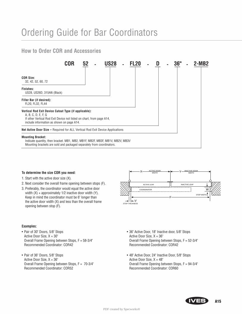
A15
Ordering Guide for Bar Coordinators
To determine the size COR you need:
1. Start with the active door size (X).2. Next consider the overall frame opening between stops (F). 3. Preferably, the coordinator would equal the active door
width (X) + approximately 1/2 inactive door width (Y). Keep in mind the coordinator must be 6" longer than the active door width (X) and less than the overall frame opening between stop (F).
Examples:
• Pair of 30" Doors, 5/8" Stops Active Door Size, X = 30"Overall Frame Opening between Stops, F = 58-3/4"Recommended Coordinator: COR42
• Pair of 36" Doors, 5/8" StopsActive Door Size, X = 36"Overall Frame Opening between Stops, F = 70-3/4"Recommended Coordinator: COR52
COORDINATOR
ACTIVE LEAF INACTIVE LEAF
ACTIVE DOORWIDTH
INACTIVE DOORWIDTH
X Y
W
VSTOP THICKNESS
STOP WIDTH
F
COR 52 US28 FL20 D 36" 2-MB2__ - ____ - ____ - __ - __ - _____
How to Order COR and Accessories
COR Size: 32, 42, 52, 60, 72
Finishes: US28, US26D, 315AN (Black)
Filler Bar (if desired): FL20, FL32, FL44
Vertical Rod Exit Device Cutout Type (if applicable): A, B, C, D, E, F, GIf other Vertical Rod Exit Device not listed on chart, from page A14,include information as shown on page A14.
Net Active Door Size – Required for ALL Vertical Rod Exit Device Applications
Mounting Bracket:Indicate quantity, then bracket. MB1, MB2, MB1F, MB2F, MB3F, MB1V, MB2V, MB3VMounting brackets are sold and packaged separately from coordinators.
• 36" Active Door, 18" Inactive door, 5/8" StopsActive Door Size, X = 36"Overall Frame Opening between Stops, F = 52-3/4"Recommended Coordinator: COR42
• 48" Active Door, 24" Inactive Door, 5/8" StopsActive Door Size, X = 48"Overall Frame Opening between Stops, F = 94-3/4"Recommended Coordinator: COR60
PDF created by Specworks®
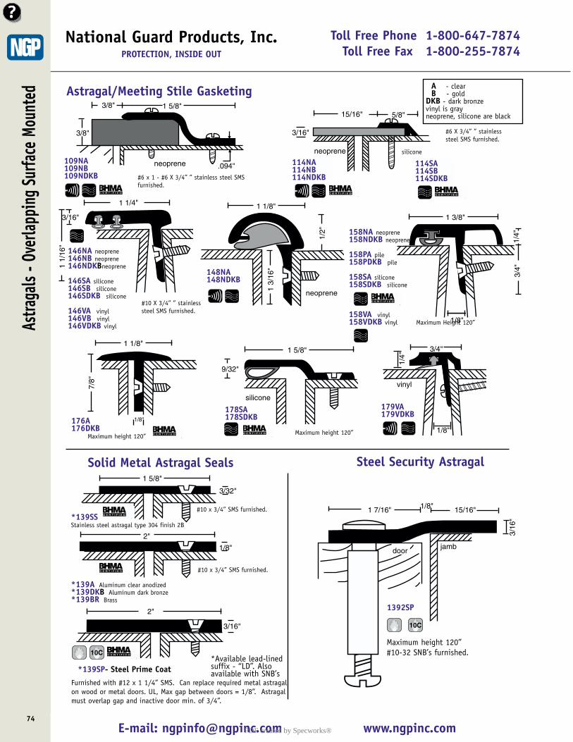
Toll Free Phone 1-800-647-7874Toll Free Fax 1-800-255-7874
E-mail: [email protected] www.ngpinc.com74
National Guard Products, Inc.PROTECTION, INSIDE OUT
Solid Metal Astragal Seals
Astra
gals
- Ove
rlapp
ing
Surfa
ce M
ount
ed
neoprene .094"
1 5/8"
3/8"
3/8"
3/16"
5/8"
neoprene
15/16"
1 5/8"
9/32"
silicone
109NA109NB109NDKB
114NA114NB114NDKB
178SA178SDKB
Maximum height 120”
A - clear B - gold
DKB - dark bronzevinyl is grayneoprene, silicone are black
Astragal/Meeting Stile Gasketing
#6 x 1 - #6 X 3/4” ” stainless steel SMSfurnished.
#6 X 3/4” ” stainlesssteel SMS furnished.
1/2"
1 1/8"
1 3/
16"
neoprene
148NA148NDKB
1 1/
16"
1 1/4"
3/16"
146NA neoprene146NB neoprene146NDKBneoprene
146SA silicone146SB silicone146SDKB silicone
146VA vinyl146VB vinyl146VDKB vinyl
#10 X 3/4” ” stainlesssteel SMS furnished.
1 3/8"
3/4"
1/4"
1/8"
158NA neoprene158NDKB neoprene
158PA pile158PDKB pile
158SA silicone158SDKB silicone
158VA vinyl158VDKB vinyl Maximum Height 120”
1 1/8"
7/8"
1/8"176A176DKB
Maximum height 120”
3/4"
1/4"
vinyl
1/8"
179VA179VDKB
1 5/8"
3/32"
*139SSStainless steel astragal type 304 finish 2B
2"
1/8"
*139A Aluminum clear anodized*139DKB Aluminum dark bronze *139BR Brass
2"
3/16"
3/16
"1 7/16"
jambdoor
15/16"1/8"
1392SP
Steel Security Astragal
*Available lead-linedsuffix - “LD”. Alsoavailable with SNB’s
10C
10C
Maximum height 120”#10-32 SNB’s furnished.
*139SP- Steel Prime Coat
#10 x 3/4” SMS furnished.
#10 x 3/4” SMS furnished.
silicone
114SA114SB114SDKB
Furnished with #12 x 1 1/4” SMS. Can replace required metal astragalon wood or metal doors. UL, Max gap between doors = 1/8”. Astragalmust overlap gap and inactive door min. of 3/4”.
PDF created by Specworks®
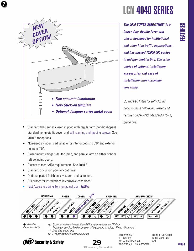
4040-1
PHONE 815-875-3311FAX 815-879-14974/00
LCN DIVISIONP.O. BOX 100121 W. RAILROAD AVE.PRINCETON, IL, USA 61356-0100
Standard 4040 series closer shipped with regular arm (non-hold-open),
standard non-metallic cover, and self reaming and tapping screws. See
4040-6 for options.
Non-sized cylinder is adjustable for interior doors to 5’0” and exterior
doors to 4’0”.
Closer mounts hinge side, top jamb, and parallel arm on either right or
left swinging doors.
Closers to meet ADA requirements. See 4040-8.
Standard or custom powder coat finish.
Optional plated finish on cover, arm, and fasteners.
SRI primer for installations in corrosive conditions.
Fast Accurate Spring Tension adjust dial. NEW!
The 4040 SUPER SMOOTHEE® is a
heavy duty, double lever arm
closer designed for institutional
and other high traffic applications,
and has passed 10,000,000 cycles
in independent testing. The wide
choice of options, installation
accessories and ease of
installation offer maximum
versatility.
UL and ULC listed for self-closing
doors without hold-open. Tested and
certified under ANSI Standard A156.4,
grade one.
FEATU
RES
LCN 4040 SERIES
HINGE SID
E
TOP JAMB
PARALLEL A
RM
POWDER COAT
PLATED
MOUNTING FINISH
NON-METALL
IC
METAL
DESIGNER M
ETALNEW
!COVER
REGULAR
HOLD-O
PEN
FUSIB
LE LI
NK
ARM FUNCTION*
EXTRA DUTY**
NON-HANDED
NON-SIZED
ACCESSIBILI
TY
DELAY ACTIO
N
CYLINDER
AVB
120° 120° 180° 10yr NRCUSH-N
-STOP**
WARRANTY
MAINTENANCE
110°
Available Not available
Closer available with less than 5.0 lbs. opening force on 36" door.* Maximum opening/hold-open point with standard template. Hinge side mount.** Stop side mount onlyNR = No periodic maintenance required.
29
NEWCOVER
OPTION!
Fast accurate installation
New Stick-on template
Optional designer series metal cover
PDF created by Specworks®
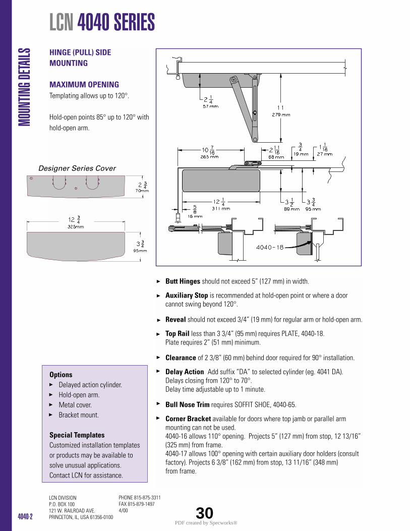
4040-2
PHONE 815-875-3311FAX 815-879-14974/00
LCN DIVISIONP.O. BOX 100121 W. RAILROAD AVE.PRINCETON, IL, USA 61356-0100
HINGE (PULL) SIDEMOUNTING
MAXIMUM OPENINGTemplating allows up to 120°.
Hold-open points 85° up to 120° withhold-open arm.
LCN 4040 SERIES
Butt Hinges should not exceed 5” (127 mm) in width.
Auxiliary Stop is recommended at hold-open point or where a door cannot swing beyond 120°.
Reveal should not exceed 3/4” (19 mm) for regular arm or hold-open arm.
Top Rail less than 3 3/4” (95 mm) requires PLATE, 4040-18. Plate requires 2” (51 mm) minimum.
Clearance of 2 3/8” (60 mm) behind door required for 90° installation.
Delay Action Add suffix “DA” to selected cylinder (eg. 4041 DA). Delays closing from 120° to 70°. Delay time adjustable up to 1 minute.
Bull Nose Trim requires SOFFIT SHOE, 4040-65.
Corner Bracket available for doors where top jamb or parallel arm mounting can not be used. 4040-16 allows 110° opening. Projects 5” (127 mm) from stop, 12 13/16” (325 mm) from frame. 4040-17 allows 100° opening with certain auxiliary door holders (consult factory). Projects 6 3/8” (162 mm) from stop, 13 11/16” (348 mm) from frame.
MOUN
TING D
ETAILS
OptionsDelayed action cylinder.Hold-open arm.Metal cover.Bracket mount.
Special Templates Customized installation templatesor products may be available tosolve unusual applications.Contact LCN for assistance.
30
Designer Series Cover
PDF created by Specworks®
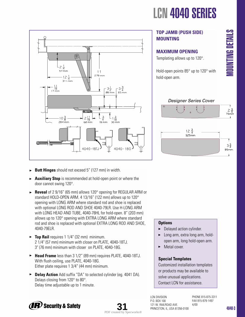
4040-3
PHONE 815-875-3311FAX 815-879-14974/00
LCN DIVISIONP.O. BOX 100121 W. RAILROAD AVE.PRINCETON, IL, USA 61356-0100
LCN 4040 SERIES
MOUN
TING D
ETAILSTOP JAMB (PUSH SIDE)
MOUNTING
MAXIMUM OPENINGTemplating allows up to 120°.
Hold-open points 85° up to 120° withhold-open arm.
Butt Hinges should not exceed 5” (127 mm) in width.
Auxiliary Stop is recommended at hold-open point or where the door cannot swing 120°.
Reveal of 2 9/16” (65 mm) allows 120° opening for REGULAR ARM orstandard HOLD-OPEN ARM. 4 13/16” (122 mm) allows up to 120°opening with LONG ARM where standard rod and shoe is replaced with optional LONG ROD AND SHOE 4040-79LR. Use H-LONG ARM with LONG HEAD AND TUBE, 4040-78HL for hold-open. 8” (203 mm) allows up to 120° opening with EXTRA LONG ARM where standard rod and shoe is replaced with optional EXTRA LONG ROD AND SHOE, 4040-79ELR.
Top Rail requires 1 1/4" (32 mm) minimum.2 1/4" (57 mm) minimum with closer on PLATE, 4040-18TJ.3" (76 mm) minimum with closer on PLATE, 4040-18G.
Head Frame less than 3 1/2” (89 mm) requires PLATE, 4040-18TJ. With flush ceiling, use PLATE, 4040-18G. Either plate requires 1 3/4” (44 mm) minimum.
Delay Action Add suffix “DA” to selected cylinder (eg. 4041 DA).Delays closing from 120° to 80°. Delay time adjustable up to 1 minute.
OptionsDelayed action cylinder.Long arm, extra long arm, hold-open arm, long hold-open arm.Metal cover.
Special Templates Customized installation templatesor products may be available tosolve unusual applications.Contact LCN for assistance.
31
Designer Series Cover
PDF created by Specworks®
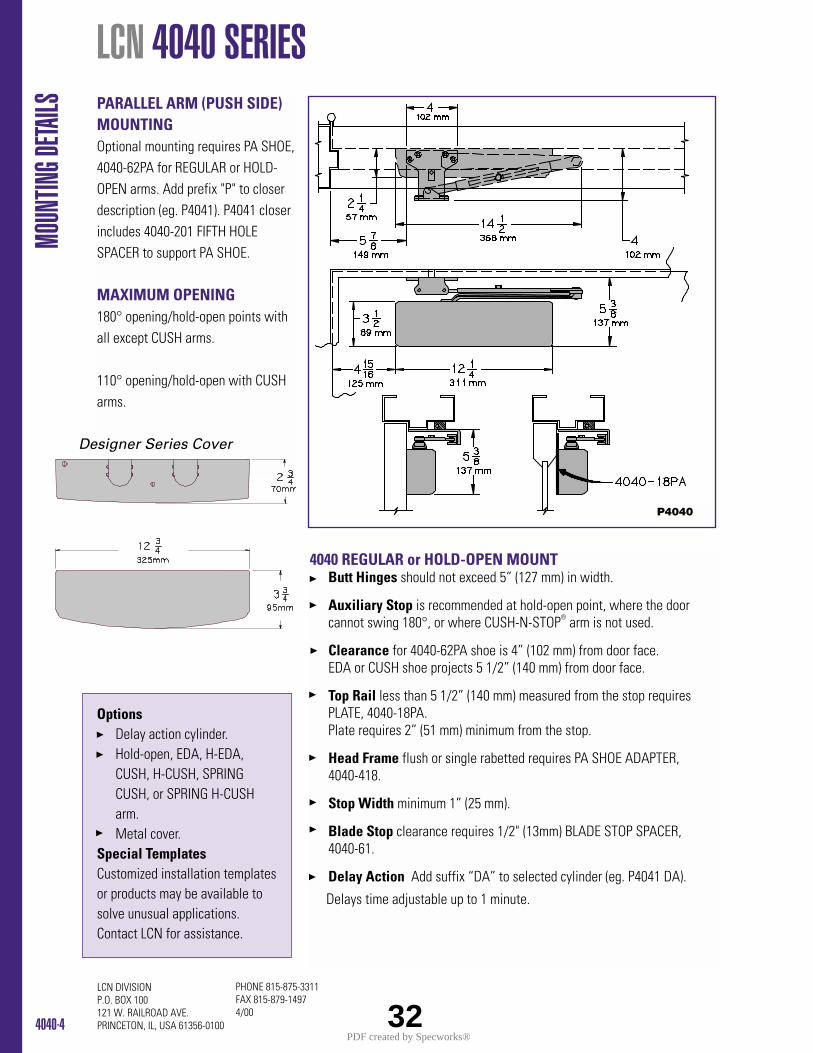
4040-4
PHONE 815-875-3311FAX 815-879-14974/00
LCN DIVISIONP.O. BOX 100121 W. RAILROAD AVE.PRINCETON, IL, USA 61356-0100
LCN 4040 SERIES MO
UNTIN
G DETA
ILS PARALLEL ARM (PUSH SIDE)MOUNTINGOptional mounting requires PA SHOE,4040-62PA for REGULAR or HOLD-OPEN arms. Add prefix "P" to closerdescription (eg. P4041). P4041 closerincludes 4040-201 FIFTH HOLESPACER to support PA SHOE.
MAXIMUM OPENING180° opening/hold-open points with all except CUSH arms.
110° opening/hold-open with CUSH arms.
4040 REGULAR or HOLD-OPEN MOUNTButt Hinges should not exceed 5” (127 mm) in width.
Auxiliary Stop is recommended at hold-open point, where the door cannot swing 180°, or where CUSH-N-STOP® arm is not used.
Clearance for 4040-62PA shoe is 4” (102 mm) from door face.EDA or CUSH shoe projects 5 1/2” (140 mm) from door face.
Top Rail less than 5 1/2” (140 mm) measured from the stop requires PLATE, 4040-18PA. Plate requires 2” (51 mm) minimum from the stop.
Head Frame flush or single rabetted requires PA SHOE ADAPTER, 4040-418.
Stop Width minimum 1” (25 mm).
Blade Stop clearance requires 1/2" (13mm) BLADE STOP SPACER, 4040-61.
Delay Action Add suffix “DA” to selected cylinder (eg. P4041 DA).
Delays time adjustable up to 1 minute.
OptionsDelay action cylinder.Hold-open, EDA, H-EDA, CUSH, H-CUSH, SPRING CUSH, or SPRING H-CUSHarm.Metal cover.
Special Templates Customized installation templatesor products may be available tosolve unusual applications.Contact LCN for assistance.
P4040
32
Designer Series Cover
PDF created by Specworks®
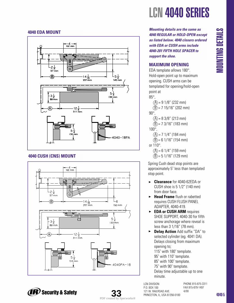
4040-5
PHONE 815-875-3311FAX 815-879-14974/00
LCN DIVISIONP.O. BOX 100121 W. RAILROAD AVE.PRINCETON, IL, USA 61356-0100
LCN 4040 SERIES
MOUN
TING D
ETAILS
Clearance for 4040-62EDA or CUSH shoe is 5 1/2” (140 mm) from door face.Head Frame flush or rabetted requires CUSH FLUSH PANEL ADAPTER, 4040-419.EDA or CUSH ARM requires SHOE SUPPORT, 4040-30 for fifth screw anchorage where reveal is less than 3 1/16” (78 mm).Delay Action Add suffix “DA” to selected cylinder (eg. 4041 DA). Delays closing from maximum opening to;115˚ with 180˚ template.95˚ with 110˚ template.85˚ with 100˚ template.75˚ with 90˚ template.Delay time adjustable up to oneminute.
4040 EDA MOUNT
4040 CUSH (CNS) MOUNT
MAXIMUM OPENINGEDA template allows 180°.Hold-open point up to maximumopening. CUSH arms can betemplated for opening/hold-openpoint at 85°,
A = 9 1/8” (232 mm)B = 7 15/16” (202 mm)
90°,A = 8 3/8” (213 mm)B = 7 3/16” (183 mm)
100°, A = 7 1/4” (184 mm)B = 6 1/16” (154 mm)
or 110°.A = 6 1/4” (159 mm)B = 5 1/16” (129 mm)
Mounting details are the same as4040 REGULAR or HOLD-OPEN exceptas listed below. 4040 closers orderedwith EDA or CUSH arms include 4040-201 FIFTH HOLE SPACER tosupport the shoe.
33
Spring Cush dead stop points areapproximately 5˚ less than templatedstop point.
PDF created by Specworks®
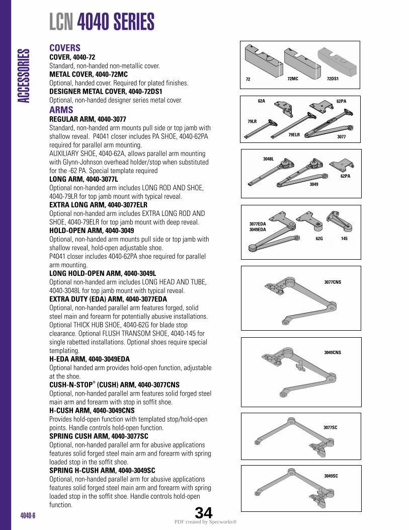
4040-6
LCN 4040 SERIES AC
CESS
ORIES
COVERSCOVER, 4040-72Standard, non-handed non-metallic cover.METAL COVER, 4040-72MCOptional, handed cover. Required for plated finishes.DESIGNER METAL COVER, 4040-72DS1Optional, non-handed designer series metal cover.ARMSREGULAR ARM, 4040-3077Standard, non-handed arm mounts pull side or top jamb withshallow reveal. P4041 closer includes PA SHOE, 4040-62PArequired for parallel arm mounting. AUXILIARY SHOE, 4040-62A, allows parallel arm mountingwith Glynn-Johnson overhead holder/stop when substitutedfor the -62 PA. Special template requiredLONG ARM, 4040-3077L Optional non-handed arm includes LONG ROD AND SHOE,4040-79LR for top jamb mount with typical reveal.EXTRA LONG ARM, 4040-3077ELROptional non-handed arm includes EXTRA LONG ROD ANDSHOE, 4040-79ELR for top jamb mount with deep reveal. HOLD-OPEN ARM, 4040-3049Optional, non-handed arm mounts pull side or top jamb withshallow reveal, hold-open adjustable shoe.P4041 closer includes 4040-62PA shoe required for parallelarm mounting.LONG HOLD-OPEN ARM, 4040-3049LOptional non-handed arm includes LONG HEAD AND TUBE,4040-3048L for top jamb mount with typical reveal.EXTRA DUTY (EDA) ARM, 4040-3077EDAOptional, non-handed parallel arm features forged, solidsteel main and forearm for potentially abusive installations.Optional THICK HUB SHOE, 4040-62G for blade stopclearance. Optional FLUSH TRANSOM SHOE, 4040-145 forsingle rabetted installations. Optional shoes require specialtemplating.H-EDA ARM, 4040-3049EDAOptional handed arm provides hold-open function, adjustableat the shoe.CUSH-N-STOP® (CUSH) ARM, 4040-3077CNSOptional, non-handed parallel arm features solid forged steelmain arm and forearm with stop in soffit shoe.H-CUSH ARM, 4040-3049CNSProvides hold-open function with templated stop/hold-openpoints. Handle controls hold-open function.SPRING CUSH ARM, 4040-3077SCOptional, non-handed parallel arm for abusive applicationsfeatures solid forged steel main arm and forearm with springloaded stop in the soffit shoe.SPRING H-CUSH ARM, 4040-3049SCOptional, non-handed parallel arm for abusive applicationsfeatures solid forged steel main arm and forearm with springloaded stop in the soffit shoe. Handle controls hold-openfunction.
72 72MC 72DS1
79LR
79ELR
62PA62A
3077
3048L
3049
62PA
3077EDA3049EDA
62G 145
3077CNS
3049CNS
3077SC
3049SC
34PDF created by Specworks®
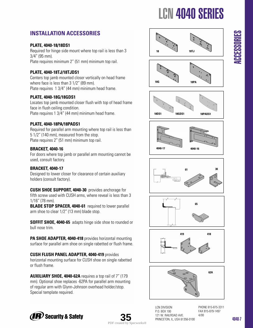
4040-7
PHONE 815-875-3311FAX 815-879-14974/00
LCN DIVISIONP.O. BOX 100121 W. RAILROAD AVE.PRINCETON, IL, USA 61356-0100
LCN 4040 SERIES
ACCE
SSOR
IESINSTALLATION ACCESSORIES
PLATE, 4040-18/18DS1Required for hinge side mount where top rail is less than 33/4” (95 mm).Plate requires minimum 2” (51 mm) minimum top rail.
PLATE, 4040-18TJ/18TJDS1Centers top jamb mounted closer vertically on head framewhere face is less than 3 1/2” (89 mm). Plate requires 1 3/4” (44 mm) minimum head frame.
PLATE, 4040-18G/18GDS1Locates top jamb mounted closer flush with top of head frameface in flush ceiling condition. Plate requires 1 3/4” (44 mm) minimum head frame.
PLATE, 4040-18PA/18PADS1Required for parallel arm mounting where top rail is less than5 1/2” (140 mm), measured from the stop. Plate requires 2” (51 mm) minimum top rail.
BRACKET, 4040-16For doors where top jamb or parallel arm mounting cannot beused, consult factory.
BRACKET, 4040-17Designed to lower closer for clearance of certain auxiliaryholders (consult factory).
CUSH SHOE SUPPORT, 4040-30 provides anchorage forfifth screw used with CUSH arms, where reveal is less than 31/16” (78 mm).BLADE STOP SPACER, 4040-61 required to lower parallelarm shoe to clear 1/2” (13 mm) blade stop.
SOFFIT SHOE, 4040-65 adapts hinge side shoe to rounded orbull nose trim.
PA SHOE ADAPTER, 4040-418 provides horizontal mountingsurface for parallel arm shoe on single rabetted or flush frame.
CUSH FLUSH PANEL ADAPTER, 4040-419 provideshorizontal mounting surface for CUSH shoe on single rabettedor flush frame.
AUXILIARY SHOE, 4040-62A requires a top rail of 7” (179mm). Optional shoe replaces -62PA for parallel arm mountingof regular arm with Glynn-Johnson overhead holder/stop.Special template required.
18G
18 18TJ
18PA
4040-17
419 418
65
61 30
4040-16
35
62A
18GDS118DS1 18PADS1
PDF created by Specworks®
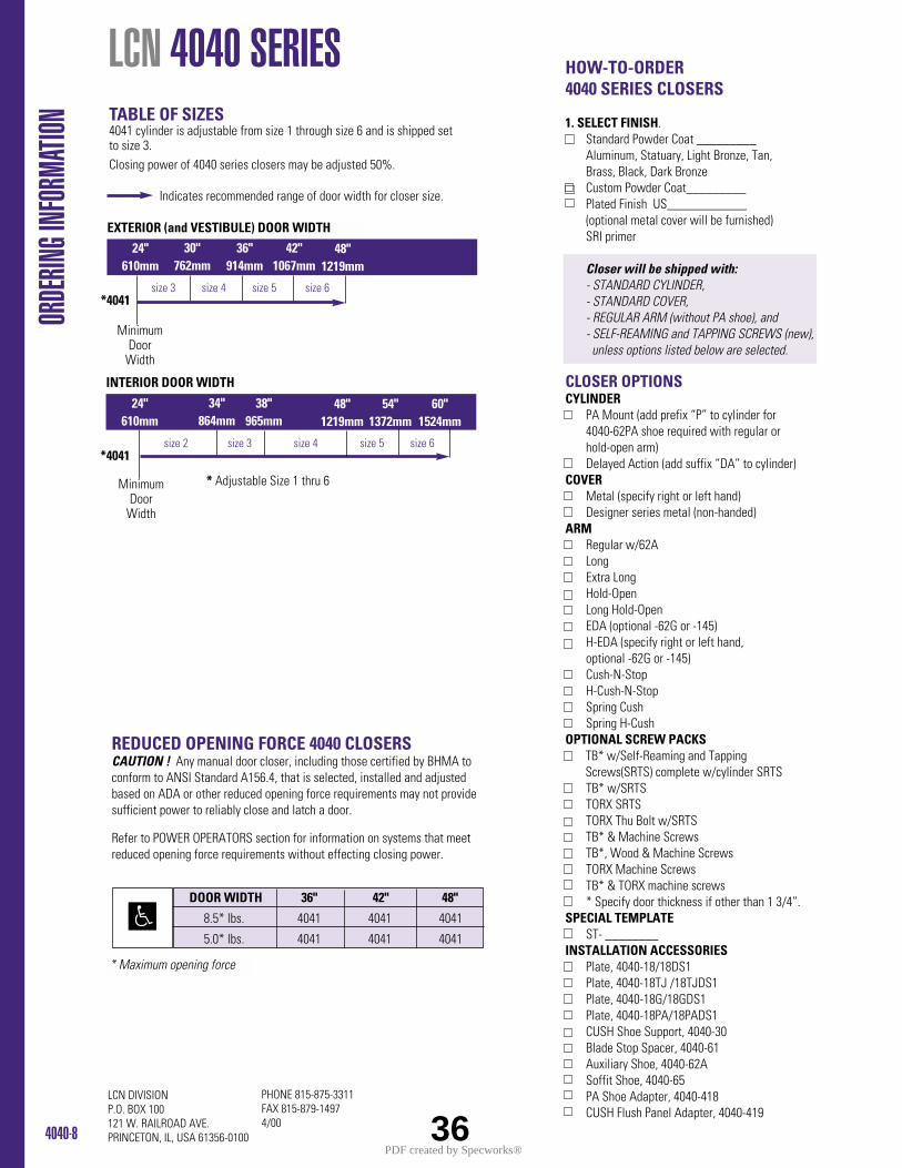
HOW-TO-ORDER4040 SERIES CLOSERS
1. SELECT FINISH.Standard Powder Coat _________Aluminum, Statuary, Light Bronze, Tan, Brass, Black, Dark BronzeCustom Powder Coat_________Plated Finish US____________ (optional metal cover will be furnished)SRI primer
Closer will be shipped with:- STANDARD CYLINDER, - STANDARD COVER, - REGULAR ARM (without PA shoe), and - SELF-REAMING and TAPPING SCREWS (new),unless options listed below are selected.
CLOSER OPTIONSCYLINDER
PA Mount (add prefix “P” to cylinder for 4040-62PA shoe required with regular or hold-open arm)Delayed Action (add suffix “DA” to cylinder)
COVERMetal (specify right or left hand)Designer series metal (non-handed)
ARMRegular w/62ALongExtra LongHold-OpenLong Hold-OpenEDA (optional -62G or -145)H-EDA (specify right or left hand, optional -62G or -145)Cush-N-StopH-Cush-N-StopSpring CushSpring H-Cush
OPTIONAL SCREW PACKSTB* w/Self-Reaming and Tapping Screws(SRTS) complete w/cylinder SRTSTB* w/SRTSTORX SRTSTORX Thu Bolt w/SRTSTB* & Machine ScrewsTB*, Wood & Machine ScrewsTORX Machine ScrewsTB* & TORX machine screws* Specify door thickness if other than 1 3/4”.
SPECIAL TEMPLATEST- ________
INSTALLATION ACCESSORIESPlate, 4040-18/18DS1Plate, 4040-18TJ /18TJDS1Plate, 4040-18G/18GDS1Plate, 4040-18PA/18PADS1CUSH Shoe Support, 4040-30Blade Stop Spacer, 4040-61Auxiliary Shoe, 4040-62ASoffit Shoe, 4040-65PA Shoe Adapter, 4040-418CUSH Flush Panel Adapter, 4040-419
4040-8
PHONE 815-875-3311FAX 815-879-14974/00
LCN DIVISIONP.O. BOX 100121 W. RAILROAD AVE.PRINCETON, IL, USA 61356-0100
Indicates recommended range of door width for closer size.
TABLE OF SIZES 4041 cylinder is adjustable from size 1 through size 6 and is shipped set to size 3.Closing power of 4040 series closers may be adjusted 50%.
REDUCED OPENING FORCE 4040 CLOSERSCAUTION ! Any manual door closer, including those certified by BHMA toconform to ANSI Standard A156.4, that is selected, installed and adjustedbased on ADA or other reduced opening force requirements may not providesufficient power to reliably close and latch a door.
Refer to POWER OPERATORS section for information on systems that meetreduced opening force requirements without effecting closing power.
* Maximum opening force
LCN 4040 SERIES OR
DERIN
G INF
ORMA
TION
size 3 size 4 size 5 size 6*4041
EXTERIOR (and VESTIBULE) DOOR WIDTH
24"610mm
30"762mm
36"914mm
42"1067mm
INTERIOR DOOR WIDTH
48"1219mm
24"610mm
34"864mm
38"965mm
48"1219mm
54"1372mm
60"1524mm
size 2 size 3 size 4 size 5 size 6*4041
* Adjustable Size 1 thru 6
DOOR WIDTH 36" 42" 48"
8.5* lbs. 4041 4041 4041
5.0* lbs. 4041 4041 4041
MinimumDoor
Width
MinimumDoor
Width
36PDF created by Specworks®
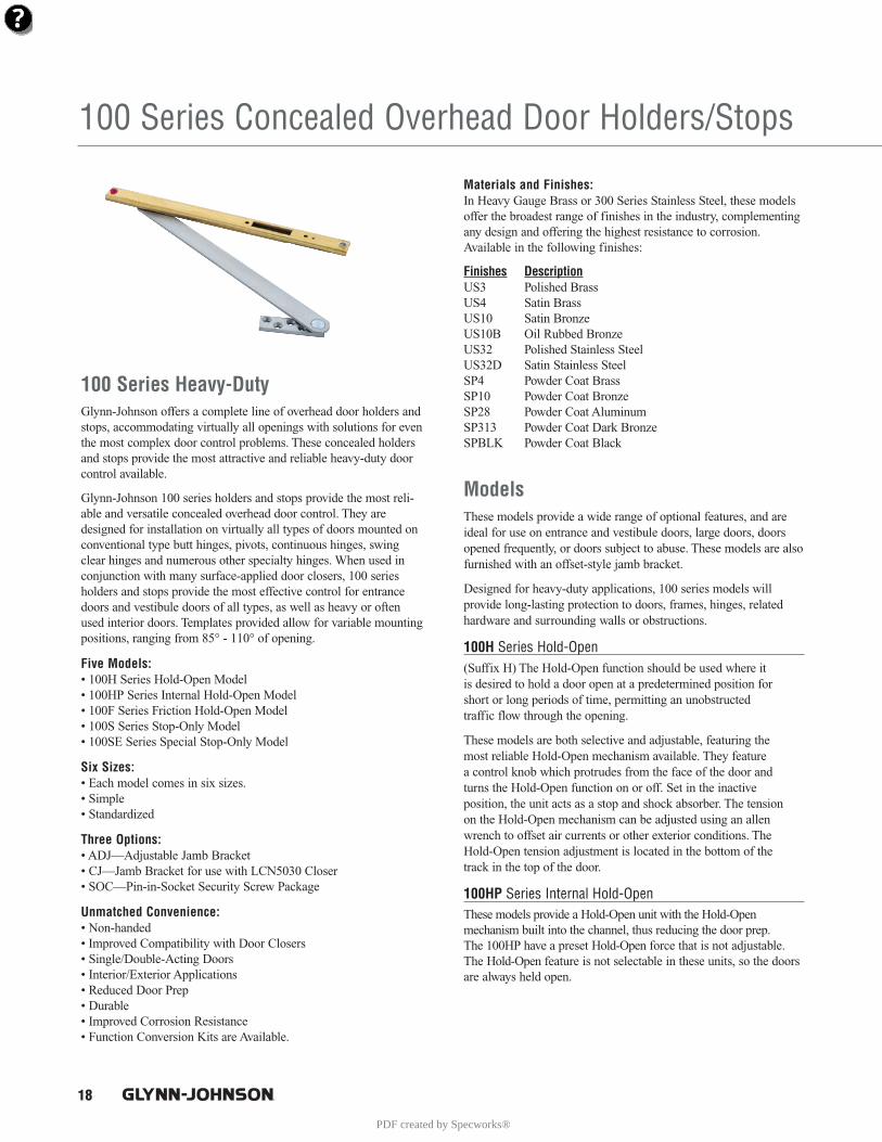
18
100 Series Concealed Overhead Door Holders/Stops
100 Series Heavy-DutyGlynn-Johnson offers a complete line of overhead door holders andstops, accommodating virtually all openings with solutions for eventhe most complex door control problems. These concealed holdersand stops provide the most attractive and reliable heavy-duty doorcontrol available.
Glynn-Johnson 100 series holders and stops provide the most reli-able and versatile concealed overhead door control. They aredesigned for installation on virtually all types of doors mounted onconventional type butt hinges, pivots, continuous hinges, swingclear hinges and numerous other specialty hinges. When used inconjunction with many surface-applied door closers, 100 seriesholders and stops provide the most effective control for entrancedoors and vestibule doors of all types, as well as heavy or oftenused interior doors. Templates provided allow for variable mountingpositions, ranging from 85° - 110° of opening.
Five Models: • 100H Series Hold-Open Model• 100HP Series Internal Hold-Open Model• 100F Series Friction Hold-Open Model• 100S Series Stop-Only Model• 100SE Series Special Stop-Only Model
Six Sizes:• Each model comes in six sizes.• Simple• Standardized
Three Options:• ADJ—Adjustable Jamb Bracket• CJ—Jamb Bracket for use with LCN5030 Closer• SOC—Pin-in-Socket Security Screw Package
Unmatched Convenience:• Non-handed• Improved Compatibility with Door Closers• Single/Double-Acting Doors• Interior/Exterior Applications• Reduced Door Prep• Durable• Improved Corrosion Resistance• Function Conversion Kits are Available.
Materials and Finishes:In Heavy Gauge Brass or 300 Series Stainless Steel, these modelsoffer the broadest range of finishes in the industry, complementingany design and offering the highest resistance to corrosion.Available in the following finishes:
Finishes DescriptionUS3 Polished BrassUS4 Satin BrassUS10 Satin BronzeUS10B Oil Rubbed BronzeUS32 Polished Stainless SteelUS32D Satin Stainless SteelSP4 Powder Coat BrassSP10 Powder Coat BronzeSP28 Powder Coat AluminumSP313 Powder Coat Dark BronzeSPBLK Powder Coat Black
ModelsThese models provide a wide range of optional features, and areideal for use on entrance and vestibule doors, large doors, doorsopened frequently, or doors subject to abuse. These models are alsofurnished with an offset-style jamb bracket.
Designed for heavy-duty applications, 100 series models will provide long-lasting protection to doors, frames, hinges, relatedhardware and surrounding walls or obstructions.
100H Series Hold-Open(Suffix H) The Hold-Open function should be used where it is desired to hold a door open at a predetermined position for short or long periods of time, permitting an unobstructed traffic flow through the opening.
These models are both selective and adjustable, featuring the most reliable Hold-Open mechanism available. They feature a control knob which protrudes from the face of the door and turns the Hold-Open function on or off. Set in the inactive position, the unit acts as a stop and shock absorber. The tension on the Hold-Open mechanism can be adjusted using an allenwrench to offset air currents or other exterior conditions. TheHold-Open tension adjustment is located in the bottom of the track in the top of the door.
100HP Series Internal Hold-OpenThese models provide a Hold-Open unit with the Hold-Open mechanism built into the channel, thus reducing the door prep. The 100HP have a preset Hold-Open force that is not adjustable. The Hold-Open feature is not selectable in these units, so the doorsare always held open.
PDF created by Specworks®
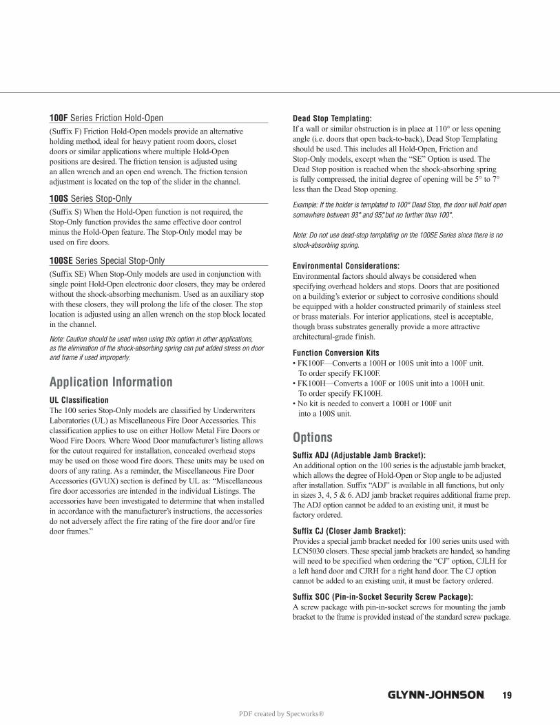
19
100F Series Friction Hold-Open (Suffix F) Friction Hold-Open models provide an alternative holding method, ideal for heavy patient room doors, closet doors or similar applications where multiple Hold-Open positions are desired. The friction tension is adjusted using an allen wrench and an open end wrench. The friction tension adjustment is located on the top of the slider in the channel.
100S Series Stop-Only(Suffix S) When the Hold-Open function is not required, the Stop-Only function provides the same effective door control minus the Hold-Open feature. The Stop-Only model may be used on fire doors.
100SE Series Special Stop-Only(Suffix SE) When Stop-Only models are used in conjunction withsingle point Hold-Open electronic door closers, they may be orderedwithout the shock-absorbing mechanism. Used as an auxiliary stopwith these closers, they will prolong the life of the closer. The stoplocation is adjusted using an allen wrench on the stop block locatedin the channel.
Note: Caution should be used when using this option in other applications, as the elimination of the shock-absorbing spring can put added stress on doorand frame if used improperly.
Application InformationUL ClassificationThe 100 series Stop-Only models are classified by UnderwritersLaboratories (UL) as Miscellaneous Fire Door Accessories. Thisclassification applies to use on either Hollow Metal Fire Doors orWood Fire Doors. Where Wood Door manufacturer’s listing allowsfor the cutout required for installation, concealed overhead stopsmay be used on those wood fire doors. These units may be used ondoors of any rating. As a reminder, the Miscellaneous Fire DoorAccessories (GVUX) section is defined by UL as: “Miscellaneousfire door accessories are intended in the individual Listings. Theaccessories have been investigated to determine that when installedin accordance with the manufacturer’s instructions, the accessoriesdo not adversely affect the fire rating of the fire door and/or firedoor frames.”
Dead Stop Templating: If a wall or similar obstruction is in place at 110° or less openingangle (i.e. doors that open back-to-back), Dead Stop Templatingshould be used. This includes all Hold-Open, Friction and Stop-Only models, except when the “SE” Option is used. The Dead Stop position is reached when the shock-absorbing spring is fully compressed, the initial degree of opening will be 5° to 7°less than the Dead Stop opening.
Example: If the holder is templated to 100° Dead Stop, the door will hold opensomewhere between 93° and 95°, but no further than 100°.
Note: Do not use dead-stop templating on the 100SE Series since there is noshock-absorbing spring.
Environmental Considerations:Environmental factors should always be considered when specifying overhead holders and stops. Doors that are positioned on a building’s exterior or subject to corrosive conditions should be equipped with a holder constructed primarily of stainless steel or brass materials. For interior applications, steel is acceptable,though brass substrates generally provide a more attractive architectural-grade finish.
Function Conversion Kits• FK100F—Converts a 100H or 100S unit into a 100F unit.
To order specify FK100F.• FK100H—Converts a 100F or 100S unit into a 100H unit.
To order specify FK100H.• No kit is needed to convert a 100H or 100F unit
into a 100S unit.
OptionsSuffix ADJ (Adjustable Jamb Bracket):An additional option on the 100 series is the adjustable jamb bracket,which allows the degree of Hold-Open or Stop angle to be adjustedafter installation. Suffix “ADJ” is available in all functions, but onlyin sizes 3, 4, 5 & 6. ADJ jamb bracket requires additional frame prep.The ADJ option cannot be added to an existing unit, it must be factory ordered.
Suffix CJ (Closer Jamb Bracket):Provides a special jamb bracket needed for 100 series units used withLCN5030 closers. These special jamb brackets are handed, so handingwill need to be specified when ordering the “CJ” option, CJLH fora left hand door and CJRH for a right hand door. The CJ optioncannot be added to an existing unit, it must be factory ordered.
Suffix SOC (Pin-in-Socket Security Screw Package):A screw package with pin-in-socket screws for mounting the jambbracket to the frame is provided instead of the standard screw package.
PDF created by Specworks®
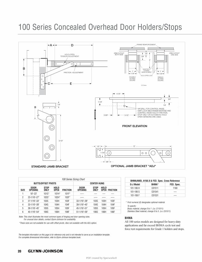
20
100 Series Concealed Overhead Door Holders/Stops
The template information on this page is for reference only and is not intended to serve as an installation template. For complete dimensional information, refer to Glynn-Johnson template book.
1-1/4"1"
1/4"
1-1/4"1"
2"
3/4"
3/8"
4-1/4"
1-1/4"
2-3/8" 5-1/2"
1/4"
3/4"
1"
1/4"
3-1/2"
1-1/4"
1/2"
3/8"
12"
BUTTS/OFFSET PIVOTS CENTER HUNG
DOOR STOP HOLD DOOR STOP HOLDSIZE OPENING ONLY OPEN FRICTION OPENING ONLY OPEN FRICTION
1 18"–23" 101S* 101H* 101F* ----- ---- ---- ----2 23-1/16"–27" 102S* 102H* 102F* ----- ----- ----- -----3 27-1/16"–33" 103S 103H 103F 33-1/16"–39" 103S 103H 103F 4 33-1/16"–39" 104S 104H 104F 39-1/16"–45" 104S 104H 104F5 39-1/16"–45" 105S 105H 105F 45-1/16"–51" 105S 105H 105F6 45-1/16"–54" 106S 106H 106F 51-1/16"–59" 106S 106H 106F
100 Series Sizing Chart
* First numeral (0) designates optional material.
To specify: Brass material, change 0 to 1 (i.e. C11511)Stainless Steel material, change 0 to 5 (i.e. C51511)
Note: This chart illustrates the most common types of hinging and door opening sizes. For unusual door details, contact Glynn-Johnson for availability.
*These sizes are not available for use with offset pivots. Also not available with the ADJ option.
BHMAAll 100 series models are designed for heavy-dutyapplications and far exceed BHMA cycle test andforce test requirements for Grade 1 holders and stops.
BHMA/ANSI, A156.8 & FED. Spec. Cross ReferenceG-J Model BHMA* FED. Spec.101-106 H C01511 1160101-106 S C01541 ----101-106 F C01531 ----
PDF created by Specworks®
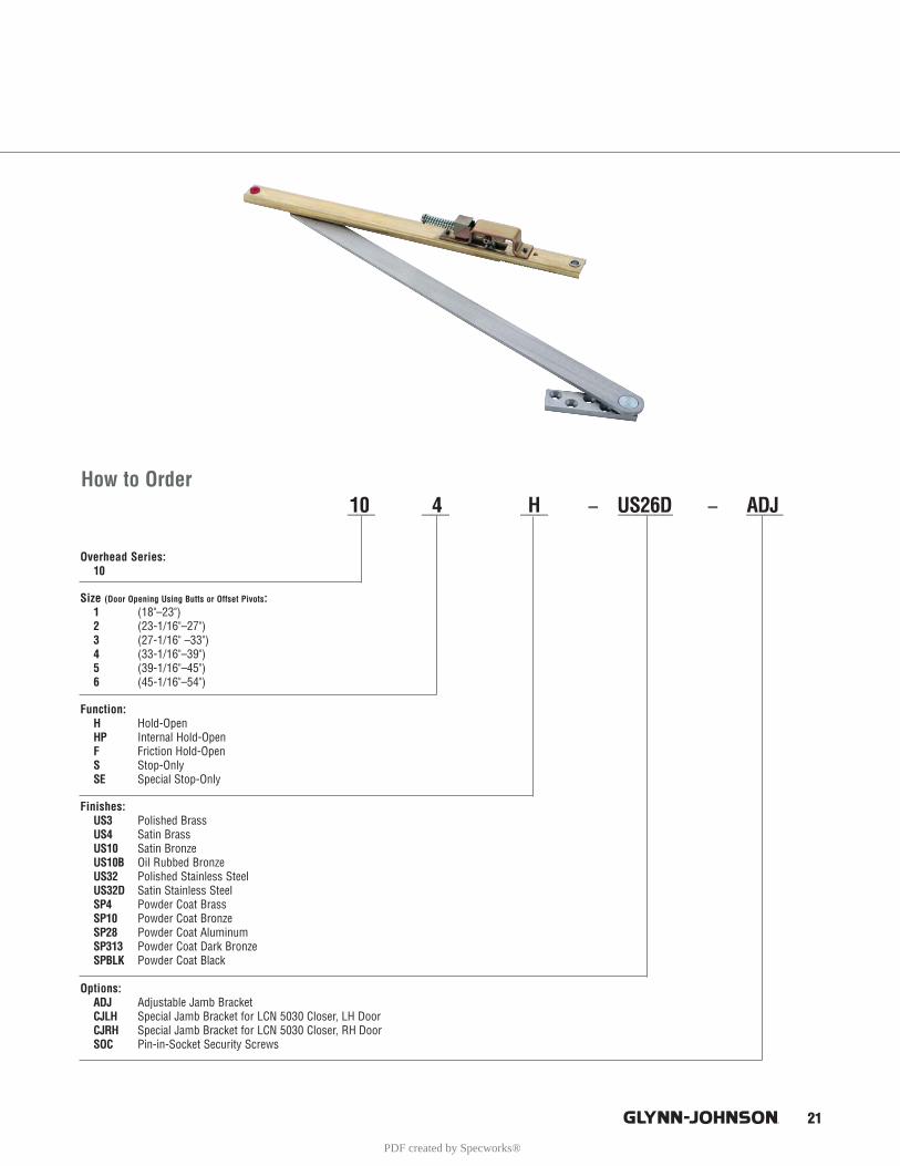
21
How to Order
Overhead Series:10
Size (Door Opening Using Butts or Offset Pivots:1 (18"–23")2 (23-1/16"–27")3 (27-1/16" –33")4 (33-1/16"–39")5 (39-1/16"–45")6 (45-1/16"–54")
Function:H Hold-OpenHP Internal Hold-OpenF Friction Hold-OpenS Stop-OnlySE Special Stop-Only
Finishes:US3 Polished BrassUS4 Satin BrassUS10 Satin BronzeUS10B Oil Rubbed BronzeUS32 Polished Stainless SteelUS32D Satin Stainless SteelSP4 Powder Coat BrassSP10 Powder Coat BronzeSP28 Powder Coat AluminumSP313 Powder Coat Dark BronzeSPBLK Powder Coat Black
Options:ADJ Adjustable Jamb BracketCJLH Special Jamb Bracket for LCN 5030 Closer, LH DoorCJRH Special Jamb Bracket for LCN 5030 Closer, RH DoorSOC Pin-in-Socket Security Screws
___ ___ ___ – ______ – ____10 4 H US26D ADJ
PDF created by Specworks®
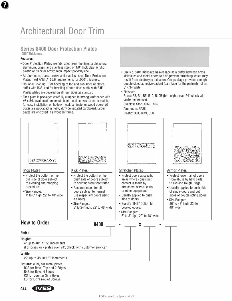
C14
Architectural Door Trim
Mop Plates• Protect the bottom of the
pull side of door subject to cleaning and mopping procedures.
• Size Ranges:4" to 6" high, 22" to 48" wide
Kick Plates• Protect the bottom of the
push side of doors subject to scuffing from foot traffic.
• Recommended for all doors subject to normaluse (especially doors using a closer).
• Size Ranges:8" to 24" high, 22" to 48" wide
Stretcher Plates• Protect doors at specific
areas where consistent contact is made by stretchers, service carts or other equipment.
• Usually applied to push side of doors.
• Specify “B4E” Option forbeveled edges.
• Size Ranges:6" to 8" high, 22" to 48" wide
Armor Plates• Protect lower half of doors
from abuse by hard carts,trucks and rough usage.
• Usually applied to push sideof single doors and bothsides of double acting doors.
• Size Ranges:26" to 48" high, 22" to 48" wide
Series 8400 Door Protection Plates.050" ThicknessFeatures:• Door Protection Plates are fabricated from the finest architectural
aluminum, brass, and stainless steel, or 1/8" thick clear acrylicplastic or black or brown high impact polyethylene.
• All aluminum, brass, bronze and stainless steel Door ProtectionPlates meet ANSI A156.6 requirements for .050" thickness.
• Optional Beveling—For beveling of top and two sides of plates suffix with B3E, and for beveling of four sides suffix with B4E. Plastic plates are beveled on all four sides as standard.
• Each plate is packaged carefully wrapped in strong kraft paper with#6 x 5/8" oval head, undercut sheet metal screws plated to match,for easy installation on hollow metal, laminate, or wood doors. Allplates are packaged in heavy duty corrugated cardboard; largerplates are enclosed in a wooden frame.
• Use No. 8401 Kickplate Gasket Tape as a buffer between brasskickplates and metal doors to help prevent tarnishing which mayresult from electrolytic oxidation. One package provides enoughdouble-sided adhesive-backed foam tape for the perimeter of an 8" x 34" plate.
• Finishes:Brass: B3, B4, B5, B10, B10B (for heights over 24", check withcustomer serivce)Stainless Steel: S32D, S32Aluminum: PA28Plastic: BLK, BRN, CLR
How to Order 8400 ____ - _____ x _____ - _____Finish
Height: 4" up to 48" in 1/2" increments (For brass kick plates over 24", check with customer service.)
Width:22" up to 48" in 1/2" increments
Options: (Only for metal plates)B3E for Bevel Top and 2 EdgesB4E for Bevel 4 EdgesCS for Counter Sink HolesES for Extra row of Screws
PDF created by Specworks®
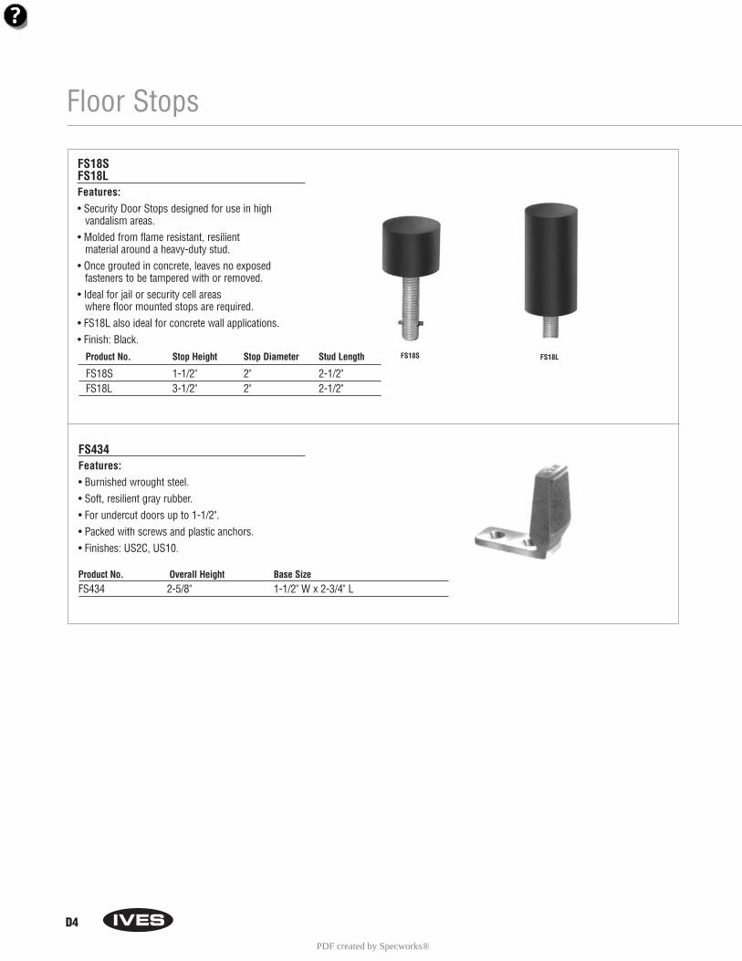
D4
Floor Stops
FS18SFS18LFeatures:• Security Door Stops designed for use in high
vandalism areas.• Molded from flame resistant, resilient
material around a heavy-duty stud.• Once grouted in concrete, leaves no exposed
fasteners to be tampered with or removed.• Ideal for jail or security cell areas
where floor mounted stops are required.• FS18L also ideal for concrete wall applications.• Finish: Black.
FS434Features:• Burnished wrought steel.• Soft, resilient gray rubber.• For undercut doors up to 1-1/2".• Packed with screws and plastic anchors.• Finishes: US2C, US10.
FS18S FS18L
Product No. Overall Height Base SizeFS434 2-5/8" 1-1/2" W x 2-3/4" L
Product No. Stop Height Stop Diameter Stud Length
FS18S 1-1/2" 2" 2-1/2"FS18L 3-1/2" 2" 2-1/2"
PDF created by Specworks®
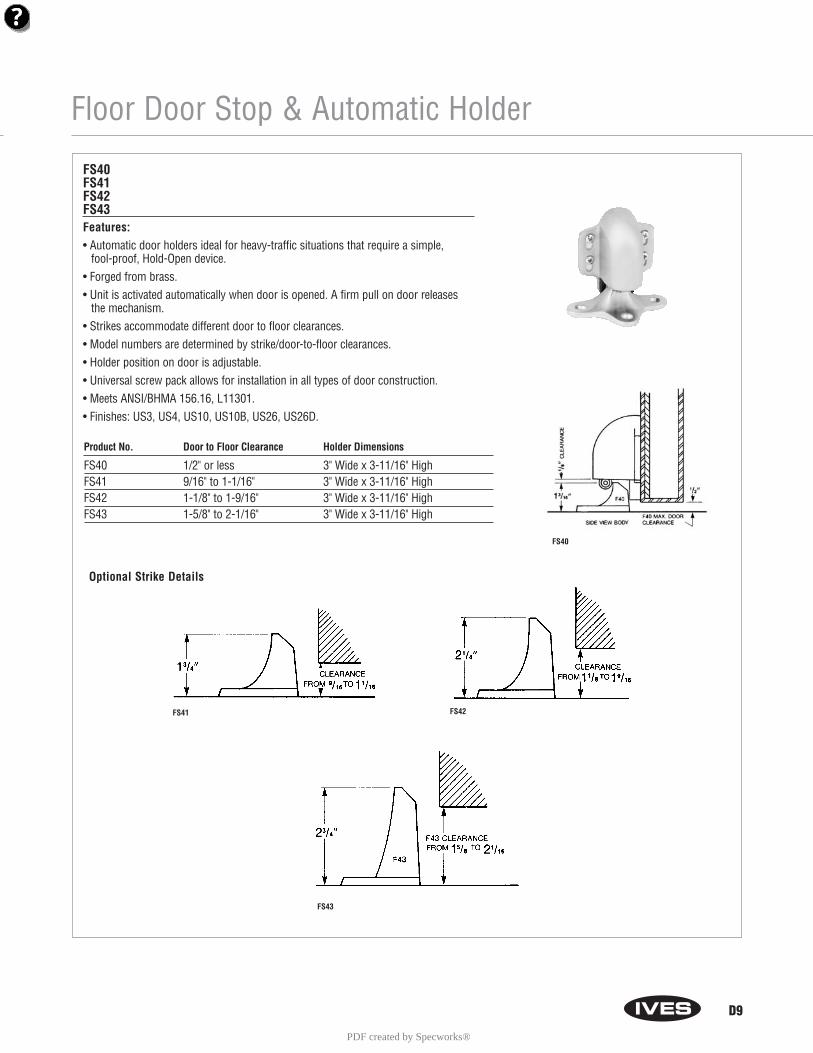
Floor Door Stop & Automatic Holder
D9
FS40FS41FS42FS43Features:• Automatic door holders ideal for heavy-traffic situations that require a simple,
fool-proof, Hold-Open device.• Forged from brass.• Unit is activated automatically when door is opened. A firm pull on door releases
the mechanism.• Strikes accommodate different door to floor clearances.• Model numbers are determined by strike/door-to-floor clearances.• Holder position on door is adjustable.• Universal screw pack allows for installation in all types of door construction.• Meets ANSI/BHMA 156.16, L11301.• Finishes: US3, US4, US10, US10B, US26, US26D.
Product No. Door to Floor Clearance Holder Dimensions
FS40 1/2" or less 3" Wide x 3-11/16" HighFS41 9/16" to 1-1/16" 3" Wide x 3-11/16" HighFS42 1-1/8" to 1-9/16" 3" Wide x 3-11/16" HighFS43 1-5/8" to 2-1/16" 3" Wide x 3-11/16" High
Optional Strike Details
FS41 FS42
FS40
FS43
PDF created by Specworks®
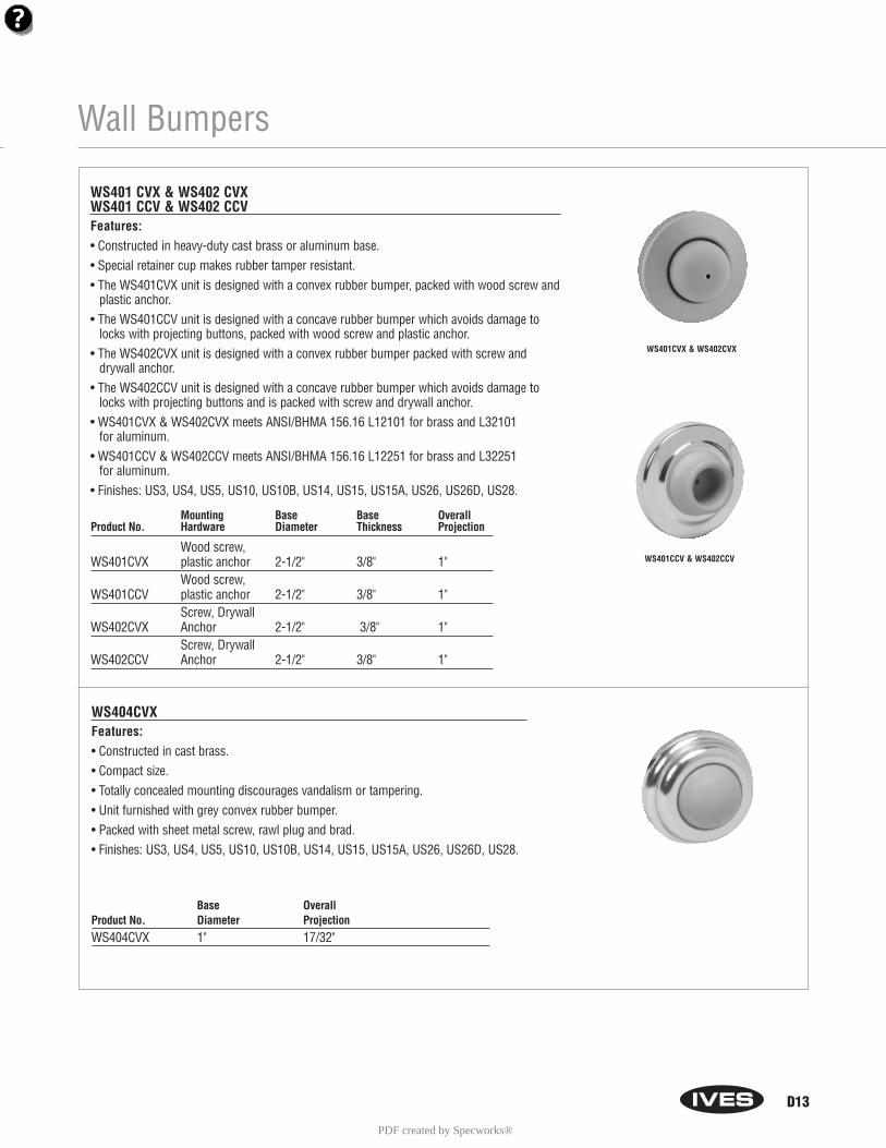
Wall Bumpers
D13
WS401 CVX & WS402 CVXWS401 CCV & WS402 CCVFeatures:• Constructed in heavy-duty cast brass or aluminum base.• Special retainer cup makes rubber tamper resistant.• The WS401CVX unit is designed with a convex rubber bumper, packed with wood screw and
plastic anchor.• The WS401CCV unit is designed with a concave rubber bumper which avoids damage to
locks with projecting buttons, packed with wood screw and plastic anchor.• The WS402CVX unit is designed with a convex rubber bumper packed with screw and
drywall anchor.• The WS402CCV unit is designed with a concave rubber bumper which avoids damage to
locks with projecting buttons and is packed with screw and drywall anchor.• WS401CVX & WS402CVX meets ANSI/BHMA 156.16 L12101 for brass and L32101
for aluminum.• WS401CCV & WS402CCV meets ANSI/BHMA 156.16 L12251 for brass and L32251
for aluminum.• Finishes: US3, US4, US5, US10, US10B, US14, US15, US15A, US26, US26D, US28.
WS404CVXFeatures:• Constructed in cast brass.• Compact size.• Totally concealed mounting discourages vandalism or tampering.• Unit furnished with grey convex rubber bumper.• Packed with sheet metal screw, rawl plug and brad.• Finishes: US3, US4, US5, US10, US10B, US14, US15, US15A, US26, US26D, US28.
Base OverallProduct No. Diameter ProjectionWS404CVX 1" 17/32"
Mounting Base Base OverallProduct No. Hardware Diameter Thickness Projection
Wood screw,WS401CVX plastic anchor 2-1/2" 3/8" 1"
Wood screw,WS401CCV plastic anchor 2-1/2" 3/8" 1"
Screw, DrywallWS402CVX Anchor 2-1/2" 3/8" 1"
Screw, DrywallWS402CCV Anchor 2-1/2" 3/8" 1"
WS401CVX & WS402CVX
WS401CCV & WS402CCV
PDF created by Specworks®
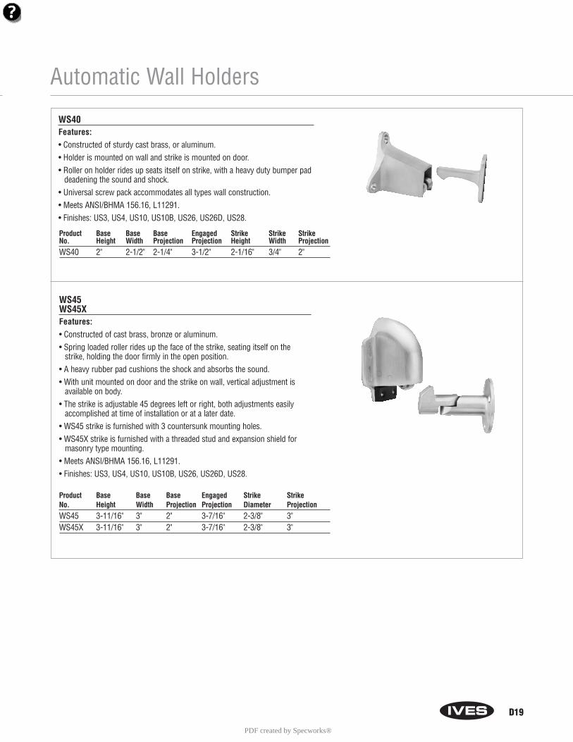
Automatic Wall Holders
WS40Features:• Constructed of sturdy cast brass, or aluminum.• Holder is mounted on wall and strike is mounted on door.• Roller on holder rides up seats itself on strike, with a heavy duty bumper pad
deadening the sound and shock.• Universal screw pack accommodates all types wall construction.• Meets ANSI/BHMA 156.16, L11291.• Finishes: US3, US4, US10, US10B, US26, US26D, US28.
WS45WS45XFeatures:• Constructed of cast brass, bronze or aluminum.• Spring loaded roller rides up the face of the strike, seating itself on the
strike, holding the door firmly in the open position.• A heavy rubber pad cushions the shock and absorbs the sound.• With unit mounted on door and the strike on wall, vertical adjustment is
available on body.• The strike is adjustable 45 degrees left or right, both adjustments easily
accomplished at time of installation or at a later date.• WS45 strike is furnished with 3 countersunk mounting holes.• WS45X strike is furnished with a threaded stud and expansion shield for
masonry type mounting.• Meets ANSI/BHMA 156.16, L11291.• Finishes: US3, US4, US10, US10B, US26, US26D, US28.
Product Base Base Base Engaged Strike Strike StrikeNo. Height Width Projection Projection Height Width ProjectionWS40 2" 2-1/2" 2-1/4" 3-1/2" 2-1/16" 3/4" 2"
Product Base Base Base Engaged Strike StrikeNo. Height Width Projection Projection Diameter ProjectionWS45 3-11/16" 3" 2" 3-7/16" 2-3/8" 3"WS45X 3-11/16" 3" 2" 3-7/16" 2-3/8" 3"
D19
PDF created by Specworks®
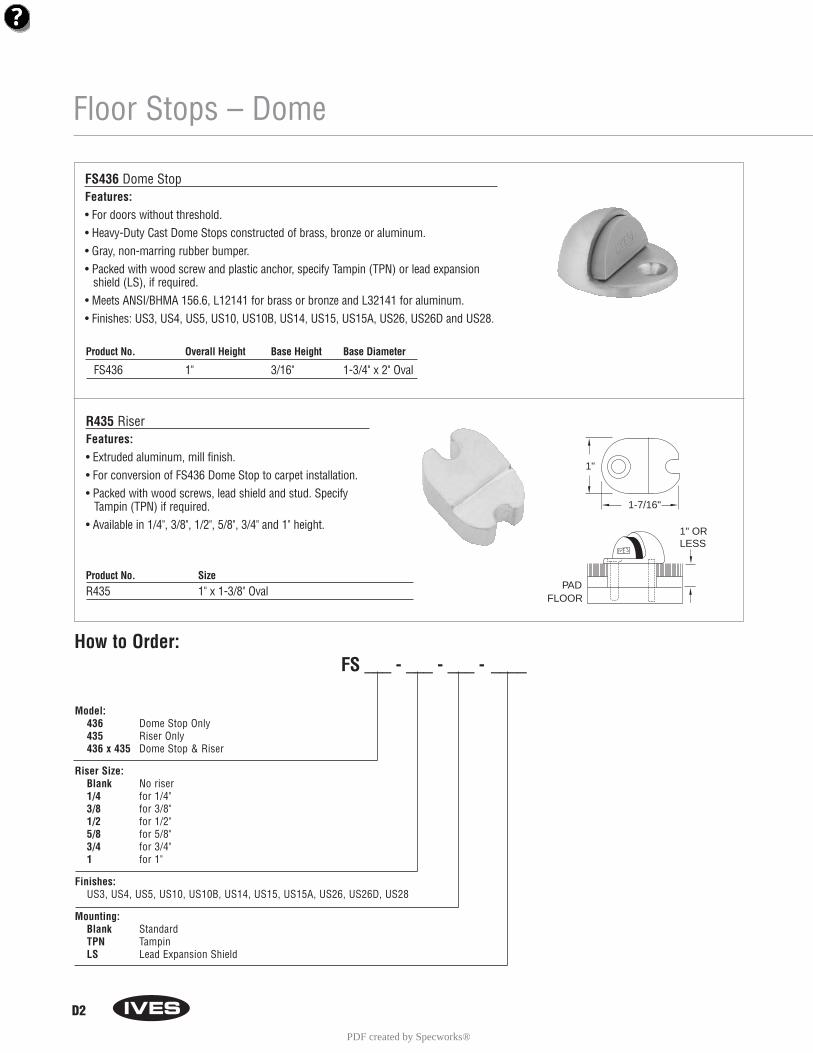
Floor Stops – Dome
D2
FS436 Dome StopFeatures:• For doors without threshold.• Heavy-Duty Cast Dome Stops constructed of brass, bronze or aluminum.• Gray, non-marring rubber bumper.• Packed with wood screw and plastic anchor, specify Tampin (TPN) or lead expansion
shield (LS), if required.• Meets ANSI/BHMA 156.6, L12141 for brass or bronze and L32141 for aluminum.• Finishes: US3, US4, US5, US10, US10B, US14, US15, US15A, US26, US26D and US28.
R435 RiserFeatures:• Extruded aluminum, mill finish.• For conversion of FS436 Dome Stop to carpet installation.• Packed with wood screws, lead shield and stud. Specify
Tampin (TPN) if required.• Available in 1/4", 3/8", 1/2", 5/8", 3/4" and 1" height.
Product No. SizeR435 1" x 1-3/8" Oval
Product No. Overall Height Base Height Base Diameter
FS436 1" 3/16" 1-3/4" x 2" Oval
PADFLOOR
1" ORLESS
1"
1-7/16"
Model:436 Dome Stop Only435 Riser Only436 x 435 Dome Stop & Riser
Riser Size:Blank No riser1/4 for 1/4"3/8 for 3/8"1/2 for 1/2"5/8 for 5/8"3/4 for 3/4"1 for 1"
Finishes:US3, US4, US5, US10, US10B, US14, US15, US15A, US26, US26D, US28
Mounting:Blank StandardTPN TampinLS Lead Expansion Shield
How to Order:FS ___ - ___ - ___ - ____
PDF created by Specworks®
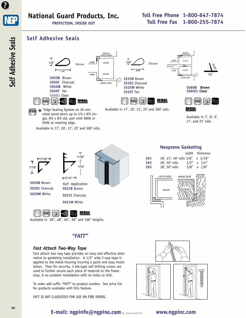
Toll Free Phone 1-800-647-7874Toll Free Fax 1-800-255-7874
E-mail: [email protected] www.ngpinc.com50
National Guard Products, Inc.PROTECTION, INSIDE OUT
Available in 36”, 48”, 84”, 96” and 108” lengths.
7/16"
7/16"
Self Adhesive Seals
5020B Brown
5020C Charcoal
5020W White
Available in 17’, 20’, 21’, 25’ and 300’ rolls.
1/4"
3/8"
2525B Brown2525C Charcoal2525W White2525T Tan
1/2"
1/4"
5050B Brown5050C Charcoal5050W White5050T Tan5050CL Clear
HEAD &LATCH SIDE
DOORJAMB
HINGE SIDE
DOORJAMB
5021B Brown
5021C Charcoal
5021W White
11/32"
7/16"
7/16"
Available in 17’, 20’, 21’, 25’ and 300’ rolls.
DOOR DOOR
LATCH SIDE HINGE SIDE
Neoprene Gasketingwidth thickness
361 18’, 21’, 50’ rolls 3/8” x 3/16”362 18’, 50’ rolls 1/2” x 1/4”363 18’, 50’ rolls 3/8” x 1/8”
Self
Adhe
sive
Seals
Kerf Application
SiliconeSilicone
10C S
10C S
ESS **Edge Sealing System on 20 minrated wood doors up to 4’0 x 8’0 sin-gle, 8’0 x 8’0 std. pair with 9800 or9500 at meeting edge.
10C S
“FATT”
Fast Attach Two-Way Tape Fast attach two way tape provides an easy and effective alter-native to gasketing installation. A 1/2” wide 2-way tape isapplied to the metal housing insuring a quick and easy instal-lation. Then for security, 3 tek-type self drilling screws areused to further secure each piece of material to the framestop. A no problem installation with no holes to drill.
To order add suffix “FATT” to product number. See price listfor products available with this feature.
FATT IS NOT CLASSIFIED FOR USE ON FIRE DOORS.
1/2"
5/16"
5060B Brown5060CL Clear
Available in 7’, 8’, 9’,17’, and 21’ rolls
10C S
HEAD &LATCH SIDE
DOORJAMB
HINGE SIDE
DOORJAMB
(optional astragal application)
PDF created by Specworks®
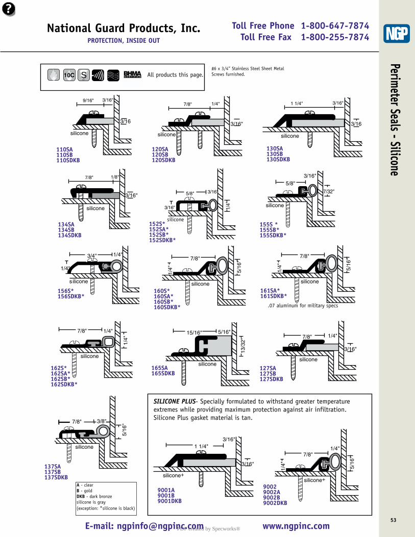
National Guard Products, Inc.PROTECTION, INSIDE OUT
E-mail: [email protected] www.ngpinc.com53
Toll Free Phone 1-800-647-7874Toll Free Fax 1-800-255-7874
9/16"
3/16
silicone
3/16"
110SA 110SB110SDKB
3/16"
silicone
7/8" 1/4"
120SA 120SB120SDKB
3/16"
silicone
1 1/4" 3/16"
130SA 130SB130SDKB
5/8"
3/16" 1/4"
vinyl
3/16"
152S* 152SA* 152SB*152SDKB*
5/8"
7/32"
silicone
3/16"
155S *155SB*155SDKB*
3/4"
1/4"
silicone
1/4"
156S* 156SDKB*
3/16"
silicone
7/8" 1/8"
134SA 134SB134SDKB
7/8"
5/16
"
1/4"
silicone160S*160SA* 160SB*160SDKB*
7/8"
5/16
"
1/4"
silicone
161SA* 161SDKB*
7/8"
1/4"
1/4"
silicone
162S*162SA* 162SB*162SDKB*
15/16"
13/3
2"
silicone
5/16"
165SA 165SDKB
7/8"
3/16"
silicone
1/4"
127SA 127SB127SDKB
5/16
"3/8"
silicone
7/8"
137SA 137SB137SDKB
1 1/4"
3/16"
silicone+
3/16"
9001A 9001B9001DKB
7/8"
5/16
"
1/4"
silicone+
1/4"
90029002A 9002B9002DKB
SILICONE PLUS- Specially formulated to withstand greater temperatureextremes while providing maximum protection against air infiltration.Silicone Plus gasket material is tan.
silicone
Perimeter Seals - Silicone
.07 aluminum for military specs
All products this page. 10C#6 x 3/4” Stainless Steel Sheet MetalScrews furnished.S
A - clear B - gold DKB - dark bronzesilicone is gray (exception: *silicone is black)
PDF created by Specworks®
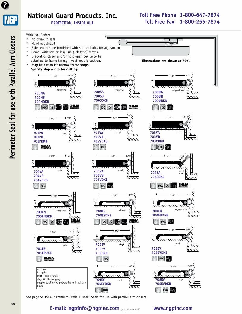
Toll Free Phone 1-800-647-7874Toll Free Fax 1-800-255-7874
E-mail: [email protected] www.ngpinc.com58
National Guard Products, Inc.PROTECTION, INSIDE OUT
Illustrations are shown at 70%.
With 700 Series:* No break in seal* Head not drilled* Side sections are furnished with slotted holes for adjustment * Comes with self drilling #8 (Tek type) screws.* Bracket or closer and/or hold open device to be
attached to frame through weatherstrip section.* May be cut to fit narrow frame stops.
Specify stop width for cutting.
neoprene
1 1/2"
1/4"
3/16"
pile
1 1/2"
1/4"
1/4"
700NA700NB 700NDKB
silicone
1 1/2"
1/4"
1/4"
polyurethane
1 1/2"
1/4"
3/16"
vinyl
1 1/2"
1/4"
1/8"
vinyl
1 1/2"
1/4"
3/16"
701PA701PB 701PDKB
702VA702VB 702VDKB
703VA703VB 703VDKB
700SA700SB 700SDKB
700UA700UB 700UDKB
vinyl
1 1/2"
1/4"
1/4"
vinyl
1 1/2"
1/4"
3/16"
704VA704VB 704VDKB
705VA705VB 705VDKB
1 1/2"3/8
"
nylonbrush706EA
706EDKB
neoprene
1 1/2"
1/4"
3/16"
silicone
1 1/2"
1/4"
1/4"
700EN700ENDKB
700ES 700ESDKB
polyurethane
1 1/2"
1/4"
3/16"
700EU 700EUDKB
pile
1 1/2"
1/4"
7/16"
701EP 701EPDKB
702EV 702EV702DKB
vinyl
1 1/2"
1/4"
3/16"
703EV 703EVDKB
vinyl
1 1/2"
1/4"
1/4"
vinyl
1 1/2"
1/4"
3/16"
704EV 704EVDKB
705EV 705EVDKB
Perim
eter
Seal
for u
se w
ith Pa
rallel
Arm
Clos
ers
See page 59 for our Premium Grade Allseal® Seals for use with parallel arm closers.
10C S 10C 10C
10C 10C
10C10C
10C 10C
10C 10C 10C S
10C S 10C 10C
S
S
A - clearB - gold DKB - dark bronzevinyl & pile are grayneoprene, silicone, polyurethane, brush areblack
PDF created by Specworks®
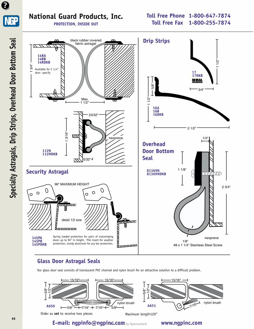
Toll Free Phone 1-800-647-7874Toll Free Fax 1-800-255-7874
E-mail: [email protected] www.ngpinc.com66
National Guard Products, Inc.PROTECTION, INSIDE OUT
1 1/2"
112N112N DkB
eoprene
black rubber covered fabric astragal
1 3/
4"
Max.
14RA14RB14RDKB
23/32"
1 3/
16"
neoprene
5/32"
112N112NDKB
detail 1/2 size
96" MAXIMUM HEIGHT
145PA145PB145PDKB
Spring loaded protection for pairs of outswingingdoors up to 96” in height. Pile insert for weatherprotection, sturdy aluminum for pry bar protection.
5/8"
nylon brush
15/16" 15/16"
5/8" 7/16" 7/16" 5/8"
1/2"
A650
5/8"
15/16"
7/16" nylon brush
1/2"
A651
Our glass door seal consists of translucent PVC channel and nylon brush for an attractive solution to a difficult problem.
Glass Door Astragal Seals
Order as set to receive two pieces Maximum length120”
Available for 2 1/4”door- specify
Spec
ialty
Astr
agals
, Drip
Strip
s, Ov
erhe
ad D
oor B
otto
m Se
al Drip Strips
2 1/2"
1 1/
2"5/
8"
3/4"
1 1/
2"
16A16B16DKB
1717DKB
neoprene
#8 x 1 1/4" Stainless Steel Screw
1/4"
1 1/8"
2 3/4"
1/8"
81369N81369NDKBSecurity Astragal
OverheadDoor BottomSeal
PDF created by Specworks®
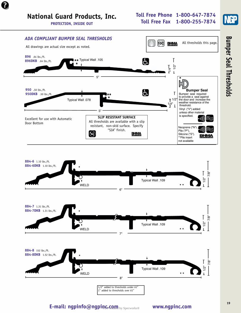
National Guard Products, Inc.PROTECTION, INSIDE OUT
E-mail: [email protected] www.ngpinc.com19
Bumper Seal ThresholdsToll Free Phone 1-800-647-7874
Toll Free Fax 1-800-255-7874
Typical Wall .105
5"
1/2"
1/4"
***
896 .64 lbs./ft.
896DKB .64 lbs./ft.
5"
1/2"Typical Wall .078 *1/4"
**950 .50 lbs./ft.
950DKB .50 lbs./ft.
ADA COMPLIANT BUMPER SEAL THRESHOLDS
SLIP RESISTANT SURFACEAll thresholds are available with a slipresistant, non-skid surface. Specify
“SIA” finish.
1/2"
7/8"
Typical Wall .109
WELD6"
*
* *
884-6 1.10 lbs./ft.
884-6DKB 1.10 lbs./ft.
1/2"
7/8"
Typical Wall .109
WELD7"
*
* *
884-7 1.31 lbs./ft.
884-7DKB 1.31 lbs./ft.
1/2"
7/8"
Typical Wall .109
WELD8"
*
* *
884-8 152 lbs./ft.
884-8DKB 1.52 lbs./ft.
1/2” added to thresholds under 61”1” added to thresholds over 61”
All drawings are actual size except as noted.
Excellent for use with AutomaticDoor Bottom
All thresholds this page. 10C
Bumper Seal
*
Bumper seal requiredto provide a seal againstthe door and increase theweather resistance of thethreshold.Vinyl ("V") addedunless other materialis specified.
Neoprene ("N"), Pile ("P"), Silicone ("S").**Pile insert not available
PDF created by Specworks®
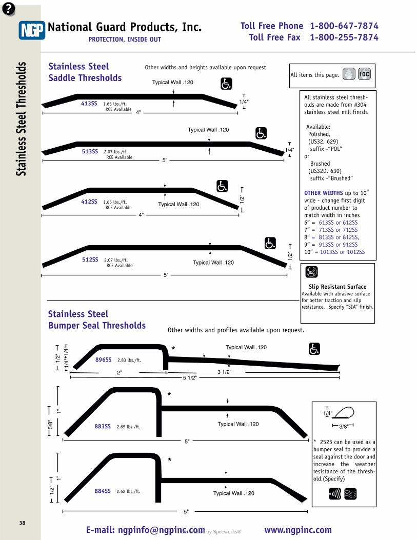
Toll Free Phone 1-800-647-7874Toll Free Fax 1-800-255-7874
E-mail: [email protected] www.ngpinc.com
Stain
less S
teel
Thre
shold
s
38
National Guard Products, Inc.PROTECTION, INSIDE OUT
Typical Wall .120
1/4"
4"
Typical Wall .120
1/4"
5"
413SS 1.65 lbs./ft.RCE Available
513SS 2.07 lbs./ft.RCE Available
Typical Wall .120 1/2"
4"
412SS 1.65 lbs./ft.RCE Available
Typical Wall .120
1/2"
5"
512SS 2.07 lbs./ft.RCE Available
1"
5/8"
5"
Typical Wall .120
*
883SS 2.65 lbs./ft.
1/2"
5"
Typical Wall .120
1"
*
884SS 2.62 lbs./ft.
1/4"
3/8"
* 2525 can be used as abumper seal to provide aseal against the door andincrease the weatherresistance of the thresh-old.(Specify)
Stainless SteelSaddle Thresholds
Other widths and profiles available upon request.
Other widths and heights available upon request
All stainless steel thresh-olds are made from #304stainless steel mill finish.
Available:Polished, (US32, 629)suffix -”POL”
orBrushed
(US32D, 630)suffix -”Brushed”
OTHER WIDTHS up to 10”wide - change first digitof product number tomatch width in inches 6” = 613SS or 612SS7” = 713SS or 712SS8” = 813SS or 812SS,9” = 913SS or 912SS10” = 1013SS or 1012SS
Typical Wall .120
1/4"
*1/4"
5 1/2"
1/2"
3 1/2"2"
Stainless SteelBumper Seal Thresholds
896SS 2.83 lbs./ft.
All items this page. 10C
Slip Resistant SurfaceAvailable with abrasive surfacefor better traction and slipresistance. Specify “SIA” finish.
PDF created by Specworks®
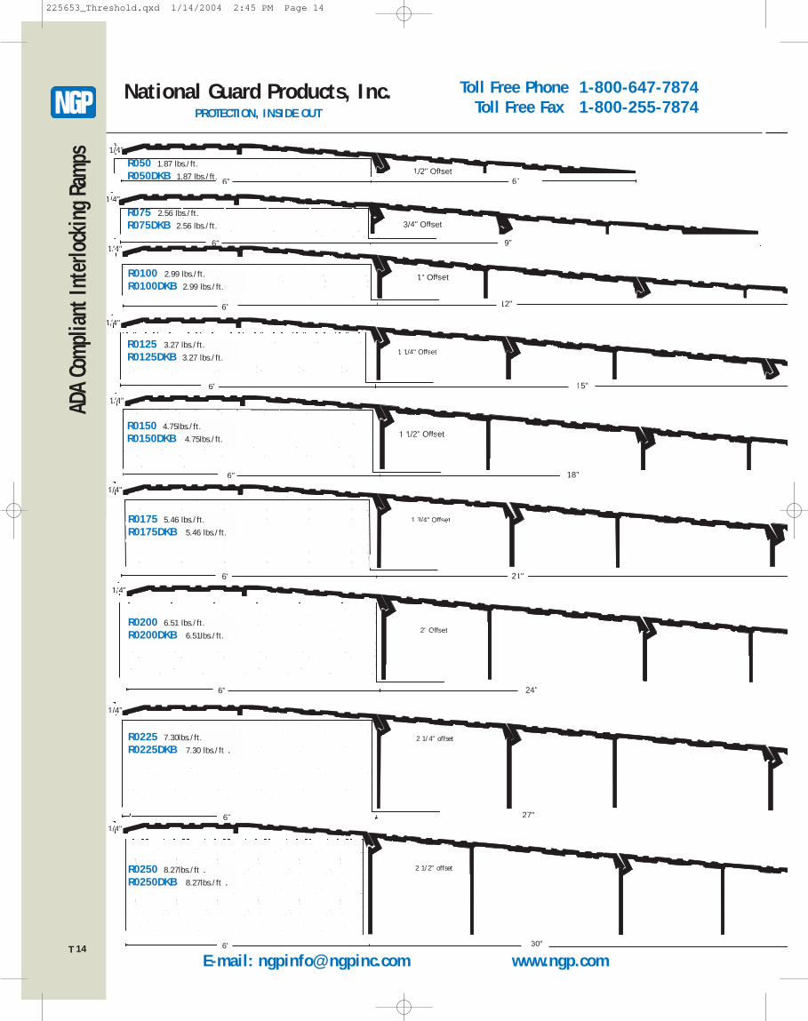
Toll Free Phone 1-800-647-7874Toll Free Fax 1-800-255-7874
E-mail: [email protected] www.ngp.com
National Guard Products, Inc.PROTECTION, INSIDE OUT
ADA
Comp
liant
Inte
rlock
ing
Ramp
s
14
1/4"
1/2" Offset6" 6"
R050 1.87 lbs./ft.
R050DKB 1.87 lbs./ft.
12"
1/4"
1" Offset
6"
R0100 2.99 lbs./ft.
R0100DKB 2.99 lbs./ft.
15"
1/4"
1 1/4" Offset
6"
R0125 3.27 lbs./ft.
R0125DKB 3.27 lbs./ft.
1/4"
18"
1 1/2" Offset
6"
R0150 4.75lbs./ft.
R0150DKB 4.75lbs./ft.
1/4"
1 3/4" Offset
6" 21"
R0175 5.46 lbs./ft.
R0175DKB 5.46 lbs./ft.
1/4"
2" Offset
6" 24"
R0200 6.51 lbs./ft.
R0200DKB 6.51lbs./ft.
30"
1/4"
6"
R0250 8.27lbs./ft .R0250DKB 8.27lbs./ft .
1/4"
3/4" Offset
6" 9"
R075 2.56 lbs./ft.
R075DKB 2.56 lbs./ft.
27"
1/4"
6"
R0225 7.30lbs./ft.
R0225DKB 7.30 lbs./ft .2 1/4” offset
2 1/2” offset
T
225653_Threshold.qxd 1/14/2004 2:45 PM Page 14
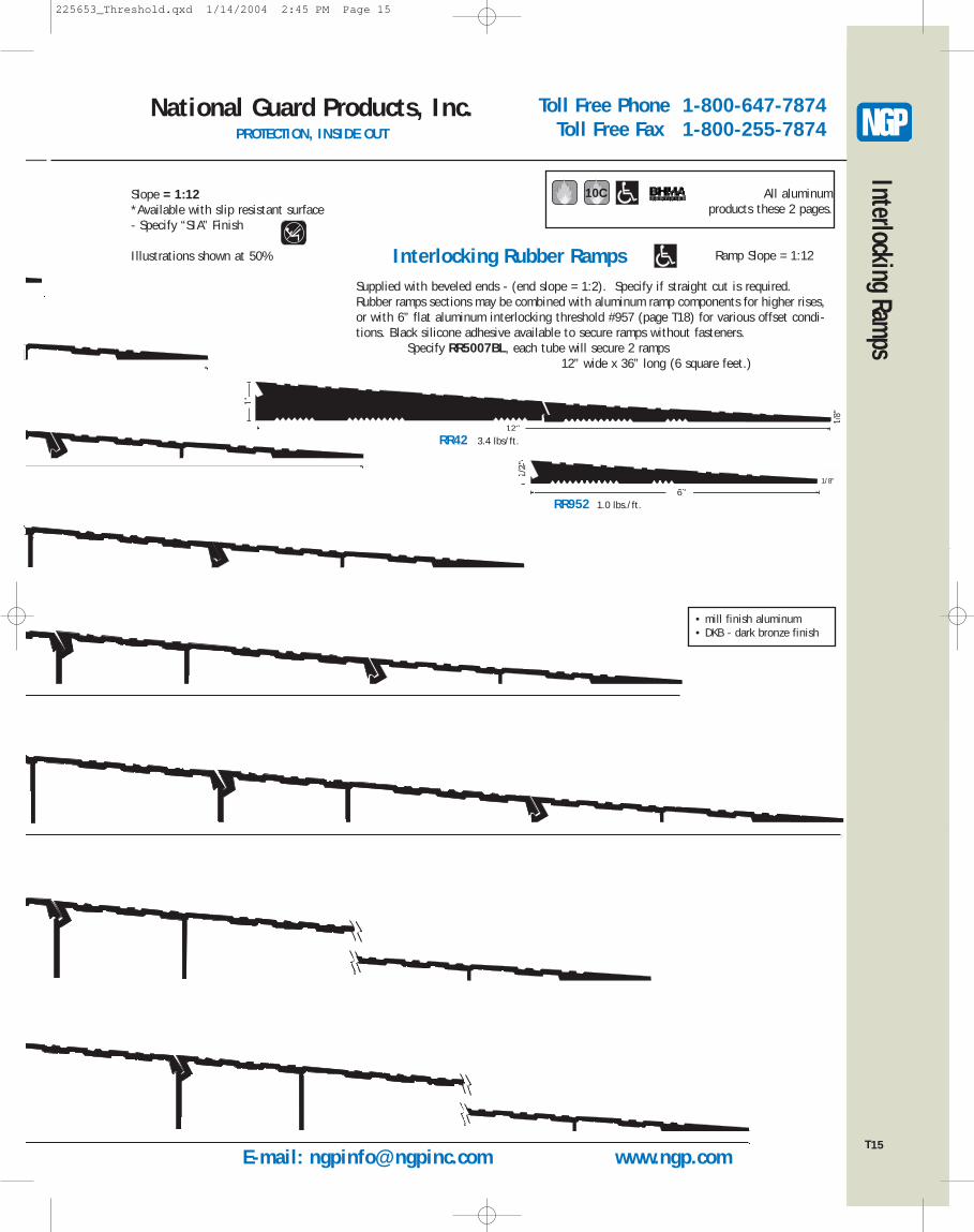
Toll Free Phone 1-800-647-7874Toll Free Fax 1-800-255-7874
National Guard Products, Inc.PROTECTION, INSIDE OUT
15
Interlocking Ramps
• mill finish aluminum• DKB - dark bronze finish
6"
1/2"
1/8"
RR952 1.0 lbs./ft.
12"
1"
1/8"
RR42 3.4 lbs/ft.
1/8”
Ramp Slope = 1:12
Supplied with beveled ends - (end slope = 1:2). Specify if straight cut is required.Rubber ramps sections may be combined with aluminum ramp components for higher rises,or with 6” flat aluminum interlocking threshold #957 (page T18) for various offset condi-tions. Black silicone adhesive available to secure ramps without fasteners.
Specify RR5007BL, each tube will secure 2 ramps 12” wide x 36” long (6 square feet.)
Slope = 1:12*Available with slip resistant surface- Specify “SIA” Finish
Illustrations shown at 50%
All aluminumproducts these 2 pages.
10C
Interlocking Rubber Ramps
TE-mail: [email protected] www.ngp.com
225653_Threshold.qxd 1/14/2004 2:45 PM Page 15
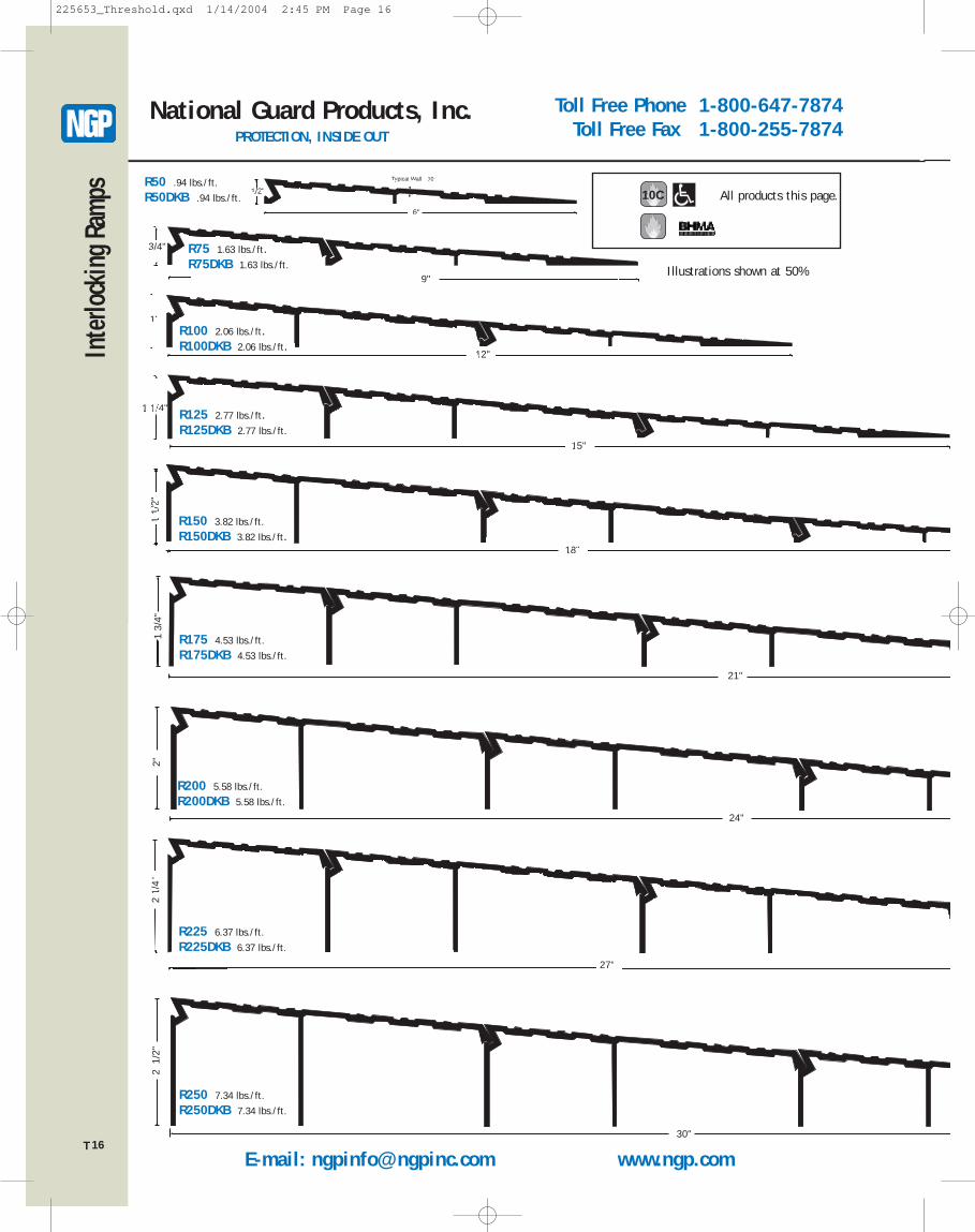
Toll Free Phone 1-800-647-7874Toll Free Fax 1-800-255-7874
E-mail: [email protected] www.ngp.com
National Guard Products, Inc.PROTECTION, INSIDE OUT
Inte
rlock
ing
Ramp
s
16
3/4"
9"
R75 1.63 lbs./ft.R75DKB 1.63 lbs./ft.
1"
12"
R100 2.06 lbs./ft.R100DKB 2.06 lbs./ft.
15"
1 1/4" R125 2.77 lbs./ft.R125DKB 2.77 lbs./ft.
18"
1 1/
2"
R150 3.82 lbs./ft.
R150DKB 3.82 lbs./ft.
21"
1 3/
4"
R175 4.53 lbs./ft.
R175DKB 4.53 lbs./ft.
24"
2"
R200 5.58 lbs./ft.
R200DKB 5.58 lbs./ft.
27"
2 1/
4"
R225 6.37 lbs./ft.
R225DKB 6.37 lbs./ft.
30"
2 1
/2"
R250 7.34 lbs./ft.
R250DKB 7.34 lbs./ft.
Illustrations shown at 50%
6"
1/2"
Typical Wall .110R50 .94 lbs./ft.
R50DKB .94 lbs./ft. All products this page. 10C
T
225653_Threshold.qxd 1/14/2004 2:45 PM Page 16
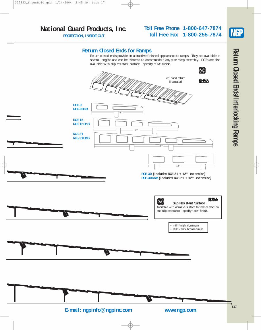
E-mail: [email protected] www.ngp.com
Toll Free Phone 1-800-647-7874Toll Free Fax 1-800-255-7874
National Guard Products, Inc.PROTECTION, INSIDE OUT
17
Return Closed Ends/Interlocking Ramps
Return Closed Ends for Ramps
15"
21"
12"
RCE-30 (includes RCE-21 + 12” extension)RCE-30DKB (includes RCE-21 + 12” extension)
RCE-21RCE-21DKB
RCE-15RCE-15DKB
Return closed ends provide an attractive finished appearance to ramps. They are available inseveral lengths and can be trimmed to accommodate any size ramp assembly. RCE’s are alsoavailable with slip resistant surface. Specify “SIA” finish.
Slip Resistant SurfaceAvailable with abrasive surface for better tractionand slip resistance. Specify “SIA” finish.
left hand returnillustrated
9"
RCE-9RCE-9DKB
T
• mill finish aluminum• DKB - dark bronze finish
225653_Threshold.qxd 1/14/2004 2:45 PM Page 17
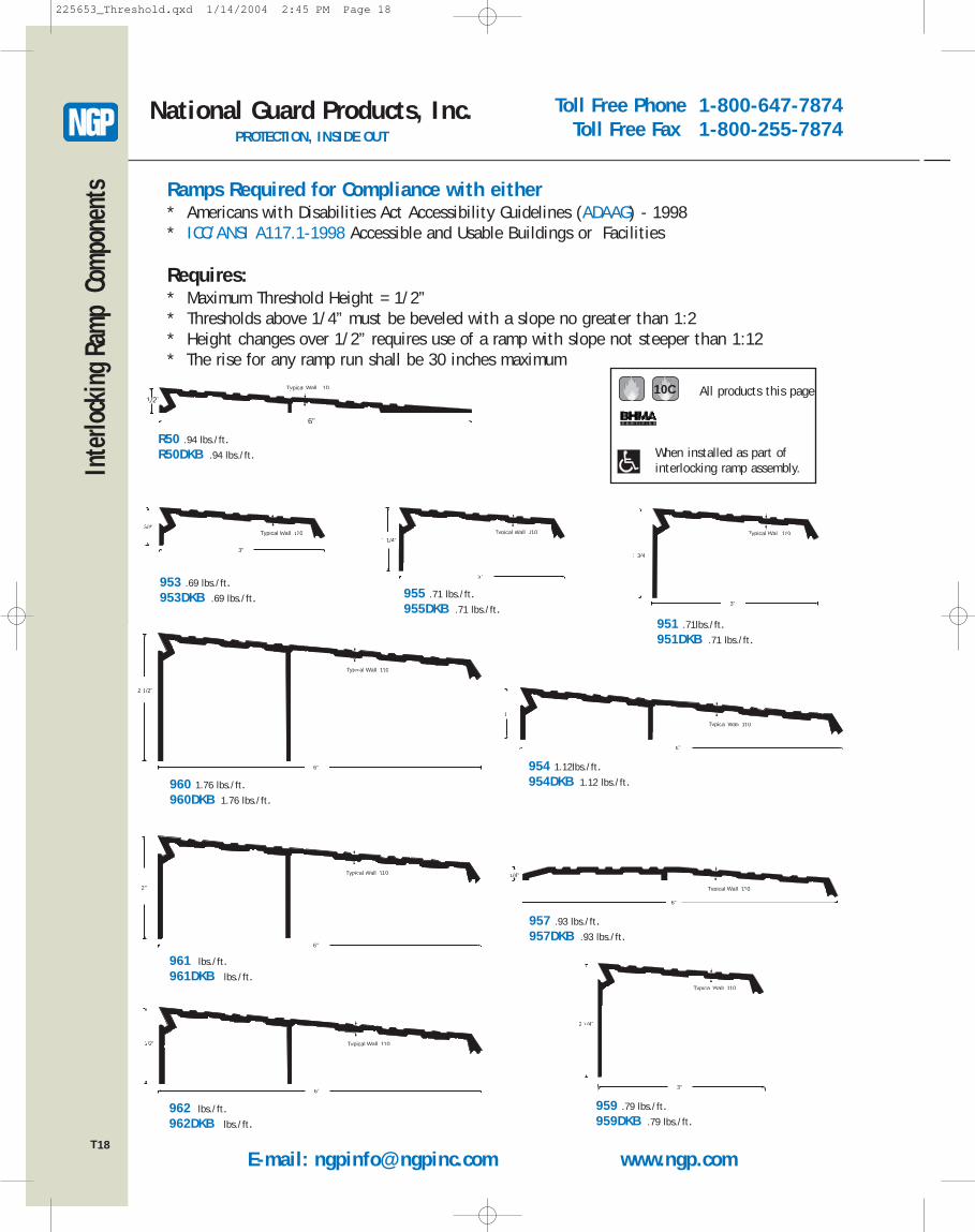
Toll Free Phone 1-800-647-7874Toll Free Fax 1-800-255-7874
E-mail: [email protected] www.ngp.com
National Guard Products, Inc.PROTECTION, INSIDE OUT
18
Inte
rlock
ing
Ramp
Com
pone
nts
3"
3/4"Typical Wall .110
953 .69 lbs./ft.953DKB .69 lbs./ft.
1"
6"
Typical Wall .110
954 1.12lbs./ft.954DKB 1.12 lbs./ft.
3"
1 1/4"Typical Wall .110
955 .71 lbs./ft.955DKB .71 lbs./ft.
1/4"
6"
Typical Wall .110
957 .93 lbs./ft.957DKB .93 lbs./ft.
1 3/4 "
Typical Wall .110
3"
951 .71lbs./ft.951DKB .71 lbs./ft.
2 1/4"
Typical Wall .110
3"
959 .79 lbs./ft.959DKB .79 lbs./ft.
2 1/2"
Typical Wall .110
6"
960 1.76 lbs./ft.960DKB 1.76 lbs./ft.
2"
Typical Wall .110
6"
961 lbs./ft.961DKB lbs./ft.
1/2" Typical Wall .110
6"
962 lbs./ft.962DKB lbs./ft.
Ramps Required for Compliance with either* Americans with Disabilities Act Accessibility Guidelines (ADAAG) - 1998* ICC/ANSI A117.1-1998 Accessible and Usable Buildings or Facilities
Requires:* Maximum Threshold Height = 1/2”* Thresholds above 1/4” must be beveled with a slope no greater than 1:2* Height changes over 1/2” requires use of a ramp with slope not steeper than 1:12* The rise for any ramp run shall be 30 inches maximum
10C
R50 .94 lbs./ft.R50DKB .94 lbs./ft.
6"
1/2"
Typical Wall .110 All products this page
When installed as part of interlocking ramp assembly.
T
225653_Threshold.qxd 1/14/2004 2:45 PM Page 18
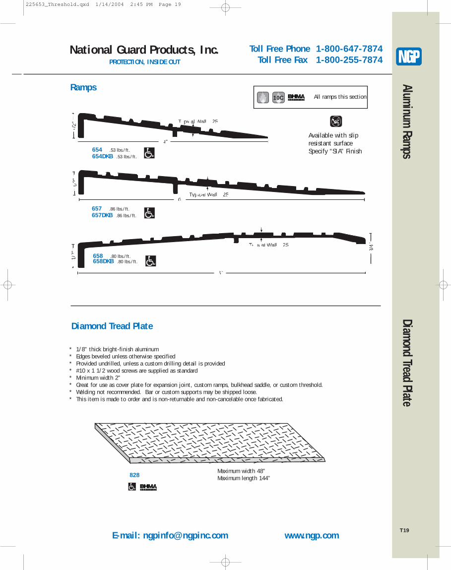
E-mail: [email protected] www.ngp.com
Toll Free Phone 1-800-647-7874Toll Free Fax 1-800-255-7874
National Guard Products, Inc.PROTECTION, INSIDE OUT
19
Aluminum Ramps Diamond Tread Plate
4"
Typical Wall .125
1/2"
654 .53 lbs./ft.654DKB .53 lbs./ft.
6"Typical Wall .125
1/2"
657 .86 lbs./ft.657DKB .86 lbs./ft.
6"
Typical Wall .125
1/2"
3/4"
658 .80 lbs./ft.658DKB .80 lbs./ft.
RampsAll ramps this section10C
Available with slipresistant surfaceSpecify “SIA” Finish
Diamond Tread Plate
* 1/8” thick bright-finish aluminum* Edges beveled unless otherwise specified* Provided undrilled, unless a custom drilling detail is provided* #10 x 1 1/2 wood screws are supplied as standard* Minimum width 2”* Great for use as cover plate for expansion joint, custom ramps, bulkhead saddle, or custom threshold.* Welding not recommended. Bar or custom supports may be shipped loose.* This item is made to order and is non-returnable and non-cancelable once fabricated.
828Maximum width 48”Maximum length 144”
T
225653_Threshold.qxd 1/14/2004 2:45 PM Page 19
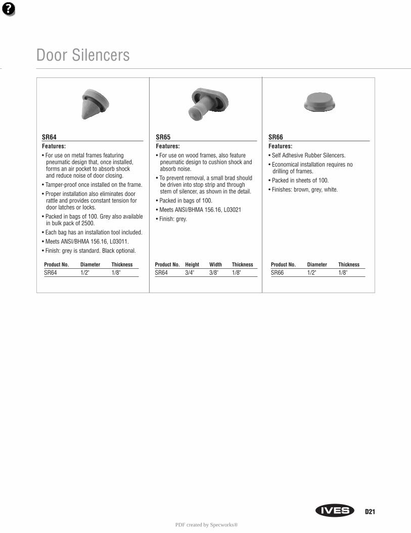
Door Silencers
SR64Features:• For use on metal frames featuring
pneumatic design that, once installed,forms an air pocket to absorb shock and reduce noise of door closing.
• Tamper-proof once installed on the frame.• Proper installation also eliminates door
rattle and provides constant tension fordoor latches or locks.
• Packed in bags of 100. Grey also availablein bulk pack of 2500.
• Each bag has an installation tool included.• Meets ANSI/BHMA 156.16, L03011.• Finish: grey is standard. Black optional.
SR65Features:• For use on wood frames, also feature
pneumatic design to cushion shock andabsorb noise.
• To prevent removal, a small brad shouldbe driven into stop strip and throughstem of silencer, as shown in the detail.
• Packed in bags of 100.• Meets ANSI/BHMA 156.16, L03021• Finish: grey.
SR66Features:• Self Adhesive Rubber Silencers.• Economical installation requires no
drilling of frames.• Packed in sheets of 100.• Finishes: brown, grey, white.
Product No. Diameter ThicknessSR64 1/2" 1/8"
Product No. Height Width ThicknessSR64 3/4" 3/8" 1/8"
Product No. Diameter ThicknessSR66 1/2" 1/8"
D21
PDF created by Specworks®
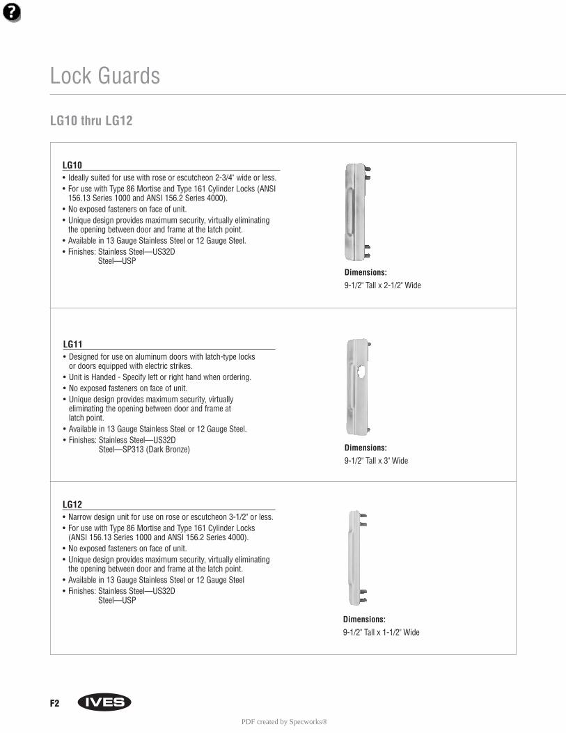
F2
Lock Guards
LG10 • Ideally suited for use with rose or escutcheon 2-3/4" wide or less.• For use with Type 86 Mortise and Type 161 Cylinder Locks (ANSI
156.13 Series 1000 and ANSI 156.2 Series 4000).• No exposed fasteners on face of unit.• Unique design provides maximum security, virtually eliminating
the opening between door and frame at the latch point.• Available in 13 Gauge Stainless Steel or 12 Gauge Steel.• Finishes: Stainless Steel—US32D
Steel—USP
LG12 • Narrow design unit for use on rose or escutcheon 3-1/2" or less.• For use with Type 86 Mortise and Type 161 Cylinder Locks
(ANSI 156.13 Series 1000 and ANSI 156.2 Series 4000).• No exposed fasteners on face of unit.• Unique design provides maximum security, virtually eliminating
the opening between door and frame at the latch point.• Available in 13 Gauge Stainless Steel or 12 Gauge Steel • Finishes: Stainless Steel—US32D
Steel—USP
LG10 thru LG12
LG11• Designed for use on aluminum doors with latch-type locks
or doors equipped with electric strikes.• Unit is Handed - Specify left or right hand when ordering.• No exposed fasteners on face of unit.• Unique design provides maximum security, virtually
eliminating the opening between door and frame at latch point.
• Available in 13 Gauge Stainless Steel or 12 Gauge Steel.• Finishes: Stainless Steel—US32D
Steel—SP313 (Dark Bronze)
Dimensions:
9-1/2" Tall x 2-1/2" Wide
Dimensions:
9-1/2" Tall x 3" Wide
Dimensions:
9-1/2" Tall x 1-1/2" Wide
PDF created by Specworks®


