Measurement of thermal neutron flux using indium foil activation method By Mutturaj Hosamani* and N. M. Badiger Department of Studies in Physics Karnatak University, Dharwad 580003, India *Email: [email protected]Article Abstract The thermal neutron flux (Ф th ) of Am-Be neutron source has been measured by adopting the foil activation method. The neutrons emitted from Am-Be source are used to activate 115 In foil and the gamma radiations emitted from 116m1 In are measured with NaI(Tl) and HPGe detectors. The thermal neutron flux is measured by adopting cadmium (Cd) foil difference technique in which the Cd foil is placed in front of the source to prevent the thermal neutrons interaction with indium foil. The neutron flux is determined by measuring the gamma radiation using a low resolution NaI(Tl) and high resolution HPGe detectors. The measured thermal neutron flux obtained from both detectors has been compared. Keywords Thermal neutron flux; Indium foil; Neutron irradiation; Indium foil irradiation; Activation; Cadmium difference method. Introduction It is well known that neutron is an uncharged particle and does not interact directly with the electrons of matter and hence it difficult to detect directly. The indirect methods such as recoil technique or nuclear reaction are used for detection purposes which are shown in (Tab. 1). The foil activation technique is also used for detecting neutron; in the technique the neutron is allowed to absorb by the nucleus to from compound nucleus. From the compound nucleus, the emitted particles such as beta or gamma radiation are measured. The foil activation method by neutron is one of the best methods to measure the neutron flux. In the present paper we have used neutron activation method to measure the thermal neutron flux using NaI(Tl) and HPGe detectors. Neutrons can be generated by several methods like nuclear reaction, nuclear reactors, spontaneous fission, photoneutron source and alpha-beryllium source (Krane, 1988). Among these Am-Be is alpha-beryllium source which emits neutrons from thermal neutrons (0.025 eV) to around fast neutrons (10 MeV) (Murata et al, 2014), the neutron
Transcript
Measurement of thermal neutron flux using indium foil activation method
By
Mutturaj Hosamani* and N. M. Badiger Department of Studies in Physics Karnatak University, Dharwad 580003, India
It is well known that neutron is an uncharged particle and does not interact directly with the
electrons of matter and hence it difficult to detect directly. The indirect methods such as recoil
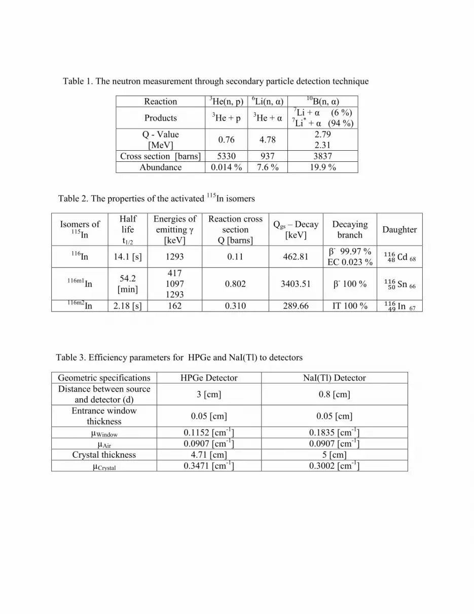
technique or nuclear reaction are used for detection purposes which are shown in (Tab. 1). The
foil activation technique is also used for detecting neutron; in the technique the neutron is
allowed to absorb by the nucleus to from compound nucleus. From the compound nucleus, the
emitted particles such as beta or gamma radiation are measured. The foil activation method by
neutron is one of the best methods to measure the neutron flux.
In the present paper we have used neutron activation method to measure the thermal neutron flux
using NaI(Tl) and HPGe detectors. Neutrons can be generated by several methods like nuclear
reaction, nuclear reactors, spontaneous fission, photoneutron source and alpha-beryllium source
(Krane, 1988). Among these Am-Be is alpha-beryllium source which emits neutrons from
thermal neutrons (0.025 eV) to around fast neutrons (10 MeV) (Murata et al, 2014), the neutron
energy spectrum of the source is shown in (Fig. 1). The alpha particles of 5.486 MeV from 241Am incident on 9Be foil which has relatively loosely bound neutron with binding energy of 1.7
MeV, the neutrons are emitted through the following reaction:
9Be + α → n + 12C* + Q (5.704 MeV)
In the present work, we have used Am−Be neutron source which has activity 105 neutrons per
second (Mudhole et al, 1975). And has been kept in a 15” × 10” cylindrical paraffin container
for neutron shielding.
Theory
The stable isotope of 115In has been irradiated by neutrons from Am−Be source to form
radioactive indium such as 116In, 116m1In and 116m2In with half lives 14.1 second, 54.2 minute and
2.18 second respectively (Akhlaghi et al, 2013). The properties of activated indium isomers are
shown in (Tab. 2). From the (Tab. 2), we notice that the half lives and cross section for formation
of 116In and 116m2In are short and low, and hence we have not considered these two nuclei in
present work (Grazhulene et al, 1992). By adopting cadmium difference method, spatial thermal
neutron flux of Am−Be has been evaluated by considering 116m1In nucleus only. The formation
and decay of 116m1In is shown below:
115In + 1n → 116m1In → 116Sn + γ‘s
We wish to mention that 116m1In has high neutron absorption cross-section for thermal neutron
and relatively long half life of 54.2 min.
When thin indium foil of mass m, irradiated for time ti and it becomes radioactive. The activated
indium foil is allowed to cool for some time to avoid the contribution of 116In and 116m2In
(Grazhulene et al, 1992) and this time is called delay time td. The nuclear radiation emitted from
the activated foil is counted for time tc by using High Purity Germanium (HPGe) and NaI(Tl)
detectors for gamma activity to measure the thermal neutron flux (Фth) of Am-Be neutron source.
Experimental technique
In the present investigations, the stable 115In foil of thickness 1 mm, size 2.5 × 2.5 cm and mass
4.6 gm with purity 99.9 % has been used. It is well known that the Am-Be neutron source emits
neutrons in the energy range from thermal to fast neutrons (Kluge et al, 1982). But our objective
is to measure the flux of thermal neutrons. It is well known that the Cd is good absorber of the
thermal neutrons. In the present work, we have used Cd foil to stop the thermal neutrons
interaction with indium foil and only epithermal and fast neutrons can activate indium foil. Using
Cd foil of appropriate thickness, we have obtained countrate with and without Cd foil. And from
this we have obtained the difference countrate. In the present experiment the gamma rays from 116m1In has been measured using gamma ray spectrometers. Of course the gamma counting has
an advantage that their penetration power is more.
a) Thermal neutron flux measurement using HPGe detectors
For measurement of neutron flux we have used foil activation method in which the neutrons
from the Am-Be are made to interact with 115In. The activated indium has three isotopes namely 116In, 116m1In and 116m2In. Of these 116m1In has long lifetime of about 54.2 min. So we have used
the gamma radiation emitted from 116m1In to determine the neutron flux. We have used ORTEC
make HPGe detector (GMXIOP) which has crystal diameter of 49.6 mm, length 47.1 mm. This
detector is covered with beryllium window of thickness 0.5 mm. The detector has an energy
resolution of 564 eV at 1.8 keV and 1.77 keV at 1.33 MeV. The experimental arrangement for
flux measurement is shown in (Fig. 2). The output of the detector is fed to spectroscopic
amplifier and then to ORTEC makes 16K MCA. We have calibrated this detector using the
gamma radiations emitted from 137Cs, 22Na and 60Co. The calibration curve is shown in (Fig. 3),
and the calibration constant comes out to be 0.4089 keV/Channel. We have determined the
thermal neutron flux using HPGe detector, the flux equation for HPGe detector is given as;
(Akhlaghi et al, 2013):
Ф�� = �� λ
�� σ�� є �γ �����λ�����λ�������λ��� (1)
Where No is difference in count rate obtained in HPGe detector without placing the Cd foil and
with placing the Cd foil in front of indium foil. The typical spectrums of gamma radiation
recorded by the detector without Cd and with Cd are shown in (Fig. 5). The λ is the decay
constant, є is the overall efficiency of the detector, σth is the thermal absorption cross-section for
indium foil which is 202 b, Iγ is the absolute gamma ray intensity (29.2 %) (Grazhulene et al,
1992; Trkov 2013) and NT is the number of target nuclei which is given by
N� =� ��
�� (2)
Here m is the weight of the indium foil, NA is the Avogadro`s number and AM is the atomic
mass of the indium foil. We have determined the efficiency of the detector using the following
equation [Klhma et al. 1952; Dahmani et al. 2014].
є = G × I × M (3)
Where G is the geometrical fraction of the detector window space, that the detector subtends and
I is the fraction of the photons transmitted by the intervening materials that reach the detector
surface, M is the fraction of the photons absorbed by the detector. For right circular cylinder, the
G is given by
G = π��
�π�� (4)
Where πr2 is area of detector face and 4πR2 is the area of sphere with a radius equal to the source
to detector distance. There are losses due to air medium in the path of the particles and detector
window. The intensity of the photons after considering all the losses is given by
I = e�μ������� × e�μ������������� (5)
Where µair linear attenuation coefficient of air, dair distance between source and detector,
µwindow linear attenuation coefficient of detector window, and dwindow is thickness of the detector
window.
The thickness of HPGe detector is not sufficient thick to stop the gamma radiations and therefore
the quantity M is given by
M = 1 − e�μ� (6)
Where µ is the linear attenuation coefficient of the HPGe crystal and d is the thickness of the
crystal. The parameters related the efficiency calculation for HPGe detector is given in (Tab. 3).
Using these parameters efficiency of HPGe detector has been estimated and found to 0.10.
Using No, NT and other quantities, we have estimated the neutron flux and it comes out to be 1.2
n/cm2 sec.
b) Thermal neutron flux measurement using NaI(Tl) detectors
We have used NaI(Tl) detector spectrometer having crystal dimension with 2” × 2” for
determine the neutron flux. Here the detector window is covered with aluminum foil having
thickness 0.05 cm. The energy resolution of the detector is 60 keV at 662 keV . The
experimental arrangement is shown in (Fig. 2). The output of the detector is fed to the linear
amplifier and then to 8K MCA. We have calibrated this detector using the gamma radiations
emitted from 137Cs, 22Na and 60Co. The calibration curve is shown in (Fig. 4), and the calibration
constant comes out to be 1.4568 keV/Channel. Using this detector the flux of neutrons has been
determined. The typical spectrums of gamma radiation recorded by the NaI(Tl) detector without
Cd and with Cd are shown in (Fig. 6). The flux equation for NaI(Tl) detector is given as;
(Akhlaghi et al, 2013).
Ф�� = ��λ
�� σ�� є ��� � �γ (����λ��)��λ��(����λ��) (7)
Here the flux equation is same as equation for HPGe. However the new correction factor, g is
known as the Westcott factor [IAEA 2007] which takes into account the temperature dependence
of flux from the target which is given by 1.019 for indium target. The Gth is the thermal neutron
self shielding factor in foils [Wurdiyanto et al. 1995; Gonalves et al. 2004].
While determining the efficiency of the detector we have used the parameters given in (Tab. 3).
By knowing experimental No, the theoretical NT and other parameters we have determined the
neuron flux (Фth) and it comes out to be 1.4 n/cm2s.
Result and discussion
In the present experiment we have found that the No (1826 by HPGe, 8074 by NaI(Tl) ), the
decay constant λ is 0.0128 per minute, the self shielding factor (Gth) is 0.489 and the Westcott
factor is 1.019 for indium foil. By using these values, as well as thermal neutron absorption
cross-section 202 b values and the detector efficiency, we have determined the thermal neutron
flux (Фth) and it comes out to be 1.3 n/cm2s using two different detectors and same radiations.
From these results we may say that the number of neutrons from Am-Be source incident on
indium foil in per unit area per second is 1.
Conclusion
Thermal neutron flux has been determined using two different detectors with different
efficiencies namely NaI(Tl) and HPGe detectors. In the present work we have adopted the
difference method to measure the flux of thermal neutrons. The measured thermal neutron flux
(Фth) by these two detectors agrees with one another within an error of 15 %. This indicates that
the flux is independent of the type of the detector used. And independent of the resolution of the
detector Therefore we conclude that researchers who do not have HPGe detectors, they may use
NaI(Tl) detector for measuring the thermal neutron flux (Фth).
References
[1]. Krane. K. S, (1988) Introductory nuclear physics, John Wiley & Sons publication`s:
New York.
[2]. Murata. I, Tsuda. I, Nakamura. R, Nakayama. S, Matsumoto. M and Miyamaru. H,
(2014) Neutron and gamma-ray source-term characterization of Am-Be sources in osaka
university, Progress in Nuclear Science and Technology, 4, 345-348.
[3]. Mudhole. T. S and Umakantha. N (1975) Binding energy of the deuteron: A laboratory
experiment, American Journal of Physics, 43(1), 104–105.
[4]. Akhlaghi. P, Rafat-Motavalli. L and Miri-Hakimabad. S. H (2013) The measurements of
thermal neutron flux distribution in a paraffin phantom, Pramana-Journal of Physics,
80(5), 873–885.
[5]. Grazhulene. S. S, Karandashev. V. K, Kuznetsov. R. A (1992) Neutron activation
analysis of indium, Journal of Radioanalytical and Nuclear Chemistry, 158(1), 149–161.
[6]. Kluge. H and Weise. K (1982) The neutron energy spectrum of 241Am − Be(α,n) source
and resulting mean fluence to dose equivalent conversion factors, Radiation protection
dosimetry, 2(2), 85–93.
[7]. Trkov. A, Zerovnik. G, Snoj. L and Ravnik. M (2009) On the self-shielding factors in
neutron activation analysis, Nuclear Instruments and Methods in Physics Research A,
610, 553-565.
[8]. Klhma. E. D. and Ritchie. R. H. (1952) Thermal neutron flux measurements in graphite
using gold and indium foils, Phys Rev, 87, 167.
[9]. Dahmani. B, Kadum. A (2014) Efficiency calculation of NaI(Tl) 2”x2” well detector,
International Journal of Technology Enhancement and Emerging Engineering Research,
2(6), 45 – 47.
[10]. IAEA. (2007) Database of prompt gamma rays from slow neutron capture for elemental
analysis, International Atomic Energy Agency Vienna.
[11]. Wurdiyanto. G, Miyahara. H, Yoshida. A, Yanagida. K, and Mori. C (1995) Precise
measurement of the gamma-ray emission probabilities for 116mIn with half-life of 54.15 min,
Journal of Nuclear Science and Technology, 32(11), 1090–1097.
[12]. Gonalves. I. F, Martinho. E, Salgado. J. (2004) Universal curve of the thermal neutron
self-shielding factor in foils, wires, spheres and cylinders, Journal of Radioanalytical and
Nuclear Chemistry, 261(03), 637–643.
List of captions for figures and tables;
1) Figure 1. Neutron energy spectrum of Am-Be source.
2) Figure 2. Experimental arrangements.
3) Figure 3. Calibration curve of HPGe detector.
4) Figure 4. Calibration curve of NaI(Tl) detector.
5) Figure 5. Measurements using HPGe detector.
a) 115In without Cd foil irradiation.
b) 115In with Cd foil irradiation.
6) Figure 6. Measurements using NaI(Tl) detector.
a) 115In without Cd foil irradiation.
b) 115In with Cd foil irradiation.
7) Table 1. The neutron measurement through secondary particle detection technique.
8) Table 2. The properties of the activated indium 115 isomers.
9) Table 3. Efficiency parameters for HPGe and NaI(Tl) to detectors.
Figure 1. Neutron energy spectrum of Am-Be source
Figure 2. Experimental arrangements
HPGe (D)
L PA HV
SA MCA
Display Activated Indium foil (S)
ADC
NaI(Tl) (D)
PM
LA
HV
MCA
Display Activated Indium foil (S)
Figure 3. Calibration curve of HPGe detector
Figure 4. Calibration curve of NaI(Tl) detector
(a) The spectrum of 115In without b) The spectrum of 115I n with Cd foil
Cd foil irradiation irradiation
Figure 5. Measurements using HPGe detector
(a) The spectrum of 115In without (b) The spectrum of 115In with
Cd foil irradiation Cd foil irradiation
Figure 6. Measurements using NaI(Tl) detector
Table 1. The neutron measurement through secondary particle detection technique