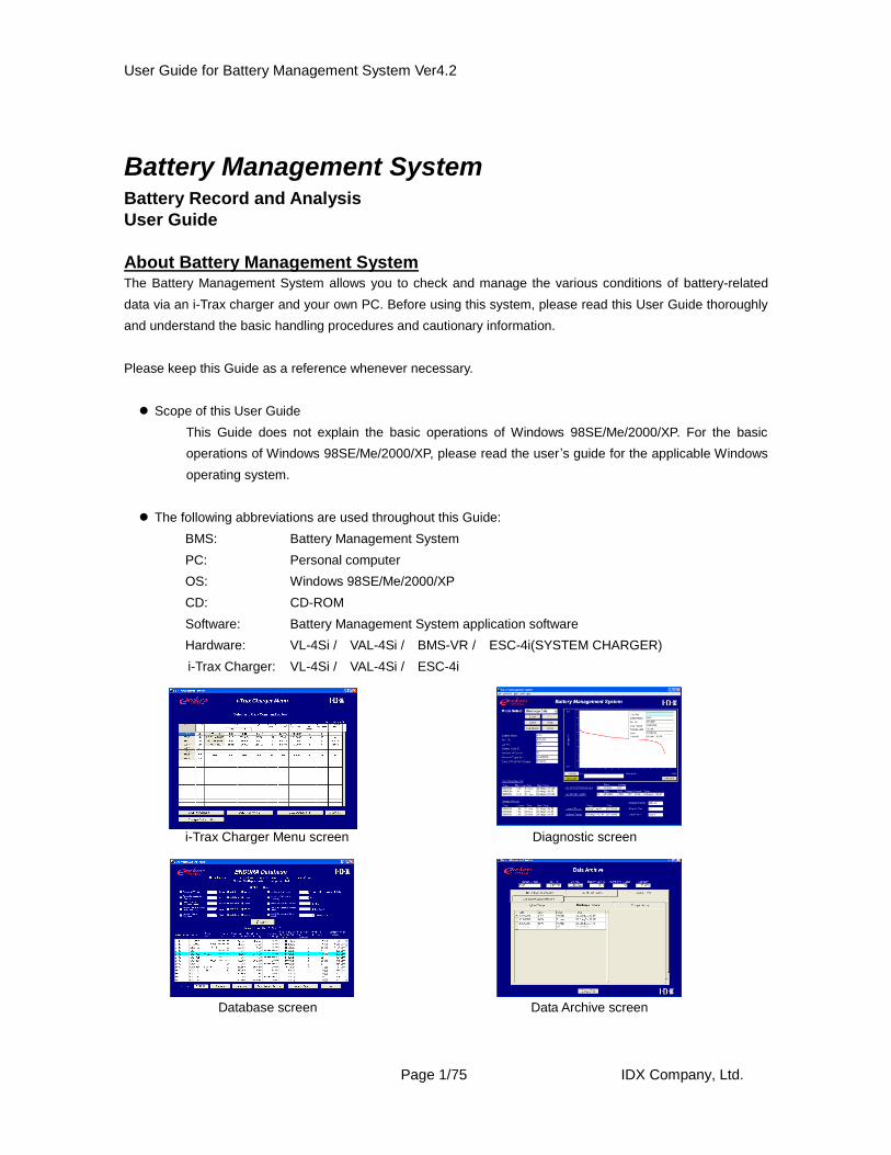
User Guide for Battery Management System Ver4.2 Page 1/75 IDX Company, Ltd. Battery Management System Battery Record and Analysis User Guide About Battery Management System The Battery Management System allows you to check and manage the various conditions of battery-related data via an i-Trax charger and your own PC. Before using this system, please read this User Guide thoroughly and understand the basic handling procedures and cautionary information. Please keep this Guide as a reference whenever necessary. Scope of this User Guide This Guide does not explain the basic operations of Windows 98SE/Me/2000/XP. For the basic operations of Windows 98SE/Me/2000/XP, please read the user ’s guide for the applicable Windows operating system. The following abbreviations are used throughout this Guide: BMS: Battery Management System PC: Personal computer OS: Windows 98SE/Me/2000/XP CD: CD-ROM Software: Battery Management System application software Hardware: VL-4Si / VAL-4Si / BMS-VR / ESC-4i(SYSTEM CHARGER) i-Trax Charger: VL-4Si / VAL-4Si / ESC-4i i-Trax Charger Menu screen Diagnostic screen Database screen Data Archive screen
Transcript
User Guide for Battery Management System Ver4.2
Page 1/75 IDX Company, Ltd.
Battery Management System Battery Record and Analysis
User Guide
About Battery Management System
The Battery Management System allows you to check and manage the various conditions of battery-related
data via an i-Trax charger and your own PC. Before using this system, please read this User Guide thoroughly
and understand the basic handling procedures and cautionary information.
Please keep this Guide as a reference whenever necessary.
Scope of this User Guide
This Guide does not explain the basic operations of Windows 98SE/Me/2000/XP. For the basic
operations of Windows 98SE/Me/2000/XP, please read the user ’s guide for the applicable Windows
operating system.
The following abbreviations are used throughout this Guide:
BMS: Battery Management System
PC: Personal computer
OS: Windows 98SE/Me/2000/XP
CD: CD-ROM
Software: Battery Management System application software
4. USB cable A USB cable is needed to connect each device to a PC.
5. BMS software CD This CD is required when installing the BMS program. It is also
required to uninstall the dedicated USB driver.
6. Batteries supported by the BMS The details are explained below (as of Dec 01, 2008)
1) Batteries supported by the BMS (1)
E-50 (serial numbers F019001 and after)
E-80 (serial numbers A306301 and after)
E-10 (serial numbers C330001 and after)
E-7 (all serial numbers)
ELITE (all serial numbers)
E-HL9 (all serial numbers)
2) Batteries supported by the BMS (2)
E-50 (serial numbers F015001 to F019000)
E-80 (serial numbers A306300 and before)
Please refer Page 58 for the details.
3) Batteries not supported by BMS
E-50 (all batteries whose serial number starts with an alphabet between A and E)
All other batteries
7. Adobe Acrobat Reader Adobe Acrobat Reader is needed to display the Online Manual.
User Guide for Battery Management System Ver4.2
Page 5/75 IDX Company, Ltd.
CHAPTER 2. Installing the Software
Notes for Installation Installation must occur in the following order:
1. Installation of software
2. Installation of USB driver
If this order is reversed, the system may not operate properly. Therefore, until you are instructed to do so,
do not connect the USB cable. Please close all applications on your PC before installing the BMS
The BMS has been developed for a screen resolution of 1024x768. Lower resolutions will prevent you from
seeing the entire screen on the monitor, necessitating scrolling. To avoid this inconvenience, use a screen
resolution of 1024x768 or higher.
If your PC is part of a local area network, certain restrictions may apply in the installation of software (this
has to do with the administrator authorities). If so, please check with the network administrator before
installing the BMS.
The following instructions are organized by Operating System, due to the different installation procedures
for each system.
User Guide for Battery Management System Ver4.2
Page 6/75 IDX Company, Ltd.
1. Installing in a PC running Windows XP
Important: If you are installing the BMS software in a PC that is part of a local area network, be sure to log in as
an Administrator or other user having the proper administrator authority over the applicable local
computer. If the software is installed by a user having no proper authority, some files may not be
copied correctly and errors may generate.
1-1. Insert the Battery Management System CD into the CD-ROM drive of your PC.
1-2. On the following screen, click Japanese if you are installing the Japanese version, or click English if you
are installing the English version.
Note: If you are not using the Japanese-language version of Windows, only English can be selected.
1-3. The License Agreement screen will appear. Click Yes if you accept the terms of the agreement.
User Guide for Battery Management System Ver4.2
Page 7/75 IDX Company, Ltd.
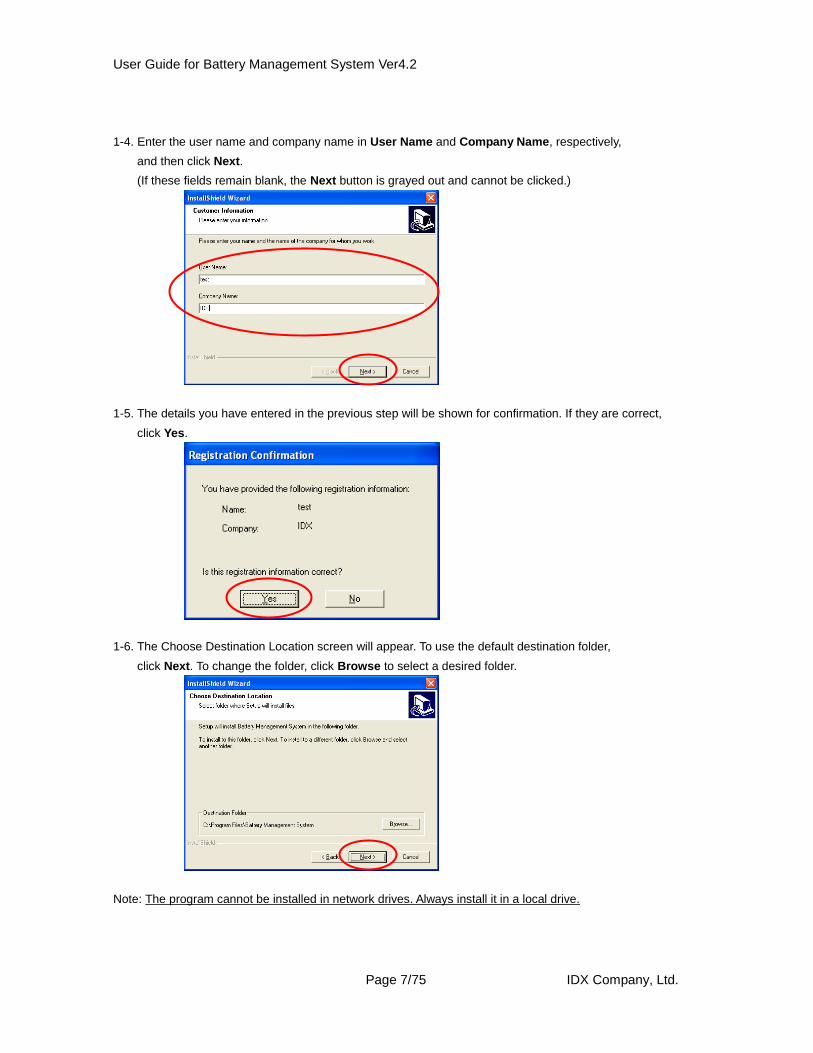
1-4. Enter the user name and company name in User Name and Company Name, respectively,
and then click Next.
(If these fields remain blank, the Next button is grayed out and cannot be clicked.)
1-5. The details you have entered in the previous step will be shown for confirmation. If they are correct,
click Yes.
1-6. The Choose Destination Location screen will appear. To use the default destination folder,
click Next. To change the folder, click Browse to select a desired folder.
Note: The program cannot be installed in network drives. Always install it in a local drive.
User Guide for Battery Management System Ver4.2
Page 8/75 IDX Company, Ltd.
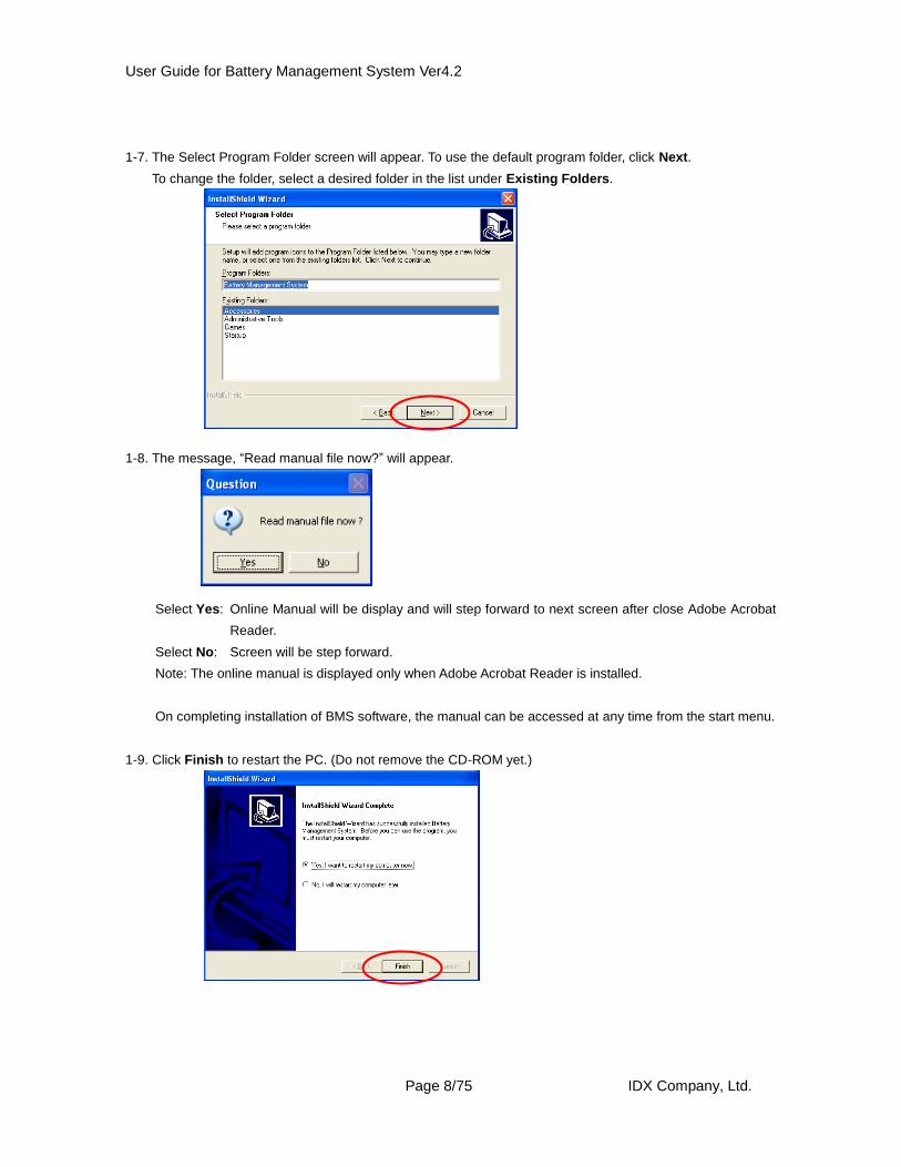
1-7. The Select Program Folder screen will appear. To use the default program folder, click Next.
To change the folder, select a desired folder in the list under Existing Folders.
1-8. The message, “Read manual file now?” will appear.
Select Yes: Online Manual will be display and will step forward to next screen after close Adobe Acrobat
Reader.
Select No: Screen will be step forward.
Note: The online manual is displayed only when Adobe Acrobat Reader is installed.
On completing installation of BMS software, the manual can be accessed at any time from the start menu.
1-9. Click Finish to restart the PC. (Do not remove the CD-ROM yet.)
User Guide for Battery Management System Ver4.2
Page 9/75 IDX Company, Ltd.
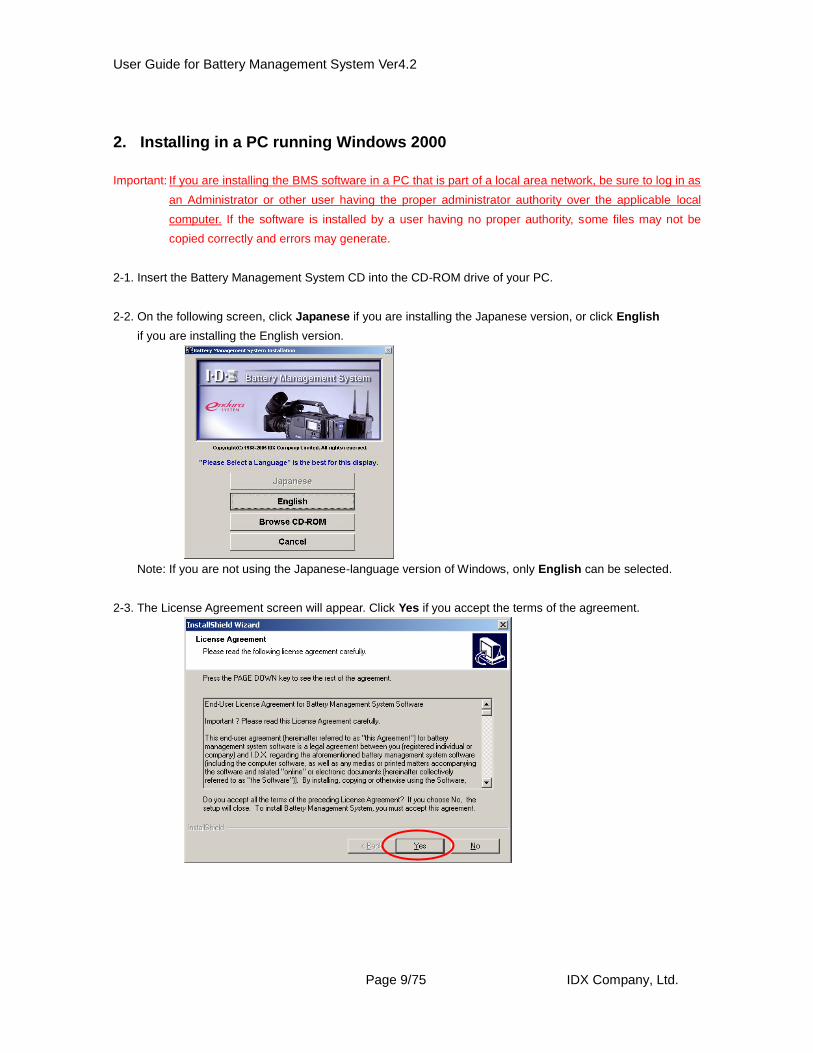
2. Installing in a PC running Windows 2000
Important: If you are installing the BMS software in a PC that is part of a local area network, be sure to log in as
an Administrator or other user having the proper administrator authority over the applicable local
computer. If the software is installed by a user having no proper authority, some files may not be
copied correctly and errors may generate.
2-1. Insert the Battery Management System CD into the CD-ROM drive of your PC.
2-2. On the following screen, click Japanese if you are installing the Japanese version, or click English
if you are installing the English version.
Note: If you are not using the Japanese-language version of Windows, only English can be selected.
2-3. The License Agreement screen will appear. Click Yes if you accept the terms of the agreement.
User Guide for Battery Management System Ver4.2
Page 10/75 IDX Company, Ltd.
2-4. Enter the user name and company name in User Name and Company Name, respectively,
and then click Next.
(If these fields remain blank, the Next button is grayed out and cannot be clicked.)
2-5. The details you have entered in the previous step will be shown for confirmation. If they are correct,
click Yes.
2-6. The Choose Destination Location screen will appear. To use the default destination folder, click Next.
To change the folder, click Browse to select a desired folder.
Note: The program cannot be installed in network drives. Always install it in a local drive.
User Guide for Battery Management System Ver4.2
Page 11/75 IDX Company, Ltd.
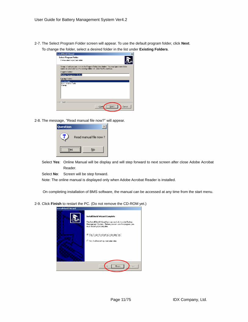
2-7. The Select Program Folder screen will appear. To use the default program folder, click Next.
To change the folder, select a desired folder in the list under Existing Folders.
2-8. The message, “Read manual file now?” will appear.
Select Yes: Online Manual will be display and will step forward to next screen after close Adobe Acrobat
Reader.
Select No: Screen will be step forward.
Note: The online manual is displayed only when Adobe Acrobat Reader is installed.
On completing installation of BMS software, the manual can be accessed at any time from the start menu.
2-9. Click Finish to restart the PC. (Do not remove the CD-ROM yet.)
User Guide for Battery Management System Ver4.2
Page 12/75 IDX Company, Ltd.
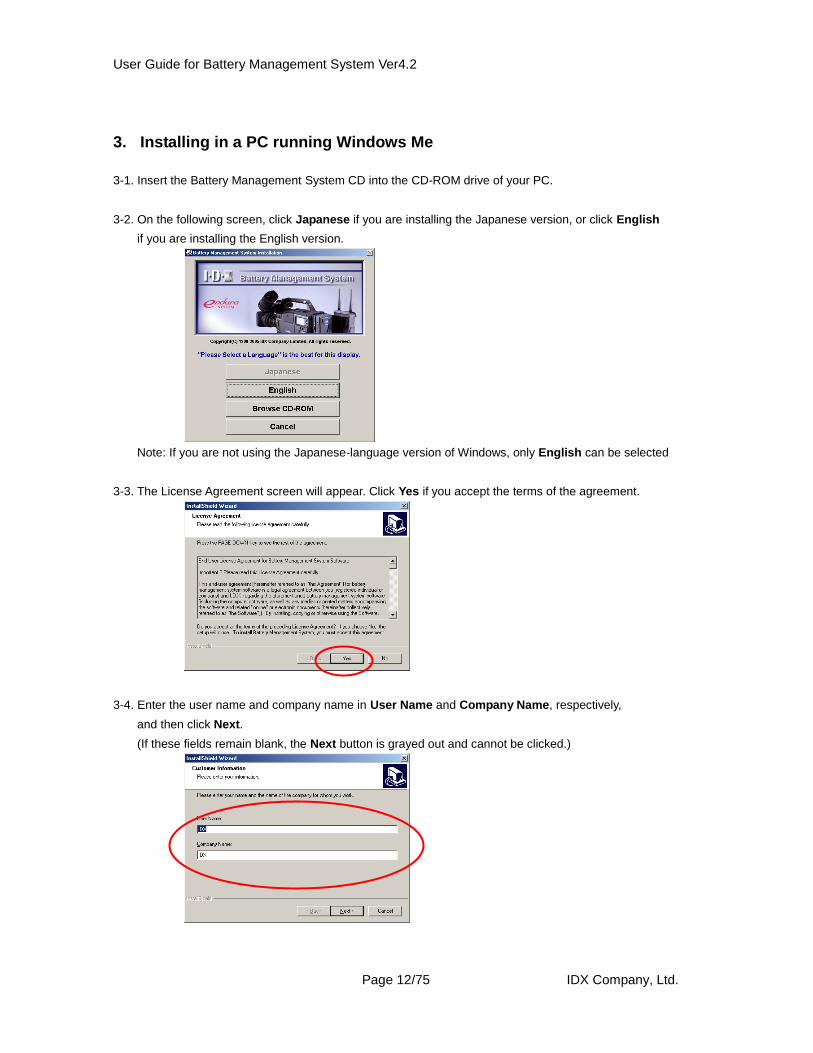
3. Installing in a PC running Windows Me
3-1. Insert the Battery Management System CD into the CD-ROM drive of your PC.
3-2. On the following screen, click Japanese if you are installing the Japanese version, or click English
if you are installing the English version.
Note: If you are not using the Japanese-language version of Windows, only English can be selected
3-3. The License Agreement screen will appear. Click Yes if you accept the terms of the agreement.
3-4. Enter the user name and company name in User Name and Company Name, respectively,
and then click Next.
(If these fields remain blank, the Next button is grayed out and cannot be clicked.)
User Guide for Battery Management System Ver4.2
Page 13/75 IDX Company, Ltd.
3-5. The details you have entered in the previous step will be shown for confirmation. If they are correct,
click Yes.
3-6. The Choose Destination Location screen will appear. To use the default destination folder, click Next.
To change the folder, click Browse to select a desired folder.
Note: The program cannot be installed in network drives. Always install it in a local drive.
3-7. The Select Program Folder screen will appear. To use the default program folder, click Next .
To change the folder, select a desired folder in the list under Existing Folders.
User Guide for Battery Management System Ver4.2
Page 14/75 IDX Company, Ltd.
3-8. The message, “Read manual file now?” will appear.
Select Yes: Online Manual will be display and will step forward to next screen after close Adobe Acrobat
Reader.
Select No: Screen will be step forward.
Note: The online manual is displayed only when Adobe Acrobat Reader is installed.
On completing installation of BMS software, the manual can be accessed at any time from the start menu.
3-9. Click Finish to restart the PC. (Do not remove the CD-ROM yet.)
User Guide for Battery Management System Ver4.2
Page 15/75 IDX Company, Ltd.
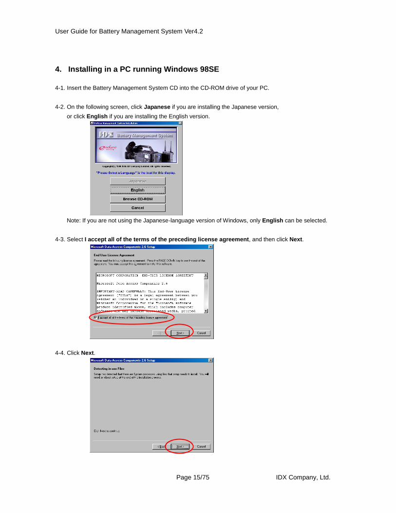
4. Installing in a PC running Windows 98SE
4-1. Insert the Battery Management System CD into the CD-ROM drive of your PC.
4-2. On the following screen, click Japanese if you are installing the Japanese version,
or click English if you are installing the English version.
Note: If you are not using the Japanese-language version of Windows, only English can be selected.
4-3. Select I accept all of the terms of the preceding license agreement, and then click Next.
4-4. Click Next.
User Guide for Battery Management System Ver4.2
Page 16/75 IDX Company, Ltd.
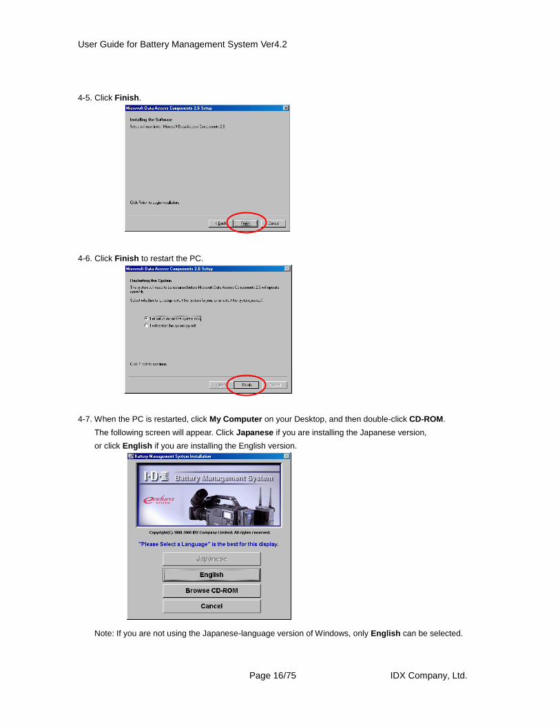
4-5. Click Finish.
4-6. Click Finish to restart the PC.
4-7. When the PC is restarted, click My Computer on your Desktop, and then double-click CD-ROM.
The following screen will appear. Click Japanese if you are installing the Japanese version,
or click English if you are installing the English version.
Note: If you are not using the Japanese-language version of Windows, only English can be selected.
User Guide for Battery Management System Ver4.2
Page 17/75 IDX Company, Ltd.
4-8. Select I accept all of the terms of the preceding license agreement, and then click Next.
4-9. Click Next.
4-10. Click Finish.
4-11. Click Close.
User Guide for Battery Management System Ver4.2
Page 18/75 IDX Company, Ltd.
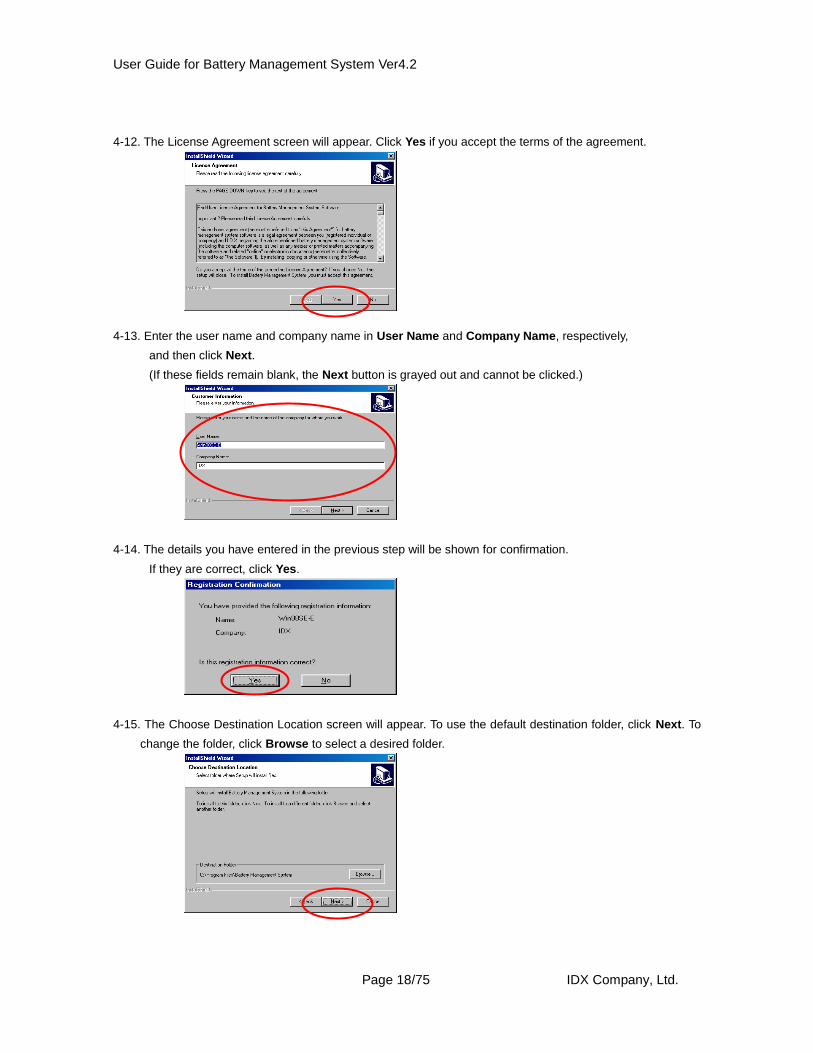
4-12. The License Agreement screen will appear. Click Yes if you accept the terms of the agreement.
4-13. Enter the user name and company name in User Name and Company Name, respectively,
and then click Next.
(If these fields remain blank, the Next button is grayed out and cannot be clicked.)
4-14. The details you have entered in the previous step will be shown for confirmation.
If they are correct, click Yes.
4-15. The Choose Destination Location screen will appear. To use the default destination folder, click Next. To
change the folder, click Browse to select a desired folder.
User Guide for Battery Management System Ver4.2
Page 19/75 IDX Company, Ltd.
Note: The program cannot be installed in network drives. Always install it in a local drive.
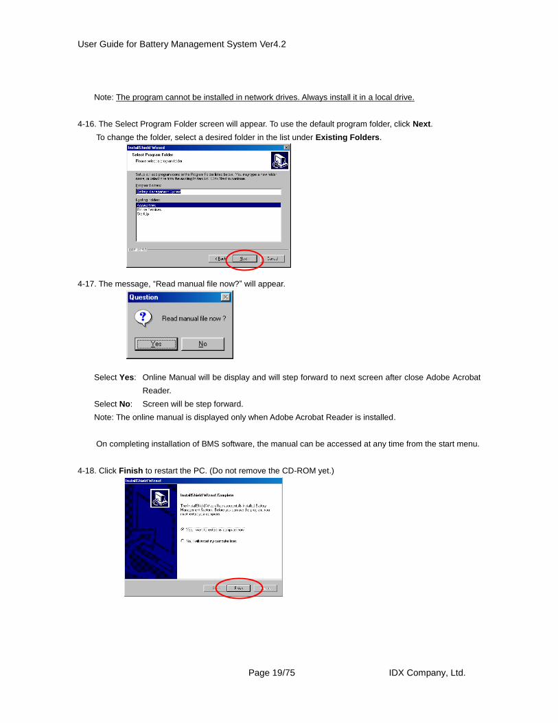
4-16. The Select Program Folder screen will appear. To use the default program folder, click Next.
To change the folder, select a desired folder in the list under Existing Folders.
4-17. The message, “Read manual file now?” will appear.
Select Yes: Online Manual will be display and will step forward to next screen after close Adobe Acrobat
Reader.
Select No: Screen will be step forward.
Note: The online manual is displayed only when Adobe Acrobat Reader is installed.
On completing installation of BMS software, the manual can be accessed at any time from the start menu.
4-18. Click Finish to restart the PC. (Do not remove the CD-ROM yet.)
User Guide for Battery Management System Ver4.2
Page 20/75 IDX Company, Ltd.
CHAPTER 3. Installing the USB Driver
Notes for Installation
The following instructions are organized by operating system, due to the different
installation procedures for each system.
1. Installing the USB driver in a PC running Windows XP
Important: If you are installing the USB driver in a PC that is part of a local area network, be sure to log in as an
Administrator or other user having the proper administrator authority over the applicable local
computer. If the driver is installed by a user having no proper authority, some files may not be copied
correctly and errors may generate.
1-1. Connecting the hardware (ESC-4i/VAL-4Si/VL-4Si/BMS-VR) to your PC via a USB cable
will automatically activate the Found New Hardware Wizard. Click Next.
1-2. After selecting Search for the best driver in these locations, select Include this location in the search,
and then enter “(CD-ROM drive):¥Win2kXP” (for example, if the CD-ROM drive is E, enter “E:¥Win2kXP”).
Click Next.
User Guide for Battery Management System Ver4.2
Page 21/75 IDX Company, Ltd.
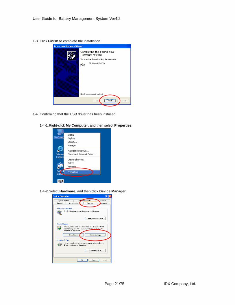
1-3. Click Finish to complete the installation.
1-4. Confirming that the USB driver has been installed.
1-4-1. Right-click My Computer, and then select Properties.
1-4-2. Select Hardware, and then click Device Manager.
User Guide for Battery Management System Ver4.2
Page 22/75 IDX Company, Ltd.
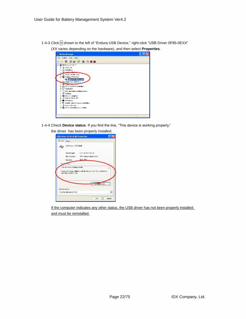
1-4-3. Click + shown to the left of “Endura USB Device,” right-click “USB Driver 0F85-0EXX”
(XX varies depending on the hardware), and then select Properties.
1-4-4. Check Device status. If you find the line, “This device is working properly,”
the driver has been properly installed.
If the computer indicates any other status, the USB driver has not been properly installed
and must be reinstalled.
User Guide for Battery Management System Ver4.2
Page 23/75 IDX Company, Ltd.
2. Installing the USB driver in a PC running Windows 2000
Important: If you are installing the USB driver in a PC that is part of a local area network, be sure to log in as an
Administrator or other user having the proper administrator authority over the applicable local
computer. If the driver is installed by a user having no proper authority, some files may not be copied
correctly and errors may generate.
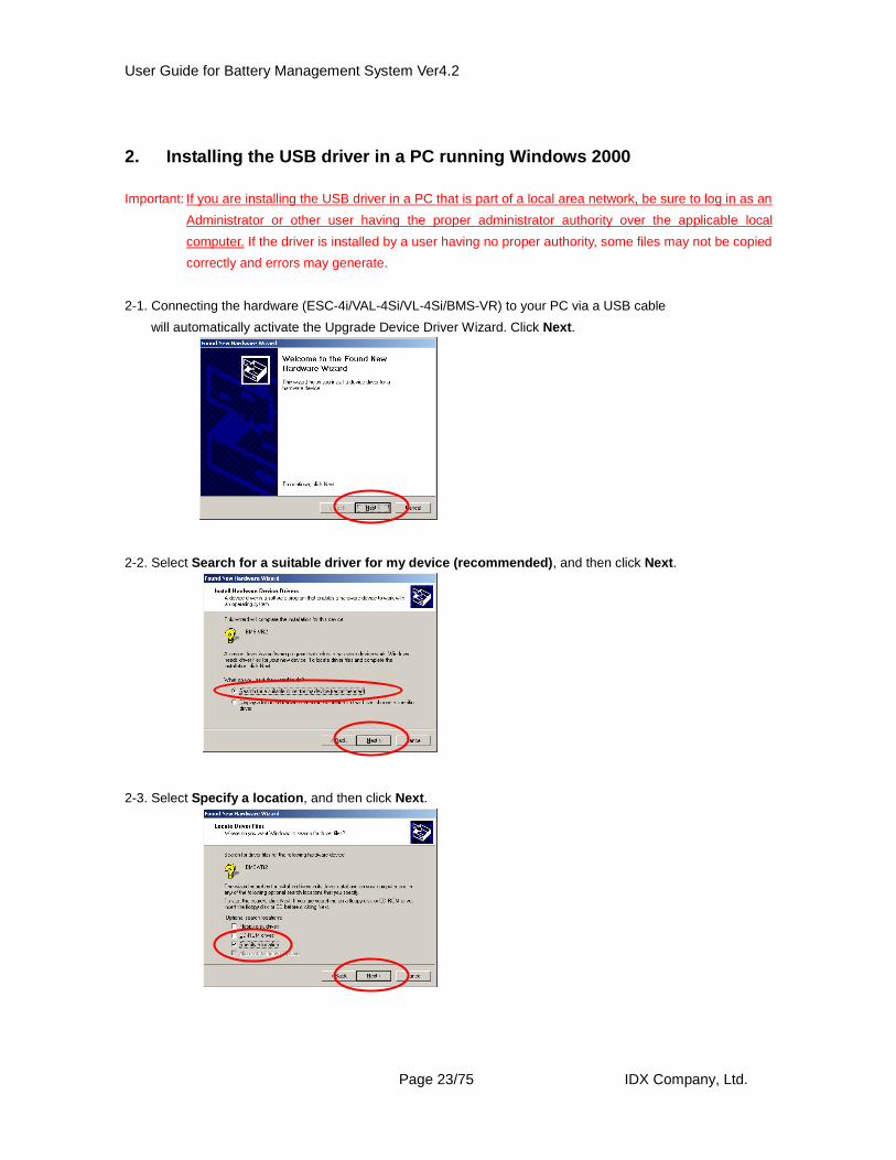
2-1. Connecting the hardware (ESC-4i/VAL-4Si/VL-4Si/BMS-VR) to your PC via a USB cable
will automatically activate the Upgrade Device Driver Wizard. Click Next.
2-2. Select Search for a suitable driver for my device (recommended), and then click Next.
2-3. Select Specify a location, and then click Next.
User Guide for Battery Management System Ver4.2
Page 24/75 IDX Company, Ltd.
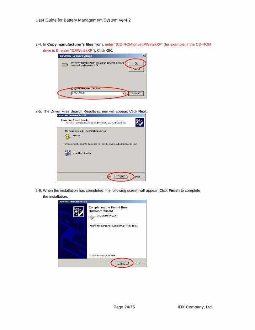
2-4. In Copy manufacturer’s files from, enter “(CD-ROM drive):¥Win2kXP” (for example, if the CD-ROM
drive is E, enter “E:¥Win2kXP”). Click OK.
2-5. The Driver Files Search Results screen will appear. Click Next.
2-6. When the installation has completed, the following screen will appear. Click Finish to complete
the installation.
User Guide for Battery Management System Ver4.2
Page 25/75 IDX Company, Ltd.
2-7. Confirming that the USB driver has been installed.
2-7-1. Right-click My Computer, and then select Properties.
2-7-2. Select Hardware, and then click Device Manager.
2-7-3. Click + shown to the left of “Endura USB Device,” right-click “USB Driver 0F85-0EXX”
(XX varies depending on the hardware), and then select Properties.
User Guide for Battery Management System Ver4.2
Page 26/75 IDX Company, Ltd.
2-7-4. Check Device status. If you find the line, “This device is working properly,”
the driver has been properly installed.
If the computer indicates any other status, the USB driver has not been properly installed and must be reinstalled.
User Guide for Battery Management System Ver4.2
Page 27/75 IDX Company, Ltd.
3. Installing the USB driver in a PC running Windows Me
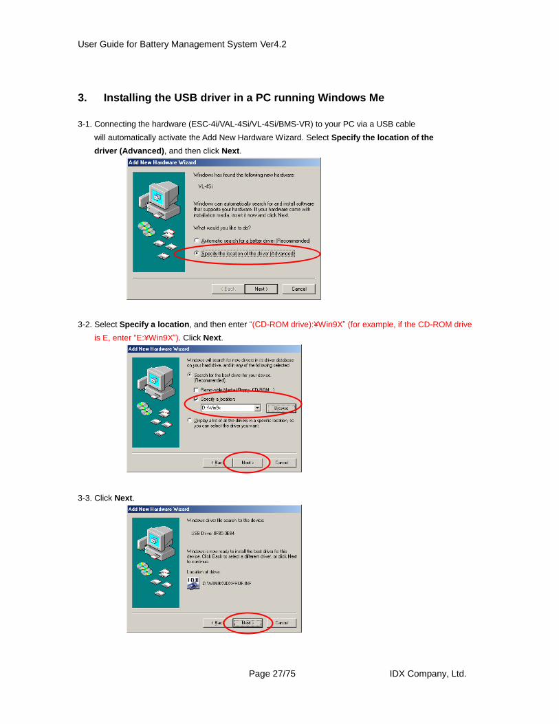
3-1. Connecting the hardware (ESC-4i/VAL-4Si/VL-4Si/BMS-VR) to your PC via a USB cable
will automatically activate the Add New Hardware Wizard. Select Specify the location of the
driver (Advanced), and then click Next.
3-2. Select Specify a location, and then enter “(CD-ROM drive):¥Win9X” (for example, if the CD-ROM drive
is E, enter “E:¥Win9X”). Click Next.
3-3. Click Next.
User Guide for Battery Management System Ver4.2
Page 28/75 IDX Company, Ltd.
3-4. Click Finish to complete the installation.
3-5. Confirming that the USB driver has been installed.
3-5-1. Right-click My Computer, and then select Properties.
3-5-2. After selecting Device Manager, click + shown to the left of “Endura USB Device,”
right-click “USB Driver 0F85-0EXX” (XX varies depending on the hardware),
and then select Properties.
User Guide for Battery Management System Ver4.2
Page 29/75 IDX Company, Ltd.
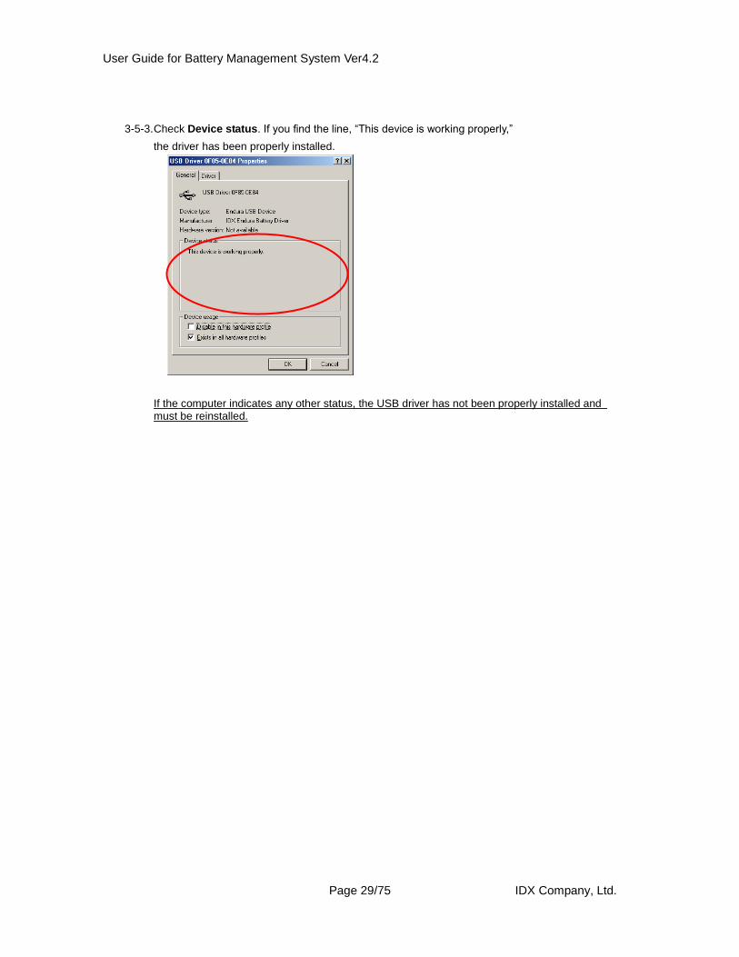
3-5-3. Check Device status. If you find the line, “This device is working properly,”
the driver has been properly installed.
If the computer indicates any other status, the USB driver has not been properly installed and must be reinstalled.
User Guide for Battery Management System Ver4.2
Page 30/75 IDX Company, Ltd.
4. Installing the USB driver in a PC running Windows 98SE
4-1. Connecting the hardware (ESC-4i/VAL-4Si/VL-4Si/BMS-VR) to your PC via a USB cable
will automatically activate the Add New Hardware Wizard. Click Next.
4-2. Select Search for the best driver for your device (Recommended), and then click Next.
4-3. Select Specify a location, and then enter “(CD-ROM drive):/Win9X” (for example, if the CD-ROM drive is
E, enter “E:¥Win9X”). Click Next.
User Guide for Battery Management System Ver4.2
Page 31/75 IDX Company, Ltd.
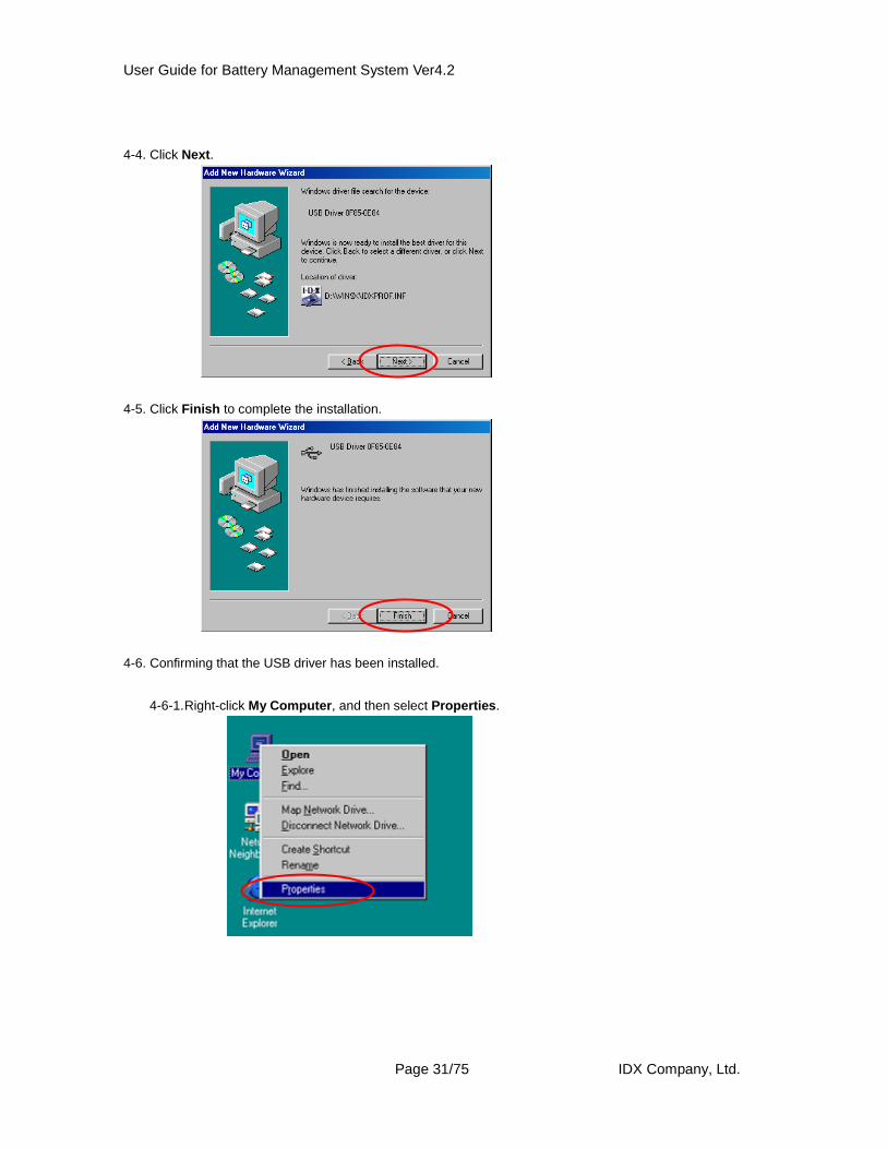
4-4. Click Next.
4-5. Click Finish to complete the installation.
4-6. Confirming that the USB driver has been installed.
4-6-1. Right-click My Computer, and then select Properties.
User Guide for Battery Management System Ver4.2
Page 32/75 IDX Company, Ltd.
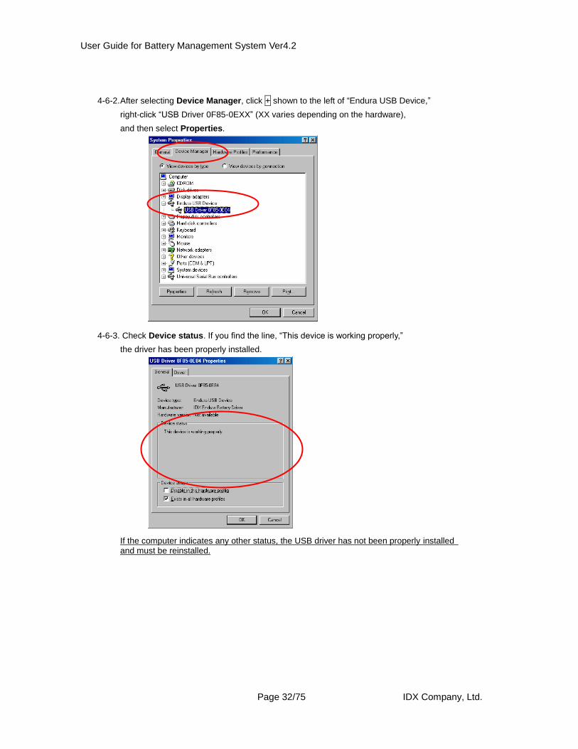
4-6-2. After selecting Device Manager, click + shown to the left of “Endura USB Device,”
right-click “USB Driver 0F85-0EXX” (XX varies depending on the hardware),
and then select Properties.
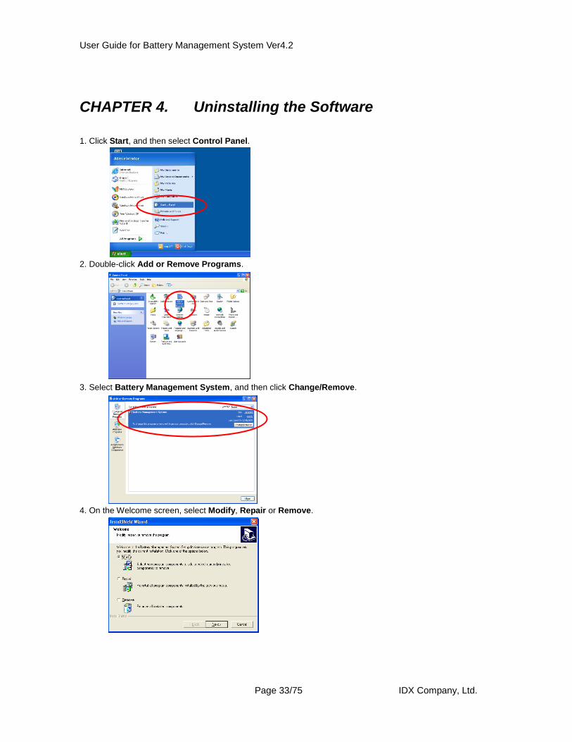
4-6-3. Check Device status. If you find the line, “This device is working properly,”
the driver has been properly installed.
If the computer indicates any other status, the USB driver has not been properly installed and must be reinstalled.
User Guide for Battery Management System Ver4.2
Page 33/75 IDX Company, Ltd.
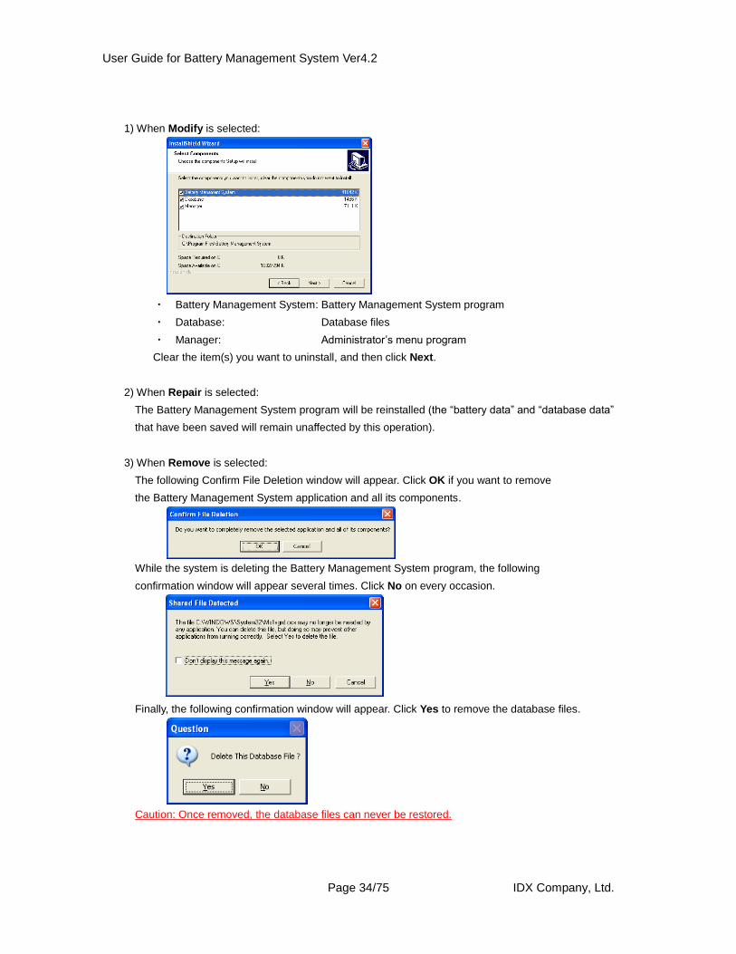
CHAPTER 4. Uninstalling the Software
1. Click Start, and then select Control Panel.
2. Double-click Add or Remove Programs.
3. Select Battery Management System, and then click Change/Remove.
4. On the Welcome screen, select Modify, Repair or Remove.
User Guide for Battery Management System Ver4.2
Page 34/75 IDX Company, Ltd.
1) When Modify is selected:
・ Battery Management System: Battery Management System program
・ Database: Database files
・ Manager: Administrator’s menu program
Clear the item(s) you want to uninstall, and then click Next.
2) When Repair is selected:
The Battery Management System program will be reinstalled (the “battery data” and “database data”
that have been saved will remain unaffected by this operation).
3) When Remove is selected:
The following Confirm File Deletion window will appear. Click OK if you want to remove
the Battery Management System application and all its components.
While the system is deleting the Battery Management System program, the following
confirmation window will appear several times. Click No on every occasion.
Finally, the following confirmation window will appear. Click Yes to remove the database files.
Caution: Once removed, the database files can never be restored.
User Guide for Battery Management System Ver4.2
Page 35/75 IDX Company, Ltd.
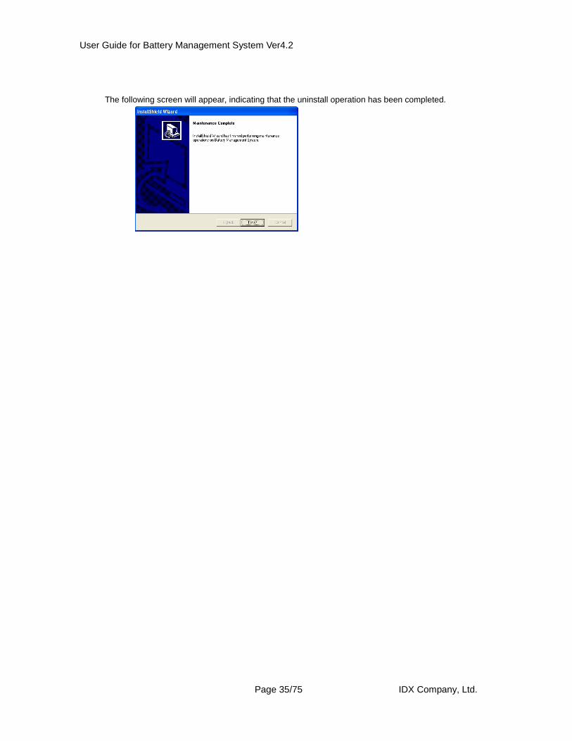
The following screen will appear, indicating that the uninstall operation has been completed.
User Guide for Battery Management System Ver4.2
Page 36/75 IDX Company, Ltd.
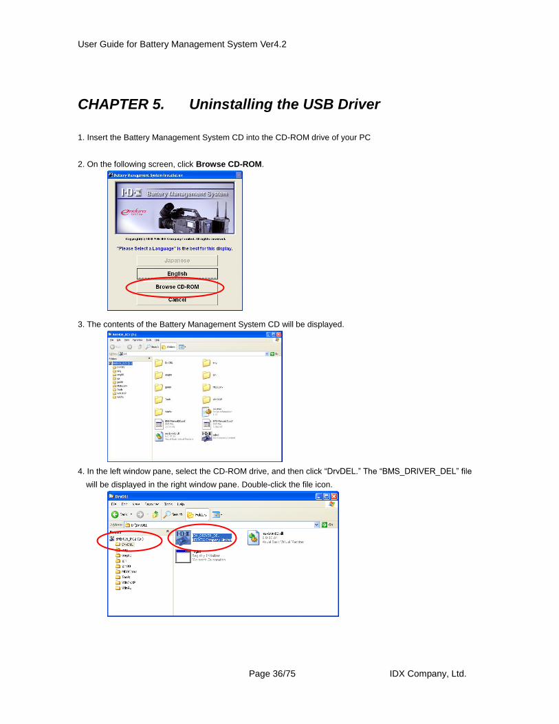
CHAPTER 5. Uninstalling the USB Driver
1. Insert the Battery Management System CD into the CD-ROM drive of your PC
2. On the following screen, click Browse CD-ROM.
3. The contents of the Battery Management System CD will be displayed.
4. In the left window pane, select the CD-ROM drive, and then click “DrvDEL.” The “BMS_DRIVER_DEL” file
will be displayed in the right window pane. Double-click the file icon.
User Guide for Battery Management System Ver4.2
Page 37/75 IDX Company, Ltd.
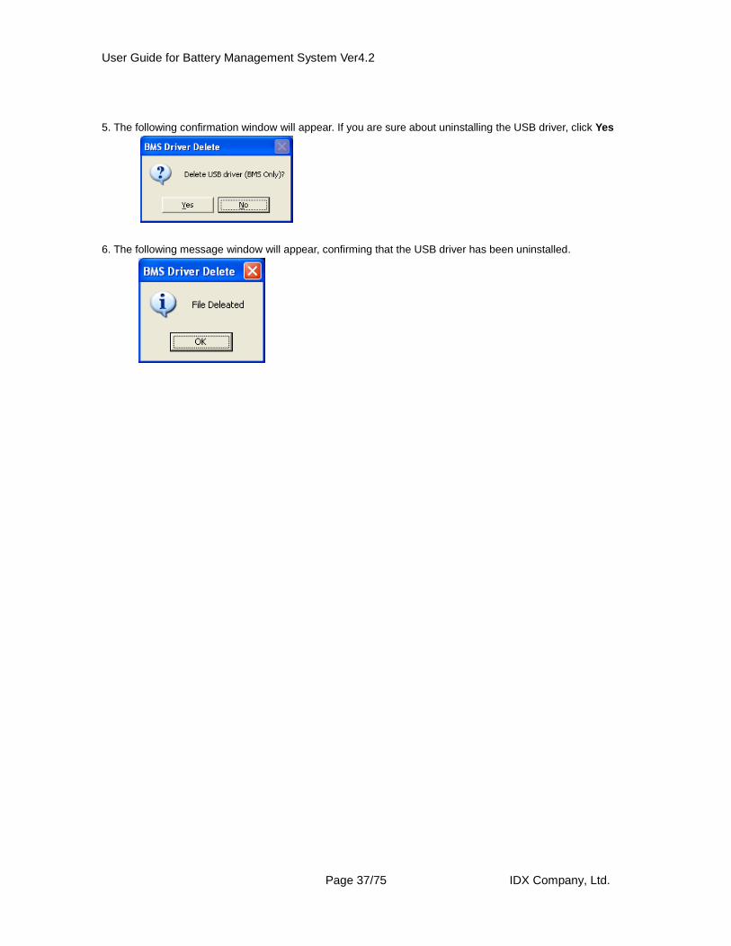
5. The following confirmation window will appear. If you are sure about uninstalling the USB driver, click Yes
6. The following message window will appear, confirming that the USB driver has been uninstalled.
User Guide for Battery Management System Ver4.2
Page 38/75 IDX Company, Ltd.
CHAPTER 6. Starting and Closing the Program
1. Before starting the program Before starting the program, connect the PC to the hardware via a USB cable.
2. Starting the program You can start the program in one of the following methods:
Method 1: By double-clicking the Battery Management System icon on your Desktop.
Method 2: By clicking Start, pointing to All Programs, pointing to Battery Management System,
and then selecting Battery Management System.
3. Closing the program You can close the program in one of the following methods:
Method 1: By clicking Exit in the Main Menu screen.
Method 2: By clicking the close box on the Maim Menu screen
(the x button in the top right-hand corner of the window).
User Guide for Battery Management System Ver4.2
Page 39/75 IDX Company, Ltd.
CHAPTER 7. Items and Functions Available on the
Main Menu Screen
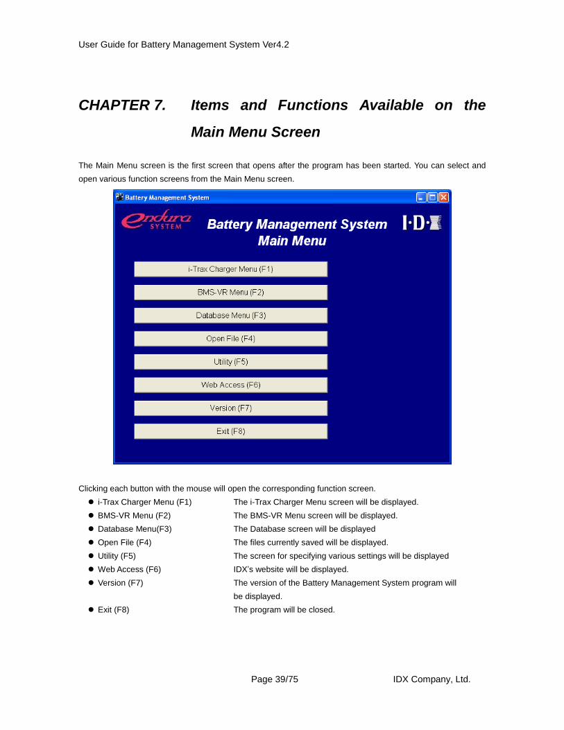
The Main Menu screen is the first screen that opens after the program has been started. You can select and
open various function screens from the Main Menu screen.
Clicking each button with the mouse will open the corresponding function screen.
i-Trax Charger Menu (F1) The i-Trax Charger Menu screen will be displayed.
BMS-VR Menu (F2) The BMS-VR Menu screen will be displayed.
Database Menu(F3) The Database screen will be displayed
Open File (F4) The files currently saved will be displayed.
Utility (F5) The screen for specifying various settings will be displayed
Web Access (F6) IDX’s website will be displayed.
Version (F7) The version of the Battery Management System program will
be displayed.
Exit (F8) The program will be closed.
User Guide for Battery Management System Ver4.2
Page 40/75 IDX Company, Ltd.
CHAPTER 8. Items and Functions Available on the
i-Trax Charger Menu Screen
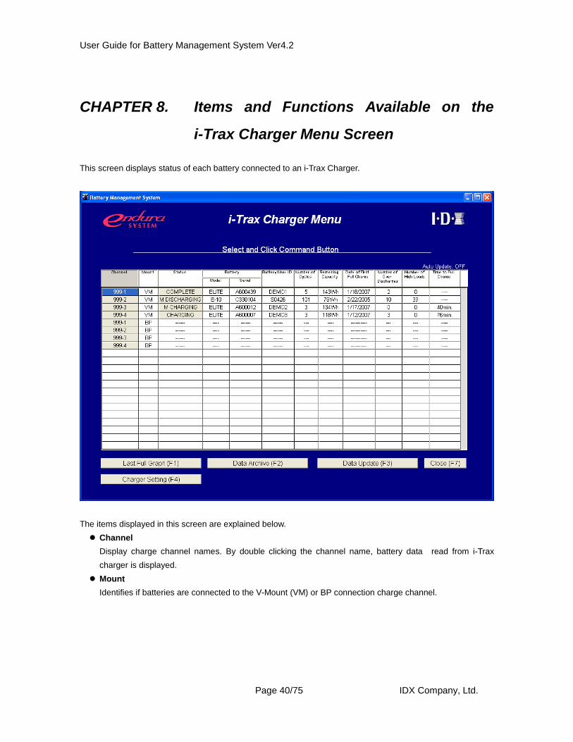
This screen displays status of each battery connected to an i-Trax Charger.
The items displayed in this screen are explained below.
Channel
Display charge channel names. By double clicking the channel name, battery data read from i-Trax
charger is displayed.
Mount
Identifies if batteries are connected to the V-Mount (VM) or BP connection charge channel.
User Guide for Battery Management System Ver4.2
Page 41/75 IDX Company, Ltd.
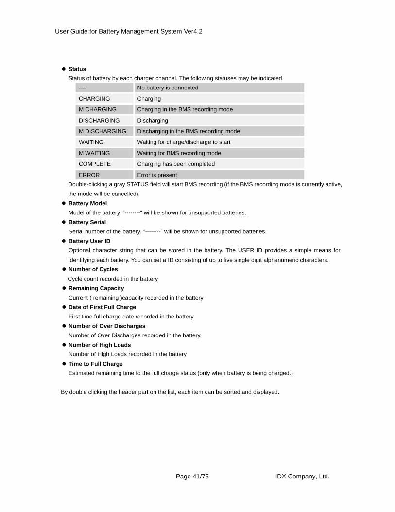
Status
Status of battery by each charger channel. The following statuses may be indicated.
---- No battery is connected
CHARGING Charging
M CHARGING Charging in the BMS recording mode
DISCHARGING Discharging
M DISCHARGING Discharging in the BMS recording mode
WAITING Waiting for charge/discharge to start
M WAITING Waiting for BMS recording mode
COMPLETE Charging has been completed
ERROR Error is present
Double-clicking a gray STATUS field will start BMS recording (if the BMS recording mode is currently active,
the mode will be cancelled).
Battery Model
Model of the battery. “--------“ will be shown for unsupported batteries.
Battery Serial
Serial number of the battery. “--------” will be shown for unsupported batteries.
Battery User ID
Optional character string that can be stored in the battery. The USER ID provides a simple means for
identifying each battery. You can set a ID consisting of up to five single digit alphanumeric characters.
Number of Cycles
Cycle count recorded in the battery
Remaining Capacity
Current ( remaining )capacity recorded in the battery
Date of First Full Charge
First time full charge date recorded in the battery
Number of Over Discharges
Number of Over Discharges recorded in the battery.
Number of High Loads
Number of High Loads recorded in the battery
Time to Full Charge
Estimated remaining time to the full charge status (only when battery is being charged.)
By double clicking the header part on the list, each item can be sorted and displayed.
User Guide for Battery Management System Ver4.2
Page 42/75 IDX Company, Ltd.
You can also access the following function buttons.
Last Full Graph (F1)
This button becomes selectable when a channel connected to a supported battery is selected. Clicking this
button will open the diagnostic screen of the selected battery. If discharge data is available, it will be
displayed. If discharge data is not available, battery data will be displayed. For the Diagnostic screen, refer
to CHAPTER 11.
Data Archive (F2)
This button becomes selectable when a channel connected to a supported battery is selected. Clicking this
button will open the Data Archive screen of the selected battery. For the Data Archive screen, refer to
CHAPTER 12.
Data Update (F3)
Clicking this button will refresh the list and obtain the latest status data from the i-Trax Charger.
Charger Setting (F4)
Clicking this button will display the i-Trax Charger setting screen.
Close (F7)
Clicking this button will close the i-Trax Charger Menu screen and the program will return to the Main Menu
screen.
The i-Trax Charger Menu screen provides other functions, as explained below.
If an auto load interval has been set by selecting Auto Update Interval Setup in the Utility Menu screen,
latest data will be loaded automatically from the i-Trax charger at the specified interval. If the system
detects a battery whose BMS recording has completed, the discharge data of the battery will be
automatically saved to the database (this function is effective only for those batteries supported by the
BMS).
User Guide for Battery Management System Ver4.2
Page 43/75 IDX Company, Ltd.
CHAPTER 9. i-Trax Charger Setting
i-Trax Charger Setting screen, you can set the various items relating to the i-Trax Charger.
The items displayed in this screen are explained below:
Channel
Display Charge Channel Names
Mount
VM/BP type of each charge channel.
Status
Status of battery by each charger channel. The following statuses may be indicated.
---- No battery is connected
CHARGEING Charging
M CHARGEING Charging in the BMS recording mode
DISCHARGEING Discharging
M DISCHARGEING Discharging in the BMS recording mode
WAITING Waiting for charge/discharge to start
User Guide for Battery Management System Ver4.2
Page 44/75 IDX Company, Ltd.
M WAITING Waiting for BMS recording mode
COMPLETE Charging has been completed
ERROR Error is present
Battery Model
Model of the battery. “-------” will be shown for unsupported batteries.
Battery Serial
Serial number of the battery. “--------” will be shown for unsupported batteries.
ADJ
This checkbox is used to enter a User Battery ID and adjust and specify discharge settings. Selecting this
checkbox will make the corresponding User ID and Term. Volt/Discharge Load fields editable.
Selecting the checkbox again will apply the entered settings to the i-Trax Charger.
Battery User ID
Optional character string that can be stored in the battery. The USER ID provides a simple means for
identifying each battery. You can set a character string consisting of up to five single-byte alphanumeric.
Charge Volt
This data is displayed only when the battery is charging. The current charge voltage is indicated
Charge Current
This data is displayed only when the battery is charging. The current charge current is indicated.
Discharge Setting: Term. Volt
The termination voltage is indicated. You can enter a desired value with the ADJ checkbox selected. The
value entered here will become the voltage at which discharge will be terminated (setting range: 10.0 to
14.0 V).
Discharge Setting: Load
The power output is indicated. You can enter a desired value with the ADJ checkbox selected. The value
entered here will become the power output during discharge (setting range: 15 to 45 W).
By double clicking the header part on the list, each item can be sorted and displayed.
You can also access the following function buttons:
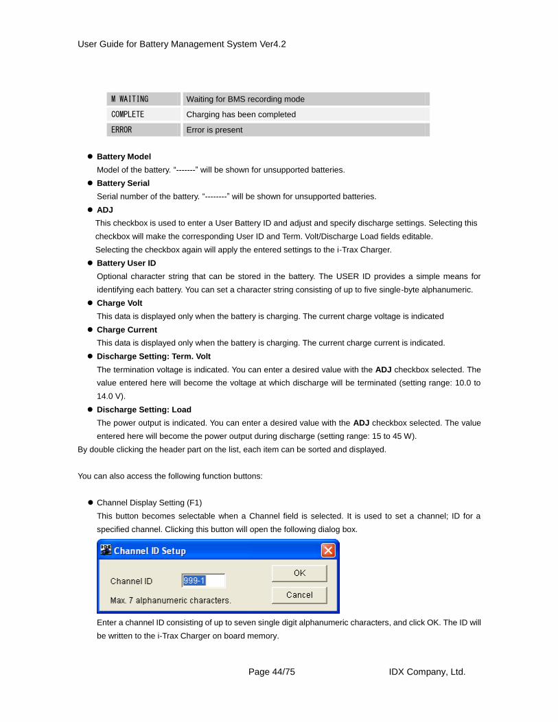
Channel Display Setting (F1)
This button becomes selectable when a Channel field is selected. It is used to set a channel; ID for a
specified channel. Clicking this button will open the following dialog box.
Enter a channel ID consisting of up to seven single digit alphanumeric characters, and click OK. The ID will
be written to the i-Trax Charger on board memory.
User Guide for Battery Management System Ver4.2
Page 45/75 IDX Company, Ltd.
Battery User ID (F2)
This option is highlighted when a supported battery is connected to the channel. A user selected
name or ID can be stored in the battery. The Battery User ID provides a simple means for
identifying each battery.
The following dialogs are displayed for E-50/E-80/E-10/E-7/E-HL9.
You can set a character string consisting of up to five single-byte alphanumeric. When OK button is
clicked, the setting is written into battery.
The following dialogs are displayed for ELITE.
User can input an ID name or code consisting of up to five alphanumeric digits.
In addition for ELITE the user can set a further identifier of up to sixteen digits can be entered.
When OK button is clicked, the setting is written into the batteries memory.
Display Update (F3)
Clicking this button will refresh the list and obtain the latest status data from the i-Trax Charger.
Termination Voltage Setting (F4)
This button becomes selectable when a channel connected to a supported battery is selected.
The i-Trax Charger discharge termination voltage is set. When clicked, the following dialog is displayed.
User Guide for Battery Management System Ver4.2
Page 46/75 IDX Company, Ltd.
Enter a desired Termination Voltage value and then click OK. The setting will be recorded in the i-Trax
Charger.
When the value is changed while “This setting applies to all VM channels” and “This setting applies to all
BP channels “boxes are checked, the same value will be applied to all the channels.
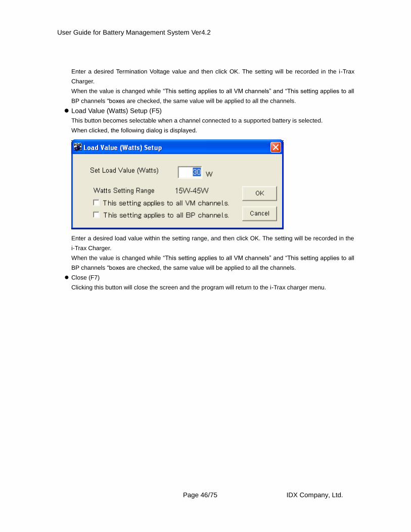
Load Value (Watts) Setup (F5)
This button becomes selectable when a channel connected to a supported battery is selected.
When clicked, the following dialog is displayed.
Enter a desired load value within the setting range, and then click OK. The setting will be recorded in the
i-Trax Charger.
When the value is changed while “This setting applies to all VM channels” and “This setting applies to all
BP channels “boxes are checked, the same value will be applied to all the channels.
Close (F7)
Clicking this button will close the screen and the program will return to the i-Trax charger menu.
User Guide for Battery Management System Ver4.2
Page 47/75 IDX Company, Ltd.
CHAPTER 10. Items and Functions Available on the
BMS-VR Menu Screen
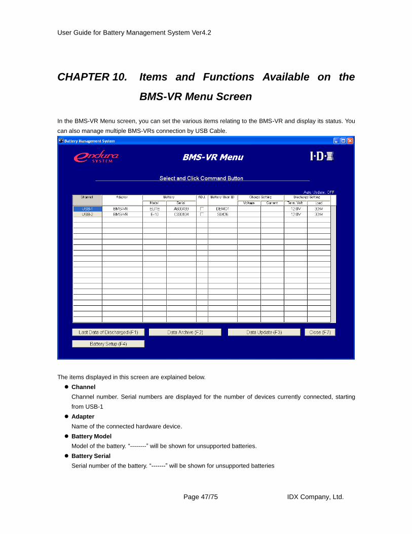
In the BMS-VR Menu screen, you can set the various items relating to the BMS-VR and display its status. You
can also manage multiple BMS-VRs connection by USB Cable.
The items displayed in this screen are explained below.
Channel
Channel number. Serial numbers are displayed for the number of devices currently connected, starting
from USB-1
Adapter
Name of the connected hardware device.
Battery Model
Model of the battery. “--------” will be shown for unsupported batteries.
Battery Serial
Serial number of the battery. “-------” will be shown for unsupported batteries
User Guide for Battery Management System Ver4.2
Page 48/75 IDX Company, Ltd.
ADJ
This checkbox is used to enter a battery user ID and specify discharge settings. Selecting this checkbox
will make the corresponding USER ID and Term Volt/Discharge Load fields editable. Selecting the
checkbox again will display the confirmation screen and by selecting “ yes” will apply the entered settings
to the hardware.
Battery User ID
Optional character string that can be stored in the battery. The USER ID provides a simple means for
identifying each battery. You can set a character string consisting of up to five single-byte alphanumeric.
Charge Voltage
This data is displayed only when the battery is charging. The current charge voltage is indicated.
Charge Current
This data is displayed only when the battery is charging. The current charge current is indicated.
Discharge Term Volt
The termination voltage is indicated. You can enter a desired value with the Change checkbox selected.
This will become the voltage at which discharge will be terminated (setting range: 10.0 to 13.5 V).
Discharge Load
The power output is indicated. You can enter a desired value with the Change checkbox selected. This will
become the power output during discharge (setting range: 13 to 40 W)
You can also access the following function buttons.
Last Data of Discharge (F1)
This button becomes selectable when a channel connected to a battery is selected. Clicking this button will
open the Diagnostic screen of the selected battery. For the Diagnostic screen, refer to CHAPTER 11.
Data Archive (F2)
This button becomes selectable when a channel connected to a supported battery is selected. Clicking this
button will open the Data Archive screen of the selected battery. For the Data Archive screen, refer to
CHAPTER 12 Data Update.
Data Update (F3)
Clicking this button will refresh the list and obtain the latest status data from the hardware.
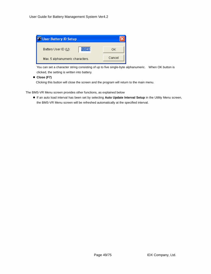
Battery Setup (F4)
This option is highlighted when a supported battery is connected to the channel. A user selected
name or ID can be stored in the battery. The Battery User ID provides a simple means for
identifying each battery.
When this button clicked, The following dialogs are displayed
User Guide for Battery Management System Ver4.2
Page 49/75 IDX Company, Ltd.
You can set a character string consisting of up to five single-byte alphanumeric. When OK button is
clicked, the setting is written into battery.
Close (F7)
Clicking this button will close the screen and the program will return to the main menu.
The BMS-VR Menu screen provides other functions, as explained below
If an auto load interval has been set by selecting Auto Update Interval Setup in the Utility Menu screen,
the BMS-VR Menu screen will be refreshed automatically at the specified interval.
User Guide for Battery Management System Ver4.2
Page 50/75 IDX Company, Ltd.
CHAPTER 11. Items and Functions Available on the
Diagnostic Screen
Two types of data—“battery data” and “discharge data”—can be obtained.
Battery data: Data recorded in a battery (discharge data not included.)
Discharge data: Discharge data hardware such as i-Trax charger recorded.
If the i-Trax charger is connected, selecting “ Date Update” from the i-Trax Charger Menu screen will display
discharge data if it has already been obtained ( if it is recorded in the hardware.) If the discharge data has not
already been obtained (recorded in the database), battery data will be displayed.
If “Data Update “ is opened from the BMS-VR Menu screen, you must manually select the data to be obtained
(battery data or discharge data).
BMS-VR
1. To obtain battery data ( when connected to BMS-VR): 1) Select “Battery data” in the Mode select list box.
2) Click Load.
3) The data in the battery will be read and displayed on the screen.
2. To obtain discharge data ( when connected to BMS-VR): 1) Select “Discharge data” in the Mode select list box.
2) Click Load.
3) The battery discharge data in the hardware will be read and displayed on the screen.
i-Trax Charger
※When an i-Trax Charger is connected, battery data or discharge data
recorded in the database is automatically selected and displayed. Selecting a
mode in the diagnostic screen is not necessary.
User Guide for Battery Management System Ver4.2
Page 51/75 IDX Company, Ltd.
3. Explanation of each item
1. Mode Select Select the data acquisition mode as either “Battery Data” or “Discharge
Data”
2. Load Button for loading data
3. Save Button for saving data to the database
4. Database Button for displaying the Database screen
5. Print Button for printing the data shown on the screen
6. Web Button for connecting to IDX’s website (http://www.idx.tv)
7. Close Clicking this button will close the Diagnostic screen and display the
previous screen
8. Battery Model Model of the battery (batteries that are not supported by the BMS are
indicated as “E-0”)
9. Ser.No Serial number of the battery
10. Lot.No Lot number of the battery
11. Battery User ID Optional value that can be recorded in the battery. See page 58 for
details on the setting procedure
12. Number of Cycles Number of charge cycle
13. Nominal Capacity Nominal capacity of the battery
1
2
3
4
8
9
10
11
12
13
14
15
16
18
17
19 20
21
22
24
25 26
A
B
C
D
E
F
G
5 6 7
23
27 28
User Guide for Battery Management System Ver4.2
Page 52/75 IDX Company, Ltd.
14. Date of First Full Charge Date of the first full charge
15. Discharge Record Record of the last three discharges (date of discharge, maximum
discharge load, discharge time, maximum temperature)
16. Charge Record Record of the last three charges (date of charge, maximum charge
current, charge time, maximum temperature). Because the date of the
first full charge is shown in Date of First Full Charge, it is not included
in this data.
17. No. of Over Discharges Number of over-discharges (date of over-discharge, minimum voltage).
This data is recorded when the voltage of a single cell has dropped to
2.3 V or below. Therefore, depending on the deterioration condition of
a given cell this data may be recorded even when the overall voltage of
the battery pack is 9.2 V or above.
18. No. of High Loads Number of times the battery was used at a high load (date of use,
discharge load, voltage, maximum current, temperature). This data is
recorded when the power output at the maximum load current is 50 W
or above.
19. Lowest Temp. The battery’s lowest operating temperature and the date on which it
was recorded
20. Highest Temp. The battery’s highest operating temperature and the date on which it
was recorded
21. Adaptor Name Name of the hardware device in use at time of data load
22. Adaptor Ver. Version of the hardware device in use at time of data load
23. Data From Display where the data is read from.
Database: read from database
File: read from files
Channel names: read from i-Trax charger
USB-n : read from BMS-VR
24. Graph Image Graphical representation of the discharge curve (change in voltage as
a function of time).
25. Datebox Button for switching on/off the items in the Databox (items A to G).
26. Time(min) Voltage(V) Time and voltage corresponding to the position of the mouse pointer in
the graph.
27. Initial Save Save displayed graph image as a first data.
28. Initial Graph Graph data saved from the initial save is displayed with the current
graph by arranging them together.
A. User Ref. You can enter and display a desired management number for the data
obtained (using up to 20 single-byte alphanumeric).
B. Battery Model Model of the battery. Users may also enter a desired model code for
those batteries that are not supported by the BMS (using up to 12
single-byte alphanumeric).
C. Ser. No Serial number of the battery
User Guide for Battery Management System Ver4.2
Page 53/75 IDX Company, Ltd.
D. Date Tested Date of discharge or date of data obtained
E. Average Load Average discharge load (unit: Watt) of the data obtained
F. Time Discharge duration (unit: min.) of the data obtained
G. Capacity Discharge capacity (unit: Wh) and its level indicated by a percentage
of the nominal capacity
* The BMS uses dates based on Greenwich Mean Time (Coordinated Universal Time). Certain conditions or
environments may cause errors of approx. 5% between GMT and the capacities or times shown by the
BMS.
User Guide for Battery Management System Ver4.2
Page 54/75 IDX Company, Ltd.
4. Example
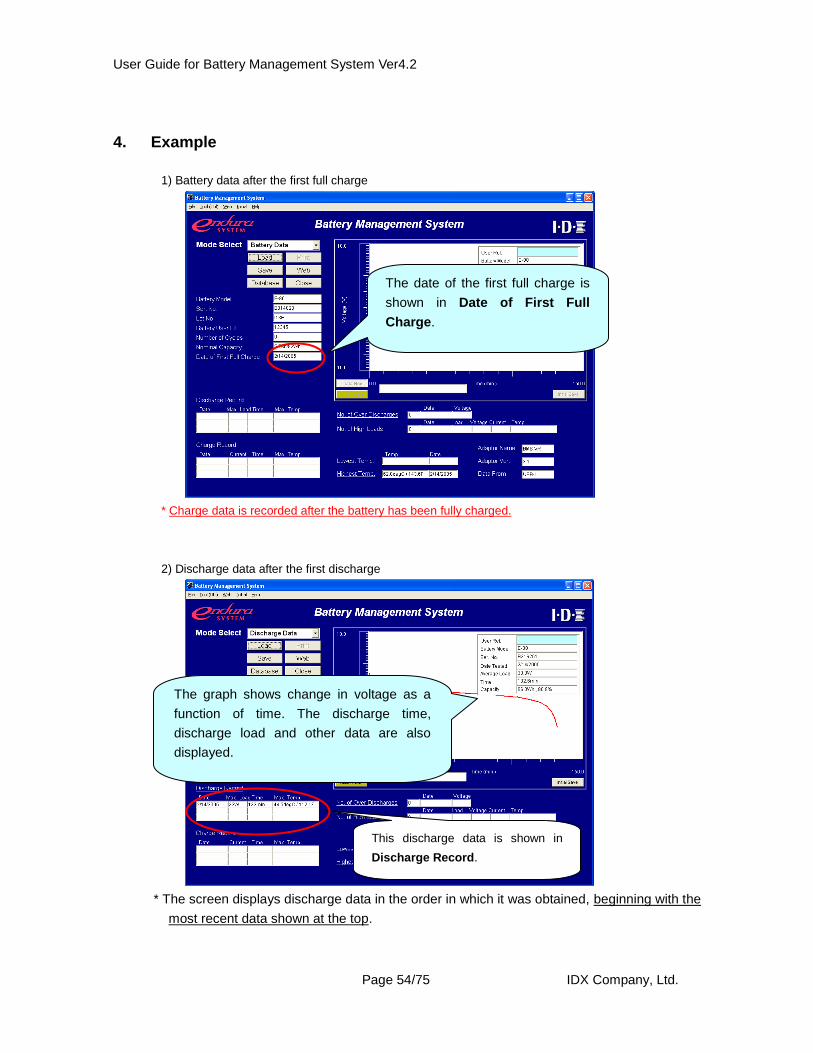
1) Battery data after the first full charge
* Charge data is recorded after the battery has been fully charged.
2) Discharge data after the first discharge
* The screen displays discharge data in the order in which it was obtained, beginning with the
most recent data shown at the top.
The date of the first full charge is
shown in Date of First Full
Charge.
This discharge data is shown in
Discharge Record.
The graph shows change in voltage as a
function of time. The discharge time,
discharge load and other data are also
displayed.
User Guide for Battery Management System Ver4.2
Page 55/75 IDX Company, Ltd.
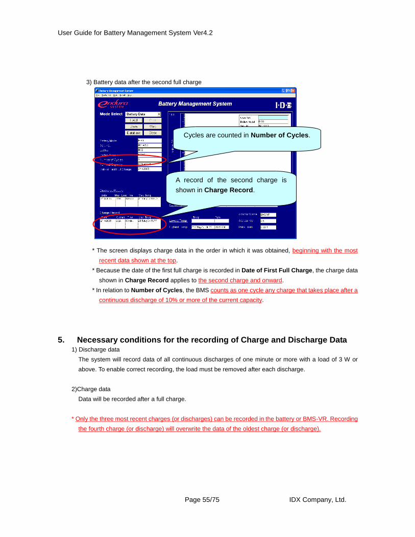
3) Battery data after the second full charge
* The screen displays charge data in the order in which it was obtained, beginning with the most
recent data shown at the top.
* Because the date of the first full charge is recorded in Date of First Full Charge, the charge data
shown in Charge Record applies to the second charge and onward.
* In relation to Number of Cycles, the BMS counts as one cycle any charge that takes place after a
continuous discharge of 10% or more of the current capacity.
5. Necessary conditions for the recording of Charge and Discharge Data 1) Discharge data
The system will record data of all continuous discharges of one minute or more with a load of 3 W or
above. To enable correct recording, the load must be removed after each discharge.
2)Charge data
Data will be recorded after a full charge.
* Only the three most recent charges (or discharges) can be recorded in the battery or BMS-VR. Recording
the fourth charge (or discharge) will overwrite the data of the oldest charge (or discharge).
A record of the second charge is
shown in Charge Record.
Cycles are counted in Number of Cycles.
User Guide for Battery Management System Ver4.2
Page 56/75 IDX Company, Ltd.
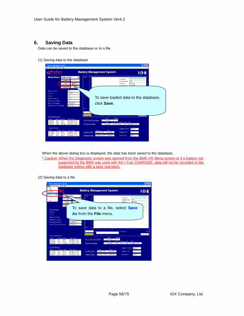
6. Saving Data Data can be saved to the database or to a file.
(1) Saving data to the database
When the above dialog box is displayed, the data has been saved to the database.
* Caution: When the Diagnostic screen was opened from the BMS-VR Menu screen or if a battery not supported by the BMS was used with the i-Trax CHARGER, data will not be recorded to the database unless with a save operation.
(2) Saving data to a file
To save loaded data to the database,
click Save.
To save data to a file, select Save
As from the File menu.
User Guide for Battery Management System Ver4.2
Page 57/75 IDX Company, Ltd.
On the above window, select the file destination, enter a file name, and then click Save. The data will be
saved.
The saved data can be accessed by
selecting Open from File
User Guide for Battery Management System Ver4.2
Page 58/75 IDX Company, Ltd.
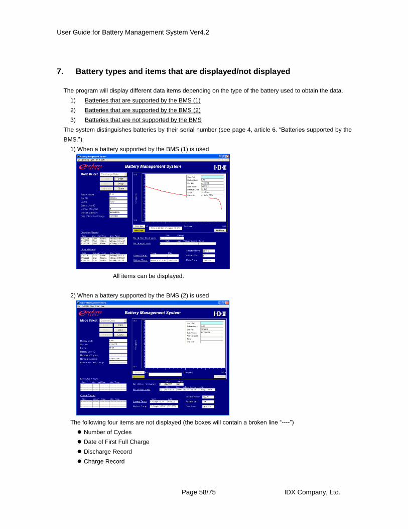
7. Battery types and items that are displayed/not displayed
The program will display different data items depending on the type of the battery used to obtain the data.
1) Batteries that are supported by the BMS (1)
2) Batteries that are supported by the BMS (2)
3) Batteries that are not supported by the BMS
The system distinguishes batteries by their serial number (see page 4, article 6. “Batteries supported by the
BMS.”).
1) When a battery supported by the BMS (1) is used
All items can be displayed.
2) When a battery supported by the BMS (2) is used
The following four items are not displayed (the boxes will contain a broken line “----”)
Number of Cycles
Date of First Full Charge
Discharge Record
Charge Record
User Guide for Battery Management System Ver4.2
Page 59/75 IDX Company, Ltd.
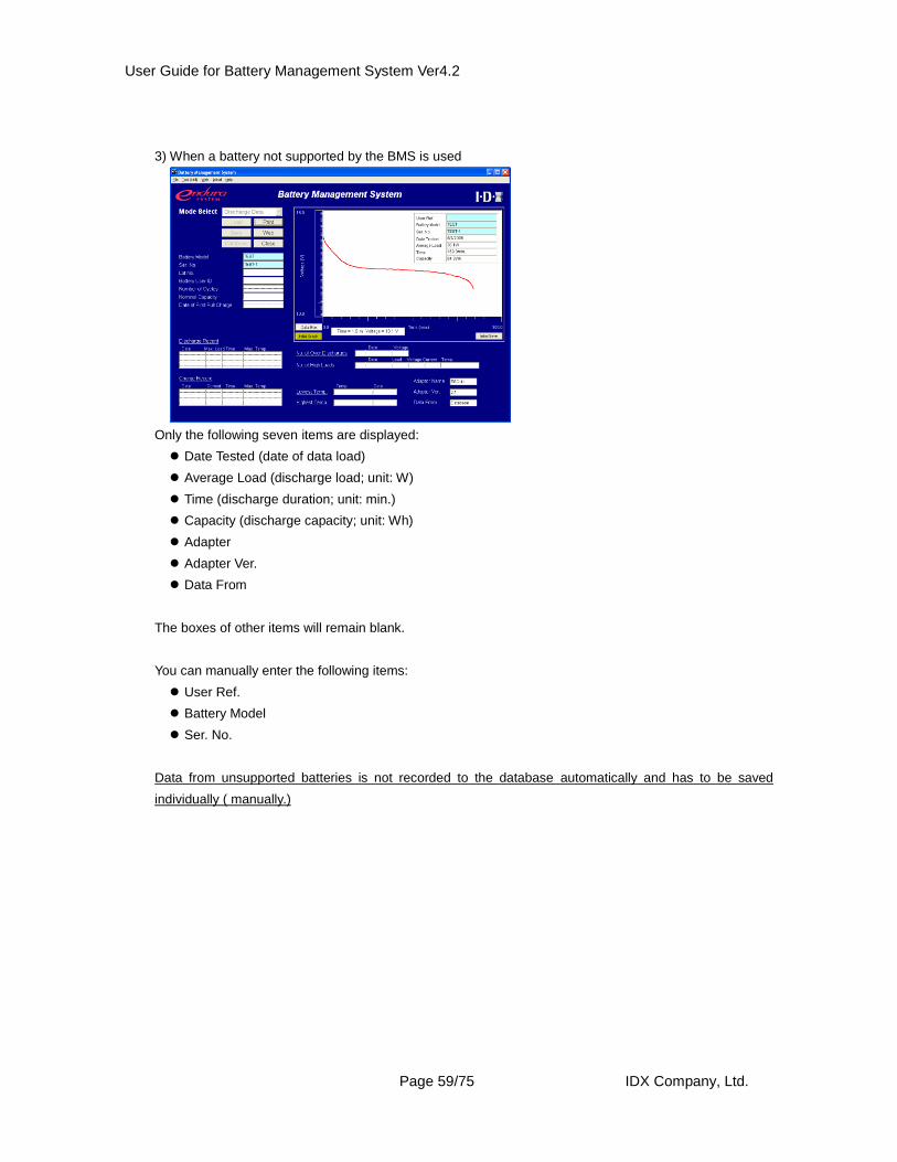
3) When a battery not supported by the BMS is used
Only the following seven items are displayed:
Date Tested (date of data load)
Average Load (discharge load; unit: W)
Time (discharge duration; unit: min.)
Capacity (discharge capacity; unit: Wh)
Adapter
Adapter Ver.
Data From
The boxes of other items will remain blank.
You can manually enter the following items:
User Ref.
Battery Model
Ser. No.
Data from unsupported batteries is not recorded to the database automatically and has to be saved
individually ( manually.)
User Guide for Battery Management System Ver4.2
Page 60/75 IDX Company, Ltd.
8. Explanation of the Menu Bar File
Open Opens saved data (in ipf format files).
Close Closes the file currently displayed.
Save Saves to the database data that has been displayed and edited.
Save IPF File Saves to a file data that has been displayed and edited.
Preview Shows how data that has been displayed and edited will appear on
a printed page.
Print Prints data that has been displayed and edited.
Exit Close the program.
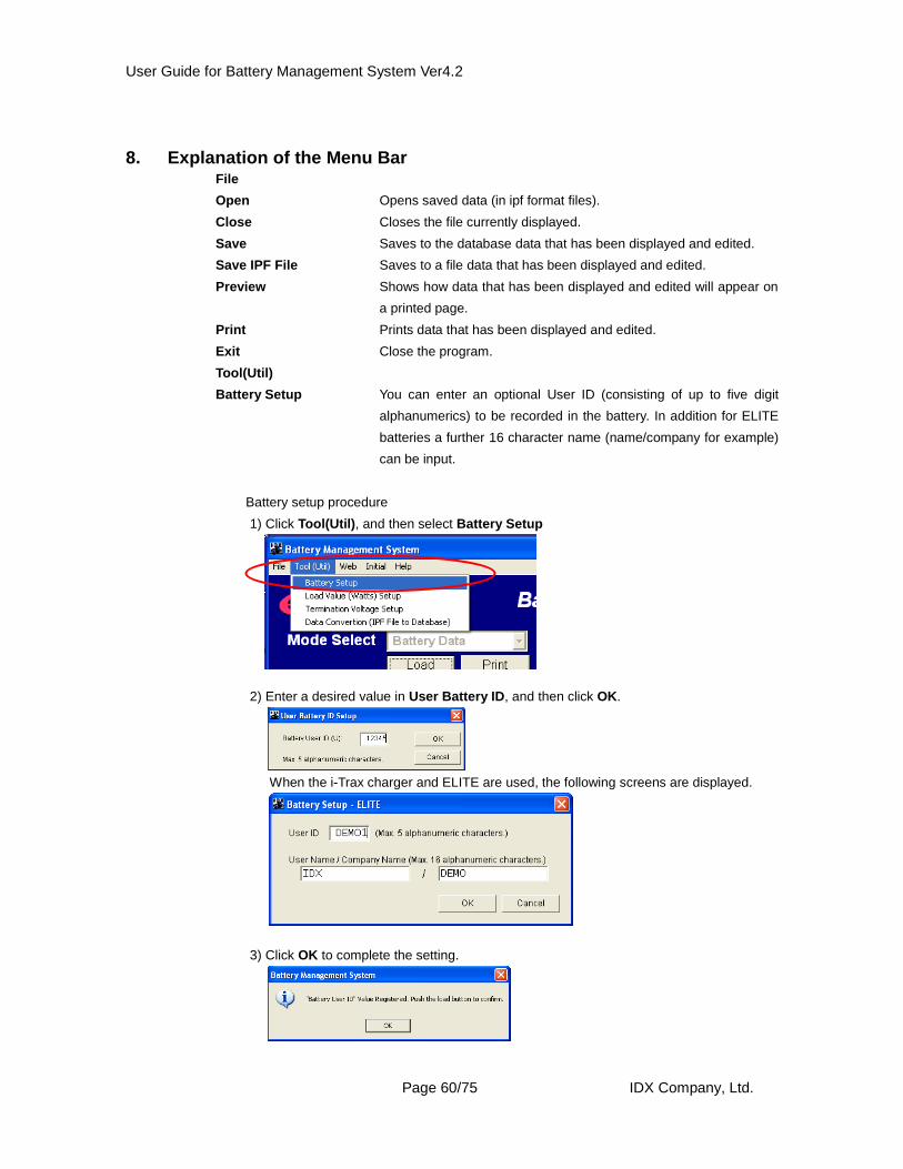
Tool(Util)
Battery Setup You can enter an optional User ID (consisting of up to five digit
alphanumerics) to be recorded in the battery. In addition for ELITE
batteries a further 16 character name (name/company for example)
can be input.
Battery setup procedure
1) Click Tool(Util), and then select Battery Setup
2) Enter a desired value in User Battery ID, and then click OK.
When the i-Trax charger and ELITE are used, the following screens are displayed.
3) Click OK to complete the setting.
User Guide for Battery Management System Ver4.2
Page 61/75 IDX Company, Ltd.
Load Value(Watts) Setup You can set discharge loads (unit: W) for the hardware.
Refer to CHAPTER 14, “Setting Up BMS-VR” for details
on the setting procedure.
Termination Voltage Setup You can set termination voltages (unit: V) for the
ESC-4i/VAL-4Si/BMS-VR. Refer to CHAPTER 14,
“Setting Up BMS-VR” for details on the setting procedure.
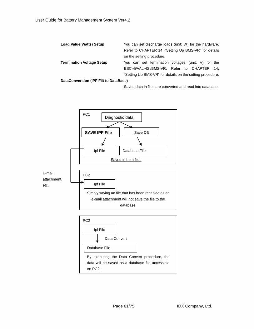
DataConversion (IPF Filt to DataBase)
Saved data in files are converted and read into database.
PC1 Diagnostic data
Ipf File Database File
SAVE IPF File
Saved in both files
PC2
Ipf File
Simply saving an file that has been received as an
e-mail attachment will not save the file to the
database.
E-mail
attachment,
etc.
PC2
Ipf File
Database File
Data Convert
By executing the Data Convert procedure, the
data will be saved as a database file accessible
on PC2.
Save DB
User Guide for Battery Management System Ver4.2
Page 62/75 IDX Company, Ltd.
Data Convert ( IPF to Database )Procedure
1) Click Tool(Util), and then select Data Conversion.
2) Specify the folder in which ipf files are saved, and then click OK.
3) Click Yes.
4) Click OK to complete the data conversion.
Web
IDX Web Site Connects to IDX’s website (http://www.idx.tv).
Initial
Database Folder Setup Displays the location where database files are saved
(changeable).
Printer Setup Specify the size of paper to which data will be printed
when the Print button is clicked (A4 or letter size).
Help
Version Displays the version of the BMS being used.
User Guide for Battery Management System Ver4.2
Page 63/75 IDX Company, Ltd.
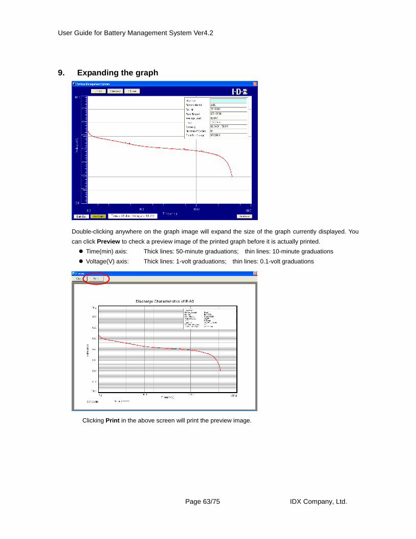
9. Expanding the graph
Double-clicking anywhere on the graph image will expand the size of the graph currently displayed. You
can click Preview to check a preview image of the printed graph before it is actually printed.
Clicking Print in the above screen will print the preview image.
User Guide for Battery Management System Ver4.2
Page 64/75 IDX Company, Ltd.
CHAPTER 12. Items and Functions Available on the
Database Screen
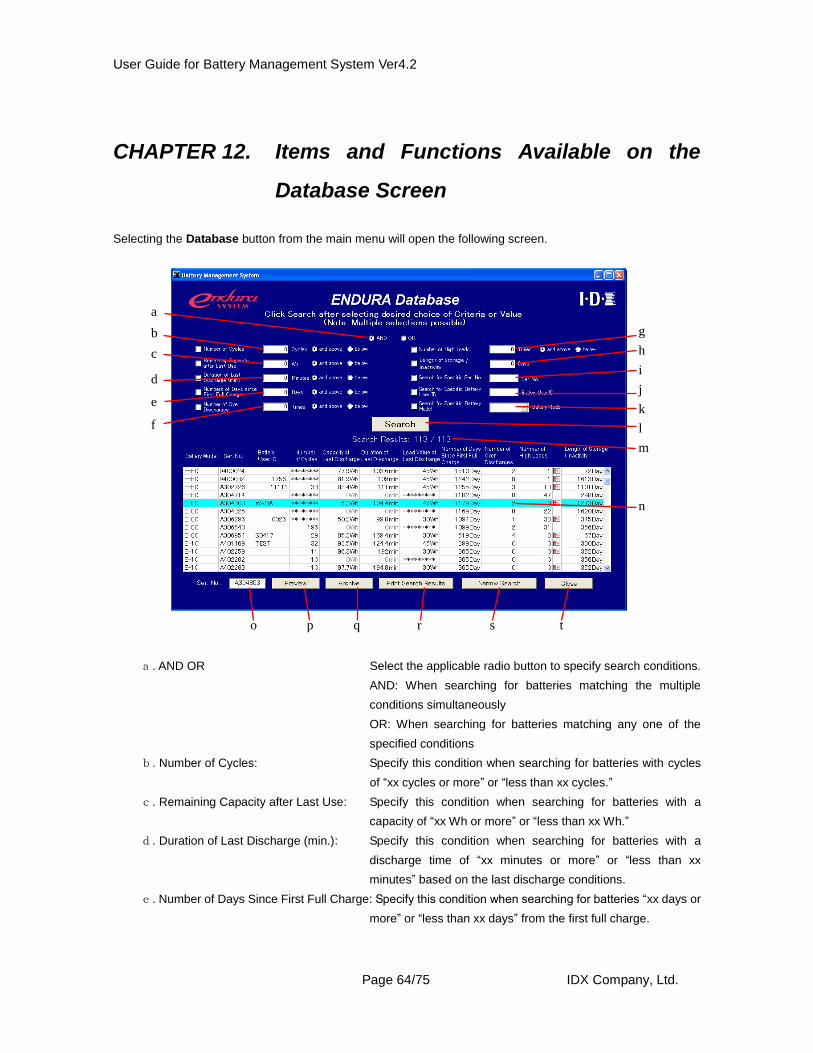
Selecting the Database button from the main menu will open the following screen.
a. AND OR Select the applicable radio button to specify search conditions.
AND: When searching for batteries matching the multiple
conditions simultaneously
OR: When searching for batteries matching any one of the
specified conditions
b. Number of Cycles: Specify this condition when searching for batteries with cycles
of “xx cycles or more” or “less than xx cycles.”
c. Remaining Capacity after Last Use: Specify this condition when searching for batteries with a
capacity of “xx Wh or more” or “less than xx Wh.”
d. Duration of Last Discharge (min.): Specify this condition when searching for batteries with a
discharge time of “xx minutes or more” or “less than xx
minutes” based on the last discharge conditions.
e. Number of Days Since First Full Charge: Specify this condition when searching for batteries “xx days or
more” or “less than xx days” from the first full charge.
a
b
c
d
e
f
g
h
i
j
k
l
n
o p q r
m
s t
User Guide for Battery Management System Ver4.2
Page 65/75 IDX Company, Ltd.
f. Number of Over Discharges: Specify this condition when searching for batteries that have
been over-discharged “xx times or more” or “less than xx
times.”
g. Number of High Load: Specify this condition when searching for batteries that have
been used with high loads “xx times or more” or “less than xx
times.”
h. Length of Storage/Inactivity: Specify this condition when searching for batteries that have
neither been charged nor discharged “xx days or more” from
the last use.
i. Search for Specific Ser. No.: Specify this condition when searching for batteries by serial
number. (This condition cannot be used with other search
conditions.)
j. Search for specific Battery User ID: Specify this condition when searching for batteries by user
battery ID. (This condition cannot be used with other search
conditions.)
k. Search for Specific Battery Model: Specify this condition when searching for batteries by battery
model.
l. Search: Click this button to start search after search conditions a to k
have been selected.
m. Qualifying Batteries: After the Search button is clicked, the number of batteries
that match the selected conditions and the total number of
batteries recorded in the database will be displayed.
n.Results of Individual Searches: A list showing the number of batteries that matched each
search condition is displayed. You can click to select a desired
data field (the selected data field will change its color) and
check the usage record and latest diagnostic data of the
selected battery.
o. Ser. No.: The serial number of the battery selected from the search
results is displayed.
p. Preview: Clicking this button will open a screen showing the latest
diagnostic data of the selected battery.
q. Archive: Clicking this button will open a screen showing the usage
record of the selected battery
r. Print Search Result: Clicking this button will print the search result table.
s. Narrow Search: Display the warning value setting screen
t. Close: Clicking this button will close the DataBase screen
and the program will return to the Diagnostic screen.
User Guide for Battery Management System Ver4.2
Page 66/75 IDX Company, Ltd.
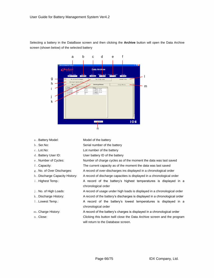
Selecting a battery in the DataBase screen and then clicking the Archive button will open the Data Archive
screen (shown below) of the selected battery
a. Battery Model: Model of the battery
b. Ser.No: Serial number of the battery
c. Lot.No: Lot number of the battery
d. Battery User ID: User battery ID of the battery
e. Number of Cycles: Number of charge cycles as of the moment the data was last saved
f. Capacity: The current capacity as of the moment the data was last saved
g. No. of Over Discharges: A record of over-discharges ins displayed in a chronological order
h. Discharge Capacity History: A record of discharge capacities is displayed in a chronological order
i. Highest Temp.: A record of the battery’s highest temperatures is displayed in a
chronological order
j. No. of High Loads: A record of usage under high loads is displayed in a chronological order
k. Discharge History: A record of the battery’s discharges is displayed in a chronological order
l. Lowest Temp.: A record of the battery’s lowest temperatures is displayed in a
chronological order
m. Charge History: A record of the battery’s charges is displayed in a chronological order
n. Close: Clicking this button twill close the Data Archive screen and the program
will return to the Database screen.
a b c d e f
g
i
k
l
m
n
h
j
User Guide for Battery Management System Ver4.2
Page 67/75 IDX Company, Ltd.
CHAPTER 13. Data Maintenance
The BMS offers the following data maintenance functions:
1.Deleting unnecessary battery data from the database
2.Optimizing database file
1. Deleting unnecessary Battery Data from the Database Use this function to delete from the database data on batteries that are no longer in use or have been
disposed of.
Operating procedure
1) Click Start, point to All Programs, point to Battery Management System, and then select
BMS_MAN.
2) On the Administration Menu screen, enter in single-byte characters the serial number of the battery
you want to delete, and then click Delete. Data of the selected battery will be deleted from the
database
User Guide for Battery Management System Ver4.2
Page 68/75 IDX Company, Ltd.
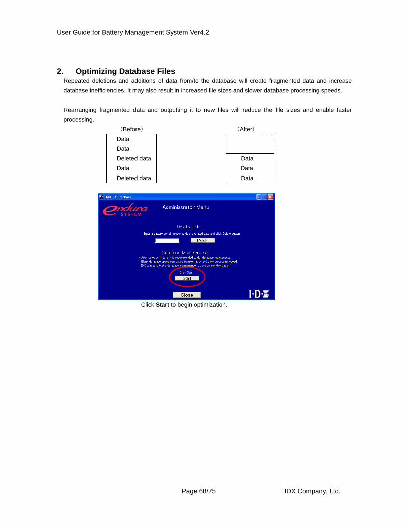
2. Optimizing Database Files Repeated deletions and additions of data from/to the database will create fragmented data and increase
database inefficiencies. It may also result in increased file sizes and slower database processing speeds.
Rearranging fragmented data and outputting it to new files will reduce the file sizes and enable faster
processing.
(Before) (After)
Data
Data
Deleted data Data
Data Data
Deleted data Data
Click Start to begin optimization.
User Guide for Battery Management System Ver4.2
Page 69/75 IDX Company, Ltd.
CHAPTER 14. Setting Up BMS-VR
The BMS lets you set up the following hardware:
BMS-VR: “Termination Voltages” and “Discharge Loads” can be set.
Settings can be entered directly by selecting the applicable ADJ. checkbox in the list on the i-Trax Charger
Menu or BMS-VR Menu screen, or they can also be specified in the Diagnostic screen. The latter method is
explained below.
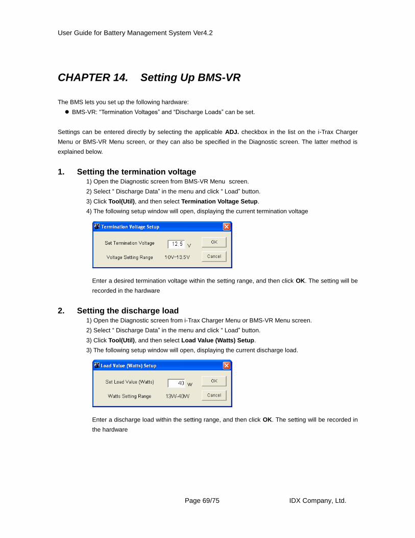
1. Setting the termination voltage 1) Open the Diagnostic screen from BMS-VR Menu screen.
2) Select “ Discharge Data” in the menu and click “ Load” button.
3) Click Tool(Util), and then select Termination Voltage Setup.
4) The following setup window will open, displaying the current termination voltage
Enter a desired termination voltage within the setting range, and then click OK. The setting will be
recorded in the hardware
2. Setting the discharge load 1) Open the Diagnostic screen from i-Trax Charger Menu or BMS-VR Menu screen.
2) Select “ Discharge Data” in the menu and click “ Load” button.
3) Click Tool(Util), and then select Load Value (Watts) Setup.
3) The following setup window will open, displaying the current discharge load.
Enter a discharge load within the setting range, and then click OK. The setting will be recorded in
the hardware
User Guide for Battery Management System Ver4.2
Page 70/75 IDX Company, Ltd.
CHAPTER 15. Utility Menu
Clicking the Utility button in the Main Menu screen will open the Utility Menu screen where you can set
various items.
Auto Update Interval Setup
Set the interval of automatic data load to the list on the i-Trax Charger Menu or BMS-VR Menu screen.
Saved Data Folder Setup
Set the folder to save database files in.
Print Setup
Specify the paper size to be used when printing data.
Close
Clicking this button will close this screen and the program will return to the Main Menu screen.
User Guide for Battery Management System Ver4.2
Page 71/75 IDX Company, Ltd.
1. Auto Update Interval Setup You can set the list on the i-Trax Charger Menu or BMS-VR Menu screen to be automatically refreshed at a
specified interval. Clicking Auto Update Interval Setup button will open the setup window.
When using auto load, select Auto Update, and then enter a desired interval in minutes. Then, click OK to
complete the setting. “ Manual Update “ is selected by default.
2. Saved Data Folder Setup Set the folder to save database files in. Normally, this folder has been specified automatically during the
installation and need not be set again. Use this function if you want to reference database files in a different
location.
Clicking Browse will open the file selection dialog box. Select a desired location of database files, and then click
OK to complete the setting.
3. Print Setup Specify the paper size to be used when printing data
Select “A4 size” or “Letter size” according to the printing paper used.
User Guide for Battery Management System Ver4.2
Page 72/75 IDX Company, Ltd.
CHAPTER 16. Frequently Asked Questions
1. Does the BMS operate on Macintosh computers?
A. No, the BMS is not designed to work with Macintosh computers.
2. How much hard disk space is required to save data?
A. Each Save IPF File command results in a storage of approximately 5 KB of data, which should pose no
problems for any PC currently on the market. (Reference: One floppy disk can save data from approximately
200 save operations.)
3. Can IDX help interpret what the loaded data is telling us about the condition of a battery?
A. When you execute the Save IP File command, the data is saved in an ipf file (a file name with an extension
of .ipf). Please send an e-mail to IDX with the saved file as an attachment, and we will be happy to provide
assistance. Refer to CHAPTER 18, “Contacting Us,” for e-mail addresses, etc.
4. When is a cycle counted?
A. Any recharge after a discharge of 10% or more of the current capacity is counted as one cycle.
5. How is an over-discharge recorded?
A. For E-50/E-7/E-80/E-10/E-HL9 : An over-discharge is recorded when the voltage of a single cell has
dropped to 2.3 V or below. Therefore, depending on the deterioration condition of a given cell this data may
be recorded even when the overall voltage of the battery pack is 9.2 V or above.
ELITE : An over-discharge is recorded when the voltage of battery reaches 12V or below.
6. How is a high load recorded?
A. E-50(Serial G023619-G023921,G024000-G024818): A high load is recorded when the maximum load
power is 35 W or above.
E-50(Other): A high load is recorded when the maximum load power is 50 W or above.
E-7: A high load is recorded when the maximum load power is 42 W or above.
E-80, E-10: A high load is recorded when the maximum load power is 50 W or above.
ELITE : A high load is recorded when the maximum load power is 115W or above.
E-HL9 : A high load is recorded when the maximum load power is 120W or above.
User Guide for Battery Management System Ver4.2
Page 73/75 IDX Company, Ltd.
CHAPTER 17. Explanations of Error Message
1. Data Communication Error (Read)
This error message is displayed when a communication error (read) has occurred while the BMS was
communicating with the hardware
2. Data Communication Error (Write)
This error message is displayed when a communication error (write) has occurred while the BMS was
communicating with the hardware.
3. Printer not installed
This error message is displayed when the printer driver has not been installed.
4. Mode is not selected
This error message is displayed when the user has not yet selected a data acquisition mode.
5. Cannot locate system Information
This error message is displayed when the computer cannot find software information.
6. Error reading file
This error message is displayed when an error has occurred while reading saved data.
7. Cannot find linked hardware
This error message is displayed when the hardware is not connected.
8. System cannot be accessed. Device is not ready
This error message is displayed when the floppy disk drive, CD-ROM drive or other device is not ready.
9. Error cannot find the file; IDXProf.dll (48)
This error message is displayed when there is no DLL file.
10. The selected file does not exist
This error message is displayed when the selected file cannot be found.
11. Battery User ID is not entered
This error message is displayed when a user battery ID has not been entered.
12. Communication error
This error message is displayed when the hardware is not or is incorrectly connected.
User Guide for Battery Management System Ver4.2
Page 74/75 IDX Company, Ltd.
13. Communication not possible per under discharge (80h)
This error message is displayed when communication is not possible because batteries are `being
charged or discharged.
14. There is not an appointed file
This error message is displayed when the specified file does not exist.
15. A file is not chosen
This error message is displayed when no file has been selected.
16. There is not an appointed file with a database file
This error message is displayed when the specified file is not a database file.
17. I choose file making being anonymous in the state that a database is not registered with
This error message is displayed when the user specified “not to create IPF files” when a location for
saving database files has not been registered.
18. There is not a folder
This error message is displayed when no folder exists.
19. There is not a pertinence file
This error message is displayed when no applicable file exists.
20. I failed in database connection
This error message is displayed when connection to the database has failed.
21. There is not a database file
This error message is displayed when no database file exists.
22. Chosen Value Out Of Range, Please Reset
This error message is displayed when the value that has been entered is outside the setting range.
* If any other error message is displayed, please contact IDX.
User Guide for Battery Management System Ver4.2
Page 75/75 IDX Company, Ltd.
CHAPTER 18. Contacting Us
Please direct all inquiries regarding this system to the following:
IDX Company, Ltd.
6-28-11 Shukugawara Tama-ku, Kawasaki-shi, Kanagawa, 214-0021 Japan


![CMPEN 472 Lecture Reference Materialkxc104/class/cmpen472/17s/lec/L02CMPEN472Lec… · imm dir ext rel idx idx idx idx idx idx idxi idx2 [idx2] [d,idx] ... 3905 3909 390b 390e 3910](https://static.documents.pub/doc/80x56/5aa3101d7f8b9a1f6d8e0e86/cmpen-472-lecture-reference-kxc104classcmpen47217slecl02cmpen472lecimm-dir.jpg)


