1st Internatio nal Elec tro nic Conference o n Actuato r Technology: Materials, Devices and Applic atio ns (IeCAT 2020) Conference Proceedings Paper Active Disturbance Rejection Control for Double Pump Direct Driven Hydraulics Shuzhong Zhang 1, *, Angen Wu 1 and Fuquan Dai 2 1 School of Mechanical and Automotive Engineering, Fujian University of Technology, Fuzhou, China; [email protected]; [email protected]2 Fujian Haiyuan Composite Materials Technology Co., Ltd. * Correspondence: [email protected]; Tel.: +86-591-228-63232 Abstract: As the energy crisis and further development of the electro-hydraulic actuator driven by servo motor, double-pump direct driven hydraulics (DDH) was brought forward, which mainly comprises of a servo motor, double fixed displacement pumps, a differential cylinder, a low- pressurized tank and auxiliary valves. To address the problems caused by uncertain parameters and unknown external disturbances of DDH, this paper proposed a control method adopting active disturbance rejection control (ADRC). Firstly, a mathematical model, including a DDH unit and a micro-crane, was created and modelled in MATLAB/Simulink. Further, the model was verified by measurement. After that, the state-space equation model of the system was derived based on its mathematical model and a third-order ADRC was designed using the constructed system state- space equation. Additionally, tracking-differentiator (TD) was employed to process the input signal transiently to avoid unnecessary oscillations, and the extended state observer (ESO) was used to accurately estimate the influence of the uncertainty and compensate by nonlinear feedback control law (NFCL). Moreover, the proposed ADRC or Proportional-Integral-Differential (PID) control was combined with the mathematical model of a micro-crane. Finally, the simulations were performed under varying loads, and the system position tracking performance were analyzed and compared. The results show that the ADRC can sufficiently suppress the unknown external disturbance, has the advantages of robustness and improves the position tracking precision. Keywords: Direct driven hydruics (DDH); Differential cylinder; Tracking-differentiator (TD); Extended state observer (ESO); Active disturbance rejection control (ADRC); Position control. 1. Introduction The electro-hydraulic servo system can be roughly divided into two categories: valve-controlled system and pump-controlled system. The valve-controlled system has the characteristics of fast dynamic response and high control accuracy, but it has disadvantages such as significantly throttling loss, low system efficiency, and severe heating. Compared with the valve-controlled system, the pump-controlled system basically eliminates the throttling loss. Hence, it significantly improves system efficiency and has the characteristics of compactness and high system integration [1, 2]. In recent years, machines have to be energy efficient due to limited and high-priced energy resources together with the increasing sensitivity of environmental issues [3, 4]. Hence, pump-controlled system techniques have become the centre of the focus [5, 6]. However, in the pump-controlled differential cylinder system, unbalanced flow caused by the unequal effective cross-section area of the two chambers. Many researches were carried out on it,
Transcript
1st International Electronic Conference on Actuator Technology: Materials, Devices and Applications (IeCAT 2020)
Conference Proceedings Paper
Active Disturbance Rejection Control for Double Pump Direct Driven Hydraulics
Shuzhong Zhang 1,*, Angen Wu 1 and Fuquan Dai 2
1 School of Mechanical and Automotive Engineering, Fujian University of Technology, Fuzhou, China;
Abstract: As the energy crisis and further development of the electro-hydraulic actuator driven by
servo motor, double-pump direct driven hydraulics (DDH) was brought forward, which mainly
comprises of a servo motor, double fixed displacement pumps, a differential cylinder, a low-
pressurized tank and auxiliary valves. To address the problems caused by uncertain parameters and
unknown external disturbances of DDH, this paper proposed a control method adopting active
disturbance rejection control (ADRC). Firstly, a mathematical model, including a DDH unit and a
micro-crane, was created and modelled in MATLAB/Simulink. Further, the model was verified by
measurement. After that, the state-space equation model of the system was derived based on its
mathematical model and a third-order ADRC was designed using the constructed system state-
space equation. Additionally, tracking-differentiator (TD) was employed to process the input signal
transiently to avoid unnecessary oscillations, and the extended state observer (ESO) was used to
accurately estimate the influence of the uncertainty and compensate by nonlinear feedback control
law (NFCL). Moreover, the proposed ADRC or Proportional-Integral-Differential (PID) control was
combined with the mathematical model of a micro-crane. Finally, the simulations were performed
under varying loads, and the system position tracking performance were analyzed and compared.
The results show that the ADRC can sufficiently suppress the unknown external disturbance, has
the advantages of robustness and improves the position tracking precision.
Keywords: Direct driven hydruics (DDH); Differential cylinder; Tracking-differentiator (TD);
Extended state observer (ESO); Active disturbance rejection control (ADRC); Position control.
1. Introduction
The electro-hydraulic servo system can be roughly divided into two categories: valve-controlled
system and pump-controlled system. The valve-controlled system has the characteristics of fast
dynamic response and high control accuracy, but it has disadvantages such as significantly throttling
loss, low system efficiency, and severe heating. Compared with the valve-controlled system, the
pump-controlled system basically eliminates the throttling loss. Hence, it significantly improves
system efficiency and has the characteristics of compactness and high system integration [1, 2]. In
recent years, machines have to be energy efficient due to limited and high-priced energy resources
together with the increasing sensitivity of environmental issues [3, 4]. Hence, pump-controlled
system techniques have become the centre of the focus [5, 6].
However, in the pump-controlled differential cylinder system, unbalanced flow caused by the
unequal effective cross-section area of the two chambers. Many researches were carried out on it,
1st International Electronic Conference on Actuator Technology: Materials, Devices and Applications (IeCAT 2020)
2
such as using pilot-operated check valve or solenoid-operated reversing valve [7, 8], developing
asymmetric flow distribution pump [9], proposing double-pump or multi-pump compensation
circuit [10-12] to solve flow imbalanced problem. Among them, the double-pump direct driven
hydraulic (DDH) system can better improve the dynamic performance and stability of the system.
Then, when addressing the problem of flow imbalance, the time-varying and nonlinearity of the
pump-controlled system also need to be solved. Hence, many control methods were proposed, such
as adaptive fuzzy control [13], control based on disturbance observer [14, 15], adaptive backstepping
control or iterative backstep control [16-18].
As discussed above, the DDH can effectively solve the problem of flow mismatch, but control
performance of the system is affected by parameter uncertainty. Therefore, this paper proposed a
control method adopting active disturbance rejection control (ADRC) for DDH. Firstly, Section 2
introduces the principle of the DDH and establishs the mathematical model of a micro-crane, and
derives the system state-space equation. Then, Section 3 gives the design procedure of the proposed
ADRC controller based on the system state-space. Section 4 performs simulation and compares the
tracking performance of the ADRC controller with Proportional-Integral-Differential (PID)
controller. Finally, Section 5 draws some conclusions.
2. Modelling
2.1 Working principle of DDH
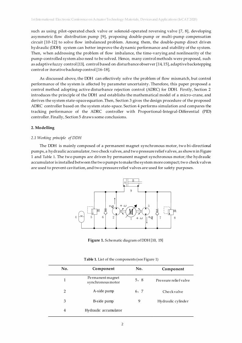
The DDH is mainly composed of a permanent magnet synchronous motor, two bi-directional
pumps, a hydraulic accumulator, two check valves, and two pressure relief valves, as shown in Figure
1 and Table 1. The two pumps are driven by permanent magnet synchronous motor; the hydraulic
accumulator is installed between the two pumps to make the system more compact; two check valves
are used to prevent cavitation, and two pressure relief valves are used for safety purposes.
M+ω
+ω +q
+q
12
3
4 5 87
9
6
AB
Figure 1. Schematic diagram of DDH [10, 19]
Table 1. List of the components (see Figure 1)
No. Component No. Component
1 Permanent magnet synchronous motor
5,8 Pressure relief valve
2 A-side pump 6,7 Check valve
3 B-side pump 9 Hydraulic cylinder
4 Hydraulic accumulator
1st International Electronic Conference on Actuator Technology: Materials, Devices and Applications (IeCAT 2020)
3
2.2 DDH Model
The DDH models mainly includes pump, cylinder. In the model, the following assumptions are
given: the hydraulic cylinder leakage is zero; the hydraulic cylinder load is an inertial load, and there
is no elastic load.
2.2.1. Pump model
The flow equation of the pump is given by:
A pAQ D (1)
B pBQ D (2)
where 𝜂 is the volumetric efficiency of the pump, and it is set to be 85%; 𝜔 is the angular velocity,
𝐷p is the volumetric displacement.
2.2.2 Cylinder model
The flow equation of the hydraulic cylinder can be expressed by:
1A A
Ae
Vq A x p
(3)
2B B B
e
Vq A x p
(4)
1 10 A
V V A x (5)
2 20 B
V V A x (6)
whree 𝑞𝐴 and 𝑞B are the flow of the chamber A and chamber B, 𝐴A is the piston area, 𝐴B is the
difference of piston and piston rod area, x is the absolute position of the piston 𝑝A and 𝑝B are the
pressure pressure of the chamber A and chamber B, 𝛽e is the effective bulk modulus, 𝑉1 and 𝑉2 is
the total volume of the chamber A and chamber B, 𝑉10 and 𝑉20 are”dead volume” of chamber A and
chamber B.
Hydraulic cylinder force balance equation can be expressed by:
1 2 cA BMx B x Fp pA A (7)
where 𝐵c is damping coefficient, 𝐹 is the random external load force.
2.2.3 State-space equation
Defining the state variables 1 2 3[ , , ] [ , , ]x x x x x x , according to the above equations A pA
Q D
(1)- 1 2 cA BMx B x Fp pA A (7), the system state-space equations can be represented as:
1 2
2 3
3 1 2 2 3 3
x x
x x
x k x k x k f
(8)
where
2 21 1 pA e 2 pB ee 2 e c L
1 2 3
1 2 1 2
( ); ; ;A D A DA A B F
k k k fV m V m m V m V m m
.
1st International Electronic Conference on Actuator Technology: Materials, Devices and Applications (IeCAT 2020)
4
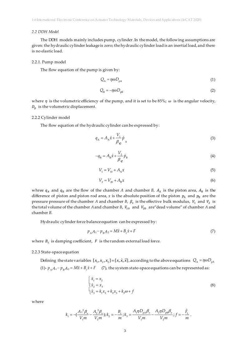
2.2.4 Mechanical model of the micro-crane
The schematic diagram of the crane structure is shown in Figure 2.
Figure 2. Crane structure diagram [10]
The load force acts on the end of the crane structure and generates torque around the joint Θ.
The torque balance equation is displayed as follows:
2
θ 2
dM J
dt (9)
2
1 1 m1 2 2 m2 load mload Cyl 12
1( ) ( . .sin( ) . .sin( ) .sin( )) .sin( ).
dm r m r m g F d
Jdt (10)
where 𝐹Cyl is the net hydraulic force, g is the gravitational constant, α is the angle between the
cylinder and the boom, 𝑚i is a mass, 𝑑1 and 𝑑2 are the distance to the upper fastening point of the
cylinder, 𝜃i are the angles between the centre of mass and the vertical axis.
The angles γ, 𝜃m1 , 𝜃m2 ,and 𝜃mload shown in Figure 2 can be determined by adding the change
of θ to the measured value when the hydraulic cylinder is fully retracted:
t
0 0
ddt
dt (11)
t
m1 m10 0
ddt
dt (12)
t
m2 m20 0
ddt
dt (13)
t
mload mload0 0
ddt
dt (14)
Use the sine rule given below to get the angle 𝛼:
2
t
sin( ) sin( )d
x (15)
where 𝑑2 is the distance to the fastening point on the cylinder, and 𝑥 t is the length of the cylinder plus
the stroke of the piston. 𝑥 t is derived using the cosine rule:
2 2 2
t 1 2 1 22 cos( )x d d d d (16)
1st International Electronic Conference on Actuator Technology: Materials, Devices and Applications (IeCAT 2020)
5
According to the derivation of equation 2 2 2
t 1 2 1 22 cos( )x d d d d
(16), the hydraulic
cylinder velocity can be expressed by:
1 2t
2 2
1 2 1 2
sin( )
2 cos( )
dd ddx dt
dt d d d d (17)
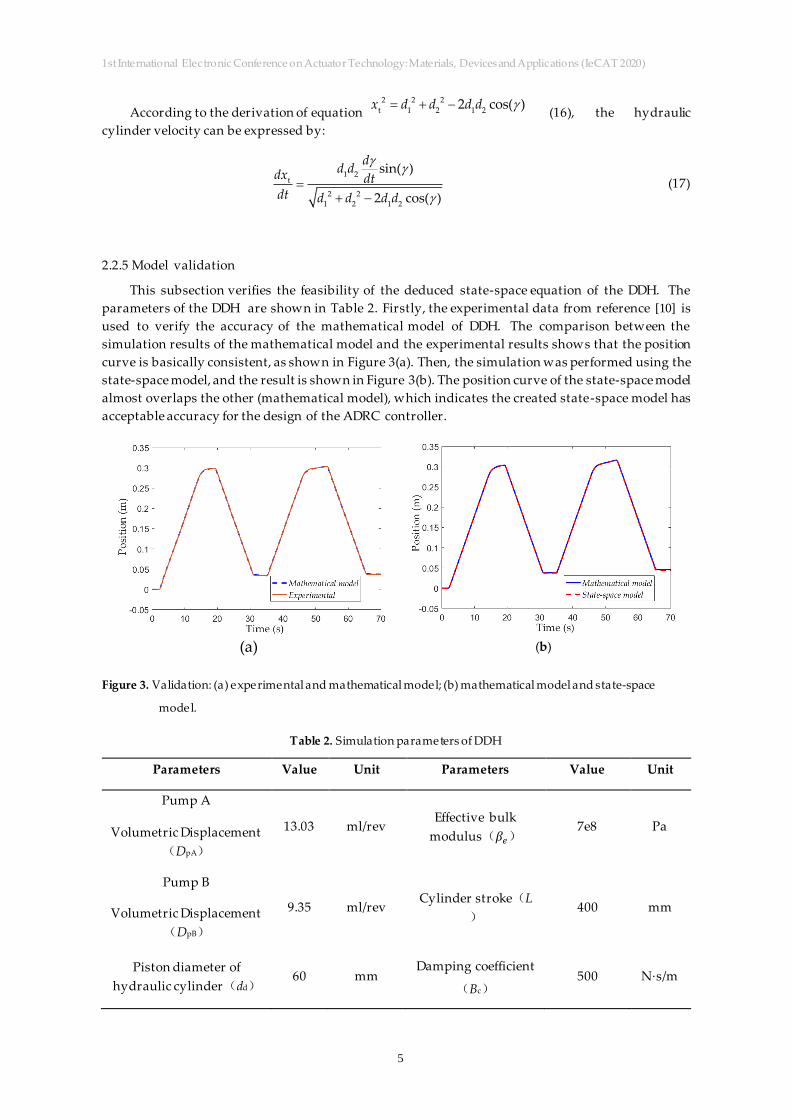
2.2.5 Model validation
This subsection verifies the feasibility of the deduced state-space equation of the DDH. The
parameters of the DDH are shown in Table 2. Firstly, the experimental data from reference [10] is
used to verify the accuracy of the mathematical model of DDH. The comparison between the
simulation results of the mathematical model and the experimental results shows that the position
curve is basically consistent, as shown in Figure 3(a). Then, the simulation was performed using the
state-space model, and the result is shown in Figure 3(b). The position curve of the state-space model
almost overlaps the other (mathematical model), which indicates the created state-space model has
acceptable accuracy for the design of the ADRC controller.
(a)
(b)
Figure 3. Validation: (a) experimental and mathematical model; (b) mathematical model and state-space
model.
Table 2. Simulation parameters of DDH
Parameters Value Unit Parameters Value Unit
Pump A
Volumetric Displacement
(DpA)
13.03 ml/rev Effective bulk
modulus(𝛽𝑒) 7e8 Pa
Pump B
Volumetric Displacement
(DpB)
9.35 ml/rev Cylinder stroke(L
) 400 mm
Piston diameter of
hydraulic cylinder(dd) 60 mm
Damping coefficient
(Bc) 500 N·s/m
1st International Electronic Conference on Actuator Technology: Materials, Devices and Applications (IeCAT 2020)
6
Piston rod diameter of
hydraulic cylinder(dr) 30 mm
Dead volume of
chamber A (V01) 2e-6 m3
Load mass(m) 50 kg Dead volume of
chamber B (V02) 2e-6 m3
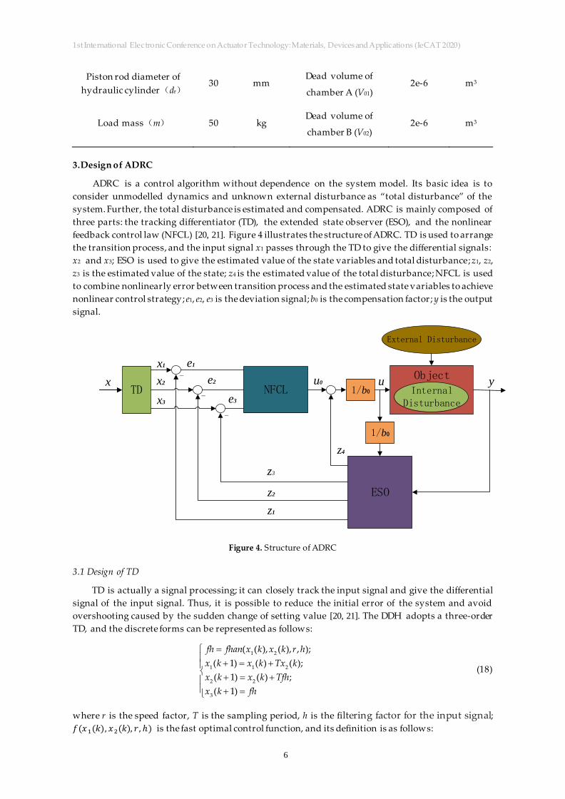
3.Design of ADRC
ADRC is a control algorithm without dependence on the system model. Its basic idea is to
consider unmodelled dynamics and unknown external disturbance as “total disturbance” of the
system. Further, the total disturbance is estimated and compensated. ADRC is mainly composed of
three parts: the tracking differentiator (TD), the extended state observer (ESO), and the nonlinear
feedback control law (NFCL) [20, 21]. Figure 4 illustrates the structure of ADRC. TD is used to arrange
the transition process, and the input signal x1 passes through the TD to give the differential signals:
x2 and x3; ESO is used to give the estimated value of the state variables and total disturbance; z1, z2,
z3 is the estimated value of the state; z4 is the estimated value of the total disturbance; NFCL is used
to combine nonlinearly error between transition process and the estimated state variables to achieve
nonlinear control strategy; e1, e2, e3 is the deviation signal; b0 is the compensation factor; y is the output
signal.
TDx
NFCL 1/b0
Object
External Disturbance
ESO
1/b0
x1
x2
x3 e3
e1
e2-
-
-
z1
z2
z4
z3
InternalDisturbance
u0 u y
Figure 4. Structure of ADRC
3.1 Design of TD
TD is actually a signal processing; it can closely track the input signal and give the differential
signal of the input signal. Thus, it is possible to reduce the initial error of the system and avoid
overshooting caused by the sudden change of setting value [20, 21]. The DDH adopts a three-order
TD, and the discrete forms can be represented as follows:
1 2
1 1 2
2 2
3
( ( ), ( ), , );
( 1) ( ) ( );
( 1) ( ) ;
( 1)
fh fhan x k x k r h
x k x k Tx k
x k x k Tfh
x k fh
(18)
where r is the speed factor, T is the sampling period, h is the filtering factor for the input signal;
𝑓(𝑥1(𝑘), 𝑥2(𝑘), 𝑟, ℎ) is the fast optimal control function, and its definition is as follows:
1st International Electronic Conference on Actuator Technology: Materials, Devices and Applications (IeCAT 2020)
7
2
0 2
1 0
1
2 0 1
0 2
( , ) ( ( ) ( )) / 2
( 8 )
( )( ) / 2
( ) ( , ) (1 ( , ))
( ) ( , ) ( )(1 ( , ))
fsg x d sign x d sign x d
d rh
a hx
y x a
a d d y
a a sign y a d
a a y fsg y d a fsg y d
afhan r fsg a d rsign a fsg a d
d
(19)
3.2 Design of ESO
The ESO is the core part of ADRC, which can track the state variables and estimate the internal
and external disturbance of the system without the need for any precise mathematical model. The
DDH uses a four-order ESO.
Let 𝑚n、𝐵cn、𝛽en be the nominal values of 𝑚、𝐵c、𝛽e respectively, and then can be expressed
by:
2 2
1 en 2 en1n
1 n 2 n
( )A A
kV m V m
(20)
cn2n
n
Bk
m (21)
1 pA en 2 pB en
3n
1 n 2 n
A D A Dk
V m V m
(22)
L
n
Ff
m (23)
Let 𝑎 be the difference between the nominal value and the actual value of the parameter, �� =
𝑘𝑛 − 𝑘, then equation 1 2
2 3
3 1 2 2 3 3
x x
x x
x k x k x k f
(8) can be rewritten as
1 2
2 3
3 1n 2 2n 3 3n
x x
x x
x k x k x k
(24)
where σ = ��1𝑥2 − ��2𝑥3 − ��3𝜔 + 𝑓 represents the total disturbance of the system; in order to estimate
the total disturbance, defining 4x as an extended state variable of the system, and assuming that
σ is differentiable, the system can be expressed by:
1 2
2 3
3 1n 2 2n 3 4 3n
4( , )
x x
x x
x a x a x x a
x f x t
(25)
where 𝑓(𝑥, 𝑡) represents the change rate of σ.
1st International Electronic Conference on Actuator Technology: Materials, Devices and Applications (IeCAT 2020)
8
Let z = [��1, ��2 , ��3, ��4] be the estimated vector of state x, then the ESO is designed as:
)(
)(
18
1
1044
314
1
103432213
10232
10121
11
esignez
aesignezzazaz
ezz
ezz
yze
nnn
(26)
Observer gain is simplified according to the bandwidth concept from reference [22].
2 3 4
01 02 03 044 6 , 4 ,,
3.3 Design of NFCL
Using the fastest control synthesis function fhan to perform nonlinear combination of errors, the
algorithm can be expressed by:
1 1 1
2 2 2
3 3 3
0 1 1 2 2 3 3
40
0
( , , ) ( , , ) ( , , )
.
e x z
e x z
e v z
u fal e fal e fal e
zu u
b
(27)
4 Simulation results and analysis
This section combines the DDH model, the micro-crane mechanical model, and the designed
ADRC method into one model, uses sine signal and actual working position signal as inputs to the
system, compares the position tracking performance with P and PI controller. The simulation
parameters of DDH are shown in Table 2, and the parameters of the micro-crane are shown in Table
3.
Table 3. Micro-crane structure parameters
Parameters Value Unit
d1 0.983 m
m1 25.11 kg
m2 21.40 kg
mload 40 kg
r2 0.977 m
rload
θm10
θm20
1.674
0.1169
0.1572
m
rad
rad
1st International Electronic Conference on Actuator Technology: Materials, Devices and Applications (IeCAT 2020)
9
θmload 0.1775 rad
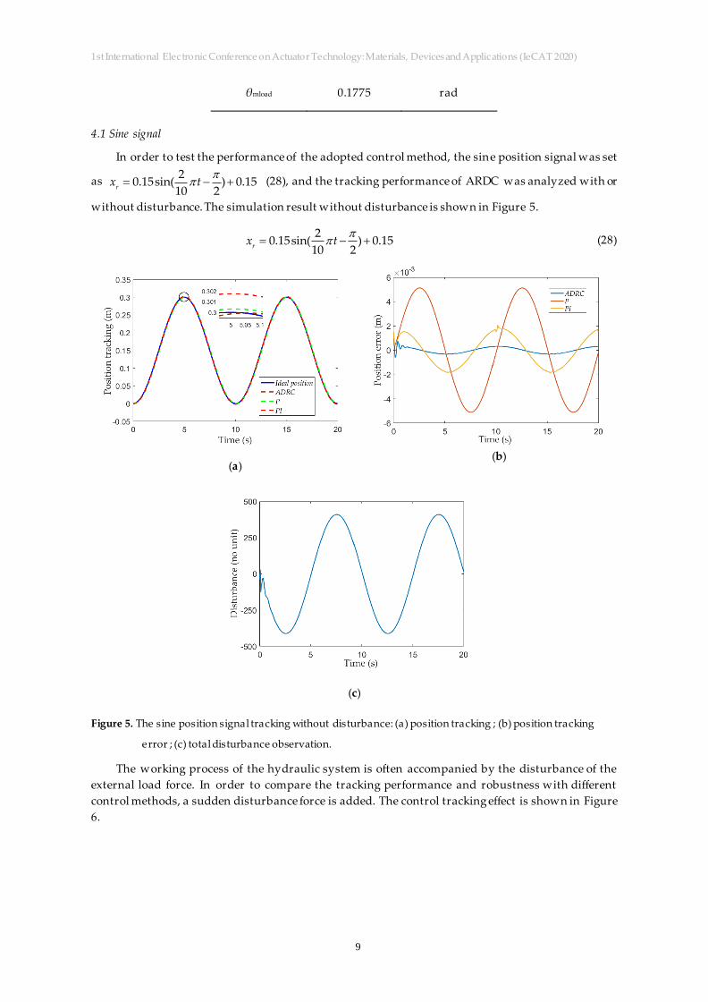
4.1 Sine signal
In order to test the performance of the adopted control method, the sine position signal was set
as
2
0.15sin( ) 0.1510 2r
x t (28), and the tracking performance of ARDC was analyzed with or
without disturbance. The simulation result without disturbance is shown in Figure 5.
2
0.15sin( ) 0.1510 2r
x t (28)
(a)
(b)
(c)
Figure 5. The sine position signal tracking without disturbance: (a) position tracking ; (b) position tracking
error ; (c) total disturbance observation.
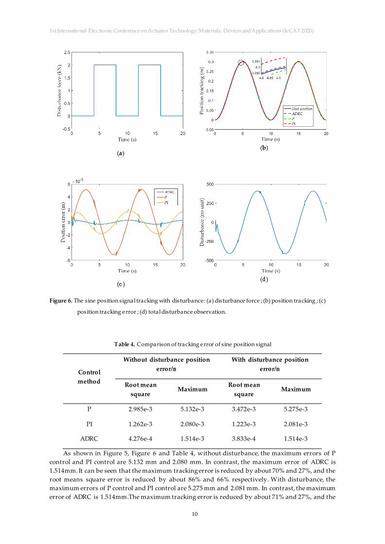
The working process of the hydraulic system is often accompanied by the disturbance of the
external load force. In order to compare the tracking performance and robustness with different
control methods, a sudden disturbance force is added. The control tracking effect is shown in Figure
6.
1st International Electronic Conference on Actuator Technology: Materials, Devices and Applications (IeCAT 2020)
10
(a)
(b)
(c )
(d )
Figure 6. The sine position signal tracking with disturbance: (a) disturbance force ; (b) position tracking ; (c)
position tracking error ; (d) total disturbance observation.
Table 4. Comparison of tracking error of sine position signal
Control
method
Without disturbance position
error/m With disturbance position
error/m
Root mean
square Maximum
Root mean
square Maximum
P 2.985e-3 5.132e-3 3.472e-3 5.275e-3
PI 1.262e-3 2.080e-3 1.223e-3 2.081e-3
ADRC 4.276e-4 1.514e-3 3.833e-4 1.514e-3
As shown in Figure 5, Figure 6 and Table 4, without disturbance, the maximum errors of P
control and PI control are 5.132 mm and 2.080 mm. In contrast, the maximum error of ADRC is
1.514mm. It can be seen that the maximum tracking error is reduced by about 70% and 27%, and the
root means square error is reduced by about 86% and 66% respectively. With disturbance, the
maximum errors of P control and PI control are 5.275 mm and 2.081 mm. In contrast, the maximum
error of ADRC is 1.514mm.The maximum tracking error is reduced by about 71% and 27%, and the
1st International Electronic Conference on Actuator Technology: Materials, Devices and Applications (IeCAT 2020)
11
root means square error is reduced by about 89% and 69% respectively. It can be seen that, with
ADRC, certain fluctuations appears at the begining, but it will converge quickly. The position
tracking error shown in Figure 5(b) and Figure 6(c) reveals that the ADRC suppresses internal and
external disturbances effectively, having high position tracking precision and strong robustness.
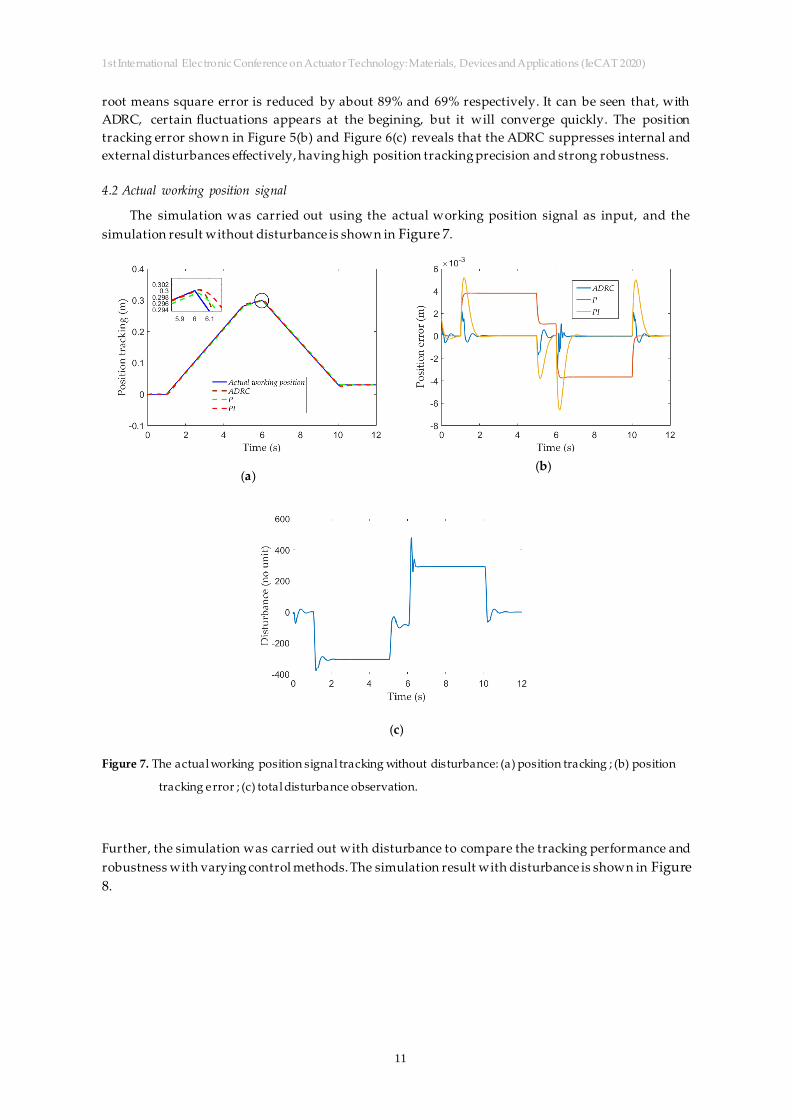
4.2 Actual working position signal
The simulation was carried out using the actual working position signal as input, and the
simulation result without disturbance is shown in Figure 7.
(a)
(b)
(c)
Figure 7. The actual working position signal tracking without disturbance: (a) position tracking ; (b) position
tracking error ; (c) total disturbance observation.
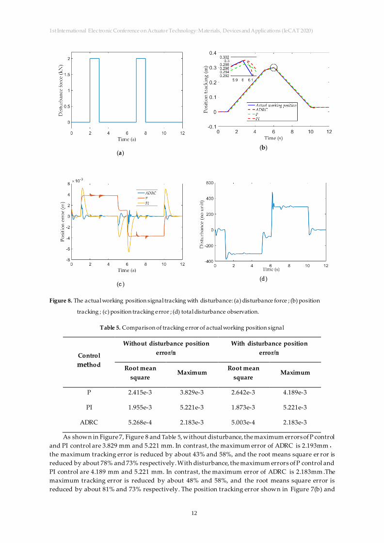
Further, the simulation was carried out with disturbance to compare the tracking performance and
robustness with varying control methods. The simulation result with disturbance is shown in Figure
8.
1st International Electronic Conference on Actuator Technology: Materials, Devices and Applications (IeCAT 2020)
12
(a)
(b)
(c )
(d )
Figure 8. The actual working position signal tracking with disturbance: (a) disturbance force ; (b) position
tracking ; (c) position tracking error ; (d) total disturbance observation.
Table 5. Comparison of tracking error of actual working position signal
Control
method
Without disturbance position
error/m With disturbance position
error/m
Root mean
square Maximum
Root mean
square Maximum
P 2.415e-3 3.829e-3 2.642e-3 4.189e-3
PI 1.955e-3 5.221e-3 1.873e-3 5.221e-3
ADRC 5.268e-4 2.183e-3 5.003e-4 2.183e-3
As shown in Figure 7, Figure 8 and Table 5, without disturbance, the maximum errors of P control
and PI control are 3.829 mm and 5.221 mm. In contrast, the maximum error of ADRC is 2.193mm,
the maximum tracking error is reduced by about 43% and 58%, and the root means square er ror is
reduced by about 78% and 73% respectively. With disturbance, the maximum errors of P control and
PI control are 4.189 mm and 5.221 mm. In contrast, the maximum error of ADRC is 2.183mm .The
maximum tracking error is reduced by about 48% and 58%, and the root means square error is
reduced by about 81% and 73% respectively. The position tracking error shown in Figure 7(b) and
1st International Electronic Conference on Actuator Technology: Materials, Devices and Applications (IeCAT 2020)
13
Figure 8(c) reveals that the ADRC suppresses internal and external disturbances effectively, having
high position tracking precision and strong robustness.
In summary, the simulation results shows the proposed ADRC control method has better
tracking performance and stronger robustness.
5 Conslusions
Aiming at the problems of uncertain parameters and unknown external disturbances in the
DDH, an ADRC controller was designed. The control method can estimate the total disturbance,
including parameter uncertainty and unknown disturbance, and make compensation. A model was
built, including the DDH, mechanism of the crane, and ADRC controller. Simulations were
performed using two types of reference signal. The simulation results reveal that, without
disturbance, compared with P and PI control, ADRC can reduce the maximum error by about 43%
and 58%, and can decrease the root means square error by about 78% and 73%. With disturbance,
compared with P and PI control, ADRC reduces the maximum error by about 48% and 58%, and
decrease the root means square error by about 81% and 73%. The results show that, compared with
PID control, ADRC can suppress internal and external disturbances effectively, has the advantages
of robustness and improves the position tracking precision.
Although the control method ADRC can improve control accuracy on the DDH based on the
simulation results, it should be compared with experimental data for validation . Hence, in the near
future, a test bench needs to be set up, and experiments should be performed with the proposed
control method.
Acknowledgments: This work was supported by the Science Foundation for Young Scholars of Fujian Province
(No.2018J05099), the Scie ntific Research Fund (No. GY-Z15096), Fujian Haiyuan Composite Materials
Technology Co., Ltd. and the Public Service Platform for Technical Innovation of Machine Tool Industry in Fujian University of Technology.
Author Contributions: Conceptualization, S.Z., and A.G.and F.D.; methodology, S.Z. and G.A.; software, G.A.;
investigation, S.Z. and G.A.; writing—original draft preparation, S.Z. and G.A.; writing—review and editing,
F.D.; supervision, S.Z.; project administration, F.D.; funding acquisition, F.D. All authors have read and agreed to the published version of the manuscript.
Conflicts of Interest: The authors declare no conflict of interest.
Abbreviations
The following abbreviations are used in this manuscript:
DDH : double-pump direct driven hydraulics
ARDC: Active disturbance re jection control
TD: Tracking-differentiator
ESO:Extended state observer
NFCL:Nonlinear feedback control law
References:
1. Quan, L. Current State,Problems and the Innovative Solution of Electro-hydraulic Technology of Pump
Controlled Cylinder. Chinese Journal of Mechanical Engineering 2008, 44, (11).
1st International Electronic Conference on Actuator Technology: Materials, Devices and Applications (IeCAT 2020)
14
2. Zhang, S.; Minav, T.; Pietola, M. Performance Comparison between Single a nd Double Pump Controlled
Asymmetric Cylinder under Four-quadrant Operation. Nongye Jixie Xuebao/Transactions of the Chinese
Society of Agricultural Machinery 2018, 49, (012), 409-419.
3. Fu, S.; Wang, L.; Lin, T. Control of electric drive powertrain based on variable speed control in construction
machinery. Automat Constr 2020, 119, 103281.
4. Lin, T.; Lin, Y.; Ren, H.; Chen, H.; Chen, Q.; Li, Z. Development and key technologies of pure electric
construction machinery. Renewable and Sustainable Energy Reviews 2020, 132, 110080.
5. Aliskan, H.; Balkan, T.; Platin, B.E. A Complete Analysis and a Novel Solution for Instability in Pump
Controlled Asymmetric Actuators. Journal of Dynamic Systems Measurement & Control 2015, 137, (9), 091008.
6. Quan, Z.; Quan, L.; Zhang, J. Review of energy efficient direct pump controlled cylinder electro -hydraulic