J. Fluid Mech. (2013), vol. 730, pp. 5–18. c Cambridge University Press 2013 5 doi:10.1017/jfm.2013.334 Three-dimensional instability of the flow around a rotating circular cylinder Jan O. Pralits 1, †, Flavio Giannetti 2 and Luca Brandt 3 1 DICCA, University of Genoa, Via Montallegro 1, 16145 Genoa (GE), Italy 2 DIIN, University of Salerno, Via Ponte don Melillo, 84084 Fisciano (SA), Italy 3 Linn´ e Flow Centre, KTH Mechanics, S-100 44 Stockholm, Sweden (Received 17 January 2013; revised 10 June 2013; accepted 22 June 2013) The two-dimensional stationary flow past a rotating cylinder is investigated for both two- and three-dimensional perturbations. The instability mechanisms are analysed using linear stability analysis and the complete neutral curve is presented. It is shown that the first bifurcation in the case of the rotating cylinder occurs for stationary three- dimensional perturbations, confirming recent experiments. Interestingly, the critical Reynolds number at high rotation rates is lower than that for the stationary circular cylinder. The spatial characteristics of the disturbance and a qualitative comparison with the results obtained for linear flows suggest that the stationary unstable three- dimensional mode could be of hyperbolic nature. Key words: vortex streets, wakes/jets 1. Introduction The flow past a circular cylinder often serves as a prototype to investigate the vortex formation and wake dynamics behind bluff bodies. In the case of a stationary cylinder the different bifurcations occurring when increasing the Reynolds number are well known. Here the Reynolds number is based on the dimensional free- stream velocity U ? ∞ , the cylinder diameter D ? and the kinematic viscosity ν ? . The steady two-dimensional symmetric flow becomes unstable above a critical value Re ≈ 47 (see Provansal, Mathis & Boyer 1987) via a Hopf bifurcation (see Noack & Eckelmann 1994) giving rise to a self-sustained structure usually termed K´ arm´ an vortex street. For values of Re above ≈190 the flow becomes unstable to three- dimensional perturbations, (see, e.g., Barkley & Henderson 1996; Williamson 1996). The rotating cylinder and corresponding bifurcations, on the other hand, have been studied primarily in the two-dimensional framework (see Kang, Choi & Lee 1999; Stojkovi´ c, Breuer & Durst 2002; Mittal & Kumar 2003; Stojkovi´ c et al. 2003; Pralits, Brandt & Giannetti 2010). A complete neutral curve for two-dimensional perturbations as a function of the rotation rate α and the Reynolds number is found in both Stojkovi´ c et al. (2003) and Pralits et al. (2010). The rotation rate is here defined as α = Ω D ? /(2U ? ∞ ) with Ω representing the cylinder angular velocity. In both investigations two different types of disturbances can be distinguished. The so-called mode I is similar (equal when α = 0) to the classical von K´ arm´ an instability. Unstable † Email address for correspondence: [email protected]
Three-dimensional instability of the flow arounda rotating circular cylinder
Jan O. Pralits1,†, Flavio Giannetti2 and Luca Brandt3
1DICCA, University of Genoa, Via Montallegro 1, 16145 Genoa (GE), Italy2DIIN, University of Salerno, Via Ponte don Melillo, 84084 Fisciano (SA), Italy
3Linne Flow Centre, KTH Mechanics, S-100 44 Stockholm, Sweden
(Received 17 January 2013; revised 10 June 2013; accepted 22 June 2013)
The two-dimensional stationary flow past a rotating cylinder is investigated for bothtwo- and three-dimensional perturbations. The instability mechanisms are analysedusing linear stability analysis and the complete neutral curve is presented. It is shownthat the first bifurcation in the case of the rotating cylinder occurs for stationary three-dimensional perturbations, confirming recent experiments. Interestingly, the criticalReynolds number at high rotation rates is lower than that for the stationary circularcylinder. The spatial characteristics of the disturbance and a qualitative comparisonwith the results obtained for linear flows suggest that the stationary unstable three-dimensional mode could be of hyperbolic nature.
Key words: vortex streets, wakes/jets
1. IntroductionThe flow past a circular cylinder often serves as a prototype to investigate the
vortex formation and wake dynamics behind bluff bodies. In the case of a stationarycylinder the different bifurcations occurring when increasing the Reynolds numberare well known. Here the Reynolds number is based on the dimensional free-stream velocity U?
∞, the cylinder diameter D? and the kinematic viscosity ν?. Thesteady two-dimensional symmetric flow becomes unstable above a critical valueRe ≈ 47 (see Provansal, Mathis & Boyer 1987) via a Hopf bifurcation (see Noack& Eckelmann 1994) giving rise to a self-sustained structure usually termed Karmanvortex street. For values of Re above ≈190 the flow becomes unstable to three-dimensional perturbations, (see, e.g., Barkley & Henderson 1996; Williamson 1996).The rotating cylinder and corresponding bifurcations, on the other hand, have beenstudied primarily in the two-dimensional framework (see Kang, Choi & Lee 1999;Stojkovic, Breuer & Durst 2002; Mittal & Kumar 2003; Stojkovic et al. 2003;Pralits, Brandt & Giannetti 2010). A complete neutral curve for two-dimensionalperturbations as a function of the rotation rate α and the Reynolds number is foundin both Stojkovic et al. (2003) and Pralits et al. (2010). The rotation rate is heredefined as α =ΩD?/(2U?
∞) with Ω representing the cylinder angular velocity. In bothinvestigations two different types of disturbances can be distinguished. The so-calledmode I is similar (equal when α = 0) to the classical von Karman instability. Unstable
solutions are found for Re > 47 and low rotation rates. As the Reynolds number isincreased the neutral curve of mode I is found for α(Re)→ 2. At higher rotationrates a second instability, denoted mode II, exists and has a frequency one order ofmagnitude lower than that of mode I. For a given Re it persists for a narrow rangeof rotation rates and the critical Reynolds number is slightly below the value of 50.In the vicinity of the upper neutral branch of mode II multiple stationary solutionswere found for a fixed Reynolds number (see Pralits et al. 2010). These solutionswere computed using arclength continuation and two turning points were found. Pralitset al. (2010) also presented the bifurcation diagram of two-dimensional instabilitiesfor the multiple solutions. In particular, it was shown that the second turning pointdetermines the rotation rate at which an unstable solution is last observed. In fact, thispoint defines the birth of a branch with stable steady-state solutions that continues atlarger α.
Pralits et al. (2010) conducted a structural sensitivity analysis using a combinationof direct and adjoint global modes in order to provide relevant knowledge about theorigin of the instability. In particular, the core region for the instability mechanism andthe sensitivity to steady variations of the underlying base flow were identified. Thestructural sensitivity of mode II has its maximum close to the stagnation point whilethe sensitivity with respect to the base flow was shown to have its maximum in thelow-rear part of the cylinder, in a region opposite to the stagnation point.
Experimental measurements of the flow past a rotating cylinder were performedby Barnes (2000) at low rotation rates to determine the value at which shedding issuppressed for Reynolds numbers between 50 and 65. The findings agrees with theresults of, e.g., Kang et al. (1999), Stojkovic et al. (2002) and Pralits et al. (2010)who showed that the vortex shedding behind a rotating cylinder disappears whenα is increased above the value of 2. To the best of the authors’ knowledge onlythe experimental work by Yildirim et al. (2008) reports a low-frequency sheddingat Re = 100 and α = 5.1. In an initial transient phase they observed a tilted vortexstructure in the wake of the cylinder and the measured frequency was similar to thecomputations by, e.g., Stojkovic et al. (2003) and Pralits et al. (2010). However, thevorticity core was located on the opposite side of the wake and their experimentcannot be considered a verification of the existence of mode II.
To the best of the authors’ knowledge, only few works have been concernedwith the three-dimensional stability characteristics of the rotating cylinder flow. Theinvestigation by ElAkoury et al. (2008) indicates that the cylinder rotation has astabilizing effect on three-dimensional perturbations thus increasing the Reynoldsnumber for two-dimensional/three-dimensional transition to values larger than thatobserved for the flow past a non-rotating cylinder. In the recent work by Rao et al.(2013) a detailed study regarding the transition from steady to unsteady flow is madealong with a mapping of the transition from two-dimensional to three-dimensionalflow. It is shown that vortex shedding is suppressed for α > 2.1 for all Reynoldsnumbers and that transition to three-dimensional flow occurs for Reynolds numberslightly below the value of 200. However, these authors did not investigate values ofthe rotation rate above 2.5.
It is known that when further increasing the rotation speed, the stagnation pointmoves away from the surface of the cylinder, and closed streamlines form, separatingthe flow internal and external to it. Within the internal flow, one can expect largepressure differences and Mittal (2004), who investigated the flow at α = 5 andRe = 200, argued that this will cause the appearance of three-dimensional centrifugalinstabilities, with spanwise scale λ≈ D.
Three-dimensional instability of the rotating cylinder flow 7
Further investigations are needed on the onset of a three-dimensional flow pasta rotating circular cylinder. In this work we therefore investigate the stabilitycharacteristics of three-dimensional perturbations superimposed on the stationary two-dimensional base flow using global stability analysis. Neutral curves, critical rotationrates and critical Reynolds numbers are presented in order to determine the onset ofthree-dimensional instabilities. The results are compared with the recent results in theDoctoral thesis by Linh (2011) where experiments of the flow past a rotating cylinderare presented, and a possible explanation is given for the difficulties of previousexperimental investigations (e.g. Yildirim et al. 2008) in detecting the low-frequencyvortex shedding at high rotation rates, the so-called mode II. A structural sensitivityanalysis is also conducted with the purpose of establishing the region responsible forthe generation of the instability. Finally, an indication regarding where to position apassive control device is shown based on a structural sensitivity analysis with respectto base-flow modifications.
In the following we will denote modes at rotation rates α < 2 as mode I and modesfor higher rotation rates, α > 2, as mode II. This is to be consistent with earlierinvestigations in which a similar notation has been used.
2. Linear stability analysis and numerical methodThe instability onset is studied using linear theory and a normal-mode analysis. The
flow quantities are decomposed in a steady part and a small unsteady perturbation as
U(x, y, t)= Ub(x, y)+ ε 1√2π
∫ ∞
−∞u(x, y, κ, t) exp(iκz) dκ, (2.1)
where the amplitude ε is assumed to be small and a Fourier transform is used toexpress the spanwise dependence of a general three-dimensional perturbation. Thesame decomposition is used for the pressure. The base flow Ub(x, y) satisfies thesteady Navier–Stokes equations for two-dimensional incompressible flow at a givenReynolds number Re and rotation rate α. The rotation of the cylinder is imposedas a boundary condition such that Ub · t = α and Ub · n = 0. Here t and n arethe tangential and normal versors to the cylinder surface. The dimensional free-stream velocity U?
∞ and diameter D? are used as reference velocity and lengthscales throughout the paper. Three-dimensional global modes are analysed assumingu(x, y, κ, t) = u(x, y, κ) exp(σ t) and p(x, y, κ, t) = p(x, y, κ) exp(σ t). Introducing thisdecomposition into the Navier–Stokes equations and collecting terms of order ε weobtain the linearized unsteady Navier–Stokes equations
σ u+ LκUb,Reu+∇κ p= 0, (2.2)
∇κ · u= 0. (2.3)
In the above expression ∇κ ≡ (∂x, ∂y, iκ) is the modified gradient operator and Lκdenotes the modified three-dimensional linearized Navier–Stokes operator. On thecylinder surface a no-slip boundary condition is imposed while in the far fieldappropriate radiative boundary conditions are used. For further details and notationsee Giannetti & Luchini (2007). The system (2.2)–(2.3) gives rise to a generalizedeigenvalue problem for the complex eigenvalue σ . For Re(σ ) < 0 the flow is stablewhile for Re(σ ) > 0 the mode is unstable and grows exponentially in time.
8 J. O. Pralits, F. Giannetti and L. Brandt
2.1. Numerical methodThe results presented here are obtained with the numerical code described in Giannetti& Luchini (2007). A second-order finite-difference approach is used to compute spatialderivatives of the governing partial differential equations together with an immersed-boundary technique to represent the cylinder surface on a Cartesian mesh. Thecomputational domain is rectangular. The steady nonlinear Navier–Stokes equationsare solved by Newton iteration in order to compute the base flow used for thelinear stability analysis. Arc-length continuation is adopted for rotation rates abovethe onset of the second mode where multiple steady state solutions exist. Further,the stability of the flow is investigated through the eigenvalue problem defined bythe linearized perturbation equations (2.2)–(2.3), where an implicitly restarted Arnoldialgorithm is implemented to compute the least stable eigenvalue and eigenmode. Themain results are obtained with a computational domain of length Lx = 50, Ly = 30 inthe streamwise x- and cross-stream y-direction, respectively. The cylinder is locatedsymmetrically between the upper and lower boundaries, 15 diameters downstream ofthe inflow. The Cartesian coordinate system has its origin in the centre of the cylinder(xc = 0, yc = 0). The computational mesh is non-uniform, see e.g. Giannetti & Luchini(2007), with a resolution of 400× 300 points in the x and y directions, respectively. Asquare domain measuring 2 × 2 diameters, with its centre coinciding with that of thecylinder, has a uniform mesh containing 100 grid points in each direction. The resultshave been validated by varying both resolution and domain size.
3. Stability characteristicsThe onset of three-dimensional instabilities is investigated by solving the linear
stability problem outlined in § 2 for different values of the Reynolds number, rotationrate and spanwise wavenumber. The growth rate σr and Strouhal number St = σi/(2π)of the least stable modes pertaining to the stationary base flows at Re = 100 and twodifferent rotation rates α = 4.75 and 5 are presented in figure 1 as a function of thespanwise wavenumber κ . In particular we focus on the two least stable modes and thereason will be discussed in this section.
When the spanwise wavenumber is small, the perturbation Strouhal number isnon-zero and the corresponding maximum growth rate is found for κ = 0, the so-called unsteady mode II. For increasing values of the spanwise wavenumber the leaststable solution is stationary. This is a novelty compared with previous investigationsconducted in a two-dimensional framework. At α = 5 the maximum growth rate ofthe stationary mode is about three times that of the unsteady mode. Moreover, theunstable stationary perturbation remains unstable for values of α where the unsteadyone is already stable (here α = 4.75). Finally, for intermediate values of κ thereexists a range of values of α where the unsteady and stationary modes are unstablesimultaneously (here α = 5 and κ ≈ 0.3). The results presented in figure 1 areexploited more in detail in figure 2 where the growth rate (σr > 0) of the least stablemode is presented as a function of α and κ at four different values of the Reynoldsnumber. One can first of all note that in all figures that the mode α = 0, κ = 0is the classical von Karman instability (appearing when Re > 47). Shedding modeI is reported for Re = 50, 60, 100 when α < 2. For this unsteady instability thelargest growth rate is always obtained for κ = 0. Further, the range of κ for whichunstable solutions exist increases with increasing Reynolds number. The correspondingfrequencies of mode I are similar to the values obtained when κ = 0 as shown by, e.g.,Pralits et al. (2010).
Three-dimensional instability of the rotating cylinder flow 9
–0.10
–0.05
0
0.05
0.10
0.15
1 2 3 4–0.05
0
0.05
0.01
0.15
0.20
0.25
1 2 3 40 5 0 5
(a) (b)
FIGURE 1. (Colour online) Growth rate σr (a) and Strouhal number St = σi/(2π) (b) forRe = 100 as a function of the rotation rate α and spanwise wavenumber κ . The stationarymodes are indicated by the solid lines while the unsteady modes by the dashed lines.
1
2
3
4
5
1
2
3
4
5
0
1
2
3
4
5
6
0
1
2
3
4
5
6
–6 –4 –2 0 2 4 6 –6 –4 –2 0 2 4 6
–4 –2 0 2 4 –4 –2 0 2 4
0
6
0
6
–6 6 –6 6
(a) (b)
(c) (d)
FIGURE 2. (Colour online) Growth rate σr > 0 in the plane (α, κ): (a) Re= 40; (b) Re= 50;(c) Re= 60; and (d) Re= 100. The contour spacing is 0.02 in all figures.
For higher rotation rates, roughly between 3 and 6, unstable solutions are foundfor all Reynolds numbers presented but we have to make a distinction between whatwe will denote unsteady mode II and stationary mode II. The unsteady mode II ischaracterized by small values of κ and it is essentially the same mode presented by,
10 J. O. Pralits, F. Giannetti and L. Brandt
Mode I
Mode II
2D3D
2
3
4
5
7
100 2000
1
6
50 150
Re
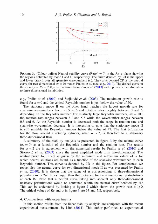
FIGURE 3. (Colour online) Neutral stability curve (Re(σ ) = 0) in the Re–α plane showingthe regions delimited by mode I and II, respectively. The curve denoted by 3D is the upperand lower branch over all spanwise wavenumbers (κ). The curve denoted 2D is the neutralcurve for two-dimensional (κ = 0) modes Pralits et al. (see, e.g., 2010). The dashed curve inthe vicinity of Re = 200, α = 0 is taken from Rao et al. (2013) and represents the bifurcationto three-dimensional instabilities.
e.g., Pralits et al. (2010) and Stojkovic et al. (2003). The maximum growth rate isfound for κ = 0 and the critical Reynolds number is just below the value of 50.
The stationary mode II on the other hand, reaches the largest growth rate forspanwise wavenumbers from ∼0.5 to 6 and rotation rates roughly between 3 and 6,depending on the Reynolds number. For relatively large Reynolds numbers, Re = 100,the rotation rate ranges between 3.7 and 5.3 while the wavenumber ranges between0.5 and 6. As the Reynolds number is decreased both the range in rotation rate andspanwise wavenumber decrease. It is interesting to note that the stationary mode IIis still unstable for Reynolds numbers below the value of 47. The first bifurcationfor the flow around a rotating cylinder, when α > 2, is therefore to a stationarythree-dimensional flow.
A summary of the stability analysis is presented in figure 3 by the neutral curve(σr = 0) as a function of the Reynolds number and the rotation rate. The resultsfor α < 2 are in agreement with the numerical results by Pralits et al. (2010) andStojkovic et al. (2003) since the most amplified mode I is two-dimensional. Theneutral curve for α > 2 is given by the minimum and maximum values of α forwhich neutral solutions are found, as a function of the spanwise wavenumber, at eachReynolds number. This curve is denoted by 3D in the figure. For completeness wereport also the neutral curve for two-dimensional mode II as was presented by Pralitset al. (2010). It is shown that the range of α corresponding to three-dimensionalperturbations is 2–3 times larger than that obtained for two-dimensional perturbationsat each Re. Note that a neutral curve taking into account only three-dimensionalunsteady perturbations would be contained within the neutral curve denoted by 2D.This can be understood by looking at figure 2 which shows the growth rate σr > 0.The critical values of Re and α in figure 3 are 33 and 5.8, respectively.
4. Comparison with experimentsIn this section results from the linear stability analysis are compared with the recent
experimental measurements by Linh (2011). This author performed an experimental
Three-dimensional instability of the rotating cylinder flow 11
3
2
1
0
–1
–2
–3
1 2 3 4 5 6 7 8 9
1.0
0.8
0.6
0.4
0.2
0
–0.2
–0.4
–0.6
–0.8
–1.0
4
–4
0 10
FIGURE 4. (Colour online) Experiments by Linh (2011) for Re = 206 showing the spanwisevorticity in the x–z plane at a distance 0.56D in the y direction on the side of thestagnation point. From these data Linh (2011) estimated the spanwise wavelength of thethree-dimensional structures to be between λ ≈ 1D–1.5D. The corresponding spanwisewavenumbers are κ = 2π/λ≈ 6.3–4.2.
investigation of the flow past a rotating cylinder in a closed loop channel. Theturbulence intensity was ∼1 %, and the cylinder length to diameter ratio was 25for Re < 500. The latter ensures that the flow remains strictly two-dimensional forlow Reynolds numbers. Dye and particle tracing flow visualization (PTFV) were usedto visualize the flow while a hot-film anemometer and particle image velocimetry(PIV) were employed to obtain flow field measurements. In particular, a Litron lasersystem and a Dantec PIV2100 processor system were used for the PIV where theflow was seeded with glass particles which had a diameter of 10 µm. Measurementswere made in both the streamwise (x–y) plane and the spanwise (x–z) plane forRe = 206, 334, 541, 1067 with α ranging from 0 to 5. No evidence of the unsteadymode II earlier shown in numerical investigations by, e.g., Stojkovic et al. (2003) andPralits et al. (2010) could be found in the experiments.
A periodic stationary pattern was instead observed in the spanwise plane for certainvalues of the rotation rate. The spanwise distribution of vorticity from the PIVmeasurements, which has its axis in the y direction, is shown in figure 4 for Re= 206and α = 4. Here the x–z plane is situated 0.56D away from the cylinder centre inthe y direction on the side of the stagnation point. From this image we can estimatethe spanwise wavelength of the three-dimensional modes to be between λ ≈ 1D–1.5D(values reported in the thesis). These values correspond to spanwise wavenumbersκ = 2π/λ ≈ 6.3–4.2. In order to compare with the experimental results we performeda linear stability analysis for the same parameters (Re, α, κ) and determined the least-stable modes. Their growth rate is presented in figure 5 as a function of the spanwisewavenumber. The linear stability analysis gives the maximum growth rate for thespanwise wavenumber κ ≈ 6 which is within the range of κ’s evaluated from themeasurements by Linh (2011), here indicated by the grey area in the figure. Spanwisestructures, similar to those presented in figure 4, were also found in the experimentby Linh for Re = 206 and α = 3, but not for α = 1, 2, 5. This is also consistent withthe neutral stability curve presented in figure 3. The comparison shows that the linear
12 J. O. Pralits, F. Giannetti and L. Brandt
–0.05
0
0.05
0.10
0.15
0.20
0.25
2 4 6 8 100 12–0.10
0.30
FIGURE 5. (Colour online) Growth rate σr obtained from the linear stability analysis as afunction of κ at Re = 206. The values of κ corresponding to the wavelength’s obtained fromfigure 4 are given by the grey area.
–2
–1
0
1
2
3
4
–2 0 2 4 6–2
–1
0
1
2
3
4
–2 0 2 4 6
0
0.02
0.04
0.06
0.08
0.10
0.12(a) (b)
0
0.02
0.04
0.06
0.08
FIGURE 6. (Colour online) Modulus of the perturbation vorticity |ω(x, y)| at Re = 100 andα = 5; κ = 0 (a) and κ = 1 (b). The black curve shows the streamlines passing through thestagnation point. The contour spacing is 0.02.
stability analysis performed here captures the main characteristics of the wake at highrotation rates and strengthens the results presented in figure 3.
5. The global modesIn this section we visualize the spatial structure of the modes corresponding to
the unstable solutions shown in the previous section. In figure 6 the modulus ofthe vorticity field of mode II is presented for the case in which Re = 100 andα = 5. The three-dimensional stationary mode II, with κ = 1, is compared withthe unsteady two-dimensional counterpart (κ = 0). Both modes are unstable and thewavenumber for the stationary mode was chosen to maximize the growth rate (cf.figure 1). At this Reynolds number and rotation rate the streamlines crossing thestagnation point forms a closed loop around the cylinder. The spatial structures ofthe unsteady and stationary unstable modes are similar but the stationary mode hasthe maximum value of the vorticity modulus aligned with the direction of maximumstrain of the base flow. Implications of this alignment is discussed later in this section.Figure 7 shows the spatial structure of the perturbation velocity for the stationary
Three-dimensional instability of the rotating cylinder flow 13
–2
–1
0
1
2
3
4
–2 0 2 4 6
–2
–1
0
1
2
3
4
–2 0 2 4 6
–2
–1
0
1
2
3
4
–2 0 2 4 6
–2
–1
0
1
2
3
4
–2 0 2 4 6
0.1
0.3
0.5
0.7
0.9
–0.4
–0.2
0
0.2
–0.1
0.1
0.3
0.5
0.7
–0.2
0
0.4
0.2
0.6
(a) (b)
(c) (d )
FIGURE 7. (Colour online) Spatial structure of the perturbation velocity at Re = 100, α = 5and κ = 1: (a) modulus; (b) horizontal component u; (c) vertical component v; (d) spanwisecomponent w. The mode has been normalized such that the maximum of the modulus is 1.The contour spacing is 0.05 and continuous lines are positive values while dashed lines arenegative values.
mode II at Re = 100, α = 5 and κ = 1. Here both the modulus and the three velocitycomponents are displayed: as can be easily noticed the mode grows in the regionaround the hyperbolic point, mainly inside the closed loop delimited by the streamlinescrossing the stagnation point. A deeper knowledge of the instability characteristics canbe gained using the concept of a wave-maker that is related to the region in spacewhere a modification in the structure of the problem produces the largest drift of theeigenvalue. This is done by determining the region where feedback from velocity toforce is most effective. This concept was introduced for the first time in Giannetti &Luchini (2007) in the context of a linear stability analysis on a steady base flow andlater generalized in Luchini, Giannetti & Pralits (2008) to time-periodic flows. Thesensitivity tensor Sp derived by Giannetti & Luchini (2007) is given by
Sp(x0, y0, κ)= u?(x0, y0, κ) u(x0, y0, κ)∫D
u? · u dS, (5.1)
where u? is the adjoint perturbation velocity, and u? u indicates the dyadic productbetween the direct and adjoint modes. Different norms of the tensor Sp can be used tobuild a spatial map of the sensitivity. In figure 8 the spectral norm of the sensitivitytensor Sp is presented for the same parameters used in figure 6. The maximum value isfound in the vicinity of the stagnation point both for unsteady and stationary mode II,moreover, aligned with the direction of compression. The sensitivity of the stationarymode, however, is smaller in magnitude and its spatial structure presents a second
peak in a region very close to the hyperbolic stagnation point. This fact suggests someconsiderations on the nature of the stationary mode II.
It is well known that in an inertial frame any inviscid incompressible flow witha stagnation point is unstable to short wavelength perturbations, no matter whichtype of flow surrounds it (see Friedlander & Vishik 1991; Lifschitz & Hameiri1991). Various growth mechanisms have been presented to explain the developmentof such instabilities, depending on the elliptic or hyperbolic nature of the stagnationpoint. In the hyperbolic case the instability can be understood physically in termsof the stretching of the vorticity perturbations and the tilting of the velocity by thetwo-dimensional background flow. Such mechanism is an example of the so-called‘Orr mechanism’ and leads transiently to elevated growth. Asymptotically this inviscidmechanism leads to exponentially growing modes with a velocity vector which alignswith the principal direction of compression of the base flow while the vorticityultimately approaches a direction perpendicular to it (see Leblanc & Godeferd 1999;Caulfield & Kerswell 2000).
For idealized flows such as those characterized by a quadratic streamfunction, infact, the maximum growth rate is attained by the so-called ‘pressureless modes’which have a velocity perturbation that is purely two-dimensional (w = 0). Moreover,provided that the magnitude of the spanwise wavenumber is sufficiently large, theperturbation is predicted to grow even in a viscous flow, since the stabilizing effect ofthe fluid viscosity is dominated by the growth of the perturbation. As already noted,the flow around the rotating cylinder is characterized by the existence of a hyperbolicstagnation point whose position depends on the values of the Reynolds number Reand of the rotation rate α. In its proximity, the velocity perturbation vector is alignedwith the direction of compression and has a spanwise component significantly smallerthan the streamwise and vertical components. This can be clearly seen in figure 9(a) inwhich three different lines are drawn. The white one is the streamline of the base flowpassing through the stagnation point, while the other two are obtained by integrationof the differential equations dx/dt = f (x) where the vector field f is taken to be themode velocity (black line) and the mode vorticity (dashed line). The computationsare performed in three dimensions, both forward and backward in time, with theinitial seeds taken along the stagnation line. Since the corresponding global mode isstationary, these lines are parallel in each point to the corresponding vector fields usedto generate them. The black lines in particular are therefore the streamlines of theunstable mode and can be used to better visualize its spatial structure in proximity to
Three-dimensional instability of the rotating cylinder flow 15
yxz
zyx
–1.0 0.5
–0.8 –0.4 0.40w
(a)
(b)
FIGURE 9. (Colour online) (a) Streamlines at Re = 100, α = 5, κ = 1, passing through thehyperbolic point; base flow (white); mode (black). The dashed curve passes the stagnationpoint parallel to the perturbation vorticity. The colour map shows the spanwise componentin an x–y plane where it reaches its maximum. The mode is normalized such that ‖u‖ = 1.(b) Three-dimensional view of the mode streamlines passing through the stagnation line. Thecolour map represents the modulus of the perturbation velocity in a plane where the spanwisecomponent vanishes. The white line is the streamline of the base flow passing through thehyperbolic point.
the hyperbolic point. The colour map in the background corresponds to the spanwisecomponent of the perturbation velocity on a plane where it reaches its maximum.
Figure 9(b) shows a three-dimensional view of the mode streamlines passingthrough the stagnation point and shows that in its proximity the perturbation velocityis contained in the plane tangent to the stagnation line (in white). The colour mapat the base of the figure shows the modulus of the perturbation velocity in a planewhere the w component vanishes. Note that the mode maximum is located close tothe hyperbolic point. Thus, at least locally, there is a qualitative resemblance withthe ‘pressureless’ perturbations described by Leblanc & Godeferd (1999) and Caulfield& Kerswell (2000). Note also that for the rotating cylinder the maximum growthrate is reached for values of the wavenumber κ = O(1): this fact prevents us from amore quantitative comparison with the asymptotic theory, which is only valid in thelarge wavenumber limit. Furthermore, as we move away from the stagnation point,the flow quickly differs from a linear flow, so that the final growth rate is certainlyinfluenced by the non-local characteristics of the base flow. This is also confirmed bythe structural sensitivity analysis (figure 8) which shows that the instability mechanism
16 J. O. Pralits, F. Giannetti and L. Brandt
–2
–1
0
1
2
3
4
–2 0 2 4 6–2
–1
0
1
2
3
4
–2 0 2 4 6
(a) (b)
0
40
80
120
0
5
10
15
FIGURE 10. (Colour online) Structural sensitivity Sb for Re = 100, α = 5: (a) κ = 0;(b) κ = 1. The black curve shows the streamlines passing through the stagnation point. Thecontour spacing is (a) 3, (b) 24.
is localized inside the area delimited by the streamline passing through the stagnationpoint, in a region close to the hyperbolic point, but not exactly centred on it.
In theory, it is possible that other instability mechanisms act and cooperate togenerate the unstable mode. For example, the region of the flow delimited externallyby the stagnation streamline and internally by the cylinder is characterized by thepresence of closed streamlines and can be prone to a centrifugal instability. Thisinviscid mechanism is due to the disruption of the balance between the centrifugalforce and the radial pressure gradient and usually gives rise to modes whichare localized along particular streamlines, with a transverse spatial structure whichgenerally decays exponentially fast. Although viscosity and small wavenumbers effectscan modify the structure of these modes considerably, the distinguishing characteristicsof a centrifugal instability are not visible in the results presented in this study, at leastin the range of parameters investigated. Thus, even if a more detailed investigation(which is outside the scope of this paper) is necessary to clarify the nature of thestationary instability, the main characteristics of the mode and the sensitivity analysispresented here strongly suggest that the stationary mode II is of hyperbolic nature.
In this last part we show the sensitivity tensor Sb due to base flow modifications.The importance of analysing this quantity was discussed in detail in the work byPralits et al. (2010) and is related to modifications of the basic flow induced by smallobjects such as e.g. a control cylinder whose purpose is to act as a passive controldevice. The expression of the sensitivity tensor can be written
Sb(x0, y0, κ)= Ub?(x0, y0)Ub(x0, y0)∫
D
u? · u dS, (5.2)
where Ub? is the solution of the adjoint base flow equations (see Pralits et al. 2010,
for a complete derivation). In figure 10 the spectral norm is shown for the sameparameters used in figures 6 and 8. The maximum sensitivity of the stationary three-dimensional mode II is approximately ten times that of the unsteady two-dimensionalmode II. Further, the largest sensitivity of the stationary mode is located inside theclosed streamlines on the lee-ward side of the stagnation point, while the unsteadymode has its maximum outside the closed streamlines. The results imply that differentregions in space are important when it concerns control of the wake flow.
Three-dimensional instability of the rotating cylinder flow 17
6. ConclusionsIn this paper we have presented a linear stability analysis of the flow past a
rotating cylinder and investigate the onset two-dimensional and three-dimensionalbifurcations. We find a reasonable explanation for the discrepancies between numericaland experimental findings existing so far at large rotation rates. In this regime, allconditions being equal, if an unstable two-dimensional unsteady solution exists thena three-dimensional stationary unstable solution also exists but with a larger growthrate. As a consequence, the unsteady shedding mode II cannot be observed inlaboratory experiments. Further, the stationary three-dimensional solution is unstablefor Reynolds numbers below the critical value of two-dimensional instabilities. Wereport for the first time the complete neutral curve as a function of the Reynoldsnumber and rotation rate and identify the absolute critical value of (Re, α) = (33, 5.8).Recent experimental investigations by Linh (2011) confirm the onset of stationarythree-dimensional structures at high rotation values with a spanwise periodicity inagreement with our prediction. The structure and the characteristics of the resultingmode, if compared with results obtained using asymptotic theory on inviscid linearflows, suggest that the stationary unstable three-dimensional mode could be the resultof a hyperbolic instability.
AcknowledgementThe authors wish to thank D. Fabre for the fruitful discussions on hyperbolic and
centrifugal instabilities.
R E F E R E N C E S
BARKLEY, D. & HENDERSON, R. D. 1996 Three-dimensional Floquet stability analysis of the wakeof a circular cylinder. J. Fluid Mech. 322, 215–241.
BARNES, F. H. 2000 Vortex shedding in the wake of a rotating circular cylinder at low Reynoldsnumbers. J. Phys. D: Appl. Phys. 33, L141–L144.
CAULFIELD, C. P. & KERSWELL, R. R. 2000 The nonlinear development of three-dimensionaldisturbances at hyperbolic stagnation points: a model of the braid region in mixing layers.Phys. Fluids 12 (5), 1032–1043.
ELAKOURY, R., BRAZA, M., PERRIN, R., HARRAN, G. & HOARAU, Y. 2008 The three-dimensional transition in the flow around a rotating cylinder. J. Fluid Mech. 607,1–11.
FRIEDLANDER, S. & VISHIK, M. M. 1991 Instability criteria for the flow of an inviscidincompressible fluid. Phys. Rev. Lett. 66, 2204–2206.
GIANNETTI, F. & LUCHINI, P. 2007 Structtural sensitivity of the first instability of the cylinderwake. J. Fluid Mech. 581, 167–197.
KANG, S., CHOI, H. & LEE, S. 1999 Laminar flow past a rotating circular cylinder. Phys. Fluids 11(11), 3321.
LEBLANC, S. & GODEFERD, F. S. 1999 An illustration of the link betwen ribs and hyperbolicinstability. Phys. Fluids 11 (2), 497–499.
LIFSCHITZ, A. & HAMEIRI, E. 1991 Local stability conditions in fluid dynamics. Phys. Fluids A 3(11), 2644–2651.
LINH, D.T. T. 2011 Flow past a rotating circular cylinder. PhD thesis, Department of MechanicalEngineering, National University of Singapore.
LUCHINI, P., GIANNETTI, F. & PRALITS, J. O. 2008 Structural sensitivity of linear and nonlinearglobal modes. In Proceedings of 5th AIAA Theoretical Fluid Mechanics Conference, Seattle,Washington, USA, Paper AIAA-2008-4227.
MITTAL, S. 2004 Thee-dimensional instabilities in flow past a rotating cylinder. J. Appl. Mech. 71,89–95.
18 J. O. Pralits, F. Giannetti and L. Brandt
MITTAL, S. & KUMAR, B. 2003 Flow past a rotating cylinder. J. Fluid Mech. 476, 303–334.NOACK, B. R. & ECKELMANN, H. 1994 A global stability analysis of the steady and periodic
cylinder wake. J. Fluid Mech. 270, 297–330.PRALITS, J. O., BRANDT, L. & GIANNETTI, F. 2010 Instability and sensitivity of the flow around a
rotating circular cylinder. J. Fluid Mech. 650, 513–536.PROVANSAL, M., MATHIS, C. & BOYER, L. 1987 Benard–von Karman instability: transient and
forced regimes. J. Fluid Mech. 182, 1–22.RAO, A., LEONTINI, J., THOMPSON, M. C. & HOURIGAN, K. 2013 Three-dimensionality in the
wake of a rotating cylinder in a uniform flow. J. Fluid Mech. 717, 1–29.STOJKOVIC, D., BREUER, M. & DURST, F. 2002 Effect of high rotation rates on the laminar flow
around a circular cylinder. Phys. Fluids 14 (9), 3160–3178.STOJKOVIC, D., SCHON, P., BREUER, M. & DURST, F. 2003 On the new vortex sheddng mode
past a rotating circular cylinder. Phys. Fluids 15 (5), 1257–1260.WILLIAMSON, C. H. K. 1996 Vortex dynamics in the cylinder wake. Annu. Rev. Fluid Mech. 28,
477–539.YILDIRIM, I., RINDT, C. C. M., VAN STEENHOVEN, A. A., BRANDT, L., PRALITS, J. O. &
GIANNETTI, F. 2008 Identification of shedding mode ii behind a rotating cylinder. In SeventhEuropean Fluid Mechanics Conference, Manchester, UK. Book of abstracts, p. 371.