26
REPORT ENGINEERING DRAWING NAME : SITI NURUL SHAFIQAH BT RAMLI REG. NUM : 04DPT15F1044 LECTURER NAME :
| Date post: | 07-Dec-2015 |
| Category: |
Documents |
| Upload: | mohd-hafiz |
| View: | 217 times |
| Download: | 3 times |
REPORT ENGINEERING
DRAWINGNAME : SITI NURUL SHAFIQAH BT RAMLI
REG. NUM : 04DPT15F1044
LECTURER NAME :
INTRODUCTION
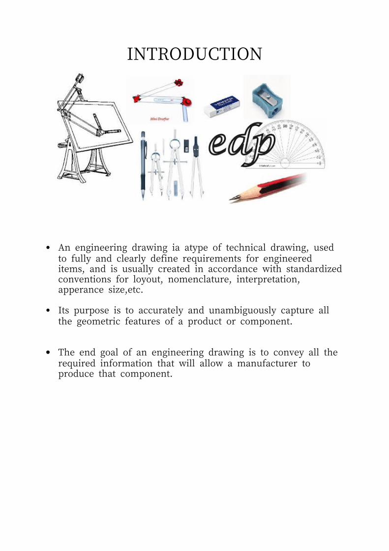
An engineering drawing ia atype of technical drawing, used to fully and clearly define requirements for engineered items, and is usually created in accordance with standardized conventions for loyout, nomenclature, interpretation, apperance size,etc.
Its purpose is to accurately and unambiguously capture all the geometric features of a product or component.
The end goal of an engineering drawing is to convey all the required information that will allow a manufacturer to produce that component.
OBJECTIVE Be able to understand the basic rules of dimensioning.
Apply dimensions to objects in accordance with engineering standards.
Define the following items:
- Dimension line
- Extension line
- Reference dimension
- Leader
TYPE OF CONTENTBIL CONTENT PAGE1. PAGE COVER2. INTRODUCTION3. OBJECTIVE4. TYPE OF
CONTENT5. CONTENT :
i) SECTIONAL VIEW.
ii) ASSEMBLY DRAWING.
iii) DETAIL DRAWING.
iv) SYMBOL.
6. CONCLUSION
Sectional Views
INTRODUCTIONIn engineering drawing, various objects have invisible or hidden interior features, which are represented by dotted lines in their projection views. But, when the features, are too many, the orthographic projections obtained get complicated and difficult to understand. In order to understand the interior view details, the object is cut an imaginary cutting plane called Sectional Plane. The part of the object between the cutting plane and the observer is assumed to be removed and view is then shown in section. The view thus obtained is called Sectional View.
Sectional View
The view obtained by cutting an object with an imaginary cutting plane is called Sectional View.The surface produced by cutting the object by the section plane is called Section. It is indicated by thin section lines uniforemly spaced, generally at an angle of 45'. As already imagined, a sectional view is a view seen when a portion of the object nearest to the observer is imagined to be removed by means of a cutting plane or planes, thus revealing the interior construction. The other views are not affected in any way always represent the entire object.
Types Of Sectional Views
The sectional views are of mainly two types. These are dependent upon the number of cutting planes cutting the object.
1. Full Sectional View.2. Half Sectional View.
Full Sectional View
The view obtained after removing the front half portion of an object is called a Full Sectional Views or Front Sectional Views or Simply Sectional Elevation.When the cutting plane cuts the object lengthwise, full sectional front view is obtained. It is also called longitudinal section. It may be noted that the top view or the slide remain unaffected, that means top view is drawn full not half.
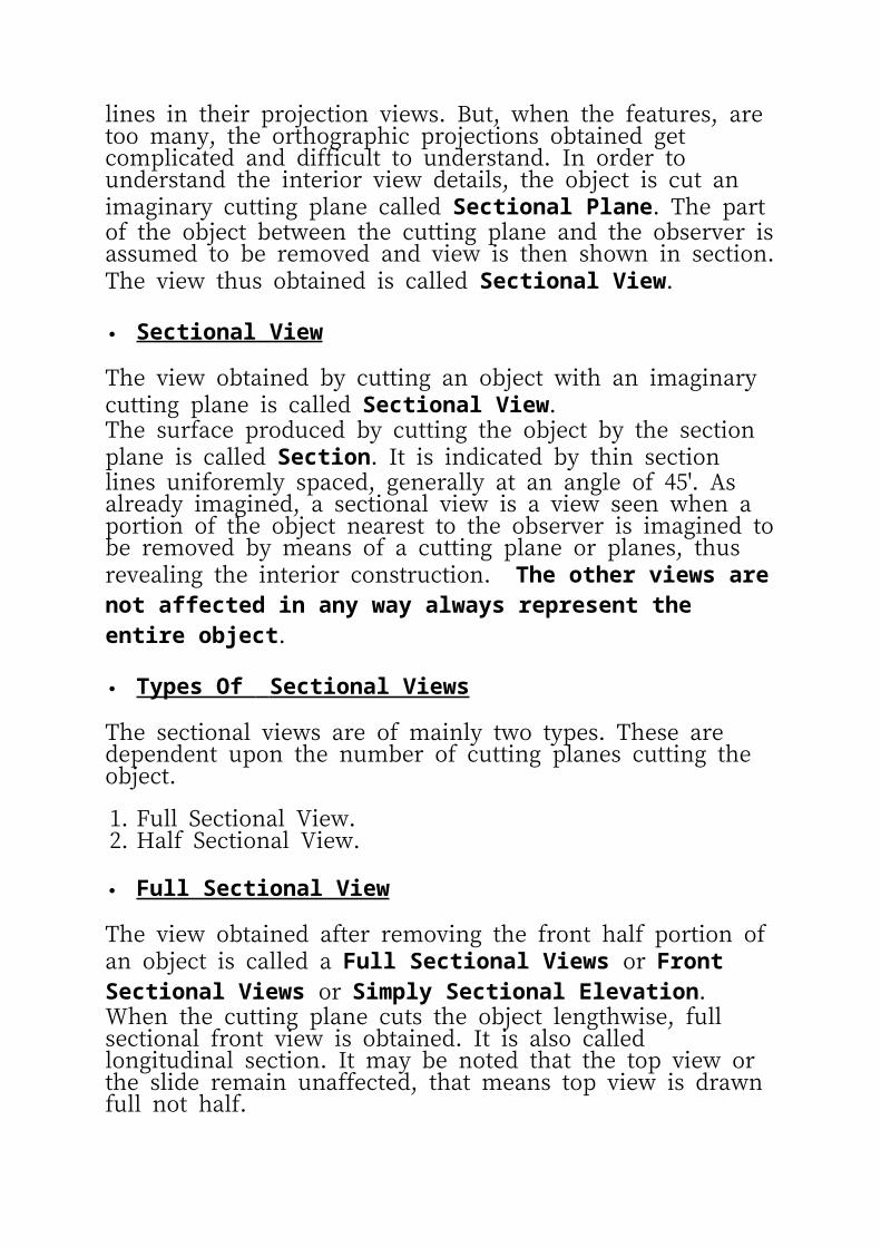
The Cutting Plane The cutting plane is shown in a view adjacent to the
sectional view. In the section view, the areas that would have been in
actual contact with the cutting plane are show with section lining.
Lines Behind the Cutting Plane The visible edges of the object behind the cutting plane
are generally shown because they are now visible but they are not cross-hatched.
The Cutting Plane
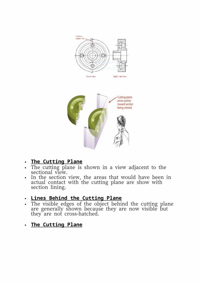
Placement of Section Views Section views can replace the normal top, front, side, or
other standard orthographic view.
Placement of Section Views
Labeling Cutting Planes When more than one cutting plane is used, it is
especially important to label them for clarity.
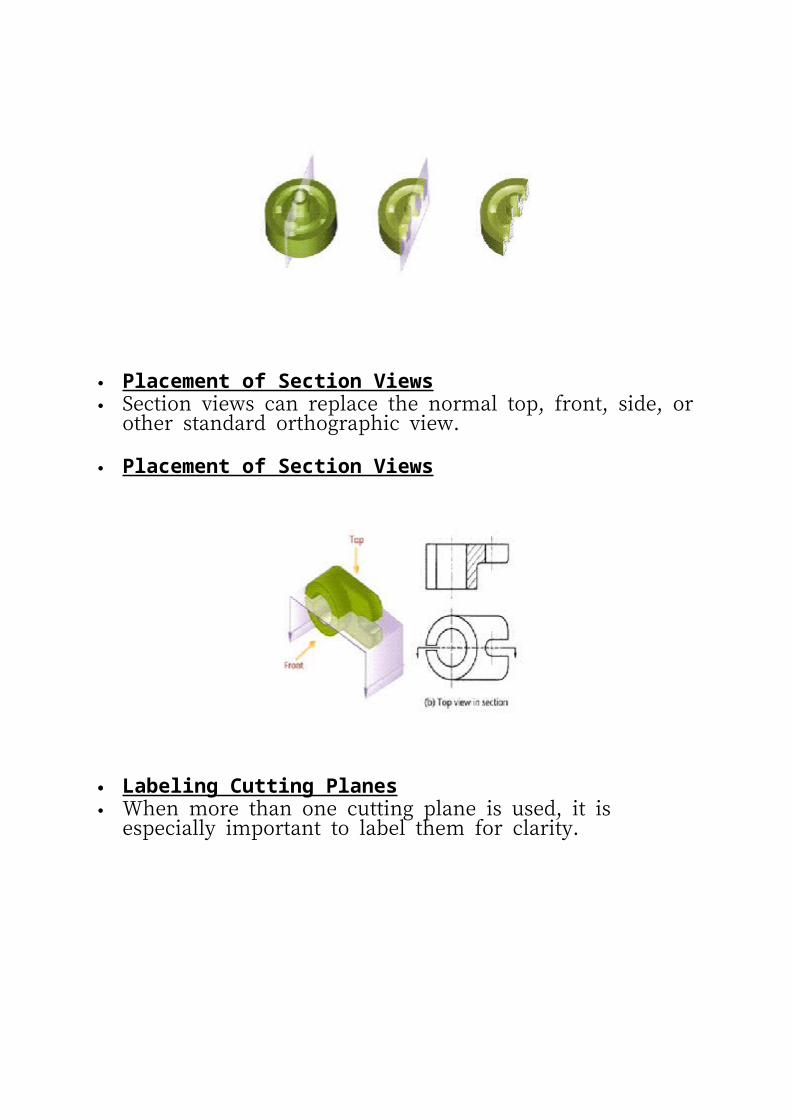
Line Precedence When a cutting plane coincides with a center line, the
cutting plane line takes precedence. When a cutting plane line would obscure important
details, just the ends of the line outside the view and the arrows can be shown.
Rules for Lines Show edges and contours which are now visible behind
the cutting plane. Omit hidden lines in section views.
A section-lined area is always completely bounded by a visible outline.
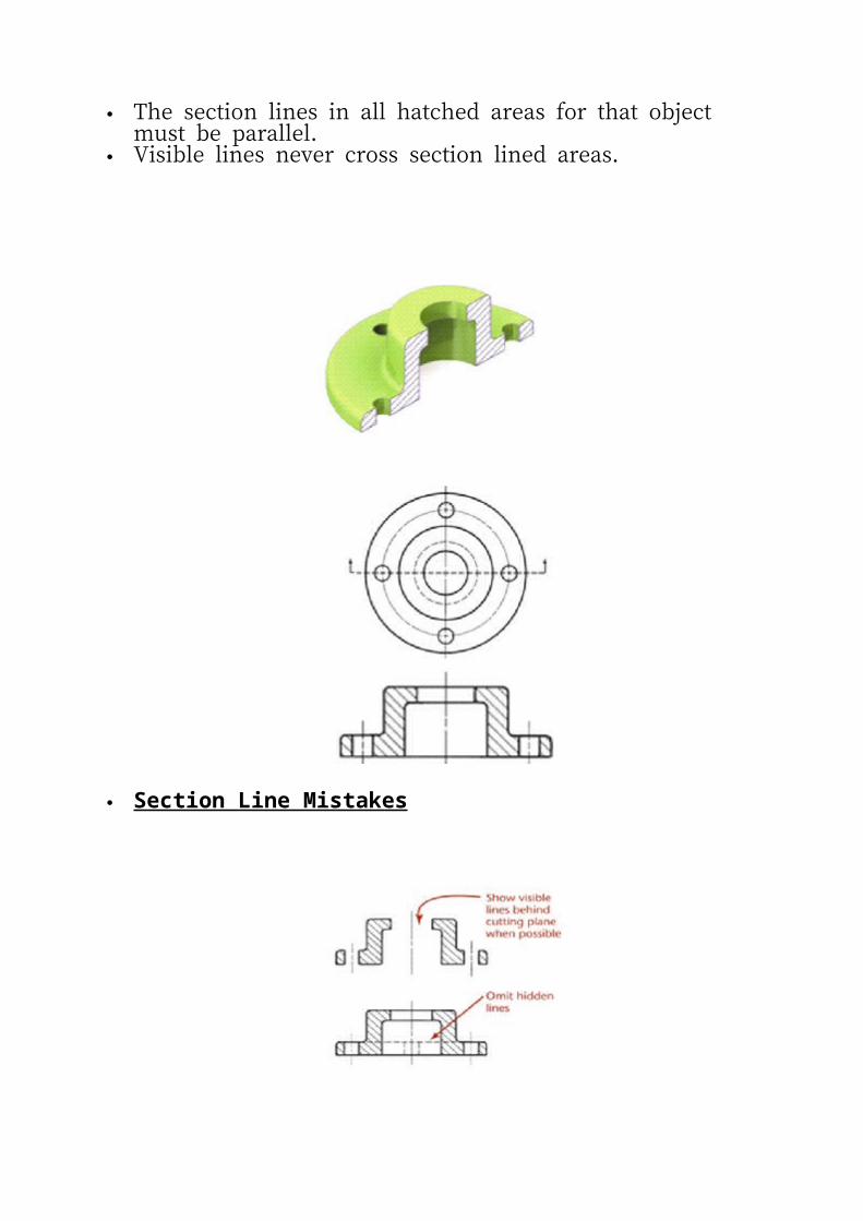
The section lines in all hatched areas for that object must be parallel.
Visible lines never cross section lined areas.
Section Line Mistakes
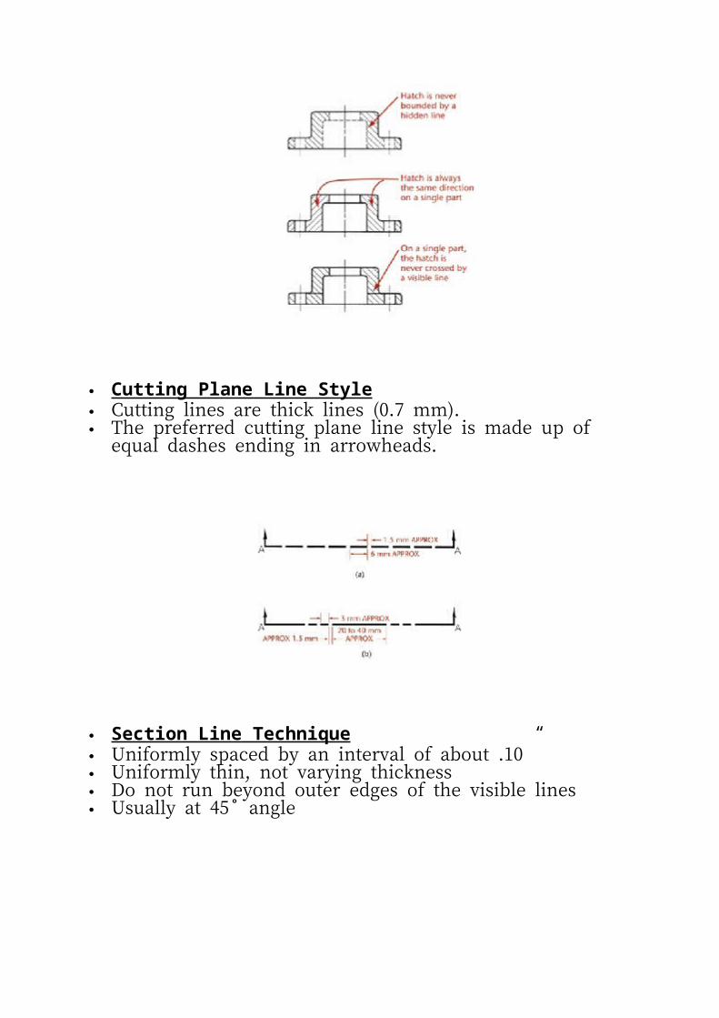
Cutting Plane Line Style Cutting lines are thick lines (0.7 mm). The preferred cutting plane line style is made up of
equal dashes ending in arrowheads.
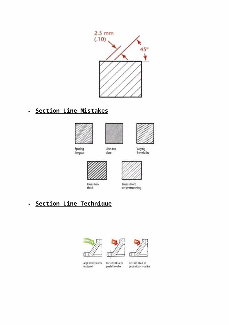
Section Line Technique Uniformly spaced by an interval of about .10” Uniformly thin, not varying thickness Do not run beyond outer edges of the visible lines Usually at 45˚ angle
Section Line Mistakes

Section Line Technique
Section Lining Symbols
Half Sections
The view obtained after removing the front quarter i.e. one fourth portion of an object by means of two cutting planes at right angle to each other is called Half Sectional View or Half Sectional Elevation.It may be observed that the plane or top view also remain unaffected i.e. full side view is drawn.
ASSEMBLY DRAWINGSOBJECTIVE
This chapter is related with the formal ways of presenting a part to be manufactured in detail and the structures that is formed by several parts aligned to each others by appropriate assembly elements such as threaded fasteners, keys, springs, etc.
WORKING DRAWINGS NEEDED FOR PRODUCTION
The drawings that are used to give information for the manufacture or construction of a machine are called as working drawings. Working drawings must include all the knowledge for the production of a machine or structure explicitly so that no further information is required to complete the production. The description given by the set of working drawings will include:
1. The graphical representation of the shape of each part, namely shape description.
2. The dimensions of each part; size description. 3. Explanatory notes on the individual drawings, giving the
specifications of material, heat treatment, and surface finish. 4. A descriptive title on each drawing. 5. Relationships of each part to the others (in assembly
drawings) 6. Part list.
In general, set of drawings include two classes of drawings; detail drawings, supplying the information in topics 1 to 4, and an assembly drawing, supplying the information about the location and relationship of the parts, topic 5.
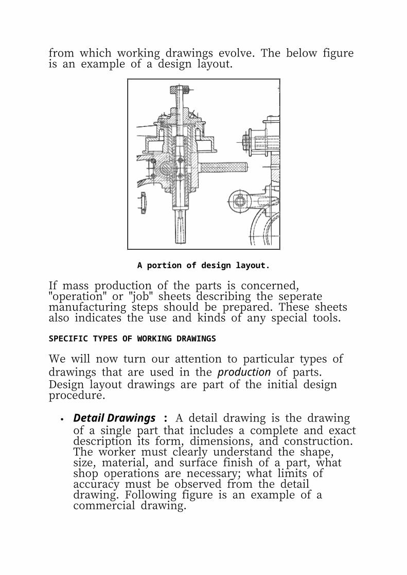
It must be noted that the working drawings used for purposes of manufacturing are superior to design layouts. Design layouts are prototype assembly drawings from which working drawings evolve. The below figure is an example of a design layout.

A portion of design layout.
If mass production of the parts is concerned, "operation" or "job" sheets describing the seperate manufacturing steps should be prepared. These sheets also indicates the use and kinds of any special tools.
SPECIFIC TYPES OF WORKING DRAWINGS
We will now turn our attention to particular types of drawings that are used in the production of parts. Design layout drawings are part of the initial design procedure.
Detail Drawings : A detail drawing is the drawing of a single part that includes a complete and exact description its form, dimensions, and construction. The worker must clearly understand the shape, size, material, and surface finish of a part, what shop operations are necessary; what limits of accuracy must be observed from the detail drawing. Following figure is an example of a commercial drawing.
A commercial detail drawing.
Detail drawings are formed by carefully studying the initial design layouts. Use is made of the scale of the design layout, dimensions that may be given, and all notes provided. Approved standarts for the specific company involved with respect to lettering style, dimensioning techniques, position of notes must be included in detail drawings.
In general working drawings are checked by an experinced person responsible for any possible error, when it is finished. This step is the final "proofreading" and cannot be carried out by the person who has made the drawing. The necessary information should be preserved for the future use and reference.
Assembly Drawings : A complete assembly drawing is presentation of the product or structure put together, showing all parts in their operational positions. The seperate parts come to the assembly department after their manufacturing processes are finssihed and in this department they are put together according the assembly
drawings. Small machining operations may be necessary during assembly process such as drilling, reaming, or hand finishing. For such cases, assembly drawings include a note explaining the required operation and give the dimensions for the alignment or location of the pieces.
Several different methods can be used to produce assembly drawings; the simplest one tracing from the design layouts. This method is inferior to the method that the assembly drawing is produced from the dimensions of detail drawings if the accuracy of checking considered. Of course the second method is very time consuming. Whereas, the Computer Aided Drafting can be a huge timesaver when an assembly drawing is being produced. Nowadays, there are so sofisticated CAD programs and equipments; almost all the manufacturers use these programs to recover high initial costs. Although many assembly drawings do not need dimensions, the overall dimensions and distances between the centers or from part to part of the different pieces to clarify the relationship of the parts with each others. An assembly drawing should not be overloaded with detail.
Assembly drawings should include referance letters and numbers representing the different parts. These part numbers usually enclosed by circles with a leader pointing to the piece .
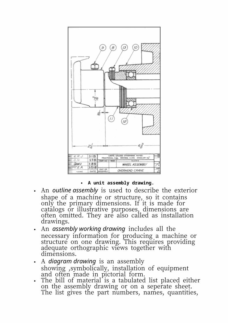
A unit assembly (subassembly) is a drawing of a related group of parts and used to show the assembly of complicated machinery for which it would be practically impossible to show all the features on one drawing. To illlustrate; headstock, tailstock, and gearbox unit assemblies should be included in the drawing of a lathe.
A unit assembly drawing.
An outline assembly is used to describe the exterior shape of a machine or structure, so it contains only the primary dimensions. If it is made for catalogs or illustrative purposes, dimensions are often omitted. They are also called as installation drawings.
An assembly working drawing includes all the necessary information for producing a machine or structure on one drawing. This requires providing adequate orthographic views together with dimensions.
A diagram drawing is an assembly showing ,symbolically, installation of equipment and often made in pictorial form.
The bill of material is a tabulated list placed either on the assembly drawing or on a seperate sheet. The list gives the part numbers, names, quantities, material and sometimes stock sizes of raw material, detail drawing number, etc. The
term "bill of material" is usually used in structural and architectural drawing whereas the term "part list" is used in machine-drawing practice.
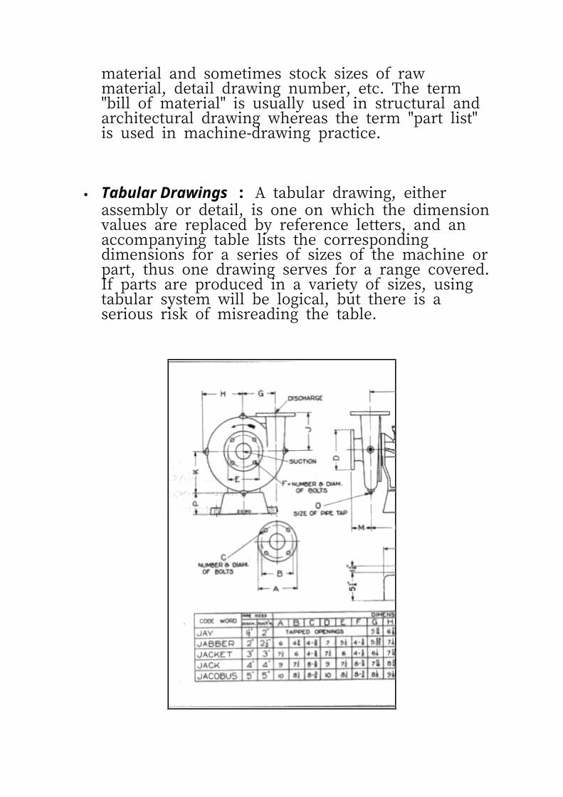
Tabular Drawings : A tabular drawing, either assembly or detail, is one on which the dimension values are replaced by reference letters, and an accompanying table lists the corresponding dimensions for a series of sizes of the machine or part, thus one drawing serves for a range covered. If parts are produced in a variety of sizes, using tabular system will be logical, but there is a serious risk of misreading the table.
An outline assembly drawing (tabular).
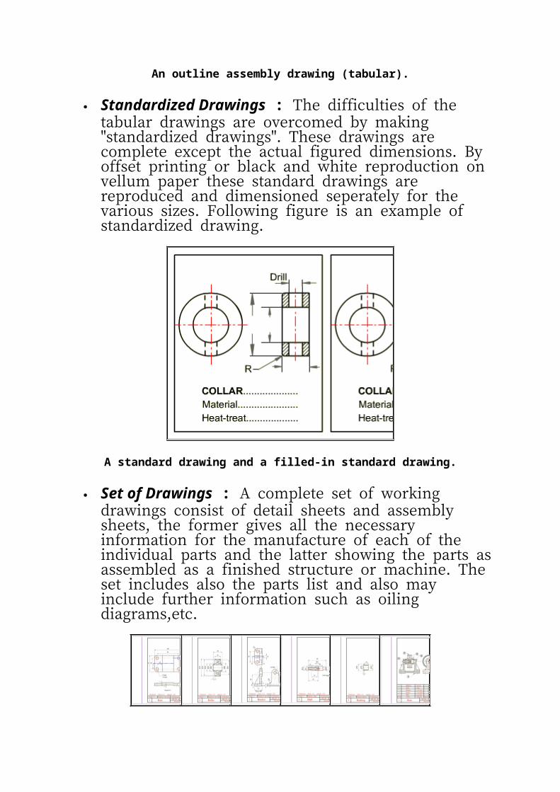
Standardized Drawings : The difficulties of the tabular drawings are overcomed by making "standardized drawings". These drawings are complete except the actual figured dimensions. By offset printing or black and white reproduction on vellum paper these standard drawings are reproduced and dimensioned seperately for the various sizes. Following figure is an example of standardized drawing.
A standard drawing and a filled-in standard drawing.
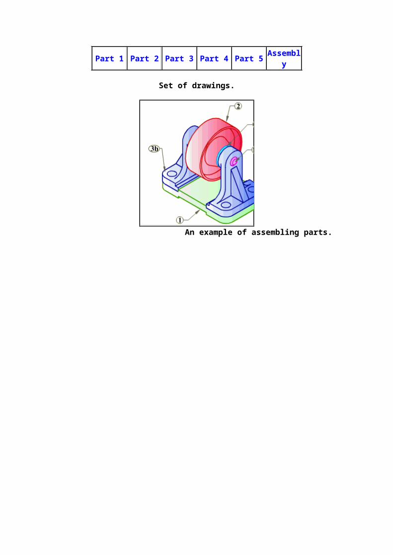
Set of Drawings : A complete set of working drawings consist of detail sheets and assembly sheets, the former gives all the necessary information for the manufacture of each of the individual parts and the latter showing the parts as assembled as a finished structure or machine. The set includes also the parts list and also may include further information such as oiling diagrams,etc.
Part 1 Part 2 Part 3 Part 4 Part 5 Assembly
Set of drawings.
An example of assembling parts.
DETAIL DRAWING
Detail Drawings must provide sufficient information to enable the manufacture a part.•Enough orthogonal views : enough views to adequate describe the component. •Dimensions : Must be evenly distributed, structured and not duplicated. •Scale : Drawing must state the scale used to fit the component onto the drawing sheet.•The type of projection : Third Angle Projection is mandatory in ENGG1960.•Drafting Standard (AS1100) : This is effectively covered in prescribed texts.•The name or title of drawing : What is the name of the component ? •The drawing number : What is the number (in-house system) of the component ?•Dimensional units used : mm, m, inches, feet etc.•Tolerances : What are the manufacturing tolerances for each part of the component.
•Surface texture (or roughness) : How smooth/rough each part of the component has to be.•Treatments (coatings, tempers etc.) : Does the component need protective coatings ?•Reference to assembly drawing : What does my component fit into ? •Material : What material is the component manufactured from ?•Drafter (who drew it), Checker (who checked it), Approver (who approved it) and dates•Zones : Where on the drawing are you referring to ?•Revision : What has been revised and why and what revision is this drawing ?•Sheet Size : A4, A3, A2, A1 or A0•Company : School of AMME, University of Sydney•Sheets Reference (eg. Sheet 1 of 3) : When more than one sheet is required.
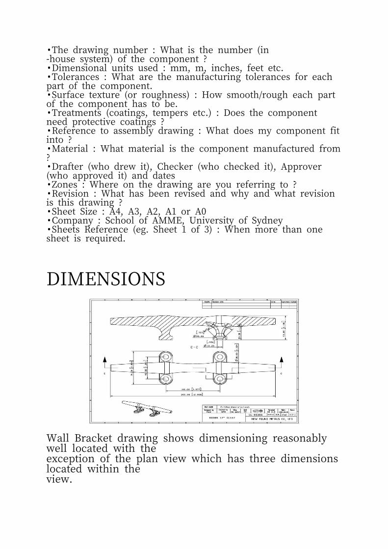
DIMENSIONS
Wall Bracket drawing shows dimensioning reasonably well located with the exception of the plan view which has three dimensions located within the view.
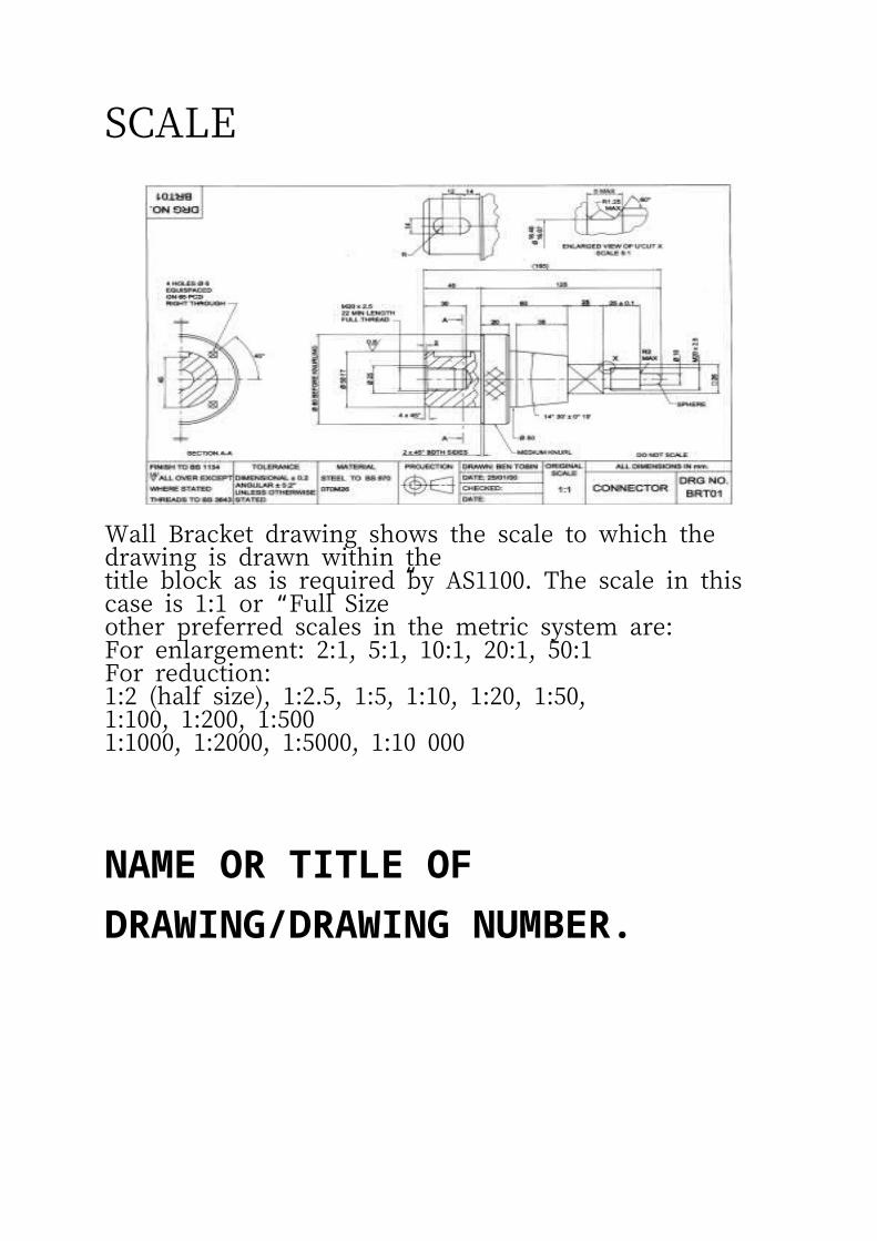
SCALE
Wall Bracket drawing shows the scale to which the drawing is drawn within the title block as is required by AS1100. The scale in this case is 1:1 or “Full Size” other preferred scales in the metric system are:For enlargement: 2:1, 5:1, 10:1, 20:1, 50:1For reduction: 1:2 (half size), 1:2.5, 1:5, 1:10, 1:20, 1:50,1:100, 1:200, 1:5001:1000, 1:2000, 1:5000, 1:10 000
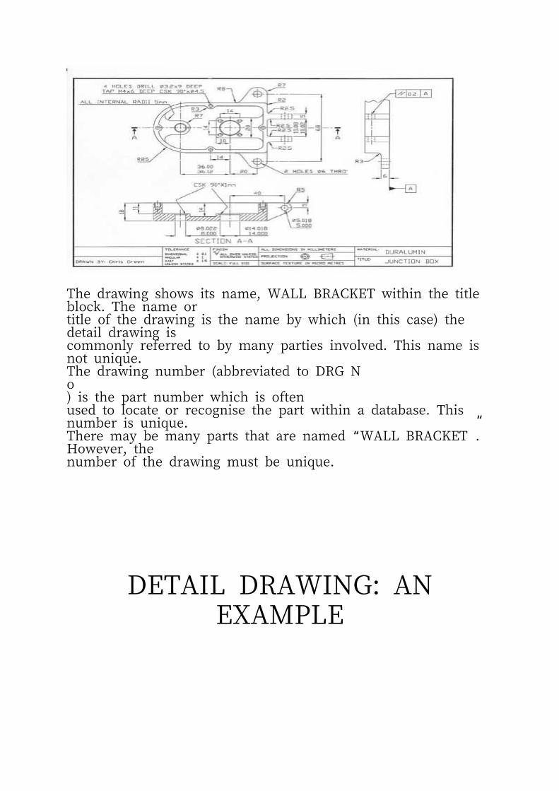
NAME OR TITLE OF DRAWING/DRAWING NUMBER.
The drawing shows its name, WALL BRACKET within the title block. The name or title of the drawing is the name by which (in this case) the detail drawing is commonly referred to by many parties involved. This name is not unique. The drawing number (abbreviated to DRG No) is the part number which is often used to locate or recognise the part within a database. This number is unique.There may be many parts that are named “WALL BRACKET”. However, the number of the drawing must be unique.
DETAIL DRAWING: AN EXAMPLE
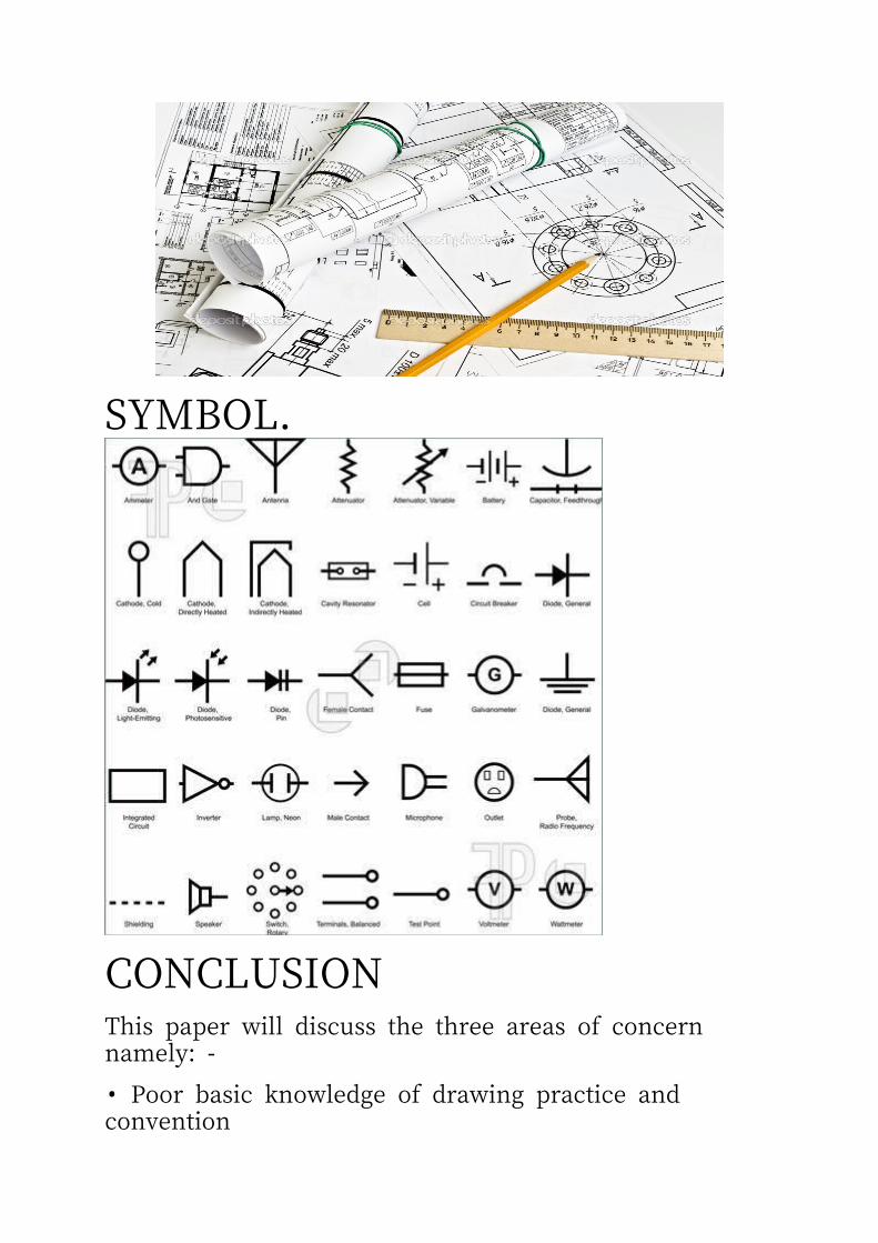
SYMBOL.
CONCLUSIONThis paper will discuss the three areas of concern namely: -
• Poor basic knowledge of drawing practice and convention

• Poor sketching ability
• Lack of CAD tuition
The paper will suggest that by replacing hand draughting of engineering drawings by CAD techniques time will be freed up for more rigorous tuition in drawing conventions and the practice of sketching. This augmented by lectures and phase tests for the knowledge elements and the use CAD as the primary tool for the teaching and learning engineering drawing should lead to an improvement in standards and better engagement of the students with the material.
This aligns with McMahon’s postulation in [4] that the revolution in ICT could and perhaps should change the approaches to teaching used by universities. This in turn could free up some time to allow more actual design and project work to take place [5]. It has also been suggested by some of the author’s design colleagues that the increased use of computer software for engineering analysis could further release time for design and perhaps more CAD tuition. This view is not, of course, generally accepted by engineering scientists.


