102 The Issues of Reactive Power Compensation in High-voltage Transmission Lines Authors Zbigniew Lubośny Jacek Klucznik Krzysztof Dobrzyński Keywords reactive power compensation, overhead lines, shunt reactor Abstract This paper discusses the selection of compensation shunt reactors for a double-circuit 400 kV transmission line using the example of the newly built Elk Bis – Alytus transmission line. The anal- ysis takes into account various conditions of the power system. The published results relate to voltage levels in steady states and during switching processes and short circuits. DOI: 10.12736/issn.2300-3022.2015210 1. Introduction| High-voltage transmission lines are sources of reactive power in the power system, where the reactive power depends on the power transmitted in the line, its length and parameters of the line itself. The less loaded a transmission line is, the greater reac- tive power it generates. This in turn translates directly into the line voltage and the voltage levels in its immediate vicinity. In special cases the voltages in the normal operating states may be too high, i.e. they exceed the long-term allowable limits. This can happen especially when the power system operates underloaded, as is the case, e.g. in the National Power System on holidays and in the off-peak periods. In order to eliminate the transmission line influence on the voltage level, shunt reactors are often used to compensate the reactive power generated by the line [1, 2, 4]. The location of the installation of shunt reactors depends on the voltage situation in the particular area of the system. A double-cicruit 400 kV transmission line is currently built, which is meant as an energy interconnection between European system ENTSO-E (the Polish national Power system belongs to it) and the system of the Baltic States (Lithuania, Latvia and Estonia) [1, 4]. This connection uses a back-to-back converter substation located in Alytus (ALY), Lithuania. The Polish Transmission System Operator’s preliminary analyses of the line performance have shown that compensation of the reactive power generated by the transmission line is needed. It was assumed that the compen- sation would be carried by four shunt reactors installed on two ends of the line (Fig. 1). In the initial phase of the project the total power (4 × 50 MVAr) of the reactors connected to the line was selected in order to fully compensate the line reactive power. Fig. 1. Schematic diagram of the Bis Elk – Alytus double-circuit 400 kV transmission line Fig. 1. Schematic diagram of the Bis Elk – Alytus double-circuit 400 kV transmission line Z. Lubośny at al. | Acta Energetica 2/23 (2015) | 102–108
Transcript
102
The Issues of Reactive Power Compensation in High-voltage Transmission Lines
Keywordsreactive power compensation, overhead lines, shunt reactor
AbstractThis paper discusses the selection of compensation shunt reactors for a double-circuit 400 kV transmission line using the example of the newly built Elk Bis – Alytus transmission line. The anal-ysis takes into account various conditions of the power system. The published results relate to voltage levels in steady states and during switching processes and short circuits.
DOI: 10.12736/issn.2300-3022.2015210
1. Introduction|High-voltage transmission lines are sources of reactive power in the power system, where the reactive power depends on the power transmitted in the line, its length and parameters of the line itself. The less loaded a transmission line is, the greater reac-tive power it generates. This in turn translates directly into the line voltage and the voltage levels in its immediate vicinity. In special cases the voltages in the normal operating states may be too high, i.e. they exceed the long-term allowable limits. This can happen especially when the power system operates underloaded, as is the case, e.g. in the National Power System on holidays and in the off-peak periods. In order to eliminate the transmission line influence on the voltage level, shunt reactors are often used to compensate the reactive power generated by the line [1, 2, 4]. The location of the installation of shunt reactors depends on the voltage situation in the particular area of the system.
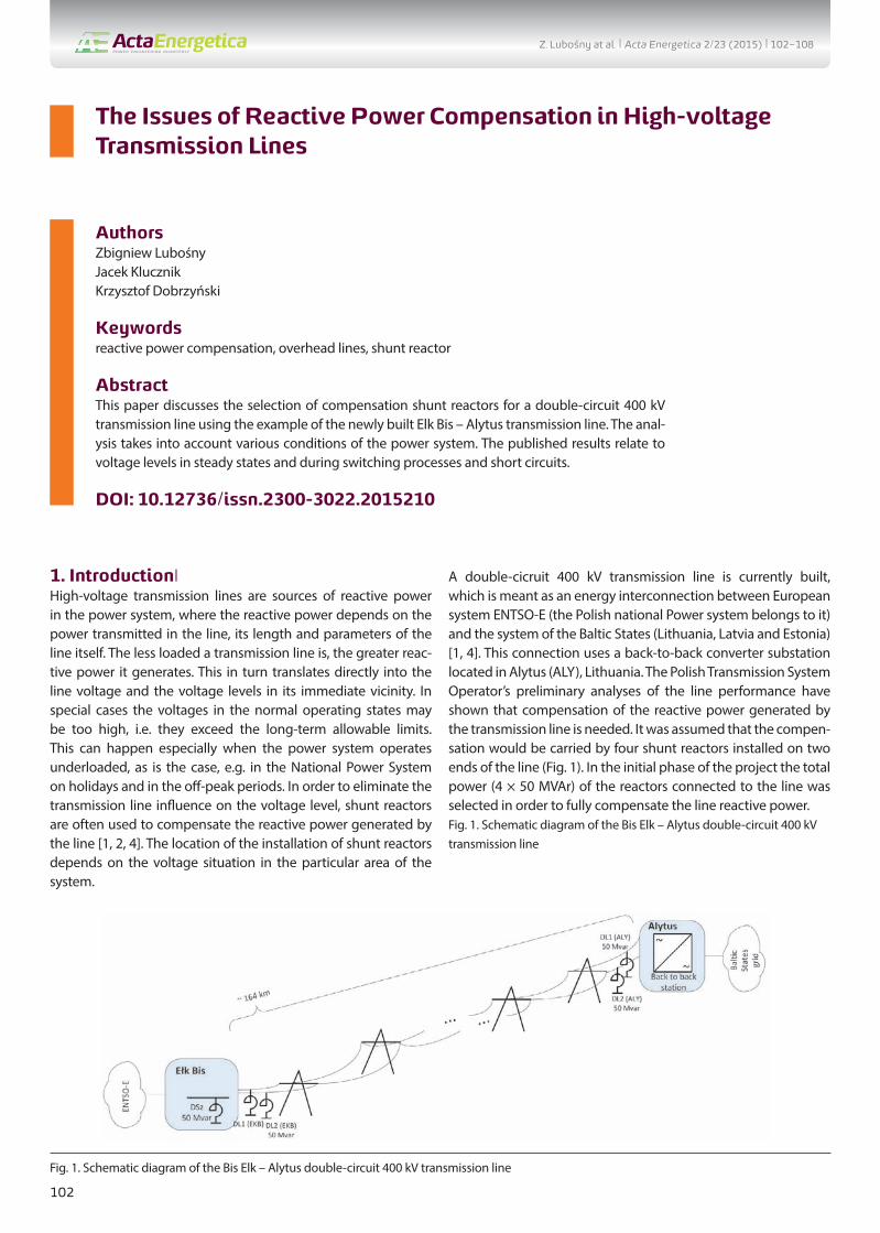
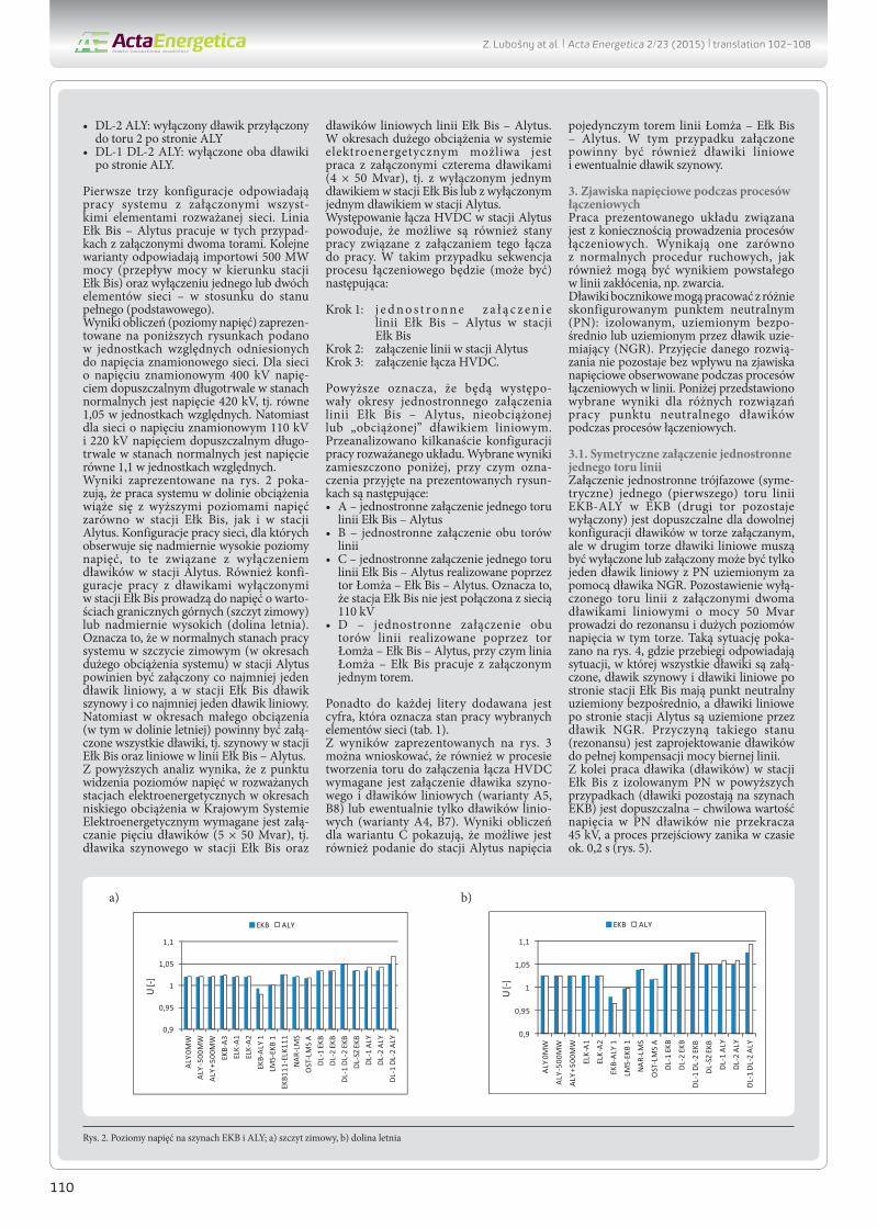
A double-cicruit 400 kV transmission line is currently built, which is meant as an energy interconnection between European system ENTSO-E (the Polish national Power system belongs to it) and the system of the Baltic States (Lithuania, Latvia and Estonia) [1, 4]. This connection uses a back-to-back converter substation located in Alytus (ALY), Lithuania. The Polish Transmission System Operator’s preliminary analyses of the line performance have shown that compensation of the reactive power generated by the transmission line is needed. It was assumed that the compen-sation would be carried by four shunt reactors installed on two ends of the line (Fig. 1). In the initial phase of the project the total power (4 × 50 MVAr) of the reactors connected to the line was selected in order to fully compensate the line reactive power.Fig. 1. Schematic diagram of the Bis Elk – Alytus double-circuit 400 kV transmission line
Fig. 1. Schematic diagram of the Bis Elk – Alytus double-circuit 400 kV transmission line
Z. Lubośny at al. | Acta Energetica 2/23 (2015) | 102–108
103
Besides the reactors directly connected to the line (DL1, DL2 in Fig.1), in Elk Bis (EKB) substation an additional bus reactor will be installed (DSz in Fig. 1), also with 50 MVAr capacity. The described system is intended to provide an active power interchange of ±500 MW in the initial stage of its operation. In the next stage, it is planned to transfer power up to ±1000 MW.
2. Line voltages in steady statesThe voltage conditions in steady states should be determined for various operating configurations of the circuit shown in Fig. 1, taking into account the possibility of grid components outages in the immediate vicinity of the considered transmission line. The following power grid configurations were analysed:• ALY 0 MW: no power transmitted through HVDC link• ALY -500 MW: export of 500 MW to Lithuania• ALY +500 MW: import of 500 MW from Lithuania• Tr EKB-A3: EKB-A3 transformer switched off (in Elk substation)• Tr ELK-A1: ELK-A1 transformer switched off (in Elk substation)• ELK-A2: ELK-A2 transformer switched off (in Elk substation)• EKB-ALY 1: circuit 1 of Elk Bis – Alytus transmission line
switched off• LMS-EKB 1: circuit 1 of Lomza – Elk Bis transmission line
switched off• EKB111-ELK111: EKB111-ELK111 transmission line switched off• NAR-LMS: Narew - Lomza line transmission switched off• OST-LMS A: circuit 1. of Ostroleka - Lomza transmission line
switched off• DL-1 EKB: line reactor connected to circuit 1 in EKB substation
switched off• DL-2 EKB: line reactor connected to circuit 2 in EKB substation
switched off• DL-1 DL-2 EKB: both line reactors in EKB substation switched off• DL-SZ EKB: bus reactor in EKB substation switched off• DL-1 ALY: line reactor connected to circuit 1 in ALY substation
switched off• DL-2 ALY: line reactor connected to circuit 2 in ALY substation
switched off• DL-1 DL-2 ALY: both line reactors in ALY substation switched off
The first three configurations correspond to the system opera-tion with all components of the analysed grid energized. In these cases the Elk Bis – Alytus transmission line operates with both its circuits switched on. Further variants correspond to the import of 500 MW (power flow towards Elk Bis substation) and one or two grid components switched off – as compared to the complete (basic) condition.
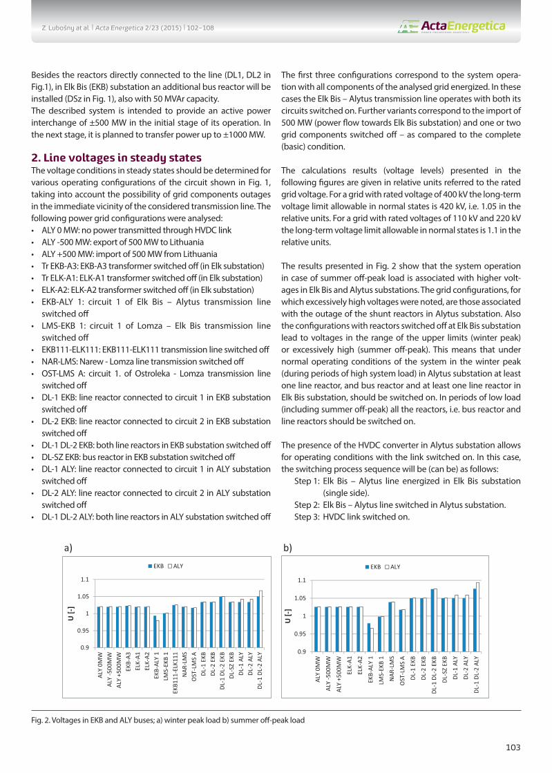
The calculations results (voltage levels) presented in the following figures are given in relative units referred to the rated grid voltage. For a grid with rated voltage of 400 kV the long-term voltage limit allowable in normal states is 420 kV, i.e. 1.05 in the relative units. For a grid with rated voltages of 110 kV and 220 kV the long-term voltage limit allowable in normal states is 1.1 in the relative units.
The results presented in Fig. 2 show that the system operation in case of summer off-peak load is associated with higher volt-ages in Elk Bis and Alytus substations. The grid configurations, for which excessively high voltages were noted, are those associated with the outage of the shunt reactors in Alytus substation. Also the configurations with reactors switched off at Elk Bis substation lead to voltages in the range of the upper limits (winter peak) or excessively high (summer off-peak). This means that under normal operating conditions of the system in the winter peak (during periods of high system load) in Alytus substation at least one line reactor, and bus reactor and at least one line reactor in Elk Bis substation, should be switched on. In periods of low load (including summer off-peak) all the reactors, i.e. bus reactor and line reactors should be switched on.
The presence of the HVDC converter in Alytus substation allows for operating conditions with the link switched on. In this case, the switching process sequence will be (can be) as follows:
Step 1: Elk Bis – Alytus line energized in Elk Bis substation (single side).
Step 2: Elk Bis – Alytus line switched in Alytus substation.Step 3: HVDC link switched on.
Fig. 2. Voltages in EKB and ALY buses; a) winter peak load b) summer off-peak load
Z. Lubośny at al. | Acta Energetica 2/23 (2015) | 102–108
104
This means that there will be periods when single side of Elk Bis – Alytus transmission line is switched on, and line operates unloaded or loaded only by line reactor. A dozen or so operating configurations of the system were analysed. Selected results are given below, and the following designations were adopted for the presented drawings:A – one circuit of Elk Bis – Alytus line is energized (line switched
on only in Elk Bis substation) B – both circuits of the line are energized (line switched on only
in Elk Bis substation)C – one circuit of Elk Bis-Alytus line is energized through Lomza
– Elk Bis line. This means that Elk Bis substation is not connected to the 110 kV grid.
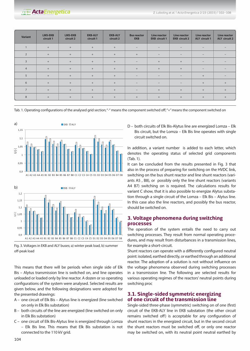
D – both circuits of Elk Bis-Alytus line are energized Lomza – Elk Bis circuit, but the Lomza – Elk Bis line operates with single circuit switched on.
In addition, a variant number is added to each letter, which denotes the operating status of selected grid components (Tab. 1).It can be concluded from the results presented in Fig. 3 that also in the process of preparing for switching on the HVDC link, switching on the bus shunt reactor and line shunt reactors (vari-ants A5 , B8), or possibly only the line shunt reactors (variants A4 B7) switching on is required. The calculations results for variant C show, that it is also possible to energize Alytus substa-tion through a single circuit of the Lomza – Elk Bis – Alytus line. In this case also the line reactors, and possibly the bus reactor, should be switched on.
3. Voltage phenomena during switching processesThe operation of the system entails the need to carry out switching processes. They result from normal operating proce-dures, and may result from disturbances in a transmission lines, for example a short-circuit.Shunt reactors can operate with a differently configured neutral point: isolated, earthed directly, or earthed through an additional reactor. The adoption of a solution is not without influence on the voltage phenomena observed during switching processes in a transmission line. The following are selected results for various operating regimes of the reactors’ neutral points during switching proc
3.1. Single-sided symmetric energizing of one circuit of the transmission lineSingle-sided three-phase (symmetric) switching on of one (first) circuit of the EKB-ALY line in EKB substation (the other circuit remains switched off) is acceptable for any configuration of shunt reactors in the energized circuit, but in the second circuit the shunt reactors must be switched off, or only one reactor may be switched on, with its neutral point neutral earthed by
a)
b)
Fig. 3. Voltages in EKB and ALY buses; a) winter peak load, b) summer off-peak load
Tab. 1. Operating configurations of the analysed grid section; “-“ means the component switched off; “+” means the component switched on
Z. Lubośny at al. | Acta Energetica 2/23 (2015) | 102–108
105
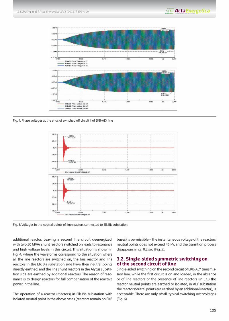
additional reactor. Leaving a second line circuit deenergized, with two 50 MVAr shunt reactors switched on leads to resonance and high voltage levels in this circuit. This situation is shown in Fig. 4, where the waveforms correspond to the situation where all the line reactors are switched on, the bus reactor and line reactors in the Elk Bis substation side have their neutral points directly earthed, and the line shunt reactors in the Alytus substa-tion side are earthed by additional reactors. The reason of reso-nance is to design reactors for full compensation of the reactive power in the line.
The operation of a reactor (reactors) in Elk Bis substation with isolated neutral point in the above cases (reactors remain on EKB
buses) is permissible – the instantaneous voltage of the reactors’ neutral points does not exceed 45 kV, and the transition process disappears in ca. 0.2 sec (Fig. 5).
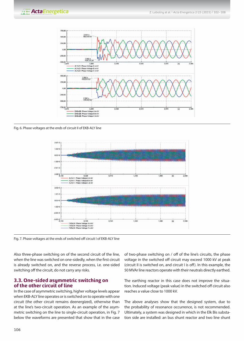
3.2. Single-sided symmetric switching on of the second circuit of lineSingle-sided switching on the second circuit of EKB-ALY transmis-sion line, while the first circuit is on and loaded, in the absence or of line reactors or the presence of line reactors (in EKB the reactor neutral points are earthed or isolated, in ALY substation the reactor neutral points are earthed by an additional reactor), is acceptable. There are only small, typical switching overvoltages (Fig. 6).
Fig. 4. Phase voltages at the ends of switched off circuit II of EKB-ALY line
Fig. 5. Voltages in the neutral points of line reactors connected to Elk Bis substation
Z. Lubośny at al. | Acta Energetica 2/23 (2015) | 102–108
106
Also three-phase switching on of the second circuit of the line, when the line was switched on one-sidedly, when the first circuit is already switched on, and the reverse process, i.e. one-sided switching off the circuit, do not carry any risks.
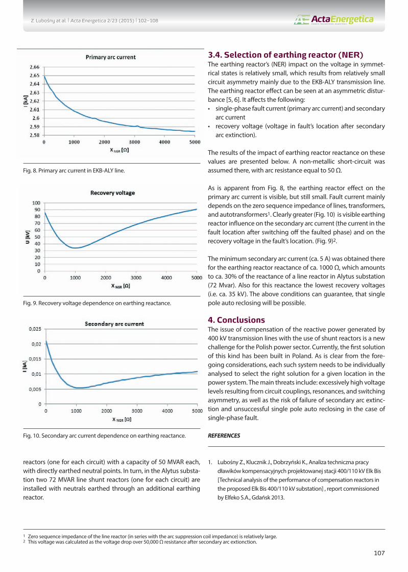
3.3. One-sided asymmetric switching on of the other circuit of lineIn the case of asymmetric switching, higher voltage levels appear when EKB-ALY line operates or is switched on to operate with one circuit (the other circuit remains deenergized), otherwise than at the line’s two-circuit operation. As an example of the asym-metric switching on the line to single-circuit operation, in Fig. 7 below the waveforms are presented that show that in the case
of two-phase switching on / off of the line’s circuits, the phase voltage in the switched off circuit may exceed 1000 kV at peak (circuit II is switched on, and circuit I is off). In this example, the 50 MVAr line reactors operate with their neutrals directly earthed.
The earthing reactor in this case does not improve the situa-tion. Induced voltage (peak value) in the switched off circuit also reaches a value close to 1000 kV.
The above analyses show that the designed system, due to the probability of resonance occurrence, is not recommended. Ultimately, a system was designed in which in the Elk Bis substa-tion side are installed: an bus shunt reactor and two line shunt
Fig. 6. Phase voltages at the ends of circuit II of EKB-ALY line
Fig. 7. Phase voltages at the ends of switched off circuit I of EKB-ALY line
Z. Lubośny at al. | Acta Energetica 2/23 (2015) | 102–108
107
reactors (one for each circuit) with a capacity of 50 MVAR each, with directly earthed neutral points. In turn, in the Alytus substa-tion two 72 MVAR line shunt reactors (one for each circuit) are installed with neutrals earthed through an additional earthing reactor.
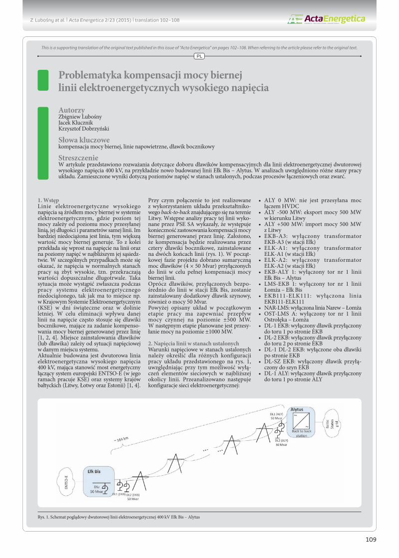
3.4. Selection of earthing reactor (NER)The earthing reactor’s (NER) impact on the voltage in symmet-rical states is relatively small, which results from relatively small circuit asymmetry mainly due to the EKB-ALY transmission line. The earthing reactor effect can be seen at an asymmetric distur-bance [5, 6]. It affects the following:• single-phase fault current (primary arc current) and secondary
arc current• recovery voltage (voltage in fault’s location after secondary
arc extinction).
The results of the impact of earthing reactor reactance on these values are presented below. A non-metallic short-circuit was assumed there, with arc resistance equal to 50 Ω.
As is apparent from Fig. 8, the earthing reactor effect on the primary arc current is visible, but still small. Fault current mainly depends on the zero sequence impedance of lines, transformers, and autotransformers1. Clearly greater (Fig. 10) is visible earthing reactor influence on the secondary arc current (the current in the fault location after switching off the faulted phase) and on the recovery voltage in the fault’s location. (Fig. 9)2.
The minimum secondary arc current (ca. 5 A) was obtained there for the earthing reactor reactance of ca. 1000 Ω, which amounts to ca. 30% of the reactance of a line reactor in Alytus substation (72 Mvar). Also for this reactance the lowest recovery voltages (i.e. ca. 35 kV). The above conditions can guarantee, that single pole auto reclosing will be possible.
4. ConclusionsThe issue of compensation of the reactive power generated by 400 kV transmission lines with the use of shunt reactors is a new challenge for the Polish power sector. Currently, the first solution of this kind has been built in Poland. As is clear from the fore-going considerations, each such system needs to be individually analysed to select the right solution for a given location in the power system. The main threats include: excessively high voltage levels resulting from circuit couplings, resonances, and switching asymmetry, as well as the risk of failure of secondary arc extinc-tion and unsuccessful single pole auto reclosing in the case of single-phase fault.
REFERENCES
1. Lubośny Z., Klucznik J., Dobrzyński K., Analiza techniczna pracy dławików kompensacyjnych projektowanej stacji 400/110 kV Elk Bis [Technical analysis of the performance of compensation reactors in the proposed Elk Bis 400/110 kV substation] , report commissioned by Elfeko S.A., Gdańsk 2013.
Fig. 8. Primary arc current in EKB-ALY line.
Fig. 9. Recovery voltage dependence on earthing reactance.
Fig. 10. Secondary arc current dependence on earthing reactance.
1 Zero sequence impedance of the line reactor (in series with the arc suppression coil impedance) is relatively large.2 This voltage was calculated as the voltage drop over 50,000 Ω resistance after secondary arc extionction.
Z. Lubośny at al. | Acta Energetica 2/23 (2015) | 102–108
108
2. Klucznik J. et al., Case studies of resonance phenomena in high volt-age overhead power lines with shunt reactors, The Sixteenth Biennial IEEE Conference on Electromagnetic Field Computation CEFC 2014, France 2014.
3. Robak S., Wasilewski J., Analiza asymetrii napięć i prądów w układzie sieci elektroenergetycznego połączenia Polska – Litwa [Analysis of voltage and current asymmetry in the Poland-Lithuania interconnec-tion], Energetyka 2012, Vol. XXII.
4. Escudero M.V., Redfern M., Effects of Transmission Line Construction on Resonance in Shunt Compensated EHV Lines, IPST, Montreal, Canada, 2005, Paper No IPST05-109.
5. Klucznik J. et al., Evaluation of Single Pole Auto-Reclosing Effectiveness with Nonlinear Secondary Arc Model, XXIII Symposium Electromagnetic Phenomena in Nonlinear Circuit, Pilsen: University of West Bohemia, 2014, pp. 75–76.
6. Klucznik J. et al., Nonlinear secondary arc model use for evaluation of single pole auto-reclosing effectiveness, COMPEL2015, Vol. 34, No. 3.
Graduated from Gdańsk University of Technology. A professor of engineering since 2004. Currently an associate professor at Gdańsk University of Technology. His
areas of interest include mathematical modelling, power system stability, power system control, use of artificial intelligence application in power system control, and
modelling and control of wind turbines. Editor in Chief of Acta Energetica.
He graduated from the Faculty of Electrical and Control Engineering at Gdańsk University of Technology (1999). Five years later he obtained his Ph.D. An assistant
professor at the Power Engineering Department of his alma mater. His areas of interest include control systems for generators and turbines, wind power generation,
transmission lines and power system automatic protections.
Krzysztof DobrzyńskiGdańsk University of Technology
Graduated from the Faculty of Electrical Engineering of Warsaw University of Technology in 1999. In 2012 he obtained a PhD degree at the Faculty of Electrical and
Control Engineering of Gdańsk University of Technology. An assistant professor at the Power Engineering Department of Gdańsk University of Technology. His areas
of interest include cooperation of distributed generation sources with the power system, mathematical modelling, power system control, and intelligent systems in
buildings.
Z. Lubośny at al. | Acta Energetica 2/23 (2015) | 102–108
109
Problematyka kompensacji mocy biernej linii elektroenergetycznych wysokiego napięcia
Słowa kluczowekompensacja mocy biernej, linie napowietrzne, dławik bocznikowy
StreszczenieW artykule przedstawiono rozważania dotyczące doboru dławików kompensacyjnych dla linii elektroenergetycznej dwutorowej wysokiego napięcia 400 kV, na przykładzie nowo budowanej linii Ełk Bis – Alytus. W analizach uwzględniono różne stany pracy układu. Zamieszczone wyniki dotyczą poziomów napięć w stanach ustalonych, podczas procesów łączeniowych oraz zwarć.
1. WstępLinie elektroenergetyczne wysokiego napięcia są źródłem mocy biernej w systemie elektroenergetycznym, gdzie poziom tej mocy zależy od poziomu mocy przesyłanej linią, jej długości i parametrów samej linii. Im bardziej niedociążona jest linia, tym większą wartość mocy biernej generuje. To z kolei przekłada się wprost na napięcie na linii oraz na poziomy napięć w najbliższym jej sąsiedz-twie. W szczególnych przypadkach może się okazać, że napięcia w normalnych stanach pracy są zbyt wysokie, tzn. przekraczają wartości dopuszczalne długotrwale. Taka sytuacja może wystąpić zwłaszcza podczas pracy systemu elektroenergetycznego niedociążonego, tak jak ma to miejsce np. w Krajowym Systemie Elektroenergetycznym (KSE) w dni świąteczne oraz w dolinie letniej. W celu eliminacji wpływu danej linii na napięcie często stosuje się dławiki bocznikowe, mające za zadanie kompenso-wania mocy biernej generowanej przez linię [1, 2, 4]. Miejsce zainstalowania dławików (lub dławika) zależy od sytuacji napięciowej w danym miejscu systemu.Aktualnie budowana jest dwutorowa linia elektroenergetyczna wysokiego napięcia 400 kV, mająca stanowić most energetyczny łączący system europejski ENTSO-E (w jego ramach pracuje KSE) oraz systemy krajów bałtyckich (Litwy, Łotwy oraz Estonii) [1, 4].
Przy czym połączenie to jest realizowane z wykorzystaniem układu przekształtniko-wego back-to-back znajdującego się na terenie Litwy. Wstępne analizy pracy tej linii wyko-nane przez PSE SA wykazały, że występuje konieczność zastosowania kompensacji mocy biernej generowanej przez linię. Założono, że kompensacja będzie realizowana przez cztery dławiki bocznikowe, zainstalowane na dwóch końcach linii (rys. 1). W począt-kowej fazie projektu dobrano sumaryczną moc dławików (4 × 50 Mvar) przyłączonych do linii w celu pełnej kompensacji mocy biernej linii.Oprócz dławików, przyłączonych bezpo-średnio do linii w stacji Ełk Bis, zostanie zainstalowany dodatkowy dławik szynowy, również o mocy 50 Mvar. Powyżej opisany układ w początkowym etapie pracy ma zapewniać przepływ mocy czynnej na poziomie ±500 MW. W następnym etapie planowane jest przesy-łanie mocy na poziomie ±1000 MW.
2. Napięcia linii w stanach ustalonychWarunki napięciowe w stanach ustalonych należy określić dla różnych konfiguracji pracy układu przedstawionego na rys. 1, uwzględniając przy tym możliwość wyłą-czeń elementów sieciowych w najbliższej okolicy linii. Przeanalizowano następuje konfiguracje sieci elektroenergetycznej:
• ALY 0 MW: nie jest przesyłana moc łączem HVDC
• ALY -500 MW: eksport mocy 500 MW w kierunku Litwy
• ALY +500 MW: import mocy 500 MW z Litwy
• EKB-A3: wyłączony transformator EKB-A3 (w stacji Ełk)
• ELK-A1: wyłączony transformator ELK-A1 (w stacji Ełk)
• ELK-A2: wyłączony transformator ELK-A2 (w stacji Ełk)
• EKB-ALY 1: wyłączony tor nr 1 linii Ełk Bis – Alytus
• LMS-EKB 1: wyłączony tor nr 1 linii Łomża – Ełk Bis
• EKB111-ELK111: wyłączona linia EKB111-ELK111
• NAR-LMS: wyłączona linia Narew – Łomża• OST-LMS A: wyłączony tor nr 1 linii
do toru 1 po stronie EKB• DL-2 EKB: wyłączony dławik przyłączony
do toru 2 po stronie EKB• DL-1 DL-2 EKB: wyłączone oba dławiki
po stronie EKB• DL-SZ EKB: wyłączony dławik przyłą-
czony do szyn EKB• DL-1 ALY: wyłączony dławik przyłączony
do toru 1 po stronie ALY
PL
This is a supporting translation of the original text published in this issue of “Acta Energetica” on pages 102–108. When referring to the article please refer to the original text.
Rys. 1. Schemat poglądowy dwutorowej linii elektroenergetycznej 400 kV Ełk Bis – Alytus
Z. Lubośny at al. | Acta Energetica 2/23 (2015) | translation 102–108
110
• DL-2 ALY: wyłączony dławik przyłączony do toru 2 po stronie ALY
• DL-1 DL-2 ALY: wyłączone oba dławiki po stronie ALY.
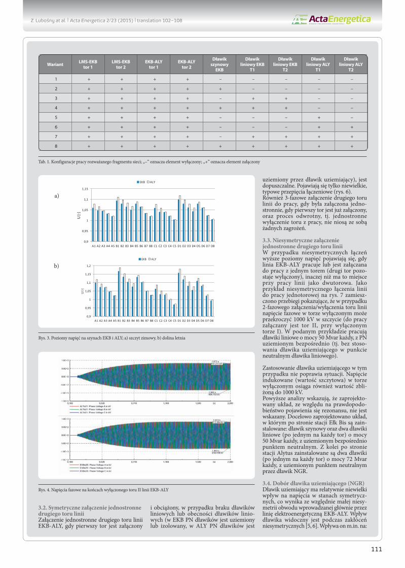
Pierwsze trzy konfiguracje odpowiadają pracy systemu z załączonymi wszyst-kimi elementami rozważanej sieci. Linia Ełk Bis – Alytus pracuje w tych przypad-kach z załączonymi dwoma torami. Kolejne warianty odpowiadają importowi 500 MW mocy (przepływ mocy w kierunku stacji Ełk Bis) oraz wyłączeniu jednego lub dwóch elementów sieci – w stosunku do stanu pełnego (podstawowego).Wyniki obliczeń (poziomy napięć) zaprezen-towane na poniższych rysunkach podano w jednostkach względnych odniesionych do napięcia znamionowego sieci. Dla sieci o napięciu znamionowym 400 kV napię-ciem dopuszczalnym długotrwale w stanach normalnych jest napięcie 420 kV, tj. równe 1,05 w jednostkach względnych. Natomiast dla sieci o napięciu znamionowym 110 kV i 220 kV napięciem dopuszczalnym długo-trwale w stanach normalnych jest napięcie równe 1,1 w jednostkach względnych.Wyniki zaprezentowane na rys. 2 poka-zują, że praca systemu w dolinie obciążenia wiąże się z wyższymi poziomami napięć zarówno w stacji Ełk Bis, jak i w stacji Alytus. Konfiguracje pracy sieci, dla których obserwuje się nadmiernie wysokie poziomy napięć, to te związane z wyłączeniem dławików w stacji Alytus. Również konfi-guracje pracy z dławikami wyłączonymi w stacji Ełk Bis prowadzą do napięć o warto-ściach granicznych górnych (szczyt zimowy) lub nadmiernie wysokich (dolina letnia). Oznacza to, że w normalnych stanach pracy systemu w szczycie zimowym (w okresach dużego obciążenia systemu) w stacji Alytus powinien być załączony co najmniej jeden dławik liniowy, a w stacji Ełk Bis dławik szynowy i co najmniej jeden dławik liniowy. Natomiast w okresach małego obciązenia (w tym w dolinie letniej) powinny być załą-czone wszystkie dławiki, tj. szynowy w stacji Ełk Bis oraz liniowe w linii Ełk Bis – Alytus.Z powyższych analiz wynika, że z punktu widzenia poziomów napięć w rozważanych stacjach elektroenergetycznych w okresach niskiego obciążenia w Krajowym Systemie Elektroenergetycznym wymagane jest załą-czanie pięciu dławików (5 × 50 Mvar), tj. dławika szynowego w stacji Ełk Bis oraz
dławików liniowych linii Ełk Bis – Alytus. W okresach dużego obciążenia w systemie elektroenergetycznym możliwa jest praca z załączonymi czterema dławikami (4 × 50 Mvar), tj. z wyłączonym jednym dławikiem w stacji Ełk Bis lub z wyłączonym jednym dławikiem w stacji Alytus.Występowanie łącza HVDC w stacji Alytus powoduje, że możliwe są również stany pracy związane z załączaniem tego łącza do pracy. W takim przypadku sekwencja procesu łączeniowego będzie (może być) następująca:
Krok 1: j e d n o s t r o n n e z a ł ą c z e n i e linii Ełk Bis – Alytus w stacji Ełk Bis
Krok 2: załączenie linii w stacji AlytusKrok 3: załączenie łącza HVDC.
Powyższe oznacza, że będą występo-wały okresy jednostronnego załączenia linii Ełk Bis – Alytus, nieobciążonej lub „obciążonej” dławikiem liniowym. Przeanalizowano kilkanaście konfiguracji pracy rozważanego układu. Wybrane wyniki zamieszczono poniżej, przy czym ozna-czenia przyjęte na prezentowanych rysun-kach są następujące:• A – jednostronne załączenie jednego toru
linii Ełk Bis – Alytus• B – jednostronne załączenie obu torów
linii• C – jednostronne załączenie jednego toru
linii Ełk Bis – Alytus realizowane poprzez tor Łomża – Ełk Bis – Alytus. Oznacza to, że stacja Ełk Bis nie jest połączona z siecią 110 kV
• D – jednostronne załączenie obu torów linii realizowane poprzez tor Łomża – Ełk Bis – Alytus, przy czym linia Łomża – Ełk Bis pracuje z załączonym jednym torem.
Ponadto do każdej litery dodawana jest cyfra, która oznacza stan pracy wybranych elementów sieci (tab. 1).Z wyników zaprezentowanych na rys. 3 można wnioskować, że również w procesie tworzenia toru do załączenia łącza HVDC wymagane jest załączenie dławika szyno-wego i dławików liniowych (warianty A5, B8) lub ewentualnie tylko dławików linio-wych (warianty A4, B7). Wyniki obliczeń dla wariantu C pokazują, że możliwe jest również podanie do stacji Alytus napięcia
pojedynczym torem linii Łomża – Ełk Bis – Alytus. W tym przypadku załączone powinny być również dławiki liniowe i ewentualnie dławik szynowy.
3. Zjawiska napięciowe podczas procesów łączeniowychPraca prezentowanego układu związana jest z koniecznością prowadzenia procesów łączeniowych. Wynikają one zarówno z normalnych procedur ruchowych, jak również mogą być wynikiem powstałego w linii zakłócenia, np. zwarcia.Dławiki bocznikowe mogą pracować z różnie skonfigurowanym punktem neutralnym (PN): izolowanym, uziemionym bezpo-średnio lub uziemionym przez dławik uzie-miający (NGR). Przyjęcie danego rozwią-zania nie pozostaje bez wpływu na zjawiska napięciowe obserwowane podczas procesów łączeniowych w linii. Poniżej przedstawiono wybrane wyniki dla różnych rozwiązań pracy punktu neutralnego dławików podczas procesów łączeniowych.
3.1. Symetryczne załączenie jednostronne jednego toru liniiZałączenie jednostronne trójfazowe (syme-tryczne) jednego (pierwszego) toru linii EKB-ALY w EKB (drugi tor pozostaje wyłączony) jest dopuszczalne dla dowolnej konfiguracji dławików w torze załączanym, ale w drugim torze dławiki liniowe muszą być wyłączone lub załączony może być tylko jeden dławik liniowy z PN uziemionym za pomocą dławika NGR. Pozostawienie wyłą-czonego toru linii z załączonymi dwoma dławikami liniowymi o mocy 50 Mvar prowadzi do rezonansu i dużych poziomów napięcia w tym torze. Taką sytuację poka-zano na rys. 4, gdzie przebiegi odpowiadają sytuacji, w której wszystkie dławiki są załą-czone, dławik szynowy i dławiki liniowe po stronie stacji Ełk Bis mają punkt neutralny uziemiony bezpośrednio, a dławiki liniowe po stronie stacji Alytus są uziemione przez dławik NGR. Przyczyną takiego stanu (rezonansu) jest zaprojektowanie dławików do pełnej kompensacji mocy biernej linii.Z kolei praca dławika (dławików) w stacji Ełk Bis z izolowanym PN w powyższych przypadkach (dławiki pozostają na szynach EKB) jest dopuszczalna – chwilowa wartość napięcia w PN dławików nie przekracza 45 kV, a proces przejściowy zanika w czasie ok. 0,2 s (rys. 5).
0,9
0,95
1
1,05
1,1
ALY 0
MW
ALY -
500M
W
ALY +
500M
W
ELK-
A1
ELK-
A2
EKB-
ALY
1
LMS-
EKB
1
NAR-
LMS
OST
-LM
S A
DL-1
EKB
DL-2
EKB
DL-1
DL-
2 EK
B
DL-S
Z EKB
DL-1
ALY
DL-2
ALY
DL-1
DL-
2 AL
Y
U [-
]
EKB ALY
a) b)
Rys. 2. Poziomy napięć na szynach EKB i ALY; a) szczyt zimowy, b) dolina letnia
Z. Lubośny at al. | Acta Energetica 2/23 (2015) | translation 102–108
111
3.2. Symetryczne załączenie jednostronne drugiego toru liniiZałączenie jednostronne drugiego toru linii EKB-ALY, gdy pierwszy tor jest załączony
i obciążony, w przypadku braku dławików liniowych lub obecności dławików linio-wych (w EKB PN dławików jest uziemiony lub izolowany, w ALY PN dławików jest
uziemiony przez dławik uziemiający), jest dopuszczalne. Pojawiają się tylko niewielkie, typowe przepięcia łączeniowe (rys. 6).Również 3-fazowe załączenie drugiego toru linii do pracy, gdy była załączona jedno-stronnie, gdy pierwszy tor jest już załączony, oraz proces odwrotny, tj. jednostronne wyłączenie toru z pracy, nie niosą ze sobą żadnych zagrożeń.
3.3. Niesymetryczne załączenie jednostronne drugiego toru liniiW przypadku niesymetrycznych łączeń wyższe poziomy napięć pojawiają się, gdy linia EKB-ALY pracuje lub jest załączana do pracy z jednym torem (drugi tor pozo-staje wyłączony), inaczej niż ma to miejsce przy pracy linii jako dwutorowa. Jako przykład niesymetrycznego łączenia linii do pracy jednotorowej na rys. 7 zamiesz-czono przebiegi pokazujące, że w przypadku 2-fazowego załączenia/wyłączenia toru linii napięcie fazowe w torze wyłączonym może przekroczyć 1000 kV w szczycie (do pracy załączany jest tor II, przy wyłączonym torze I). W podanym przykładzie pracują dławiki liniowe o mocy 50 Mvar każdy, z PN uziemionym bezpośrednio (tj. bez stoso-wania dławika uziemiającego w punkcie neutralnym dławika liniowego).
Zastosowanie dławika uziemiającego w tym przypadku nie poprawia sytuacji. Napięcie indukowane (wartość szczytowa) w torze wyłączonym osiąga również wartość zbli-żoną do 1000 kV.Powyższe analizy wskazują, że zaprojekto-wany układ, ze względu na prawdopodo-bieństwo pojawienia się rezonansu, nie jest wskazany. Docelowo zaprojektowano układ, w którym po stronie stacji Ełk Bis są zain-stalowane: dławik szynowy oraz dwa dławiki liniowe (po jednym na każdy tor) o mocy 50 Mvar każdy, z uziemionym bezpośrednio punktem neutralnym. Z kolei po stronie stacji Alytus zainstalowane są dwa dławiki (po jednym na każdy tor) o mocy 72 Mvar każdy, z uziemionym punktem neutralnym przez dławik NGR.
3.4. Dobór dławika uziemiającego (NGR)Dławik uziemiający ma relatywnie niewielki wpływ na napięcia w stanach symetrycz-nych, co wynika ze względnie małej niesy-metrii obwodu wprowadzanej głównie przez linię elektroenergetyczną EKB-ALY. Wpływ dławika widoczny jest podczas zakłóceń niesymetrycznych [5, 6]. Wpływa on m.in. na:
Tab. 1. Konfiguracje pracy rozważanego fragmentu sieci; „–” oznacza element wyłączony; „+” oznacza element załączony
Rys. 3. Poziomy napięć na szynach EKB i ALY; a) szczyt zimowy, b) dolina letnia
Rys. 4. Napięcia fazowe na końcach wyłączonego toru II linii EKB-ALY
a)
b)
Z. Lubośny at al. | Acta Energetica 2/23 (2015) | translation 102–108
112
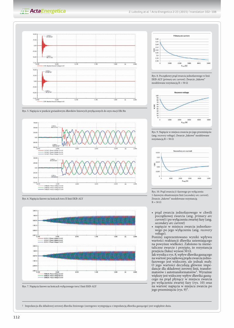
• prąd zwarcia jednofazowego w chwili początkowej zwarcia (ang. primary arc current) i po wyłączeniu zwartej fazy (ang. secondary arc current)
• napięcie w miejscu zwarcia jednofazo-wego po jego wyłączeniu (ang. recovery voltage).
Poniżej zaprezentowano wyniki wpływu wartości reaktancji dławika uziemiającego na powyższe wielkości. Założono tu nieme-taliczne zwarcie i przyjęto, że rezystancja przejścia (łuku) wynosi 50 Ω.Jak wynika z rys. 8, wpływ dławika gaszącego na wartość początkową prądu zwarcia jedno-fazowego jest widoczny, ale jednak mały. O jego wartości decydują głównie impe-dancje dla składowej zerowej linii, transfor-matorów i autotransformatorów1. Wyraźnie większy jest widoczny wpływ dławika gaszą-cego na prąd płynący w miejscu zwarcia po wyłączeniu zwartej fazy (rys. 10) oraz na wartość napięcia w miejscu zwarcia po jego przeminięciu (rys. 9)2.
Rys. 5. Napięcia w punkcie gwiazdowym dławików liniowych przyłączonych do szyn stacji Ełk Bis
Rys. 8. Początkowy prąd zwarcia jednofazowego w linii EKB-ALY (primary arc current). Zwarcie „łukowe” modelowane rezystancją R = 50 Ω
Rys. 9. Napięcie w miejscu zwarcia po jego przeminięciu (ang. recovery voltage). Zwarcie „łukowe” modelowane rezystancją R = 50 Ω
Rys. 10. Prąd zwarcia j1-fazowego po wyłączeniu 1-fazowym obustronnym linii (secondary arc current). Zwarcie „łukowe” modelowane rezystancją R = 50 Ω
Rys. 6. Napięcia fazowe na końcach toru II linii EKB-ALY
Rys. 7. Napięcia fazowe na końcach wyłączonego toru I linii EKB-ALY
2 Impedancja dla składowej zerowej dławika liniowego (szeregowo występująca z impedancją dławika gaszącego) jest względnie duża.
Z. Lubośny at al. | Acta Energetica 2/23 (2015) | translation 102–108
113
Minimalną wartość prądu (rzędu 5 A) uzyskuje się tu dla impedancji dławika gaszącego równej ok. 1000 Ω, co stanowi około 30% impedancji dławika liniowego w stacji Alytus (72 Mvar). Również dla tej wartości impedancji dławika gaszą-cego uzyskuje się najmniejsze wartości napięcia po przeminięciu zwarcia (tj. równe ok. 35 kV).
4. PodsumowanieProblematyka kompensacji mocy biernej generowanej przez linie wysokiego napięcia 400 kV z wykorzystaniem dławików boczni-kowych jest dla krajowej energetyki nowym wyzwaniem. Aktualnie budowane jest pierwsze tego typu rozwiązanie w Polsce. Jak wynika z powyższych rozważań, tego typu układy każdorazowo wymagają analizy, która pozwoli dobrać odpowiedni układ do danego miejsca w systemie
elektroenergetycznym. Podstawowym zagrożeniem są tu: nadmiernie wysokie poziomy napięć wynikające ze sprzężeń, rezonansów, niesymetrii łączeń, a także zagrożenie niezgaszeniem się łuku wtórnego w przypadku zwarcia 1-fazowego.
Bibliografia1. Lubośny Z., Klucznik J., Dobrzyński K.,
Analiza techniczna pracy dławików kompensacyjnych projektowanej stacji 400/110 kV Ełk bis, raport dla Elfeko S.A., Gdańsk 2013.
2. Czapp S. i in., Case studies of resonance phenomena in high voltage overhead power lines with shunt reactors, The Sixteenth Biennial IEEE Conference on Electromagnetic Field Computation CEFC 2014, Francja 2014.
3. Robak S., Wasilewski J., Analiza asymetrii napięć i prądów w układzie sieci elektro-energetycznego połączenia Polska – Litwa, Energetyka 2012, Vol. XXII.
4. Escudero M.V., Redfern M., Effects of Transmission Line Construction on Resonance in Shunt Compensated EHV Lines, IPST, Montreal, Canada, 2005, Paper No IPST05-109.
5. Klucznik J. i in., Evaluation Of Single Pole Auto-Reclosing Effectiveness With Nonlinear Secondary Arc Model, XXIII Symposium Electromagnetic Phenomena in Nonlinear Circuit, Pilsen: University of West Bohemia, 2014, s. 75–76.
6. Klucznik J. i in., Nonlinear secon-dary arc model use for evaluation of single pole auto-reclosing effectiveness, COMPEL2015, Vol. 34, No. 4.
2 Napięcie to obliczano jako napięcie na rezystancji 50 000 Ω włączonej jednofazowo w miejscu zwarcia, po przeminięciu zwarcia.
Zbigniew Lubośny prof. dr hab. inż.Politechnika Gdańskae-mail: [email protected] Politechniki Gdańskiej. Od 2004 roku jest profesorem nauk technicznych. Obecnie zatrudniony na swojej macierzystej uczelni na stanowisku profesora. Obszar zainteresowań to: modelowanie matematyczne, stabilność systemu elektroenergetycznego, sterowanie systemem elektroenergetycznym, zastosowanie sztucznej inteligencji do sterowania systemem elektroenergetycznym, modelowanie i sterowanie elektrowniami wiatrowymi. Redaktor naczelny Acta Energetica.
Jacek Klucznik dr inż.Politechnika Gdańskae-mail: [email protected] magisterskie ukończył na Wydziale Elektrotechniki i Automatyki Politechniki Gdańskiej (1999). Pięć lat później uzyskał tytuł doktorski. Pracuje jako adiunkt w Katedrze Elektroenergetyki swojej macierzystej uczelni. Zajmuje się układami regulacji generatorów i turbin, energetyką wiatrową oraz elektroener-getyczną automatyką zabezpieczeniową.
Krzysztof Dobrzyńskidr inż. Politechnika Gdańskae-mail: [email protected]ńczył studia na Wydziale Elektrycznym Politechniki Warszawskiej w 1999 roku. W roku 2012 roku uzyskał tytuł doktorski na Wydziale Elektrotechniki i Automatyki Politechniki Gdańskiej. Pracuje jako adiunkt w Katedrze Elektroenergetyki Politechniki Gdańskiej. Obszar zainteresowań to współpraca źródeł generacji rozproszonej z systemem elektroenergetycznym, modelowanie matematyczne, sterowanie systemem elektroenergetycznym, instalacje inteligentne w budynkach.
Z. Lubośny at al. | Acta Energetica 2/23 (2015) | translation 102–108


![Reactive Power Compensation[1]](https://static.documents.pub/doc/80x56/577ccf3f1a28ab9e788f40c0/reactive-power-compensation1.jpg)


