مرشحات –محركات الديزل " ١٦٣٣٢/٢٠٠٦ تي إسم آيزوالمواصفة القياسية الدولية رق
" المنظمة الدولية للتقييس" والتي أصدرتها – “ طريقة تقييم كفاءة فصل الماء عن الوقود-الوقود
. العربية السعودية بإعداد مشروع هذه المواصفةة وقامت المملكوتمت ترجمتها باللغة العربية ،
وذلك في كمواصفة قياسية خليجية دون إدخال أية تعديالت فنية عليها وقد اعتمدت هذه المواصفة
هـ ، / / ، الذي عقد بتاريخ ( ) اجتماع مجلس إدارة الهيئة رقم
.م/ / الموافق
Foreword
GCC Standardization Organization (GSO) is a regional Organization which consists of the National Standards Bodies of GCC member States. One of GSO main functions is to issue Gulf Standards through specialized technical committees (TCs). GSO through the technical program of committee TC No.2-1: " The Gulf technical Subcommittee for vehicles and tyres standards” has adopted the International Standard No. : ISO TS 16332:2006 “Diesel engines – Fuel filter – Method for evaluating fuel/water separation efficiency " issued by International Organization for Standardization which has been translated into Arabic. The Draft Standard has been prepared by Kingdom of Saudi Arabia This standard has been approved as Gulf Standard without any technical modifications by GSO Board of Directors in its meeting No..../.... …….held on / / / H , / / G
Moteurs diesels — Filtres à carburant — Méthode d'évaluation de l'efficacité des séparateurs carburant-eau
ISO/TS 16332:2006(E)
PDF disclaimer This PDF file may contain embedded typefaces. In accordance with Adobe's licensing policy, this file may be printed or viewed but shall not be edited unless the typefaces which are embedded are licensed to and installed on the computer performing the editing. In downloading this file, parties accept therein the responsibility of not infringing Adobe's licensing policy. The ISO Central Secretariat accepts no liability in this area.
Adobe is a trademark of Adobe Systems Incorporated.
Details of the software products used to create this PDF file can be found in the General Info relative to the file; the PDF-creation parameters were optimized for printing. Every care has been taken to ensure that the file is suitable for use by ISO member bodies. In the unlikely event that a problem relating to it is found, please inform the Central Secretariat at the address given below.
Foreword............................................................................................................................................................ iv Introduction ........................................................................................................................................................ v 1 Scope ..................................................................................................................................................... 1 2 Normative references ........................................................................................................................... 1 3 Terms and definitions........................................................................................................................... 1 4 Symbols ................................................................................................................................................. 2 5 Test equipment ..................................................................................................................................... 2 5.1 Test fluids .............................................................................................................................................. 2 5.1.1 Test fuels ............................................................................................................................................... 2 5.1.2 Test water .............................................................................................................................................. 3 5.2 Laboratory equipment .......................................................................................................................... 3 5.2.1 High-speed mixer.................................................................................................................................. 3 5.3 Test stand .............................................................................................................................................. 3 5.3.1 Filter test circuit (see Figure 1) ........................................................................................................... 4 6 Test conditions ..................................................................................................................................... 6 6.1 Volume of fuel ....................................................................................................................................... 6 6.2 Test temperature T................................................................................................................................ 6 6.3 Test flow rate QT ................................................................................................................................... 7 6.4 Water concentration (undissolved water) .......................................................................................... 7 6.5 Differential pressure ∆pO across water emulsifying device (orifice plate) ..................................... 7 6.6 Total test duration ttotal ......................................................................................................................... 7
7 Accuracy of measuring instruments and test conditions ................................................................ 7 8 Validation procedure ............................................................................................................................ 8 8.1 Test stand .............................................................................................................................................. 8 8.2 Sampling procedure ............................................................................................................................. 9 8.2.1 Primary sampling procedure ............................................................................................................... 9 8.2.2 Secondary sampling procedure .......................................................................................................... 9 8.2.3 Secondary sampling procedure validation ........................................................................................ 9 9 Test procedure .................................................................................................................................... 10 9.1 Pre-test preparation............................................................................................................................ 10 9.2 Efficiency measurement .................................................................................................................... 10 10 Calculation and reporting of test results.......................................................................................... 11 10.1 Calculation of water separation efficiency....................................................................................... 11 10.2 Test report ........................................................................................................................................... 12 Annex A (normative) Water emulsifying device............................................................................................ 13 Annex B (normative) Procedure to determine the water droplet size distribution (DSD) ........................ 16 Annex C (informative) Typical filter test report ............................................................................................. 21 Annex D (informative) Selection of the specified average water droplet sizes D50 .................................. 23
ISO (the International Organization for Standardization) is a worldwide federation of national standards bodies (ISO member bodies). The work of preparing International Standards is normally carried out through ISO technical committees. Each member body interested in a subject for which a technical committee has been established has the right to be represented on that committee. International organizations, governmental and non-governmental, in liaison with ISO, also take part in the work. ISO collaborates closely with the International Electrotechnical Commission (IEC) on all matters of electrotechnical standardization.
International Standards are drafted in accordance with the rules given in the ISO/IEC Directives, Part 2.
The main task of technical committees is to prepare International Standards. Draft International Standards adopted by the technical committees are circulated to the member bodies for voting. Publication as an International Standard requires approval by at least 75 % of the member bodies casting a vote.
In other circumstances, particularly when there is an urgent market requirement for such documents, a technical committee may decide to publish other types of normative document:
— an ISO Publicly Available Specification (ISO/PAS) represents an agreement between technical experts in an ISO working group and is accepted for publication if it is approved by more than 50 % of the members of the parent committee casting a vote;
— an ISO Technical Specification (ISO/TS) represents an agreement between the members of a technical committee and is accepted for publication if it is approved by 2/3 of the members of the committee casting a vote.
An ISO/PAS or ISO/TS is reviewed after three years in order to decide whether it will be confirmed for a further three years, revised to become an International Standard, or withdrawn. If the ISO/PAS or ISO/TS is confirmed, it is reviewed again after a further three years, at which time it must either be transformed into an International Standard or be withdrawn.
Attention is drawn to the possibility that some of the elements of this document may be the subject of patent rights. ISO shall not be held responsible for identifying any or all such patent rights.
ISO/TS 16332 was prepared by Technical Committee ISO/TC 22, Road vehicles, Subcommittee SC 7, Injection equipment and filters for use on road vehicles.
Annexes A and B form normative parts of this Technical Specification. Annexes C and D are for information only.
Modern fuel injection systems, installed in passenger cars, as well as in heavy duty or off-road vehicle applications, require high and stable separation efficiencies for all insoluble contaminants in the fuel to ensure a prolonged life. Beside solid contamination, undissolved water, in finely or coarsely emulsified form, can also reduce the lifetime of injection systems. Suitable fuel filters, having a high level water separation efficiency, are an absolute necessity for system longevity.
Factors found to affect the separation efficiency of undissolved water in the field are mainly due to the fuel quality, which is strongly influenced by the performance of additives in the fuel itself, as well as the actual characteristics of the fuel/water-emulsion, the specific flow rate of the system, the type of media in the filter element, as well as the size and design of the filter housing itself. To ensure laboratory test results are comparable, these various parameters have to be taken into account in the test method, in order to reduce their influence on the test results.
NOTE A variety of tests were investigated prior and parallel to the preparation of this Technical Specification to specify the required test conditions. Additional work is underway to validate, confirm and if necessary to modify the following parameters:
⎯ test fuel (5.1.1);
⎯ water concentration of 1 500 ppm (6.4);
⎯ volume of fuel (6.1);
⎯ total test duration ttotal (6.6).
At the time of publication of this Technical Specification, interlaboratory tests are being organized to establish the repeatability and reproducibility of the results.
This Technical Specification specifies a fuel/water separation test with continuous water injection, using an offline water concentration measuring method, for evaluating the ability of a fuel filter to separate either finely or coarsely dispersed undissolved water out of fuel. This test is intended for application to filter elements which are installed upstream or downstream of the low pressure pump, having a rated flow (in litres per hour) between 50 l/h and 900 l/h. By agreement between customer and filter manufacturer, and with some modification, the procedure may be used for fuel filters with higher flow rates.
2 Normative references
The following referenced documents are indispensable for the application of this document. For dated references, only the edition cited applies. For undated references, the latest edition of the referenced document (including any amendments) applies.
ISO 760, Determination of water — Karl Fischer method (General method)
ISO 1219-1, Fluid power systems and components — Graphic symbols and circuit diagrams — Part 1: Graphic symbols for conventional use and data-processing applications
ISO 6889, Surface active agents — Determination of interfacial tension by drawing up liquid films
ISO 13320-1, Particle size analysis — Laser diffraction methods — Part 1: General principles
ASTM D 1401, Standard Test Method for Water Separability of Petroleum Oils and Synthetic Fluids
For the purposes of this document, the following terms and definitions apply.
3.1 interfacial tension IFT force required to increase the surface area of the interface between two liquids by a unit amount
NOTE Interfacial tension is expressed in millinewtons per metre (mN/m).
1) The reference fuel specification is provided by CEC secretariat services: Interlynk Administrative Services Ltd., PO Box 6475, Earl Shilton, Leicester LE9 9ZB, UK; T +44(0)1455 21993; F +44(0)1455 821994.
3.2 droplet size distribution DSD curve of the percentage of the droplet population in different size ranges
See Figure B.1.
3.3 base water concentration concentration of water in water saturated fuel
3.4 undissolved water difference between total and base water concentration
3.5 test time t “point of time” when a test or a measurement is started or running respectively
NOTE In contrast to the total test duration ttotal, see 6.6.
4 Symbols
Graphical symbols used in this Technical Specification for fluid power system components are in accordance with ISO 1219-1.
5 Test equipment
5.1 Test fluids
5.1.1 Test fuels
The test fuel shall be according to CEC RF-06-03 2) and processed to achieve the following requirements by adding a multifunctional fuel additive (see Note 1):
a) IFT
15 mN/m ± 3 mN/m measured according to ISO 6889 after 60 s;
b) water separability
270 s ± 30 s, when 75 % of test fuel is separated (sedimentation test according to ASTM D 1401 at 25 °C). Within this document, the water separability is defined through the point of time, when 75 % of the test fuel is separated.
NOTE 1 Fundamental tests lead to a mass fraction of approximately 0,1 % of the multifunctional fuel additive HiTEC 4620 2) to reach the required values.
The test fuel shall be stored protected from humidity, dust and light.
The batch of test fuel shall be changed when the fuel no longer meets the specified requirements.
2) Suitable products are available commercially. Details may be obtained from the Secretariat of Technical Committee ISO/TC22 or from the ISO Central Secretariat.
Optionally, if agreed between customer and filter manufacturer, the test can be performed with a fuel used in the application, but the deviations of the relevant fuel parameters shall be recorded in the test report.
NOTE 2 By using other fuel qualities (e.g. fuels used in application), the test results may not be comparable with the results obtained with the test fuel according to 5.1.1.
5.1.2 Test water
Clean, distilled, or deionized water with a surface tension of at least 70 mN/m, measured at 20 °C ± 1,5 °C.
5.2 Laboratory equipment
5.2.1 General
All laboratory equipment and glassware, required to determine the water concentration, shall be according to ISO 760.
5.2.2 Sampling bottles and glassware, 100 ml sampling bottles with 45 mm screw caps carefully rinsed with clean petroleum ether and dried in an oven.
5.2.3 Karl Fischer titration system 3), as commercially available and validated according to 8.2.3.
Recommended equipment should be composed of a coulometric, diaphragmless titration cell and a codistillation unit.
Humidity is probably the largest source of error during the titration process. Special precautions should be taken during setup and testing. The recommended amount of water per sample should be W 50 µg to reach a good relation between titration time and accuracy.
5.2.4 Analytical balance, with an accuracy of ± 1 mg.
5.2.5 Sampling syringe, with a volume of 1 ml ± 0,1 ml.
5.2.6 High-speed mixer
Mixer of the ULTRA-TURRAX type 3) with
⎯ a stator of 18 mm ± 1 mm,
⎯ a rotor of 12,5 mm ± 1 mm, and
⎯ a rotational speed of 15 000 min−1 ± 500 min−1.
5.3 Test stand
5.3.1 General
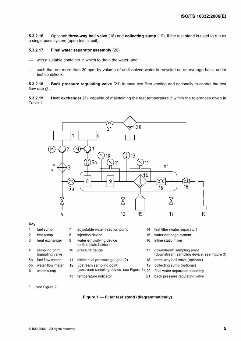
The test stand, shown diagrammatically in Figure 1, shall comprise a filter test circuit as described in 5.3.2.
3) This equipment has been found satisfactory. This information is given for the convenience of users of this Technical Specification and does not constitute an endorsement by ISO. Details may be obtained from the Secretariat of Technical Committee ISO/TC22 or from the ISO Central Secretariat.
5.3.2.1 Fuel sump (1) 4) : conical bottom, stainless steel or corrosion resistant container with a fuel outlet at the bottom of the container.
The container shall be able to contain the volume as specified in 6.1. The fuel sump has to be covered with a non transparent cover to protect the fuel from light.
5.3.2.2 Water sump (6): stainless steel or corrosion resistant container with approximate capacity of 30 l.
NOTE Instead of the container, continuous water supply may be used.
5.3.2.3 Test pump (2) which does not exhibit pressure pulsation with an amplitude greater than 10 % of the average pressure at the inlet of the water emulsifying device.
5.3.2.4 Adjustable water injection pump (7) 5), capable of delivering a water flow between 0,15 % and 2 % of the fuel flow.
5.3.2.5 Fuel flow meter (5a), capable of measuring with an accuracy as specified in Table 1.
5.3.2.6 Water flow meter (5b) 5), capable of measuring with an accuracy as specified in Table 1.
5.3.2.7 Injection device (8), with a maximum inner diameter of the injection pipe of 1 mm.
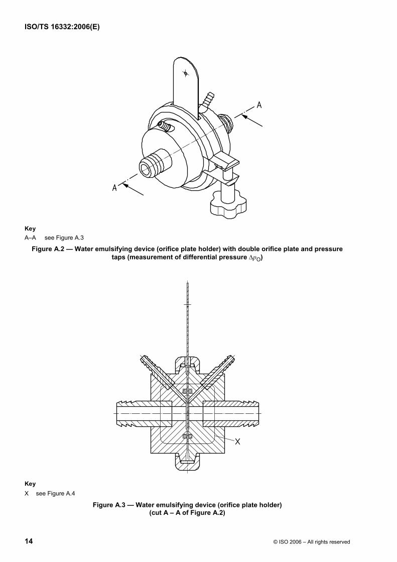
5.3.2.8 Water emulsifying device (9): fixture with an exchangeable orifice plate, as described in Annex A.
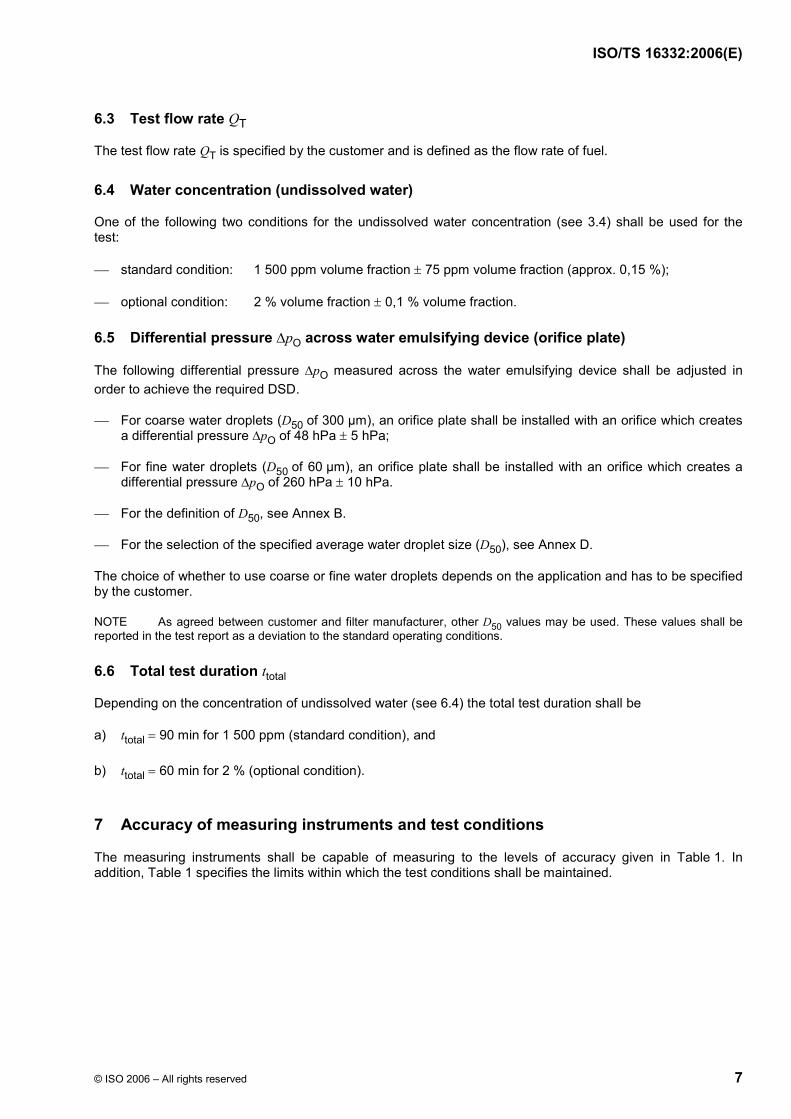
5.3.2.9 Upstream (12) and downstream (17) sampling devices, as shown in Figure 3.
5.3.2.10 Temperature indicator (13) with an accuracy as specified in Table 1.
5.3.2.11 Pressure gauge (10) with an accuracy as specified in Table 1.
5.3.2.12 Differential pressure gauges (11) with an accuracy as specified in Table 1.
5.3.2.13 Water drainage system (15): closed collector (e.g. laboratory measuring cylinder), located directly below the test filter (water separator) (14) and capable to collect the injected amount of water; it is connected to the water outlet of the test filter with pressure-tight fittings.
The internal diameter of the connecting pipe between the test filter and the closed collector shall be of at least 10 mm.
5.3.2.14 Test stand pipes shall be made of stainless steel; painted or coated pipes are not allowed. For the adaptation of the test filter (14) to the test stand piping, flexible lines are allowed.
The piping shall be designed with a minimum number of flanges or fittings and grounded upstream near the test filter (potential difference < 10 V between each point).
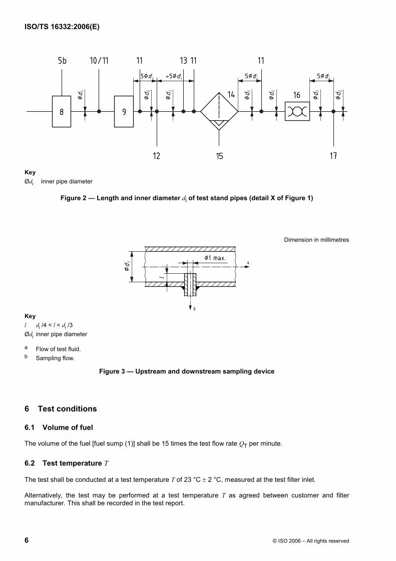
The test stand pipes inner diameter di between injection device (8) and downstream sampling point (17) (see Figure 2) should allow a flow velocity W 0,75 m/s.
The pipes, outside of Figure 2, shall be as short as possible.
5.3.2.15 Inline static mixer (16) to provide a representative sample at the downstream sampling point (17).
NOTE Using a water emulsifying device (see 5.3.2.8 ) has been proven to be suitable as a static mixer.
4) The numbers in brackets refer to the key numbers in Figure 1.
5) Suitable products are available commercially. Details may be obtained from the Secretariat of Technical Committee ISO/TC22 or from the ISO Central Secretariat.
Figure 2 — Length and inner diameter di of test stand pipes (detail X of Figure 1)
Dimension in millimetres
Key l di /4 < l < di /3 Ødi inner pipe diameter
a Flow of test fluid. b Sampling flow.
Figure 3 — Upstream and downstream sampling device
6 Test conditions
6.1 Volume of fuel
The volume of the fuel [fuel sump (1)] shall be 15 times the test flow rate QT per minute.
6.2 Test temperature T
The test shall be conducted at a test temperature T of 23 °C ± 2 °C, measured at the test filter inlet.
Alternatively, the test may be performed at a test temperature T as agreed between customer and filter manufacturer. This shall be recorded in the test report.
6.5 Differential pressure ∆pO across water emulsifying device (orifice plate)
The following differential pressure ∆pO measured across the water emulsifying device shall be adjusted in order to achieve the required DSD.
⎯ For coarse water droplets (D50 of 300 µm), an orifice plate shall be installed with an orifice which creates a differential pressure ∆pO of 48 hPa ± 5 hPa;
⎯ For fine water droplets (D50 of 60 µm), an orifice plate shall be installed with an orifice which creates a differential pressure ∆pO of 260 hPa ± 10 hPa.
⎯ For the definition of D50, see Annex B.
⎯ For the selection of the specified average water droplet size (D50), see Annex D.
The choice of whether to use coarse or fine water droplets depends on the application and has to be specified by the customer.
NOTE As agreed between customer and filter manufacturer, other D50 values may be used. These values shall be reported in the test report as a deviation to the standard operating conditions.
6.6 Total test duration ttotal
Depending on the concentration of undissolved water (see 6.4) the total test duration shall be
a) ttotal = 90 min for 1 500 ppm (standard condition), and
b) ttotal = 60 min for 2 % (optional condition).
7 Accuracy of measuring instruments and test conditions
The measuring instruments shall be capable of measuring to the levels of accuracy given in Table 1. In addition, Table 1 specifies the limits within which the test conditions shall be maintained.
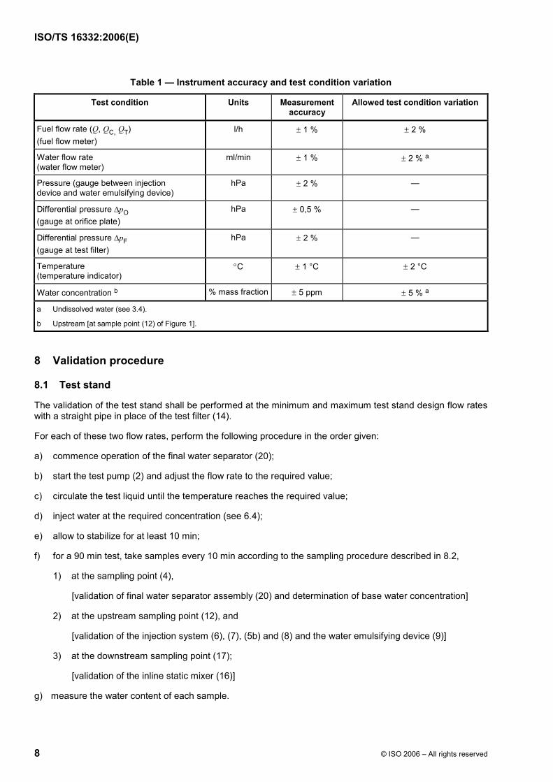
Table 1 — Instrument accuracy and test condition variation
Test condition Units Measurement accuracy
Allowed test condition variation
Fuel flow rate (Q, QC, QT) (fuel flow meter)
l/h ± 1 % ± 2 %
Water flow rate (water flow meter)
ml/min ± 1 % ± 2 % a
Pressure (gauge between injection device and water emulsifying device)
hPa ± 2 % —
Differential pressure ∆pO (gauge at orifice plate)
hPa ± 0,5 % —
Differential pressure ∆pF (gauge at test filter)
hPa ± 2 % —
Temperature (temperature indicator)
°C ± 1 °C ± 2 °C
Water concentration b % mass fraction ± 5 ppm ± 5 % a
a Undissolved water (see 3.4).
b Upstream [at sample point (12) of Figure 1].
8 Validation procedure
8.1 Test stand
The validation of the test stand shall be performed at the minimum and maximum test stand design flow rates with a straight pipe in place of the test filter (14).
For each of these two flow rates, perform the following procedure in the order given:
a) commence operation of the final water separator (20);
b) start the test pump (2) and adjust the flow rate to the required value;
c) circulate the test liquid until the temperature reaches the required value;
d) inject water at the required concentration (see 6.4);
e) allow to stabilize for at least 10 min;
f) for a 90 min test, take samples every 10 min according to the sampling procedure described in 8.2,
1) at the sampling point (4),
[validation of final water separator assembly (20) and determination of base water concentration]
2) at the upstream sampling point (12), and
[validation of the injection system (6), (7), (5b) and (8) and the water emulsifying device (9)]
⎯ at the sampling point (4), the variation between the total water concentration of each sample is less than 30 ppm by volume, and
⎯ at the sampling points (12) and (17), the actual concentration of water of each sample, reduced by the base water concentration, is equal to the injected water concentration, within the limits defined in Table 1.
NOTE Many water in oil analytical devices will determine the water concentration in terms of micrograms. To convert micrograms to parts per million (ppm) by volume, use the following equation:
Titration reading, in ppm volume fraction = titration reading, in ppm mass fraction × fuel/water densities correlation factor
where the fuel/water densities correlation factor is (fuel density, in grams per litre) / (water density, in grams per litre).
8.2 Sampling procedure
8.2.1 Primary sampling procedure
The following procedure shall be executed for the upstream and downstream sampling points:
a) open the sampling valves at sampling points (12) and (17);
b) flush the volume between the sampling points (12) and (17) and discard in an appropriate repository;
c) immediately open the sampling bottles (prepared as described in 5.2.2) and fill approximately 50 ml;
d) close the sampling bottles directly after filling and identify the sample.
If an automatic codistillation unit is used for Karl-Fisher titration, insert the bottles directly in the distillation unit.
If an automatic sampling unit is used, flushing of the sampling pipes and exclusion of humidity inflow into the sample volume shall be assured, until final analysis in titration cells is completed.
8.2.2 Secondary sampling procedure
If a manually served cell is used, homogenize the sample using the same mixer (see 5.2.6) to assure that the water is completely and uniformly dispersed. Use a hypodermic syringe and extract an adequate sample volume as described in 5.2.3.
This secondary sampling procedure shall be validated according to 8.2.3.
8.2.3 Secondary sampling procedure validation
a) Take 51 g ± 0,05 g sample of test fuel;
b) take 1 g ± 0,01 g secondary sample by using a micro-syringe;
c) measure the water content c1;
d) add 0,075 g ± 0,005 g water into remaining 50 g sample and mix by using an ULTRA-TURRAX mixer;
e) take another 1 g ± 0,01 g sample using a micro-syringe;
Perform the pre-test preparation procedure in the following order:
a) install the test filter (14) and water drainage system (15) for testing;
b) choose an orifice plate with a suitable orifice for the required DSD (D50 = 60 µm or D50 = 300 µm) and fuel flow rate QC according to Annex B;
c) install the orifice plate into the holder [water emulsifying device (9)];
d) start circulation at the specified test flow rate QT (see 6.3) and test temperature T (see 6.2). Bleed air from the system including water drainage system (15). Record an initial pressure drop reading at the orifice (9) and at the test filter (14) immediately after the start;
e) record the resulting DSD as described in Annex B;
f) circulate the clean test fluid at the specified test flow rate QT (see 6.3) through the test filter (14) for at least 30 min.
9.2 Efficiency measurement
Perform the following procedure in the order given:
a) commence water injection at the specified test flow rate QT (see 6.3) and start the timing clock at the same time water begins to flow. This point is test time t = 0. Record the differential pressure ∆pO across the orifice (9) and test filter (water separator) (14);
b) after 10 min:
1) take an initial sample at sampling point (4) and measure the water content; this is to determine the base water concentration of the fuel;
2) take an initial upstream sample according to the sampling procedure described in 8.2; analyse the sample immediately to confirm that the specified water concentration is being injected into the fuel stream;
3) take an initial downstream sample according to the sampling procedure described in 8.2; repeat this sampling procedure every 10 min thereafter until termination of the test;
The volume of the samples analysed shall be sufficient to dose at least 50 µg of water into the titration cell.
c) record the differential pressure ∆pO (11) across the orifice (9) and the test filter (14) at each downstream sampling interval;
d) terminate the test if one or more of the following conditions are met:
1) the undissolved water concentration in the downstream sample is above the acceptable level specified by customer or filter manufacturer, or
2) an equilibrium pressure drop across the test filter (14) has been reached and a minimum of 90 min of total test duration ttotal has been attained, or
3) the differential pressure ∆pF across the test filter (14) exceeds an upper limit specified by customer or filter manufacturer;
e) take a final sample at sampling point (4) to verify that the base water concentration did not change [i.e. check of the final water separator (20)];
f) if the base water concentration has not changed, record the volume of water drained from the test filter (14);
g) if the base water concentration has changed by more than 30 ppm, cancel the test; check the final water separator (20) and repeat the steps a) to e).
10 Calculation and reporting of test results
10.1 Calculation of water separation efficiency
Perform the following procedures in the order given:
a) determine and record the concentration of undissolved water of the downstream samples with respect to test time t:
undissolved water = total water − base water
b) plot the concentration of undissolved water in the downstream samples (ppm by volume) versus test time t, in min;
NOTE All following water concentrations ( c , ic , avc ) refer to undissolved water.
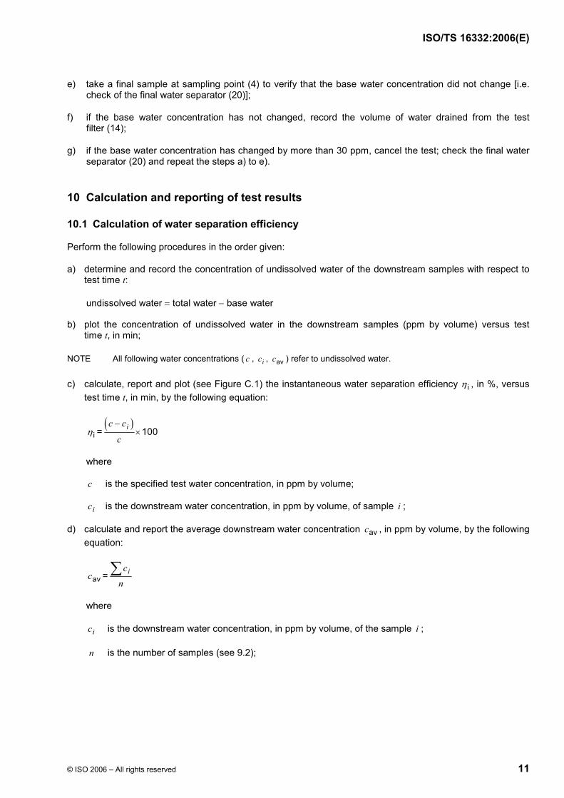
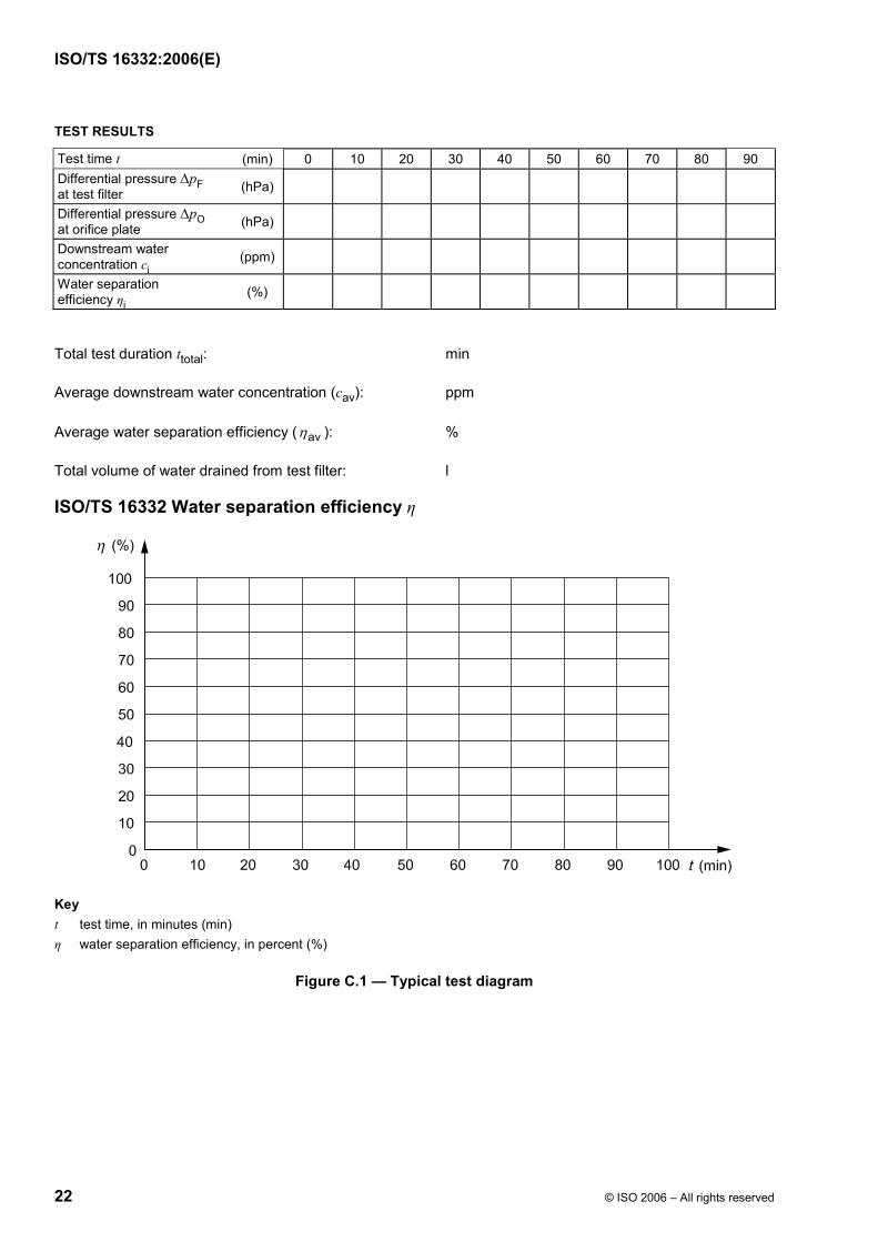
c) calculate, report and plot (see Figure C.1) the instantaneous water separation efficiency iη , in %, versus test time t, in min, by the following equation:
iη =)(
100ic c
c
−×
where
c is the specified test water concentration, in ppm by volume;
ic is the downstream water concentration, in ppm by volume, of sample i ;
d) calculate and report the average downstream water concentration avc , in ppm by volume, by the following equation:
avc = icn∑
where
ic is the downstream water concentration, in ppm by volume, of the sample i ;
Procedure to determine the water droplet size distribution (DSD)
B.1 Water droplet size distribution (DSD) — Definition
The water droplets are generated by dissipating a known energy within the fuel/water mixture by flowing it through a calibrated orifice diameter d (see Figure B.2).
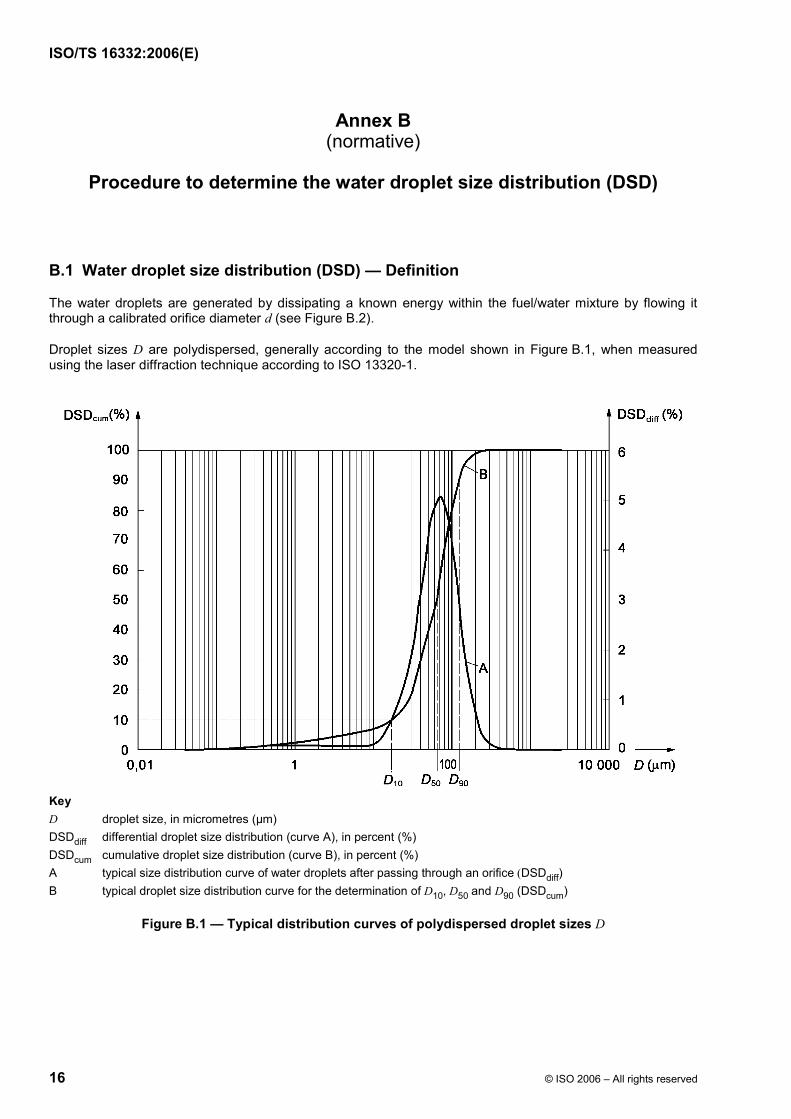
Droplet sizes D are polydispersed, generally according to the model shown in Figure B.1, when measured using the laser diffraction technique according to ISO 13320-1.
Key D droplet size, in micrometres (µm) DSDdiff differential droplet size distribution (curve A), in percent (%) DSDcum cumulative droplet size distribution (curve B), in percent (%) A typical size distribution curve of water droplets after passing through an orifice (DSDdiff) B typical droplet size distribution curve for the determination of D10, D50 and D90 (DSDcum)
Figure B.1 — Typical distribution curves of polydispersed droplet sizes D
Curve A represents the differential distribution of droplet sizes DSDdiff (i.e. percentage of droplets within a size range) and curve B the cumulative one DSDcum (i.e. percentage of droplets smaller than the indicated droplet size D). The cumulative distribution DSDcum can be represented by three droplet sizes:
⎯ D10 is the droplet size D that only 10 % of the droplets underpass.
⎯ D50 is the droplet size D which separates the droplets in two identical populations, 50 % larger and 50 % smaller; i.e., D50 is the average diameter of the droplet size distribution DSD.
⎯ D90 is the droplet size D that only 10 % of the droplet population overpass (90 % underpass).
Since it has been shown by studies performed to develop this Technical Specification that water droplets in fuel have similar Gaussian distributions whatever their average sizes, it has been agreed to characterize this distribution by the D50 figure, only.
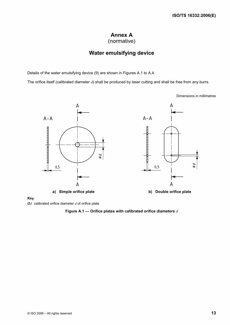
B.2 Calibrated orifices
Because of their simplicity, orifice plates with calibrated orifice diameters d have been used to mix, under known and repeatable conditions, the water with fuel to generate droplets of known size D. The orifice plates are made of 0,5 mm thick stainless steel discs with a central hole of variable inside diameter d (orifice diameter). Typical stainless steel orifice plates with calibrated orifice diameters d (simple and double orifice plates) are shown in Figure A.1.
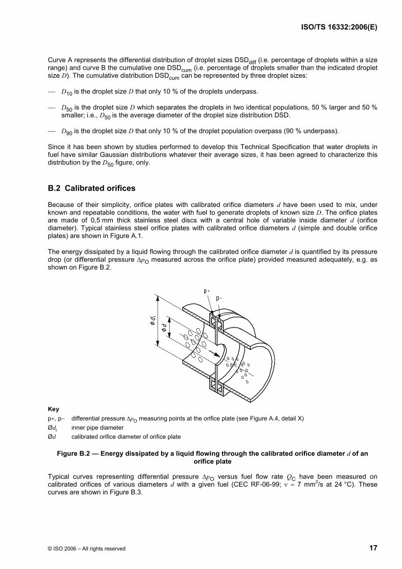
The energy dissipated by a liquid flowing through the calibrated orifice diameter d is quantified by its pressure drop (or differential pressure ∆pO measured across the orifice plate) provided measured adequately, e.g. as shown on Figure B.2.
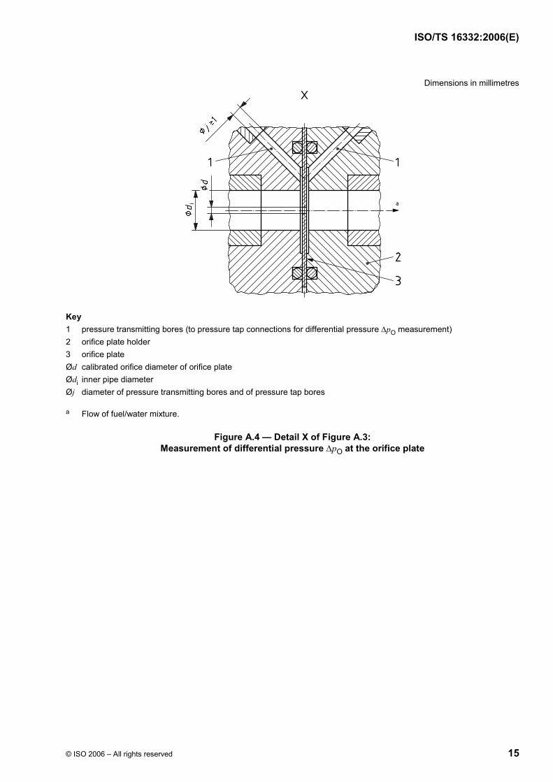
Key p+, p− differential pressure ∆pO measuring points at the orifice plate (see Figure A.4, detail X) Ødi inner pipe diameter Ød calibrated orifice diameter of orifice plate
Figure B.2 — Energy dissipated by a liquid flowing through the calibrated orifice diameter d of an orifice plate
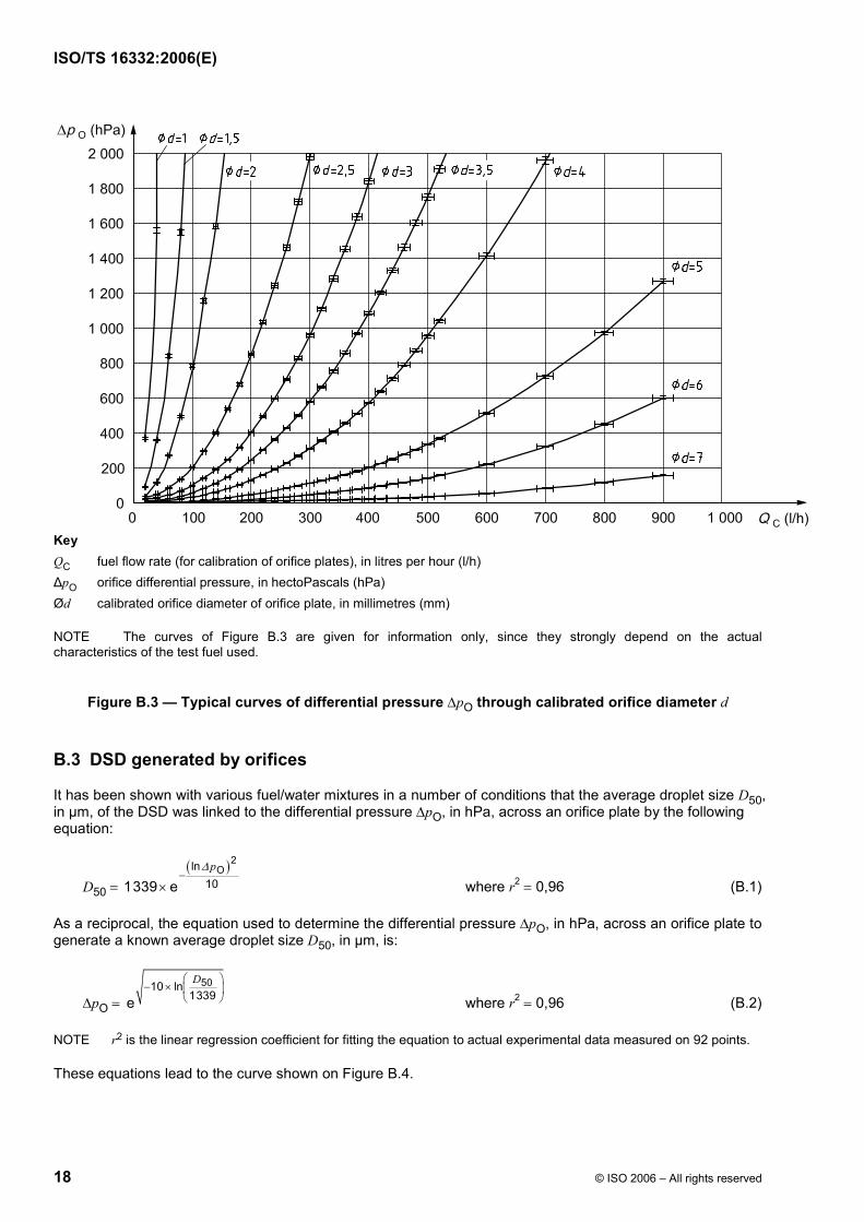
Typical curves representing differential pressure ∆pO versus fuel flow rate QC have been measured on calibrated orifices of various diameters d with a given fuel (CEC RF-06-99; ν = 7 mm2/s at 24 °C). These curves are shown in Figure B.3.
Key QC fuel flow rate (for calibration of orifice plates), in litres per hour (l/h) ∆pO orifice differential pressure, in hectoPascals (hPa) Ød calibrated orifice diameter of orifice plate, in millimetres (mm)
NOTE The curves of Figure B.3 are given for information only, since they strongly depend on the actual characteristics of the test fuel used.
Figure B.3 — Typical curves of differential pressure ∆pO through calibrated orifice diameter d
B.3 DSD generated by orifices
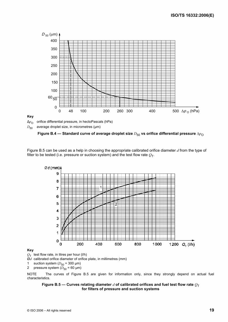
It has been shown with various fuel/water mixtures in a number of conditions that the average droplet size D50, in µm, of the DSD was linked to the differential pressure ∆pO, in hPa, across an orifice plate by the following equation:
D50 = ( )2Oln
101339 ep∆
−× where r2 = 0,96 (B.1)
As a reciprocal, the equation used to determine the differential pressure ∆pO, in hPa, across an orifice plate to generate a known average droplet size D50, in µm, is:
∆pO = 5010 ln
1339e
D⎛ ⎞− × ⎜ ⎟
⎝ ⎠ where r2 = 0,96 (B.2)
NOTE r2 is the linear regression coefficient for fitting the equation to actual experimental data measured on 92 points.
These equations lead to the curve shown on Figure B.4.
Key ∆pO orifice differential pressure, in hectoPascals (hPa) D50 average droplet size, in micrometres (µm)
Figure B.4 — Standard curve of average droplet size D50 vs orifice differential pressure ∆pO
Figure B.5 can be used as a help in choosing the appropriate calibrated orifice diameter d from the type of filter to be tested (i.e. pressure or suction system) and the test flow rate QT.
Key QT test flow rate, in litres per hour (l/h) Ød calibrated orifice diameter of orifice plate, in millimetres (mm) 1 suction system (D50 = 300 µm) 2 pressure system (D50 = 60 µm)
NOTE The curves of Figure B.5 are given for information only, since they strongly depend on actual fuel characteristics.
Figure B.5 — Curves relating diameter d of calibrated orifices and fuel test flow rate QT for filters of pressure and suction systems
B.4 Procedure for determining actual average test DSD
Perform the following procedure in the order given:
a) select the test DSD depending on the type of fuel filter to be tested:
1) for “pressure side” filters, generate fine droplets with a D50 of 60 µm,
2) for “suction side” filters, generate coarse droplets with a D50 of 300 µm;
NOTE Based on the tolerances given in 6.5 on the differential pressure ∆pO at the orifice plates, tolerances on the D50 can be calculated as follows: ± 2 µm on the 60 µm droplets and ± 25 µm on the 300 µm droplets.
b) using Equation (B.2) of B.3 or Figure B.4, determine the corresponding differential pressure ∆pO to be generated through the water emulsifying device;
c) using Figures B.3 or B.4, determine the calibrated orifice diameter d which generates the differential pressure ∆pO determined above, at the test flow rate QT (see 6.3);
d) select and install an available orifice plate with the calibrated orifice diameter d closest to the one calculated in B.4 c);
e) during the test (see 9.2), record the actual differential pressure ∆pO at the installed orifice plate for the test flow rate QT and calculate its average value throughout the test;
f) using Equation (B.1) of B.3 or Figure B.4, determine the actual average test D50 of the DSD and report this in the test report.
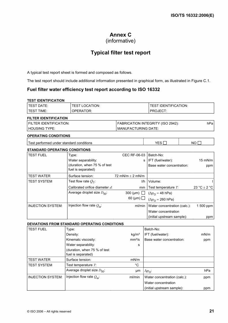
STANDARD OPERATING CONDITIONS TEST FUEL Type: CEC RF-06-03 Batch-No: Water separability:
(duration, when 75 % of test fuel is separated)
s IFT (fuel/water): Base water concentration:
15 mN/mppm
TEST WATER Surface tension: 72 mN/m ± 2 mN/m TEST SYSTEM Test flow rate QT: l/h Volume: l Calibrated orifice diameter d: mm Test temperature T: 23 °C ± 2 °C Average droplet size D50: 300 (µm)
Selection of the specified average water droplet sizes D50
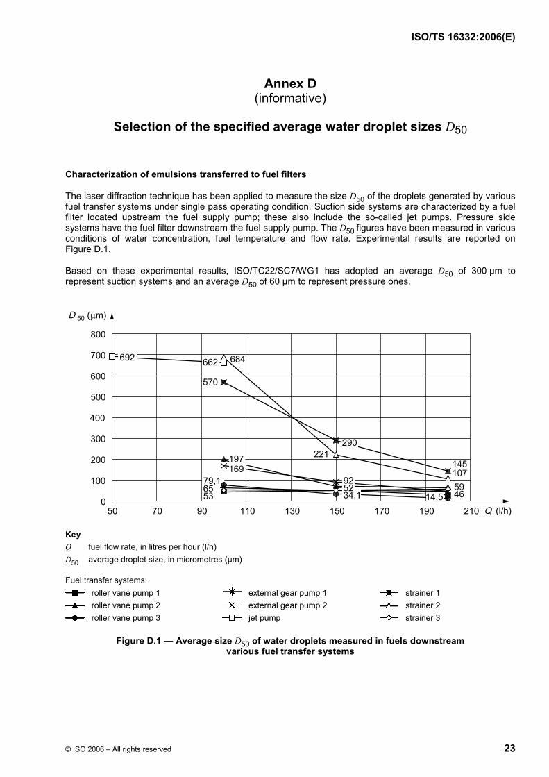
Characterization of emulsions transferred to fuel filters
The laser diffraction technique has been applied to measure the size D50 of the droplets generated by various fuel transfer systems under single pass operating condition. Suction side systems are characterized by a fuel filter located upstream the fuel supply pump; these also include the so-called jet pumps. Pressure side systems have the fuel filter downstream the fuel supply pump. The D50 figures have been measured in various conditions of water concentration, fuel temperature and flow rate. Experimental results are reported on Figure D.1.
Based on these experimental results, ISO/TC22/SC7/WG1 has adopted an average D50 of 300 µm to represent suction systems and an average D50 of 60 µm to represent pressure ones.
Key Q fuel flow rate, in litres per hour (l/h) D50 average droplet size, in micrometres (µm)